Embed Size (px)
Citation preview
7/25/2019 Advanced Shafting Alignment
http://slidepdf.com/reader/full/advanced-shafting-alignment 1/10
203 52(2004)3, 203-212
ADVANCED SHAFTING ALIGNMENT: BEHAVIOUR OF SHAFTING IN OPERATION N. VULI∆UDC 629.5.026.001.42
Nenad VULI∆ Advanced Shafting Alignment:Behaviour of Shafting inOperation
Original scientific paper
Main propulsion shafting plays a significant role in merchant marine ships of nowadays. Theshafting transmits the torque produced by the prime mover to the ship propeller, as well as thepropeller thrust backward to the thrust bearing. Although extensive shafting alignment calculations
and checking procedures are implemented nowadays almost in every newbuilding, many problemsespecially with sterntube bearings still appear in practice. One of the reasons may lie in the factthat all of these calculation and verification procedures refer to the alignment of motionless shaftingrather than to the shafting in operation.
This paper presents an advanced shafting model and a numerical calculation procedure for ashaftline in operating conditions. Shaftline is modelled as a multiple supported girder, taking intoaccount the static properties of the oil-film, formed in the radial journal bearings in operating con-ditions. Important steps in development of the calculation procedure, based on simple girder finiteelements, as well as an advanced static elastic non-linear model of oil-film in bearings are outlinedin the paper. The results of the incremental-iterative calculation of bearing reactions comprise theshafting deflection curve, together with the internal forces and stationary stresses in operation at aselected rpm. Calculated results for a particular ship are shown as an example. Comparison ofthese results with the ones based upon a conventional calculation procedure for a shafting at rest,where the oil-film properties are neglected, confirms the stated hypothesis as significant differ-ences are obtained among them.
Keywords: shafting alignment, bearings, oil-film, calculations, merchant ships.
Unaprijeeno postrojavanje voda vratila: ponaπanje voda vratila u pogonu
Izvorni znanstveni rad
Vod vratila na suvremenim trgovaËkim brodovima igra vrlo znaËajnu ulogu u porivnom sustavu.On prenosi zakretni moment s porivnog stroja na brodski vijak, kao i porivnu silu s brodskog vijkanatrag na odrivni leæaj. UnatoË opseænim proraËunima postrojavanja (centracije) voda vratila ipostupcima provjere, koji se danas provode gotovo bez iznimke na svakoj novogradnji, joπ uvijekse u praksi pojavljuju brojne poteπkoÊe, osobito na statvenim leæajevima. Jedan od razloga za tomoæe biti Ëinjenica da se uobiËajeni postupci proraËuna i provjere postrojavanja odnose iskljuËivona vod vratila u mirovanju, umjesto u pogonu.
U ovom se radu prikazuje sloæeni model voda vratila i postupak numeriËkog proraËuna za vodvratila u pogonskim uvjetima. Vod vratila se modelira kao linijski sustav greda na viπe oslonaca,uzimajuÊi u obzir statiËka svojstva sloja maziva, koji se u pogonu stvara u radijalnim kliznimleæajevima. Prikazani su bitni koraci u razvoju postupka proraËuna, koji se osniva na jednostavnimkonaËnim elementima linijskog sustava, kao i na sloæenom statiËkom nelinearno elastiËnom modelusloja maziva u kliznim leæajevima voda vratila. Rezultati inkrementalno-iterativnog postupkaproraËuna leæajnih reakcija obuhvaÊaju elastiËnu liniju voda vratila, te unutarnje sile i stacionarnanaprezanja za odabranu brzinu vrtnje u pogonu. Prikazan je primjer rezultata proraËuna za stvarnibrod. Usporedba dobivenih rezultata s onima dobivenim na osnovi uobiËajenog postupka proraËunapostrojavanja u mirovanju, kod kojeg se svojstva sloja maziva u leæajevima ne uzimaju u obzir,potvruje postavljenu hipotezu, buduÊi da izmeu njih postoje znaËajne razlike.
KljuËne rijeËi: postrojavanje voda vratila, leæajevi, sloj maziva, proraËuni, trgovaËki brodovi.
Author’s address:
Croatian Register of Shipping MarasoviÊeva 67, 21000 Split, Croatia
1 Introduction
The main propulsion shafting system is an essential part of amodern ship’s propulsion plant. Its purpose is to transmit torque,produced by the prime mover (Diesel engine, steam turbine, gasturbine or an electrical propulsion plant) to the propeller and to
transmit the thrust force, produced by the propeller, back to the
Vod vratila brodskoga porivnog sustava temeljni je dioporivnoga postrojenja na suvremenim brodovima. Njegova je
7/25/2019 Advanced Shafting Alignment
http://slidepdf.com/reader/full/advanced-shafting-alignment 2/10
204 52(2004)3, 203-212
N. VULI∆ ADVANCED SHAFTING ALIGNMENT: BEHAVIOUR OF SHAFTING IN OPERATION
thrust bearing. Shafting is to be designed, produced, installedand tested in such a way that it performs its duty during the wholelife cycle of the ship (i.e. 20 to 30 years). During its exploitationshafting is exposed to various types of loading, which all tend to
reduce its life. This loading may be due to static causes (mis-alignment) and dynamic causes (torsional, axial, flexural andwhirling vibrations about the static elastic line of the shafting).
Owing to the fact that the analysis of the shafting elastic lineis essential for the understanding of the shafting static and vibra-tory behaviour during its life in exploitation, shafting alignmentcalculation has been extensively described in literature, e.g. [1].In addition to these calculations, various shafting alignmentchecking procedures are usually implemented in practice. How-ever, damages and failures of shafting systems have still beenreported from ships throughout the world. One of the possiblecauses of this situation may be the fact that shaft alignment cal-culation and checking usually consider the motionless shafting,i.e. the shafting at rest during the outfitting of the newbuilding in
the shipyard, or during repair works of the existing ship. Thesecalculations and checking procedures always describe how totake into account (at least partially) some of the influences en-countered in the operation – hot vs. cold condition, propellerfully or partially submerged, eccentricity of the propeller thrustforce, influence of the ship’s hull girder and local deformations,etc. [1]. However, they almost never refer to the actual shaftingin operating conditions, when the shafting lies on the oil-film inits bearings.
The basic objective of this paper is to propose a shafting align-ment calculation procedure capable to describe shafting behav-iour in real operating conditions. The basic hypothesis is that thisapproach would give results that may differ much to the ones for a
motionless shafting. The mentioned procedure is not entirely new;it has been basically developed within the Croatian Register of Shipping (CRS) in 1989 [2] and since then implemented in manyCRS classed ships which required shafting alignment calculations,to check what is expected to happen with the shafting in operatingconditions. During the years passed, the procedure has been fur-ther developed and importantly improved. So, the aim of this pa-per is to present the essential improvements in the procedure it-self, as well to illustrate it on an example of a real newbuilding,built under the CRS supervision. As a consequence this paper willnot present the basic (conventional) shafting alignment for ashafting at rest, as described e.g. in [1] and [3].
It is essential to describe the behaviour of the shafting itself as an elastic system (by transfer matrix, or finite elements method)
and the behaviour of the oil (or other lubrication) means in theshafting bearings, the latter introducing non-linearity in the cal-culation procedure.
2 Starting points and basic presumptions
The real shafting system, including its bearings, is modelledby a system of general multispan beams, with several supports,for the calculation purposes. The beam elements are used formodelling of the shafting parts regardless of the computationalmethods implemented (transfer matrix or finite elements method).Bearings are modelled by one of the following support models:absolutely stiff supports, linear elastic supports, or the real model
of radial journal bearings. These models may be used simultane-
namjena prijenos zakretnog momenta, kojega je proizveo po-rivni stroj (dizelski motor, parna turbina, plinska turbina ili elek-trično porivno postrojenje), na brodski vijak, te porivne sile sbrodskog vijka natrag na odrivni ležaj. Vod vratila mora se pro- jektirati, proizvesti, ugraditi i ispitati na način koji će muomogućiti besprijekorno obavljanje zadaće tijekom cijelogradnog vijeka broda (tj. 20 do 30 godina). Tijekom uporabevod vratila izložen je opterećenjima različitih vrsta, koja težesmanjiti njegov vijek trajanja. Ova opterećenja mogu biti iza-zvana statičkim uzrocima (odstupanje elastične linije od crtepostrojavanja) i dinamičkim uzrocima (torzijske, aksijalne, sa-vojne i vitlajuće vibracije oko statičke elastične linije vodavratila).
Budući da je analiza elastične linije voda vratila osnova zarazumijevanje statičkog i vibracijskog ponašanja voda vratilatijekom njegovoga radnog vijeka, proračun postrojavanja vodavratila opsežno je obrađen u literaturi, primjerice [1]. Navedeni
se proračun u praksi potvrđuje različitim postupcima provjerepostrojavanja. Unatoč tomu, s brodova s raznih strana svijeta još uvijek pristižu izvješća o lomovima i oštećenjima voda vra-tila. Jedan je od mogućih uzroka ovakvoga stanja činjenica dase u proračunu i provjerama postrojavanja voda vratila uobi-čajeno razmatra vod vratila u stanju mirovanja. To može bitivod vratila ugrađen na novogradnji u brodogradilištu tijekomopremanja, ili vod vratila na postojećem brodu tijekom remon-tnih radova. Ovaj proračun i postupci provjere redovito opisujukako uzeti u obzir (makar i djelomice) neke od pogonskih utje-caja, primjerice, hladno ili toplo stanje, brodski vijak potpunoili djelomično uronjen u more, ekscentričnost porivne sile, utje-caj deformacija brodskoga trupa kao cjeline i lokalnih defor-macija brodske konstrukcije itd. [1]. Nažalost, svi nabrojeni
utjecaji gotovo se nikad ne odnose na stvarni vod vratila u po-gonu, kad vratilo radi na sloju maziva u svojim kliznim leža- jevima.
Temeljni je cilj ovog rada predložiti postupak proračunapostrojavanja voda vratila koji može opisati ponašanje vodavratila u stvarnim pogonskim uvjetima. Temeljna je hipotezada će takav pristup dati rezultate koji bi se mogli znatno razli-kovati od onih za vod vratila u mirovanju. Navedeni postupaknije u cijelosti nov, budući da je u osnovi razvijen u današnjem Hrvatskom registru brodova ( HRB) tijekom 1989. godine [2].Postupak je od tada primijenjen na mnogim brodovima podnadzorom H RB na kojima je zahtijevan proračun postrojavanjavoda vratila, kako bi se uvidjelo što se može očekivati u pogonu.Stoga je zadatak ovog rada prikazati osnovna poboljšanja uve-
dena u ranije predloženom postupku, kao i prikazati ih na pri-mjeru stvarne novogradnje, građene pod tehničkim nadzoromHRB. Iz rada je zato izostavljen osnovni (uobičajeni) način pro-računa za vod vratila u mirovanju, koji je primjerice opisan u[1] i [3].
Ovdje je bitno opisati ponašanje samoga sastavljenog vodavratila kao linearno elastičnoga sustava (metodom početnihparametara ili metodom konačnih elemenata), te zasebno opisatiponašanje i svojstva sloja maziva (ulja ili suvremenih ekološkihsredstava podmazivanja) u radijalnim kliznim ležajevima, kojaunose nelinearnost u proračunski model.
Vod vratila modelira se kao sustav greda na više oslonaca.Oslonci se mogu modelirati kao apsolutno kruti, linearnoelastični, te stvarni radijalni klizni ležajevi. Različiti modeli
7/25/2019 Advanced Shafting Alignment
http://slidepdf.com/reader/full/advanced-shafting-alignment 3/10
205 52(2004)3, 203-212
ADVANCED SHAFTING ALIGNMENT: BEHAVIOUR OF SHAFTING IN OPERATION N. VULI∆
ously within a single system. The real model of radial journalbearings will be implemented to calculate the elastic line of aship shafting system in operating conditions. This calculation isbased on a static incremental-iterative non-linear elastic calcula-
tion procedure, where its non-linearity is inherited from the modelof the bearings.
3 Methods and solutions
3.1 Modelling of shafting parts
Shafting parts are modelled by means of a system of multispanbeams with a cross-section varying from one beam to another.Each beam has a constant cross-section, which may be solid cir-cular or hollow circular. The most appropriate modelling andcalculation procedures are the methods of initial parameters inits matrix form (so called: transfer-matrix method) and the finiteelements method.
Equivalent results are obtained implementing either of thesetwo approaches. The basic equations of the transfer-matrix ap-proach have been described in [3] and [4] and will not be re-peated here, because the present computer program does notimplement the transfer-matrix approach any more.
Basic equations of the finite element approach start by de-scribing bending and shear in a single plane of an element with aconstant cross-section. The element is exposed to a constantamount of distributed uniform loading along its whole length,from its left to its right end (which may be equal to zero, as aspecial case). The basic equation describing the relation betweenthe element nodal forces and uniform loading with its nodaldisplacements is:
(1)
where:
l – length of the element, EI – element bending stiffness,a – coefficient of shear,q – external uniform distributed transverse loading along
the element,w,j – displacement components (deflection and slope), M , Q – internal forces (bending moment and shear force).
Concentrated forces and moments are added within the cal-culation model separately, as additional nodal values. The equa-tion (1) serves as a basis for development of the three dimen-sional beam element, taking into account the axial and the tor-sional response, as well as the bending and shear in horizontaland the vertical plane, all together, as described in [2]. Bendingand shear in both planes are essential for further calculations.
3.2 Modelling of the bearings
Any combination of the following three models may be usedfor modelling of the bearings in a single shafting system:
a) model of absolutely stiff supports,b) model of linear elastic supports,
c) non-linear model of radial journal bearings.
oslonaca mogu se kombinirati unutar jednoga sustava. Proračunse osniva na statičkom nelinearnom inkrementalno-iterativnommodelu.
U modelu radijalnih kliznih ležajeva u literaturi [2] svoje-
dobno je bio razdvojen osnovni ( L/ D < 1) od proširenog modela( L/ D ≥ 1). Tijekom proteklih godina navedeni su modeli obje-dinjeni u jedinstvenomu modelu, koji predstavlja bitno pobolj-šanje, a u kojemu bi raniji osnovni model bio samo posebanslučaj proširenog.
Jedinstveni je model razmjerno složen, budući da istodobnouzima u obzir utjecaj različitih svojstava sloja maziva uradijalnim kliznim ležajevima. To su ležajna značajka (odnosduljine prema promjeru ležaja) l , Sommerfeldov broj So,relativna ekscentričnost rukavca u ležaju e , kut opterećenjaležaja unutar sloja maziva g , relativni kut nagiba rukavca u ležaju A, te relativni pomak ležajne reakcije X u odnosu na središnjuravninu ležaja (slika 1). Navedena svojstva opisana supolinomnim aproksimacijama, utemeljenim na numeričkimrezultatima iz literature. Rezultati i granice aproksimacijaprikazani su u poglavlju 4.
Svrha je cijeloga postupka proračuna, u kojemu se radijalniklizni ležajevi opisuju pomoću stvarnog nelinearnog jedinstve-nog modela, odrediti prostorni položaj (elastičnu liniju) vodavratila za izabranu brzinu vrtnje, koji zadovoljava uvjete ravno-teže. Ovaj položaj mora zadovoljiti i veze poopćenih pomakarukavca u ležaju (tj. njegove relativne ekscentričnosti i relativ-noga kuta nagiba) s opterećenjem ležaja (izraženim pomoćuSommerfeldova broja). Navedene veze moraju se pri svakojrazini opterećenja zadovoljiti u granicama unaprijed utvrđenepreciznosti (primjerice, 0,01% do 0,1% radijalne zračnostiležaja).
Nasuprot proračuna prikazanog u literaturi [2], koji se osni-vao na čisto iterativnom postupku, u današnjem računalnomprogramu primijenjen je potpuno novi pristup, razvijen u među-vremenu. Teškoće koje su se u čisto iterativnom postupku jav-ljale bile su vezane uz konvergenciju. Ako je postupak divergi-rao, nije se moglo gotovo ništa učiniti. Konvergencija u no-vom, inkrementalno-iterativnom postupku može se postići pode-šavanjem prirasta brzine vrtnje (koja je povezana s opterećenjemležaja).
Iako je znatan broj proračuna na različitim novogradnjamaproveden u međuvremenu prema novom postupku, bio je redproračun prikazati na jednakom primjeru kakav je svojedobnoobrađen u [2], što je i učinjeno. Na taj se način jednostavnozapažaju prednosti novoga pristupa, ako ga se usporedi s ranijim.
Rezultate proračuna za izabrani primjer prikazuju slike 2 do 7.Razdioba poprečnih sila (slika 3) pokazuje znatan porastnjihovih vrijednosti pri nazivnoj brzini vrtnje u usporedbi s oni-ma u mirovanju, osobito na kritičnome mjestu s gledišta proiz-vođača motora, tj. prirubnici spoja koljenastog vratila i među-vratila. Nadalje, momenti savijanja (slika 4) pri nazivnoj brzinivisoko rastu na dijelovima koljenastog vratila. Očito se u prika-zanom slučaju može dogoditi da kriterij prihvatljivosti kojimproizvođač motora ograničava poprečnu silu i moment savijanjane bude ispunjen pri nazivnoj brzini vrtnje, iako je ispunjen umirovanju!Proizvođač motora morao bi o tome povesti računa.
Putanja po kojoj se, s porastom brzine vrtnje, središte ruka-vca postupno giba prema središtu ležaja u središnjoj ravninisimetrije ležaja prikazana je na slici 6. Budući da je poznato da
Q
M
Q
M
EI left
left
right
right
È
Î
Í
Í
Í
Í
˚
=+
◊
- - -
- + -
-
- - +
È
Î
Í
Í
Í
Í
˚
2
1 6
6 3 6 3
3 2 3 3 1 3
6 3 6 3
3 1 3 3 2 3
3
2 2
2 2
l
l l
l l l l
l l
l l l l
( )
( ) ( )
( ) ( )
◊◊
È
Î
Í
Í
Í
Í
˚
+
-
-
-
È
Î
Í
Í
Í
Í
˚
w
w
q left
left
right
right
j
j
l l
l
12
6
6
7/25/2019 Advanced Shafting Alignment
http://slidepdf.com/reader/full/advanced-shafting-alignment 4/10
206 52(2004)3, 203-212
N. VULI∆ ADVANCED SHAFTING ALIGNMENT: BEHAVIOUR OF SHAFTING IN OPERATION
The model of absolutely stiff supports, which neglects thebearings elasticity, is the simplest one and the most widely im-plemented, especially within the conventional shafting alignmentcalculation approach. This model should always be made capa-
ble to take the transversal pre-defined position of supports (i.e.initial displacements) into account.The model of linear elastic supports describes the bearings
as flexible springs, with no preloading. Generally, this model isused in shafting alignment calculations for the shafting at rest,where the shafting part in a bearing (journal) is in direct contactwith the bearing liner. This model, together with the previousone is linear and common. It is described with all the necessarydetails in [2] and [4].
The non-linear model is capable to describe a rather compli-cated real situation. The reference [2] proposed two distinct mod-els for radial journal bearings, with respect to the length and di-ameter ratio ( L/ D) of the bearing. In case of L/ D < 1 the refer-ence [2] prescribed implementation of the so-called basic model.
When the condition L/ D ≥ 1 was met, the extended model was tobe used in accordance with [2].
The major improvement introduced since the time when thereference [2] was published is the unique model of radial journalbearings, presented hereafter. It replaces two separate models(the basic one and the extended one). The essential idea was theconsideration of the former basic model as a special case of theextended one, with some additional presumptions. The presentunique model is valid in the range: 0 ≤ L/ D ≤ 2. The majority of bearings, which implement conventional oil lubrication, or mod-ern environmental harmless lubricants, nowadays meet this con-dition. It should be noted that in modern designs the bearing ra-tios tend not to exceed 2 in order to avoid possible misalignment
problems.3.3 Unique non-linear model of the radial journal
bearings
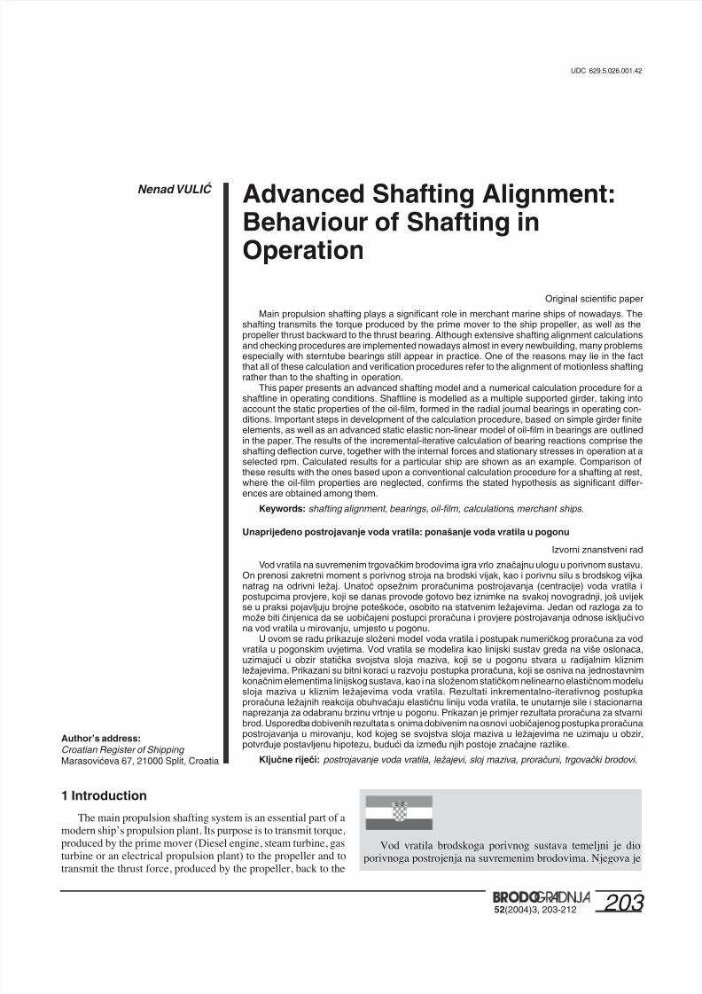
This model is rather complex, because it takes several prop-erties of the oil-film into account. These properties have an im-portant influence to the bearing behaviour. They are: the bearingratio, the Sommerfeld’s number, the journal relative eccentric-ity, the oil-film loading angle, the relative journal misalignmentangle and the relative shift of bearing reaction from the bearingcentral cross-section.
Owing to the fact that in operating conditions the shafting journals lie on a lubricating oil-film, which separates the journalin the bearing from the bearing liner, this model may preciselydescribe behaviour of the bearing and help to determine a realis-tic elastic line of the shafting [5]. However, the further compli-cation is that the model requires a non-linear incremental-itera-tive calculation procedure.
The model is based upon the hydrodynamic theory of lubri-cation and various numerical and experimental results. The theoryfundamentals start from the Reynold’s equation (as described in[2]), and its solutions presented elsewhere in the literature. Thesesolutions describe the static elastic properties of radial journalbearings, i.e. the behaviour of the shafting journal lying on afilm of the lubricating fluid in a journal bearing. Numerical andexperimental results were needed in order to make the modelovercome the theoretical restrictions. All the solutions presented
hereafter are based upon the results from various literature refer-
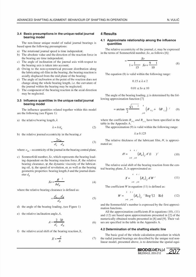
ences approximated by polynomials. Figure 1 denotes the valuesessential to the unique model of radial journal bearings.
Figure 1 Schematic view of the unique model of radial journalbearings
Slika 1 Shematski prikaz jedinstvenog modela radijalnih kliznihleæaja
se to i zbiva u praksi, prikazana putanja može, u nekoj mjeri,poslužiti kao potvrda fizikalne valjanosti cijelog modela.Nadalje, ukoliko se kriterij prihvatljivosti postrojavanja vodavratila osniva na veličini reakcije u stražnjem statvenom ležaju,iz slike 7 uočava se da je ova sila pri nazivnoj brzini vrtnje oko23 posto veća od one u mirovanju. Ova razlika može biti odlu-čujuća! Projektant voda vratila morao bi o tome povesti računa.
Može se zaključiti da se rezultati proračuna statičke elastičnelinije voda vratila u pogonu mogu znatno razlikovati od onihkoji se dobivaju uobičajenim postupkom proračuna za vodvratila u stanju mirovanja. Prikazani rezultati na taj načinpridonose potvrdi uvodno postavljene hipoteze. Primjena tzv.pogonskih vrijednosti (pomaka, sila i sl.) u uobičajenompostupku neće puno pomoći, ukoliko se doista ne uvede razmjer-no složen stvarni model radijalnih kliznih ležajeva. Takav modelzahtijeva nelinearni inkrementalno-iterativni proračun, kojiuključuje određivanje pomaka pojedinih presjeka voda vratila
metodom početnih parametara ili metodom konačnih elemenata,što i nije osobito teško. Teškoću predstavlja prikladan opis zbi-vanja u ležajevima, koji zahtijeva određivanje stvarne “krutosti”ležajeva (veze pomaka s opterećenjima).
Činjenica da vod vratila u pogonu leži na sloju maziva uležajevima, kojeg se debljina znatno mijenja s promjenom le-žajne reakcije, može odlučujuće utjecati na udovoljavanjekriterijima prihvatljivosti postrojavanja voda vratila. Može sedogoditi da vod vratila u mirovanju udovolji kriterijima, a upogonu ne. Ovo bi morali imati na umu stručnjaci u brodogra-dilištima, inspektori brodarskih tvrtki, kao i stručnjaci klasifi-kacijskih zavoda.
Rezultati predloženoga proračunskog modela morajusadržavati: reakcije u ležajevima, ekscentričnosti rukavaca voda
vratila u ležajevima, prostornu elastičnu liniju, momente sa-vijanja, poprečne sile i naprezanja zbog savijanja, sve za različitebrzine vrtnje. Navedeni rezultati mogu služiti kao početnevrijednosti u analizi poprečnih vibracija voda vratila, osobitoako ih se primjerice, pomoću mjernih traka, potvrdi mjerenjemna sličnim brodovima.
F O
L q
g
O R
RO R0
q 0
∆dR
a
R
b/2 b/2
∆dL
D x
7/25/2019 Advanced Shafting Alignment
http://slidepdf.com/reader/full/advanced-shafting-alignment 5/10
207 52(2004)3, 203-212
ADVANCED SHAFTING ALIGNMENT: BEHAVIOUR OF SHAFTING IN OPERATION N. VULI∆
3.4 Basic presumptions in the unique radial journalbearing model
The non-linear unique model of radial journal bearings isbased upon the following presumptions:
a) The rotational journal speed is time independent;b) The absolute value and the direction of the reaction force in
the bearing are time independent;c) The angle of inclination of the journal axis with respect to
the bearing axis is taken into account;d) Owing to the non-symmetrical pressure distribution along
the lubricating oil-film in the bearing, the bearing reaction isaxially displaced from the mid plane of the bearing;
e) The angle of inclination at the point of the reaction does notchange along the whole bearing length, i.e. the curvature of the journal within the bearing may be neglected;
f) The component of the bearing reaction in the axial directionmay be neglected.
3.5 Influence quantities in the unique radial journalbearing model
The influence quantities related together within this modelare the following (see Figure 1):
a) the relative bearing length, l
l = b/d R
(2)
b) the relative journal eccentricity in the bearing, e
(3)
where: e RL
– eccentricity of the journal in the bearing central plane.
c) Sommerfeld number, So, which represents the bearing load-ing dependent on the bearing reaction force, R, the relativebearing clearance, y , the dynamic viscosity of the lubricat-ing oil, h, the speed of revolution, w , as well as the bearinggeometric properties: bearing length, b and the journal diam-eter d
R
(4)
where the relative bearing clearance is defined as:
(5)
d) the angle of the bearing loading, (see Figure 1)
e) the relative inclination angle, A,
(6)
f) the relative axial shift of the bearing reaction, X ,
(7)
4 Results
4.1 Approximate relationship among the influencequantities
The relative eccentricity of the journal, e , may be expressedin the terms of Sommerfeld number, So, as follows [6]:
(8)
The equation (8) is valid within the following range:
0.15 ≤ l ≤ 2
0.01 ≤ So ≤ 10
The angle of the bearing loading, g , is determined by the fol-lowing approximation function [7]
(9)
where the coefficients Bg 0,j
and Bg 1,j
have been specified in thetable in the Appendix A.
The approximation (9) is valid within the following range:
l ≥ 0.125
The relative thickness of the lubricant film, H , is approxi-mated as:
(10)
The relative axial shift of the bearing reaction from the cen-tral bearing plane, X , is approximated as:
(11)
The coefficient W in equation (11) is defined as:
(12)
and the Sommerfeld’s number is expressed by the first approxi-mation functions.
All the approximation coefficients B in equations (10), (11)and (12) are based upon approximations presented in [2] of thenumerically obtained results presented in [8] and [9]. Their val-ues are specified in the table in the Appendix A.
4.2 Determination of the shafting elastic line
The basic goal of the whole calculation procedure in whichthe radial journal bearings are described by the unique real non-
linear model, presented above, is to determine the spatial equi-
=-
2e
d d
RL
L R
So
R
bd R
= y
h
2
y =
-d d
d
L R
R
A b
d d L R
= ◊
-
2
X x
b
= D
l l
=
+ -
Ë
¯+
-
So
So 11
15
9 1
10
g
p
l
g
= -
ËÁ
¯ + ◊( )
=
Âarctan , ,21 2
0 10
4
B B j j
j
j
H B A H ij
i j
j
i
i
= ( ) -
=
-
=
 ( )10
4
0
4
X B A W X ij
i
j
i
i
j = ( )
=
-
=
Â0
4
0
4
W B So W ij
i j
j
i
i
= ( ) ◊ ◊( )=
-
=Â l p
log 20
2
0
2
7/25/2019 Advanced Shafting Alignment
http://slidepdf.com/reader/full/advanced-shafting-alignment 6/10
208 52(2004)3, 203-212
N. VULI∆ ADVANCED SHAFTING ALIGNMENT: BEHAVIOUR OF SHAFTING IN OPERATION
librium position of shafting for a certain speed of revolutions.This position satisfies the relationship of the journal eccentricityand the journal angular inclination with the bearing loading, ex-pressed by the Sommerfeld number. This relationship is to be
satisfied to a predetermined precision, in each loading case.Loading which is to be considered in the present case i.e. thecalculations of operational behaviour of the ship shafting systemdiffers significantly from the loading in the classical static shaftingalignment calculations (for the shafting at rest, neglecting theoil-film in the bearings). In the classical shafting alignment cal-culations loading comprises the propeller weight, weights of theshafting parts, weights of the gears or the turning wheels, takingalso the buoyancy into account, where it is relevant. In the caseof operational behaviour calculations it is very important to in-clude the mean propeller forces and the thrust force eccentricityinto account, as well as the mean operational forces acting ongears or parts of engine reciprocating mechanisms.
Contrary to the calculation procedure presented in [2], which
was based on a pure iterative procedure, a completely new ap-proach has been implemented in the present computer programmeanwhile. The problem with the pure iterative procedure wasthat a non-convergence may happen and there was nothing to doabout it. The convergence in the new procedure, in case of prob-lems, may be obtained by adjusting the increment of rotationalspeed (related to the bearing loading).
The basic idea is to start each calculation step (in which therotational speed is increased) from the previously finished load-ing step in which the elastic line was found to fulfil the equationsof equilibrium, as well as the equations of the real model of ra-dial journal bearings. The calculation procedure for the new loadstep is completely finished, when the change in the eccentricityof all the journals within the bearings, compared to the ones cal-culated in the previous iteration, remains within the predeter-mined limits, e.g. 0.01 to 0.1 per cent of the radial bearing clear-ance.
In each loading (i.e. rotational speed) step the linear finiteelements model of the shafting itself, gives out the bearing reac-tions, R, from which the Sommerfeld numbers, So, as well as the journal inclination anglesa are determined for each bearing. Theradial journal bearing model then returns the displacement val-ues (the bearing eccentricity e , the bearing loading angle g , to-gether with the axial shift of bearing reaction, X ) for each bear-ing. These displacement values then become a new set of bound-ary displacements for the finite elements model, etc., until theconvergence criterion in each bearing has been met.
5 Numerical illustrative example
Though a significant number of calculations have been per-formed based upon the new procedure, since the basic idea wasdeveloped and implemented for the first time, for the sake of good order, the numerical example will be presented for the sameshafting layout as in [2]. Thus, the advantages of the new ap-proach may be easily noticed, comparing the results with theones in [2].
The shaftline of the 28155 GT bulk carrier is considered.The propulsion system is based upon a 6-cylinder two-strokeDiesel engine of maximum continuous rated power of 9180 kWat rated speed of 111 rpm. The system consists of the engine,
directly coupled to the intermediate shaft, then the propeller shaft
and the fixed pitch 4-bladed propeller of 6.450 m diameter. Thepropeller shaft of 580 mm diameter operates in two white metalbearings: the aft and the fore sterntube bearing. The intermediateshaft of 485 mm diameter operates in a single journal white metal
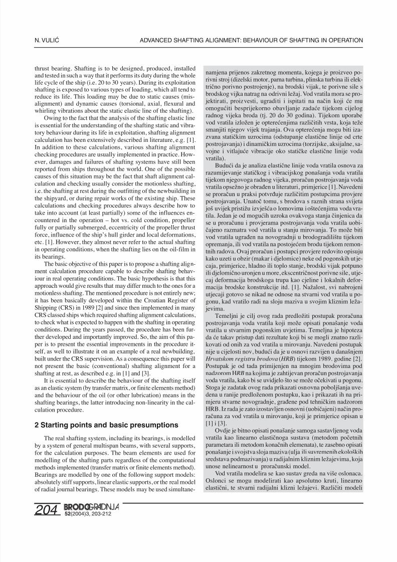
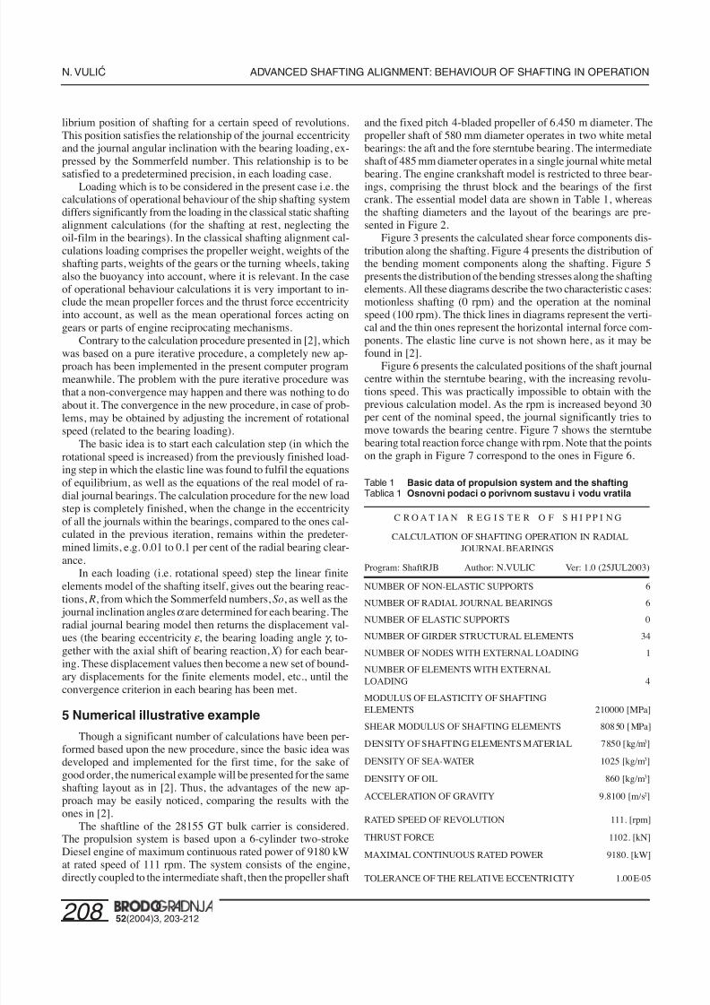
bearing. The engine crankshaft model is restricted to three bear-ings, comprising the thrust block and the bearings of the firstcrank. The essential model data are shown in Table 1, whereasthe shafting diameters and the layout of the bearings are pre-sented in Figure 2.
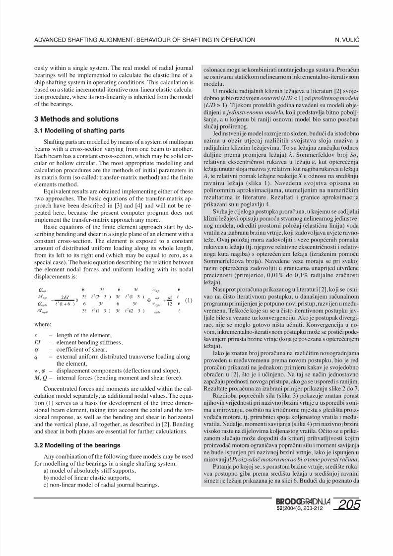
Figure 3 presents the calculated shear force components dis-tribution along the shafting. Figure 4 presents the distribution of the bending moment components along the shafting. Figure 5presents the distribution of the bending stresses along the shaftingelements. All these diagrams describe the two characteristic cases:motionless shafting (0 rpm) and the operation at the nominalspeed (100 rpm). The thick lines in diagrams represent the verti-cal and the thin ones represent the horizontal internal force com-ponents. The elastic line curve is not shown here, as it may be
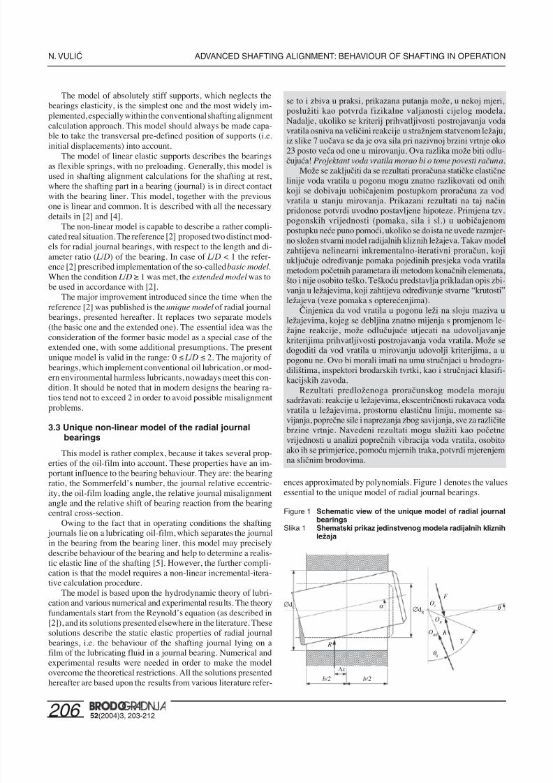
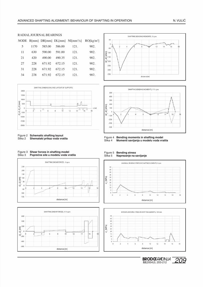
found in [2].Figure 6 presents the calculated positions of the shaft journal
centre within the sterntube bearing, with the increasing revolu-tions speed. This was practically impossible to obtain with theprevious calculation model. As the rpm is increased beyond 30per cent of the nominal speed, the journal significantly tries tomove towards the bearing centre. Figure 7 shows the sterntubebearing total reaction force change with rpm. Note that the pointson the graph in Figure 7 correspond to the ones in Figure 6.
Table 1 Basic data of propulsion system and the shaftingTablica 1 Osnovni podaci o porivnom sustavu i vodu vratila
C R O A T I A N R E G I S T E R O F S H I P P I N G
CALCULATION OF SHAFTING OPERATION IN RADIALJOURNAL BEARINGS
Program: ShaftRJB Author: N.VULIC Ver: 1.0 (25JUL2003)
NUMBER OF NON-ELASTIC SUPPORTS 6
NUMBER OF RADIAL JOURNAL BEARINGS 6
NUMBER OF ELASTIC SUPPORTS 0
NUMBER OF GIRDER STRUCTURAL ELEMENTS 34
NUMBER OF NODES WITH EXTERNAL LOADING 1
NUMBER OF ELEMENTS WITH EXTERNALLOADING 4
MODULUS OF ELASTICITY OF SHAFTINGELEMENTS 210000 [MPa]
SHEAR MODULUS OF SHAFTING ELEMENTS 80850 [MPa]
DENSITY OF SHAFTING ELEMENTS MATERIAL 7850 [kg/m3]
DENSITY OF SEA-WATER 1025 [kg/m3]
DENSITY OF OIL 860 [kg/m3]
ACCELERATION OF GRAVITY 9.8100 [m/s2]
RATED SPEED OF REVOLUTION 111. [rpm]
THRUST FORCE 1102. [kN]
MAXIMAL CONTINUOUS RATED POWER 9180. [kW]
TOLERANCE OF THE RELATIVE ECCENTRICITY 1.00E-05
7/25/2019 Advanced Shafting Alignment
http://slidepdf.com/reader/full/advanced-shafting-alignment 7/10
209 52(2004)3, 203-212
ADVANCED SHAFTING ALIGNMENT: BEHAVIOUR OF SHAFTING IN OPERATION N. VULI∆
RADIAL JOURNAL BEARINGS
NODE B[mm] DR[mm] DL[mm] NI[mm2/s] RO[kg/m3]
5 1170 585.00 586.00 121. 902.
11 630 590.00 591.00 121. 902.
21 420 490.00 490.35 121. 902.
27 228 671.92 672.15 121. 902.
31 228 671.92 672.15 121. 902.
34 228 671.92 672.15 121. 902.
Figure 2 Schematic shafting layoutSlika 2 Shematski prikaz voda vratila
Figure 3 Shear forces in shafting modelSlika 3 PopreËne sile u modelu voda vratila
Figure 4 Bending moments in shafting modelSlika 4 Momenti savijanja u modelu voda vratila
Figure 5 Bending stressSlika 5 Naprezanje na savijanje
Dv/2,DU/2[mm]
distance [m]
Qy,Qz[kN]
Qy,Qz[kN]
distance [m]
My,Mz[kNm]
My,Mz[kNm]
distance [m]
s x
[MPa]
distance [m]
s x
[MPa]
distance [m]
7/25/2019 Advanced Shafting Alignment
http://slidepdf.com/reader/full/advanced-shafting-alignment 8/10
210 52(2004)3, 203-212
N. VULI∆ ADVANCED SHAFTING ALIGNMENT: BEHAVIOUR OF SHAFTING IN OPERATION
6 Discussion of the results
The shearing forces distribution (Figure 3) shows a signifi-cant increase in their value for nominal speed compared to theshafting at rest, which appears to be at the most critical point
with respect to the engine manufacturer’s acceptance criteria,
i.e. the flange connecting the intermediate shaft with the enginecrankshaft. Further on, bending moments (Figure 4) at nominalspeed rise significantly within the engine crankshaft. Obviously,the engine manufacturer’s criteria limiting the shear force andbending moment for the shaft at rest may be not met in operationat nominal speed! The engine manufacturers should be aware of
this situation.The path along which the journal centre moves towards the
bearing centre in the bearing central plane of symmetry, shownin Figure 6, proves that the model of radial journal bearing de-
scribes a physical reality, because this is known to really happen
uy
[mm]
u x [mm]
Journal displacement within sterntube bearing, wrt rpm
30% rpm
100% rpm
rotational speed, n [rpm]
R[kN]
Figure 7 Change of reaction force in sterntube bearing with rpm
Slika 7 Promjena reakcije u straænjem statvenom leæaju s brzi-nom vrtnje
Figure 6 Motion of the sterntube bearing journalSlika 6 Gibanje rukavca u straænjem statvenom leæaju
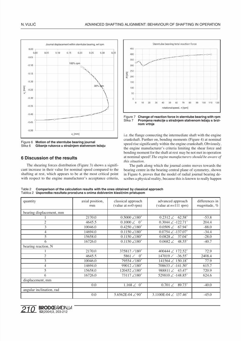
Table 2 Comparison of the calculation results with the ones obtained by classical approachTablica 2 Usporedba rezultata proraËuna s onima dobivenim klasiËnim pristupom
quantity axial position, classical approach advanced approach differences inmm (value at n=0 rpm) (value at n=111 rpm) magnitude, %
bearing displacement, mm 1 2170.0 0.5000 –180˚ 0.2312 – 62.58˚ -53.8 2 4645.5 0.1000 – 0˚ 0.3044 – -122.71˚ 204.4 3 10046.0 0.4250 –180˚ 0.0509 – 67.94˚ -88.0 4 14694.0 0.1150 –180˚ 0.0754 – -137.07˚ -34.4 5 15658.0 0.1150 –180˚ 0.0828 – 37.04˚ -28.0 6 16726.0 0.1150 –180˚ 0.0682 – 48.55˚ -40.7bearing reaction, N 1 2170.0 325812 –180˚ 400444 – 172.52˚ 22.9 2 4645.5 5861 – 0˚ 147019 – -36.55˚ 2408.4 3 10046.0 79554 –180˚ 141564 – 150.18˚ 77.9 4 14694.0 99012 –180˚ 708633 – -141.50˚ 615.7 5 15658.0 120452 –180˚ 988811 – 43.47˚ 720.9 6 16726.0 73117 –180˚ 529810 – -148.85˚ 624.6displacement, mm
0.0 1.168 – 0˚ 0.701 – 89.73˚ -40.0angular inclination, rad
0.0 5.6562E-04 – 90˚ 3.1100E-04 – 137.46˚ -45.0
7/25/2019 Advanced Shafting Alignment
http://slidepdf.com/reader/full/advanced-shafting-alignment 9/10
21152(2004)3, 203-212
ADVANCED SHAFTING ALIGNMENT: BEHAVIOUR OF SHAFTING IN OPERATION N. VULI∆
in practice along such or a similar path. In addition to this, if ashafting alignment acceptance criterion is based upon the valueof the sterntube bearing reaction force, Figure 7 shows that thisforce is by some 23 per cent greater at the nominal speed than
for the shafting at rest. This difference may be decisive! Theshafting designers in shipyards should be aware of this situa-
tion.The results obtained by means of the classical approach (ab-
solutely stiff supports) for the shafting at rest, have been com-pared to the ones obtained by the non-linear model of radial jour-nal bearings. The results of this comparison, presented in Table2, show that there is practically no correlation at all! This meansthat the advanced shafting alignment presented here, gives sig-nificantly different results, with respect to the ones obtained bythe classical approach. A possible speculation whether the shaftingwould avoid problems in exploitation, though it does not satisfythe alignment criteria (e.g. [3]) at the nominal speed, but satis-fies them at rest, as they contain enough safety to cover these
changes, is beyond the scope of this paper.
7 Conclusion
The results of calculations of ship shafting systems elasticline in operating conditions differ significantly from the resultsobtained by the classical shafting alignment calculations that areperformed for the case of motionless shafting. This contributesto prove the hypothesis stated in the introduction. An implemen-tation of the so-called values in operation (forces etc.) cannothelp much unless a rather complicated real model of the bear-ings is introduced. A non-linear incremental iterative calculationalgorithm is to be implemented, based upon modelling of shaftingparts by means of the transfer-matrix method or the finite ele-
ment method. This calculation procedure is to take into accountthe actual bearing behaviour, modelling the bearings by meansof a unique non-linear bearing model, which considers the real“stiffness” (displacements vs. loading relationship) of the lubri-cating oil-film.
The fact that the shafting in operation lies on a film of lubri-cating fluid with the thickness significantly changing with thebearing reactions, may have an important influence on the fulfil-ment of the shafting alignment acceptability criteria. Situationsmay arise in which the shafting may meet the criteria for themotionless state and not meet the criteria at the operating speed.This should be borne in mind by shipyard specialists, shippingcompanies’ superintendents and the classification societies.
The results of such calculations should comprise: bearingreactions, eccentricities of the shaft parts in bearings, axial move-ments of resultant reaction forces, the spatial elastic line of theshafting, bending moments, shear forces and bending stress dis-tributions. These results may be used as a starting point for theanalysis of the shafting behaviour with respect to lateral vibra-tions of the shafting, especially if verified by strain gauge meas-urements on similar existing ships.
References
[1] KOZOUSEK, V.M., DAVIES, P.G.: “Analysis and surveyprocedures of propulsion systems: shaft alignment”, LRTechnical Association, Paper No 5 Session 1999-2000,
Lloyd’s Register of Shipping, London, 2000.
[2] VULIĆ, N.: “Numerical calculation of line systems (Mas-ter’s thesis)”, Faculty of Mechanical Engineering and Na-val Architecture, Zagreb, 1989. (in Croatian)
[3] VULIĆ, N.: “Shafting alignment”, Bulletin of Jugoregistar,
Jugoregistar, Split, 1989. (in Croatian)[4] VULIĆ, N.: “Calculation of main shafting elastic line of shipin operating conditions”, International Design Conference -Design’98, Dubrovnik, 1998, p. 511-516.
[5] HATTORI, K. et. al: “Oil film characteristics of stern tubebearing in consideration of shaft deflection”, Bulletin of theMarine Engineering Society in Japan, 17 (1989) 1, p. 33-44.
[6] ...: DIN 3990 Teil 1 Anhang C, Wellenverlagerung in Gleit-und Wälzlagern infolge Lagerspiel und Lager nachgiebigkeit,1987, p. 60-62.
[7] VUJOŠEVIĆ, B.: “Analytical calculation of bearing stiff-ness and damping coefficients”, Poročila Titovih zavodovLitostroj, - (1987) 7-9, p. 155-164.
[8] LARSEN, O.: “Some Considerations on Marine Shafting
Design”, The Institute of Marine Engineers Transactions (C),1979, p. 12-23.[9] HILL, A., MARTIN, F.A.: “Some Considerations in the De-
sign of Sterntube Bearings and Seals”, The Institute of Ma-rine Engineers Transactions (C), 1979, p. 119-137.
Appendix A: Description of the implementedincremental-iterative numericalprocedure
Step 1: Set initial values and tolerance criteria
Dmax
= (0.1 … 0.5)% C R
– tolerance of the iterative calculations,n
0=0 rpm – shafting at rest,
d 0
=0 – predetermined position of the bearings (determine shafting elastic line at rest),
Step 2: Initial positions of journals and bearing reactions
e RL0 = C R
+ d 0 C R=( D
L- D
R)/2 – radial bearing clearance,
X 0= 0 – axial positions of bearing reactions
Step 3: Initial bearing reactions and inclination angles
R0 , a 0 = f
1(e
RL0 , X 0) – linear finite element calculation, equation (1),
Step 4: Incremental calculation, increase rpm
n = n0+Dn Dn – incremental rpm,
Step 5: Calculate non-dimensional bearing quantities at thepresent rpm
So = f 4( R
0, w , h, bearing dimensions) – equations (4) and (5),
A = f 6 (a
0, bearing dimensions) – equation (6),
e = f 8(So, bearing dimensions) – equation (8),
g = f 9(e , bearing dimensions) – equation (9),
H = f 10
(e , A) – equation (10), X = f
11(So, A, bearing dimensions) – equations (11) and (12),
Step 6: Calculate journal positions, bearing reactions and incli-nation angles at the present rpm
e RL = (1- H )C
R – journal positions within bearings,
R, a = f 1(e RL , X ) – linear finite element calculation, equation (1),
7/25/2019 Advanced Shafting Alignment
http://slidepdf.com/reader/full/advanced-shafting-alignment 10/10
212 52(2004)3, 203-212
N. VULI∆ ADVANCED SHAFTING ALIGNMENT: BEHAVIOUR OF SHAFTING IN OPERATION
Step 7: Calculate achieved maximal differences
D= max |e RL -e RL0
, X - X 0|
Step 8: Differences not yet within tolerance criteria, next itera-
tion necessaryif D> D
max : R
0= R
a0 = a
X 0= X
e RL0
= e RL
continue with the next iteration, step (5)
Step 9: Differences within tolerance criteria, solutions found
if D≤ Dmax : output solutions at n rpme RL0
, X , a, Rn
0= n
continue with the next incremented rpm, step (4),until n
0= n
max
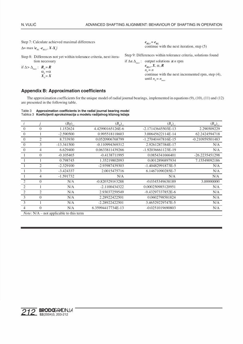
Appendix B: Approximation coefficients
The approximation coefficients for the unique model of radial journal bearings, implemented in equations (9), (10), (11) and (12)are presented in the following table.
Table 3 Approximation coefficients in the radial journal bearing modelTablica 3 Koeficijenti aproksimacija u modelu radijalnog kliznog leæaja
i j ( Bg)i,j
( B H
)i,j
( B X )
i,j ( B
W )
i,j
0 0 1.152624 4.42990165126E-6 -2.17143645503E-13 2.2905092290 1 -2.590500 0.995518118603 3.00645622114E-14 62.24245947180 2 8.733930 0.0520906768799 -1.27040447816E-15 -0.2109595014830 3 -13.341500 -0.110994369312 2.9261287384E-17 N/A0 4 6.629400 0.0633811439266 -1.92036661123E-19 N/A1 0 -0.105465 -0.4138711995 0.0854341666401 -26.22354512981 1 0.798745 1.35219802093 0.0012896897934 7.155490921861 2 -2.329100 -2.93987439303 -1.40482991873E-5 N/A1 3 -3.424337 2.0015475716 6.14671090285E-7 N/A1 4 -1.591732 N/A N/A N/A
2 0 N/A -0.820329163288 -0.0345349638189 3.000000002 1 N/A -2.1100434322 0.000250985120951 N/A2 2 N/A 2.93037259549 -9.43297337852E-6 N/A3 0 N/A 2.28922422501 0.0602798581824 N/A3 1 N/A -2.28922422501 3.46529229747E-5 N/A4 0 N/A 6.35994417734E-13 -0.0251019690803 N/A Note: N/A – not applicable to this term