Embed Size (px)
DESCRIPTION
Advanced Remote Monitoring and Operated Recon Device. Andrew Lichenstein Kevin Jadunandan Thomas Kehr. Special Thanks. Motivation. Dragon Runner surveillance robot Extremely Durable Fast and lightweight platform ≈$32,000 per unit Objectives: Fraction of the Price(< $2500) - PowerPoint PPT Presentation
Citation preview

Advanced Remote Monitoring and Operated Recon Device
Andrew Lichenstein
Kevin Jadunandan
Thomas Kehr

Special Thanks
2

Motivation
3
Dragon Runner surveillance robot Extremely Durable Fast and lightweight platform ≈$32,000 per unit
Objectives: Fraction of the Price(< $2500) Maneuverability on all terrains Wireless Control/Video
iPhone Control
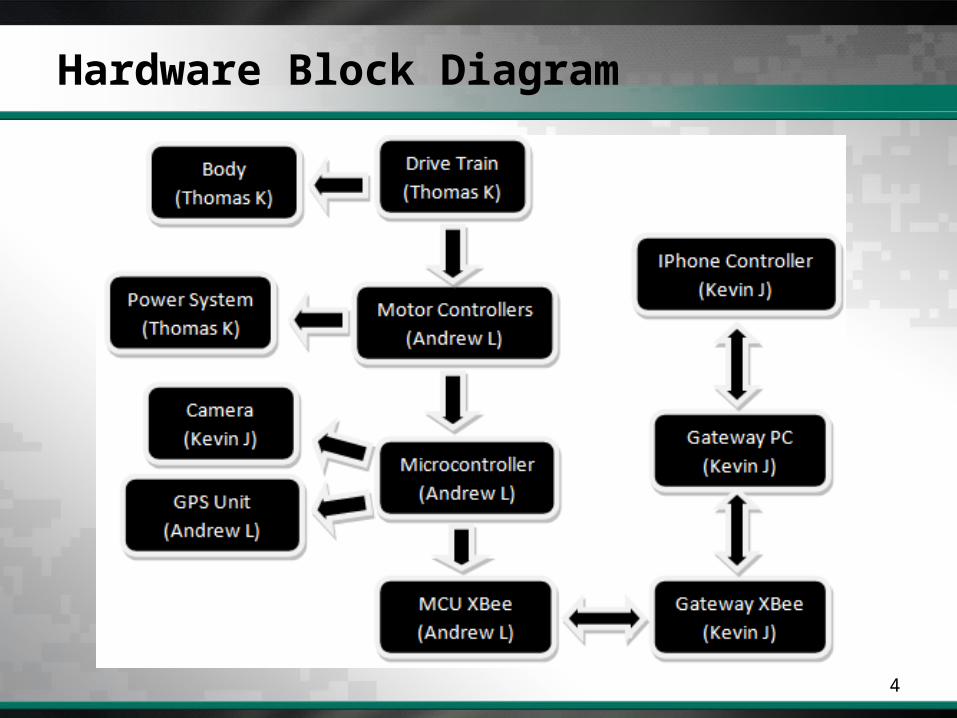
Hardware Block Diagram
4
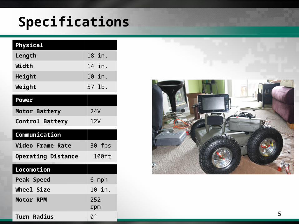
Specifications
5
Physical
Length 18 in.
Width 14 in.
Height 10 in.
Weight 57 lb.
Power
Motor Battery 24V
Control Battery 12V
Communication
Video Frame Rate 30 fps
Operating Distance 100ft
Locomotion
Peak Speed 6 mph
Wheel Size 10 in.
Motor RPM 252 rpm
Turn Radius 0°

Chassis
6
Raw Material Selection
Suspension
Body Design
Component Mounting
Camera

Chassis: Raw Material Selection
7
Aluminum Low-cost Light weight High cost of manipulation
Fiberglass Composite Extremely low cost Easily manipulated High Strength Experienced with fabrication Permeable to Radio frequencies
Fiberglass Carbon Fiber Aluminum
Ultimate Strength (MPa) 3,450 5,650 40-50
Yield Strength (MPa) N/A N/A 15-20
Density (g/cm3) 2.57 1.75 2.7
Average Price ($/ft) 0.91 13.80 7.50
Carbon Fiber High cost High Strength Complex manipulation
Plastic Composite Extremely High Cost High StrengthLight WeightRequires Computer Generated Design

Chassis: Suspension
8
Aluminum Frame – 1/8” Aluminum Sheet Provide mounting for components No metal on metal; rubber washers
Spring Suspension System 32 Springs 8 Motor Clamps

Chassis: Body Design
9
Fiberglass-Composite Construction
Clam-Shell Design
Plug and Mold Fabrication
20”
7”
17”
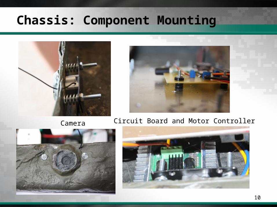
Chassis: Component Mounting
10
Camera Circuit Board and Motor Controller
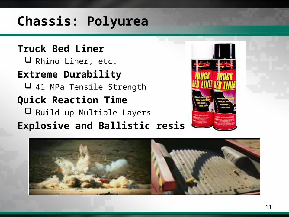
Chassis: Polyurea
11
Truck Bed Liner Rhino Liner, etc.
Extreme Durability 41 MPa Tensile Strength
Quick Reaction Time Build up Multiple Layers
Explosive and Ballistic resistance
Drive Train
12
Geared Motor
Wheels and Locomotion
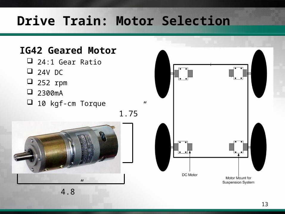
Drive Train: Motor Selection
13
IG42 Geared Motor 24:1 Gear Ratio 24V DC 252 rpm 2300mA 10 kgf-cm Torque
4.8”
1.75”
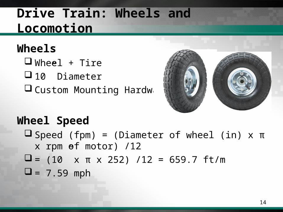
Drive Train: Wheels and Locomotion
14
Wheels Wheel + Tire 10” Diameter Custom Mounting Hardware
Wheel Speed Speed (fpm) = (Diameter of wheel (in) x π x rpm of
motor) /12 = (10” x π x 252) /12 = 659.7 ft/m = 7.59 mph
Power System
15
Batteries
Charging Circuit
Control Battery
Drive Battery

Power System: Batteries
16
NiMH Rechargeable Packs 24V 4500 mAHr
Drive Battery
12V 4000 mAHrControl Battery
5" x 2" x 2"
10" x 2" x 2"

Power System: Charging Circuit
17
DPDT Switch Toggles Between ON-OFF-Charge
Military Style Locking Connector
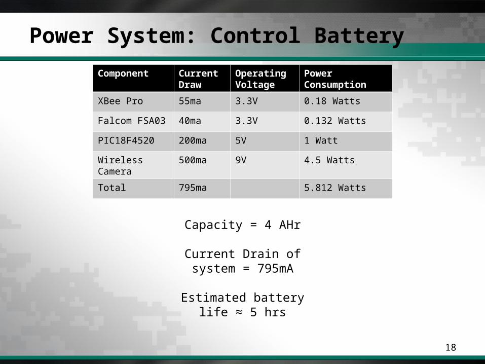
Power System: Control Battery
18
Capacity = 4 AHr
Current Drain of system = 795mA
Estimated battery life ≈ 5 hrs
Component Current Draw
Operating Voltage
Power Consumption
XBee Pro 55ma 3.3V 0.18 Watts
Falcom FSA03 40ma 3.3V 0.132 Watts
PIC18F4520 200ma 5V 1 Watt
Wireless Camera
500ma 9V 4.5 Watts
Total 795ma 5.812 Watts

Power System: Drive Battery
19
Battery Capacity= 4.5 AHr
Current Draw= 2300mA x 4 = 9.2 A
Battery Life = 29.3 minutes
Component Current Draw Operating Voltage
Power Consumption
IG42 Geared Motor 2300mA 24V 55.2Watts

Video System: Camera
20
380-lines resolution
150-foot range (no obstacles)
900 MHz output frequency
Built-in microphone
Internal Hardware
21
MCU
GPS
Communication
Motor Controller
Internal Hardware: MCU
22
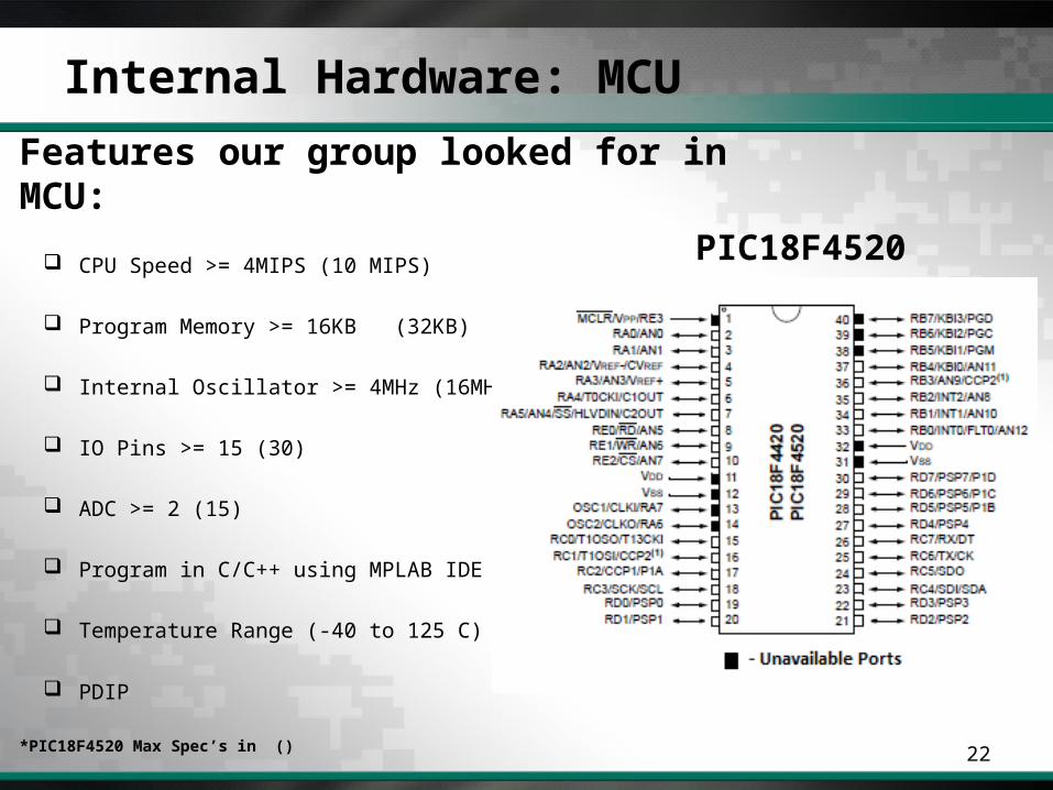
Features our group looked for in MCU:
CPU Speed >= 4MIPS (10 MIPS)
Program Memory >= 16KB (32KB)
Internal Oscillator >= 4MHz (16MHz)
IO Pins >= 15 (30)
ADC >= 2 (15)
Program in C/C++ using MPLAB IDE
Temperature Range (-40 to 125 C)
PDIP
*PIC18F4520 Max Spec’s in ()
PIC18F4520

Internal Hardware: MCU
23
Communication is the most essential part of our robot, we will need to be sending and receiving data from our Gateway to be able to control our robot. We will be using the hardware USART pins on the MCU, which allows us to send serial data reliably.
Our MCU will need to be data parse incoming GPS updates which come in the form of a string of characters. We will be emulating the hardware by emulating the hardware, using software USART.
Motor Control will be done by having two variables set , one for the left motors and one for the right motors. We will be sending a value of 0 to 255, which will tell which motor to move and how which direction it should spin the motor. This also will be using software USART.
Battery life and Temperature value will be done using AD Converters of the MCU, which takes voltage as inputs.

Communication: Options
24
XBee vs. XBee Pro vs. Bluetooth Class 1
XBee XBee Pro Bluetooth Class 1
Indoor Range Up to 100ft
Up to 300ft
Up to 330 ft
Outdoor/LOS Up to 300ft
Up to 1 Mile
Up to 330 ft
Data Rate 250Kbps 250Kbps Up to 3 Mb/s
Unit Price $22.95 $37.95 $59.95
The Bluetooth was a bit to expensive and the regular XBee distance was a bit to small. This is why we chose the XBee Pro which was a good combination of both data rate and distance. We really only need 300 to 400 ft max for our application.
Internal Hardware: GPS
25
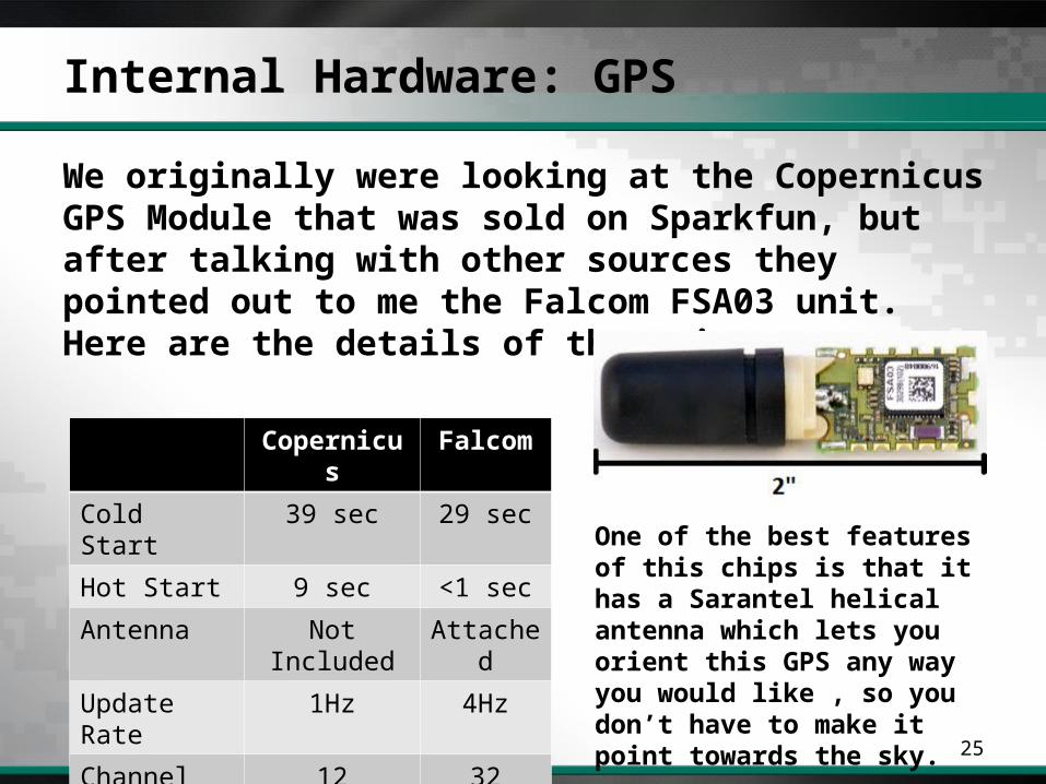
We originally were looking at the Copernicus GPS Module that was sold on Sparkfun, but after talking with other sources they pointed out to me the Falcom FSA03 unit. Here are the details of the unit:
Copernicus Falcom
Cold Start 39 sec 29 sec
Hot Start 9 sec <1 sec
Antenna Not Included Attached
Update Rate 1Hz 4Hz
Channel 12 32
One of the best features of this chips is that it has a Sarantel helical antenna which lets you orient this GPS any way you would like , so you don’t have to make it point towards the sky.
Internal Hardware: Temperature Sensors
26
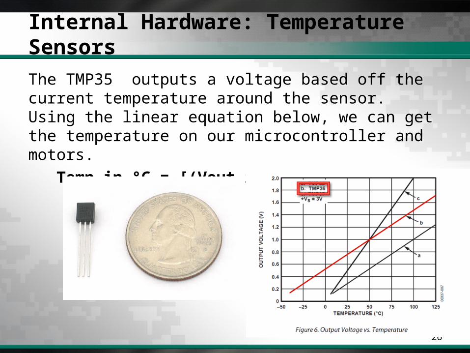
The TMP35 outputs a voltage based off the current temperature around the sensor. Using the linear equation below, we can get the temperature on our microcontroller and motors.
Temp in °C = [(Vout in mV) - 500] / 10

Internal Hardware: Battery Life
27
Using two simple voltage divider circuits to lower the voltage to a max of 5 volts, we check the battery voltage every other second. Knowing our fully charged voltage we can make an assumption on our remaining voltage as the voltage gets lower.

Communication: GPS Purpose
28
The GPS’s main purpose was to be sending latitude and longitude to our microcontroller so that we could use this data with our iPhone application. The GPS sends NMEA(National Marine Electronics Association) data to our MCU; here is an example of what it looks like:
$GPGLL,4916.45,N,12311.12,W,225444,A,*1D
As you can see the data that is sent is not an easy to read format so our MCU will parse the data needed and send to a variable that will be sent out via XBee.
Geographic Lat & Lon
49o16.45
123o11.12
Time(UTC)
Data Active
Checksum
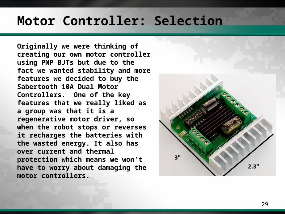
Motor Controller: Selection
29
Originally we were thinking of creating our own motor controller using PNP BJTs but due to the fact we wanted stability and more features we decided to buy the Sabertooth 10A Dual Motor Controllers. One of the key features that we really liked as a group was that it is a regenerative motor driver, so when the robot stops or reverses it recharges the batteries with the wasted energy. It also has over current and thermal protection which means we won’t have to worry about damaging the motor controllers.

Motor Controller: Setup
30
In our setup we will be using two motor controllers in parallel. So we will be using one pin on our MCU a Tx line that uses software USART that connects to the S1 ports on the motor controllers.
The Tx line on the MCU will transmit to both of the motor controllers S1 lines at the same time. We will be sending values of 0 to 255 to the motor controllers .
A value of 1 to 127 controls the left motors and a value of 128 to 255 controls the right motors

MCU Software Diagram
31
RECEIVE THREAD SEND THREAD
DATA STRUCTURES
-Left Motor-Right Motor
-GPSLat-GPSLon
-BatteryLife

Board Design Prototype
32
Created in EagleCAD
Screw Terminals make it easy to connect peripherals and stop wires from falling out
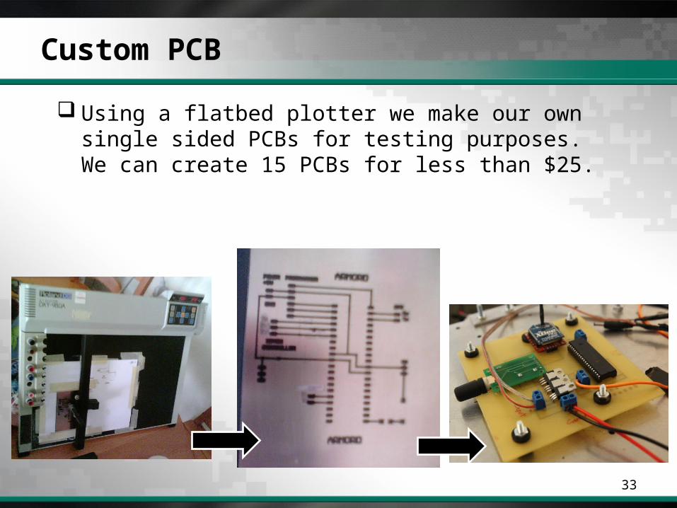
Custom PCB
33
Using a flatbed plotter we make our own single sided PCBs for testing purposes. We can create 15 PCBs for less than $25.
Gateway / iPhone Interface
34
Software applications
iPhone Application
Gateway Application
Last Minute Add-on: iPad App

Software Communication
35

Software
36
iPhone Application Primary controlling device
Touch based interface
Displays map with location of user and ARMORD

Software
37
iPhone Application Written in Objective C
Apple’s object oriented version of C Runs all C code natively
Xcode IDE and Interface Builder Provides drag and drop UI design
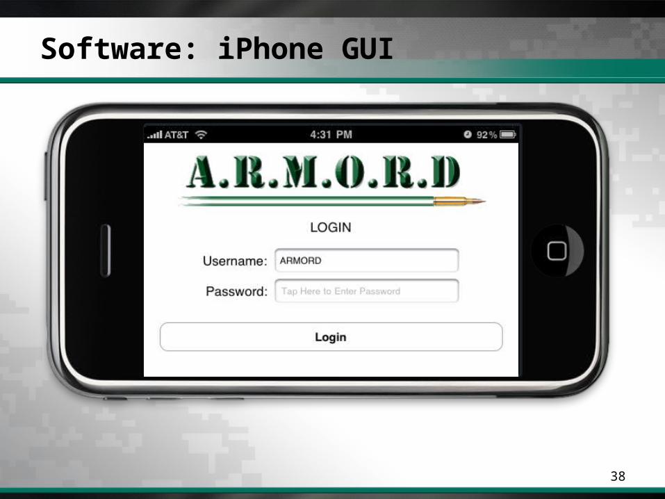
Software: iPhone GUI
38

Software: iPhone GUI
39
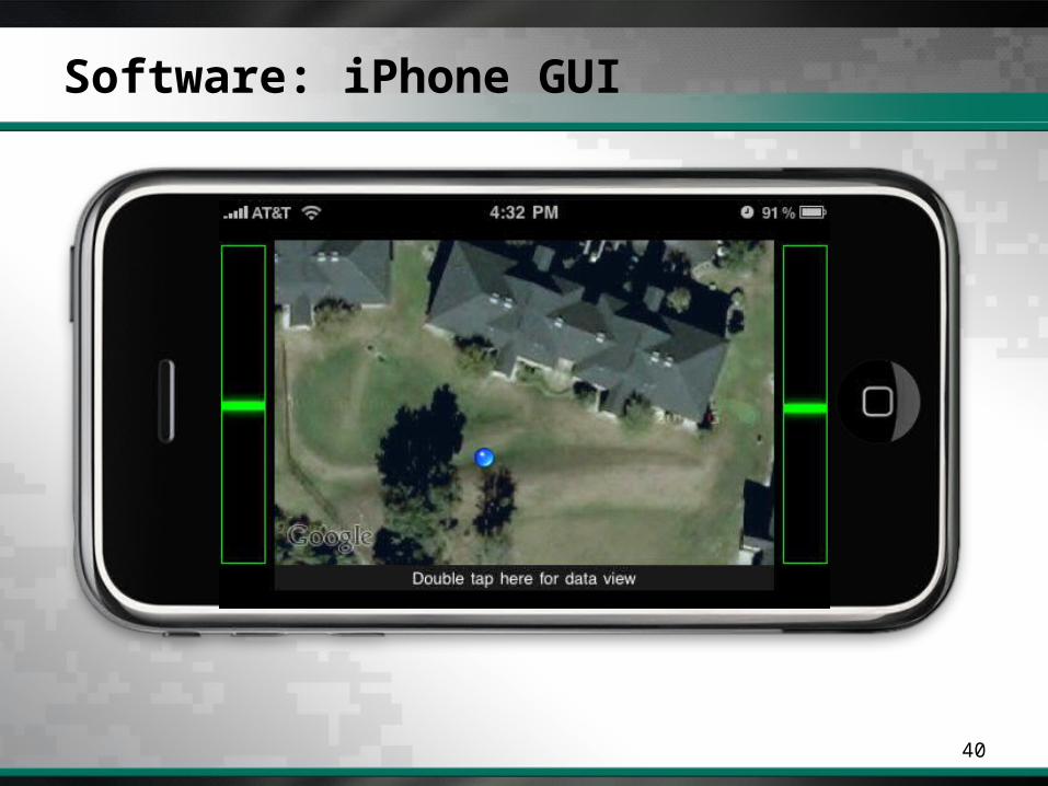
Software: iPhone GUI
40

Software: iPhone GUI
41

Software: iPhone GUI
42

Software: iPhone
43

Software: iPhone
44
Distance Calculation Uses latitude and longitude
Distance in miles =
3963.0 * arccos[sin(lat1) * sin(lat2) +
cos(lat1) * cos(lat2) * cos(lon2 - lon1)]

Software: Gateway Application
45
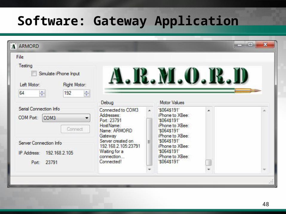
Purpose Wireless bridge between the iPhone and the ARMORD
Necessary because iPhone cannot easily connect to the XBee module
Communication Wi-Fi – iPhone XBee – Robot

Software: Gateway Application
46
Requirements Wi-Fi connection COM port access
Options C# Java
Decision – C# Simple TCP Server and COM Port Access

Software: Gateway Application
47
Software: Gateway Application
48

iPad
49
Control Scheme Turning - Accelerometer based
Forward/Reverse – Slider
“Steering Wheel”

iPad – Screenshot
50

Software
51
Packet Structure From iPhone To ARMORD
From ARMORD To iPhone
$ LEFT_MOTOR $ RIGHT_MOTOR
$ LATITUDE , LONGITUDE , MOTOR_BAT , MCU_BAT
TEMP ;

Video Transmission – Original Design
52
Video is received by video capture card Computer broadcasts live stream over Wi-Fi iPhone plays live stream

Video Transmission – Original Design
53
Problems For live video, iPhone only plays H264 video, with AAC
audio, encapsulated in an MPEG2-TS
Capture card software could not output proper video format
10 second video lag from camera to a computer watching the stream

Video Transmission – New Design
54
Solution – External LCD Display Allows direct video feed from camera to display No processing on a computer to reduce video delay iPhone can now display more information on the
screenMapsGPS locationsDistanceBattery Life

Controller
55
•Components 7” Standalone Monitor Ruggedized Grip and Frame AV Receiver 12V NiMH Battery
Video and Control up to 100 feet
Components attached to controller via aluminum bracket
Power supplied to AV Receiver and Monitor through 12V NiMH battery
Swivel mount to account for inversing camera orientation

Budget
56
Part Name Quantity Price Total Cost
12V 2200mAHr NIMH 1 $23.90 $23.90
12V 4000mAHr NIMH 1 $53.60 $53.60
24V 4500mAHr NIMH 2 $124.80 $249.60
Falcom FSA03 GPS 1 $59.95 $59.95
24V 252 RPM Geared Motor 5 $44.90 $224.50
IPhone Grip 1 $25.50 $25.50
Sabertooth 10A Motor Controller 2 $79.99 $159.98
7 in. LCD 1 $79.99 $79.99
2.4GHz Mini Wireless Camera 2 $42.50 $85.00
900 MHz Mini Wireless Camera 1 $60.00 $60.00
Truck Bed Liner 2 $9.95 $19.90
XBee Pro 3 $37.95 $113.85
XBee USB Explorer 2 $24.95 $49.90
XBee Breakout Board 1 $9.95 $9.95
PIC18F4520 3 $4.50 $13.50
Misc(Body, Copper Clad, Etc.) NA $400.00 $400.00
Developmental Tools NA $350.00 $350.00
Shipping/Handling NA $300.00 $300.00
Total $2429.14

Questions
57
???