Embed Size (px)
Citation preview

Advanced Power ProtectionLecture No.1
Muhammad Riaz

05/07/2023 2
Text Book
• Practical Power System Protection By
L.G Hewitson, Mark Brown and Ramesh Balakrishanan
• Any other reference book or Website
© Muhammad Riaz

05/07/2023 3
Contents
• Need for protective system• Basic requirements• Basic components• Summary
© Muhammad Riaz

05/07/2023 4
Need for protection
• A power system is not only capable to meet the present load but also has the flexibility to meet the future demands
• A power system is designed to generate electric power in sufficient quantity, to meet the present and estimated future demands of the users in a particular area, to transmit it to the areas where it will be used and then distribute it within that area, on a continuous basis.
© Muhammad Riaz

05/07/2023 5
• To ensure the maximum return on the large investment in the equipment, which goes to make up the power system and to keep the users satisfied with reliable service, the whole system must be kept in operation continuously without major breakdowns
© Muhammad Riaz

05/07/2023 6
• The first way is to implement a system adopting components, which should not fail and requires the least or nil maintenance to maintain the continuity of service
• By common sense, implementing such a system is neither economical nor feasible, except for small systems.
© Muhammad Riaz

05/07/2023 7
• The second option is to foresee any possible effects or failures that may cause long-term shutdown of a system, which in turn may take longer time to bring back the system to its normal course
• The main idea is to restrict the disturbances during such failures to a limited area and continue power distribution in the balance areas
© Muhammad Riaz

05/07/2023 8
• Special equipment is normally installed to detect such kind of failures (also called ‘faults’) that can possibly happen in various sections of a system, and to isolate faulty sections so that the interruption is limited to a localized area in the total system covering various area
© Muhammad Riaz

05/07/2023 9
• The special equipment adopted to detect such possible faults is referred to as ‘protective equipment or protective relay’ and the system that uses such equipment is termed as protection system
• A protective relay is the device, which gives instruction to disconnect a faulty part of the system
• This action ensures that the remaining system is still fed with power, and protects the system from further damage due to the fault
© Muhammad Riaz

05/07/2023 10
• Hence, use of protective apparatus is very necessary in the electrical systems, which are expected to generate, transmit and distribute power with least interruptions and restoration time
• It can be well recognized that use of protective equipment are very vital to minimize the effects of faults, which otherwise can kill the whole system.
© Muhammad Riaz

05/07/2023 11
• The special equipment adopted to detect such possible faults is referred to as ‘protective equipment or protective relay’ and the system that uses such equipment is termed as ‘protection system’
• A protective relay is the device, which gives instruction to disconnect a faulty part of the system
• This action ensures that the remaining system is still fed with power, and protects the system from further damage due to the fault
© Muhammad Riaz

05/07/2023 12
• Hence, use of protective apparatus is very necessary in the electrical systems, which are expected to generate, transmit and distribute power with least interruptions and restoration time
• It can be well recognized that use of protective equipment are very vital to minimize the effects of faults, which otherwise can kill the whole system
© Muhammad Riaz

05/07/2023 13
Basic Requirements for Protection
• A protection apparatus has three main functions/duties:– 1. Safeguard the entire system to maintain
continuity of supply– 2. Minimize damage and repair costs where it
senses fault– 3. Ensure safety of personnel.
© Muhammad Riaz

05/07/2023 14
• These requirements are necessary, firstly for early detection and localization of faults, and secondly for prompt removal of faulty equipment from service
• In order to carry out the above duties, protection must have the following qualities:• Selectivity: To detect and isolate the faulty item only.• Stability: To leave all healthy circuits intact to ensure continuity or supply.• Sensitivity: To detect even the smallest fault, current or system abnormalities and operate correctly at its setting before the fault causes irreparable damage.• Speed: To operate speedily when it is called upon to do so, thereby minimizing damage to the surroundings and ensuring safety to personnel.
© Muhammad Riaz

05/07/2023 15
Basic components of protection• Protection of any distribution system is a function of many
elements and this manual gives a brief outline of various components that go in protecting a system
• Following are the main components of protection;• Fuse is the self-destructing one, which carries the currents in
a power circuit continuously and sacrifices itself by blowing under abnormal conditions
• These are normally independent or stand-alone protective components in an electrical system unlike a circuit breaker, which necessarily requires the support of external components
© Muhammad Riaz

05/07/2023 16
• Accurate protection cannot be achieved without properly measuring the normal and abnormal conditions of a system
• In electrical systems, voltage and current measurements give feedback on whether a system is healthy or not
• Voltage transformers and current transformers measure these basic parameters and are capable of providing accurate measurement during fault conditions without failure
© Muhammad Riaz

05/07/2023 17
• The measured values are converted into analog and/or digital signals and are made to operate the relays, which in turn isolate the circuits by opening the faulty circuits. In most of the cases, the relays provide two functions viz., alarm and trip, once the abnormality is noticed
• The relays in old days had very limited functions and were quite bulky
• However, with advancement in digital technology and use of microprocessors, relays monitor various parameters, which give complete history of a system during both pre-fault and post-fault conditions
© Muhammad Riaz

05/07/2023 18
• The opening of faulty circuits requires some time, which may be in milliseconds, which for a common day life could be insignificant
• However, the circuit breakers, which are used to isolate the faulty circuits, are capable of carrying these fault currents until the fault currents are totally cleared
• The circuit breakers are the main isolating devices in a distribution system, which can be said to directly protect the system
© Muhammad Riaz

05/07/2023 19
• The operation of relays and breakers require power sources, which shall not be affected by faults in the main distribution
• Hence, the other component, which is vital in protective system, is batteries that are used to ensure uninterrupted power to relays and breaker coils
© Muhammad Riaz

05/07/2023 20
Faults, types and effects
• When a consumer requests electrical power from a supply authority, ideally all that is required is a cable and a transformer, shown physically as in Figure 2.1
• While Radial Distribution system is shown in figure 2.2
© Muhammad Riaz

05/07/2023 21© Muhammad Riaz

05/07/2023 22© Muhammad Riaz

05/07/2023 23
Advantages and disadvantages of Radial system
• If a fault occurs at T2 then only the protection on one leg connecting T2 is called into operation to isolate this leg
• The other consumers are not affected• If the conductor to T2 fails, then supply to this
particular consumer is lost completely and cannot be restored until the conductor is replaced/repaired.
© Muhammad Riaz

05/07/2023 24
• This disadvantage can be overcome by introducing additional/parallel feeders as shown in figure, connecting each of the consumers radially as shown in next slide
• However, this requires more cabling and is not always economical
• The fault current also tends to increase due to use of two cables
© Muhammad Riaz

05/07/2023 25
Radial Distribution system with parallel feeders
© Muhammad Riaz

05/07/2023 26
• The Ring main system, which is the most favored, then came into being
• Here each consumer has two feeders but connected in different paths to ensure continuity of power, in case of conductor failure in any section.
© Muhammad Riaz

05/07/2023 27
Ring Main Distribution system
© Muhammad Riaz

05/07/2023 28
• Essentially, meets the requirements of two alternative feeds to give 100% continuity of supply, whilst saving in cabling/copper compared to parallel feeders
• For faults at T1 fault current is fed into fault via two parallel paths effectively reducing the impedance from the source to the fault location, and hence the fault current is much higher compared to a radial path
• The fault currents in particular could vary depending on the exact location of the fault
© Muhammad Riaz

05/07/2023 29
• Protection must therefore be fast and discriminate correctly, so that other consumers are not interrupted
• The above case basically covers feeder failure, since cable tend to be the most vulnerable component in the network
• Not only are they likely to be hit by a pick or alternatively dug-up, or crushed by heavy machinery, but their joints are notoriously weak, being susceptible to moisture, ingress, etc., amongst other things
© Muhammad Riaz

05/07/2023 30
• Transformer faults are not so frequent, however they do occur as windings are often strained when carrying through-fault current
• Also, their insulation lifespan is very often reduced due to temporary or extended overloading leading to eventual failure
• Hence interruption or restriction in the power being distributed cannot be avoided in case of transformer failures
© Muhammad Riaz

05/07/2023 31
• Busbars on the other hand, are considered to be the most vital component on a distribution system. They form an electrical ‘node’ where many circuits come together, feeding in and sending out power
• On E.H.V. systems where mainly outdoor switchgear is used, it is relatively easy and economical to install duplicate busbar system to provide alternate power paths
• But on medium-voltage (11 kV and 6.6 kV) and low-voltage (3.3 kV, 1000 V and 500 V) systems, where indoor metal clad switchgear is extensively used, it is not practical or economical to provide standby or parallel switchboards
• Further, duplicate busbar switchgear is not immune to the damage of a busbar fault
© Muhammad Riaz

05/07/2023 32
• The loss of a busbar in a network can in fact be a catastrophic situation, and it is recommended that this component be given careful consideration from a protection viewpoint when designing network, particularly for continuous process plants such as mineral processing
© Muhammad Riaz

05/07/2023 33
Fault types and their effects
• It is not practical to design and build electrical equipment or networks to eliminate the possibility of failure in service
• It is therefore an everyday fact that different types of faults occur on electrical systems, however infrequently, and at random locations
• Faults can be broadly classified into two main areas, which have been designated ‘active’ and ‘passive’
© Muhammad Riaz

05/07/2023 34
Active faults
• The ‘active’ fault is when actual current flows from one phase conductor to another (phase-to-phase), or alternatively from one phase conductor to earth (phase-to-earth)
• This type of fault can also be further classified into two areas, namely the ‘solid’ fault and the ‘incipient’(Beginning) fault
© Muhammad Riaz

05/07/2023 35
• The solid fault occurs as a result of an immediate complete breakdown of insulation as would happen if, say, a pick struck an underground cable, bridging conductors, etc. or the cable was dug up by a bulldozer
• In mining, a rockfall could crush a cable, as would a shuttle car
• In these circumstances the fault current would be very high resulting in an electrical explosion
© Muhammad Riaz

05/07/2023 36
• This type of fault must be cleared as quickly as possible, otherwise there will be:– Increased damage at fault location– Fault energy = I2 × Rf × t , where t is time in seconds.– Danger to operating personnel (flashes due to high fault
energy sustaining for a long time).– Danger of igniting combustible gas in hazardous areas, such
as methane in coal mines which could cause horrendous disaster.
– Increased probability of earth faults spreading to healthy phases
© Muhammad Riaz

05/07/2023 37
• Higher mechanical and thermal stressing of all items of plant carrying the fault current, particularly transformers whose windings suffer progressive and cumulative deterioration because of the enormous electromechanical forces caused by multi-phase faults proportional to the square of the fault current
• Sustained voltage dips resulting in motor (and generator) instability leading to extensive shutdown at the plant concerned and possibly other nearby plants connected to the system
© Muhammad Riaz
05/07/2023 38
• The ‘incipient’ fault, on the other hand, is a fault that starts as a small thing and gets developed into catastrophic failure. Like for example some partial discharge (excessive discharge activity often referred to as Corona) in a void in the insulation over an extended period can burn away adjacent insulation, eventually spreading further and developing into a ‘solid’ fault
© Muhammad Riaz
05/07/2023 39
• Other causes can typically be a high-resistance joint or contact, alternatively pollution of insulators causing tracking across their surface
• Once tracking occurs, any surrounding air will ionize which then behaves like a solid conductor consequently creating a ‘solid’ fault
© Muhammad Riaz

05/07/2023 40
Passive Faults• Passive faults are not real faults in the true sense of the word,
but are rather conditions that are stressing the system beyond its design capacity, so that ultimately active faults will occur
• Typical examples are:• Overloading leading to over heating of insulation
(deteriorating quality, reduced life and ultimate failure).• Overvoltage: Stressing the insulation beyond its withstand
capacities.• Under frequency: Causing plant to behave incorrectly.• Power swings: Generators going out-of-step or out-of-
synchronism with each other
© Muhammad Riaz

05/07/2023 41
• Largely, the power distribution is globally a three-phase distribution especially from power sources
• The types of faults that can occur on a three-phase AC system are shown in Figure;
© Muhammad Riaz

05/07/2023 42
Different types of Faults
© Muhammad Riaz

05/07/2023 43
• Types of faults on a three-phase system: (A) Phase-to-earth fault; (B) Phase-to-phase fault; (C) Phase-to phase- to-earth fault; (D) Three-phase fault; (E) Three-phase-to-earth fault; (F) Phase-to-pilot fault*; (G) Pilot-to-earth fault
© Muhammad Riaz

05/07/2023 44
• It will be noted that for a phase-to-phase fault, the currents will be high, because the fault current is only limited by the inherent (natural) series impedance of the power system up to the point of fault (Ohm’s law)
• By design, this inherent series impedance in a power system is purposely chosen to be as low as possible in order to get maximum power transfer to the consumer so that unnecessary losses in the network are limited thereby increasing the distribution efficiency
• Hence, the fault current cannot be decreased without a compromise on the distribution efficiency, and further reduction cannot be substantial
© Muhammad Riaz

05/07/2023 45
• On the other hand, the magnitude of earth fault currents will be determined by the manner in which the system neutral is earthed
• It is worth noting at this juncture that it is possible to control the level of earth fault current that can flow by the judicious choice of earthing arrangements for the neutral
© Muhammad Riaz

05/07/2023 46
• Solid neutral earthing means high earth fault currents, being limited by the inherent earth fault (zero sequence) impedance of the system, whereas additional impedance introduced between neutral and earth can result in comparatively lower earth fault currents
• In other words, by the use of resistance or impedance in the neutral of the system, earth fault currents can be engineered to be at whatever level desired and are therefore controllable
• This cannot be achieved for phase faults
© Muhammad Riaz

05/07/2023 47
Transient and permanent faults• Transient faults are faults, which do not damage the insulation
permanently and allow the circuit to be safely re-energized after a short period.
• A typical example would be an insulator flashover following a lightning strike, which would be successfully cleared on opening of the circuit breaker, which could then be automatically closed. Transient faults occur mainly on outdoor equipment where air is the main insulating medium
• Permanent faults, as the name implies, are the result of permanent damage to the insulation
• In this case, the equipment has to be repaired and recharging must not be entertained before repair/restoration
© Muhammad Riaz

05/07/2023 48
Symmetrical and asymmetrical faults
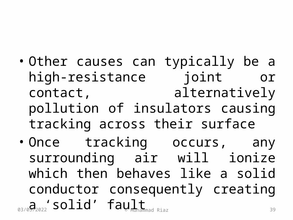
• A symmetrical fault is a balanced fault with the sinusoidal waves being equal about their axes, and represents a steady-state condition
• An asymmetrical fault displays a DC offset, transient in nature and decaying to the steady state of the symmetrical fault after a period of time, as shown in Figure
© Muhammad Riaz
05/07/2023 49© Muhammad Riaz

05/07/2023 50
Asymmetry Factor Chart
© Muhammad Riaz

05/07/2023 51
• The amount of offset depends on the X/R (power factor) of the power system and the first peak can be as high as 2.55 times the steady-state level
© Muhammad Riaz

05/07/2023 52
Example of power station
© Muhammad Riaz

05/07/2023 53
Effect of fault on Transmission lines
© Muhammad Riaz

05/07/2023 54
Protection equipment• The definitions that follow are generally used in relation
to power system protection:– a. Protection System: a complete arrangement of protection
equipment and other devices required to achieve a specified function based on a protection principal (IEC 60255-20)
– b. Protection Equipment: a collection of protection devices (relays, fuses, etc.). Excluded are devices such as CT’s, CB’s, Contactors, etc.
– c. Protection Scheme: a collection of protection equipment providing a defined function and including all equipment required to make the scheme work (i.e. relays, CT’s, CB’s, batteries, etc.)
© Muhammad Riaz

05/07/2023 55
General Relaying Requirement• In order to fulfil the requirements of protection with the
optimum speed for the many different configurations, operating conditions and construction features of power systems, it has been necessary to develop many types of relay that respond to various functions of the power system quantities
• For example, observation simply of the magnitude of the fault current suffices in some cases but measurement of power or impedance may be necessary in others
• Relays frequently measure complex functions of the system quantities, which are only readily expressible by mathematical or graphical means
© Muhammad Riaz

05/07/2023 56
• Relays may be classified according to the technology used:
• a. electromechanical• b. static• c. digital• d. numerical
© Muhammad Riaz

05/07/2023 57
Next Lecture
• Calculations and Zones of Protection
© Muhammad Riaz