Embed Size (px)
Citation preview

N89-24716 Advanced Photovoltaic Solar Array Development*
Richard M. Kurland TR W Space 0 Technology Group Redondo Beach, California 90278
Paul Stella Jet Propulsion Laboratory
California Institute of Technology Pasadena, California 91109
Summary
The Jet Propulsion Laboratory (JPL), under sponsorship from the NASA Office of Aeronau- tics and Space Technology (OAST), has pursued the development of high performance solar array component technology for more than a decade in anticipation of the eventual need by the year 2000 for an array with a specific power of 300 W/kg at beginning-of-life (BOL) at a power level of 25 kW (BOL). In 1985, the Advanced Photovoltaic Solar Array (APSA) program was initiated to combine the separate advanced array component efforts and demonstrate a producible array system by the end of this decade. JPL selected >130 W/kg (BOL) at a 10 kW (BOL) array power level as an in- termediate near-term milestone specific power goal, which would provide a cost- and weight-effective alternative to radioisotope thermoelectric generators for interplanetary missions and also meet the needs of a wide range of near-earth military, scientific, and commercial missions. Phase I of the APSA program was completed in 1986 with preliminary design of an ultralightweight, flatpack fold- out flexible blanket wing that met all the critical electrical and mechanical performance goals using existing and near-term technology. The design represents a factor-of-two improvement in the 66 W/kg (BOL) SAFE I flexible-blanket wing developed by NASA-OAST and flight-demonstrated in 1984 on STS-41D. It also represents a three-fold improvement in the specific power performance of current rigid-panel planar arrays. Phase I1 of the APSA program, started in mid-1987, is currently in progress to fabricate prototype wing hardware that will lead to wing integration and testing in 1989. This paper reviews the design configuration and key details, provides a status of prototype hardware fabricated to date, discusses results from key component-level tests, and shows revised estimates of array-level performance as a function of solar cell device technology for geosynchronous missions.
Program Definition
Figure 1 presents the overall development schedule for the current APSA program, whose goal is to demonstrate a prototype wing with a projected specific power performance of >I30 W/kg (BOL). Phase I, completed in 1986, led to the selection of a preferred design concept and a contractor to
*This paper presents the results of one phase of the Advanced Photovoltaic Solar Array program carried out by TRW Space & Technology Group for the Jet Propulsion Laboratory (JPL), Califor- nia Institute of Technology, under JPL Contract 957990, sponsored by NASA/OAST (NAS7-918). Primary units for measurements and calculations are in the English System.
122
https://ntrs.nasa.gov/search.jsp?R=19890015345 2018-06-10T18:27:05+00:00Z

--
design, fabricate, and test a prototype wing. During Phase 11, the prototype wing is being designed and fabricated. Because of fiscal constraints, this phase was broken into two parts. The first part, ending in August 1988, includes the detail design for the complete prototype wing and fabrication of two of the three major subassemblies: 1) an 8- panel flexible blanket assembly covered with live and mass-simulated solar cells; and 2) the blanket deployment system. The second part of Phase I1 will result in fabrication of the blanket housing assembly and integration and functional checkout testing of the prototype wing. This latter part of Phase I1 has yet to be funded, but is anticipated to start August 1988. An option being considered after initial functional checkout of the 8-panel wing system is to modify the blanket assembly by adding more panels to increase the wing’s length by 50 percent. Phase 111 of the program will include ground verification testing of the prototype wing after exposure to launch and orbital environmental conditions.
Design Description
Configuration
Figure 2 illustrates the generic wing design that resulted from the Phase I trade study [ref. 11. The overall wing geometry is similar to the NASA Solar Array Flight Experiment (SAFE I) wing [ref. 21 and the European Olympus Wing [ref. 31 designs. The wing consists of a flatfold, multiple panel, flexible-blanket assembly on which solar cell modules are installed and connected to electrical harnesses that run along the outside longitudinal edges of the blanket assembly. When stowed, the accordion-folded blanket assembly is sandwiched between two graphite/epoxy facesheet sandwich plate structures (lid and pallet structures) with a polyimide foam layer on the inner surfaces to cushion the folded blanket during launch. There is no interleaving cushioning material between the folded panels. Solar cells are in direct contact when the blanket is folded and stowed under a preload pressure of 7000 P a (-1 psi) from a torque tube, motor-actuated, multiple latch/release mechanism that is integrated to the lid/pallet structures. The blanket housing assembly is rigidly attached to the blanket deployment mast system through a series of struts and interface fittings with no secondary articulation between the blanket housing structure and the mast system.
The blanket assembly is deployed (unfolded) by extension of a motor-actuated, fiberglass, con- tinuous trilongeron lattice mast that uncoils from an aluminum cylindrical canister structure. During blanket unfolding and deployment, the blanket assembly is supported by two tensioned guidewire systems attached to the rear foldlines of the blanket to prevent any large out-of-plane excursions. When fully deployed, the blanket assembly is tensioned in the longitudinal direction by a series of constant-force springs a t the inboard end of the blanket attached to the pallet structure. The design goals for APSA did not require the array to be self-retractable. Therefore, the presently designed wing is only self-deployable. Self-retraction could be achieved by redesign of the blanket assembly hingelines.
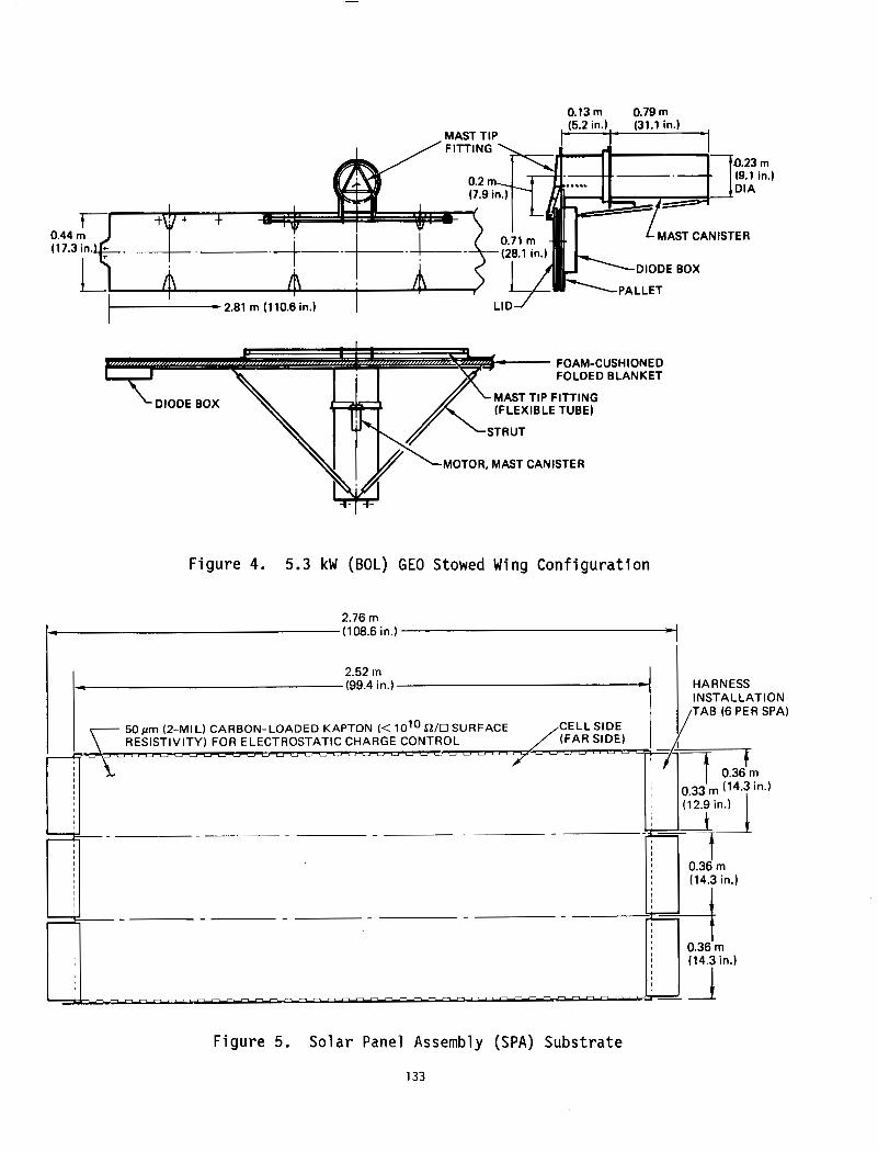
Figures 3 and 4 illustrate the deployed and stowed size for the baseline 5.3 k W (BOL) wing as the result of the Phase IIA prototype detail design study. Two wings of this configuration integrated to opposite sides of a spacecraft provide 10.6 kW (BOL) and 7.6 kW (EOL) power after 10 years in geosynchronous orbit, (GEO). Overall deployed wing dimensions are 16.3-m (642-in.) long (measured
123
from the inboard end of the mast canister at the spacecraft interface to the lid) by 2.8-m (110-in.) wide with a blanket size of 15.3 by 2.7 m (600 by 108-in.).
Blanket Assembly
The basic blanket substrate material is carbon-loaded Kapton polyimide film 50-pm (2-mils) thick (commercially available from DuPont under the name XCIO’o, which refers to the surface resistivity of the material). The resistivity of the material is sufficiently low to permit grounding of the blanket substrate to prevent electrostatic charge buildup from GEO substorm environments, but sufficiently high to prevent shorting of the solar cell strings.
The 5.3-kW (BOL) blanket is accordion folded into 42 panels, 39 of which are covered with solar cell modules. The blanket consists of 13 three-panel solar panel assemblies (SPA) and two blank leader assemblies (one leader consists of one panel; the other has two panels). Figure 5 illustrates details of the SPA. Nominal panel size is 2.5 x 0.36 m (99.4 x 14.3 in.), exclusive of 0.12-m (4.6-in.) wide extensions bonded along each longitudinal edge where the electrical harness runs are installed. The inter-SPA hingelines are unreinforced heat-set crease folds in the Kapton material. Each SPA is linked to the next SPA through a piano hinge constructed along each outer lateral edge of the SPA. The hinge pin is a pultruded graphite/epoxy rod 1.3 mm (50 mils) in diameter.
Blanket Housing Assembly
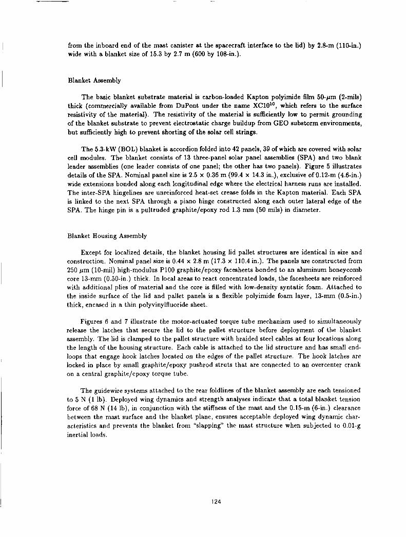
Except for localized details, the blanket housing lid pallet structures are identical in size and construction. Nominal panel size is 0.44 x 2.8 m (17.3 x 110.4 in.). The panels are constructed from 250 pm (10-mil) high-modulus PlOO graphite/epoxy facesheets bonded to an aluminum honeycomb core 13-mm (0.50-in.) thick. In local areas to react concentrated loads, the facesheets are reinforced with additional plies of material and the core is filled with low-density syntatic foam. Attached to the inside surface of the lid and pallet panels is a flexible polyimide foam layer, 13-mm (0.5-in.) thick, encased in a thin polyvinylfluoride sheet.
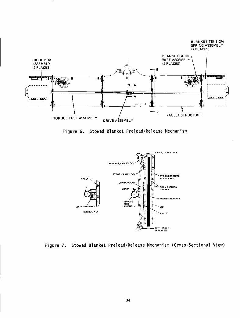
Figures 6 and 7 illustrate the motor-actuated torque tube mechanism used to simultaneously release the latches that secure the lid to the pallet structure before deployment of the blanket assembly. The lid is clamped to the pallet structure with braided steel cables at four locations along the length of the housing structure. Each cable is attached to the lid structure and has small end- loops that engage hook latches located on the edges of the pallet structure. The hook latches are locked in place by small graphite/epoxy pushrod struts that are connected to an overcenter crank on a central graphite/epoxy torque tube.
The guidewire systems attached to the rear foldlines of the blanket assembly are each tensioned to 5 N (1 lb). Deployed wing dynamics and strength analyses indicate that a total blanket tension force of 68 N (14 lb), in conjunction with the stiffness of the mast and the 0.15-m (6-in.) clearance between the mast surface and the blanket plane, ensures acceptable deployed wing dynamic char- acteristics and prevents the blanket from “slapping” the mast structure when subjected to 0.01-g inertial loads.
124

Blanket Deployment System
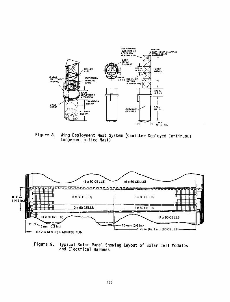
Figure 8 illustrates the mast system. It is a canister-deployed continuous longeron lattice mast similar in configuration to that used on the SAFE I and Olympus solar array wings. A major development under the APSA program was to weight-optimize the design of the mast system, especially the canister structure and deployment mechanism. The mast system was sized to meet 0.10 Hz and 0.01 g wing stiffness/strength requirements. The 0.21-m (8.2-in.) diameter mast is constructed from fiberglass (longerons and battens) except for the stainless steel braided cable diagonals. The stowage canister is aluminum.
Solar Cell Module
Each cell-covered panel contains eight rows of 2 x 4 cm cells with each row containing 120 cells (fig. 9). There are 37,440 cells per blanket assembly. The solar cell stack consists of: (a) 50-pm (Zmils) thick ceria-doped coverglass coated on the front surface with a UV-rejection filter and an enhanced emittance filter to reduce the operating temperature of the cell; (b) 55-pm (2.2-mil) thick 10 R-cm boron-doped back surface field, aluminum back surface reflector, polished silicon solar cell ( ~ 0 = 13.5 percent at 28OC AMO); (c) two inplane stress relief loop silver plated Invar interconnectors soldered to the solar cell in a front/back fashion; and (d) DC93500 silicone adhesive bondlines to attach the coverglass to the solar cell and the solar cell stack to the carbon-loaded Kapton substrate. Operating temperature of the solar cell ranges from 27OC (BOL) to 32OC (EOL). Panel packing factor for cell installation is 0.84 (-1100 cells per m2) exclusive of the electrical harness regions.
The three-panel SPA circuit configuration is illustrated in figure 10 and its features are sum- marized in table 1. Cells and electrical circuits are arranged on the SPA to create mirror-imaged geometry with respect to the longitudinal centerline of the SPA to minimize current-induced mag- netic field effects. Cell rows are arranged in a serpentine manner so string turnaround occurs at the center and the string returns to the outer edge of the panel. An electrical circuit module consists of a single parallel cell by 360 cells in series to obtain a nominal voltage of 150V (EOL). An SPA contains eight circuits, four each on the left- and right-hand sides of the SPA. A 5.3-kW (BOL) blanket assembly contains 104 circuits (13 SPAs). All positive and negative terminations for each circuit occur along the outside edge of the SPA adjacent to the printed circuit harness segment that is bonded to the 0.12-m (4.6-in.) extensions of the basic blanket substrate. All electrical connections in the series circuit as well as between the circuit and harness are soldered.
Electrical Harness
Electrical power is collected via flexible printed-circuit Kapton-insulated copper harnesses. The harness runs from the outboard leader panel to a diode box on the underside of the pallet structure. The harness is bonded to the cell side of the blanket to permit direct access to the solar cell circuit terminations located along the outer edge of the main substrate. Because the blanket is assembled from a number of discrete SPAs and leader panels, the harness is segmented to conform to the indi- vidual SPAs. At each piano hingeline, the adjacent end of each harness segment is brought together to form a “cusp”-shaped fold and is soldered together. In between these locations where the blanket panels are crease-folded to form a hingeline, the harness segment is designed with sufficient length to permit a “cusp” fold in the segment.
125
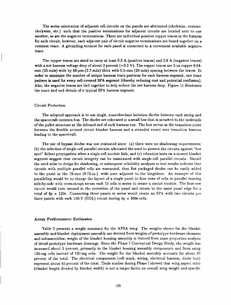
The series orientation of adjacent cell circuits on the panels are alternated (clockwise, counter- clockwise, etc.) such that the positive terminations for adjacent circuits are located next to one another, as are the negative terminations. There are individual positive copper traces in the harness for each circuit; however, each adjacent pair of circuit negative terminations are bused together on a common trace. A grounding turnout for each panel is connected to a convenient available negative trace.
The copper traces are sized to carry at least 0.3 A (positive traces) and 0.6 A (negative traces) with a net harness voltage drop of about 2 percent (-3.2 V). The copper traces are 2-02 copper 0 .64 mm (25-mils) wide by 6&pm (2.7-mils) thick with 0.5-mm (20-mils) spacing between the traces. In order to minimize the number of unique harness trace patterns for each harness segment, one trace pattern is used for every cell-covered SPA segment (thereby reducing cost and potential confusion). Also, the negative traces are tied together to help reduce the net harness drop. Figure 11 illustrates the trace and end details of a typical SPA harness segment.
Circuit Protection
The adopted approach is to use single, nonredundant isolation diodes between each string and the spacecraft common bus. The diodes are colocated in a small box that is attached to the underside of the pallet structure a t the inboard end of each harness run. The box serves as the transition point between the flexible printed circuit blanket harness and a stranded round wire transition harness leading to the spacecraft.
The use of bypass diodes was not evaluated since: (a) there were no shadowing requirements; (b) the selection of single-cell parallel circuits alleviated the need to protect the circuits against “hot spot” failure propagation when a single-cell module fails, and (c) vibration tests on a stowed blanket segment suggest that circuit integrity can be maintained with single-cell parallel circuits. Should the need arise to design for shadowing, or subsequent reliability analyses or test results indicate that circuits with multiple parallel cells are warranted, then flat packaged diodes can be easily added to the panel in the 19-mm (0.75-in.) wide zone adjacent to the hingelines. An example of this paralleling would be to change the layout of a single panel to four rows of cells in parallel running side-by-side with cross-straps across each 10 cells in series to create a circuit module. The four-row circuit would turn around at the centerline of the panel and return to the same panel edge for a total of 4p x 120s. Connecting three panels in series would create an SPA with two circuits per three panels with each 150-V (EOL) circuit having 4p x 360s cells.
Array Performance Estimates
Table 2 presents a weight summary for the APSA wing. The weights shown for the blanket assembly and blanket deployment assembly are derived from weights of prototype hardware elements and subassemblies; weight of the blanket housing assembly is derived from mass properties analysis of detail prototype hardware drawings. Since the Phase I Conceptual Design Study, the weight h a s increased about 5 percent, primarily in the blanket housing assembly components and from using 150-mg cells instead of 130-mg cells. The weight for the blanket assembly accounts for about 50 percent of the total. The electrical components (cell stack, wiring, electrical harness, diode bos) represent about 45 percent of the total. n a d e studies during Phase I showed that wing aspect ratio (blanket length divided by blanket width) is not a major factor on overall wing weight and specific
126

power performance. The flatness of the curves for wing weight versus aspect ratio (over an aspect ratio range from 2 to 10) suggests that the wing width should be as wide as possible consistent with stowage constraints, interference issues relative to other deployed appendages or sensor fields-of-view, and manufacturing/handling limitations.
Table 3 summarizes the predicted performance in comparison to the original program goals. The changes in performance are indicated between the Phase I conceptual design and the present estimates based on updated design drawings, revised analyses, and actual hardware fabrication. Essentially, all design goals have been met. The 10.6 kW (BOL) array has a 10-year GEO EOL power output of 7.6 kW. Including a 10 percent contingency for weight and power output uncertainties, the BOL specific power and power density (based on total panel area) are 132 W/kg and 136 W/mZ, respectively. Corresponding EOL values are 95 W/kg and 97 W/m2.
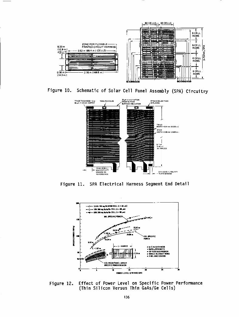
Figure 12 shows the impact of power level on specific power performance for two cell types: (a) the thin silicon cell, and (b) the thin gallium arsenide on germanium cell (GaAs/Ge). Power growth (or reduction) is achieved by adding (or moving) SPAs from the blanket assembly, with appropriate redesign of the electrical harness and resizing of the mast system. The blanket housing assembly would remain virtually unchanged. At higher power levels with comparable deployed stiffness and strength, the specific power performance improves. Even at low power levels, the specific performance is two-to-three times higher than for rigid panel arrays. The figure also shows that advanced planar cells such as GaAs/Ge must be thin (-0.80 pm or 3 mils) and have conversion efficiencies above 18 percent to provide specific power performance comparative to that using thin silicon cells, even though the wing length is reduced about 25 percent. This is because advanced cells such as GaAs/Ge (or InP) are made from substantially denser materials than silicon.
Figure 13 depicts the impact of cell efficiency and cell technology on array specific power, both for thin discrete cells and for “thin-film” devices. Trend lines are shown for the “thin-film” devices with and without the need for a 50-pm (2-mil) coverglass. The upper lefthand corner of the figure illustrates that thin advanced discrete cells such as GaAs/Ge will only provide a %to- 35 percent improvement in specific power performance. The lower righthand region of the figure shows the potential impact for the “thin-film” devices assuming they can be shown to have good stability against the natural radiation environment. EOL specific power of 200 to 250 W/kg may be achievable with the prospect of significant array cost reduction and the potential for even lighter- weight deployment concepts and greater packaging efficiency. Although not envisioned as a near-term item, these thin-film devices exhibit the potential for dramatically opening up new photovoltaic solar power space applications at performance levels approaching the far-term APSA goal of 300 W/kg POL)
Current Program Status
Prototype Wing Development
Figure 14 shows the configuration of the prototype wing that is now under construction. Its design is based on the 5.3 k\Y (BOL) wing described in the previous sections. The prototype is identical to the full-power wing except in four respects: (a) it is truncated in length, consisting of a blanket assembly with two 3-panel SPAs and two 1-panel leader panels; (b) the live solar cell modules are mechanical representations of flight-quality cells/covers (the covers are uncoated ceria- doped glass rather than being coated and the cells are electrically active, but do not possess high
127

electrical performance characteristics); (c) construction is being done to standards consistent with the prototype nature of the hardware rather than to flight-quality standards; and (d) the electrome- chanical actuators to activate the blanket housing preload/release mechanism and for deploying the mast are not ff ight-qualified.
The SPAS are covered with 1440 2 x 4 em live thin silicon solar cell modules interconnected together to obtain a series of high voltage circuits ranging from 50 V (120 cells in series) to 150 V (360 cells in series), with the rest of the SPA area covered with masssimulated aluminum chips. Along both edges of the 8-panel blanket assembly are installed flexible printed circuit harnesses running from the outboard leader panel to diode boxes on the pallet structure. The solar cell circuits tie into the electrical harness on one edge of the blanket. The mast system is full scale in terms of the canister system, but with a truncated length of mast (4.5m or 15 ft instead of 15.3 m or 50 ft). The blanket housing assembly is full scale with representative mechanisms for preload and release of the stowed blanket.
The design of prototype wing hardware is completed with the release of engineering drawings to manufacturing for construction of the blanket assembly and deployment mast system. Fabrication of the blanket housing assembly and wing integration are deferred to Phase IIB of the program. Fabrication of the blanket assembly substrate is completed as well as the electrical harness segments. The electrical harness segments have been installed and the live and mass-simulated cell modules are presently being installed. The harness segments were fabricated by MINCO of Minneapolis, MN. Thin silicon cells were obtained from all three major domestic suppliers (Solarex, Spectrolab, ASEC). The cells are divided into three weight groups (130, 150, and 170 mg) to evaluate which will be the minimum weight cell that is mechanically compatible with installation on a flexible blanket substrate when subjected to handling and launch loadings and deployment movements. This weight range can have a 4 percent swing on wing weight and specific power. Coverglass (CMZ and CMZDG) was obtained from Pilkington in England. The measured weight of the blanket assembly was very close to that predicted from mass properties analysis of engineering drawings and weighing of constituent
. elements.
Work is nearing completion on the fabrication and assembly of the mast structure and canister system. The hardware was designed and built by AEC-Able Engineering, Goleta, CA. The as- manufactured weight is very close to that estimated from analysis of engineering drawings. Strengths and stiffness tests on the mast are planned in the near future as are functional deployment/retraction and system-level strengh/ stiffness tests when the mast-canister hardware is fully integrated.
Component Tests
To support the prototype design development, two component-level tests were conducted to obtain data on the performance of key aspects of the design: (a) load-relaxation tests on the poly- imide foam material used to cushion the stowed blanket assembly; and (b) vibration tests on stowed cell-covered SPA sections to evaluate the effectiveness of the stowed blanket protection scheme to prevent unacceptable damage to the solar cell modules.
The results from the load-relaxation tests indicate that after long-term storage ( 6 months to 1 year under 7000 to 14000 Pa [-1 to 2 psi] of initial preload stowage pressure), at least TO to 75 percent of the initial preload pressure would remain. This fact, coupled with the stowed vibration component test results, indicates that the TA301 polyimide foam would be acceptable for use as launch protection for the stowed folded blanket assembly.
128

A series of 21 stowec. vibration tests were completed on an 8-panel, 0.3-m (12-in.) wL.2 section of the prototype blanket assembly containing 348 glassed, interconnected thin silicon solar cells (from Solarex) and 228 mass-simulated aluminum chips. One panel was filled with “light” (-130 mg) cells glassed with 50-pm (2-mil) thick CMX and CMZ ceria-doped glass covers. On the opposing panel, “heavy” (-170 mg) cells were placed with CMX and CMZ covers. The other two central panels were covered with “medium” weight (-150 mg) cells with CMX and CMZ covers. The remaining SPA panels were covered with mass-simulated aluminum chips. Prior to the first series of stowed vibration tests, visual and infrared camera inspection revealed about 10 percent of the total covers were cracked and about 5 percent of the total cells were cracked, with the predominance of damage to the CMX covers and 130- to 150-mg cells. After a series of 15 one-minute duration vibration tests in multiple axes ranging from 10 to 30 gs (rms) (representative of simulated shuttle vibroacoustic launch environments) at a nominal stowage pressure of 7000 Pa (- 1 psi), an additional 14 percent of the covers had cracked and an additional 3 percent of the cells had cracked. Under a subsequent series of 6 stowed one-minute duration vibration tests in multiple axes ranging from 20 to 30 gs (rms) at a nominal stowage pressure of 3500 Pa (-0.5 psi), an additional 3 percent of the covers cracked with no additional cell damage. Cover damage was primarily in the CMX material, implying that the CMZ material is more crack resistant and should be the baseline coverglass material. More damage occurred to the 130 mg cells than to the 150 or 170 mg cells. The difference in percentage damage between the 150 and 170 mg cells was small; hence, 150 mg cells were selected as the baseline cell for the prototype wing. In no instance did any damage to the cells result in open circuits. Examination of the cell/cover damage also revealed: (a) once a cell cracked, no new cracks developed or existing cracks propagated in the cell; (b) in only a few instances did the cover and cell crack in the same cell stack; and (c) in only a few instances did a crack occur both in the cover and cell of a cell stack during the same test.
References
[ 11 R. M. Kurland et a], “Advanced Photovoltaic Solar Array Design,” 22nd IECEC Conference Proceedings, vol I, Aug. 1987, pp. 103-114.
[ 21 Solar Array Flight Ezpen’ment (SAFE I) Final Report, LMSC Document F087173, Apr. 1986.
[ 31 L. Gerlach et al, “The Design of the GSat (Olympus) Solar Array,” 3rd European Symposium on Photovoltaic Generators in Space Proceedings, May, 1982, p. 241.
129
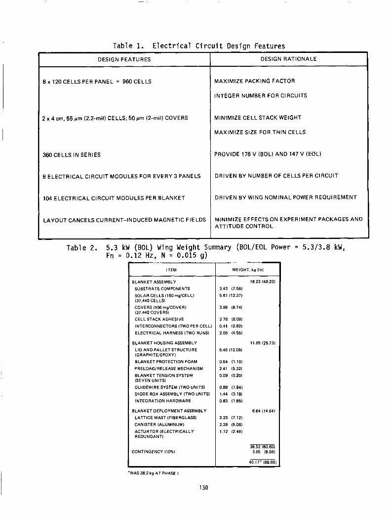
Table 1. E l e c t r i c a l C i r c u i t Design Features
-_ ... --.-- WEIGHT, kg (Ib)
- 18.23 (40.23)
3.43 (7.56)
5.61 (12.37)
3.96 (8.74)
2.76 16.09) 0.41 10.92) 2.06 (4.55)
11.65 (25.731
5.46 (12.051
0.54 (1.19) 2.41 (5.32)
0.09 (0.20)
0.88 (1.94)
1.44 (3.181
0.83 0.85)
6.64 (14.64) 3.23 (7.12)
2.29 (5.06)
1.12 (2.46)
36.52 (80.60) 3.65 (8.061
40.17. (88.66)
DESIGN FEATURES
8 x 120 CELLS PER PANEL = 960 CELLS
2 x 4 cm, 55 prn (2.2-mil) CELLS; 50 pm (2-mil) COVERS
360 CELLS IN SERIES
8 ELECTRICAL CIRCUIT MODULES FOR EVERY 3 PANELS
104 ELECTRICAL CIRCUIT MODULES PER BLANKET
LAY 0 UT CANCE LS CU R RENT- I N DUCE D MAG N ET I C F I E LDS
ITEM
BLANKET ASSEMBLY SUBSTRATE COMPONENTS SOLAR CELLS (150 mg/CELL) 137,440 CELLS) COVERS (106 mg/COVER) (37.440 COVERS) CELL STACK ADHESIVE INTERCONNECTORS (TWO PER CELL)
ELECTRICAL HARNESS (TWO RUNS)
BLANKET HOUSING ASSEMBLY LID AND PALLET STRUCTURE (GRAPHITE/EPOXY)
BLANKET PROTECTION FOAM PRELOAD/RELEASE MECHANISM BLANKET TENSION SYSTEM (SEVEN UNITS)
GUIDEWIRE SYSTEM (TWO UNITS)
DIODE BOX ASSEMBLY (TWO UNITS) INTEGRATION HARDWARE
BLANKET DEPLOYMENT ASSEMBLY LATTICE MAST (FIBERGLASS) CANISTER (ALUMINUM)
ACTUATOR (ELECTRICALLY REDUNDANT)
CONTINGENCY (10%)
DES I G N RAT I ON A LE _ _ _ _ _ ~
MAXIMIZE PACKING FACTOR
INTEGER NUMBER FOR CIRCUITS
MINIMIZE CELL STACK WEIGHT
MAXIMIZE SIZE FOR THIN CELLS
PROVIDE 176 V (BOL) AND 147 V (EOL)
DRIVEN BY NUMBER OF CELLS PER CIRCUIT
DRIVEN BY WING NOMINAL POWER REQUIREMENT
MINIMIZE EFFECTS ON EXPERIMENT PACKAGES AND ATTITUDE CONTROL
'WAS 38.2 kg AT PHASE I
130

Table 3. So la r Array Performance Summary, 10-Year Geosynchronous Mission
Parameter
801 power (GEO)
EO1 power IGEO1
801 spaifii power at equinox
EO1 rpecifii power at equinax
EO1 power density at equinox
801 OX. voltage
Wing weight
Deployed frequency
Oeployed stiffness
'Includes 10 percent weight con1 "Based on total pand area with
1986 God ICR 9573581
10 kW (2 wings)
Not specifird; 8 kW implid by EO1 spaifii powM god
>130 W K g
>lo5 WKp
>I IO WIM~; referwr area not specifid
<200 volts
Not rpecifd
>0.01 HI; 0.1 HZ preferred
X.001 g; 0.01 g preferred
iencv ness
PHASE
I DESIGN TRADES CONCEPTUAL DESIGNS PRELIMINARY DESIGN REPORT
DETAIL DESIGN COMPONENT OEV. TESTS BLANKET FAB. MAST SYSTEM FAB. INTERIM REVIEW
BOX SYSTEM FAB. WING INTEGRATION FUNCTIONAL TESTING WING UPGRADE FUNCTIONAL TESTING INTERIM REVIEW
TESTING FINAL REPORT
IIA PROTOTYPE WING OEVELOPEMNT
118 PROTOTYPE WING DEV. (CONT')
111 PROTOTYPE DEMONSTRATION
CY 1985
qqqi &
-
PhurI 1988 Estinute ICR 957358)
10.4 kW
1.4 kW
136.1 WKg'
96.7 WKp'
94.6 W d "
210 vdts
38.2 Kg'
0.10 Hz
0.015 g
~~ ~
PhurIIA 1988 Estimta (CR 9579901
10.6 kW
7.6 kW
131.5 WKg'
94.5 WKp'
97.4 WIM2"
214 vdts
40.2 Kg'
0.14 Hz bending) 0.12 Hz Itorsionl
0.015 g
.'.= =r'; PLANNED, BUT
F igure 1. Development Schedule
131

BLANKET TENSIONING SYSTEM
-LID
TT 2.76 'm (108.6 in.) BLANKET WIDTH 2.81 m
(110.6 in.) LID AND PALLET LENGTH
LID
Figure 2. Generic Wing Conf igura t ion (Rear Side Shown)
e 15.25 m (600.6 in.) FOR 39-CELL-COVERED PANEL BLANKET PLUS 3 LEADER PANELS 7
p-0.36 m (14.3 in.) PANEL
-.- . .....,.....,.......... ........................ ...,.....,..... 1. ......... I I I I
CIRCUIT H A R N E S ~ (2 PLACES)
8 CIRCUITS PER 3 PANELS
_.._ I .... IIII .... L...
I I
L
DIODE I BOX
0.15m ( 6 . 0 i n . d 1- SOLAR PANEL ASSEMBLY (13 REQUIRED)
Figure 3. 5.3 kW (BOL) GEO Deployed Wing Conf igura t ion
132
0.13 m 0.79m
0.44 MAST CANISTER (17.3
MAST TIP FITTING (FLEXIBLE TUBE)
Figure 4. 5.3 kW (BOL) GEO Stowed Wing Conf igura t ion
2.76 rn
HARNESS INSTALLATION
/TAB (6 PER SPA)
7 0.36 rn 1.33 rn (14.3 in.)
0.36 rn (14.3 in.)
i 0.36 rn
(14.3 in.)
F igure 5. So la r Panel Assembly (SPA) Substrate
133
BLANKET TENSION SPRING ASSEMBLY (7 PLACES)
BLANKET GUIDE WIRE ASSEMBLY
Figure 6. Stowed Blanket Preload/Release Mechanism
PALLET.
SECTION A-A
LATCH, CABLE LOCK
BRACKET. CABLE LOCK
STAINLESS STEEL STRUT. CABLE LOCK
FOAM CUSHION
FOLDED BLANKET
SECT4ON 8-6
Figure 7. Stowed B lanket Preload/Release Mechanism (Cross-Sect ional V i e w )
134
0.36 mm 10.014 in.) DIA DIAGONAL ISTEEL CABLE)
3.58 x 4.08 mm 10.14 x 0.16 in.)
Figure 8. Wing Deployment Mast System (Canister Deployed Continuous Longeron Lattice Mast)
(6 x 60 CELLS) (6 x 60 CELLS)
-15 mm 10.6 in.) . - .._I ... I-".
w 0 . 1 2 rn (4.6 in.) HARNESS RUN
Figure 9. Typical Solar Panel Showing Layout o f Solar Cell Modules and Electrical Harness
135
PRINTED CIRCUIT HARNESS ZONE FOR FLEXIBLE
-2.52 m (99.4 in.) (CELLS)--, 1 0.33 m (12.9 in.) ,_=, ,
114.3 in.)
F igure 10. Schematic o f So lar
TRACE THICKNESS-? 01 TOOLING HOLES (UIw I-?llmillCOPPER I /
REVERSE SIDE
6 CELL
C e l l Panel Assembly (SPA) C i r c u i t r y
X p m I1 mill KAPTON
SURFACE INSULATION / '2PLACEs1 STRAIN RELIEF PADS ,FRONT& REAR
... ... I + - ; L A T E WINDOW
F igure 11. SPA E l e c t r i c a l Harness Segment End D e t a i l
6.N
113 k S T l ~ F N E P e U J l S g STRENCTM
1B VEAR E t 0 MISSION
1 N I L cy2 COVERS 1 1 4 1 UNSLE BLANKET WINS
S?ECIFIC WWER REflON B I I I 1 I J
C 0 1S n n 3B Wtl LEVEL U W I N W LWI
F igure 12. E f f e c t o f Power Level on S p e c i f i c Power Performance (Thin S i l i c o n Versus Thin GaAs/Ge C e l l s )
136

0 1 I I I 1 1 I I 1 I I 80 100 120 140 160 180 200 220 240 260 280 300
EOL SPECIFIC POWER (W/kg) (WITH 10% CONTINGENCY)
Figure 13. Impact o f Advanced C e l l Technology on So lar Array S p e c i f i c Power, 10-Year Geosynchronous Mission
0.36 rn (14.3 in.)
F igure 14. Base1 i n e Prototype Wing Configuration
137


![An Adaptive Solar Photovoltaic Array Using Model-Based ......2) The local hot spot in the shaded part of the solar PV array can damage the solar cells [7]. There are several approaches](https://img.pdfslide.us/doc/110x75/5f155d1cad09a87aff0b5cff/an-adaptive-solar-photovoltaic-array-using-model-based-2-the-local-hot.jpg)