Embed Size (px)
Citation preview

© 1999-2016 AGG Software
PRINTED MANUAL

All rights reserved. No parts of this work may be reproduced in any form or by any means - graphic, electronic, ormechanical, including photocopying, recording, taping, or information storage and retrieval systems - without thewritten permission of the publisher.
Products that are referred to in this document may be either trademarks and/or registered trademarks of therespective owners. The publisher and the author make no claim to these trademarks.
While every precaution has been taken in the preparation of this document, the publisher and the author assume noresponsibility for errors or omissions, or for damages resulting from the use of information contained in thisdocument or from the use of programs and source code that may accompany it. In no event shall the publisher andthe author be liable for any loss of profit or any other commercial damage caused or alleged to have been causeddirectly or indirectly by this document.
Printed: 29.11.2016
Advanced NMEA Data Logger
© 1999-2016 AGG Software
Publisher
AGG Software
Production
© 1999-2016 AGG Softwarehttp://www.aggsoft.com

IContents
© 1999-2016 AGG Software
Table of Contents
Part 1 Introduction 1
................................................................................................................................... 11 About Advanced NMEA Data Logger
................................................................................................................................... 22 Glossary
Part 2 License, Registration andtechnical support 4
................................................................................................................................... 41 License
................................................................................................................................... 52 Limitations
................................................................................................................................... 63 How to register
................................................................................................................................... 64 Support
Part 3 Installation 6
................................................................................................................................... 61 System requirements
................................................................................................................................... 72 Installation process
Part 4 Program use 7
................................................................................................................................... 71 Getting started
................................................................................................................................... 92 Introduction
................................................................................................................................... 113 Data flow diagram
................................................................................................................................... 124 Work complete
................................................................................................................................... 125 Useful advices
................................................................................................................................... 136 Configuration
......................................................................................................................................................... 13Serial port
.................................................................................................................................................. 13Serial (COM) port
......................................................................................................................................................... 18Network connection
.................................................................................................................................................. 18TCP/IP settings
......................................................................................................................................................... 26Additional parameters
.................................................................................................................................................. 26Data view change
.................................................................................................................................................. 28Date/time configuration
.................................................................................................................................................. 29Name and security
......................................................................................................................................................... 31Log files
.................................................................................................................................................. 31Log rotation
.................................................................................................................................................. 33Log f ile access
.................................................................................................................................................. 34Log deletion
......................................................................................................................................................... 35Modules
.................................................................................................................................................. 35Introduction & setup
.................................................................................................................................................. 39OPC server
.................................................................................................................................................. 42NMEA data parser
........................................................................................................................................... 42Introduction
........................................................................................................................................... 43Common parameters
........................................................................................................................................... 44NMEA sentences parser
........................................................................................................................................... 45Supported talkers
Advanced NMEA Data LoggerII
© 1999-2016 AGG Software
........................................................................................................................................... 46Supported sentences
................................................................................................................................... 547 Program options
......................................................................................................................................................... 54Window view
......................................................................................................................................................... 56Date/time stamp view
......................................................................................................................................................... 57Protocol and errors handling
......................................................................................................................................................... 58Service mode on Windows 2000+
.................................................................................................................................................. 58Configuration
.................................................................................................................................................. 62Window s Vista+ notes
......................................................................................................................................................... 63Restart & Security
Part 5 Serial communications overview 0
................................................................................................................................... 01 RS-232
................................................................................................................................... 02 DB9 (9 pin) RS-232 port pinout
................................................................................................................................... 03 DB25 (25 pin) RS-232 port pinout
................................................................................................................................... 04 RS-232 loopback devices
................................................................................................................................... 05 RS-232 data transfer cables
Part 6 Having problems? 64
................................................................................................................................... 641 Program doesn't run or work
................................................................................................................................... 652 FAQ

1Introduction
© 1999-2016 AGG Software
1 Introduction
1.1 About Advanced NMEA Data Logger
Advanced NMEA Data Logger inputs NEAM data stream from GPS, navigation or any other NMEAcompatible device directly into file, Excel, Access, database or any Windows application. AdvancedNMEA Data Logger provides real-time data collection from any device or instrument.
Advanced NMEA Data Logger captures serial or network data, custom parses it to your needs, thenextract bits of data from data packets and transfers the data to any Windows or DOS application -either by sending keystrokes to the application's window, by passing the data through DDE(Dynamic Data Exchange) conversations, ODBC, OLE.
Key features of Advanced NMEA Data Logger is:
capability to log multiple ports at the same time. Each port may have fully different settings.supports all talker types (GPS, Heading, Velocity sensors etc).captures all standard NMEA sentences and some proprietary sentences for Garmin, SiRFandStarLink devices.supports custom baudrates.supports date/time stamping;supports aggregation of multiple sentences to one data record.outputs received data without any changes to a log file.advanced data parsers that allows you to parse, filter and format your source data.data export to ready-to-use MS Excel files.data export to any ODBC-compatible database (MS SQL, Oracle, MS Access, dBase andothers).Advanced NMEA Data Logger can run as DDE or OPC server and can export all received data.Advanced NMEA Data Logger can use direct connection (use OLE) to Microsoft Excel and writedata directly to rows or columns.program messages logging.simple, menu-driven step by step set-up - programming is not required to configure the softwareto collect data.many plug-in modules that extending program features. Supporting various operating systems. It runs under all versions starting from Windows 2000,including 32 and 64-bit systems..
Advanced NMEA Data Logger also transmits requests or commands over a network connection orserial port to control or query your instruments directly from Advanced NMEA Data Logger overASCII protocol.
Unlike most other serial logging applications, Advanced NMEA Data Logger can run as a service sothat it starts as soon as the operating system starts and doesn't require a user to log in and run it. Itwill continue to run even as users logon and logoff the workstation.
It is extremely easy to use! The configuration process is fully menu driven and has complete,context sensitive, on-line help. you can easily customize all input to your exact specifications. Onceyou see how easy it is to use Advanced NMEA Data Logger, you will never again take data readingsby hand!
Typical usage

2 Advanced NMEA Data Logger
© 1999-2016 AGG Software
A typical application for Advanced NMEA Data Logger is to log and aggregate data from one or moreNMEA devices to disk or a software replacement for a hardware data logger.
Applications examples
Data logging systems;Remote control systems;Remote control of displays and signalling.
Company home page: http://www.aggsoft.com/Software home page: http://www.aggsoft.com/nmea-data-logger.htm
1.2 Glossary
ASCII - An acronym for American Standard Code for Information Interchange. ASCII files are plain,unformatted text files that are understood by virtually any computer. Windows Notepad and virtuallyany word processor can read and create ASCII files. ASCII files usually have the extension .TXT (e.g., README.TXT).
Binary File - A file that contains data or program instructions written in ASCII and extended ASCIIcharacters.
Bit - Binary digit in the binary numbering system. Its value can be 0 or 1. In an 8-bit characterscheme, it takes 8 bits to make a byte (character) of data.
Bytes - A collection of eight bits that represent a character, letter or punctuation mark.
Cable - Transmission medium of copper wire or optical fiber wrapped in a protective cover.
Client/Server - A networking system in which one or more file servers (Server) provide services;such as network management, application and centralized data storage for workstations (Clients).
COM port - Short for a serial communication port. Most serial communication softwarecommunicate with a computer through a communication port, and most IBM and IBM-compatiblecomputers support up to four serial ports COM1, COM2, COM3 and COM4. Additional ports can beadded by adding additional hardware.
Data bits - A group of bits (1's and 0's) that represent a single character or byte. Typically, there areseven or eight data bits. During an asynchronous communication (e.g., BitCom connecting toCompuServe), each side must agree on the number of data bits. Data bits are preceded by a startbit and followed by an optional parity bit and one or more stop bits.
DNS (Domain Name System) - A DNS server lets you locate computers on a network or theInternet (TCP/IP network) by domain name. The DNS server maintains a database of domain names(host names) and their corresponding IP addresses. PC aggsoft's IP address, 198.63.211.24,corresponds to the DNS name www.aggsoft.com.
Flow control - A method of controlling the amount of data that two devices exchange. In data

3Introduction
© 1999-2016 AGG Software
communications, flow control prevents one modem from "flooding" the other with data. If data comesin faster than it can be processed, the receiving side stores the data in a buffer. When the buffer isnearly full, the receiving side signals the sending side to stop until the buffer has space again.Between hardware (such as your modem and your computer), hardware flow control is used;between modems, software flow control is used.
Handshaking - Is the way in which the data flow between computers/hardware is regulated andcontrolled. Two distinct kinds of handshaking are described: Software Handshaking and HardwareHandshaking. An important distinction between the kinds of signals of the interface is between datasignals and control signals. Data signals are simply the pins which actually transmit and receive thecharacters, while control signals are everything else.
Internet - A global network of networks used to exchange information using the TCP/IP protocol. Itallows for electronic mail and the accessing ad retrieval of information from remote sources.
IP, Internet Protocol - The Internet Protocol, usually referred to as the TCP/IP protocol stack,allows computers residing on different networks to connect across gateways on wide-area networks.Each node on an IP network is assigned an IP address, typically expressed as 'xx.xx.xx.xx'.
IP address (Internet Protocol address) - The address of a computer attached to a TCP/IPnetwork. Every client and server station must have a unique IP address. Client workstations haveeither a permanent address or one that is dynamically assigned to them each dial-up session. IPaddresses are written as four sets of numbers separated by periods; for example, 198.63.211.24.
LAN (Local Area Network) - A network connecting computers in a relatively small area such as abuilding.
NIC, Network Interface Card - A card containing the circuitry necessary to connect a computer toa particular network media. Typically, the NIC plugs into the computer's accessory bus, (PCI, USB,etc.) and provides a network connection such as 10baseFL (fiber ethernet), thin-net, AUI, etc.
PC - abbreviation for a Personal Computer.
Parity - In data communications, parity is a simple procedure of checking the integrity of transmitteddata. The most common type of parity is Even, in which the number of 1's in a byte of data add up toan even number, and None, in which a parity bit is not added.
Ports - A connection point for a cable.
Protocol -A formal description of a set of rules and conventions that govern how devices on anetwork exchange information.
RS232, RS423, RS422 AND RS485 - The Electronics Industry Association (EIA) has producedstandards for RS232, RS423, RS422, and RS485 that deal with data communications. EIAstandards where previously marked with the prefix "RS" to indicate the recommended standard.Presently, the standards are now generally indicated as "EIA" standards to identify the standardsorganization.
Electronic data communications will generally fall into two broad categories: single-ended anddifferential. RS232 (single-ended) was introduced in 1962. RS232 has remained widely used,especially with CNC control builders. The specification allows for data transmission from one

4 Advanced NMEA Data Logger
© 1999-2016 AGG Software
transmitter to one receiver at relatively slow data rates (up to 20K bits/second) and short distances(up to 50' @ the maximum data rate). This 50' limitation can usually be exceeded to distances of200' or more by using low capacitance cable and keeping the data rates down to 9600 baud andlower.
RTS/CTS Hardware handshaking - uses additional wires to tell a sending device when to stop orstart sending data. DTR and RTS refer to these Hardware handshaking lines. you can select whetheryou need to use DTR or RTS individually, or use both lines for hardware handshaking. See also Xon/Xoff.
TCP/IP, Transport Control Protocol / Internet Protocol - TCP and IP are communicationsprotocols, that is, structured languages in which data is communicated between one process andanother, and between one network and another. TCP/IP is implemented in a multi-level layeredstructure.TCP/IP is the 'glue' that that ties together the many heterogeneous networks that make up theInternet.
Stop bits - In data communication, one or two bits used to mark the end of a byte (or character). Atleast one stop bit is always sent.
2 License, Registration and technical support
2.1 License
Copyright © 1999-2016 AGG Software.All Rights Reserved
SOFTWARE LICENSE
Trial Limited Version
The trial limited version of this software may be used for evaluation purposes at the user's own riskfor a trial period. At the end of the trial period, the user must either purchase a license to continueusing the software, or remove it from his/her system.
The trial limited version may be freely distributed, provided the distribution package is not modified.No person or company may charge a fee for the distribution of Advanced NMEA Data Logger withoutwritten permission from the copyright holder.
Licensed Version
On payment of the appropriate license fee, the user is granted a non-exclusive license to use Advanced NMEA Data Logger on one computer (i.e. a single CPU), for any legal purpose, at a time.The registered software may not be rented or leased, but may be permanently transferred, if theperson receiving it agrees to terms of this license. If the software is an update, the transfer mustinclude the update and all previous versions.

5License, Registration and technical support
© 1999-2016 AGG Software
Registered customer are entitled to free updates during one year from the date of purchase. Itmeans that during one year you can download and install the latest registered versions of AdvancedNMEA Data Logger from our site. If you don't want to purchase an updates, you can use theprogram forever; it will never expire, but you won't be able to use the latest version. If you purchasedthe software more than one year ago, you are no longer entitled to free upgrade and technicalsupport; however, you can purchase an updates to the latest version at a special, greatly discountedprice, and this updates will allow you to have free updates and technical support for another year.The type of update license must match the type of your existing license.
Whilst every care has been taken in the construction and testing of this software, it is suppliedsubject to the condition that the user undertakes to evaluate the suitability of the control for his/herpurposes. AGG Software makes no representation of the software's suitability for any purpose, andthe user agrees that AGG Software has no responsibility for any loss or damage occasioned by theuse of this software.
TO THE MAXIMUM EXTENT PERMITTED BY APPLICABLE LAW, THE SOFTWARE ANDDOCUMENTATION ARE PROVIDED "AS IS" AND AGG SOFTWARE DISCLAIMS ALL OTHERWARRANTIES AND CONDITIONS, EITHER EXPRESS OR IMPLIED, INCLUDING, BUT NOTLIMITED TO, IMPLIED WARRANTIES OF MERCHANTABILITY, FITNESS FOR A PARTICULARPURPOSE, CONFORMANCE WITH DESCRIPTION, TITLE AND NON-INFRINGEMENT OF THIRDPARTY RIGHTS.
TO THE MAXIMUM EXTENT PERMITTED BY APPLICABLE LAW, IN NO EVENT SHALL AGGSOFTWARE BE LIABLE FOR ANY INDIRECT, INCIDENTAL, CONSEQUENTIAL, SPECIAL OREXEMPLARY DAMAGES OR LOST PROFITS WHATSOEVER (INCLUDING, WITHOUTLIMITATION, DAMAGES FOR LOSS OF BUSINESS PROFITS, BUSINESS INTERRUPTION,LOSS OF BUSINESS INFORMATION, OR ANY OTHER PECUNIARY LOSS) ARISING OUT OFTHE USE OR INABILITY TO USE THE SOFTWARE PRODUCT, EVEN IF AGG SOFTWARE HASBEEN ADVISED OF THE POSSIBILITY OF SUCH DAMAGES. IN ANY CASE, AGG SOFTWARE'SCUMULATIVE AND ENTIRE LIABILITY TO YOU OR ANY OTHER PARTY FOR ANY LOSS ORDAMAGES RESULTING FROM ANY CLAIMS, DEMANDS OR ACTIONS ARISING OUT OF ORRELATING TO THIS AGREEMENT SHALL NOT EXCEED THE PURCHASE PRICE PAID FORTHIS LICENSE.
Should any term of these terms and conditions be declared void or unenforceable by any court ofcompetent jurisdiction, such declaration shall have no effect on the remaining terms hereof.
If you do not agree to these conditions you should not install this software.
2.2 Limitations
Program is distributed on shareware terms. This means limited and unavailable secondary programpossibilities, which become valuable or available after program registration. To register the programread here .In trial version of our program are the following limits:
Trial period is limited by 21 days. After that time program won't work until it is registered. Continuous program work time is limited. After set period a message will be displayed andprogram stops its work; All data export modules can handle first 100 records only;
6

6 Advanced NMEA Data Logger
© 1999-2016 AGG Software
2.3 How to register
The program is distributed on shareware terms. This signifies limited or unavailable many features ofthe program, getting of full value or available after program registration.
If you'd like to be a registered user, to get information about the release of new versions, to usetechnical support and, at last, to get access to disabled functions of the program, register yourcopy. For registration, please, read license agreement .
If you want to buy a program through the Internet visit the registration page of our site. On this pageyou can get the newest information about the registration process, and also find an order link. Afteryou've have the form of order registration. Enter your personal information and choose the mostconvenient payment method for you. Further, you'll get notification and follow the notes in it.
More information about services, registration documents, payment means you can get on our registration page of our site.
2.4 Support
Technical questions [email protected]
Common questions [email protected]
Sales questions [email protected]
3 Installation
3.1 System requirements
Windows 2000 Professional - Windowsa 8.1, including x64 and x86 OS, Workstation and ServerOS.
It is necessary to have at least one free COM port, not busy by any device (mouse, for example) toconnect external device.It is necessary to have at least one working network interface (card) in your PC.
4

7Installation
© 1999-2016 AGG Software
3.2 Installation process
If any beta-version was installed on your computer, remove it.
Quit of the working Advanced NMEA Data Logger on installation time.
Run an installation file.
By default, Advanced NMEA Data Logger will be installed to the directory "/Programs Files/Advanced NMEA Data Logger" of your system disk, but you can change this path.
In the standard distributive of Advanced NMEA Data Logger are no additional modules files, whichyou can download from our site.
4 Program use
4.1 Getting started
After you have successfully installed Advanced NMEA Data Logger, use the following simple stepsto configure and run it.
Open the Advanced NMEA Data Logger program from the Start Menu.
At program run you get into the main program window (fig. 1.1.1), main elements of which are themain menu, the data window, the program messages list and the status bar. In the data window willbe viewed formatted data processig. In the messages list are logged information, warning and errormessages. The status bar shows current state of the selected data source, interface errormessages and a number of bytes processed. Through the main menu, placed above the datawindow, you can get access to program settings ("Options/Program settings...") and from themenu "File" (fig. 1.1.2) can open an current log-file or clean the data window.
9

8 Advanced NMEA Data Logger
© 1999-2016 AGG Software
Fig. 1.1.1 Main program window
Fig. 1.1.2. "File" menu item
By default (after installation), the program has not any data sources configured. If the list of datasources on the toolbar is empty, then the program will ask you to add new configuration. Otherwise,the program will fill in the list of data sources and try to start logging of data sources configured.Yes, of course, all your settings are being saved while exiting from the program and loaded while theprogram start.
Set-Up is as Easy as 1-2-3
Step 1. Configure one or more data sources.
Click the "Add configuration" button on the toolbar with big green plus and choose communicationparameters for your device. The "COM Port settings" tab of the "Configuration options" dialoglets you configure your settings.
Step 2. Configure log file.
Select the "Log file" header in the configuration dialog window and enable logging for a necessarydata direction.
13

9Program use
© 1999-2016 AGG Software
Step 3. Define how you want the NMEA data to be parsed and translated .
The "Plug-in" button on the toolbar in the main window or "Modules" tab in the dialog window letsyou specify how to parse, filter and format your data to the fit the exact format required by yourapplication. It also lets you pre-define automatic output strings to be sent to an external device.
Now, the program process and exports data from one or multiple data sources.
4.2 Introduction
Program can work with any kind of serial devices. Before configuring our software, the followingconditions should be executed:
Device should have a RS-232 serial port interface (can be also used a RS-485 interface with anadditional hardware converter);Device is configured to send data to serial port with or without requests from a PC side;You know all information about serial port parameters of your device (If your device useshardware or software flow control (please, read your device's data sheet), then you should knowabout flow control type);Device's serial port is connected with computer serial port with a cable (null-modem or otherspecial cable);Computer's COM port, to which your device is connected is not busy, for example by mousesoftware driver.
How to configure port parameters, you can read in the next chapter "Serial port settings ".
Program can work with any kind of network interface cards (NIC). Before configuring our software,the following conditions should be executed:
If your PC has more than one network interface card (NIC) then Advanced NMEA Data Loggerwill display a list of all the IP addresses for each NIC installed in your system so that you canselect the IP Address that you want to use. In order for Advanced NMEA Data Logger to act asa server, the PC that it is running on must have at least one network interface card with an IPaddress assigned to it;If Advanced NMEA Data Logger will work as a server and your PC receives the IP addressdynamically from a DHCP server, then you should ask your network administrator to assign astatic IP address to your PC.
How to configure port parameters, you can read in the next chapter "IP settings ".
Advanced NMEA Data Logger can save data to a log file(s) without any changes (i.e. create rawbinary log files) or write to log files depending on the parser module selected. In the first case youcan view the log file with any hex editor and use this data for further analysis and remaking. In thesecond case you can view data with any text editor. You can find more information about log files inthe "Log rotation " chapter.
You can watch the data in the data window (fig. 1.1.1 ). The data view is fully customizable. Youcan watch data in decimal, hexadecimal or your own format. How to customize data view you canread in the "Data view " chapter and how to customize program view you can read in the "Window
35
13
18
31
7
26

10 Advanced NMEA Data Logger
© 1999-2016 AGG Software
view " chapter.
The data can be exported or transferred to one or more targets. Most simple way is to configure thelog file rotation. But it is small part of all features of Advanced NMEA Data Logger. Advanced NMEAData Logger has many additional modules (so-called plug-ins), that are appreciably extendingpossibilities of the logging software. You can download and install any module supported. Mostmodules are free of charge for our customers. How to install and configure modules you can read inthe "Modules " chapter.
The program and their plug-ins generates many messages and writes they to the list in the mainwindow (fig. 1.1.1 ) and a protocol file, that you can use for administration of the software. Youcan configure types of system messages. More information about it you can read in the "Protocoland errors handling " chapter.
54
35
35
7
57

11Program use
© 1999-2016 AGG Software
4.3 Data flow diagram
This diagram may help you to understand the flow of data within our software and a place of eachmodule. All modules are described in following chapters.
Fig. 1.2.1 Data flow diagram
History:
- Binary flow of data (RAW, unformatted data).
- Parsed data (formatted data). The data flow was been separated to data packets andvariables. Each data packet can be interpreted as a row, and each variable can be interpreted as acolumn.
Wires with other colors mark other relations with unstructured data flow.

12 Advanced NMEA Data Logger
© 1999-2016 AGG Software
4.4 Work complete
After program work stop all program settings will be saved in Windows registry. Opened for reading/writing data sources will be automatically closed and will be available for other applications.
4.5 Useful advices
1. Look through hint helps on all window elements - this will help you to get a picture of thiselement's function.
2. You can change all program settings without restarting the program. To transfer settings toanother computer you can do the following:
1. Create a configuration backup from the "File" menu and restore it using the same menu.2. Or export the registry node with all program settings. Start regedit.exe and export the following
registry node:
on Windows x64 HKEY_LOCAL_MACHINE\SOFTWARE\Wow6432Node\AGG Software\Advanced NMEA DataLogger
on Windows x32HKEY_LOCAL_MACHINE\SOFTWARE\AGG Software\Advanced NMEA Data Logger
3. On another computer import settings to the Windows registry.
Many main window elements have "hot" keys for quick access to its functions.Ctrl+S - analogues to click on "Start/Pause" button on toolbar.Ctrl+C - analogues to click on "Clear" button on toolbar.Ctrl+P - call options window with configuration settings.Ctrl+L - call options window with log file settings.With Ctrl+W hot key You can configure window view.Ctrl+R - show window with program's restart settings.Ctrl+E - Windows NT/2000/XP service settings is available here.Ctrl+M - here you can configure queries, parsers and other modules.
4. You can look at the summary statistic that contains summary about sent and received data,created files etc (View - Statistics)
5. You can save program settings to an INI file. It may help to install and use several copies of theprogram. You can make your choice from the "Options" menu.
6. The program window can display only last 10 message. The full program log file (if activated) youcan open using the "File - View program protocol file" menu item.

13Program use
© 1999-2016 AGG Software
4.6 Configuration
4.6.1 Serial port4.6.1.1 Serial (COM) port
COM port is short for a serial communication port. Most serial communication softwarecommunicate with a computer through a communication port, and most IBM and IBM-compatiblecomputers support up to four serial ports COM1, COM2, COM3 and COM4. Additional ports can beadded by adding additional hardware.
Advanced NMEA Data Logger can manipulate with many serial ports in the same time (up to 255serial ports).
You can open serial ports in Advanced NMEA Data Logger software in two modes:
1. Spy mode. In this mode the program monitor data flow on ports selected. In this modeAdvanced NMEA Data Logger intercept all data exchange between any Windows applicationand external device;
2. Standard. In this mode the program opens a serial port through Windows API functions, andread/write data from/to a serial port as a regular Windows application. In this mode opens aserial port with exclusive rights and other application will not have access to a serial port.
If one or more port are configured already, then Advanced NMEA Data Logger is opening these portsand starting logging. If the port is opened successful, then the status bar in the main windowdisplays a status of this port (fig. 1.1.1 ). But, before you should configure serial port parameters.For minimization of configuration we combined serial ports with same settings to the "Configuration".The configuration can include one or more serial ports with identical settings. For example, if youhave many identical devices, that connected to different serial ports, then you can specify portnumbers in one configuration only. But, if you want to use serial port with different settings, then youshould create more than one configurations.
You can create the new configuration by clicking the "Plus" button in the main window (fig. 1.1.1 )or through the "Options" menu. After you clicked the "Plus" button, the dialog window will be opened(fig. 2.1.2). The dialog window contains few sections with parameters. The "COM port" section isdescribed in this chapter.
You can manage the configuration created with a drop down menu near the "Plus" button (fig. 2.1.1).
7
7

14 Advanced NMEA Data Logger
© 1999-2016 AGG Software
Fig. 2.1.1 Access to the port configuration
The "COM port settings" tab contains indispensable settings of any serial port: baud rate, data bits,etc. You should configure it with same values, that your external device uses for data exchange.
Fig. 2.1.2 COM port parameters
If you are logging data over RS-485 with an additional hardware converter and your converter doesn'tsupport data direction auto detection, then specify "RS485 interface mode". This option instructsAdvanced NMEA Data Logger to set the RTS line at low level while data receiving and vice versa.The serial port driver can detect errors while data receiving (for example, bad quality of a connectionline). You can specify with the "At data receive error clean incoming buffer" option to ignoredata blocks, that contain errors and clean an incoming buffer.
In some cases the program can't open a serial port while starting (for example, the port is alreadyused by other application). With the "Try to open after an unsuccessful attempt" option you canspecify to try to open the serial port again after the interval specified. The program will try to open theserial port until an attempt will successful.
Check line status mode
The Windows communication API provides two methods to check for received data and line/modemstatus changes: API calls (polling) and an event word. The event word is maintained by the Windows

15Program use
© 1999-2016 AGG Software
communications driver. As data is received or line/modem status changes occur, the driver sets bitsin the event word. The application can check the bits to determine if any communication eventsoccurred. If so, the application can make the appropriate API call to clear the event word and retrievethe data or the new line/modem status values.
Windows also provides API calls to retrieve the same status information provided by the event wordbut the API calls are slower. Advanced NMEA Data Logger uses the event word by default for thefastest possible performance. Unfortunately, there is at least one communication driver (WRPI.DRV,included with some U.S. Robotics modems) that doesn't appear to support the event word. For thisand similar drivers, select other mode before Advanced NMEA Data Logger will receive data.
To rise data transmit adequacy you can use hardware and/or software data flow control (fig. 2.1.3).When using hardware data flow control are used some lines (wires) of connecting cable. Dependingon used lines, you must setup checks against corresponding fields.
Hardware flow control
When the hardware flow control options are an empty, as they are by default, there is no hardwareflow control. The options can be combined to enable hardware flow control.
"Receive flow control" stops a remote device from transmitting while the local input buffer is too full."Transmit flow control" stops the local device from transmitting while the remote input buffer is toofull.
Receive flow control is enabled by including the "Use RTS" and/or "Use DTR" elements in theoptions. When enabled, the corresponding modem control signals (RTS and/or DTR) are loweredwhen the input buffer reaches the 90% size of the buffer. The remote must recognize these signalsand stop sending data while they are held low.
As the application processes received characters, buffer usage eventually drops below the 10% sizeof the buffer. At that point, the corresponding modem control signals are raised again. The remotemust recognize these signals and start sending data again.
Transmit flow control is enabled by including the "Require CTS" and/or "Require DSR" elements inthe options. With one or both of these options enabled, the Windows communications driver doesn'ttransmit data unless the remote device is providing the corresponding modem status signal (CTSand/or DSR). The remote must raise and lower these signals when needed to control the flow oftransmitted characters.
Note that flow control using RTS and CTS is much more common than flow control using DTR andDSR.
Software flow control
This routine turns on one or both aspects of automatic software flow control based on the valueassigned to the property.
"Receive flow control" stops a remote device from transmitting while the local receive buffer is toofull. "Transmit flow control" stops the local device from transmitting while the remote receive buffer istoo full.
Receive flow control is enabled by assigning "On receiving" or "Both" to the "Type" property. When

16 Advanced NMEA Data Logger
© 1999-2016 AGG Software
enabled, an XOff character is sent when the input buffer reaches the level 10% size of the buffer. Theremote must recognize this character and stop sending data after it is received.
As the application processes received characters, buffer usage eventually drops below the level 10%of the buffer. At that point, an XOn character is sent. The remote must recognize this character andstart sending data again.
Transmit flow control is enabled by assigning "On transmitting" or "Both" to the "Type" property. The10% and 90% size of the buffer are not used in this case. When transmit flow control is enabled, thecommunications driver stops transmitting whenever it receives an XOff character. The driver does notstart transmitting again until it receives an XOn character or the user sets software flow control to"None'.
Software data flow control can be setup on receive, transmit or both modes, but so as the greatnumber of device doesn't need data sending, select only control mode "On receive". In case ofactivation of data transmit control remote object (in our case your device) can send special codes,signalizing about data transmit stop or start. On default, received from device character 0x11 Hexsignalizes to COM port driver to start data receive and character 0x13 Hex - to stop data receivefrom device.
Fig. 2.1.3 Data flow control
Spy mode

17Program use
© 1999-2016 AGG Software
In this mode Advanced NMEA Data Logger doesn't send and receive any data, and only spies dataexchange, made by other programs.To spy received and sent data open COM port before running the given program. If the given programreceives data over COM port, the data exchange process will be displayed in data receive window.Don't forget to set up check box "Spy mode" to spy data receive by the given program (ifnecessary).
To exit Advanced NMEA Data Logger close the given program or stop data exchange over COM portin it.
you must close, which data exchange you spies, before closing Advanced NMEA Data Logger.
Serial data transfer errors
Line errors can occur during data exchange and displayed in the main program window in the statusbar.
UART receiver parity error - occurs if you configured invalid parity type;UART receiver overrun,UART receiver framing error - occurs if you configured invalid number of stop or data bits;transmit timeout waiting for CTS,transmit timeout waiting for DSR,transmit timeout waiting for RLSD - occurs if you configured invalid hardware flow control or yourserial interface cable isn't wired for hardware flow controltransmit queue is full - occurs if Advanced NMEA Data Logger can't send data to remote device; break condition received
Port restart
You can also set the program to initiate the serial interface at the specified time. On some oldversions of the Windows NT operating system it could help to avoid the loss of data when theprogram has been working for a long time without restarting. Please use the "Additional options" tab(fig. 2.1.4)

18 Advanced NMEA Data Logger
© 1999-2016 AGG Software
Fig. 2.1.4 Additional options
Here you can also select the terminal emulation mode. In this mode the program will remove orinterpret some special terminal sequences automatically.
4.6.2 Network connection4.6.2.1 TCP/IP settings
UDP vs. TCP
The most commonly used network protocols today are TCP (Transport Control Protocol) and UDP(User Datagram Protocol). TCP is a proven and reliable protocol, and probably the most widelyimplemented protocol in use on IP networks today. However, TCP has a lot of overhead and payloadissues, and can sometimes be ‘too-reliable’ or robust for many applications. In fact, when used astransport, for many serial based applications TCP can actually hinder reliable communications. Incontrast, UDP is a much simpler protocol, and is being used more frequently today - particularly inareas where bandwidth or throughput is constrained. An example is the predominant use of UDP fortransport of wireless data applications.
UDP is first a connectionless protocol. Like TCP, UDP runs on top of IP networks. But unlike TCP,UDP does little to help with transport delivery or error recovery. Instead it offers a direct way to send

19Program use
© 1999-2016 AGG Software
and receive packets, letting the software application manage things like error recovery and dataretransmission. Once primarily used for broadcasting small messages, UDP is now used foreverything from browsers to Instant Messaging, Video, and Voice over IP applications.
While a powerful tool, the downside to using UDP is that there is not ‘connection’ report to know thatyou have end-to-end connectivity. This often makes detecting whether or not a packet is ‘making it’from one place to another quite a hassle.
Client vs Server
Advanced NMEA Data Logger can be configured to log data from as many ports that you likesimultaneously on a single PC. The program uses a multi configurations. Each configuration maycontain different settings for each TCP/IP port. Each configuration has a set of TCP/IP parametersthat are described below.
Each port configuration (i.e. TCP/IP connection) in Advanced NMEA Data Logger can act as:
1. Client. You will need to specify the remote host IP address and the port number for the TCP/IPserver that you want to connect to. The IP address that you specify in Advanced NMEA DataLogger when configuring it as a client may also be either a URL or the name of a computerlocated on your network. For example, if you want to connect to a computer named "Plant1",you can simply enter "Plant1" for the IP address instead of the actual IP address. If you areconfiguring Advanced NMEA Data Logger as a client and your network is set up to assign IPaddresses dynamically to each individual workstation, then you may need to use the name ofthe PC that you want to connect to instead of an actual IP address in order to guarantee aconnection;
2. Server. In this mode you should specify the IP address of the local PC will be used and youonly need to specify the port number that you would like to use. If your PC has more than onenetwork interface card (NIC) then Advanced NMEA Data Logger will display a list of all the IPaddresses for each NIC installed in your system so that you can select the IP Address that youwant to use. In order for Advanced NMEA Data Logger to act as a server, the PC that it isrunning on must have at least one network interface card with an IP address assigned to it. InMicrosoft Windows, the TCP/IP protocol can be configured to automatically obtain an IPaddress from a host computer. This means that your PC may not have an IP address until it isconnected to a network server or a host computer. You may need to contact your networkadministrator to assign an IP address to your PC if you wish to configure a TCP/IP serverconnection. This is done in the network settings for the TCP/IP protocol in your control panel.
After you enter the parameters that you would like to use, you must click the "OK" button toestablish a connection between Advanced NMEA Data Logger and the TCP/IP port. If the currentport configuration is set up as a client, it will immediately try to establish a connection to thespecified remote server. If the server is not available, Advanced NMEA Data Logger will continuallytry to establish the connection until it is successful. If the port configuration is set up as a server, itwill listen the specified port until a client establishes a connection to it.
If one or more port are configured already, then Advanced NMEA Data Logger is opening these portsand starting logging. If the port is opened successful, then the status bar in the main windowdisplays a status of this port (fig. 1.1.1 ). But, before you should configure port parameters thatare described below.
You can create the new configuration by clicking the "Plus" button in the main window (fig. 1.1.1 )or through the "Options" menu. After you clicked the "Plus" button, the dialog window will be opened
7
7

20 Advanced NMEA Data Logger
© 1999-2016 AGG Software
(fig. 2.2.2). The dialog window contains few sections with parameters. The "IP settings" section isdescribed in this chapter.
To log data from more than one TCP/IP connection you would create and configure multiple portconfigurations. You can manage the configuration created with a drop down menu near the "Plus"button (fig. 2.2.1).
Fig. 2.2.1 Access to the port configuration
The "IP settings" tab contains indispensable settings of any TCP/IP port: IP address and port.

21Program use
© 1999-2016 AGG Software
Fig. 2.2.2 TCP/IP parameters
Port
In addition to IP address, you should specify how to connect to a remote machine. Our software canbe thought of as a trunk line with thousands of individual lines (the ports) which are used to connectmachines. Some ports are considered well-known ports. For example, the port typically used fornetwork mail systems (SMTP) is port 25, the telnet port is port 23, the network news server port(NNTP) is typically port 119, and so on. To see a list of well-known ports, inspect the SERVICES filein the Windows directory (for Windows NT it is in the WINNT\SYSTEM32\DRIVERS\ETC directory).The SERVICES file is a text file used by Advanced NMEA Data Logger to perform port lookups(which return the service name for the specified port) and port name lookups (which return the portnumber for the specified service name). You can open this file in any text editor to see a list of portnumbers and their corresponding service names. While these well-known ports are not set in stone,they are traditional and their use should be reserved for the service which they represent. Whenwriting network applications, you should select a port number that is not likely to be duplicated byother applications on your network. In most cases you can choose a port number other than any ofthe well-known port numbers.
The IP address and port number are used in combination to create a socket. A socket is firstcreated and then is used to establish connection between two computers. How the socket is useddepends on whether the application is a client or a server. If an application is a server, it creates thesocket, opens it, and then listens on that socket for computers trying to establish a connection. At

22 Advanced NMEA Data Logger
© 1999-2016 AGG Software
this point the server is in a polling loop listening and waiting for a possible connection. A clientapplication, on the other hand, creates a socket using the IP address of a particular server and theport number that the server is known to be listening on. The client then uses the socket to attemptto connect to the server. When the server hears the connection attempt, it wakes up and decideswhether or not to accept the connection. Usually this is done by examining the IP address of theclient and comparing it to a list of known IP addresses (some servers don’t discriminate and acceptall connections). If the connection is accepted, the client and server begin communicating and datais transmitted.
Connection options
If the remote server (in the client mode) or local network interface (in the server mode) is not availableand the "Try to connect after unsuccessful attempt" options is True, then Advanced NMEA DataLogger will continually try to establish the connection until it is successful. The program will try toestablish the connection each N seconds that you can specify in the "Next try after XXX seconds"field.
Allowed IP addresses
This option is active in the server mode and allows you to enter one or more IP addresses that haveaccess to the server. IP addresses that are not listed in this fields will be refused by the server. Thisoptions is very useful if you transfer your data over Internet connection or your server PC isconnected to a big corporate network. You can specify multiple addresses - one per row. If you'll notspecify any address here, then Advanced NMEA Data Logger will accept connections from all IPaddresses.
Firewall settings
After you install Microsoft Windows XP Service Pack 2 (SP2), our Advanced NMEA Data Loggermay not seem to work. Windows Firewall, enabled by default, blocks unsolicited access to yourcomputer via the network and may be blocking the normal operation of the program. To provideincreased security to Windows XP users, Windows Firewall blocks unsolicited connections to yourcomputer. When Windows Firewall detects incoming network traffic that it does not recognize, aSecurity Alert dialog box appears. The security alert dialog box looks like this:

23Program use
© 1999-2016 AGG Software
Fig. 2.2.3 Firewall alert
The dialog box includes the following buttons:Unblock this program;Keep Blocking this program;Keep blocking this program, but Ask Me Later.
In order for our program to function properly, you must unblock the program by clicking the Unblockbutton. Unblocking allows Windows XP SP2 to allow the program to continue to work by adding it asan exception to your Windows Firewall configuration. Exceptions are specific programs andprocesses that you allow to bypass the firewall. After you add a program as an exception, you nolonger receive the security alert. If you choose to continue blocking the program certain functions willbe disabled.
Note: If you are using another firewall software, then please, refer to a firewall manual forcorresponding settings.
Limitations
The specific limit of connections is dependent on how much physical memory your server has, andhow busy the connections are:
The Memory Factor: According to Microsoft, the WinNT and successor kernels allocate socketsout of the non-paged memory pool. (That is, memory that cannot be swapped to the page file by thevirtual memory subsystem.) The size of this pool is necessarily fixed, and is dependent on theamount of physical memory in the system. On Intel x86 machines, the non-paged memory poolstops growing at 1/8 the size of physical memory, with a hard maximum of 128 megabytes forWindows NT 4.0, and 256 megabytes for Windows 2000. Thus for NT 4, the size of the non-paged

24 Advanced NMEA Data Logger
© 1999-2016 AGG Software
pool stops increasing once the machine has 1 GB of physical memory. On Win2K, you hit the wallat 2 GB.
The "Busy-ness" Factor: The amount of data associated with each socket varies depending on howthat socket's used, but the minimum size is around 2 KB. Overlapped I/O buffers also eat into thenon-paged pool, in blocks of 4 KB. (4 KB is the x86's memory management unit's page size.) Thusa simplistic application that's regularly sending and receiving on a socket will tie up at least 10 KB ofnon-pageable memory.
The Win32 event mechanism (e.g. WaitForMultipleObjects()) can only wait on 64 event objects at atime. Winsock 2 provides the WSAEventSelect() function which lets you use Win32's eventmechanism to wait for events on sockets. Because it uses Win32's event mechanism, you can onlywait for events on 64 sockets at a time. If you want to wait on more than 64 Winsock event objectsat a time, you need to use multiple threads, each waiting on no more than 64 of the sockets.
If you have more than 64 connection at a time, then we recommend to create multiple configurationin our software (the greenplus button). Each configuration will use different port number and will run in a different thread. Thischange will allow to decrease an influence of Windows limitations.
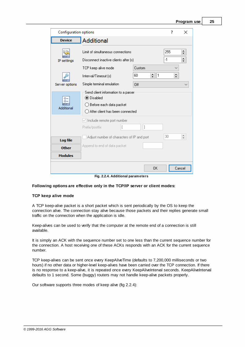
Additional parameters
The "Additional" tab contains additional settings of a TCP/IP or UDP connection (fig. 2.2.4).
Simple terminal emulation - the program realizes simple implementation of some terminalprotocols. If this emulation is enabled then the program will process some special commands andcharacter sequences.
Following options are effective only in the "TCP/IP server" mode:
Limit of simultaneous connections - you can define number of clients that can connect to theserver at the same time. It allows to optimize a server load with large number of TCP clients.Disconnect inactive clients after (s) - if a client is connected, but didn't send or receive any datawithin the specified time, then the connection with this client will be closed. If you will specify "-1"then the clients will not be disconnected.
25Program use
© 1999-2016 AGG Software
Fig. 2.2.4. Additional parameters
Following options are effective only in the TCP/IP server or client modes:
TCP keep alive mode
A TCP keep-alive packet is a short packet which is sent periodically by the OS to keep theconnection alive. The connection stay alive because those packets and their replies generate smalltraffic on the connection when the application is idle.
Keep-alives can be used to verify that the computer at the remote end of a connection is stillavailable.
It is simply an ACK with the sequence number set to one less than the current sequence number forthe connection. A host receiving one of these ACKs responds with an ACK for the current sequencenumber.
TCP keep-alives can be sent once every KeepAliveTime (defaults to 7,200,000 milliseconds or twohours) if no other data or higher-level keep-alives have been carried over the TCP connection. If thereis no response to a keep-alive, it is repeated once every KeepAliveInterval seconds. KeepAliveIntervaldefaults to 1 second. Some (buggy) routers may not handle keep-alive packets properly.
Our software supports three modes of keep alive (fig 2.2.4):

26 Advanced NMEA Data Logger
© 1999-2016 AGG Software
1. Off - the program doesn't use keep alive at all. You can disable keep alive if your network is verystable or your routers doesn't support it.
2. System - the program will use keep alive, but use system values of KeepAliveTime andKeepAliveInterval. These values are stored in the following registry branch:
[HKEY_LOCAL_MACHINE\System\CurrentControlSet\Services\Tcpip\Parameters]KeepAliveTime (32-bit number) = millisecondsKeepAliveInterval (32-bit number) = milliseconds
3. Custom - the program will use keep alive, but you can specify your values of KeepAliveTime andKeepAliveInterval, that are more applicable for your network and system. Note: in our software youshould define these values in seconds.
Note: Some routers may not allow keep-alive TCP packets. In this case the "keep-alive" function willnot work.
Following options are effective only in the server mode (TCP/IP or UDP):
Send client information to the a parser - if this option is activated then program will append asystem header to a data packet about the remote client. It allows the parser to separate datapackets from several clients that send data simultaneously.
4.6.3 Additional parameters4.6.3.1 Data view change
The data in the main window (fig.1.1.1 ) can be displayed in two modes (fig. 3.1.1):
1. The data can be displayed before processing. Before processing the data I fully complywith that has been read.
2. The data can be displayed after processing. After processing the data can be modifieddepending on the parser.
7
27Program use
© 1999-2016 AGG Software
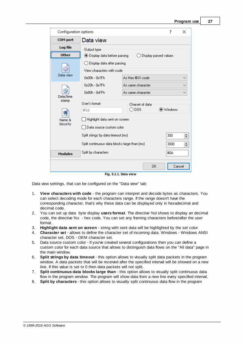
Fig. 3.1.1. Data view
Data view settings, that can be configured on the "Data view" tab:
1. View characters with code - the program can interpret and decode bytes as characters. Youcan select decoding mode for each characters range. If the range doesn't have thecorresponding character, that's why these data can be displayed only in hexadecimal anddecimal code.
2. You can set up data byte display users format. The directive %d shows to display an decimalcode, the directive %x - hex code. You can set any framing characters before/after the userformat.
3. Highlight data sent on screen - string with sent data will be highlighted by the set color.4. Character set - allows to define the character set of incoming data. Windows - Windows ANSI
character set, DOS - OEM character set.5. Data source custom color - if you've created several configurations then you can define a
custom color for each data source that allows to distinguish data flows on the "All data" page inthe main window.
6. Split strings by data timeout - this option allows to visually split data packets in the programwindow. A data packets that will be received after the specified interval will be showed on a newline. If this value is set to 0 then data packets will not split.
7. Split continuous data blocks large than - this option allows to visually split continuous dataflow in the program window. The program will show data from a new line every specified interval.
8. Split by characters - this option allows to visually split continuous data flow in the program

28 Advanced NMEA Data Logger
© 1999-2016 AGG Software
window using the specified symbols. For example (fig. 3.1.1), the program will use a characterwith the 0Ah hexadecimal code that is equal to the "LF" ASCII code.
4.6.3.2 Date/time configuration
This group of options (fig. 3.2.1) allows you to configure how data and time stamps appear in the logfile and on the screen. You can configure the stamp format in the program options .
Fig. 3.2.1 Time stamp configuration
Add to display output for data sent - the time stamp will be added for the sent data displayed onthe screen. The stamp will be added according to the timeout (if the data flow is uninterrupted) orwhen a data packet is sent.
Add to display output for data received - the same but for the received data.
Add if data direction has been changed - if the program is sending and receiving data, the timestamp will be also added when the data transfer direction changes (sending/receiving).
Add for data packets - if the data is displayed after it is processed, the stamp will be added toeach processed data packet.
56
29Program use
© 1999-2016 AGG Software
Add at begin of file - the stamp will be added at the beginning of every new log file.
Stamp timeout - if the data flow is uninterrupted, the stamp will be added regularly at the intervalspecified in milliseconds.
File prefix/postfix character(s) - the program will use these characters instead of those specifiedin the program options while writing data to a file. For example, it allows you to add the new linecharacter or another sequence of characters before or after the stamp. Example: >#0D#0A
4.6.3.3 Name and security
This group of options (fig. 3.3.1) allows you to configure the following parameters:
Friendly name - this name will be added before the port number or the data source in the drop-down list in the main window of the program. It allows you to describe the data source.
Start logging automatically - if this option is enabled, the program will start receiving and loggingdata automatically when it is launched.
The "Security" option group allows you to protect user operations in this particular configuration witha password. You can specify advanced security options applied to the entire program in the programoptions .
Ask password before start and stop - the password will be required when the user clicks the"Start/Pause" button in the main window of the program.
Ask password before configuration edit - the password will be required when the user tries toopen the Configuration options dialog box.
56
63

30 Advanced NMEA Data Logger
© 1999-2016 AGG Software
Fig. 3.3.1. Name and security

31Program use
© 1999-2016 AGG Software
4.6.4 Log files4.6.4.1 Log rotation
The main function of Advanced NMEA Data Logger is logging data to a file (so-called, log file). The"Log rotation" tab has a rich set of options for it. (fig. 4.1.1).
Fig. 4.1.1 Log-file forming modes
First of all, select log file what you can configure:
Log file for data received - all data received will be saved here.Log file for data sent - all data sent will be saved here. If you want to save data to the samefile, as data received, then select the "Log file rotation for data sent" from the list and enable twooptions: "Create log files on disk" and "Write to log for data received". Yes, of course, youshould configure a log rotation for data received before.
Set the "Create log file on disk" option to checked state. Then you can set path to folder, where fileswill be created with the help of dialog window, which will be showed up after clicking a button withpicture of opening folder. You should select a necessary folder in the dialog window and click the"OK" button.
Note: The program can work with network paths too, but in this mode, the program will increase

32 Advanced NMEA Data Logger
© 1999-2016 AGG Software
data flow over a network and can be failed with exceptional errors.
A log file name can be stamped with date and time. In this case a new log file is createdperiodically. The time stamp format depends on the selected period. For instance, if the "File nameprefix" field is set to "sample", the "File extension" field to "log" and the "File name format"option is "Daily", then each log file created will have the format "sampleYYYYMMDD.log". On March21st, 2003, the log file will be "sample20030321.log". Please, note, that the final extension (after thefinal period), remains at the end of the file name.
Log rotation mode is defined by the following key parameters:
File name prefix - text string, which will be added at file name beginning;File name extension - text string, which will be a file extension (characters after dot);
Limit size - the "Limit size" field specify the maximum size in kilobytes of any log file. If you'llspecify zero size, then the file size will not limited. You may select from the following modes:1. Clear file - if the log file size will exceed the limit specified, then the log file content will be
deleted and file filling will start from beginning.2. Rename old - if the log file size will exceed the limit specified then the existing log file will be
renamed.3. Shift (no threshold) - the older data over the limit specified will removed from the log file.4. Shift (with threshold). In this mode the program will wait when the file size will exceed the limit
specified + the threshold value. After this, the older data over the limit specified will removed fromthe log file.
If the program works continuous for a long time, it is possible that the log file will have large size andthis file will be inconvenient for looking and analysing. For this there is the possibility to create filesin dependence with the time on PC. You can select one variant predefined or set up new one:
Daily - file will be created with name containing prefix, and date in format DDMMYYYY, whereDD is two-digit day sign, MM is two-digit month sign and YYYY is four digits of the current year.The file name extension will be added at the end of file;Monthly - file will be created with name containing prefix, and date in MMYYYY format. The filename extension will be added at the end of file;Each data packet in different file - in this mode the program splits data flow to a different file.In this mode you should configure the parser or the program will split a data by timeout about300 ms.Don't create new file - in this mode the program will write all data to one file. It isrecommended for a small data flow. Otherwise your log file will be too big and a performance ofthe program will fall down;User's format - file will be created with name containing prefix and date in showed by youformat (for example, DDMMYYYY). The file name extension will be added at the end of file. Thefile may not contain format signs, then file name will be constant. You should not usecharacters, that the OS doesn't allows in file name, such as "/,\.*,?" and some others;Weekly - create a new file every week. The file name will contains a week number;After data timeout - the program will create a new file if the program didn't receive any data atthe specified interval.Hourly - file will be created with name containing prefix, and date in format YYYYMMDDHH,where HH is two-digit hour sign, DD is two-digit day sign, MM is two-digit month sign and YYYYis four digits of the current year. The file name extension will be added at the end of file;Constantly named file - the current log file will have a constant name. When creating a newfile the existing log file will be saved using the new file name that will contain a data and time

33Program use
© 1999-2016 AGG Software
stamp.
Date and time formatting codes:
d - day, not adding null(1-31).dd - day ,adding null(01-31).ddd - day of the week in text form(Mon-Sat) according to standard, set on this computer.dddd - day of the week in full text form(Monday-Saturday) according to standard, set on thiscomputer.m - month, not adding null(1-12).mm - month, adding null (01-12).mmm - month in text form(Jan-Dec) according to standard, set on this computer.mmmm - month in full text form (January- December) according to standard, set on this computer.yy - year in the form of two last digits(00-99)yyyy - year in the form of four last digits (0000-9999).h - hours, not adding null (0-23).hh - hours, adding null (00-23).n - minutes, not adding null (0-59)nn - minutes, adding null (00-59).s - seconds, not adding null (0-59).ss - seconds, adding null (00-59).
Example: you want to create log file every hour. It is desired that file name starts from "sample_log"and the file extension "txt".
Answer: set file prefix = sample_log_, file extension= txt (without dot!). In file name format showHHDDMMYYYY. Now file will be created every hour. Naturally, you can set any formattingcharacters combination, described higher.
If you want to access to a log file while the program work, then you should configure access modesettings for the log file in the next chapter.
Add date/time stamp to file name - this option is available for modes #4 and #7 and allows to adddate and time to the file name.
Add data source ID to file name - if this options is activated then then the program will append thedata source name at the beginning of the file name. For example, COM1-sample20030321.log.
Write data/time stamp to file before writing data - if this options is activated then then theprogram will write a date/time stamp to a file before each data portion.
Overwrite existing files - this option is available for modes #4 and #7 and allows to delete anexisting log file before creating a new log file.
4.6.4.2 Log file access
During work can be such situations, when it is necessary to get access to a file with current data(current log file) from other applications (for example, for data processing). But while you areaccessing the current log file Advanced NMEA Data Logger can't write data to a log file and all dataat this moment will be lost. We recommend to use a temporary file for data storage. It is most safeway. (fig. 4.2.1).
33

34 Advanced NMEA Data Logger
© 1999-2016 AGG Software
Fig. 4.2.1 File access mode.
You can select one from following variants:
Ignore and not write - with this mode, the data will be lost;Write to a temporary file, then append - a temporary file will be created, to which writing willbe done. After access to current file will be got, temporary file content will be added to the endof main file. But mind that if file is created in dependence of time, there can be a situation whenat temporary file forming name of the main file will be changed. Then temporary file will be addedto the end of newly created file.Display a message and stop work - data will be lost until dialog window is closed.
You can set up your message text, which will be displayed at writing error to data file. The soundsignal can be on for an additional indication. You can also enable writing a message to a protocolfile.
4.6.4.3 Log deletion
The deletion of files (fig. 4.3.1) will help you to avoid stuffing your hard disk with needlessinformation. Log files can be deleted either depending on the time of storing or when the maximalnumber of files is exceeded.

35Program use
© 1999-2016 AGG Software
When deleting files by the time of their storage, the files that were modified last time before thespecified period are deleted.
When controlling the number of files, the files with the oldest modification dates are deleted first.
You can select both variants of file deletion. In that case files will be deleted when either of theconditions is true.
Fig. 4.3.1 Log deletion
4.6.5 Modules4.6.5.1 Introduction & setup
To extend program functionality we implemented plug-ins modules. Module structure lets reduceyour program size and purchase costs (you pay only functionality, which you need), to low downprogram distributive download time, your computer processor load and reduce disk space.
Advanced NMEA Data Logger supports few types of modules (fig. 5.1.1 - 5.1.3):
Data query - transmits queries or commands out the data source to control or query your
instruments directly;

36 Advanced NMEA Data Logger
© 1999-2016 AGG Software
Data parser - data parser that allows you to parse, filter and format more complex data from
more sophisticated devices. Some of the advanced features of the parser are the ability towork with raw binary or hex data;
Data filter - data filters allow you to filter your data and modify values of parser variables;
Data export (fig.11) - Advanced NMEA Data Logger has many modules for passing serial
data directly to other applications, such as as keystrokes where incoming data is passed toother programs as a sequence of keys, as DDE Server that passes data to other programsusing Dynamic Data Exchange, ODBC for exporting data to a database and many others;
Events handling (fig.12) - an external plug-ins used to handle events generated by the
Advanced NMEA Data Logger software. Once an event occurs (for example: "Data source isopened" or "Configuration changed"), the plug-in creates a text message using the specifiedtemplate and sends a notification, do some actions, such as execute programs, scripts andetc. The form of the notification or actions depends on the plug-in settings.
Fig. 5.1.1. Activating plug-ins

37Program use
© 1999-2016 AGG Software
Fig. 5.1.2 Activating data export plug-ins

38 Advanced NMEA Data Logger
© 1999-2016 AGG Software
Fig. 5.1.3 Activating events handling plug-ins
You can parse and export data sent and received (fig. 5.1.1). By default, only data received will beparsed.
Installation
You can easily install a new module. usually, you should start the installation file and click the"Next" button for few times. The installation wizard will detect a place of your Advanced NMEA DataLogger software and place a plug-in module and all distributive files to the "Plugins" folder, which isin the program folder (by default X:\\Program Files\Advanced NMEA Data Logger\Plugins).
After program restart a module will be loaded and initialized. If module is supported with oursoftware, its short description you will see in modules list (Fig. 5.1.1-5.1.3). Most modules requireadditional settings. If you want to configure the plug-in module, simply click the "Setup" button nearit. If you selected the module and the "Setup" button is not active, then module doesn't haveadditional settings and can work without additional settings. Please, read users manual of acorresponding plug-in for additional information.
Configuration steps
1. Select and configure a query module. You may use a module of this type if you need to send

39Program use
© 1999-2016 AGG Software
some data to your device (for example, initialization strings or request strings).2. Select and configure a parser module. This step is necessary, because filter and export modules
can use parsed data only. If you didn't select the parser module, then you can't configure the datafilter and data export modules.
3. Activate and configure data export modules. You can select one or more modules simultaneously.The program will use selected modules simultaneously. Please, note, the program can' use thedata export module, if you didn't configure the parser module.
4. Activate and configure event modules. You can select one or more modules simultaneously.
4.6.5.2 OPC server
Since the version 2.1.1 Advanced NMEA Data Logger has an internal OPC server. It means, that anyOPC compatible client application can get data from Advanced NMEA Data Logger without anyadditional software. For connecting to the OPC server our OPC server has an unique attributes (Fig.5.2.1). Before using the OPC server on your PC you should download and install the OPC CoreComponents Redistributable from www.opcfoundation.org (registration required).
Fig. 5.2.1 OPC server parameters
Advanced NMEA Data Logger are parsing all incoming data to one or more variables and OPC clientare getting it (fig. 5.2.2). After connecting to the OPC server you will get list of all variables.

40 Advanced NMEA Data Logger
© 1999-2016 AGG Software
Fig. 5.2.2 OPC server active items
Clients activity is showed on the "Active clients" tab. The top node is client, below is group of itemsand connected items. By double-clicking, you can get a detailed information about each node.

41Program use
© 1999-2016 AGG Software
Fig. 5.2.3 OPC server clients
Advanced NMEA Data Logger creates new variables at "on-the-fly" mode. The Advanced NMEA DataLogger starts without any variables and get it only after first data had been received. If your clientOPC will connect to the OPC server before, than data had been processed, then it will get empty listof variables and your OPC client should poll the OPC server for updating list of variables. If your OPCclient doesn't allow it, then your can pre-define all variables (fig.5.2.4). In this case the OPC serverwill create these variables with empty values, immediate after starting and your OPC client will getthese names while connecting.
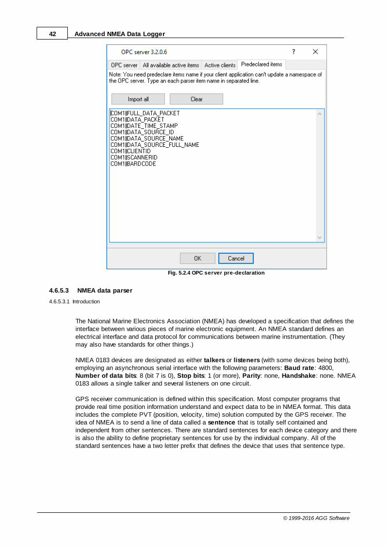
42 Advanced NMEA Data Logger
© 1999-2016 AGG Software
Fig. 5.2.4 OPC server pre-declaration
4.6.5.3 NMEA data parser
4.6.5.3.1 Introduction
The National Marine Electronics Association (NMEA) has developed a specification that defines theinterface between various pieces of marine electronic equipment. An NMEA standard defines anelectrical interface and data protocol for communications between marine instrumentation. (Theymay also have standards for other things.)
NMEA 0183 devices are designated as either talkers or listeners (with some devices being both),employing an asynchronous serial interface with the following parameters: Baud rate: 4800,Number of data bits: 8 (bit 7 is 0), Stop bits: 1 (or more), Parity: none, Handshake: none. NMEA0183 allows a single talker and several listeners on one circuit.
GPS receiver communication is defined within this specification. Most computer programs thatprovide real time position information understand and expect data to be in NMEA format. This dataincludes the complete PVT (position, velocity, time) solution computed by the GPS receiver. Theidea of NMEA is to send a line of data called a sentence that is totally self contained andindependent from other sentences. There are standard sentences for each device category and thereis also the ability to define proprietary sentences for use by the individual company. All of thestandard sentences have a two letter prefix that defines the device that uses that sentence type.
43Program use
© 1999-2016 AGG Software
(For GPS receivers the prefix is GP.) which is followed by a three letter sequence that defines thesentence contents. In addition NMEA permits hardware manufactures to define their own proprietarysentences for whatever purpose they see fit. All proprietary sentences begin with the letter P and arefollowed with 3 letters that identifies the manufacturer controlling that sentence. For example aGarmin sentence would start with PGRM and Magellan would begin with PMGN.
Our module parse each sentence begins with a '$' and ends with CRLF (a carriage return/line feedsequence). The data is contained within this single line with data items separated by commas. Thedata itself is just ASCII text and may extend over multiple sentences in certain specializedinstances but is normally fully contained in one variable length sentence. The data may vary in theamount of precision contained in the message. For example time might be indicated to decimalparts of a second or location may be show with 3 or even 4 digits after the decimal point. There is aprovision for a checksum at the end of each sentence which may or may not be checked by the unitthat reads the data. The checksum field consists of a '*' and two hex digits.
Our parser module splits all data to variables and this variables can be used in data export modules.
4.6.5.3.2 Common parameters
These parameters are used for data parsing (fig. 5.3.1).
1. Add date/time stamp to each sentence parsed - the parser will add an additional stampvalue to other values, that the parser will extract from a data block;
2. Add serial port number to each sentence parsed - the parser will add an additional valuewith serial port number, that received this data block. You can use it in a multi portconfiguration, for identifying sentences from different serial ports.
3. Verify sentence checksum if available - the parser will calculate a checksum and verify itfor each sentence that will contain '*' characters at the end of sentence:
Sentence example: GPGGA,123519,4807.038,N,01131.000,E,1,08,0.9,545.4,M,46.9,M,,*47

44 Advanced NMEA Data Logger
© 1999-2016 AGG Software
Fig. 5.3.1 Common parameters
Aggregate sentences
This option is very useful if your talker sends more than one sentence and you want to save data toa file at single row. You can aggregate two or more sentences and data of these sentences will besend to data export modules at same moment with one date time stamp. If you'll specify sentencenames then the module will store all data in a temporary buffer, while all sentences isn't received.When all data is received the module sends data to a data export module, clears the buffer andstarts waiting for new data.
You can specify one or more different aggregate groups. Simply add sentence name to differentrows. Sentences in the row should be separated by comma and a sentence should contain a talkername.
4.6.5.3.3 NMEA sentences parser
If you want to export to any target, then you should configure a parser module. The ASCII dataparser allows you to extract data from data flow, that contains a ASCII characters. The parsermodule splits data flow to data block and extracts data values from each data block. On the"sentence" tab (fig. 5.3.2) you should specify sentences, that the parser will parse. Other sentenceswill be ignored.

45Program use
© 1999-2016 AGG Software
Fig. 5.3.2 NMEA sentences
The full list of supported sentences and variables that parsed from each sentence is listed here .
Our software create variables with following types:String - Characters array with length from 1 to 65535 characters;Boolean - Logical value (True/False) - 0 or 1;Float - Real number - value range: -2.9 x 10 -̂39 .. 1.7 x 10 3̂8Integer - Integer value: -2147483648..2147483647;DateTime - Date and time.
Note: Our modules doesn't support Time and Date data types. Therefore time variables, that existsin a sentence contains current date, but with time from the sentence.
4.6.5.3.4 Supported talkers
AG - Autopilot - GeneralAP - Autopilot - MagneticCD - Communications – Digital Selective Calling (DSC)CR - Communications – Receiver / Beacon ReceiverCS - Communications – SatelliteCT - Communications – Radio-Telephone (MF/HF)CV - Communications – Radio-Telephone (VHF)CX - Communications – Scanning ReceiverDF - Direction Finder
46

46 Advanced NMEA Data Logger
© 1999-2016 AGG Software
EC - Electronic Chart Display & Information System (ECDIS)EP - Emergency Position Indicating Beacon (EPIRB)ER - Engine Room Monitoring SystemsGP - Global Positioning System (GPS)HC - Heading – Magnetic CompassHE - Heading – North Seeking GyroHN - Heading – Non North Seeking GyroII - Integrated InstrumentationIN - Integrated NavigationLC - Loran CP - Proprietary CodeRA - RADAR and/or ARPASD - Sounder, DepthSN - Electronic Positioning System, other/generalSS - Sounder, ScanningTI - Turn Rate IndicatorVD - Velocity Sensor, Doppler, other/generalDM - Velocity Sensor, Speed Log, Water, MagneticVW - Velocity Sensor, Speed Log, Water, MechanicalWI - Weather InstrumentsYX - TransducerZA - Timekeeper – Atomic ClockZC - Timekeeper – ChronometerZQ - Timekeeper – QuartzZV - Timekeeper – Radio Update, WWV or WWVH
4.6.5.3.5 Supported sentences
AAM - Waypoint arrival alarmAAM_ARIV_ENT - Arrival circle enteredAAM_PERP_PASS - Perpendicular passedAAM_CIRCLE_RAD - Circle radiusAAM_CIRCLE_RAD_UNIT - Circle radius unitsAAM_WPTNAME - Waypoint name
ALM - GPS Almanac dataALM_SENT_NUM - Number of sentencesALM_SENT_CNT - Sentence countALM_PRN_ID - Satellite PRN numberALM_WEEK_NO - GPS week numberALM_SV_HEALTH - SV healthALM_ECCENTRICITY - EccentricityALM_REF_TIME - Almanac reference timeALM_INC_ANGLE - Inclination angleALM_RA_RATE - Rate of right ascensionALM_AXIS_ROOT - Root of semi-major axisALM_PEREGREE_ARG - Argument of perigeeALM_NODE_LONG - Longitude of ascension nodeALM_MEAN_ANN - Mean anomalyALM_F0_CLOCK - F0 clock parameterALM_F1_CLOCK - F1 clock parameter
APA - Auto pilot A sentenceAPA_STATUS1 - Loran-C blink/SNR warning, general warning

47Program use
© 1999-2016 AGG Software
APA_STATUS2 - Loran-C cycle warningAPA_CROSS_TRACK_RAD - Cross-track error distanceAPA_STEER - Steer to correctAPA_CROSS_TRACK_RAD_UNIT - Cross-track error unitsAPA_ARIV_ALRM_C - Arrival alarm - circleAPA_ARIV_ALRM_P - Arrival alarm - perpendicularAPA_MAG_BEAR_OD - Magnetic bearing, origin to destinationAPA_MAG_BEAR_OD_UNIT - Magnetic bearing unitAPA_DEST_WPTID - Destination waypoint ID
APB - Auto pilot B sentenceAPB_STATUS1 - Loran-C blink/SNR warning, general warningAPB_STATUS2 - Loran-C cycle warningAPB_CROSS_TRACK_RAD - Cross-track error distanceAPB_STEER - Steer to correctAPB_CROSS_TRACK_RAD_UNIT - Cross-track error unitsAPB_ARIV_ALRM_C - Arrival alarm - circleAPB_ARIV_ALRM_P - Arrival alarm - perpendicularAPB_MAG_BEAR_OD - Magnetic bearing, origin to destinationAPB_MAG_BEAR_OD_UNIT - Magnetic bearing unitAPB_DEST_WPTID - Destination waypoint IDAPB_MAG_BEAR_PD - Magnetic bearing, present position to destination APB_MAG_BEAR_PD_UNIT - Magnetic bearing unitAPB_MAG_BEAR_HS - Magnetic heading to steerAPB_MAG_BEAR_HS_UNIT - Magnetic heading unit
BEC - Bearing and distance to waypoint – dead reckoningBEC_UTC - UTC time of fixBEC_WPT_LAT - Latitude of waypointBEC_WPT_LAT_H - Latitude hemisphereBEC_WPT_LONG - Longitude of waypointBEC_WPT_LONG_H - Longitude hemisphereBEC_BEARING - Bearing to waypointBEC_BEAR_TYPE - Bearing to waypoint typeBEC_DIST - Distance to waypointBEC_DIST_UNIT - Distance to waypoint unitsBEC_WPTID - Waypoint ID
BOD - Bearing origin to destinationBOD_BEARING - Bearing from START to DEST, degreesBOD_BEAR_TYPE - Bearing from START to DEST typeBOD_DEST_WPTID - Destination waypoint IDBOD_ORIG_WPTID - Origin waypoint ID
BWC - Bearing using great circle routeBWC_DEPTH - DepthBWC_DEPTH_UNIT - Depth unit
DBS - Depth below surfaceDBS_DEPTH - Depth, metersDBS_OFFSET - Offset from transducer
FSI - Frequency set informationFSI_TX_FREQ - Transmitting frequencyFSI_RX_FREQ - Receiving frequencyFSI_COMM_MODE - Communications modeFSI_POWER_LEVEL - Power Level
GGA - GPS fix data

48 Advanced NMEA Data Logger
© 1999-2016 AGG Software
GGA_TAKEN_AT - Fix taken atGGA_LATITUDE_DEG - LatitudeGGA_LATITUDE_DEG_H - Latitude hemisphereGGA_LONGITUDE_DEG - LongitudeGGA_LONGITUDE_DEG_H - Longitude hemisphereGGA_QUALITY - Fix qualityGGA_SAT_NUM - Number of satellites being trackedGGA_HOR_DIL - Horizontal dilution of positionGGA_ALTITUDE - Altitude above mean sea levelGGA_ALTITUDE_UNIT - Altitude unitsGGA_HEIGHT_OF_GEOID - Height of geoid (mean sea level) above WGS84 ellipsoidGGA_HEIGHT_OF_GEOID_UNIT - Height of geoid unitsGGA_TIME_SNC_DGPS - Time in seconds since last DGPS updateGGA_DGPS_ID - DGPS station ID number
GLC - Geographic position, Loran-CGLC_GRI_MS - GRI MicrosecondsGLC_TOA_MS - Master TOA microsecondsGLC_TOA_STATUS - Master TOA signal statusGLC_TIME_DIFF_MS - Time difference in microsecondsGLC_TIME_DIFF_STATUS - Time difference signal status
GLL - Geographic position, lat/lon dataGLL_LATITUDE_DEG - LatitudeGLL_LATITUDE_DEG_H - Latitude hemisphereGLL_LONGITUDE_DEG - LongitudeGLL_LONGITUDE_DEG_H - Longitude hemisphereGLL_TAKEN_AT - Fix taken atGLL_STATUS - Status
GSA - Overall satellite dataGSA_AUTO_SEL - Auto selection of 2D or 3D fixGSA_3D_FIX - 3D fixGSA_SAT_PRN - Sat used for fixGSA_PDOP - Dilution of precisionGSA_HDOP - Horizontal dilution of precisionGSA_VDOP - Vertical dilution of precision
GSV - Detailed satellite dataGSV_SENT_NUM - Number of sentencesGSV_SENT_CNT - Sentence countGSV_SAT_IN_VIEW - Number of satellites in viewGSV_SAT_PRN - Satellite PRN numberGSV_ELEVATION - Elevation, degreesGSV_AZIMUTH - Azimuth, degreesGSV_SNR - SNR - higher is better
GTD - Geographic location in time differencesGTD_TIME_DIFF - Time difference
HDG - Heading, deviation and variationHDG_MAG_HEAD - Magnetic sensor heading in degreesHDG_MAG_DEV - Magnetic deviation in degreesHDG_MAG_DEV_DIR - Magnetic deviation directionHDG_MAG_VAR - Magnetic variation in degreesHDG_MAG_VAR_DIR - Magnetic variation direction
HDM - Heading, magneticHDM_HEADING - Heading in degrees

49Program use
© 1999-2016 AGG Software
HDM_HEADING_UNIT - Heading unitHDT - Heading, true
HDT_HEADING - Heading in degreesHDT_HEADING_UNIT - Heading unit
LCD - Loran-C signal dataLCD_GRI_MS - GRI MicrosecondsLCD_MR_SNR - Master relative SNRLCD_MR_ECD - Master relative ECDLCD_TIME_DIFF_MS - Time difference in microsecondsLCD_TIME_DIFF_STATUS - Time difference signal status
MSK - Send control for a beacon receiverMSK_FREQ - FrequencyMSK_FREQ_MODE - Frequency modeMSK_BITRATE - BitrateMSK_BITRATE_MODE - Bitrate modeMSK_FREQ_STATUS - Frequency for MSS message status
MSS - Beacon receiver status informationMSS_SIGNAL_S - Signal strength in dBMSS_SIGNAL_N - Signal to noise ratio in dBMSS_BEACON_FREQ - Beacon frequency in KHzMSS_BEACON_BITRATE - Beacon bitrate in bps
MTW - Water temperatureMTW_DEGREES - DegreesMTW_DEGREES_UNIT - Unit of measurement
MWV - Wind speed and angleMWV_ANGLE - Wind angleMWV_REF - ReferenceMWV_SPEED - Wind speedMWV_SPEED_UNIT - Wind speed unitMWV_STATUS - Status
OSD - Own ship dataOSD_HEADING - Heading true, degreesOSD_STATUS - StatusOSD_VESSEL - Vessel сourse true, degreesOSD_VESSEL_REF - Course referenceOSD_VESSEL_SPEED - Vessel speedOSD_SPEED_REF - Speed referenceOSD_VESSEL_SET - Vessel set true, degreesOSD_VESSEL_DRIFT - Vessel drift true, degreesOSD_VESSEL_DRIFT_UNIT - Vessel drift unit
ROO - Waypoints in active routeROO_WPT_ID - Waypoint identifier
RMA - Recommended minimum navigation informationRMA_STATUS - StatusRMA_LATITUDE_DEG - LatitudeRMA_LATITUDE_DEG_H - Latitude hemisphereRMA_LONGITUDE_DEG - LongitudeRMA_LONGITUDE_DEG_H - Longitude hemisphereRMA_TIME_DIFF_A - Time difference ARMA_TIME_DIFF_B - Time difference BRMA_SPEED - Speed over the ground in knotsRMA_TRACK_ANGLE - Track angle in degrees

50 Advanced NMEA Data Logger
© 1999-2016 AGG Software
RMA_MAGN_VAR - Magnetic variationRMA_MAGN_VAR_H - Magnetic variation hemisphere
RMB - Recommended minimum navigation informationRMB_STATUS - StatusRMB_CROSS_TRACK_ERR - Cross-track errorRMB_CROSS_TRACK_ERR_DIR - Cross-track error steerRMB_ORIG_WPTID - Origin waypoint IDRMB_DEST_WPTID - Destination waypoint IDRMB_WPT_LAT - Latitude of destination waypointRMB_WPT_LAT_H - Latitude hemisphereRMB_WPT_LONG - Longitude of destination waypointRMB_WPT_LONG_H - Longitude hemisphereRMB_RANGE - Range to destination, nautical milesRMB_BEAR - True bearing to destinationRMB_BEAR - Velocity towards destination, knotsRMB_ARIV_ALRM - Arrival alarm
RMC - Recommended minimum navigation informationRMC_TAKEN_AT - Fix taken atRMC_STATUS - StatusRMC_LATITUDE_DEG - LatitudeRMC_LATITUDE_DEG_H - Latitude hemisphereRMC_LONGITUDE_DEG - LongitudeRMC_LONGITUDE_DEG_H - Longitude hemisphereRMC_SPEED - Speed over the ground in knotsRMC_TRACK_ANGLE - Track angle in degreesRMC_DATE - DateRMC_MAGN_VAR - Magnetic variationRMC_MAGN_VAR_H - Magnetic variation hemisphere
ROT - Rate of turnROT_RATE_OF_TURN - Rate of turn, degrees per minuteROT_STATUS - Status
RPM - RevolutionsRPM_SOURCE - SourceRPM_NUM - Engine or shaft numberRPM_SPEED - Speed, revolutions per minuteRPM_PITCH - Propeller pitch, % of maximumRPM_STATUS - Status
RSA - Rudder sensor angleRSA_SR_SENSOR - Starboard (or single) rudder sensorRSA_STATUS - Starboard rudder sensor statusRSA_PR_SENSOR - Port rudder sensorRSA_STATUS - Port rudder sensor status
RSD - Radar system dataRSD_CURSOR_RANGE - Cursor range from own shipRSD_CURSOR_BEARING - Cursor bearing CW from zero, degreesRSD_RANGE_SCALE - Range scaleRSD_RANGE_UNIT - Range units
RTE - Route messageRTE_SENT_NUM - Number of sentencesRTE_SENT_CNT - Sentence countRTE_TYPE - TypeRTE_TYPE_NAME - Type name

51Program use
© 1999-2016 AGG Software
RTE_ID - Route identifierRTE_WPT_ID - Waypoint identifier
SFI - Scanning frequency informationSFI_SENT_NUM - Number of sentencesSFI_SENT_CNT - Sentence countSFI_FREQ - FrequencySFI_MODE - Mode
STN - Multiple data IDSTN_ID - Talker ID number
TTM - Tracked target messageTTM_TARGET_NUM - Target numberTTM_TARGET_DIST - Target distanceTTM_BEARING - Bearing from own shipTTM_BEAR_TYPE - Bearing unitsTTM_TARGET_SPEED - Target speedTTM_TARGET_COURSE - Target courseTTM_COURSE_UNIT - Course unitsTTM_DIST_CPA - Distance of closest-point-of-approachTTM_TIME_CPA - Time until closest-point-of-approach '-' means increasingTTM_SIGN - '-' means increasingTTM_TARGET_NAME - Target nameTTM_TARGET_STATUS - Target statusTTM_REF_TARGET - Reference target
VBW - Dual ground/water speedVBW_WATER_LONG_SPEED - Longitudinal water speedVBW_WATER_TRAV_SPEED - Transverse water speedVBW_WATER_STATUS - Water speed statusVBW_GROUND_LONG_SPEED - Longitudinal ground speedVBW_GROUND_TRAV_SPEED - Transverse ground speedVBW_GROUND_STATUS - Ground speed status
VDR - Set and driftVDR_DEGRESS - DegressVDR_DEGRESS_TYPE - Degress typeVDR_SPEED - SpeedVDR_SPEED_UNIT - Speed units
VHW - Water speed and headingVHW_DEGRESS - DegressVHW_DEGRESS_TYPE - Degress typeVHW_SPEED - SpeedVHW_SPEED_UNIT - Speed units
VLW - Distance traveled through waterVLW_TOTAL - Total cumulative distanceVLW_TOTAL_UNIT - Total cumulative distance unitVLW_RESET - Distance since ResetVLW_RESET_UNIT - Distance since Reset unit
VPW - Speed, measured parallel to windVPW_SPEED - SpeedVPW_SPEED_UNIT - Speed units
VTG - Vector track an speed over the groundVTG_MAG_TRACK - Track madeVTG_MAG_TRACK_TYPE - Track made typeVTG_SPEED - Ground speed

52 Advanced NMEA Data Logger
© 1999-2016 AGG Software
VTG_SPEED_UNIT - Ground speed unitsVWR - Relative wind speed and angle
VWR_WIND_DIR - Wind direction magnitude in degreesVWR_WIND_DIR_TYPE - Wind direction typeVWR_SPEED - SpeedVWR_SPEED_UNIT - Speed units
WCV - Waypoint closure velocityWCV_VELOCITY - VelocityWCV_VELOCITY_UNIT - Velocity unitsWCV_WPT_ID - Waypoint identifier
WNC - Distance, waypoint to waypointWNC_DISTANCE - DistanceWNC_DISTANCE_UNIT - Distance unitsWNC_DEST_WPTID - Destination waypoint IDWNC_ORIG_WPTID - Origin waypoint ID
WPL - Waypoint informationWPL_LATITUDE_DEG - LatitudeWPL_LATITUDE_DEG_H - Latitude hemisphereWPL_LONGITUDE_DEG - LongitudeWPL_LONGITUDE_DEG_H - Longitude hemisphereWPL_WPTNAME - Waypoint name
XDR - Multiple cross track error, dead reckoningXDR_TRANS_TYPE - Transducer typeXDR_MEASURE_DATA - Measurement dataXDR_MEASURE_UNIT - Measurement data unitsXDR_TRANS_NAME - Name of transducer
XTE - Measured cross track errorXTE_GEN_WARN - General warning flagXTE_LORAN_LOCK - Loran-C cycle lock flagXTE_CROSS_TRACK_DIST - Cross track error distanceXTE_STEER - SteerXTE_DIST_UNIT - Distance units
XTR - Cross track error, dead reckoningXTR_TRANS_TYPE - Transducer typeXTR_MEASURE_DATA - Measurement dataXTR_MEASURE_UNIT - Measurement data unitsXTR_TRANS_NAME - Name of transducer
ZDA - Date and TimeZDA_TIME - TimeZDA_DAY - DayZDA_MONTH - MonthZDA_YEAR - YearZDA_ZONE_HOUR - Local zone hoursZDA_ZONE_MIN - Local zone minutes
ZFO - UTC and time to destination waypointZFO_TIME - TimeZFO_TIME_REMAIN - Time remainingZFO_WPT_ID - Waypoint identifier
GRMC - Sensor configuration informationGRMC_MODE - Fix modeGRMC_ALT - Altitude above/below mean sea levelGRMC_DATUM_INDEX - Earth datum index

53Program use
© 1999-2016 AGG Software
GRMC_DATUM_AXIS - User earth datum semi-major axisGRMC_DATUM_FACTOR - User earth datum inverse flattening factorGRMC_DATUM_DELTA_X - User earth datum delta x earth centered coordinateGRMC_DATUM_DELTA_Y - User earth datum delta y earth centered coordinateGRMC_DATUM_DELTA_Z - User earth datum delta z earth centered coordinateGRMC_DIFF_MODE - Differential modeGRMC_BAUD_RATE - NMEA Baud rateGRMC_FILTER_MODE - Filter modeGRMC_PPS_MODE - PPS mode
GRME - Estimated position errorGRME_HPE - Estimated horizontal position error (HPE)GRME_HPE_UNIT - HPE unitsGRME_VPE - Estimated vertical error (VPE)GRME_VPE_UNIT - VPE unitsGRME_OSEPE - Overall spherical equivalent position error (OSEPE)GRME_OSEPE_UNIT - SEPE units
GRMF - Position fix sentenceGRMF_WEEK_NO - GPS week numberGRMF_SEC_NUM - GPS secondsGRMF_UTC_DATE - UTC date of position fixGRMF_UTC_TIME - UTC time of position fixGRMF_LEAP_SEC_NUM - GPS leap second countGRMF_LATITUDE_DEG - LatitudeGRMF_LATITUDE_DEG_H - Latitude hemisphereGRMF_LONGITUDE_DEG - LongitudeGRMF_LONGITUDE_DEG_H - Longitude hemisphereGRMF_MODE - ModeGRMF_FIX_TYPE - Fix typeGRMF_SPEED - Speed over ground, km/hGRMF_COURSE - Course over ground, degreesGRMF_DIL_POS - Position dilution of precisionGRMF_TIME_DIL_POS - Time dilution of precision
GRMI - Sensor initialization informationGRMI_LATITUDE_DEG - LatitudeGRMI_LATITUDE_DEG_H - Latitude hemisphereGRMI_LONGITUDE_DEG - LongitudeGRMI_LONGITUDE_DEG_H - Longitude hemisphereGRMI_UTC_DATE - Current UTC dateGRMI_UTC_TIME - Current UTC time
GRMM - Map datumGRMM_DATUM - Currently active horizontal datum
GRMO - Output sentence enable/disableGRMO_NAME - Target sentence descriptionGRMO_MODE - Target sentence mode
GRMV - 3D velocityGRMV_EAST_VEL - True east velocityGRMV_NORTH_VEL - True north velocityGRMV_UP_VEL - Up velocity
GRMZ - Altitude informationGRMZ_ALT - AltitudeGRMZ_ALT_UNIT - Altitude unitsGRMZ_POS_FIX_DIM - Position fix dimensions

54 Advanced NMEA Data Logger
© 1999-2016 AGG Software
SLIB - Differential GPS beacon receiver controlSLIB_FREQ - FrequencySLIB_BITRATE - Bit rateSLIB_REQ_TYPE - Request type
SRF150 - OK to sendSRF150_STATUS - Status
SRF161 - OK to sendSRF161_ANT_STATUS - Antenna statusSRF161_AGC - AGC
4.7 Program options
4.7.1 Window view
This tab in program options (fig. 6.1.1) allows you to customize appearance of the main window ofthe program (fig.1.1.1 ). You can access this tab through the "Options -> Program options" menuitem in the main window.
Fig. 6.1.1 Window view setting
You can set following parameters:
7
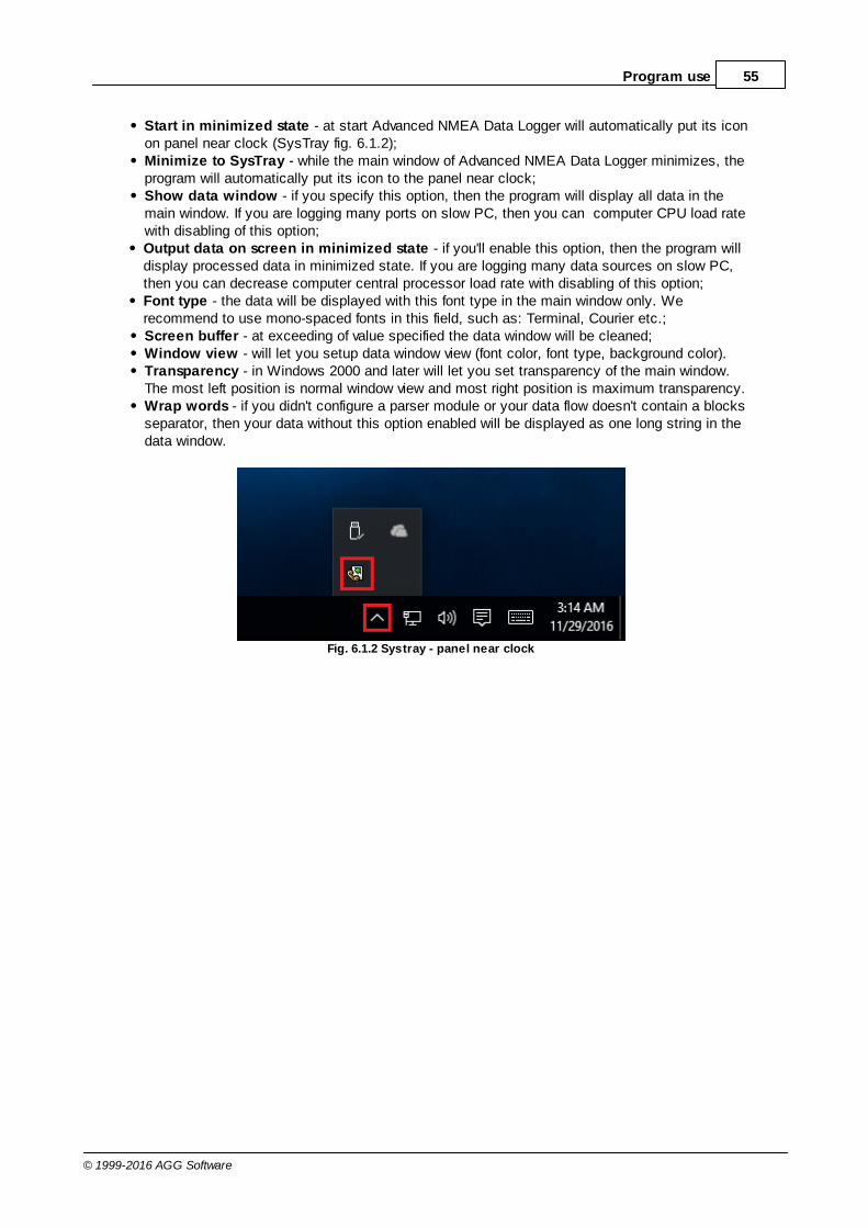
55Program use
© 1999-2016 AGG Software
Start in minimized state - at start Advanced NMEA Data Logger will automatically put its iconon panel near clock (SysTray fig. 6.1.2);Minimize to SysTray - while the main window of Advanced NMEA Data Logger minimizes, theprogram will automatically put its icon to the panel near clock;Show data window - if you specify this option, then the program will display all data in themain window. If you are logging many ports on slow PC, then you can computer CPU load ratewith disabling of this option;Output data on screen in minimized state - if you'll enable this option, then the program willdisplay processed data in minimized state. If you are logging many data sources on slow PC,then you can decrease computer central processor load rate with disabling of this option;Font type - the data will be displayed with this font type in the main window only. Werecommend to use mono-spaced fonts in this field, such as: Terminal, Courier etc.;Screen buffer - at exceeding of value specified the data window will be cleaned;Window view - will let you setup data window view (font color, font type, background color).Transparency - in Windows 2000 and later will let you set transparency of the main window.The most left position is normal window view and most right position is maximum transparency.Wrap words - if you didn't configure a parser module or your data flow doesn't contain a blocksseparator, then your data without this option enabled will be displayed as one long string in thedata window.
Fig. 6.1.2 Systray - panel near clock

56 Advanced NMEA Data Logger
© 1999-2016 AGG Software
4.7.2 Date/time stamp view
This group of options (fig. 6.2.1) allows to configure the format of date/time stamps that will be usedin the main program window and log files.
Fig. 6.2.1 Configuring data/stamp view
Prefix/Postfix characters for display output - these options allow to define beginning and endingcharacters of a date/time stamp that will be showed in the program window. When outputting data toa log file the program uses individual characters for each configuration.
View mode - allows to select the standard or define the custom format of the date/time stamp.
Font - this group allows to define the color and font of date/time stamp.
Add data direction sign to a stamp - if this option is activated then the program will append TX orRX to the end of the stamp.
Add data source ID to a stamp - if this option is activated then the program will data append datasource ID at the beginning of the stamp. For example, COM1.
28

57Program use
© 1999-2016 AGG Software
4.7.3 Protocol and errors handling
While the program execute, she generates many messages about errors and events. All thesemessages are being registered in a protocol file. This can be start or stop of the program, somemessages from plug-in modules etc. On this tab you can define the kind of messages, which youwant to put a protocol file (fig. 6.3.1). Here you can set maximum protocol file size and a formattingmode. Usually, the protocol file is in a program folder and has the name of the program with the 'log'extension.
Fig. 6.3.1 Protocol settings
Advanced NMEA Data Logger works with three types of messages:
Information messages - this type of messages informs you on operations which are fulfilled inthe current time;Warnings - warns you of possible failures or possible errors. Interference of the user is notrequired, but check is required;Errors - the program has detected an error which elimination needs involvement of the user.
There is the possibility to log following events:
Program messages - messages about start or stop of the program, etc.;

58 Advanced NMEA Data Logger
© 1999-2016 AGG Software
Data query - messages which are generated in a data query module;Data parser - messages which are generated in a data parser module;Data export - messages which are generated in a data export module;Other - messages that can not be associated with types above.
You can write each type of messages to a protocol file or/and to the list in the main window. Please,specify necessary options for each message type at "Window" and "File" fields.
If you don't want to allow to grow a protocol file size to an unlimited size, then you can enable the"Clean protocol at program start" or limit protocol file size in the "Size" field.
Some exceptional messages can occur while the program execute. In most cases these messagescrash the program and the most safe way is to restart the program. Please, specify the "Restartprogram at exception" option and the program will be restarted automatically.
If you want look all program messages, then you can disable the "Don't display messages atunhandled exceptions" check box and the program will open the exception message window withdetailed information.
4.7.4 Service mode on Windows 2000+4.7.4.1 Configuration
Windows NT+ services use will let you:
control service on local and remote computers, including remote computers with Windows NT4.0 system;setup actions on emergency service restore in case of failure, for example auto service orcomputer restart (only on computers with Windows 2000 or later);create for services other names and descriptions, to find them easier (only on computers withsystem Windows 2000 or later); run service before user login (password input); service can be setup on automatic start after operation system load.
Note 1: you must be logged in as an administrator in order to change the configuration or control theservice in any way (start, stop, pause, continue).
Note 2: On Windows Vista and later you should start the program with elevated administratorprivileges.
If you want to use the program as a service application, then, please, go to the "Options -> Programoptions -> Windows service" tab (fig. 6.4.1), then enable the "Use program as a service" check box.Later, please, specify the startup type of the service. There can be following variants:

59Program use
© 1999-2016 AGG Software
Fig. 6.4.1 Service settings
1. Automatic - service will be started automatically at every Windows start, before user login;2. Manual - you can start the service application in the "Services" window in the Control panel (fig.
6.4.2);3. Disabled - service can't be started.
If you want to change program settings while service mode, then enable the "Allow service to interactwith desktop" option. In this case, the program will put the icon to the SysTray (fig. 6.4.2). But thenyour interactive service will be restarted while user log off.
Fig. 6.4.2 Service icon in Systray

60 Advanced NMEA Data Logger
© 1999-2016 AGG Software
If you use data bases or special drivers, before service run, these applications must be run. You canspecify what services should be started before Advanced NMEA Data Logger in the "Programdepends on services" window (fig. 6.4.3).
Fig. 6.4.3 Service settings #2
In some case you need to start Advanced NMEA Data Logger before starting other services. In thiscase you should:
Switch a start mode of a target service to "Manual";Start Advanced NMEA Data Logger;Set on the target service at the "Services depend on ASDL" tab;Select mode when you need start these service;Restart Advanced NMEA Data Logger.
After you installed the service mode of the program, restart a computer or run the service manuallyfrom the "Services" window in the Control panel (fig. 6.4.4)

61Program use
© 1999-2016 AGG Software
Fig. 6.4.4 Manual service run (in Windows 2000)
After start of the service, the service processes names will be displayed in a process list:nmealoggersrv.exe and nmealogger.exe (fig. 6.4.5). The 'nmealoggersrv.exe' application makesinterface between the service manager and the Advanced NMEA Data Logger software. Unlikesrvany.exe utility, our service stops safely.

62 Advanced NMEA Data Logger
© 1999-2016 AGG Software
Fig. 6.4.5 Process list
If you want to configure the program as a service, then you must be logged with administrator rights.The service application can be controlled, stopped or removed with help of a command line string.Run nmealoggersrv.exe with following parameters:
/? - short help;/I - install service for start in manual mode;/A - install service for start in automatic mode;/D - install service in off state;/R - remove service from computer.
4.7.4.2 Windows Vista+ notes
One of the ways Vista's security was improved was by separating system services and userapplications into separate 'sessions'. Keeping the system services isolated helps to better securethem, but also makes any interactive interface unavailable to the user. That's where the InteractiveServices Detection service comes in. When a service needs to interact with the user, InteractiveServices Detection presents a dialog that will switch the user to the session where the service isrunning so they can interact with the service. For an excellent, detailed description of this, see next

63Program use
© 1999-2016 AGG Software
paragraph.
Many sites recommend disabling this service, but doing so will result in you not being able tointeract with any services that require your attention. This service is run manually by default, sothere is little point to disabling it unless you don't want to be bothered by important information fromthe software you may be trying to run.
Display Name: Interactive Services DetectionService Name: UI0DetectProcess Name: UI0Detect.exeDescription: Enables user notification of user input for interactive services, which enables accessto dialogs created by interactive services when they appear. If this service is stopped, notificationsof new interactive service dialogs will no longer function and there may no longer be access tointeractive service dialogs. If this service is disabled, both notifications of and access to newinteractive service dialogs will no longer function.Path to Executable: %windir%\system32\UI0Detect.exeDefault Startup:
* Home Basic: Manual * Home Premium: Manual * Business: Manual * Enterprise: Manual * Ultimate: Manual
4.7.5 Restart & Security
Sometimes the program should be restarted. For example, if you've changed the program settingsremotely and want to reload program automatically with the new settings. To do that, specify thetime for restarting the program on the "Restart & Security" tab in program options "Options->Program options". Just specify the time of day, when the program should be being restarted.

64 Advanced NMEA Data Logger
© 1999-2016 AGG Software
Fig. 6.5.1 Program restart settings
On this tab you can also protect some actions with the program by a password. To do that, activatethe "Protect by password" option, define a password and select protectable actions.
6 Having problems?
6.1 Program doesn't run or work
It is necessary to make sure in proper time installation on your computer, so as if you put clock afterprogram installation, protection from use after trial period works.
Also program won't work, if you started Softlce application debug environment or some other. In anyother case, please, inform our developers about your problems, our address [email protected].

65Having problems?
© 1999-2016 AGG Software
6.2 FAQ
Question: Why COM port doesn't open?Answer: Probably, some other program already uses it (COM port). This can be DOS application,for example.
Question: What to do? Answer: Close application, using this communicative port (for DOS application close also DOSsession window). Or use other communicative port. Probably, at start or some program stop wasmade some fatal error and COM port wasn't properly closed.
Question: Is it possible to set variable data transmit rate or transmit 9 data bits?Answer: No, Windows operation system doesn't let such liberties.
Question: What cutoff point type to use: DB25 or DB 9?Answer: It makes no difference, select only in program corresponding COM-port. USUALLY DB25 -COM2, DB9 - COM1
Question: Is cable connection direct or null-modem?Answer: Everything depends on your device cutoff point. Usually it is necessary to use null-modemcable, in which signals are moved apart in this way:
Device | Computer_____________RXD <--> TXDTXD <--> RXDGND <--> GND
if device uses special signals DTR and others and you don't want to use hardware data transmitcontrol, at device side connect 7 and 8 contacts of DB9 cutoff point or analogous DB25 cutoff pointsignals.
More hardware tips and articles you can found on our site http://www.aggsoft.com.
Question: Is data receive becomes at once after program start or data receive must be started? Answer: Everything depends on your device type, usually in device settings is selected to echo viewdata to COM port. If your device doesn't support this mode, write what initialization string must besent to read out data, and we add this possibility to the program.