Embed Size (px)
Citation preview
8/11/2019 Advanced Motion Controls Mc1xdzr02-Hp1
http://slidepdf.com/reader/full/advanced-motion-controls-mc1xdzr02-hp1 1/9
Mounting Card MC1XDZR0
Description Drive Compatibility*
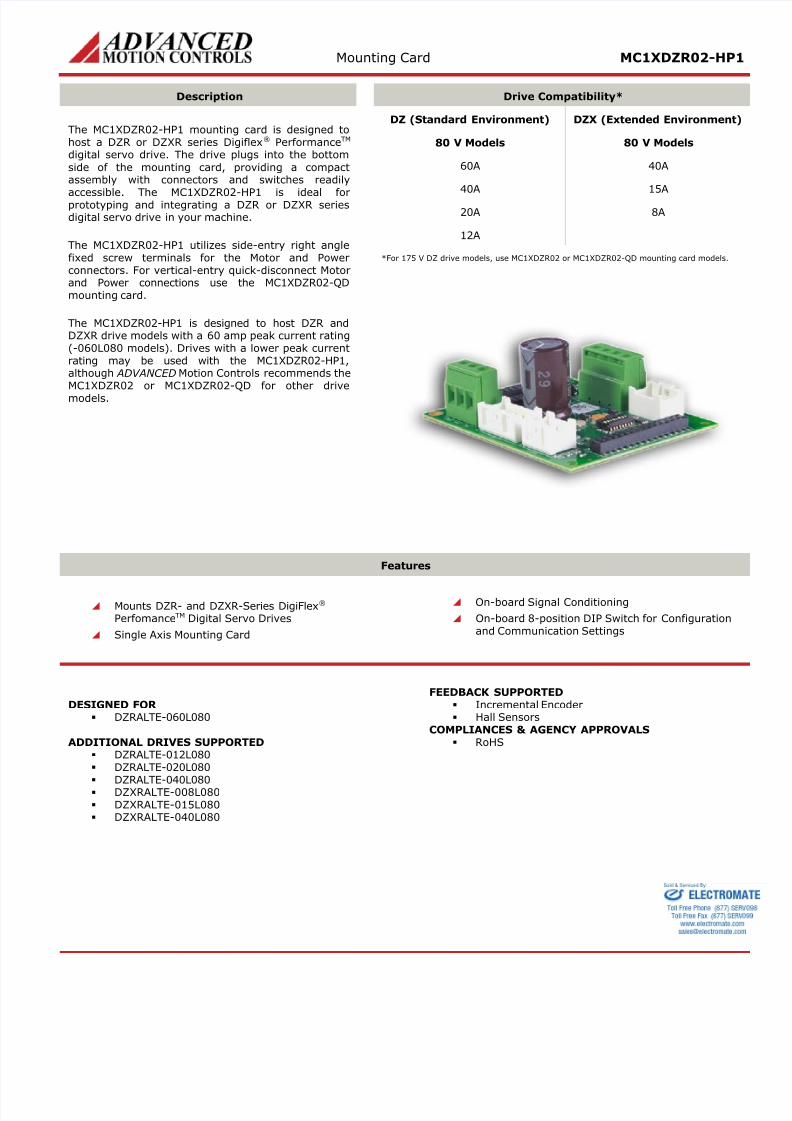
The MC1XDZR02-HP1 mounting card is designed tohost a DZR or DZXR series Digiflex® PerformanceTM digital servo drive. The drive plugs into the bottom
side of the mounting card, providing a compactassembly with connectors and switches readily
accessible. The MC1XDZR02-HP1 is ideal forprototyping and integrating a DZR or DZXR seriesdigital servo drive in your machine.
The MC1XDZR02-HP1 utilizes side-entry right anglefixed screw terminals for the Motor and Powerconnectors. For vertical-entry quick-disconnect Motorand Power connections use the MC1XDZR02-QDmounting card.
The MC1XDZR02-HP1 is designed to host DZR andDZXR drive models with a 60 amp peak current rating(-060L080 models). Drives with a lower peak currentrating may be used with the MC1XDZR02-HP1,although ADVANCED Motion Controls recommends theMC1XDZR02 or MC1XDZR02-QD for other drivemodels.
DZ (Standard Environment) DZX (Extended Enviro
80 V Models 80 V Models
60A 40A
40A 15A
20A 8A
12A
*For 175 V DZ drive models, use MC1XDZR02 or MC1XDZR02-QD mounting card
Features
Mounts DZR- and DZXR-Series DigiFlex® PerfomanceTM Digital Servo Drives
Single Axis Mounting Card
On-board Signal Conditioning
On-board 8-position DIP Switch for Configuand Communication Settings
DESIGNED FOR DZRALTE-060L080
ADDITIONAL DRIVES SUPPORTED DZRALTE-012L080 DZRALTE-020L080 DZRALTE-040L080 DZXRALTE-008L080 DZXRALTE-015L080 DZXRALTE-040L080
FEEDBACK SUPPORTED Incremental Encoder Hall Sensors
COMPLIANCES & AGENCY APPROVALS RoHS
8/11/2019 Advanced Motion Controls Mc1xdzr02-Hp1
http://slidepdf.com/reader/full/advanced-motion-controls-mc1xdzr02-hp1 2/9
Mounting Card MC1XDZR0
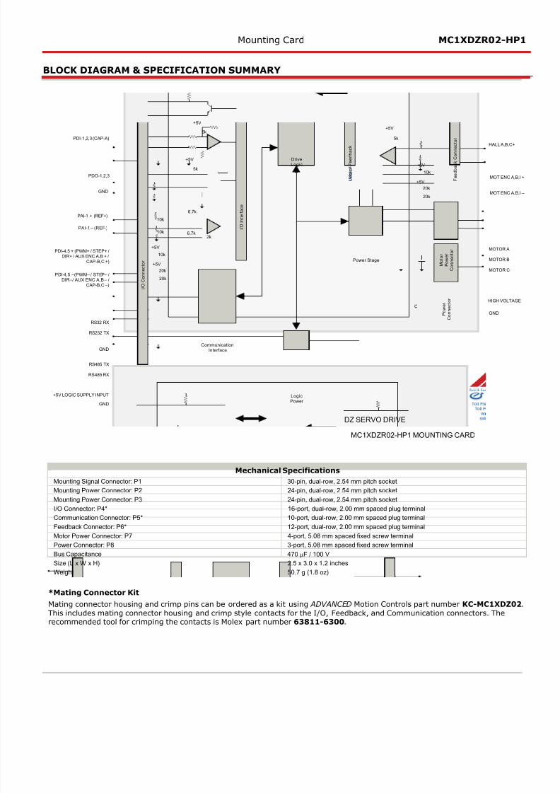
BLOCK DIAGRAM & SPECIFICATION SUMMARY
GND
PDO-1,2,3 MO
MO
HA
RS32 RX
RS232 TX
HIG
MO
MO
MO
GN
M o t o r F e e d b a c k
I / O I n
t e r f a c e
5k
+5V
5k
+5V
6.7k
6.7k2k
5k
+5V
I / O I n
t e r f a c e
Power Stage
DriveLogic
RS485 TX
RS485 RX
M o t o r F e e d b a c k
PDI-1,2,3 (CAP-A)
PDI-4,5 + (PWM+ / STEP+ /DIR+ / AUX ENC A,B + /
CAP-B,C +)
PDI-4,5 –(PWM– / STEP– /DIR–/ AUX ENC A,B – /
CAP-B,C –)
PAI-1 + (REF+)
PAI-1 – (REF-)
DZ SERVO DRIVE
MC1XDZR02-HP1 MOUNTING CARD
F e e d b a c k C o n n e c t o r
M o t o r
P o w e r
C o n n e c t o r
P o w e r
C o n n e c t o r
10k
10k
10k
+5V
20k
20k
+5V
10k
+5V
20k
20k
+5V
+5V LOGIC SUPPLY INPUT
GNDCommunication
Interface
GND
I / O C o
n n e c t o r
LogicPower
C
Mechanical Specifications
Mounting Signal Connector: P1 30-pin, dual-row, 2.54 mm pitch socket
Mounting Power Connector: P2 24-pin, dual-row, 2.54 mm pitch socket
Mounting Power Connector: P3 24-pin, dual-row, 2.54 mm pitch socket
I/O Connector: P4* 16-port, dual-row, 2.00 mm spaced plug terminal
Communication Connector: P5* 10-port, dual-row, 2.00 mm spaced plug terminal
Feedback Connector: P6* 12-port, dual-row, 2.00 mm spaced plug terminal
Motor Power Connector: P7 4-port, 5.08 mm spaced fixed screw terminal
Power Connector: P8 3-port, 5.08 mm spaced fixed screw terminal
Bus Capacitance 470 µF / 100 VSize (L x W x H) 2.5 x 3.0 x 1.2 inches
Weight 50.7 g (1.8 oz)
*Mating Connector Kit
Mating connector housing and crimp pins can be ordered as a kit using ADVANCED Motion Controls part number KC-MC1This includes mating connector housing and crimp style contacts for the I/O, Feedback, and Communication connectors. Trecommended tool for crimping the contacts is Molex part number 63811-6300.
8/11/2019 Advanced Motion Controls Mc1xdzr02-Hp1
http://slidepdf.com/reader/full/advanced-motion-controls-mc1xdzr02-hp1 3/9
Mounting Card MC1XDZR0
PIN FUNCTIONS
P1 – Mounting Signal Connector
This connector mates directly to the drive. For pin functions refer to the drive datasheet.
P2 – Mounting Power Connector
This connector mates directly to the drive. For pin functions refer to the drive datasheet.
P3 – Mounting Power Connector
This connector mates directly to the drive. For pin functions refer to the drive datasheet.
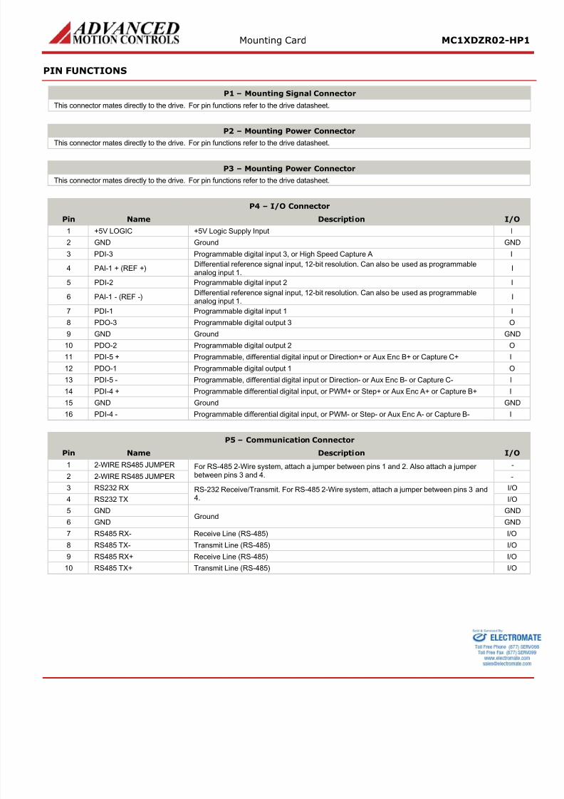
P4 – I/O Connector
Pin Name Description
1 +5V LOGIC +5V Logic Supply Input
2 GND Ground
3 PDI-3 Programmable digital input 3, or High Speed Capture A
4 PAI-1 + (REF +)Differential reference signal input, 12-bit resolution. Can also be used as programmableanalog input 1.
5 PDI-2 Programmable digital input 2
6 PAI-1 - (REF -)Differential reference signal input, 12-bit resolution. Can also be used as programmableanalog input 1.
7 PDI-1 Programmable digital input 1
8 PDO-3 Programmable digital output 3
9 GND Ground
10 PDO-2 Programmable digital output 2
11 PDI-5 + Programmable, differential digital input or Direction+ or Aux Enc B+ or Capture C+
12 PDO-1 Programmable digital output 1
13 PDI-5 - Programmable, differential digital input or Direction- or Aux Enc B- or Capture C-
14 PDI-4 + Programmable differential digital input, or PWM+ or Step+ or Aux Enc A+ or Capture B+
15 GND Ground
16 PDI-4 - Programmable differential digital input, or PWM- or Step- or Aux Enc A- or Capture B-
P5 – Communication Connector
Pin Name Description
1 2-WIRE RS485 JUMPER For RS-485 2-Wire system, attach a jumper between pins 1 and 2. Also attach a jumperbetween pins 3 and 4.2 2-WIRE RS485 JUMPER
3 RS232 RX RS-232 Receive/Transmit. For RS-485 2-Wire system, attach a jumper between pins 3 and4.4 RS232 TX
5 GNDGround
6 GND
7 RS485 RX- Receive Line (RS-485)
8 RS485 TX- Transmit Line (RS-485)
9 RS485 RX+ Receive Line (RS-485) 10 RS485 TX+ Transmit Line (RS-485)
8/11/2019 Advanced Motion Controls Mc1xdzr02-Hp1
http://slidepdf.com/reader/full/advanced-motion-controls-mc1xdzr02-hp1 4/9
Mounting Card MC1XDZR0
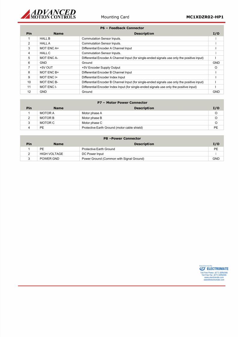
P6 – Feedback Connector
Pin Name Description
1 HALL B Commutation Sensor Inputs.
2 HALL A Commutation Sensor Inputs.
3 MOT ENC A+ Differential Encoder A Channel Input
4 HALL C Commutation Sensor Inputs.
5 MOT ENC A- Differential Encoder A Channel Input (for single-ended signals use only the positive input) 6 GND Ground
7 +5V OUT +5V Encoder Supply Output
8 MOT ENC B+ Differential Encoder B Channel Input
9 MOT ENC I+ Differential Encoder Index Input
10 MOT ENC B- Differential Encoder B Channel Input (for single-ended signals use only the positive input)
11 MOT ENC I- Differential Encoder Index Input (for single-ended signals use only the positive input)
12 GND Ground
P7 – Motor Power Connector
Pin Name Description
1 MOTOR A Motor phase A
2 MOTOR B Motor phase B 3 MOTOR C Motor phase C
4 PE Protective Earth Ground (motor cable shield)
P8 –Power Connector
Pin Name Description
1 PE Protective Earth Ground
2 HIGH VOLTAGE DC Power Input
3 POWER GND Power Ground (Common with Signal Ground)
8/11/2019 Advanced Motion Controls Mc1xdzr02-Hp1
http://slidepdf.com/reader/full/advanced-motion-controls-mc1xdzr02-hp1 5/9
Mounting Card MC1XDZR0
BOARD CONFIGURATION
DIP Switch Functions
Drive Address Settings
Node-ID SW1 SW2 SW3 SW4 SW5 SW
Load from non-volatile memory OFF OFF OFF OFF OFF OF
1 ON OFF OFF OFF OFF OF
2 OFF ON OFF OFF OFF OF
3 ON ON OFF OFF OFF OF
… … … … … … …
63 ON ON ON ON ON ON
RS485 Bit Rate Settings
Bit Rate (bits/sec) SW7
Load from non-volatile memory OFF
9.6K ON
RS485 Termination Node Selection
RS485 Termination SW8
Not Terminated OFF
Terminated ON
LED Functions
The MC1XDZR02-HP1 contains LEDs that indicate DC Power and Logic power supply status. The Power LED will light up wpower is applied to P8-Power Connector, and the Logic LED will light up when the +5 VDC Logic Power is applied to P4-I/OConnector.
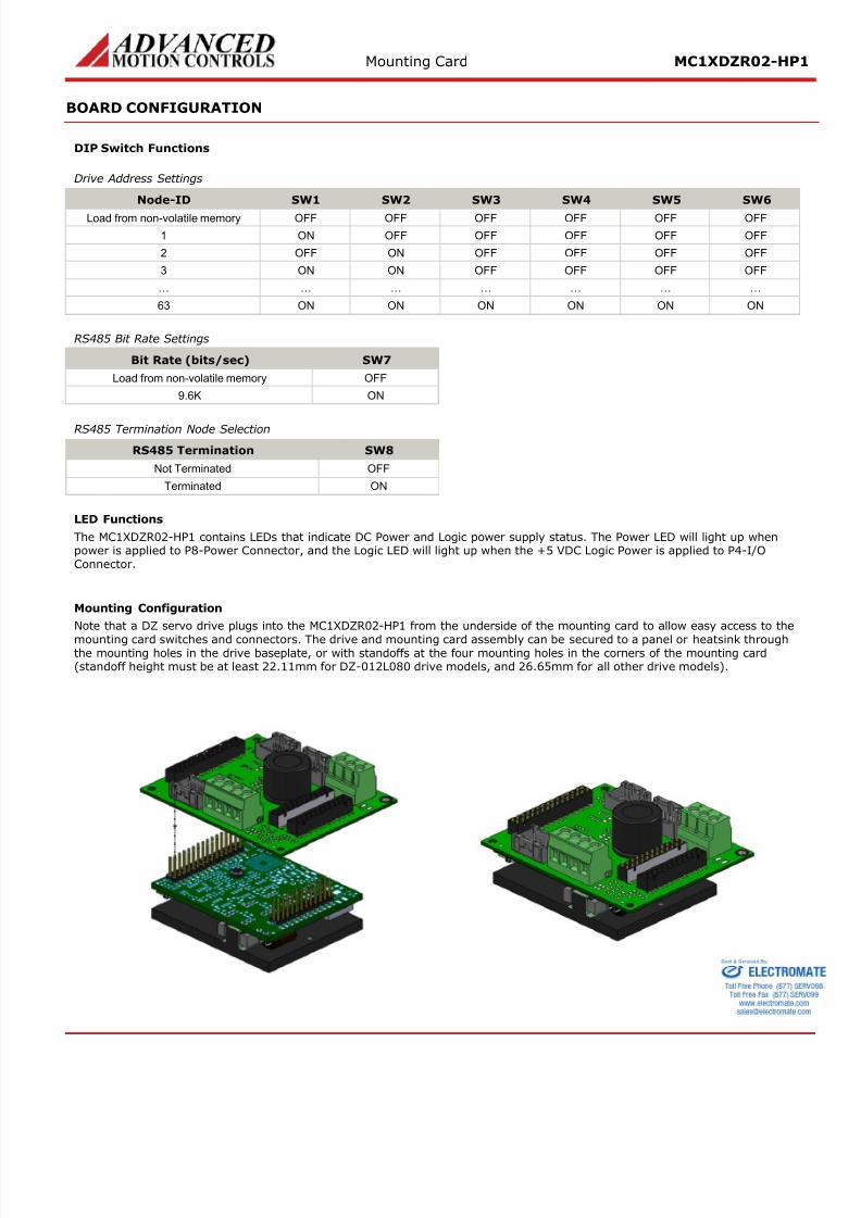
Mounting Configuration
Note that a DZ servo drive plugs into the MC1XDZR02-HP1 from the underside of the mounting card to allow easy access
mounting card switches and connectors. The drive and mounting card assembly can be secured to a panel or heatsink thrthe mounting holes in the drive baseplate, or with standoffs at the four mounting holes in the corners of the mounting car(standoff height must be at least 22.11mm for DZ-012L080 drive models, and 26.65mm for all other drive models).
8/11/2019 Advanced Motion Controls Mc1xdzr02-Hp1
http://slidepdf.com/reader/full/advanced-motion-controls-mc1xdzr02-hp1 6/9
Mounting Card MC1XDZR0
CONNECTOR INFORMATION
P1 – Mounting Signal Connector
Connector Information 30-pin, dual-row, 2.54 mm pitch header
Mating Connector Example No Mating Connector Required. Mate directly to drive
P2 – Mounting Power Connector
Connector Information 24-pin, dual-row, 2.54 mm pitch header
Mating Connector Example No Mating Connector Required. Mate directly to drive
P3 – Mounting Power Connector
Connector Information 24-pin, dual-row, 2.54 mm pitch header
Mating Connector Example No Mating Connector Required. Mate directly to drive
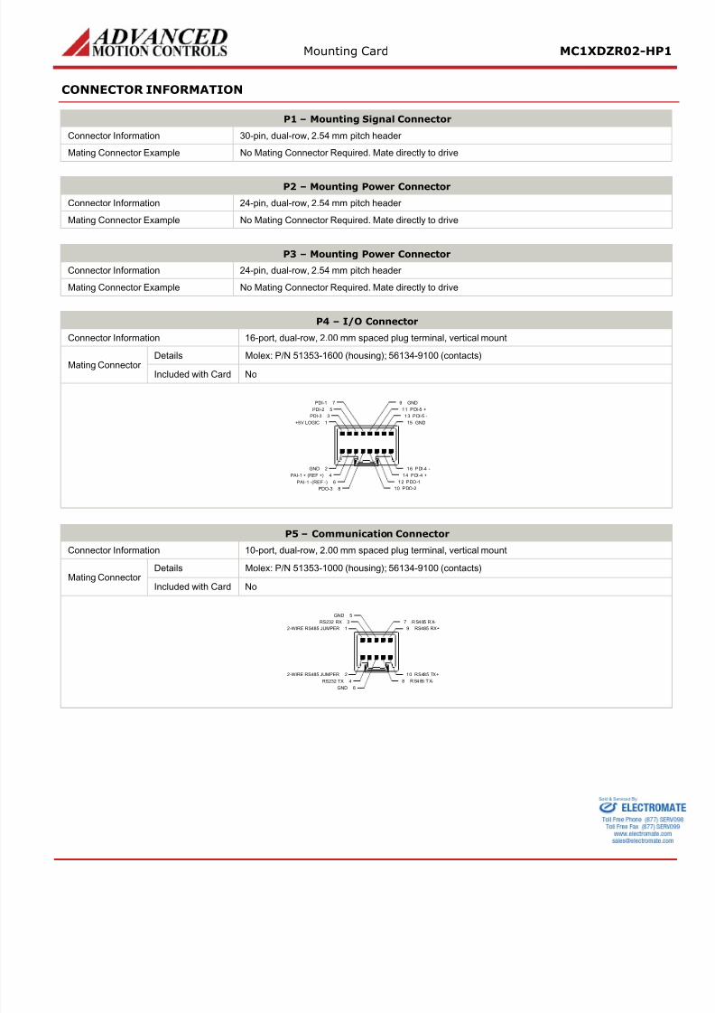
P4 – I/O Connector
Connector Information 16-port, dual-row, 2.00 mm spaced plug terminal, vertical mount
Mating ConnectorDetails Molex: P/N 51353-1600 (housing); 56134-9100 (contacts)
Included with Card No
1+5V LOGIC 15 GND
2GND
3PDI-3
5PDI-2
7PDI-1
13 PDI-5 -
11 PDI-5 +
9 GND
16 PDI-4 -
14 PDI-4 +
12 PDO-1
10 PDO-2
4PAI-1 + (REF +)
6PAI-1 -(REF -)
8PDO-3
P5 – Communication Connector
Connector Information 10-port, dual-row, 2.00 mm spaced plug terminal, vertical mount
Mating ConnectorDetails Molex: P/N 51353-1000 (housing); 56134-9100 (contacts)
Included with Card No
12-WIRE RS485 JUMPER 9 RS485 RX+
22-WIRE RS485 JUMPER
3RS232 RX
5GND
7 RS485 RX-
10 RS485 TX+
8 RS485 TX-4RS232 TX
6GND
8/11/2019 Advanced Motion Controls Mc1xdzr02-Hp1
http://slidepdf.com/reader/full/advanced-motion-controls-mc1xdzr02-hp1 7/9
Mounting Card MC1XDZR0
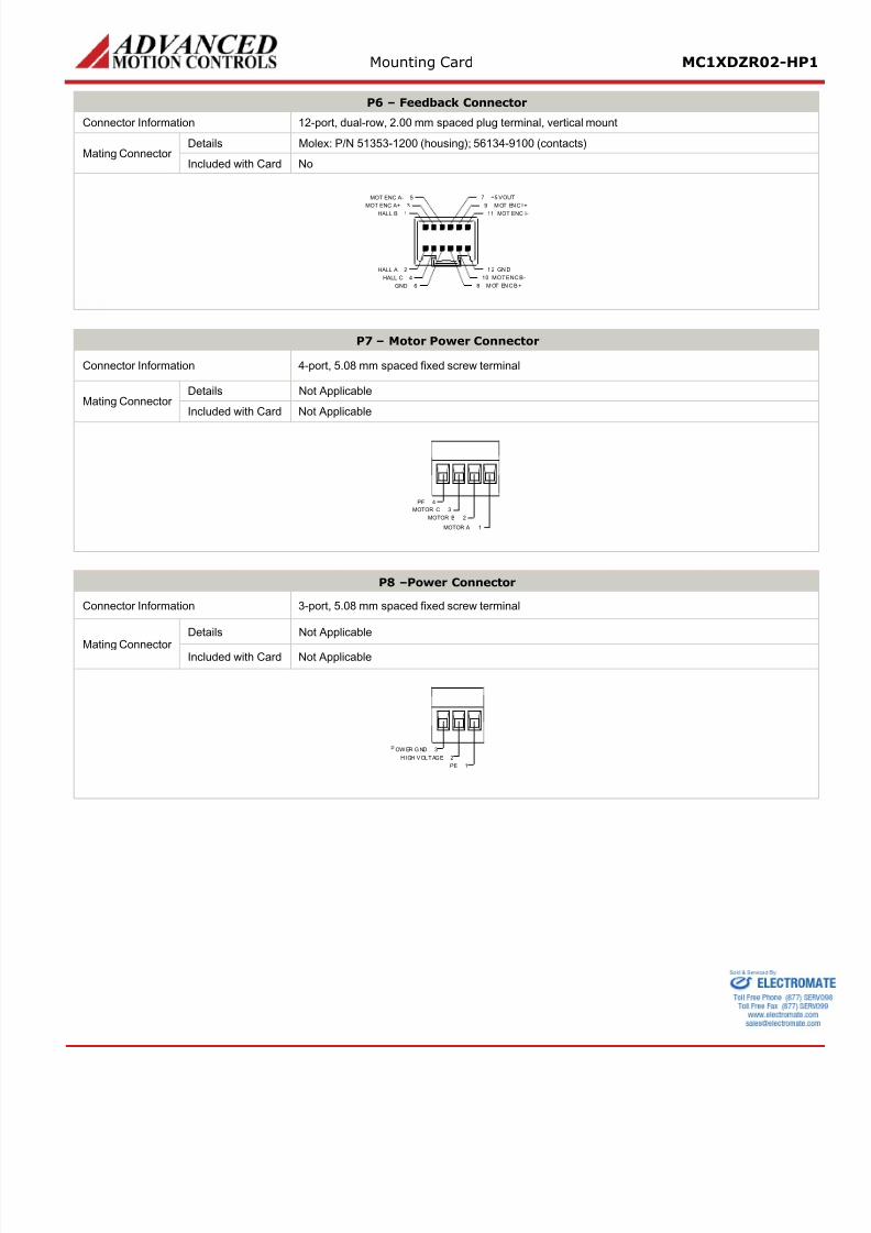
P6 – Feedback Connector
Connector Information 12-port, dual-row, 2.00 mm spaced plug terminal, vertical mount
Mating ConnectorDetails Molex: P/N 51353-1200 (housing); 56134-9100 (contacts)
Included with Card No
1HALL B 11 MOT ENC I-
2HALL A
3MOT ENC A+
5MOT ENC A-
9 M OT ENC I+
7 +5 V OUT
1 2 GN D
10 MOT ENC B-
8 M OT ENC B +
4HALL C
6GND
P7 – Motor Power Connector
Connector Information 4-port, 5.08 mm spaced fixed screw terminal
Mating ConnectorDetails Not Applicable
Included with Card Not Applicable
PE 4
MOTOR C 3
MOTOR B 2
MOTOR A 1
P8 –Power Connector
Connector Information 3-port, 5.08 mm spaced fixed screw terminal
Mating Connector
Details Not Applicable
Included with Card Not Applicable
OW ER G ND 3
HIGH VOLTAGE 2
PE 1
8/11/2019 Advanced Motion Controls Mc1xdzr02-Hp1
http://slidepdf.com/reader/full/advanced-motion-controls-mc1xdzr02-hp1 8/9
Mounting Card MC1XDZR0
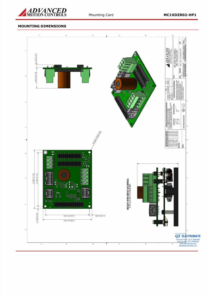
MOUNTING DIMENSIONS
8/11/2019 Advanced Motion Controls Mc1xdzr02-Hp1
http://slidepdf.com/reader/full/advanced-motion-controls-mc1xdzr02-hp1 9/9
Mounting Card MC1XDZR0
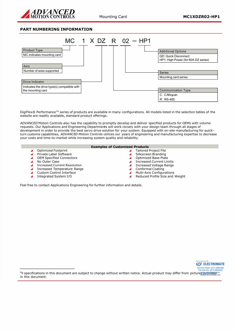
PART NUMBERING INFORMATION
X
Drive Indicator
Indicates the drive type(s) compatible with
the mounting card
Axi s
Number of axes supported
Product Type
MC indicates mounting card
Series
Mounting card series
MC 1 DZ 02
Add it ional Options
QD: Quick Disconnect
HP1: High Power (for 60A DZ serie
HP1R
Communication Type
R: RS-485
C: CANopen
DigiFlex® Performance™ series of products are available in many configurations. All models listed in the selection tables o
website are readily available, standard product offerings.
ADVANCED Motion Controls also has the capability to promptly develop and deliver specified products for OEMs with volumrequests. Our Applications and Engineering Departments will work closely with your design team through all stages ofdevelopment in order to provide the best servo drive solution for your system. Equipped with on-site manufacturing for qturn customs capabilities, ADVANCED Motion Controls utilizes our years of engineering and manufacturing expertise to deyour costs and time-to-market while increasing system quality and reliability.
Examples of Customized Products Optimized Footprint Tailored Project File Private Label Software Silkscreen Branding OEM Specified Connectors Optimized Base Plate No Outer Case Increased Current Limits Increased Current Resolution Increased Voltage Range Increased Temperature Range Conformal Coating
Custom Control Interface
Multi-Axis Configurations Integrated System I/O Reduced Profile Size and Weight
Feel free to contact Applications Engineering for further information and details.
All specifications in this document are subject to change without written notice. Actual product may differ from pictures prin this document