Embed Size (px)
Citation preview
Concha M. ReidGlenn Research Center, Cleveland, Ohio
Advanced Materials and Component Development for Lithium-Ion Cells for NASA Missions
NASA/TM—2012-217689
September 2012
https://ntrs.nasa.gov/search.jsp?R=20120015394 2018-07-15T07:00:52+00:00Z

NASA STI Program . . . in Profi le
Since its founding, NASA has been dedicated to the advancement of aeronautics and space science. The NASA Scientifi c and Technical Information (STI) program plays a key part in helping NASA maintain this important role.
The NASA STI Program operates under the auspices of the Agency Chief Information Offi cer. It collects, organizes, provides for archiving, and disseminates NASA’s STI. The NASA STI program provides access to the NASA Aeronautics and Space Database and its public interface, the NASA Technical Reports Server, thus providing one of the largest collections of aeronautical and space science STI in the world. Results are published in both non-NASA channels and by NASA in the NASA STI Report Series, which includes the following report types: • TECHNICAL PUBLICATION. Reports of
completed research or a major signifi cant phase of research that present the results of NASA programs and include extensive data or theoretical analysis. Includes compilations of signifi cant scientifi c and technical data and information deemed to be of continuing reference value. NASA counterpart of peer-reviewed formal professional papers but has less stringent limitations on manuscript length and extent of graphic presentations.
• TECHNICAL MEMORANDUM. Scientifi c
and technical fi ndings that are preliminary or of specialized interest, e.g., quick release reports, working papers, and bibliographies that contain minimal annotation. Does not contain extensive analysis.
• CONTRACTOR REPORT. Scientifi c and
technical fi ndings by NASA-sponsored contractors and grantees.
• CONFERENCE PUBLICATION. Collected papers from scientifi c and technical conferences, symposia, seminars, or other meetings sponsored or cosponsored by NASA.
• SPECIAL PUBLICATION. Scientifi c,
technical, or historical information from NASA programs, projects, and missions, often concerned with subjects having substantial public interest.
• TECHNICAL TRANSLATION. English-
language translations of foreign scientifi c and technical material pertinent to NASA’s mission.
Specialized services also include creating custom thesauri, building customized databases, organizing and publishing research results.
For more information about the NASA STI program, see the following:
• Access the NASA STI program home page at http://www.sti.nasa.gov
• E-mail your question to [email protected] • Fax your question to the NASA STI
Information Desk at 443–757–5803 • Phone the NASA STI Information Desk at 443–757–5802 • Write to:
STI Information Desk NASA Center for AeroSpace Information 7115 Standard Drive Hanover, MD 21076–1320

Concha M. ReidGlenn Research Center, Cleveland, Ohio
Advanced Materials and Component Development for Lithium-Ion Cells for NASA Missions
NASA/TM—2012-217689
September 2012
National Aeronautics andSpace Administration
Glenn Research CenterCleveland, Ohio 44135
Prepared for theEnergy Tech 2012sponsored by the Institute of Electrical and Electronics EngineersCleveland, Ohio, May 29–31, 2012
Acknowledgments
All of the work presented in this paper was funded by the National Aeronautics and Space Administration, Enabling Technology Development and Demonstration Program High Effi ciency Space Power Systems Project (formerly the Exploration Technology Development Program, Energy Storage Project). Numerous people participated in the synthesis of materials, generation of data, and interpretation of results. Contributions from Richard Baldwin, William Bennett and Brianne Scheidegger, NASA Glenn Research Center; Judith Jeevarajan, NASA Johnson Space Center; and William West, Marshall Smart, Kumar Bugga, and Jessica Soler, NASA Jet Propulsion Lab are gratefully acknowledged. Contributors via efforts funded through NASA Research Announcement NNC08ZP022N include the following: Nader Hagh and Ganesh Skandan; NEI Corporation; Arumugam Manthiram, University of Texas at Austin; Christopher Lang, Physical Sciences, Inc.; Justin Golightly, Lockheed Martin Space Systems Company; Gleb Yushin, Georgia Institute of Technology; Igor Luzinov, Clemson University; Boris Ravdel, Yardney Technical Products; Brett Lucht, University of Rhode Island, and support staff at these companies and universities.
Available from
NASA Center for Aerospace Information7115 Standard DriveHanover, MD 21076–1320
National Technical Information Service5301 Shawnee Road
Alexandria, VA 22312
Available electronically at http://www.sti.nasa.gov
Trade names and trademarks are used in this report for identifi cation only. Their usage does not constitute an offi cial endorsement, either expressed or implied, by the National Aeronautics and
Space Administration.
Level of Review: This material has been technically reviewed by technical management.
This report contains preliminary fi ndings, subject to revision as analysis proceeds.

NASA/TM—2012-217689 1
Advanced Materials and Component Development for Lithium-Ion Cells for NASA Missions
Concha M. Reid
National Aeronautics and Space Administration Glenn Research Center Cleveland, Ohio 44135
Abstract Human missions to Near Earth Objects, such as asteroids, planets, moons, liberation points, and
orbiting structures, will require safe, high specific energy, high energy density batteries to provide new or extended capabilities than are possible with today’s state-of-the-art aerospace batteries. The Enabling Technology Development and Demonstration Program, High Efficiency Space Power Systems Project battery development effort at the National Aeronautics and Space Administration (NASA) is continuing advanced lithium-ion cell development efforts begun under the Exploration Technology Development Program Energy Storage Project. Advanced, high-performing materials are required to provide improved performance at the component-level that contributes to performance at the integrated cell level in order to meet the performance goals for NASA’s High Energy and Ultra High Energy cells. NASA’s overall approach to advanced cell development and interim progress on materials performance for the High Energy and Ultra High Energy cells after approximately 1 year of development has been summarized in a previous paper. This paper will provide an update on these materials through the completion of 2 years of development. The progress of materials development, remaining challenges, and an outlook for the future of these materials in near term cell products will be discussed.
1.0 Introduction NASA is developing High Energy (HE) and Ultra High Energy (UHE) advanced lithium-ion (Li-ion)
cells with the goals of attaining specific energies of 180 watt-hours per kilogram (Wh/kg) and 260 Wh/kg, respectively, when measured at C/10 and 0 °C, in cells that are inherently safe. The HE cell goals are being addressed through the development of advanced cathode components, flame retardant electrolytes, safety devices, and optimized cell designs. The newly developed components will be combined with a commercial graphite anode from Mitsubishi Chemical Corporation (MPG-111) that can achieve a specific capacity of 330 milliampere-hours per gram (mAh/g) at C/10 and 0 °C and a commercial battery-grade separator to comprise an HE cell design. The UHE cell goals will be achieved through the development of advanced anodes and combining them with the cathode, safety device, and separator utilized in the HE cell. A flame retardant electrolyte specially formulated to be compatible with the advanced anode will be used in the UHE cell design. Background information on the cell chemistries, their components, and cell designs are documented in prior papers by Reid and Bennett and by Reid (Refs. 1 and 2).
A table of Key Performance Parameters (KPPs) is shown in Table 1. These KPPs establish target criteria for the performance of cell components and Li-ion cells, and project the expected performance of a battery-level system comprised of the cells under development. State-of-the art (SOA) is based on aerospace design Li-ion cells and batteries developed by Yardney Technical Products for operation on the Mars Exploration Rovers (MER).

NASA/TM—2012-217689 2
TABLE 1.—KEY PERFORMANCE PARAMETERS Performance
parameter State of the Art Current value Threshold valuea Goala
No fire or flame
Instrumentation/controllers used to prevent unsafe conditions. There is no non-flammable electrolyte in SOA
Preliminary results indicate a small reduction in performance using safer electrolytes and cathode coatings
Tolerant to electrical and thermal abuse such as over-temperature, over- charge, reversal, and short circuits with no fire or thermal runawayc
Tolerant to electrical and thermal abuse such as over-temperature, over- charge, reversal, and short circuits with no fire or thermal runawayc
Battery-level specific energy,b (Wh/kg)
90 Wh/kg at C/10 and 30 °C 83 Wh/kg at C/10 and 0 °C (MER rovers)
160 at C/10 and 30 °C (HE) 170 at C/10 and 30 °C (UHE) 80 Wh/kg at C/10 and 0 °C (predicted)
135 Wh/kg at C/10 and 0 °C “High-Energy” 150 Wh/kg at C/10 and 0 °C “Ultra-High Energy”
150 Wh/kg at C/10 and 0 °C “High-Energy” 220 Wh/kg at C/10 and 0 °C “Ultra-High Energy”
Cell-level specific energy, (Wh/kg)
130 Wh/kg at C/10 and 30 °C 118 Wh/kg at C/10 and 0 °C
199 at C/10 and 23 °C (HE) 213 at C/10 and 23 °C (UHE) 100 Wh/kg at C/10 and 0 °C (predicted)
165 Wh/kg at C/10 and 0 °C “High-Energy” 180 Wh/kg at C/10 and 0 °C “Ultra-High Energy”
180 Wh/kg at C/10 and 0 °C “High-Energy” 260 Wh/kg at C/10 and 0 °C “Ultra-High Energy”
Cathode-level specific capacity, (mAh/g)
180 mAh/g 252 mAh/g at C/10 and 25 °C 190 mAh/g at C/10 and 0 °C
260 mAh/g at C/10 and 0 °C
280 mAh/g at C/10 and 0 °C
Anode-level specific capacity, (mAh/g)
280 mAh/g (MCMB) 330 at C/10 and 0 °C (HE) 1200 mAh/g at C/10 and 0 °C for 10 cycles (UHE)
600 mAh/g at C/10 and 0 °C “Ultra-High Energy”
1000 mAh/g at C/10 0 °C“Ultra-High Energy”
Battery-level energy density
250 Wh/l n/a 270 Wh/l “High-Energy” 360 Wh/l “Ultra-High”
320 Wh/l “High-Energy” 420 Wh/l “Ultra-High”
Cell-level energy density
320 Wh/l n/a 385 Wh/l “High-Energy” 460 Wh/l “Ultra-High”
390 Wh/l “High-Energy” 530 Wh/l “Ultra-High”
Operating temperature
–20 to +40 °C 0 to +30 °C 0 to 30 °C 0 to 30 °C
aAssumes prismatic cell packaging for threshold values. Goal values include lightweight battery packaging. bBattery values are assumed at 100% depth-of-discharge (DoD), discharged at C/10 to 3.0 volts/cell, and at 0 °C operating conditions. cOver-temperature up to 110 °C; reversal 150% excess discharge at 1C; pass external and simulated internal short tests; overcharge 100% at 1C for Goal and 80% at C/5 for Threshold Value.
NASA Research Announcement (NRA) contracts that were initiated specifically to develop components targeted for the HE and UHE cells have concluded after a two-year period of effort. Electroactive materials, electrodes, sample coupons, and electrolytes were delivered to NASA at intervals of 6, 11, 18, and 23 months (mo.) into their development and were independently assessed by NASA Glenn Research Center (GRC), Johnson Space Center (JSC), and/or Jet Propulsion Laboratory (JPL) according to standard procedures established for this development project. These materials will be referred to as 6, 11, 18, and 23 mo. deliverables/materials. The progression of the performance of the materials over the development timeframe will be discussed in this paper. Comparisons of the materials’ performance relative to the goal values will be discussed, parameters that are on target with the goal criteria will be highlighted, and areas where technical advancement is still required will be identified. Additionally, projected characteristics of cells incorporating these materials will be presented.

NASA/TM—2012-217689 3
2.0 High Energy Cell 2.1 Cathodes
Advanced cathodes are critical to the development of high specific energy HE and UHE cells. Layered transition metal oxide materials containing lithium, nickel, manganese, and cobalt (Li[LiNMC]O2) are being developed with the goal to attain 280 mAh/g when discharged at C/10 and 0 °C to 3.0 volts (V). The cathode materials discussed in this paper were developed at the University of Texas at Austin (UTA) and at NEI Corporation (NEI).
UTA’s focus has been to systematically investigate solid solutions of (1-z)[Li1/3Mn2/3]O2-zLi[Ni1-x-y MnxCoy]O2 to identify and optimize lithium-rich, layered compositions that can meet the goals stated above. The composition Li[Li0.2Mn0.54Ni0.13Co0.13]O2 was targeted as the stoichiometry that could potentially offer the desired specific capacity. Improvement in irreversible capacity loss (ICL) (reduction of), discharge capacity, and rate capability were achieved through surface modifications (e.g., application of coatings) using solution-based processes and blending the base material with lithium-free insertion hosts (Ref. 3). NEI’s approach to cathode development has been the design and synthesis of two-dimensional layered electrodes based on a composite of Li[Li1/3Mn2/3]O2 and Li[Mn1/3Ni1/3Co1/3]O2 (Ref. 4).
UTA and NEI materials were independently assessed at NASA JPL using a standard set of test conditions in 2032-type coin cell half cells with a Li metal electrode, 1.0 molar (M) lithium hexafluorophoshate (LiPF6) in ethylene carbonate:diethyl carbonate:dimethyl carbonate (EC:DEC:DMC) electrolyte in a 1:1:1 ratio by volume (baseline electrolyte), and a 20 micron (µm) thick Tonen Setela (Toray Tonen) separator, unless otherwise noted. Cathode test procedures are given in Table 2.
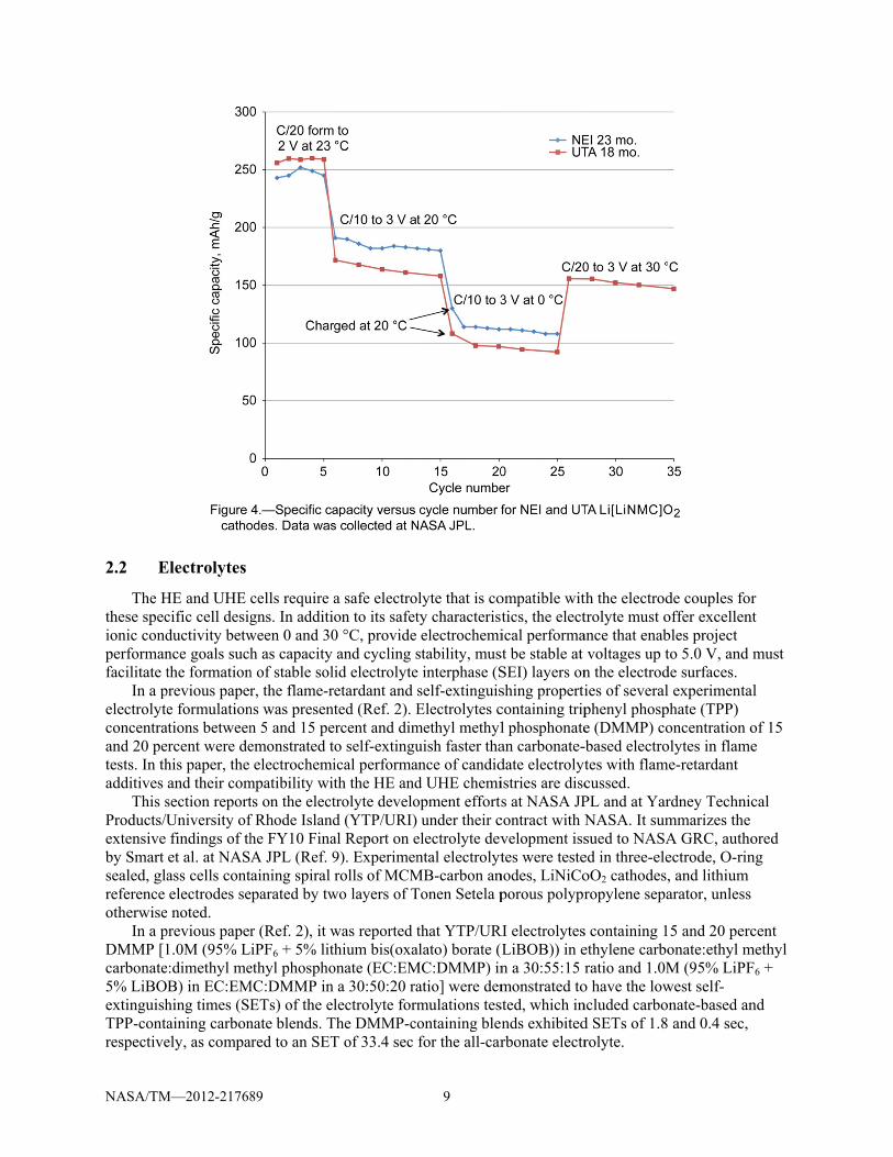
The performance against key metrics that are fundamental to the overall characterization of the cathodes has been exhibiting gradual improvement over the course of 2 years. The “best” values demonstrated for these parameters are compared to the goal values on the “spider plot” shown in Figure 1. Best values are defined as the highest value of the particular parameter achieved over the two-year development period. Hence, values are not necessarily for the same material. Table 3 quantitatively lists the best and goal values and the materials from which the best values were measured. In addition, it lists the values of all the parameters for the most recent deliverables from each developer. Values reported are for the average of four cells, with the exception of the UTA 11 mo. material, whose value is the average of two cells. The parameters shown include first cycle reversible capacity, specific capacity, temperature performance, tap density, rate capability, and cycle life. The following paragraphs describe the data for these parameters in more detail.
TABLE 2.—CATHODE TEST PROCEDURES Test stage Test conditions
Formation At 23 °C, charge at C/20 to 4.8 V, hold voltage, and allow current to taper to C/50. Rest for 15 min. Discharge at C/20 to 2V. Perform for 5 cycles.
20 °C Characterization At 20 °C, charge at C/10 to 4.8 V, hold voltage, and allow current to taper to C/50. Rest for 15 min. Discharge at C/10 to 2V. Perform for 10 cycles.
0 °C Characterization First charge is performed at 20 °C. All other charges are performed at 0 °C. Charge at C/10 to 4.8 V, hold voltage, and allow current to taper to C/50. Rest for 15 min. Soak for a minimum of 2 hours after a temperature change. At 0 °C, discharge at C/10 to 2V. Perform for 10 cycles.
30 °C Characterization Soak at 30 °C for a minimum of 2 hours after a temperature change. Charge at C/10 to 4.8 V, hold voltage, and allow current to taper to C/50. Rest for 15 min. Discharge at C/10 to 2V. Perform for 10 cycles.

NASA/TM
First cycle Specific caSpecific caRT capacitTap density
Rate capabProjected c
initial caProjected c
initial ca
2.1.1 RFirst-c
reversiblecycled bet
%
The g
ideally beof lithiuminternal Ncapacity o
M—2012-21768
TABLMetric
reversible capacapacity, RT, C/10apacity, 0 °C, C/ty retention at 0 y (g/cc)
bility at C/5 as cocycle life for HEapacity) cycle life for UHapacity)
Reversible Cacycle reversib
e capacity is etween 2.0 V a
%
goal for first ce no greater th
m nickel cobalNASA measurof 87 percent.
89
LE 3.—SUMMAc
city (%) 0 to 3V (mAh/g)10 to 3V (mAh/g°C (%)
ompared to C/10E (cycles to 80%
HE (cycles to 80%
apacity ble capacity iequivalent to (and 4.8 V, wh
cycle reversibhan 19 percenlt aluminum orements. The Changes to s
ARY OF CATHOGoal
V
81 ) 311 g) 280
90 >1.5
0 (%) 95 of 2000
% of 250
s measured on(100 percent mhere percent I
100, where c
le capacity isnt. This value oxide, a standUTA Li[LiNMsynthesis tech
4
ODE BEST VALBest
Value
87 UTA 18238 UTA 11135 UTA 1172 UTA 23
>2.3 NEI anduncoat
83 NEI 6 m81 UTA
81 UTA
n the initial fominus the perICL is given b
charge = charge
81 percent, ois based on tyard lithium-ioMC]O2 mater
hniques and c
ALUES AND LAt values
Material
8 and 23 mo. coa mo. uncoated mo. coated
3 mo. coated d UTA, both 18 mted
mo. uncoated
formation cycrcentage of fiby the followi
capacity, and di
or inversely, typical results on cathode mrials have exhoating chemi
ATEST VALUESValues
UTA 23 coated
ated 87 164 126 85
mo. 2.02
Not measNot meas
Not meas
le. The perceirst-cycle ICLing equation:
ischarge = disch
the first cycle for the first c
material, and whibited a first istry were inst
S for latest materimo. d
NEI 23uncoa
6519113072
1.34
sured Not measured Not mea
sured Not mea
ntage of first L) as the cell i
harge capacity
e ICL should cycle reversib
was verified bcycle reversitrumental in
ials mo.
ated 1 0 4
asuredasured
asured
cycle is
bility y ible

NASA/TM—2012-217689 5
improving the reversible capacity from the 50 to 75 percent values exhibited in early deliverables to NASA.
2.1.2 Specific Capacity Specific capacity at 20 and 0 °C are plotted as a percentage of the specific capacity goals at C/10 and
3.0 V and the respective temperature. Specific capacity at 20 °C is reported for the first cycle following formation. Discharge was continued to 2.0 V and values were measured and reported at 3.0 V. Studies performed internally at NASA JPL have shown that there is a slightly higher rate of capacity fade with certain Li[LiNMC]O2 materials when they are cycled between 4.7 and 2.0 V as opposed to between 4.7 and 3.0 V. However, cycling to 2.0 V provides valuable information on the residual capacity remaining between 3.0 and 2.0 V.
The best specific capacity measured at 20 °C and C/10 from 4.7 to 3.0 V is 238 mAh/g, which is 77 percent of the goal value of 311 mAh/g. Since project goals were established for 0 °C operation, the room temperature (RT) goal was derived from the 0 °C specific capacity goal, based on the desire to retain at least 90 percent of RT capacity when operating at 0 °C. In this paper, temperatures between 20 and 23 °C are considered RT.
Testing at 0 °C is performed after cycling ten times at 20 °C. Specific capacity at 0 °C is reported for the first discharge at 0 °C, after a charge at 20 °C. As with the 20 °C cycling, discharge was continued to 2.0 V and values were measured and reported at 3.0 V. At 0 °C and C/10 from 4.7 to 3.0 V, 135 mAh/g was obtained, only 48 of the goal value of 280 mAh/g. Since capacity at 0 °C is measured on the 11th operational cycle (after 20 °C cycling), some capacity fade occurred prior to obtaining the measurement at 0 °C. Experimentally, an 18-24 mAh/g decrease was typically observed from the first 20 °C discharge to the tenth 20 °C discharge. If the specific capacity delivered at 0 °C is adjusted for the capacity loss due to earlier cycling, the value approaches 57 percent of the goal.
2.1.3 Temperature Performance Temperature performance is measured as the percentage of RT capacity retained at 0 °C. Excessive
capacity loss at lower temperatures can limit the practical design of a battery that must operate at those temperatures. In such a case, in order to supply enough operational capacity, a battery may need to be oversized to compensate for the decrease in delivered capacity at low temperatures. Alternately, thermal management must be designed in as part of the battery system to maintain the operating point at a warmer temperature. Either of these options may increase the mass of the battery system unless the battery load can be handled as part of a larger, integrated thermal management system, for example, as part of a vehicle’s thermal management system.
Nonetheless, it is desirable to retain as much of the RT capacity when operating at 0 °C as possible. A goal of 90 percent was established for temperature performance based on what is reasonably practical given current SOA Li-ion cell performance. The specific capacity goals discussed in the previous section already take into account a 10 percent difference in temperature performance from 20 to 0 °C. Therefore, if 0 °C goals are met yet temperature performance is <90 percent, it is acceptable since in such a case the 20 °C performance would exceed its goal.
2.1.4 Tap Density Tap density (TD), a measure of how well powders are able to be packed closely together, is a key
attribute to measure in the determination of a material’s suitability for the fabrication of cathodes from raw powders. To determine tap density, powders are placed in a graduated cylinder and taps are applied by automated equipment to compress the powder. The mass per unit volume is then measured on the compressed sample. The TD of the powders should ideally be > 1.5-1.6 grams per cubic centimeter (g/cc) for manufacturability of cathodes of practical thickness on production equipment at Saft America, NASA’s industrial partner for building HE and UHE cells.

NASA/TM—2012-217689 6
Low tap density also impedes a material’s ability to achieve high energy density, independently of production processes (Ref. 13). Materials that do not compress well contain more air between their particles, so they have high porosity when packed. These materials are unable to highly loaded (loading = capacity per unit area), since not enough material can occupy a unit area, resulting in low energy density.
2.1.5 Rate Capability Rate capability is a measure of a material’s ability to charge and/or discharge at specified currents.
Rate capability was not routinely measured on cathodes. Studies were performed on early materials (NEI 6 mo.) to baseline the rate performance of this class of layered Li[LiNMC]O2 materials. There is no specific requirement for rate capability at C/5 as compared to C/10 for the HE and UHE cells. However, for practical operation in a cell, the cathode should retain a significant portion of the C/10 capacity when operating at C/5. A target of 95 percent of the C/10 performance was set for the C/5 performance.
2.1.6 Cycle Life Cycle life is the amount of cycles a cell delivers under specified conditions. Cycle life can vary
depending upon how an electrode/cell is utilized. For these materials, the cycle life goals specify that the cathode should deliver at least 250 cycles until the point that 80 percent of its initial capacity is reached. Cycle life assessments are only performed on materials that demonstrate acceptable characteristics in other areas, however, NASA has collected limited data on selected deliverables to baseline this performance. Eighty-one cycles to 80 percent of initial capacity were projected from 60 cycles of data collected on experimental coated materials tested in coin cell half cells at UTA. A constant per cycle decrease in ampere-hour capacity was used for this projection.
Literature reports similar trends in capacity fade for this class of materials. Li et al. report 80 cycles to 80 percent of first cycle capacity when cycling at C/5 at 20 °C between 4.8 and 2.5 V (Ref. 5). They show that a rapid decrease in capacity occurs within the first 30 cycles, then the rate of fade decreases substantially for 70 more cycles. This is similar to the effect seen in some UTA coated materials. Li et al. also observed that this rapid decrease in capacity during early cycling occurred independently of discharge rate.
NEI also reports rapid fade in their “V2” materials (11 and 18 mo. deliverables) during early cycling before cycling stabilizes (Ref. 6). Hagh et al., attribute this phenomenon to an impedance rise rather than to intrinsic capacity loss. This suggests that if the impedance rise mechanism that occurs in early cycling can be overcome, less fade and better cycling stability can be obtained, which will extend cycle life.
2.1.7 Discussion While NMC materials have potential to offer much higher specific capacity than traditional Li-ion
cathodes such as lithium cobalt oxide (LiCoO2), the Li[Li1/3Mn2/3]O2 component of the NMC material has insulating properties that impacts its electronic conductivity. Additionally, a thick SEI layer is formed at the higher operating voltages, leading to slow kinetics and impacting the rate of lithium ion diffusion and charge transfer. These factors all lead to lower rate capability in the NMC cathode than is typically seen with other Li-ion chemistries (Ref. 14). Temperature performance is also much worse with NMC materials than with other lithium-ion chemistries, attributable to slow kinetics at low temperatures.
Figure 2 and Figure 3 contain spider plots that show the progression of the material properties as measured by the parameters discussed above for 6, 11, 18, and 23 mo. materials from UTA and NEI. Values plotted in each graph pertain to a single material. Although clear progress in materials development has been demonstrated over the past 2 years, component performance has still not achieved the goals necessary to enable the performance targets for the HE and UHE cells. For cathodes, most notably, specific capacity and cycle life are well below necessary targets. Results for specific capacity versus cycle number for representative materials delivered from each company are shown in Figure 4.

NASA/TM
Throufrom one This is morevealed trefocusedfirst of thewith non-ranging fr
NEI ialtered thepacking denvironm
M—2012-21768
ughout the devdelivery perioost evident inthat TD was t
d to utilize catese deliverabldestructive blrom 1.8 to 2.3mproved the e particle mor
density (Ref. 4ent) also resu
89
velopment ofod to the next
n the 18 mo. moo low to allothode materiales was receivlending of pre3 g/cc (Ref. 3)TD of their 1rphology from4). Experimenulted in TD im
f NMC cathodt while the de
materials. Durow for the pro
al synthesis mved at 18 mo.ecipitated pre). 8 and 23 mo.
m irregular pantation with dmprovements.
7
de materials, peveloper focusring analysis ooduction of vi
methods that w Hydroxide p
ecursors were
. materials viaarticles to unidifferent anne
performance sed upon impof early mateiable cathode
would yield mprecipitation s used to form
a micro-structiform sphericaealing atmosph
of some paraprovement in erials, manufaes. Hence, at U
materials with synthesis proc
mulate materia
tural modifical particles thheres (other t
ameters sufferother parame
acturability stuUTA, efforts higher TD. Tcedures combals with TD
ations. They hat provided hthan an air
red eters. udies were
The bined
higher

NASA/TM
Althoatmospherhad previothat they sis favorabfacilitateshigher TDlower spe
OptimmaintainincombinatiUHE cell
M—2012-21768
ough experimeres resulted inously been desuffered from
ble to electroc the charge tr
D materials necific capacity
mizations werng tap densityion of the attrchemistries.
89
entation with n materials wemonstrated. M
m noticeably lochemical perforansfer procesegatively impy. e subsequently at or above ributes discus
alternative sywith higher TD
Measurementower surface ormance in thss of lithium iacted the elec
ly performed the minimumsed above in
8
ynthesis technD, these materts performed area than thei
hat it providesions (Refs. 7 actrochemical
at UTA and Nm required for
one material
niques, particrials exhibitedat NEI on their lower TD cs a larger elecand 8). The loperformance
NEI to maximr manufacturais critical for
cle morphologd lower specie higher TD mcounterparts. ctrode-electroow surface arof the materi
mize specific ability. The acr the success o
gy, and anneaific capacity tmaterials reveHigh surface
olyte interfacerea observed iials, resulting
capacity whichievement ofof the HE and
aling than ealed
area e and in the in
le f the d
NASA/TM
2.2 E
The Hthese specionic condperformanfacilitate t
In a pelectrolyteconcentraand 20 petests. In thadditives
This sProducts/Uextensive by Smart sealed, glareference otherwise
In a pDMMP [1carbonate5% LiBOextinguishTPP-contarespective
M—2012-21768
Electrolytes
HE and UHE cific cell desigductivity betwnce goals suchthe formation
previous papere formulation
ations betweenercent were dehis paper, the and their comsection reportUniversity offindings of thet al. at NASass cells contelectrodes se
e noted. previous paper1.0M (95% Le:dimethyl meB) in EC:EMhing times (SEaining carbonely, as compa
89
cells require agns. In additiween 0 and 30h as capacity
n of stable solr, the flame-r
ns was presentn 5 and 15 peemonstrated telectrochemi
mpatibility witts on the electf Rhode Islandhe FY10 FinaA JPL (Ref. 9aining spiral
eparated by tw
r (Ref. 2), it wiPF6 + 5% lith
ethyl phosphoMC:DMMP in
ETs) of the elnate blends. Tared to an SET
a safe electroon to its safet0 °C, provideand cycling sid electrolyteetardant and sted (Ref. 2). E
ercent and dimo self-extinguical performath the HE andtrolyte develod (YTP/URI) al Report on e9). Experimenrolls of MCM
wo layers of T
was reported thium bis(oxa
onate (EC:EMa 30:50:20 ra
lectrolyte formThe DMMP-coT of 33.4 sec
9
lyte that is coty characteristelectrochemi
stability, muse interphase (Sself-extinguisElectrolytes c
methyl methyluish faster thaance of candidd UHE chemiopment efforts
under their celectrolyte devntal electrolyt
MB-carbon anTonen Setela p
that YTP/URalato) borate (
MC:DMMP) inatio] were demmulations tesontaining blenfor the all-car
ompatible wittics, the electical performast be stable at SEI) layers onshing properticontaining tripl phosphonatean carbonate-date electrolytistries are discs at NASA JP
contract with Nvelopment isstes were teste
nodes, LiNiCoporous polypr
RI electrolytes(LiBOB)) in en a 30:55:15 rmonstrated tosted, which innds exhibitedrbonate electr
th the electrodtrolyte must oance that enab
voltages up tn the electrodies of severalphenyl phospe (DMMP) co-based electrotes with flamcussed. PL and at YarNASA. It sumsued to NASAed in three-eleoO2 cathodes,ropylene sepa
s containing 1ethylene carboratio and 1.0M
o have the lowncluded carbod SETs of 1.8rolyte.
de couples foroffer excellenbles project to 5.0 V, and de surfaces. l experimentaphate (TPP) oncentration oolytes in flame
me-retardant
rdney Technicmmarizes the A GRC, authoectrode, O-rin, and lithium arator, unless
5 and 20 perconate:ethyl mM (95% LiPFwest self-nate-based an and 0.4 sec,
r nt
must
al
of 15 e
cal
ored ng
cent methyl F6 +
nd
NASA/TM
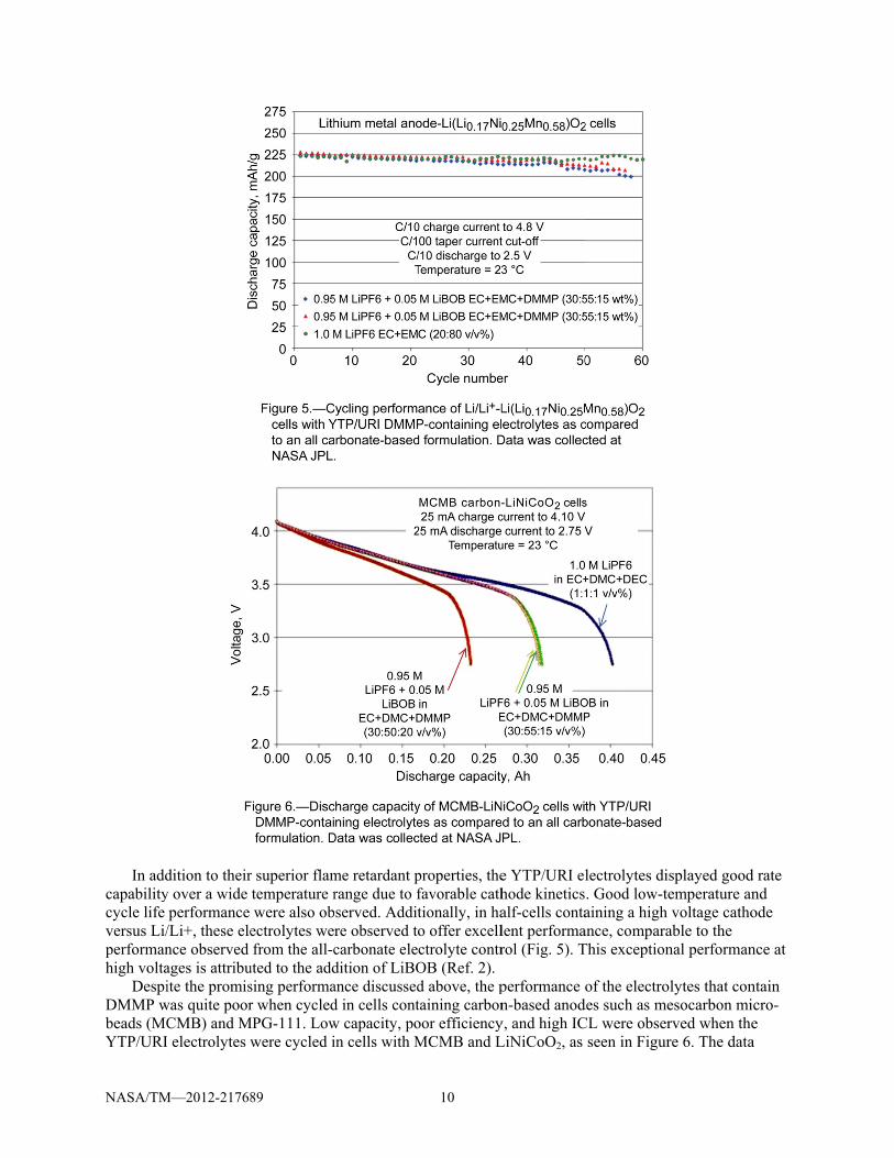
In add
capabilitycycle life versus Li/performanhigh volta
DespiDMMP wbeads (MCYTP/URI
M—2012-21768
dition to theiry over a wide
performance /Li+, these elence observed ages is attribuite the promis
was quite poorCMB) and MI electrolytes w
89
r superior flamtemperature rwere also ob
ectrolytes wefrom the all-c
uted to the addsing performar when cycled
MPG-111. Lowwere cycled i
me retardant prange due to fserved. Additre observed tocarbonate eledition of LiBOance discussedd in cells contw capacity, poin cells with M
10
properties, thefavorable cathtionally, in hao offer excellctrolyte contrOB (Ref. 2). d above, the ptaining carbonoor efficiencyMCMB and L
e YTP/URI elhode kineticsalf-cells contalent performarol (Fig. 5). T
performance on-based anod
y, and high ICLiNiCoO2, as
lectrolytes dis. Good low-teaining a high
ance, comparaThis exception
of the electrodes such as meCL were obser
seen in Figur
splayed goodemperature anvoltage catho
able to the nal performan
lytes that conesocarbon mirved when there 6. The data
d rate nd ode
nce at
ntain cro-e a
NASA/TM
shown repDMMP onwhile cellcapacity oexcessive DMMP-c
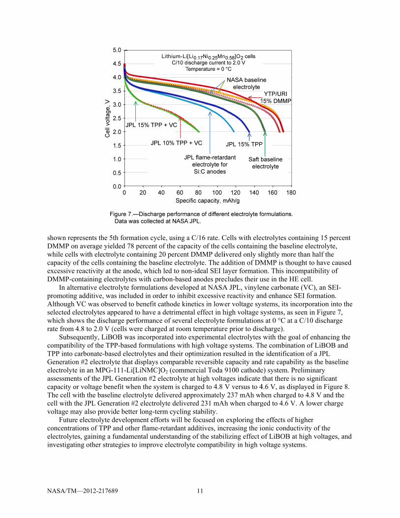
In altepromotingAlthough selected ewhich shorate from
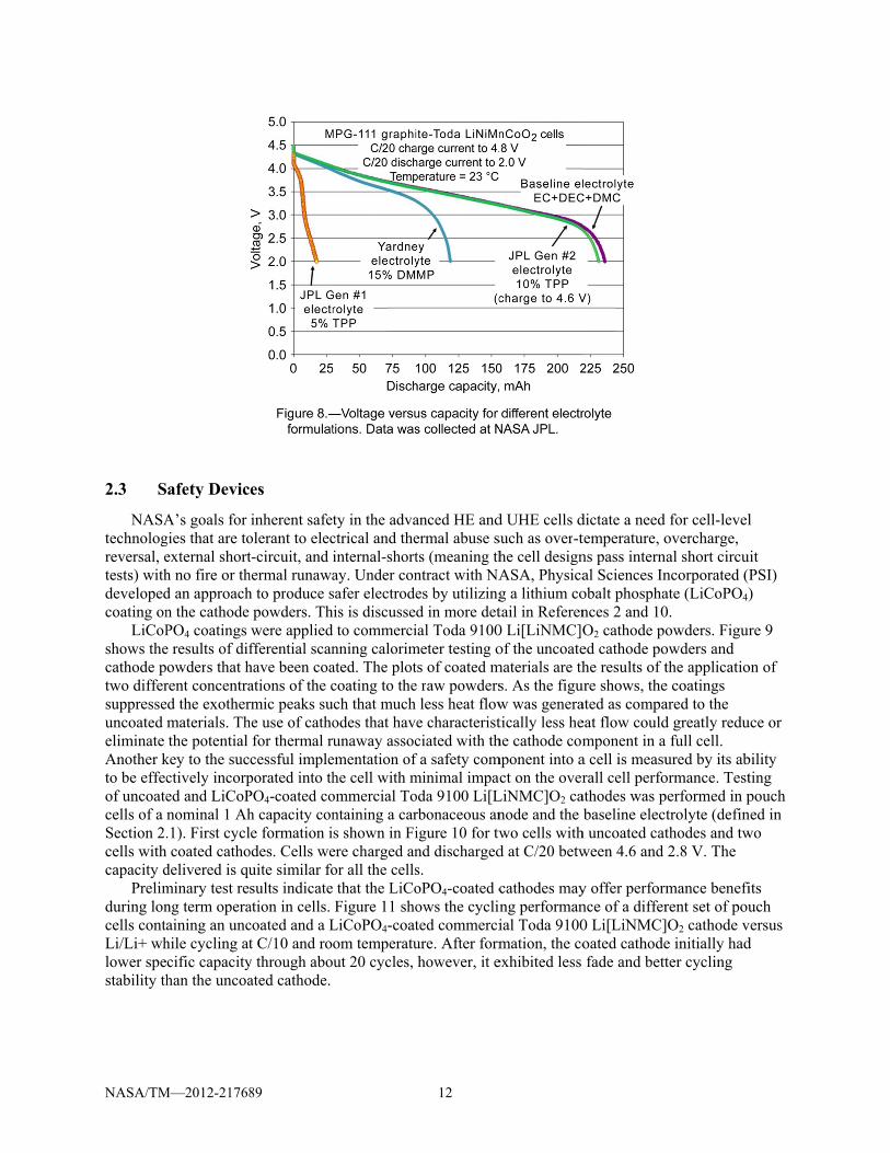
SubsecompatibiTPP into cGeneratioelectrolyteassessmencapacity oThe cell wcell with tvoltage m
Futurconcentraelectrolyteinvestigat
M—2012-21768
presents the 5n average yiels with electroof the cells coreactivity at ontaining eleernative electg additive, waVC was obse
electrolytes apows the disch4.8 to 2.0 V (
equently, LiBility of the TPcarbonate-bas
on #2 electrolye in an MPG-nts of the JPLor voltage benwith the baselthe JPL Gene
may also provie electrolyte d
ations of TPP es, gaining a ting other stra
89
5th formation elded 78 perceolyte containiontaining the bthe anode, whctrolytes withtrolyte formulas included inerved to beneppeared to havarge performa(cells were chOB was incor
PP-based formsed electrolytyte that displa-111-Li[LiNM
L Generation #nefit when theine electrolyt
eration #2 elecide better longdevelopment and other flamfundamental
ategies to imp
cycle, using aent of the capng 20 percentbaseline electhich led to noh carbon-baselations develon order to inhifit cathode kive a detrimenance of severharged at roomrporated into
mulations withtes and their oays comparab
MC]O2 (comm#2 electrolytee system is chte delivered apctrolyte deliveg-term cyclinefforts will bme-retardant understandin
prove electroly
11
a C/16 rate. Cacity of the ct DMMP delitrolyte. The aon-ideal SEI led anodes precoped at NASAibit excessiveinetics in lowntal effect in hral electrolytem temperatureexperimental
h high voltagoptimization rble reversible mercial Toda e at high voltaharged to 4.8 pproximatelyered 231 mAh
ng stability. be focused on
additives, incg of the stabiyte compatibi
Cells with eleccells containinivered only sl
addition of DMlayer formatiocludes their u
A JPL, vinylee reactivity aner voltage syshigh voltage se formulationse prior to discl electrolytes e systems. Thresulted in thecapacity and 9100 cathodeages indicate V versus to 4
y 237 mAh whh when charg
exploring thecreasing the ioilizing effect oility in high v
ctrolytes contng the baselinlightly more tMMP is thougon. This incomuse in the HE ene carbonate nd enhance SEstems, its incosystems, as ses at 0 °C at a charge). with the goal
he combinatioe identificatio
d rate capabilite) system. Prethat there is n
4.6 V, as displhen charged tged to 4.6 V. A
e effects of hionic conductiof LiBOB at hvoltage system
taining 15 perne electrolyte,than half the ght to have campatibility ofcell. (VC), an SEI
EI formation. orporation inteen in FigureC/10 discharg
l of enhancingon of LiBOB on of a JPL ty as the baseeliminary no significantlayed in Figuto 4.8 V and tA lower char
igher ivity of the high voltages
ms.
rcent ,
aused f
I-
to the 7, ge
g the and
eline
t ure 8. the ge
s, and
NASA/TM
2.3 S
NASAtechnologreversal, etests) withdevelopedcoating on
LiCoPshows thecathode ptwo differsuppresseuncoated eliminate Another kto be effecof uncoatecells of a Section 2.cells withcapacity d
Prelimduring loncells contaLi/Li+ whlower spestability th
M—2012-21768
afety Devic
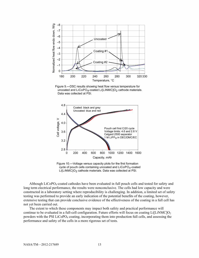
A’s goals for gies that are toexternal shorth no fire or thd an approachn the cathode PO4 coatings e results of difowders that hrent concentraed the exothermaterials. Ththe potential
key to the succtively incorped and LiCoPnominal 1 Ah.1). First cycl coated catho
delivered is quminary test reng term operaaining an unchile cycling atcific capacityhan the uncoa
89
es
inherent safetolerant to elect-circuit, and ihermal runawah to produce s
powders. Thwere applied fferential scanhave been coaations of the crmic peaks suhe use of catho
for thermal rucessful imple
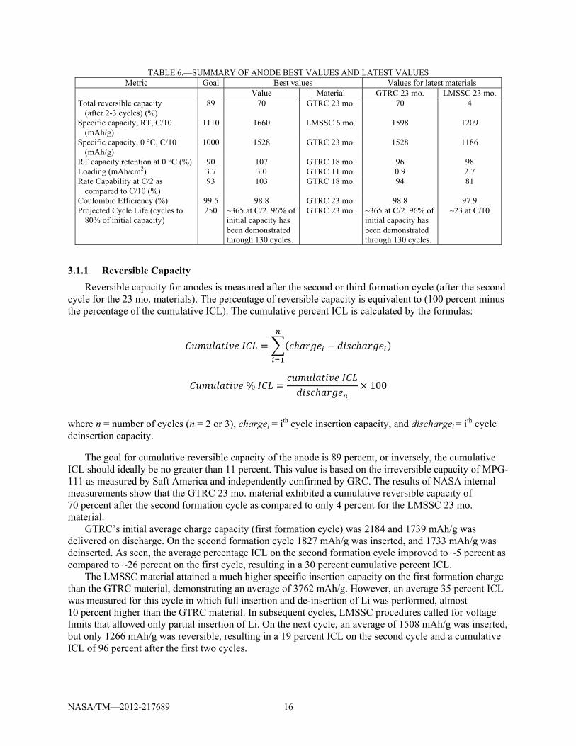
porated into thPO4-coated coh capacity conle formation iodes. Cells weuite similar fosults indicate
ation in cells. coated and a Lt C/10 and ro
y through aboated cathode.
ty in the advactrical and theinternal-shortay. Under consafer electrodeis is discusseto commerci
nning calorimated. The plotcoating to the
uch that much odes that havunaway assoc
ementation of he cell with mommercial Tontaining a cars shown in Fi
ere charged anor all the cells that the LiCoFigure 11 sho
LiCoPO4-coatom temperatuut 20 cycles,
12
anced HE andermal abuse sts (meaning thntract with NAes by utilizingd in more detial Toda 9100
meter testing ots of coated me raw powders
less heat flowe characteristciated with thf a safety comminimal impacoda 9100 Li[Lrbonaceous anigure 10 for twnd dischargeds. oPO4-coated cows the cyclinted commerciure. After formhowever, it e
d UHE cells dsuch as over-the cell designASA, Physicag a lithium cotail in Referen0 Li[LiNMC]Oof the uncoate
materials are ths. As the figuw was generatically less hehe cathode com
mponent into act on the over
LiNMC]O2 canode and the wo cells withd at C/20 betw
cathodes mayng performanial Toda 9100mation, the co
exhibited less
dictate a need temperature, ons pass internal Sciences Inobalt phosphances 2 and 10O2 cathode poed cathode pohe results of t
ure shows, theated as compaeat flow couldmponent in a
a cell is measurall cell perfo
athodes was pbaseline elect
h uncoated catween 4.6 and
y offer performnce of a differ0 Li[LiNMC]oated cathodefade and bett
for cell-levelovercharge, al short circuncorporated (Pate (LiCoPO4)0. owders. Figur
owders and the applicatioe coatings ared to the d greatly redu
full cell. ured by its abormance. Testperformed in ptrolyte (definthodes and tw2.8 V. The
mance benefirent set of pouO2 cathode v
e initially hadter cycling
l
uit PSI) )
re 9
on of
uce or
bility ting pouch
ned in wo
its uch
versus d
NASA/TM
Altho
long termconstructetesting waextensive not yet be
The econtinue tpowders wperforman
M—2012-21768
ough LiCoPO4m electrical per
ed in a laboraas performed testing that c
een carried ouextent to whicto be evaluatewith the PSI Lnce and safety
89
4-coated cathorformance, th
atory setting wto provide an
can provide cout. ch these comped in a full-ceLiCoPO4 coaty of the cells
odes have beehe results werewhere reprodun early indicatonclusive evid
ponents may iell configuratiting, incorporin a more rigo
13
en evaluated ie nonconclusucibility is chation of the podence of the e
impact both saion. Future efrating them inorous set of te
in full pouch ive. The cellsallenging. In
otential benefieffectiveness
afety and prafforts will focunto productionests.
cells and tests had low capaddition, a limits of the coatof the coatin
actical performus on coatingn full cells, an
ted for safety pacity and wermited set of sting, howeverg in a full cel
mance will g Li[LiNMC]Ond assessing t
and re safety r, ll has
O2 the

NASA/TM
3.0 U3.1 A
AdvanLi[LiNMCcarbonaceC/10 and Corporati
GTRCtest condiEC:DEC:Formationanodes corigid, and were deveICL, and mgiven in T
Key mof the pasvalues on parametermaterial. Twere meaeach devereversibleefficiency
M—2012-21768
Ultra HighAnodes
nced anodes aC]O2 cathodeeous anode op0 °C. Anode on (GTRC) aC and LMSSCtions in 2325DMC electron procedures ontain very di
may include eloped througmaximizing c
Table 4 and Tmetrics that arst two years. T
the spider plor achieved ovTable 6 quantsured. In add
eloper. Valuese capacity, spey, and cycle li
89
h Energy C
are required fe, approximateperating at likmaterials disc
and LockheedC materials w-type coin celyte in a 1:1:1were recommfferent siliconother conduc
gh experimentcapacity and c
Table 5, respecre fundamentThe “best” vaot shown in Fer the two yetitatively listsition, it lists ts reported areecific capacityife. The follow
Cell
for the succesely a three tim
ke conditions.cussed in this
d Martin Spacwere independ
ll half cells w1 ratio by vol
mended by then:carbon (Si:Cctive carbon atation with thcycling stabilctively. al to the over
alues demonstFigure 12. Besar developmes the best and the values of ae for the averay, temperaturwing paragrap
14
ss of the UHEmes increase i The goal for
s paper were de Systems Co
dently assessewith a Li meta
ume, and a 20e contractors wC) ratios, bindadditives, uniqe goals of fority. Anode te
rall operation trated for thesst values are dent period. Hegoal values a
all the paramage of four cere performancphs describe t
E cell. When cin specific capr advanced andeveloped at ompany (LMSed at NASA Gal counter elec0 µm thick Twho developeder types thatque formationrmation of a gst procedures
of the anode se parametersdefined as theence, values aand the matereters for the m
ells. The paramce, loading, rathe data for th
coupled with pacity is requ
node materialsGeorgia TechSSC).
GRC using a sctrode, 1.0 Monen Setela sed the materiat range from en procedures good SEI layes from GTRC
have measurs are comparee highest valuare not necessrials from whimost recent dmeters shownate capabilityhese paramete
a fully succesuired over a Ss is 1000 mAhh Research
standard set oM LiPF6 in separator. als. Since theelastomeric tofor each mate
er, minimizinC and LMSSC
ed over the coed to the goal ue of the partisarily for the ich the best v
deliverables frn include , coulombic ers in more de
ssful SOA h/g at
of
e o erial g
C are
ourse
icular same
values rom
etail.

NASA/TM
Test 23 °C chara
0 °C charact
aDeliverables
Test Formation
23 °C chara
0 °C charact
aDeliverable 4
M—2012-21768
stage acterization A
Cterization A
taP
s 3 and 4
stage PD2V
acterization AC
terization AtaP
4
89
TABL
At 23 °C, charge C/10 to 1.0 V. PeAll charges are paper to C/50. So
Perform for 10 cy
TABL
Perform at 23 °CDe-insert to 0.9 V2nd cycle: Insert V. Rest for 5 minAt 23 °C, charge C/10 to 0.9 V. PeAll charges are paper to C/50. So
Perform for 10 cy
LE 4.—GTRC A
at C/10 to 10 merform for 10 cycerformed at 23 °ak for 2 hr after ycles.
LE 5.—LMSSC
. 1st cycle: InserV. at C/8 to 150 m
n after each compat C/10 to 150 m
erform for 10 cycerformed at 23 °ak for 2 hr after ycles.
15
ANODE TEST PTest c
mV, hold voltage,cles. Rest for 5 m°C. Charge at C/all temperature
ANODE TEST Test c
rt at C/20 to 25 m
V, hold voltage plete insertion anmV, hold voltagecles. Rest for 5 °C. Charge at C/all temperature
PROCEDURESa
conditions , and allow curremin after each ch/10 to 10 mV, hochanges. At 0 °C
PROCEDURESconditions mV, hold voltag
and allow currenand de-insertion.e, and allow curmin after each c
/10 to 150 mV, hchanges. At 0 °C
a
ent to taper to C/harge and dischaold voltage, and C, discharge at C
Sa
ge and allow curr
nt to taper to C/5
rrent to taper to Ccharge and dischhold voltage, andC, discharge at C
/50. Discharge aarge. allow current to
C/10 to 1.0 V.
rent to taper to C
50. De-insert to
C/50. Discharge harge. d allow current tC/10 to 0.9 V.
at
o
C/50.
0.9
at
to
NASA/TM—2012-217689 16
TABLE 6.—SUMMARY OF ANODE BEST VALUES AND LATEST VALUES Metric Goal Best values Values for latest materials
Value Material GTRC 23 mo. LMSSC 23 mo. Total reversible capacity
(after 2-3 cycles) (%) 89 70 GTRC 23 mo. 70 4
Specific capacity, RT, C/10 (mAh/g)
1110 1660 LMSSC 6 mo. 1598 1209
Specific capacity, 0 °C, C/10 (mAh/g)
1000 1528 GTRC 23 mo. 1528 1186
RT capacity retention at 0 °C (%) 90 107 GTRC 18 mo. 96 98 Loading (mAh/cm2) 3.7 3.0 GTRC 11 mo. 0.9 2.7 Rate Capability at C/2 as
compared to C/10 (%) 93 103 GTRC 18 mo. 94 81
Coulombic Efficiency (%) 99.5 98.8 GTRC 23 mo. 98.8 97.9 Projected Cycle Life (cycles to
80% of initial capacity) 250 ~365 at C/2. 96% of
initial capacity has been demonstrated through 130 cycles.
GTRC 23 mo. ~365 at C/2. 96% of initial capacity has been demonstrated through 130 cycles.
~23 at C/10
3.1.1 Reversible Capacity Reversible capacity for anodes is measured after the second or third formation cycle (after the second
cycle for the 23 mo. materials). The percentage of reversible capacity is equivalent to (100 percent minus the percentage of the cumulative ICL). The cumulative percent ICL is calculated by the formulas:
%
100
where n = number of cycles (n = 2 or 3), chargei = ith cycle insertion capacity, and dischargei = ith cycle deinsertion capacity.
The goal for cumulative reversible capacity of the anode is 89 percent, or inversely, the cumulative ICL should ideally be no greater than 11 percent. This value is based on the irreversible capacity of MPG-111 as measured by Saft America and independently confirmed by GRC. The results of NASA internal measurements show that the GTRC 23 mo. material exhibited a cumulative reversible capacity of 70 percent after the second formation cycle as compared to only 4 percent for the LMSSC 23 mo. material.
GTRC’s initial average charge capacity (first formation cycle) was 2184 and 1739 mAh/g was delivered on discharge. On the second formation cycle 1827 mAh/g was inserted, and 1733 mAh/g was deinserted. As seen, the average percentage ICL on the second formation cycle improved to ~5 percent as compared to ~26 percent on the first cycle, resulting in a 30 percent cumulative percent ICL.
The LMSSC material attained a much higher specific insertion capacity on the first formation charge than the GTRC material, demonstrating an average of 3762 mAh/g. However, an average 35 percent ICL was measured for this cycle in which full insertion and de-insertion of Li was performed, almost 10 percent higher than the GTRC material. In subsequent cycles, LMSSC procedures called for voltage limits that allowed only partial insertion of Li. On the next cycle, an average of 1508 mAh/g was inserted, but only 1266 mAh/g was reversible, resulting in a 19 percent ICL on the second cycle and a cumulative ICL of 96 percent after the first two cycles.

NASA/TM
The e
capacity lof the amocrystallinecycling beto higher within theThis cyclicapacity ocathode caof the cath
3.1.2 SSpeci
measured respectiveformationcharacteriat 0 °C is
LMSSSpecific cgoal value
M—2012-21768
extremely highoss, but ratheorphous range phase. LMSetween the twfade, as was ie specified voing method prof the Si anodapacity must hode in the ce
pecific Capafic capacity abetween the
e temperaturen. For anodes,ization is perfreported for d
SC 6 mo. matcapacity mease of 1110 mA
89
h irreversibleer is induced be of Si (below
SSC’s internalwo phases (aminitially repor
oltage limits arecludes the m
de must still bbe matched t
ell as well, ev
acity at 23 and 0 °Cvoltage limit. Specific cap characterizat
formed on to discharge at 0terial demonssured at 23 °C
Ah/g. Howeve
capacity of tby the cyclingw 50 mV) andl studies show
morphous and rted by Obrovas given in Tamaterials’ prabe carried ando the initial S
ven after the I
C are plotted as specified fopacity at both tion at 0 °C isavoid any cap0 °C after a 23strated the besC and C/10 oner, the materia
17
the LMSSC ang procedures ad into the rangwed that for thcrystalline) a
vac and Krausable 5 is still pactical applica
contributes tSi capacity, wCL of the cat
as a percentagor each materi
23 and 0 °Cs performed opacity fade in3 °C charge. st specific capn this materialal had high IC
node beyond adopted by Lge in which Sheir material adversely impse (Ref. 11). Hpoor on these ation in a lighto the mass of
which thereby thode is accou
ge of the special (see Tableis reported fo
on a different ntroduced by p
pacity of all ol is 1660 mAh
CL and poor r
the first cyclLMSSC to avoSi is convertedcomposition,
pacted cyclingHowever, cycmaterials, as
htweight cell, f the cell. In aincreases the
unted for.
cific capacity e 4 and Table or the first cycset of cells th
prior cycling.
of the developh/g, which farrate capability
e is not a trueoid cycling oud into its , continuous g stability andcling stability seen in Figursince the unu
addition, the e mass contrib
goals at C/105) and at the cle following han the 23 °C. Specific cap
pmental materr exceeded th
y. The GTRC
e utside
d led y re 13.
usable
bution
0 as
C pacity
rials. he
NASA/TM—2012-217689 18
23 mo. material was a close second, achieving 1598 mAh/g. At 0 °C and C/10, 1528 mAh/g was obtained on the same material, which also far exceeded the 1000 mAh/g goal value. While this material exhibited excellent capacity retention at 0 °C, rate capability, and cycling stability, coulombic efficiency, ICL, and loading still need improvement. Project goals were established for 0 °C operation. Room temperature (RT) goals were calculated as the expected minimum specific capacity, based on the desire to retain at least 90 percent of RT capacity when operating at 0 °C.
3.1.3 Temperature Performance Temperature performance is measured as the percentage of RT capacity retained at 0 °C. A goal of
90 percent was established for temperature performance based on what is reasonably practical given current SOA Li-ion cell performance. With the exception of the first set of deliverables from both contracts, all subsequent materials have demonstrated excellent temperature performance. The best values column in Table 6 indicates a value of 107 percent for the percentage of RT capacity retained at 0 °C since the capacity of the GTRC 23 mo. material tends to improve with cycling.
3.1.4 Loading Loading is a measure of capacity per unit area. The target loading for the NASA anodes is
~3.7 mAh/cm2. Currently the LMSSC and GTRC anodes have very low loading as compared to that found in practical cells that are designed to offer high capacity at moderate discharge rates. Low loading will necessitate larger electrode area to provide the equivalent capacity as electrodes with higher loading, which adversely impacts energy density. Specific energy will also suffer, as larger areas of current collector and possibly larger cell housings (i.e., inactive components) will be needed to accommodate impractically sized electrodes. Through our studies, trends showed that higher loaded anodes tended to have lower coulombic efficiency and cycle life. This is an area for further study and optimization.
3.1.5 Rate Capability Rate capability testing is performed at C/5 and C/2 and compared to specific capacity achieved at
C/10. A target of 93 percent of the C/10 performance was established for C/2 performance. The Si:C-based anodes have demonstrated excellent rate capability. The rate capability for recent deliverables has consistently measured between 94 and >100 percent (the specific capacity of the GTRC 23 mo. material improved with cycling).
3.1.6 Cycle Life Cycle life assessments are performed at 23 °C in half-cells vs. Li/Li+. The goal for the UHE cell is
200 cycles at 100 percent DoD to 80 percent of initial capacity when cycled at C/2. To attain 200 cycles on the cell level, 250 cycles is desired from the components. Cycle life of the LMSSC material is assessed at C/10 due to the high fade observed in early cycling. Figure 13 shows results of cycle life testing for GTRC and LMSSC 23 mo. materials. Here, initial capacity is defined as the capacity delivered on the first discharge of continuous cycling (cycle 10 for the LMSSC material and cycle 16 for the GTRC material). The LMSSC material displays poor cycling stability, achieving only 23 cycles to our defined point of failure. Further, it only achieves 37 cycles prior to its specific capacity falling below the anode threshold value of 600 mAh/g, the minimum success criteria. The GTRC material demonstrated >45 cycles with virtually no fade, and as previously discussed, the specific capacity tended to improve with cycling. Ninety-six percent of the initial capacity is measured after 130 cycles. Cycling on this material is still in progress. Using a linear extrapolation based on the rate of fade, approximately 365 cycles are projected to 80 percent of the initial capacity.
In order to improve cycling stability of the Si-based anodes, <10 percent by weight of VC was added to the baseline electrolyte in both GTRC and LMSSC cells. While a beneficial effect on cycling stability was seen in the GTRC material, the performance of the LMSSC material did not improve with the addition of VC.

NASA/TM
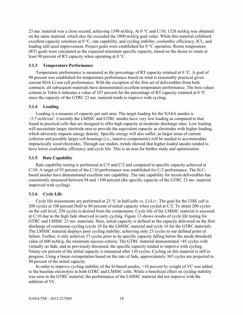
3.1.7 DFigur
above for to a singleanode maperformancoulombic
M—2012-21768
Discussion e 14 and Figu6, 11, 18, and
e material. NAaterials when pnce, rate capac efficiency, a
89
ure 15 containd 23 mo. matASA has demperformance
ability and cycand loading r
n spider plots terials from G
monstrated excis measured bcling stabilityemain as chal
19
that show theGTRC and LMcellent performbased on specy metrics. Forllenges to be
e progressionMSSC. Values
mance with thcific capacityr the GTRC maddressed fur
n of the params plotted in eahese NRA-deat 23 and 0 °
materials, imprther.
meters discussach graph pereveloped Si-b°C, temperatuprovements to
ed rtain based ure o IC,
NASA/TM
As dis
would reqlarge masanode wa
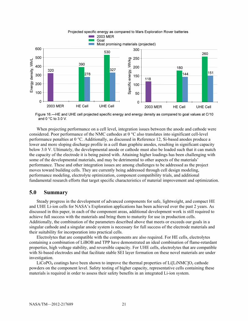
4.0 CCell-l
materials Projected the most pthe projecRover batproject us
M—2012-21768
scussed in thequire the use os penalties. Us eliminated f
Cell Projeclevel specific that provide tvalues for ce
promising macted values artteries is also ses as a baseli
89
e section on rof cycling reg
Upon modelinfrom further c
ctions energy and ethe best comb
ell level specifaterials’ perfoe shown in Fiincluded for
ine to measure
eversible capgimes that limng its practicalconsideration
energy densitybination of higfic energy and
ormance at C/igure 16. Perfcomparison. Te progress.
20
acity, the incomit the useable
l application i in the UHE c
y values are pgh specific cad energy dens10 to 3.0 V anformance of LThese cells co
orporation ofe capacity in tin an integratcell.
predicted usinapacity and hsity are basednd 0 °C (Ref.Li-ion cells frontain the che
f the LMSSC the cell, thereted cell design
ng the cathodeigh capacity r
d on projectiof. 12). The goarom the 2003 emistry that th
anode in a ceeby resulting n, the LMSSC
e and anode retention to d
ons using dataal values versMars Explorhis developm
ell in C
date. a for sus ation
ment
NASA/TM
When
considereperformanlower andbelow 3.0the capacisome of thperformanmoves towperformanfundamen
5.0 SStead
and UHE discussed achieve fuAdditionasingular ctheir suita
Electrcontainingpropertieswith Si-bainvestigat
LiCoPpowders omaterials
M—2012-21768
n projecting pd. Poor perfonce penalties d more sloping0 V. Ultimatelity of the eleche developmence. These anward buildingnce modelingntal research e
Summary dy progress in
Li-ion cells fin this paper
ull success wially, the combcathode and a ability for incorolytes that arg a combinatis, high voltagased electrodetion. PO4 coatings on the compois required in
89
erformance ormance of theat 0 °C. Addig discharge ply, the develoctrode it is beiental materialnd other integrg cells. They a, electrolyte o
efforts that tar
the developmfor NASA’s E, in each of thith the materibination of thesingular anod
orporation intre compatibleion of LiBOBe stability, anes and that fa
have been shnent level. Sa
n order to asse
on a cell levele NMC cathoitionally, as d
profile in a celopmental anoding paired wils, and may beration issues aare currently boptimization, rget specific c
ment of advanExploration aphe componentals and bring e parameters de system is nto practical ce
e with the comB and TPP havnd reversible ccilitate stable
hown to improafety testing oess their safet
21
, integration iodes at 0 °C aldiscussed in Rll than graphide or cathode th. Attaining e detrimental are among chbeing addresscomponent c
characteristic
nced componepplications hat areas, additithem to matudescribed abonecessary for ells.
mponents are ave demonstratcapacity. For e SEI layer for
ove the thermof higher capaty benefits in
issues betweelso translates
Reference 12, ite anodes, res must also behigher loadinto other aspe
hallenges to bsed through ccompatibility s of material
ents for safe, as been achieional developurity for use iove that meetfull success o
also requiredated an ideal c
UHE cells, ermation on th
mal properties acity, represenan integrated
en the anode ainto significaSi-based ano
sulting in signe loaded such ngs has been cects of the mabe addressed acell design motrials, and adimprovement
lightweight, aved over the
pment work isin production ts or exceeds of the electro
d. For HE cellcombination oelectrolytes thhese novel ma
of Li[LiNMCntative cells c
d Li-ion system
and cathode want cell-level
odes produce anificant capacthat it can machallenging w
aterials’ as the project odeling,
dditional t and optimiz
and compact past 2 years.
s still requiredcells. our goals in ade materials a
s, electrolytesof flame-retarhat are compataterials are un
C]O2 cathodecontaining them.
were
a city atch with
zation.
HE As
d to
a and
s rdant tible
nder
ese


NASA/TM—2012-217689 23
Appendix—Nomenclature
°C degrees Celsius C carbon DEC diethyl carbonate DMC dimethyl carbonate DMMP dimethyl methyl phosphonate DoD depth-of-discharge EC ethylene carbonate EMC ethyl methyl carbonate g/cc grams per cubic centimeter GRC Glenn Research Center GTRC Georgia Tech Research Corporation HE High Energy ICL irreversible capacity loss JPL Jet Propulsion Laboratory JSC Johnson Space Center KPP key performance parameters LiBOB lithium bis(oxalato) borate LiCoPO4 lithium cobalt phosphate Li-ion lithium-ion LiPF6 lithium hexafluorophosphate LMSSC Lockheed Martin Space Systems Company Li[LiNMC]O2 lithium nickel manganese cobalt oxide M molar mAh/g milliampere-hours per gram MCMB mesocarbon microbeads MER Mars Exploration Rovers mo. month(s) mV millivolts NASA National Aeronautics and Space Administration NEI NEI Corporation PSI Physical Sciences, Incorporated RT room temperature SEI solid electrolyte interface SET self-extinguishing time Si silicon Si:C silicon:carbon SOA state-of-the-art TD tap density

NASA/TM—2012-217689 24
TPP triphenyl phosphate UHE Ultra High Energy µm micrometer UTA University of Texas at Austin V volts VC vinylene carbonate Wh/kg watt-hours per kilogram Wh/L watt-hours per liter YTP/URI Yardney Technical Products/University of Rhode Island
NASA/TM—2012-217689 25
References 1. C.M. Reid and W.R. Bennett, “A Study on Advanced Lithium-Based Battery Cell Chemistries to
Enhance Lunar Exploration Missions,” National Aeronautics and Space Administration Glenn Research Center, Cleveland, OH, NASA/TM—2010-216791, September 2010.
2. C.M. Reid, “Progress in Materials and Component Development for Advanced Lithium-ion Cells for NASA’s Exploration Missions,” National Aeronautics and Space Administration Glenn Research Center, Cleveland, OH, NASA/TM—2011-217209, September 2011.
3. A. Manthiram, High-energy density cathodes for next generation lithium-ion batteries, Final Report to NASA Glenn Research Center from The University of Texas at Austin for contract NNC09CA08C, March 2011.
4. N.M. Hagh, F. Badway, M. Moorthi, G. Skandan, W. West, R. Bugga, C. Reid, Improvements in Energy Density and Stability of Advanced Cathode Materials for NASA’s Applications, NASA Aerospace Battery Workshop, November 16-18, 2010.
5. J. Li, R. Klopsch, M.C. Stan, S. Nowak, M. Kunze, M. Winter, and S. Passerini, Synthesis and electrochemical performance of the high voltage cathode material Li[Li0.2Mn0.56Ni0.16Co0.08]O2 with improved rate capability, J. Power Sources, 196 (2011) 4821-4825.
6. N.M. Hagh, F. Badway, K. Martin, M. Moorthi, and G. Skandan, High Energy Density Cathode Materials for Li-Ion Battery Applications, 44th Power Sources Conference, Las Vegas, NV, June 14-17, 2010.
7. N.M. Hagh, G.G. Amatucci, A new solid-state process for synthesis of LiMn1.5Ni0.5O4−δ spinel, J. Power Sources, 195 (2010) 5005-5012.
8. J.M. Zheng, X.B. Wu, and Y. Yang, A comparison of preparation method on the electrochemical performance of cathode material Li[Li0.2Mn0.54Ni0.13Co0.13]O2 for lithium ion battery, Electrochimica Acta 56 (2011) 3071-3078.
9. M.C. Smart, F.C. Krause, W.C. West, J. Soler, L. Whitcanack, and R.V. Bugga, “Development of Electrolytes With Improved Safety Characteristics,” Final FY10 Report for the NASA Exploration Technology Development Program Energy Storage Project, September, 2010.
10. C.M. Lang, A. Newman, K. Constantine, and J. Ma, Improved Cathode Material Safety via a Metal Phosphate Coating, NASA Aerospace Battery Workshop, Huntsville, AL, November, 2009.
11. M.N. Obrovac and L.J. Krause, Reversible Cycling of Crystalline Silicon Powder, J. Electrochem. Soc. 154 (2007) A103-A108.
12. W.R. Bennett, “Forecasts for Hypothetical Li-Ion Cells Using FY2010 Data for ETDP Electrodes,” National Aeronautics and Space Administration Glenn Research Center, Cleveland, OH, NASA/TM—2011-TBD, 2011 (to be published).
13. R. Staniewicz, personal communication, September 2011. 14. J. Liu, Q. Wang, B. Reeja-Jayan, and A. Manthiram, Carbon-coated high capacity layered
Li[Li0.2Mn0.54Ni0.13Co0.13]O2 cathodes, Electrochemistry Communications, 12 (2010) 750-753.

REPORT DOCUMENTATION PAGE Form Approved
OMB No. 0704-0188 The public reporting burden for this collection of information is estimated to average 1 hour per response, including the time for reviewing instructions, searching existing data sources, gathering and maintaining the data needed, and completing and reviewing the collection of information. Send comments regarding this burden estimate or any other aspect of this collection of information, including suggestions for reducing this burden, to Department of Defense, Washington Headquarters Services, Directorate for Information Operations and Reports (0704-0188), 1215 Jefferson Davis Highway, Suite 1204, Arlington, VA 22202-4302. Respondents should be aware that notwithstanding any other provision of law, no person shall be subject to any penalty for failing to comply with a collection of information if it does not display a currently valid OMB control number. PLEASE DO NOT RETURN YOUR FORM TO THE ABOVE ADDRESS.
1. REPORT DATE (DD-MM-YYYY) 01-09-2012
2. REPORT TYPE Technical Memorandum
3. DATES COVERED (From - To)
4. TITLE AND SUBTITLE Advanced Materials and Component Development for Lithium-Ion Cells for NASA Missions
5a. CONTRACT NUMBER
5b. GRANT NUMBER
5c. PROGRAM ELEMENT NUMBER
6. AUTHOR(S) Reid, Concha, M.
5d. PROJECT NUMBER
5e. TASK NUMBER
5f. WORK UNIT NUMBER WBS 152964.04.01.01.01.03
7. PERFORMING ORGANIZATION NAME(S) AND ADDRESS(ES) National Aeronautics and Space Administration John H. Glenn Research Center at Lewis Field Cleveland, Ohio 44135-3191
8. PERFORMING ORGANIZATION REPORT NUMBER E-18372
9. SPONSORING/MONITORING AGENCY NAME(S) AND ADDRESS(ES) National Aeronautics and Space Administration Washington, DC 20546-0001
10. SPONSORING/MONITOR'S ACRONYM(S) NASA
11. SPONSORING/MONITORING REPORT NUMBER NASA/TM-2012-217689
12. DISTRIBUTION/AVAILABILITY STATEMENT Unclassified-Unlimited Subject Categories: 15, 20, and 44 Available electronically at http://www.sti.nasa.gov This publication is available from the NASA Center for AeroSpace Information, 443-757-5802
13. SUPPLEMENTARY NOTES
14. ABSTRACT Human missions to Near Earth Objects, such as asteroids, planets, moons, liberation points, and orbiting structures, will require safe, high specific energy, high energy density batteries to provide new or extended capabilities than are possible with today’s state-of-the-art aerospace batteries. The Enabling Technology Development and Demonstration Program, High Efficiency Space Power Systems Project battery development effort at the National Aeronautics and Space Administration (NASA) is continuing advanced lithium-ion cell development efforts begun under the Exploration Technology Development Program Energy Storage Project. Advanced, high-performing materials are required to provide improved performance at the component-level that contributes to performance at the integrated cell level in order to meet the performance goals for NASA’s High Energy and Ultra High Energy cells. NASA’s overall approach to advanced cell development and interim progress on materials performance for the High Energy and Ultra High Energy cells after approximately 1 year of development has been summarized in a previous paper. This paper will provide an update on these materials through the completion of 2 years of development. The progress of materials development, remaining challenges, and an outlook for the future of these materials in near term cell products will be discussed. 15. SUBJECT TERMS Lithium batteries; Storage batteries; Electric batteries; Electrochemical cells; Energy storage; Space missions; Spacecraft power supplies; Electric power supplies 16. SECURITY CLASSIFICATION OF: 17. LIMITATION OF
ABSTRACT UU
18. NUMBER OF PAGES
32
19a. NAME OF RESPONSIBLE PERSON STI Help Desk (email:[email protected])
a. REPORT U
b. ABSTRACT U
c. THIS PAGE U
19b. TELEPHONE NUMBER (include area code) 443-757-5802
Standard Form 298 (Rev. 8-98)Prescribed by ANSI Std. Z39-18