Embed Size (px)
Citation preview
Advanced Manufacturing Innovation Initiative:
“Technology Developments in Manufacturing of Large Composite Wind Turbine Blades “ Presented to Attendees of:
University of Massachusetts Lowell
Wind Energy Research Workshop Stephen C. Nolet Principal Engineer / Director of Innovation
TPI Composites, Inc.
September 22, 2011
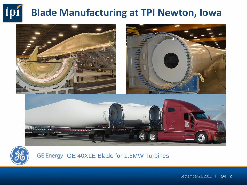
Blade Manufacturing at TPI Newton, Iowa
GE 40XLE Blade for 1.6MW Turbines
September 22, 2011 | Page 2
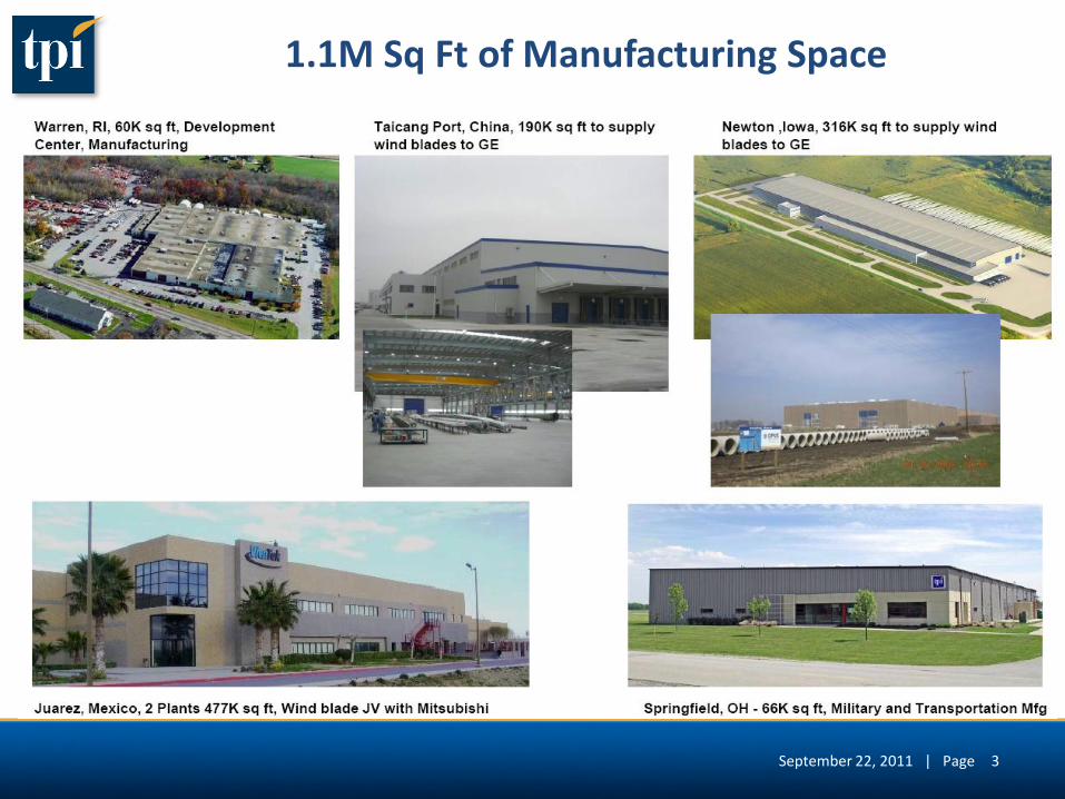
1.1M Sq Ft of Manufacturing Space
3 September 22, 2011 | Page
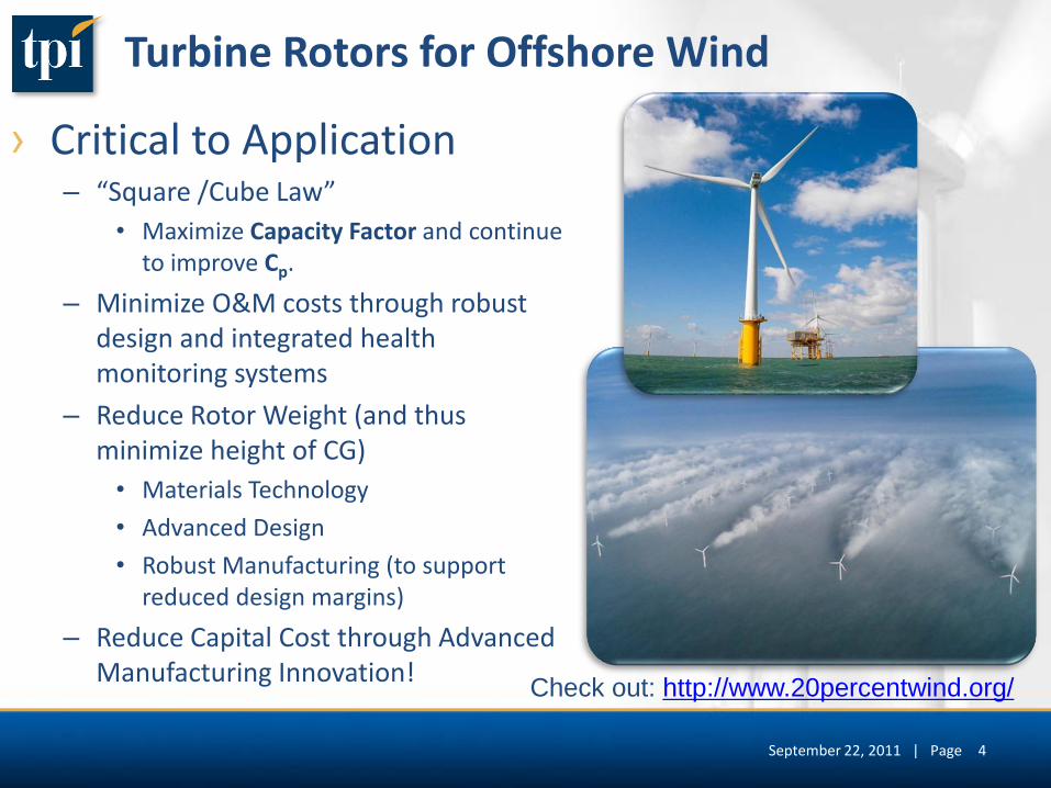
Turbine Rotors for Offshore Wind
› Critical to Application – “Square /Cube Law”
• Maximize Capacity Factor and continue to improve Cp.
– Minimize O&M costs through robust design and integrated health monitoring systems
– Reduce Rotor Weight (and thus minimize height of CG)
• Materials Technology
• Advanced Design
• Robust Manufacturing (to support reduced design margins)
– Reduce Capital Cost through Advanced Manufacturing Innovation!
4
Check out: http://www.20percentwind.org/
September 22, 2011 | Page
5
Advanced Manufacturing Innovation Initiative
September 22, 2011 | Page
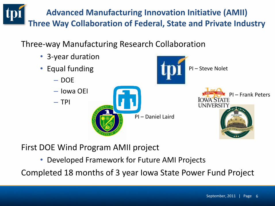
Advanced Manufacturing Innovation Initiative (AMII) Three Way Collaboration of Federal, State and Private Industry
Three-way Manufacturing Research Collaboration
• 3-year duration
• Equal funding
– DOE
– Iowa OEI
– TPI
First DOE Wind Program AMII project
• Developed Framework for Future AMI Projects
Completed 18 months of 3 year Iowa State Power Fund Project
PI – Daniel Laird
PI – Frank Peters
PI – Steve Nolet
September, 2011 | Page 6
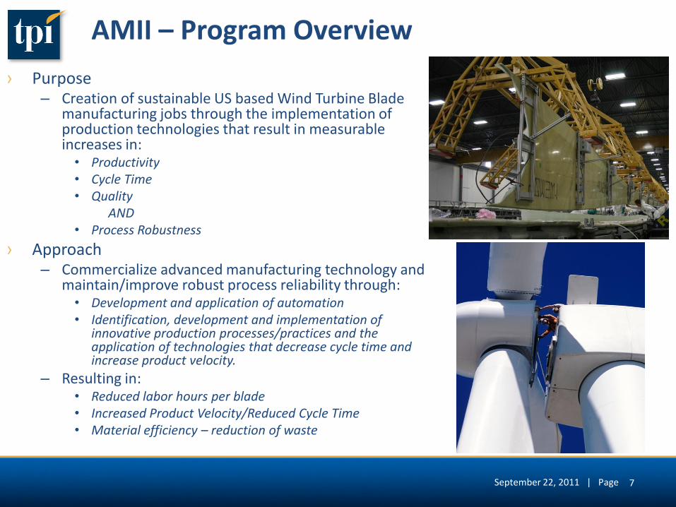
AMII – Program Overview
› Purpose – Creation of sustainable US based Wind Turbine Blade
manufacturing jobs through the implementation of production technologies that result in measurable increases in:
• Productivity • Cycle Time • Quality
AND • Process Robustness
› Approach – Commercialize advanced manufacturing technology and
maintain/improve robust process reliability through: • Development and application of automation • Identification, development and implementation of
innovative production processes/practices and the application of technologies that decrease cycle time and increase product velocity.
– Resulting in: • Reduced labor hours per blade • Increased Product Velocity/Reduced Cycle Time • Material efficiency – reduction of waste
September 22, 2011 | Page 7
AMII – Program Overview (cont.)
› Strategy – A coherent set of on-going activities in the form of AMII “Projects” that
are determined by the steering committee. • Projects are brought to the committee in the form of “Project White Papers”
submitted by any one of the members of the Program Organizations (i.e., TPI, SNL, and ISU).
• Projects that gain approval through the steering committee will be expanded to Project Proposals to detail resource requirements and schedule.
• Project Proposals gain project funding after review by the AMII Oversight Committee.
› Goals – Measurable benchmarks based on Engineering Value Analysis upon
Project Completion • Improve Labor Productivity by 35%..
• Reduce the cycle time by 35%.
• Improve reliability while maintaining cost.
September 22, 2011 | Page 8

Blade Manufacturing
August 10, 2010 | Page 9
AMII Program Overview: Major Production Focus Areas
› Factory Modeling – Factory Modeling
– 3-D Factory Modeling/Work Cell Modeling
› Non-destructive Inspection
› Advanced Modular Automation
› Mold Operations – Kitting
– Material Transfer
– Layup
– Processing
– Assembly
› Finishing
September 22, 2011 | Page 10
11
AMII Projects
September 22, 2011 | Page
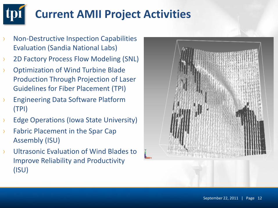
Current AMII Project Activities
› Non-Destructive Inspection Capabilities Evaluation (Sandia National Labs)
› 2D Factory Process Flow Modeling (SNL)
› Optimization of Wind Turbine Blade Production Through Projection of Laser Guidelines for Fiber Placement (TPI)
› Engineering Data Software Platform (TPI)
› Edge Operations (Iowa State University)
› Fabric Placement in the Spar Cap Assembly (ISU)
› Ultrasonic Evaluation of Wind Blades to Improve Reliability and Productivity (ISU)
12 September 22, 2011 | Page
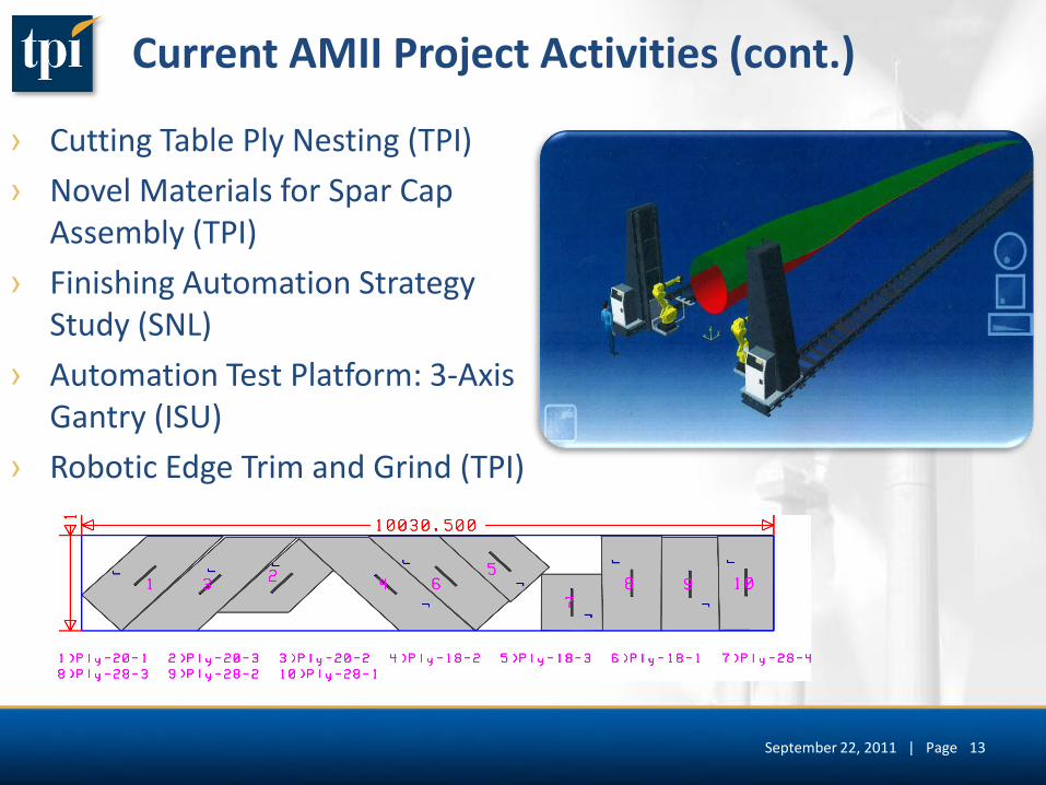
Current AMII Project Activities (cont.)
› Cutting Table Ply Nesting (TPI)
› Novel Materials for Spar Cap Assembly (TPI)
› Finishing Automation Strategy Study (SNL)
› Automation Test Platform: 3-Axis Gantry (ISU)
› Robotic Edge Trim and Grind (TPI)
13 September 22, 2011 | Page
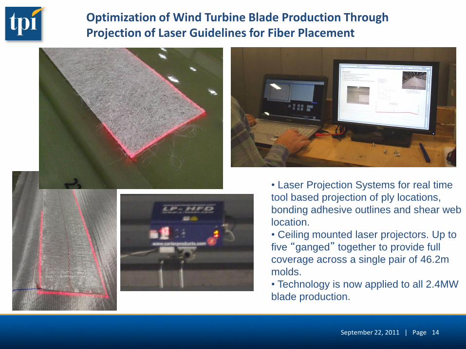
Optimization of Wind Turbine Blade Production Through Projection of Laser Guidelines for Fiber Placement
• Laser Projection Systems for real time
tool based projection of ply locations,
bonding adhesive outlines and shear web
location.
• Ceiling mounted laser projectors. Up to
five “ganged” together to provide full
coverage across a single pair of 46.2m
molds.
• Technology is now applied to all 2.4MW
blade production.
14 September 22, 2011 | Page
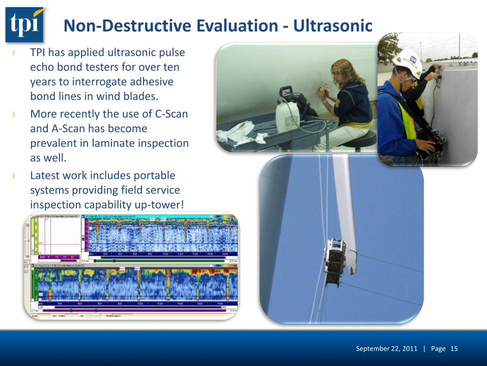
Non-Destructive Evaluation - Ultrasonic
› TPI has applied ultrasonic pulse echo bond testers for over ten years to interrogate adhesive bond lines in wind blades.
› More recently the use of C-Scan and A-Scan has become prevalent in laminate inspection as well.
› Latest work includes portable systems providing field service inspection capability up-tower!
September 22, 2011 | Page 15
7-7-10
2 PLIES OF DOUBLE BIAS (DB)(+45, +45)_ _
2 PLIES OF DOUBLE BIAS (DB)(+45, +45)_ _
30.00"
1.75" (45mm) UNIAXIAL (SPANWISE)
18.00"
2.00" DIA
1.50" DIA
1.00" DIA
.50" DIA
.50" DIA
1.00" DIA
1.50" DIA
2.00" DIA
2.00" DIA
.50" DIA
1.00" DIA
1.50" DIA
1.50" DIA
1.00" DIA
.50" DIA
2.00" DIA
2.00" DIA
.50" DIA
1.00" DIA
1.50" DIA
1.50" DIA
1.00" DIA
.50" DIA
2.00" DIA
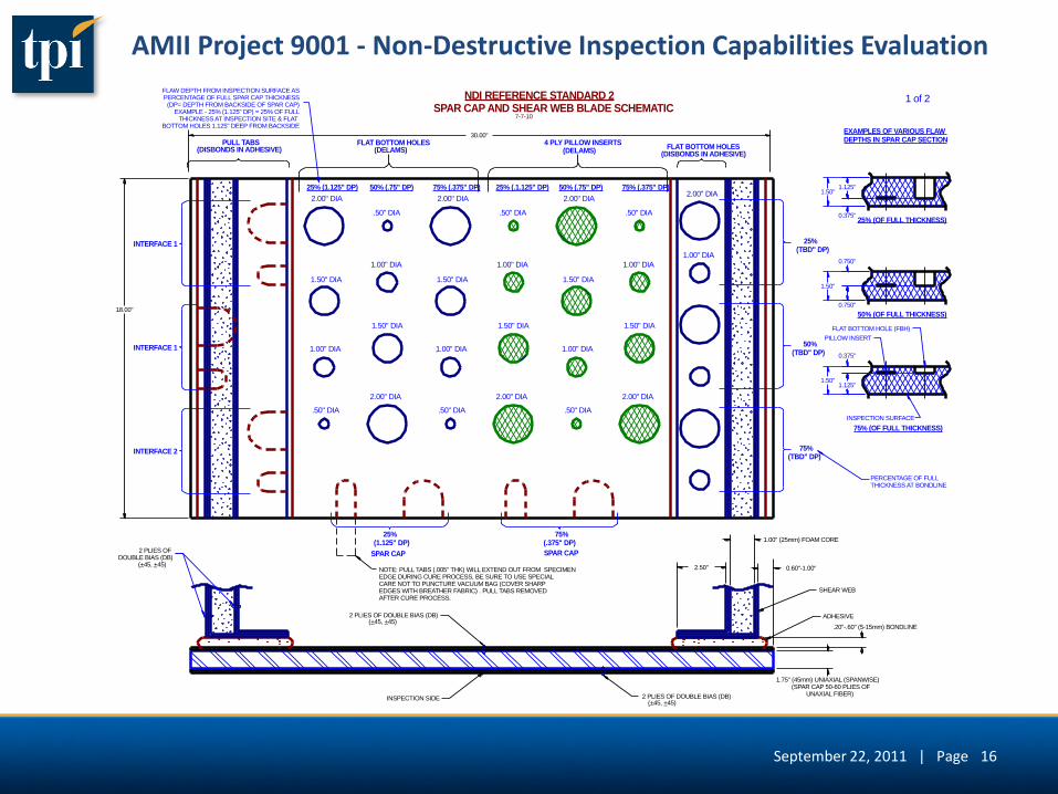
25% (1.125" DP) 50% (.75" DP) 75% (.375" DP) 25% (.1.125" DP) 50% (.75" DP) 75% (.375" DP)
FLAT BOTTOM HOLES 4 PLY PILLOW INSERTS
25%(TBD" DP)
25%(1.125" DP)
75%(.375" DP)
INTERFACE 1
INTERFACE 1
INTERFACE 2
2 PLIES OF DOUBLE BIAS (DB)
(+45, +45)_
1.00" (25mm) FOAM CORE
0.60"-1.00"
1 of 2
FLAT BOTTOM HOLES
ADHESIVE
SHEAR WEB
2.00" DIA
1.00" DIA
(SPAR CAP 50-60 PLIES OFUNAXIAL FIBER)
50%(TBD" DP)
75%(TBD" DP)
(DISBONDS IN ADHESIVE)(DELAMS)(DELAMS)PULL TABS
(DISBONDS IN ADHESIVE)
NDI REFERENCE STANDARD 2SPAR CAP AND SHEAR WEB BLADE SCHEMATIC
INSPECTION SURFACE
EXAMPLES OF VARIOUS FLAW DEPTHS IN SPAR CAP SECTION
1.50"
0.375"
0.750"
1.125"
1.50"
1.50"
1.125"
0.750"
0.375"
FLAW DEPTH FROM INSPECTION SURFACE ASPERCENTAGE OF FULL SPAR CAP THICKNESS
(DP= DEPTH FROM BACKSIDE OF SPAR CAP)EXAMPLE - 25% (1.125" DP) = 25% OF FULL
THICKNESS AT INSPECTION SITE & FLAT BOTTOM HOLES 1.125" DEEP FROM BACKSIDE
PILLOW INSERT
FLAT BOTTOM HOLE (FBH)
75% (OF FULL THICKNESS)
50% (OF FULL THICKNESS)
25% (OF FULL THICKNESS)
PERCENTAGE OF FULLTHICKNESS AT BONDLINE
NOTE: PULL TABS (.005" THK) WILL EXTEND OUT FROM SPECIMENEDGE DURING CURE PROCESS, BE SURE TO USE SPECIALCARE NOT TO PUNCTURE VACUUM BAG (COVER SHARPEDGES WITH BREATHER FABRIC) . PULL TABS REMOVED AFTER CURE PROCESS.
SPAR CAP SPAR CAP
_
INSPECTION SIDE
2.50"
.20"-.60" (5-15mm) BONDLINE
AMII Project 9001 - Non-Destructive Inspection Capabilities Evaluation
16 September 22, 2011 | Page
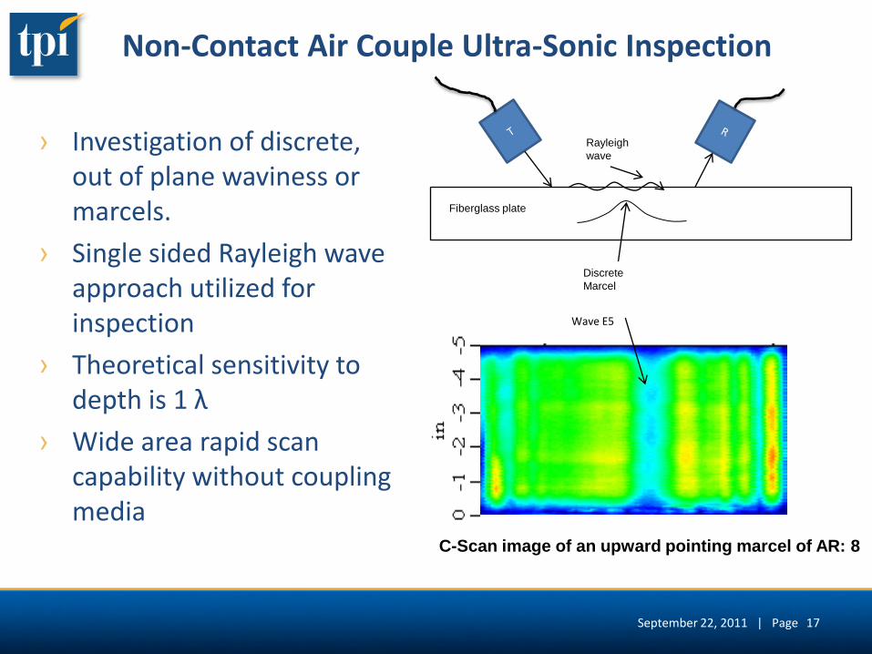
Non-Contact Air Couple Ultra-Sonic Inspection
› Investigation of discrete, out of plane waviness or marcels.
› Single sided Rayleigh wave approach utilized for inspection
› Theoretical sensitivity to depth is 1 λ
› Wide area rapid scan capability without coupling media
Fiberglass plate
Discrete
Marcel
Rayleigh
wave
Wave E5
C-Scan image of an upward pointing marcel of AR: 8
September 22, 2011 | Page 17
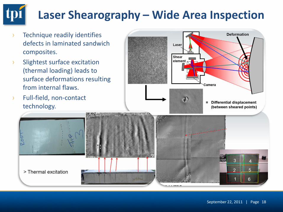
Laser Shearography – Wide Area Inspection
› Technique readily identifies defects in laminated sandwich composites.
› Slightest surface excitation (thermal loading) leads to surface deformations resulting from internal flaws.
› Full-field, non-contact technology.
September 22, 2011 | Page 18
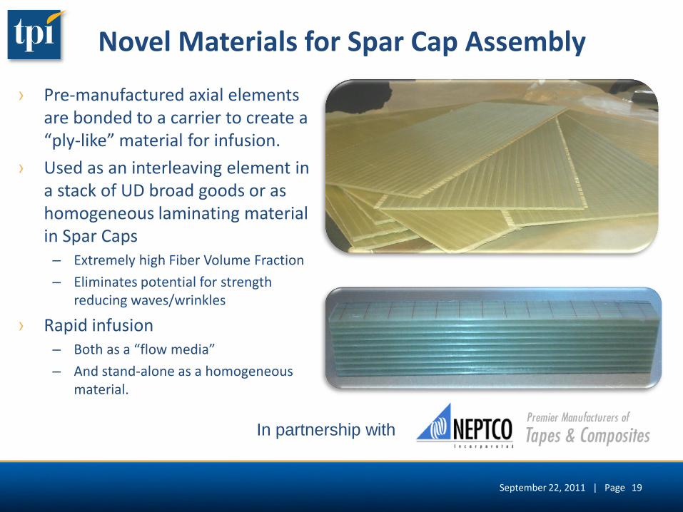
Novel Materials for Spar Cap Assembly
› Pre-manufactured axial elements are bonded to a carrier to create a “ply-like” material for infusion.
› Used as an interleaving element in a stack of UD broad goods or as homogeneous laminating material in Spar Caps – Extremely high Fiber Volume Fraction
– Eliminates potential for strength reducing waves/wrinkles
› Rapid infusion – Both as a “flow media”
– And stand-alone as a homogeneous material.
In partnership with
September 22, 2011 | Page 19
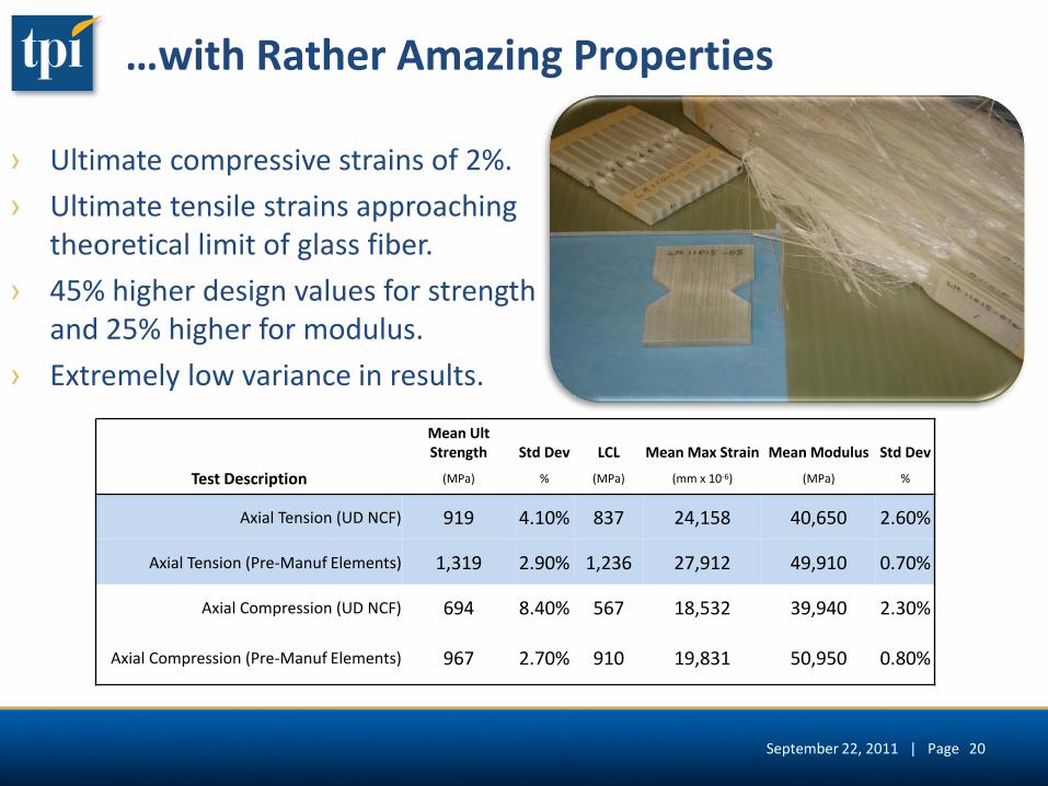
…with Rather Amazing Properties
› Ultimate compressive strains of 2%.
› Ultimate tensile strains approaching theoretical limit of glass fiber.
› 45% higher design values for strength and 25% higher for modulus.
› Extremely low variance in results.
Mean Ult Strength Std Dev LCL Mean Max Strain Mean Modulus Std Dev
Test Description (MPa) % (MPa) (mm x 10-6) (MPa) %
Axial Tension (UD NCF) 919 4.10% 837 24,158 40,650 2.60%
Axial Tension (Pre-Manuf Elements) 1,319 2.90% 1,236 27,912 49,910 0.70%
Axial Compression (UD NCF) 694 8.40% 567 18,532 39,940 2.30%
Axial Compression (Pre-Manuf Elements) 967 2.70% 910 19,831 50,950 0.80%
September 22, 2011 | Page 20
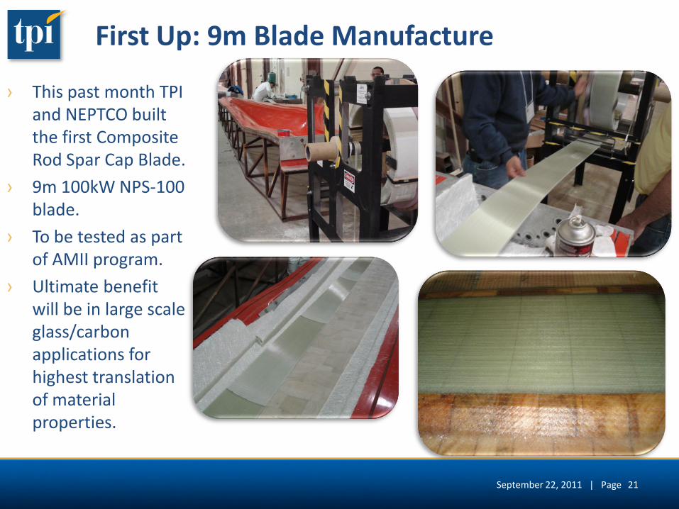
First Up: 9m Blade Manufacture
› This past month TPI and NEPTCO built the first Composite Rod Spar Cap Blade.
› 9m 100kW NPS-100 blade.
› To be tested as part of AMII program.
› Ultimate benefit will be in large scale glass/carbon applications for highest translation of material properties.
September 22, 2011 | Page 21
22
Automation for Blade Production – What’s Coming up for AMII
September 22, 2011 | Page
Automation of Blade Fabrication
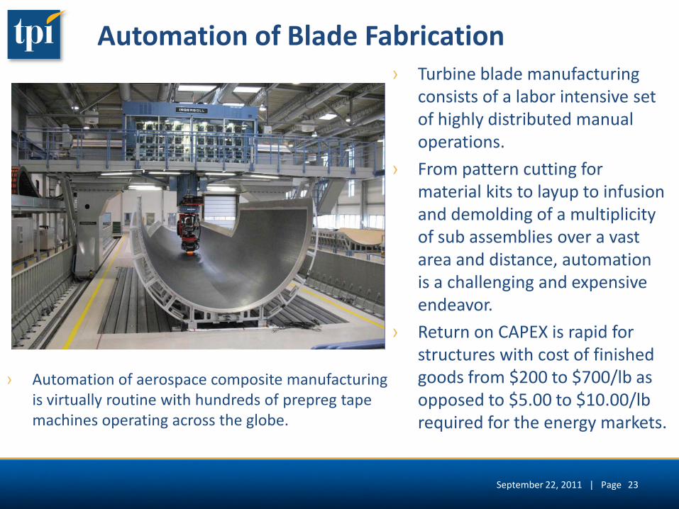
› Automation of aerospace composite manufacturing is virtually routine with hundreds of prepreg tape machines operating across the globe.
› Turbine blade manufacturing consists of a labor intensive set of highly distributed manual operations.
› From pattern cutting for material kits to layup to infusion and demolding of a multiplicity of sub assemblies over a vast area and distance, automation is a challenging and expensive endeavor.
› Return on CAPEX is rapid for structures with cost of finished goods from $200 to $700/lb as opposed to $5.00 to $10.00/lb required for the energy markets.
September 22, 2011 | Page 23
Automation of Blade Fabrication
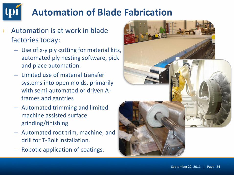
› Automation is at work in blade factories today: – Use of x-y ply cutting for material kits,
automated ply nesting software, pick and place automation.
– Limited use of material transfer systems into open molds, primarily with semi-automated or driven A-frames and gantries
– Automated trimming and limited machine assisted surface grinding/finishing
– Automated root trim, machine, and drill for T-Bolt installation.
– Robotic application of coatings.
September 22, 2011 | Page 24
Automation in Blade Finishing
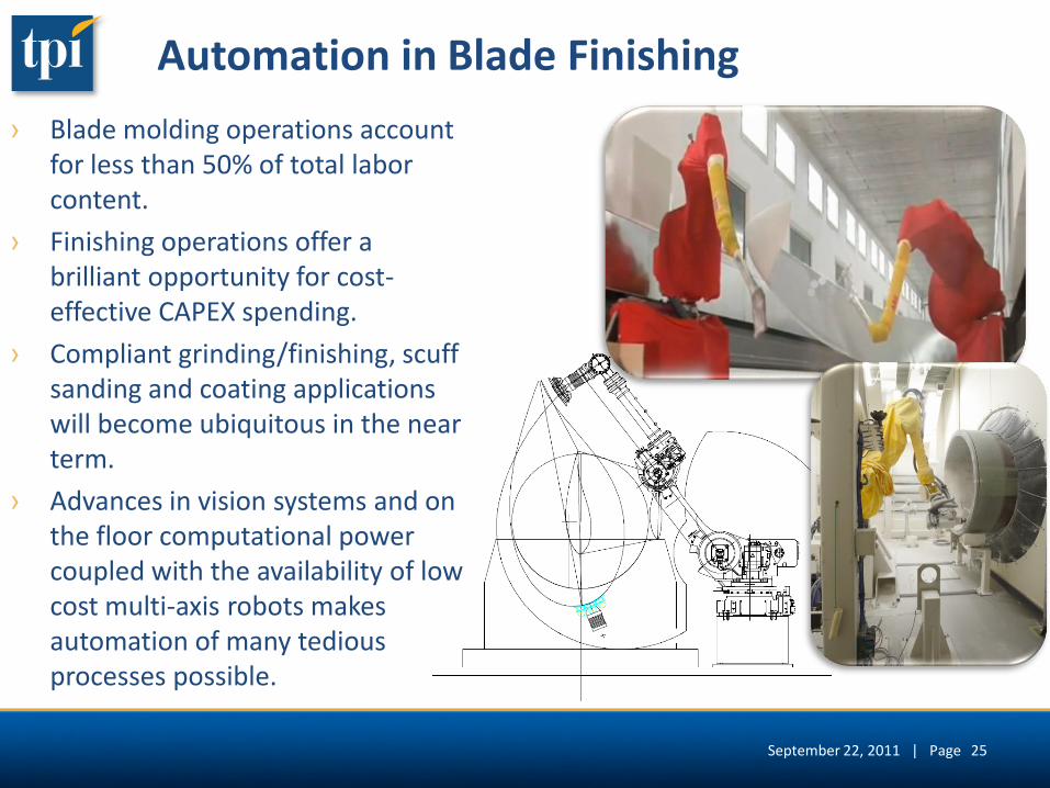
› Blade molding operations account for less than 50% of total labor content.
› Finishing operations offer a brilliant opportunity for cost-effective CAPEX spending.
› Compliant grinding/finishing, scuff sanding and coating applications will become ubiquitous in the near term.
› Advances in vision systems and on the floor computational power coupled with the availability of low cost multi-axis robots makes automation of many tedious processes possible.
September 22, 2011 | Page 25
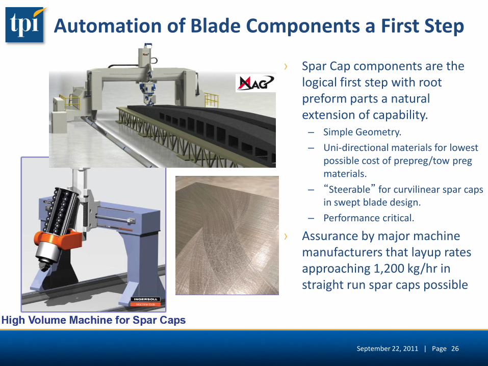
Automation of Blade Components a First Step
› Spar Cap components are the logical first step with root preform parts a natural extension of capability. – Simple Geometry.
– Uni-directional materials for lowest possible cost of prepreg/tow preg materials.
– “Steerable” for curvilinear spar caps in swept blade design.
– Performance critical.
› Assurance by major machine manufacturers that layup rates approaching 1,200 kg/hr in straight run spar caps possible
September 22, 2011 | Page 26
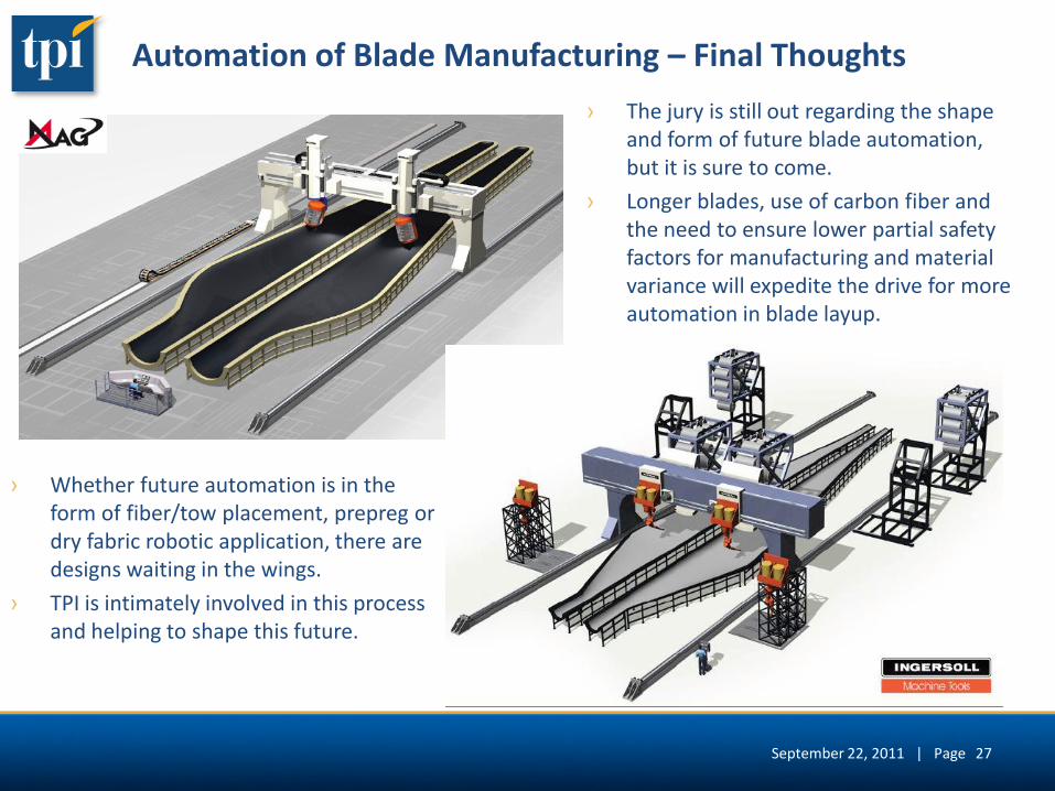
Automation of Blade Manufacturing – Final Thoughts
› The jury is still out regarding the shape and form of future blade automation, but it is sure to come.
› Longer blades, use of carbon fiber and the need to ensure lower partial safety factors for manufacturing and material variance will expedite the drive for more automation in blade layup.
› Whether future automation is in the form of fiber/tow placement, prepreg or dry fabric robotic application, there are designs waiting in the wings.
› TPI is intimately involved in this process and helping to shape this future.
September 22, 2011 | Page 27

Driving Composites Innovation