Embed Size (px)
Citation preview

Internet copy.
ADVANCED MAGNETIC PROPULSION SYSTEMS
(UFOs, Magnocraft, Free Energy Devices) PPaarrtt 22
TThheeoorryy ooff tthhee MMaaggnnooccrraafftt
by
Dr Jan Pajak
Scientific Monograph Dunedin, New Zealand, 1990
ISBN 0-9597698-9-7 © 1990 by Dr Jan Pajak
Updated on 5 July 2010
SCIENTIFIC MONOGRAPH [1e] Author: Jan PAJAK, Doctor of Technical Sciences, Master of Engineering and Engineer (Technical University of Wroclaw, Poland). Title: "Advanced Magnetic Propulsion Systems" (UFOs, Magnocraft, Free Energy Devices). Editorial data: Monograph, 1st New Zealand edition, ISBN 0-9597698-9-7, Dunedin, 1990. Copyright © 1990 by Dr Jan Pajak. All rights reserved. Copying, transmission, or storing of this monograph is subject to the following conditions: #1. A facsimile (copy) of this copyright page must also be included with any copy made of either part or all of this monograph, if this copy is to be used independently from other texts. In the case of incorporating a copy of this monograph into another text, information on the author, title, and editorial data must also be included. #2. For all non-profitable purposes (e.g. studies, education, research, etc.) this monograph can be copied, transmitted, or stored without restrictions, providing that the copies are distributed (or accessible) free of charge, or for the reimbursement of costs only. #3. There are no restrictions on the inclusion of brief quotations from this monograph in a review, private studies, research, or criticism, providing that in any such a quotation the authors contribution is fully acknowledged (i.e. author, title, editorial data, and page number, of this monograph are stated). #4. For purposes involving financial profit (e.g. reprinting in journals, books; presentation in TV programmes; etc.), no part of this monograph may be reproduced in any form or by any means without prior permission in writing from the author. National Library of New Zealand Copyright Deposit No.: PO # 00-017004. Published in Dunedin, New Zealand, 9 October 1990. A private edition by the author. Date of the most recent update of this volume and copy: 30 June 2010 (Note that in case of having access to several copies of this monograph, it is recommended to read the copy which has the latest date of latest distribution/printing.) This monograph is available from Internet through addresses registered in several search engines. Contacts with the author of this monograph: - All correspondence should be addressed to: Dr Jan Pajak P.O. Box 33250 Petone 5046 New Zealand.
- E-mails: [email protected], [email protected], [email protected].

3 3
CONTENTS of [1e], Dunedin 1990, ISBN 0-9597698-9-7: Chapter/subsection Page A. INTRODUCTION A-1 A1. The organization of this monograph A-1 A2. Reference to resource publications A-1 A3. This monograph formally proves that UFOs do exist A-2 A4. How to read this monograph A-3 A5. The history of this monograph A-4 A6. The aims of this monograph A-5 A7. Sponsorship for the building of the Oscillatory Chamber is sought A-6 A8. Constructive criticism as a motive force for the further development of the Theory of the Magnocraft A-7 A9. Milestone Journal articles by the author A-7 PART 1: THE PHILOSOPHICAL FOUNDATIONS B-9 B. THE PERIODIC PRINCIPLE IN THE DEVELOPMENT OF PROPULSION SYSTEMS B-10 B1. Everything in our environment, including the formulation of inventions, is governed by appropriate laws B-11 B2. The basics of propulsion B-11 B2.1. The working medium B-12 B2.2. The primary requirement for building a controllable propulsion system B-13 B3. The content of the Periodic Principle B-13 B4. The first generation of the magnetic propulsion systems B-15 B4.1. The Magnocraft B-16 B4.1.1. The general design and components of the Magnocraft B-16 B4.1.2. Flight control B-17 B4.1.3. The specifications of the Magnocraft B-18 B4.2. The second motor-propulsor pair in the first generation of magnetic propulsion systems B-19 B5. Three successive generations of magnetic propulsion systems B-19 B5.1. How the "omnibus trend" should culminate in three conventions of the Magnocraft's operation B-20 B6. Second generation of magnetic propulsion systems, operating in the telekinetic (teleportative) convention B-21 B6.1. Phenomenon utilized in the second generation of magnetic propulsion systems B-21 B6.1.1. Action of the Telekinetic Effect explained by the Concept of Dipolar Gravity B-23 B6.1.2. Summary of the Telekinetic Effect activated technologically B-25 B6.2. Telekinetic power-stations (or "free energy devices") B-26 B6.2.1. Periodic Table postulating the future completion of telekinetic power-stations B-27
4 4
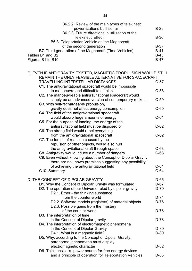
B6.2.2. Review of the main types of telekinetic power-stations built so far B-29 B6.2.3. Future directions in utilization of the Telekinetic Effect B-36 B6.3. Teleportation Vehicle as the Magnocraft of the second generation B-37 B7. Third generation of the Magnocraft (Time Vehicles) B-41 Tables B1 and B2 B-45 Figures B1 to B10 B-47 C. EVEN IF ANTIGRAVITY EXISTED, MAGNETIC PROPULSION WOULD STILL REMAIN THE ONLY FEASIBLE ALTERNATIVE FOR SPACECRAFT TRAVELLING INTERSTELLAR DISTANCES C-57 C1. The antigravitational spacecraft would be impossible to manoeuvre and difficult to stabilize C-58 C2. The manoeuvreable antigravitational spacecraft would simply be an advanced version of contemporary rockets C-59 C3. With self-rechargeable propulsion, gravity does not affect energy consumption C-60 C4. The field of the antigravitational spacecraft would absorb huge amounts of energy C-61 C5. For the purpose of landing, the energy of the antigravitational field must be disposed of C-62 C6. The strong field would repel everything from the antigravitational spacecraft C-62 C7. The forces of reaction caused by the repulsion of other objects, would also hurl the antigravitational craft through space C-63 C8. Antigravity would induce a number of dangers C-63 C9. Even without knowing about the Concept of Dipolar Gravity there are no known premises suggesting any possibility of achieving the antigravitational field C-64 C10. Summary C-64 D. THE CONCEPT OF DIPOLAR GRAVITY D-66 D1. Why the Concept of Dipolar Gravity was formulated D-67 D2. The operation of our Universe ruled by dipolar gravity D-70 D2.1. Ether - the thinking substance from the counter-world D-74 D2.2. Software models (registers) of material objects D-76 D2.3. Possible gains from the mastery of the counter-world D-78 D3. The interpretation of time in the Concept of Dipolar gravity D-78 D4. The interpretation of electromagnetic phenomena in the Concept of Dipolar Gravity D-80 D4.1. What is a magnetic field? D-80 D5. Why, according to the Concept of Dipolar Gravity, paranormal phenomena must display electromagnetic character D-82 D6. Telekinesis - a power source for free energy devices and a principle of operation for Teleportation Vehicles D-83

5 5
D7. The model of the brain as an input-output device D-86 D8. ESP - a key to instant benefits from the counter-world D-90 D8.1. Perfect Data Base (PDB) as a theoretical model of ESP D-93 D8.2. How to develop a simplest pendulum assisted ESP technique D-95 D9. How the Concept of Dipolar Gravity explains some mysterious phenomena D-96 D10. How the Concept of Dipolar Gravity merges science with religion D-99 D10.1. The Universe as a whole possesses its own intellect D-99 D10.2. Moral laws D-101 D10.3. Consistency - the measure of intellectual perfection D-104 D11. An experimental proof for the existence of the counter-world D-104 D12. To conclude D-107 D13. Reference publications D-107 Figures D1 to D8 D-108 E. PHILOSOPHICAL REQUIREMENTS FOR GIVING RECOGNITION TO NEW IDEAS E-115 E1. Everything is possible: we only need to find out how to achieve it E-116 E2. All facts are equal - each of them deserves the same consideration E-117 E3. All statements of others are true unless they are proven to be untrue E-118 E4. Everything can be improved further E-120 E5. Knowledge is responsibility E-121 E6. What is totalizm? E-122 Figure E1 E-124 PART 2: THEORY OF THE MAGNOCRAFT F-125 F. THE OSCILLATORY CHAMBER F-126 F1. Why there is a necessity to replace the electromagnet by the Oscillatory Chamber F-126 F2. The principle of operation of the Oscillatory Chamber F-128 F2.1. The electrical inertia of an inductor as the motive force for oscillations in a conventional oscillatory circuit with a spark gap F-128 F2.2. In the modified oscillatory circuit with a spark gap, the inductance of a stream of sparks replaces the electrical inertia of an inductor F-129 F2.3. The combination of two modified circuits forms an "Oscillatory Chamber" producing a bipolar magnetic field F-131 F3. The future appearance of the Oscillatory Chamber F-132 F4. The condition under which the sparks will oscillate within the Oscillatory Chamber F-133 F4.1. Resistance of the Oscillatory Chamber F-133 F4.2. Inductance of the Oscillatory Chamber F-133
6 6
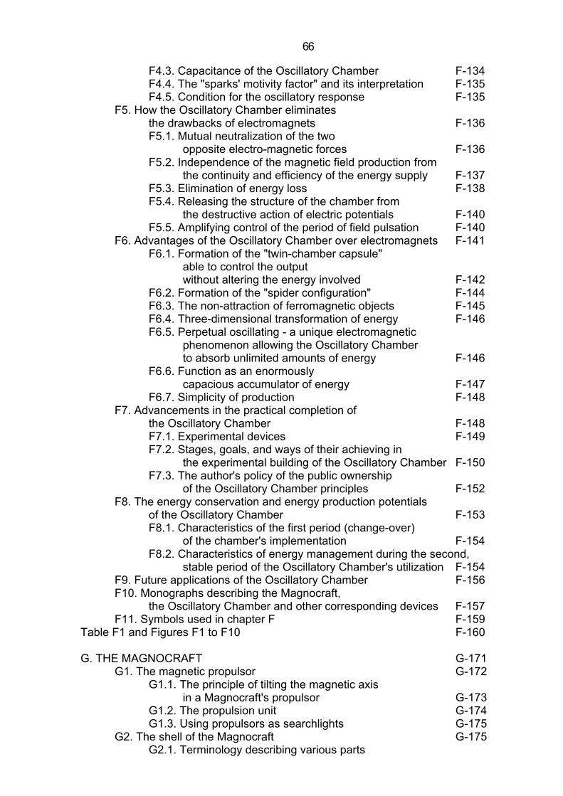
F4.3. Capacitance of the Oscillatory Chamber F-134 F4.4. The "sparks' motivity factor" and its interpretation F-135 F4.5. Condition for the oscillatory response F-135 F5. How the Oscillatory Chamber eliminates the drawbacks of electromagnets F-136 F5.1. Mutual neutralization of the two opposite electro-magnetic forces F-136 F5.2. Independence of the magnetic field production from the continuity and efficiency of the energy supply F-137 F5.3. Elimination of energy loss F-138 F5.4. Releasing the structure of the chamber from the destructive action of electric potentials F-140 F5.5. Amplifying control of the period of field pulsation F-140 F6. Advantages of the Oscillatory Chamber over electromagnets F-141 F6.1. Formation of the "twin-chamber capsule" able to control the output without altering the energy involved F-142 F6.2. Formation of the "spider configuration" F-144 F6.3. The non-attraction of ferromagnetic objects F-145 F6.4. Three-dimensional transformation of energy F-146 F6.5. Perpetual oscillating - a unique electromagnetic phenomenon allowing the Oscillatory Chamber to absorb unlimited amounts of energy F-146 F6.6. Function as an enormously capacious accumulator of energy F-147 F6.7. Simplicity of production F-148 F7. Advancements in the practical completion of the Oscillatory Chamber F-148 F7.1. Experimental devices F-149 F7.2. Stages, goals, and ways of their achieving in the experimental building of the Oscillatory Chamber F-150 F7.3. The author's policy of the public ownership of the Oscillatory Chamber principles F-152 F8. The energy conservation and energy production potentials of the Oscillatory Chamber F-153 F8.1. Characteristics of the first period (change-over) of the chamber's implementation F-154 F8.2. Characteristics of energy management during the second, stable period of the Oscillatory Chamber's utilization F-154 F9. Future applications of the Oscillatory Chamber F-156 F10. Monographs describing the Magnocraft, the Oscillatory Chamber and other corresponding devices F-157 F11. Symbols used in chapter F F-159 Table F1 and Figures F1 to F10 F-160 G. THE MAGNOCRAFT G-171 G1. The magnetic propulsor G-172 G1.1. The principle of tilting the magnetic axis in a Magnocraft's propulsor G-173 G1.2. The propulsion unit G-174 G1.3. Using propulsors as searchlights G-175 G2. The shell of the Magnocraft G-175 G2.1. Terminology describing various parts

7 7
of the Magnocraft's shell G-176 G2.2. The Magnocraft's compartments G-177 G2.3. The Magnocraft's facilities G-178 G2.4. Materials for the Magnocraft's shell G-178 G2.4.1. The electrodynamic model of magnetoreflectiveness G-179 G3. Shapes of the coupled Magnocraft G-179 G3.1. The six classes of the Magnocraft arrangements G-180 G3.1.1. Flying complexes G-181 G3.1.2. Semi-attached configurations G-182 G3.1.3. Detached configurations G-183 G3.1.4. Carrier platforms G-183 G3.1.5. Flying systems G-184 G3.1.6. Flying clusters G-184 G3.2. The principles of coupling and decoupling G-186 G3.3. The hydraulic substance filling the space between the craft ("angel's hair") G-187 G3.4. The black bars of the magnetic field G-188 G4. The conditions defining the shape of the Magnocraft's shell G-188 G4.1. The condition of equilibrium between the thrust and stabilization forces G-189 G4.2. The basic condition for the force stability of the structure of a craft which uses magnetic propulsors G-190 G4.3. The condition for expressing the "K" factor by the ratio of outer dimensions G-191 G4.4. The condition for optimum coupling into flying systems G-192 G4.5. The condition under which the flanges coincide G-192 G4.6. Types of Magnocraft G-193 G4.7. Identifying the types of Magnocraft G-194 G4.8. The magnetic framework G-195 G5. The magnetic field of the Magnocraft G-195 G5.1. The starting flux G-195 G5.2. The naming of the magnetic poles G-198 G5.3. The effective length of the Oscillatory Chamber and the net magnetic force G-197 G5.4. The determination of the value for the starting flux G-198 G5.5. The energy of the Magnocraft's field G-199 G5.6. The energy of the Magnocraft's field is self-rechargeable G-200 G5.7. Why the Earth's magnetic field should not be called "weak" G-200 G5.8. The Earth's magnetic field is able to carry out technically useful work G-201 G6. The manoeuvring of the Magnocraft G-201 G6.1. Ascent, hovering, and descent G-202 G6.2. Meridional flights G-202 G6.3. Latitudinal flights G-203 G6.3.1. An experiment showing the existence of the latitudinal thrust force G-203 G6.3.2. The deduction that explains the principles of the latitudinal thrust force formation G-203 G6.3.3. How to determine the direction of the

8 8
thrust force created by the magnetic whirl (the "rolling sphere rule") G-204 G6.4. The rotation of the Magnocraft G-205 G7. The magnetic whirl G-206 G7.1. The magnetic circuits in the Magnocraft G-206 G7.2. Creation of a magnetic whirl G-207 G7.3. The ionic picture of a whirl G-208 G8. Three modes of the Magnocraft's operation G-209 G8.1. Visual recognition of the mode G-210 G8.2. The SUB system for indicating the Magnocraft's mode of operation G-211 G9. The properties of the Magnocraft G-212 G9.1. The properties of the Magnocraft during the magnetic whirl mode of operation G-212 G9.1.1. Properties of the tunnels made in rocks by the Magnocraft G-213 G9.2. The properties of the Magnocraft during the throbbing mode of operation G-215 G9.3. Humming noises appearing in both the magnetic whirl and throbbing modes of operation G-215 G9.4. The properties of the Magnocraft during the magnetic lens mode of operation G-216 G9.4.1. The magnetic lens action in ascending Magnocraft G-217 G10. The landing sites of the Magnocraft G-217 G10.1. Environmental damage caused by the landed Magnocraft G-218 G10.2. Three main classes of the Magnocraft's landings G-221 G10.3. The landing sites for the magnetic circuits looped under the ground G-222 G10.3.1. Determination of the Magnocraft's dimensions from the scorch marks left at landing sites G-223 G10.4. The landing sites with magnetic circuits looped along the surface of the ground G-225 G10.5. The landing sites for circuits looped in the air G-225 G10.6. The landing sites formed by arrangements of the Magnocraft G-226 G11. Explosion sites of the Magnocraft G-226 G12. Summary of the attributes of the Magnocraft G-229 G13. Military aspects of the Magnocraft G-233 G13.1. Use of the Magnocraft as a weapons platform or transportation facility G-233 G13.2. Use of the Magnocraft as a selectively acting weapon G-234 Tables G1 to G3 and Figures G1 to G42 G-236 H. PERSONAL PROPULSION H-282 H1. The standard garment of Personal Propulsion H-282 H2. A special version of Personal Propulsion with cushions around the hips H-283 H3. The garment with main propulsors in epaulets H-283 H4. Principles of operation of magnetic Personal Propulsion H-284 H5. The attributes of Personal Propulsion H-285 Figures H1 to H4 H-287
9 9
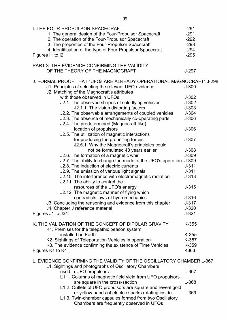
I. THE FOUR-PROPULSOR SPACECRAFT I-291 I1. The general design of the Four-Propulsor Spacecraft I-291 I2. The operation of the Four-Propulsor Spacecraft I-292 I3. The properties of the Four-Propulsor Spacecraft I-293 I4. Identification of the type of Four-Propulsor Spacecraft I-294 Figures I1 to I2 I-295 PART 3: THE EVIDENCE CONFIRMING THE VALIDITY OF THE THEORY OF THE MAGNOCRAFT J-297 J. FORMAL PROOF THAT "UFOs ARE ALREADY OPERATIONAL MAGNOCRAFT" J-298 J1. Principles of selecting the relevant UFO evidence J-300 J2. Matching of the Magnocraft's attributes with those observed in UFOs J-302 J2.1. The observed shapes of solo flying vehicles J-302 J2.1.1. The vision distorting factors J-303 J2.2. The observable arrangements of coupled vehicles J-304 J2.3. The absence of mechanically co-operating parts J-306 J2.4. The predetermined (Magnocraft-like) location of propulsors J-306 J2.5. The utilization of magnetic interactions for producing the propelling forces J-307 J2.5.1. Why the Magnocraft's principles could not be formulated 40 years earlier J-308 J2.6. The formation of a magnetic whirl J-309 J2.7. The ability to change the mode of the UFO's operation J-309 J2.8. The induction of electric currents J-311 J2.9. The emission of various light signals J-311 J2.10. The interference with electromagnetic radiation J-313 J2.11. The ability to control the resources of the UFO's energy J-315 J2.12. The magnetic manner of flying which contradicts laws of hydromechanics J-316 J3. Concluding the reasoning and evidence from this chapter J-317 J4. Chapter J reference material J-320 Figures J1 to J34 J-321 K. THE VALIDATION OF THE CONCEPT OF DIPOLAR GRAVITY K-355 K1. Premises for the telepathic beacon system installed on Earth K-355 K2. Sightings of Teleportation Vehicles in operation K-357 K3. The evidence confirming the existence of Time Vehicles K-359 Figures K1 to K4 K363 L. EVIDENCE CONFIRMING THE VALIDITY OF THE OSCILLATORY CHAMBER L-367 L1. Sightings and photographs of Oscillatory Chambers used in UFO propulsors L-367 L1.1. Columns of magnetic field yield from UFO propulsors are square in the cross-section L-368 L1.2. Outlets of UFO propulsors are square and reveal gold or yellow bands of electric sparks rotating inside L-369 L1.3. Twin-chamber capsules formed from two Oscillatory Chambers are frequently observed in UFOs

10 10
and even photographed L-370 L1.4. Oscillatory Chambers have been seen on the decks of UFOs as described by numerous abductees L-371 L1.5. Indirect confirmations that UFOs use Oscillatory Chambers L-373 L2. Material evidence left by UFO Oscillatory Chambers L-374 L3. Ancient descriptions of the Oscillatory Chamber L-374 L4. Conclusion L-377 L5. Chapter L reference material L-377 Figures L1 to L7 L-379 M. THE MATERIAL EVIDENCE AVAILABLE THAT CONFIRMS THE LONGSTANDING USE OF MAGNOCRAFT-TYPE UFOs M-386 M1. Material evidence on UFO landing sites M-387 M1.1. All three known types of landing sites are formed by visiting extraterrestrial vehicles M-387 M1.2. The value of the Cosmic Cubit can be determined from UFO landing sites M-388 M1.3. The diameters of landing sites confirm the existence of eight basic types of extraterrestrial vehicles M-390 M1.4. Some marks left on the ground document the landing of entire configurations of UFOs (including flying systems) M-391 M1.5. Why UFO landing sites could not be formed by the growth of mushrooms or by any other natural cause M-391 M1.6. There is a critical landing duration after which sites become permanent M-394 M1.7. More that else we can learn from UFO landing sites M-394 M2. Long, straight, geometrically-shaped underground tunnels - material evidence of the ancient operation of the Magnocraft M-396 M3. UFO explosion sites M-398 M3.1. The Tapanui Crater M-399 M3.2. The Tunguska Explosion M-405 M3.3. What can be learned from both explosion sites (i.e. Tapanui and Tunguska) M-408 M4. Fragments of UFO vehicles found on Earth M-410 Figures M1 to M30 M-411 N. SIGHTINGS OF UFONAUTS WHO USE MAGNETIC PERSONAL PROPULSION N-441 N1. The characteristic appearance of the wearers of personal propulsion N-441 N2. The extraordinary abilities of UFOnauts wearing personal propulsion garments N-442 N3. The scorched footprints left by personal propulsion of a UFOnaut N-443 N4. The consequences of the sighting of personal propulsion of UFOnauts N-444 Figures N1 to N6 N-446 O. CONTEMPORARY SIGHTINGS OF FOUR-PROPULSOR UFOs O-452 O1. Classic sightings of four-propulsor UFOs O-452 O2. Photographs of four-propulsor UFOs O-454

11 11
O3. Concluding this chapter O-454 Figures O1 to O3 O-455 P. HOW TO ORGANIZE EDUCATIONAL COURSES DEDICATED TO "EXPLAINING THE UNEXPLAINED" P-458 Figures P1 to P2 P-460 Q. ABOUT THE AUTHOR Q-462
F-125
Part 2:
THEORY OF THE MAGNOCRAFT The second part of this monograph which follows concentrates on the presentation of theoretical deductions that form the nuclei of what the author calls the "Theory of the Magnocraft". The name for this part originates from the term "Magnocraft", attributed to the basic vehicle invented and developed as the consequence of applying this theory. The Theory of the Magnocraft describes the system of principles, ideas, deductions and inventions which constitute the conceptual foundations for this completely new approach to the propulsion of interstellar spacecraft. In this approach the propelling forces are created as the effect of magnetic interactions occurring between the field produced by the spacecraft itself and a planetary, solar or galactic magnetic field. The further applications of the Magnocraft's principles of operation allow also for the creation of two other useful propulsion systems, such as Magnetic Personal Propulsion (shifting of individual people without using any vehicle), or the Four-Propulsor Spacecraft (for the transporting of cargo of any possible shape and dimensions). The important component of the Theory of the Magnocraft is the principle of operation of the unique device allowing for the production of a magnetic field of unlimited strength, called an "Oscillatory Chamber". This device represents an "engine" for the Magnocraft and for two other propulsion systems that are based on the Magnocraft. At present the Oscillatory Chamber represents the only principle known which makes it possible to raise the device's output over the value of the so-called "starting flux", and therefore which may be used for propelling a spacecraft. (The "starting flux" is the magnetic equivalent of the "escape velocity" which restricts conventional space travel. It defines such minimal value of a magnetic flux produced by a given source of a magnetic field that is able to lift this source into space solely as the effect of its repulsive interaction with the Earth's magnetic field.) Of course, it can not be excluded that apart from the Oscillatory Chamber, some other principles of magnetic field production will be invented in the future, which will also provide outputs sufficiently high to lift space vehicles (e.g. the "pulsatory conglomerate" mentioned in chapter B). The entire Theory of the Magnocraft is subdivided into four parts, each one of which is dedicated to the description of a separate device, and each of which is presented in a different chapter. The Oscillatory Chamber is described in chapter F that follows, the Magnocraft in chapter G, Magnetic Personal Propulsion in chapter H, and the Four-Propulsor Spacecraft in chapter I.
F-126
Chapter F:
THE OSCILLATORY CHAMBER The name "Oscillatory Chamber" is given to a completely new principle of magnetic field production which employs the effects of the oscillation of electric sparks. These sparks circulate around the inner perimeter of a cubical chamber made of an electric insulator and filled with a dielectric gas. The four packets of electrodes, joined to the inner surfaces of four side walls of this chamber, perform alone the function of two oscillatory circuits with a spark gap. Each one of these two circuits is created by two packets of electrodes attached to two opposite walls. The appropriate formation of the oscillatory discharges occurring in both these circuits allows for the production of a dipolar magnetic field. The principles applied for this production not only eliminate from the chamber the drawbacks of today's electromagnets, but also provide the Oscillatory Chamber with a variety of unique operational advantages. The complete elimination of drawbacks inherent in the electromagnets is ensured by the following attributes of the chamber: 1.The elimination of electromagnetic forces acting on the structure of the chamber. 2. Leaving to the user's choice the time and amount of energy supply (i.e. each portion of energy, whatever its amount and whenever it is delivered, is collected, stored, converted into a magnetic field and released when necessary). 3. The recovery and conversion back into electricity of all the energy dissipated by sparks. 4. The channeling of the destructive consequences of the accumulation of huge electric charges into the direction which reinforces the chamber's proper operation. 5. The independence of the power of control devices from the power involved in field production (i.e. a weak control signal will cause a change in the enormously powerful field produced by the chamber). The Oscillatory Chamber displays also the following unique advantages unknown in any other appliance built by man to date: A. The ability to absorb and store theoretically unlimited amounts of energy. B.Full controllability over all properties and parameters of the field produced, achieved without any change in the level of energy contained in it. C. Producing the kind of magnetic field which does not attract, nor repel, ferromagnetic objects (i.e. which behaves like a kind of "antigravity field", not a magnetic one). D. Three dimensional transformation of energy (electricity/ magnetic field/heat) which allow the Oscillatory Chamber to take over the function of almost every other conventional energy-converting device (e.g. electromagnets, transformers, generators, accumulators, cells, combustion engines, heaters, air conditioners, etc.). As the final result of such a formation of the Oscillatory Chamber, this device, when completed, will be able to raise the value of a produced magnetic flux to a level unlimited by theoretical premises. Practically it also means that this source of field will be the first one able to lift itself as the effect of a repulsive interaction with the Earth's magnetic field. F1. Why there is a necessity to replace the electromagnet by the Oscillatory Chamber The recent achievements in the development of propulsion systems prompt one to ask the question: What is this remarkable principle of controlled magnetic field production of which today's technology can be so proud? The answer is (at the beginning of the space
F-127
exploration era): exactly the same principle as the one which was used over 170 years ago, i.e. the principle discovered by the Danish professor, Hans Oersted, in 1820, depending on the application of the magnetic effects created by an electric current flowing through the coils of a conductor. The device utilizing this principle, called an electromagnet, is now one of the most archaic appliances still in common use. We can realize how outdated its operation is from the following example: if the progress in propulsion systems were equal to that of magnetic field production devices, our only mechanical vehicle would still be a steam engine. Electromagnets possess a whole range of drawbacks, which make it impossible to raise their output above a particular - and not very high - level. These disadvantages can in no way be eliminated, because they result from the principle of operation of these devices alone. Below are listed the most significant drawbacks of electromagnets: (1) Electromagnets create deflecting forces which tense their coils in the radial direction trying to tear coils apart. These forces are produced as the result of mutual interaction between the magnetic field produced by an electromagnet, and the same coils of the conductor which created this field. The field tries to push these coils out from its own range (see the "left-hand rule" often called the "motor effect"). The deflecting forces so formed in coils are of a type identical to the ones utilized in the operation of electric motors. In order to prevent the electromagnet from being torn apart, these electromagnetic containment forces must ultimately be resisted by some form of physical structure. This increases the weight of any really powerful steady-field magnet, whose output must be balanced by the mechanical strength of its structure. When the current's flow in electromagnets exceeds a certain level, the deflecting forces grow to such an extent that they cause the coils to explode. Therefore, too high an increase in the output of electromagnets results in their self-destruction (explosion). (2) Electromagnets must be continuously supplied with electric current if they are to produce a magnetic field whose all parameters are controllable (i.e. a field whose parameters can be changed in accordance with the application requirements). If such continuous energy supply is cut off, the controllability over the electromagnet's field finishes. This requirement of controllability causes that during the production of powerful magnetic fields, a single electromagnet consumes the output from a whole electricity plant. (3) Electromagnets cause significant energy losses. The electric current flowing through coils of a conventional electromagnet releases a vast amount of heat (see Joule's law of electric heating). This heat not only decreases the energetic efficiency of the magnetic field production, but also, when the energies involved are high, it leads to a melting of the coils. The superconductive electromagnet removes the heating from a current flowing through resistance. However, it introduces another loss of energy resulting from the necessity to maintain a very low temperature of the coils. This also causes a permanent consumption of energy which decreases the efficiency of such a magnet. Moreover, it should be noted here that the high density of magnetic fields cancels the effect of superconductivity and thereby restores a resistance to the coils. (4) Electromagnets are prone to electric wear-out. The geometrical configuration of electromagnets is formed in such a way that the direction of the greatest electric field strength does not coincide with the path of the conductor through the coil. This directs the destructive action of electric energy into the insulation, causing its eventual damage (short-circuit followed by the electric breakdown) which initiates the destruction of the entire device. (5) Electromagnets can not be controlled by weak signals. The parameters of their magnetic field can be controlled only through the changes in the power of the electrical energy supply. Therefore controlling the electromagnets requires the same powers as those powers involved in the production of a magnetic field. The only way to eliminate the five disadvantages listed above is to apply a completely different principle of magnetic field production. Such a principle, invented by the author, will be presented in later sections of this chapter. Because this new principle utilizes
F-128
the mechanism of oscillatory discharges occurring inside a cubical chamber, it is called an "Oscillatory Chamber". The principle of the Oscillatory Chamber avoids the limitations which prevent an increase of output in electromagnets. Also, it promises a more effective and convenient preparation and exploitation, long life without the necessity of maintenance, a very high field-to-weight ratio, and a wide range of applications (e.g. energy storage, propulsion devices, sources of magnetic fields, etc.). The explanations that follow (especially the one from subsection F5) will describe the mechanisms for achieving this. Therefore, it appears highly desirable to promote the fast development of this device in the not-too-distant future so that it may replace electromagnets presently in use. F2. The principle of operation of the Oscillatory Chamber The electric current flowing through a wire is not the only source of a controlled magnetic field. The other well-known source is the phenomenon manifesting the flow of electric energy in its purest form, i.e. an electric spark. There are many different methods for the creation of electric sparks, but the purpose considered here is best served by the so-called "oscillatory circuit with a spark gap". The unique property of such a circuit is its ability to absorb, total and utilize the energy supplied to it. This energy then appears in the form of a gradually diminishing sequence of oscillatory sparks created by the circuit. The discovery of the oscillatory circuit with a spark gap was achieved in 1845 by the American physicist, Joseph Henry, who noticed that when a Layden jar was discharged through coils of wire, the discharge and a spark were oscillatory. A few years later Lord Kelvin, the great English physicist and engineer, proved mathematically that the discharge in a circuit so constituted must manifest itself in the oscillatory form. F2.1. The electrical inertia of an inductor as the motive force for oscillations in a conventional oscillatory circuit with a spark gap Figure F1 "a" shows a conventional configuration of the oscillatory circuit with a spark gap. The most distinctive characteristic of this configuration is that it is constituted by connecting together into one closed circuit the configuration of three vital elements, i.e. L, C1 and E, which have the form of separate devices. These elements are: (1) inductor L, containing a long wire wound into many coils, which provides the circuit with the property called an "inductance"; (2) capacitor C1, whose property, called a "capacitance", allows the circuit to accumulate electric charges; (3) electrodes E, whose two parallel plates ER and EL, separated by a layer of gas, introduce a "spark gap" to the circuit. When the electric charges "+q" and "-q" are supplied to the plates PF and PB of the capacitor C1, this forces the flow of an electric current "i" through the spark gap E and the inductor L. The current "i" must appear in the form of a spark "S" and must also produce the magnetic flux "F". The mechanisms of consecutive energy transformations occurring within the inductor L and described in many books on electronics, cause the spark "S", since once created between electrodes E, to continue oscillating until the energy involved is dissipated. The oscillatory circuit with a spark gap represents an electric version of the device which produces one of the most common phenomena of nature, an oscillatory motion. The mechanical analogy of this device, well-known to everyone, is a swing. In all devices of that type, the occurrence of oscillations is caused by the action of the Conservation Energy Principle. This principle compels the initial energy provided to such an oscillating system to be bound in a continuous process of repetitive transformations into two forms: potential and kinetic. The "potential energy" within the oscillatory circuit is represented by the opposite electric charges "+q" and "-q" carried within both plates of a capacitor - see Figure F1 "a". The electric potential difference introduced by the presence of these charges causes the flow of an electric current "i" through the circuit. In a swing, the same potential energy is
F-129
introduced by slanting the arm of it away from the vertical position. As a result, a load (e.g. a swinging child) is raised to a particular height, later forcing its own acceleration down into the equilibrium position. The second from of energy, the "kinetic energy", within the oscillatory circuit manifests itself in the from of a magnetic flux "F" produced by the inductor L. In a swing this kinetic energy appears as the speed of a load's motion. The mutual transformation of the potential form of energy into a kinetic one, and vice versa, requires the involvement of an agent which activates the mechanisms of energy conversion. This agent is introduced by the element possessing the property called "inertia". Inertia is a motive force maintaining the oscillations within any oscillating system. It works as a kind of "pump" which forces the transformations of energy from a potential form, through a kinetic one, back into a reversed potential form. This "pump" always restores the initial amount of potential energy existing at the beginning of the oscillation's cycle, decreased only by its dissipation occurring during the transformations. Therefore the inertial element is the most vital component of every oscillating system. In the oscillatory circuit its function is performed by the inductor L, whose inductance (expressed in henrys) represents electrical inertia. In the swing, mechanical inertia is provided by the mass of a load (expressed in kilograms). This is the reason why the inductance in the electric oscillations is considered to be the equivalent of the mass from the mechanical oscillations. To increase mechanical inertia it is necessary to join additional mass to that which is already involved in the energy transformations. The increase of electrical inertia requires the extending of the length of an electric current flow, exposed to the action of its own magnetic field. Practically this is obtained by building an inductor containing many coils of the same wire, closely wound, so that each of them is within the range of the magnetic field produced by the other coils. Let us review the mechanism of oscillations within the oscillatory circuit shown in Figure F1 "a". We assume that initially the plates PB and PF of the capacitor C1 carry the opposite electric charges "-q" and "+q" and that the current "i" within the inductor L is zero. At this instant the whole energy of the circuit is stored in the potential form in the capacitor C1. The opposite charges accumulated on the plates of the capacitor C1 create an electromotive force which activates the current flow "i". To facilitate the interpretation of the sparks' behaviour, in this publication the electric current is defined as a movement of electrons from negative to positive. The current "i" appears on the electrodes E in the form of a spark "S", whereas in the inductor L it produces a magnetic flux "F". As the difference of charges "q" on the plates of the capacitor C1 decreases, the potential energy stored in the electric field also decreases. This energy is transferred to the magnetic field that appears around the inductor because of the current "i" that is building up there. Thus the electric field decreases, the magnetic field builds up and energy is transformed from the potential to the kinetic form. When all the charge on the capacitor C1 disappears, the electric field in the capacitor will be zero, and the potential energy stored there will be transferred entirely to the magnetic field of the inductor L. The electromotive force which before caused the current "i" to flow is now eliminated. But the current in the inductor continues to transport the negative charge from the PB plate of the capacitor C1 to the PF plate, because of the electrical inertia. This preserves the current "i" (therefore also the spark "S") from extinction and maintains its flow at the cost of the kinetic energy contained in the magnetic field. Energy now flows from the inductor L back to the capacitor C1 as the electric field builds up again. Eventually, the energy will have been transferred back completely to the capacitor C1. The situation now reached is like the initial situation, except that the capacitor is charged in the reverse way. The capacitor will start to discharge again, and the whole process will repeat itself, this time in the opposite direction. Once started, such oscillations continue until the resistance of this process dissipates the energy involved. F2.2. In the modified oscillatory circuit with a spark gap, the inductance of a stream of sparks replaces the electrical inertia of an inductor
F-130
It is known that an electric spark alone introduces a high electric inertia. Therefore a spark is able to replace the inductor in providing the inductance to the circuit. The condition of such a replacement is that the spark must possess the appropriate active length and also that its path must follow a course within the range of its own magnetic field. To achieve this condition, it is impossible to repeat the solution used in the inductor, because an electric spark is reluctant to wind itself into the form of consecutive coils. However, the same can be achieved in another way, through replacing a single spark by a whole stream of sparks jumping simultaneously along parallel paths. Each single spark in such a stream will be the equivalent of one coil of wire within an inductor. All sparks together will provide the necessary inductance to the circuit. Figure F1 "b" shows the author's modified version of the oscillatory circuit with a spark gap, which makes use of the electrical inertia of the stream of parallel jumping sparks. The most distinctive characteristic of this version is that all three vital components of the Henry's circuit, i.e. inductance L, capacitance C1 and spark gap E, are now provided by a single physical device, which simultaneously performs three different functions. The modified device consists of only a couple of conductive plates PF and PB, attached to the inner surfaces of two opposite walls of a cubical chamber made of an electric insulator and filled with a dielectric gas. Each of the plates is divided into a number of small segments each insulated from the other (in the diagram marked by 1, 2, 3, ..., p). Each pair of facing segments marked by the same number, e.g. "p", forms a single component capacitor, which after receiving a sufficient electric charge transforms itself into a couple of electrodes exchanging the electric spark "Sp". The total number of all electric sparks jumping simultaneously in the form of a single compact stream provides the device with the required inductance. To summarize the modification described above, one can say that the three separate devices, each of which has provided the conventional circuit with one selected property, are now replaced by the single device (i.e. a pair of plates) simultaneously providing all three vital properties, i.e. L, C and E. If the principle of operation of this modified oscillatory circuit is considered, it becomes obvious that it is identical to Henry's circuit. After all segments of both plates are uniformly charged, the potential energy of the circuit is built up. When the difference of potentials between plates overcomes the breakdown value "U", the discharge is initiated. This discharge will take the form of a stream of parallel sparks S1, S2, S3, ..., Sp, joining facing segments of the plates. The magnetic field produced by these sparks will gradually absorb the energy stored initially within the electric field. When both plates PF and PB reach the equilibrium of potentials, the electrical inertia of sparks will continue the transmission of the charge between them, transforming the kinetic energy contained within the magnetic field back into the potential energy of the electric field. Therefore at the end of the first stage of the oscillation of sparks, the plates will again contain the initial charge, but of the opposite kind. Then the whole process repeats itself but in the reverse direction. If the slight dissipation of energy occurring in this device is somehow compensated for, the process described above will be repeated endlessly. Such an operation of the modified oscillatory circuit liberates all the electric phenomena from material ties. In effect the electric current does not need to flow through a wire and its value is not the subject of limitation by the properties of the materials used. Also the electric phenomena are exposed to a controlling action that allows them to be channeled into the desired course. These are very important achievements, and as it will be proved later, they are the source of many of the advantages of this device. The sequence of sparks that oscillate in the device shown in Figure F1 "b", will produce an alternating magnetic field. Because the stream of sparks follows the same path in both directions, this field will also be a vortex, i.e. have all force lines lying on parallel planes. Such a field will not display clear polarity, because its magnetic poles N and S are not fixed. To create a bipolar magnetic field with the steadily positioned magnetic poles N and S, it is necessary to continue one step further in the development of this modified oscillatory circuit.
F-131
F2.3. The combination of two modified circuits forms an "Oscillatory Chamber" producing a bipolar magnetic field The final form of the circuit considered here is shown in Figure F1 "c". This is the form to which the name "Oscillatory Chamber" has been ascribed. The Oscillatory chamber is constituted by combining together two circuits indicated as C1 and C2, both identical to the one presented in Figure F1 "b". Therefore it consists of four segmented plates (i.e. twice as many as in the modified oscillatory circuit in Figure F1 "b"), indicated as PF, PB, PR and PL (i.e. front, back, right and left). Each of these plates contains the same number of segments "p", and faces the other identical plate, together with this other plate forming one of the two co-operating oscillatory circuits. Both of these circuits produce the four streams of sparks marked as SR-L, SF-B, SL-R, and SB-F, which oscillate between opposite plates. These sparks appear in succession, one after the other, having the mutual phase shift between them equal to one quarter of a period of their entire sequence ( T). Before the mechanism of the discharges in this final configuration is analyzed, we should remind ourselves of the action of the electromagnetic containment forces which will try to deflect the sparks away from the range of the bipolar magnetic field. They are the same forces which cause the explosion of coils in powerful electromagnets. In the case of the Oscillatory Chamber, these forces will push the stream of sparks against the plate along which the discharge occurs. For example all sparks within the stream SR-L jumping from the plate PR to the plate PL will be pushed to the surface of the plate PF (at this moment the plate PF increases its own negative charge). For this reason the individual sparks forming consecutive streams SR-L, SF-B, SL-R, and SB-F, instead of crossing the paths of the other sparks, will bend themselves at the edges of the chamber and produce a kind of rotating arc. Notice that the plate along which the sparks are jumping is prevented from being entered by them. This prevention mainly depends on the formation of the plate from a large number of small segments (needles), each insulated from the other, and therefore the resistance against conduction along the plate is not less than the resistance of the discharge through the dielectric gas in the chamber. Let us assume that the initial charging of the Oscillatory Chamber is provided in such a way that first the stream of sparks marked as SR-L will occur, and then after a period of time equal to t= T - the stream SF-B (compare Figure F1 "c" with Figure F3). Let us also assume that right from this initial time, along the vertical (magnetic) axis "m" of the chamber the magnetic flux "F", produced by this device, prevails. This flux pushes sparks against the side walls. After the initial charging of the C2 capacitor, at the time t=0, the stream of sparks SR-L will appear, which will jump from plate PR to plate PL. These sparks produce the magnetic flux "F" which is totalled to the one already existing in the chamber. The flux bends the paths of all these sparks, pushing them close to the surface of plate PF. At time t= T the potentials of plates PR and PL reach an equilibrium, but the inertia of sparks SR-L still continues transporting charges from PR to PL, at the cost of the kinetic energy accumulated in the magnetic field. At the same instant (t= T) the operation of the second circuit begins and the jump of the SF-B stream of sparks is initiated. Similarly this stream produces a magnetic field which pushes it against the surface of plate PL. So in the timespan t= T to t= T, there are two streams of sparks present, SR-L and SF-B, the first of which transfers energy from the magnetic to the electric field, whereas the second one transfers energy from the electric to the magnetic field. At time t= T the plates PL and PR reach a difference of potentials equal to the initial one (at t=0), but with the opposite location of charges. Therefore the stream of sparks SR-L disappears, whereas the stream SL-R jumping in an opposite direction is now initiated. This stream is pushed to the surface of plate PB. At the same instant (t= T) the plates PF and PB reach the equilibrium of potentials, so that the stream of sparks SF-B passes into its inertial stage. In the timespan t= T to t=3/4T there are two streams of sparks, i.e. SF-B and SL-R, the first of which consumes the magnetic field, whereas the other produces it. At the instant t=3/4T the
F-132
sparks SF-B disappear and the sparks SB-F are formed (pushed against plate PR), whereas the sparks SL-R are passing into their inertial stage. At time t=1T the sparks SL-R also disappear and the sparks SR-L are created (pushed against the plate PF), whereas the sparks SB-F pass into their inertial stage. With this the whole cycle of the sparks' rotation is closed, and the situation at time t=1T is identical to the one at the initial moment t=0. The process that follows will be a repetition of the cycle just described. The above analysis of the sequence and paths of the sparks reveals a very desirable regularity. The streams of sparks turn into a kind of electric arc combined from the four separate segments. This arc rotates around the inner perimeter of the Oscillatory Chamber. Such a process, in accordance with the rules of electro-magnetism, must produce a strong, pulsating, bipolar magnetic field. The obtaining of such a field crowns the long and difficult search for the new method of the magnetic field production presented here. The principle of operation of the Oscillatory Chamber does not require a strictly cubical shape for this device, and can also be executed in any chamber consisting of four rectangular side walls of identical dimensions. The only condition is that its cross-section in a plane perpendicular to the magnetic axis "m" must be a square. In this publication, however, for simplicity in deduction, only the cubical shape is considered. We should also consider the characteristics of the magnetic field produced by the Oscillatory Chamber. If we analyze the field produced by only a single stream of sparks, it would be a discrete pulsating field of approximately half-sinusoidal course, which, at the points where the sparks reverse, would drop to zero. Because in the chamber two streams of sparks always appear simultaneously, the resultant field will follow the course described approximately by totalling together the series of positive halves of sinusoids. It will still pulsate, but will contain a constant component and a varying component. The relation between both components, as well as the course of the varying component, will be determined by the amount of energy involved in the pulsations. F3. The future appearance of the Oscillatory Chamber It is not difficult to satisfy the requirements of the Oscillatory Chamber for construction materials. This device can be made of practically anything, provided that its housing is a good electric insulator and its electrodes made of good electric conductors. Moreover, all parts should be magnetically neutral. So even ancient material available thousands of years ago, such as wood and gold, can be used. If made out of these, the Oscillatory Chamber would look like an ordinary wooden box or cube. Its appearance would not indicate its hidden power. At our present level of technological development there are available transparent non-conductors, which are also excellent robust construction materials. If the housing of the chamber were made of them, it would reveal to the observer the contents of this device. Contemporary electronics has also created a high demand for transparent conductors, which can already be found in some watches and calculators. The quality of these conductors will gradually improve and we may soon expect their properties to be comparable to those of metals. Let us assume that the Oscillatory Chamber will be made wholly of such transparent materials. Therefore the casual observer of the chamber in operation will notice it has the form of a very simple transparent cube - see figure F2. Along the inner surfaces of the plain side walls of this cube, bright gold shimmering sparks will flash. Although these sparks will flicker, they will appear to be frozen in the same positions. Their paths will closely follow the inner surface of the plates, because of the electromagnetic containment forces pushing the sparks against the walls of the chamber. The inside of the cube will be filled with a dielectric gas and an extremely concentrated magnetic field. This field, when observed from the direction perpendicular to its force lines, will be impenetrable to light, looking like dense black smoke. It is very noticeable in any scientific exhibition or "open day" in a laboratory, that when a demonstrator starts up an apparatus producing sparks, for example a Tesla coil, an
F-133
Induction coil or a Van de Graaff machine, spectators irresistibly gravitate towards the display. Claps of thunder and lightning flashes have always possessed a kind of mysterious, hypnotic power which acts on everyone and which provides memorable experiences. The power emanating from inside the Oscillatory Chamber will similarly capture the attention and imagination of people witnessing it. Future observers of the operation of this device will have the impression that they are facing an unknown living creature, absorbed in the fulfilment of its own fascinating and mysterious physiological functions, rather than seeing a piece of machinery engaged in its ordinary process of operation. The wealth of energy, trapped, curbed and waiting within the walls of the chamber, will fascinate witnesses, leaving them with a multitude of vivid impressions, indelibly etched on their memories. Observing this transparent cube, one will find it difficult to imagine that to reach the point of its creation, this device, so simple in structure, required the accumulation of almost 200 years of human knowledge and experience. F4. The condition under which the sparks will oscillate within the Oscillatory Chamber Our present knowledge of magnetic and electric phenomena enables us to deduce the equations expressing the values of the resistance, inductance and capacitance of the Oscillatory Chamber. Further combination of these equations will lead to the prediction of the behaviour of this device. F4.1. Resistance of the Oscillatory Chamber The general form of the equation for the resistance of any resistor of cross section "A" and length "l" is as follows: R = Ω*(l/A) In this equation the " " represents the resistivity of a material from which the resistor is made. In our case it will be the maximal resistivity of the dielectric gas that fills the Oscillatory Chamber, determined for the conditions of the initial moment of electric breakdown. If in the above general equation, we replace the variables by the specific parameters determined for the Oscillatory Chamber, i.e. l=a and A=a (compare with Figure F1 "b"), this gives: R = Ω/a (F1) The equation received represents the resistance of the Oscillatory Chamber, which is a function of the chamber's side wall dimension "a". F4.2. Inductance of the Oscillatory Chamber The determination of the chamber's inductance is an extremely difficult and complex task. It is beyond the author's knowledge of the subject. Also a number of experts consulted in this matter were unable to help. (Perhaps some of the readers know how to resolve this problem - all advice will be warmly welcomed.) Being unable to find the exact solution, the author decided to apply temporarily a simplified one. To justify this simplification it should be stated that the deducted equation for inductance (F2) will be used only once in the entire
F-134
monograph, when the meaning of factor "s" (see (F5)) is interpreted. Therefore all the vital equations in this work remain unaffected. In the simplified deductions of the chamber's inductance an assumption is made that a unitary inductance of a stream of sparks (i.e. the inductance related to the unit of a spark's length) will be equal to the inductance of the equivalent strand of wires. This assumption allows for the application of a well-known equation for the inductance of a solenoid (see "Fundamentals of Physics" by David Halliday et al, John Willey & Sons, 1966): L = µ*n5*l*A When in this equation we substitute: n=p/a, l=a, and A=a*a (where "p" is the number of segments in each of the chamber's plates, whereas "a" is the dimension of the chamber's walls), the simplified equation for the inductance of the Oscillatory Chamber is derived: L = µ*p5*a (F2) It can be theoretically asserted that the unitary electrical inertia of a stream of sparks should be greater than such an inertia in the equivalent strand of wires. The justification for this assertion can be obtained from the analysis of the inertia mechanism. The inertia reveals itself only when the motion involves the reversible phenomena or media which absorb energy in the initial stage of the motion's development, and which release this energy when the motion declines. The greater the number of such phenomena and media involved, and the higher their energy absorption, the larger is the resultant inertia. The stream of sparks jumping through gas in every aspect manifests better potentials for causing an inertia higher than the one of a current flowing through wires. The first reason for this lies in the more efficient energy absorption and releasing by sparks, occurring because: a) The speed of electrons in a spark can be higher than in a wire, b) The contiguous sparks can pass closer to each other because they do not require thick insulation layers in between them (as is the case for wires). The second reason for the higher inertia of sparks in gas results from their involving a variety of reversible phenomena - not appearing at all during flows of currents through wires. These are: c) The ionization of surrounding gases. This, due to the returning of the absorbed energy, supports the inertia of the process at the moment of the sparks' decline. d) The causing of the motion of heavy ions, whose mass absorbs and then releases the kinetic energy. e) The initiation of hydrodynamic phenomena (e.g. dynamic pressure, rotation of the gas) which also will be the cause of the charges' dislocation and energy return at the moment of the sparks' decline. The above theoretical premises should not be difficult to verify by experiments. F4.3. Capacitance of the Oscillatory Chamber When we use the well-known equation for the capacitance of a parallel-plate capacitor, of the form: C = ε*(A/l) and when we apply the substitutions: A=a , l=a, this yields the final equation for the capacitance of the Oscillatory Chamber: c = ε*a (F3)
F-135
F4.4. The "sparks' motivity factor" and its interpretation Each of the relations (F1), (F2) and (F3) describes only one selected parameter of the Oscillatory Chamber. On the other hand, it would be very useful to obtain a single complex factor which would express simultaneously all electromagnetic and design characteristics of this device. Such a factor is now introduced, and will be called a "sparks' motivity factor". Its defining equation is the following: s = p*(R/2)*/(C/L) (F4) Notice, that after expressing this in the notation of computer languages, in which the symbol "*" means multiplication, the symbol "/" means division, the symbol "+" means addition, the symbol "-" means subtraction, while the symbol "sqrt()" means the square roof from the parameter provided in brackets "()", the above equation (F4) takes the following form: s = p*(R/2)*sqrt(C/L).
Notice that, according to the definition, this "s" factor is dimensionless. Independently from the above defining equation, the "s" factor has also an interpretative description. This is obtained when in (F4) the variables R, L and C are substituted by the values expressed by equations (F1), (F2) and (F3). When this is done, the following interpretative equation for "s" is received: s = (1/(2a))Ω/(ε/µ) (F5) Notice, that after expressing this in the notation of computer languages, in which the symbol "*" means multiplication, the symbol "/" means division, the symbol "+" means addition, the symbol "-" means subtraction, while the symbol "sqrt()" means the square roof from the parameter provided in brackets "()", the above equation (F5) takes the following form: s = (1/(2*a))*Ω*sqrt(ε/µ).
Equation (F5) reveals that the "s" factor perfectly represents the current state of all environmental conditions in which the sparks occur, and which determine their course and effectiveness. It describes the type and consistency of the gas used as a dielectric, and the actual conditions under which this gas is stored. It also describes the size of the chamber. Therefore the "s" factor constitutes a perfect parameter which is able to inform exactly about the working situation existing within the chamber at any particular instant in time. The value of the "s" factor can be controlled at the design stage and at the exploitation stage. At the design stage it is achieved by changing the size "a" of a cubical chamber. At the exploitation stage it requires the change of the pressure of a gas within the chamber or altering its composition. In both cases this influences the constants ε, µ and Ω, describing the properties of this gas. F4.5. Condition for the oscillatory response From the electric point of view the Oscillatory Chamber represents a typical RLC circuit. The research on Electric Networks has determined for such circuits the condition under which, once they are charged, they will maintain the oscillatory response. This condition, presented in the book by Hugh H. Skilling, "Electric Network" (John Willey & Sons, 1974), takes the form: R < 4(L/C) If the above relation is transformed and then its variables are substituted by the equation (F4), it takes the final form: p > s (F6)
F-136
The above condition describes the design requirement for the number "p" of segments separated within the plates of the Oscillatory Chamber, in relation to the environmental conditions "s" existing in the area where the sparks appear. If this condition is fulfilled, the sparks produced within the Oscillatory Chamber will acquire an oscillatory character. To interpret the condition (F6), a possible range of values taken by the factor "s" should be considered (compare with the equation (F5)). Such a consideration allows us to conclude that, in the majority of cases, any number "p" of segments should provide the oscillatory sparks. F5. How the Oscillatory Chamber eliminates the drawbacks of electromagnets The operation of the Oscillatory Chamber is formed in such a way that all drawbacks significant for electromagnets are completely avoided in this device. The descriptions that follow present the principle of elimination for each basic disadvantage of electromagnets listed in section F1. F5.1. Mutual neutralization of the two opposite electromagnetic forces The unique operation of the Oscillatory Chamber leads to the formation of two reciprocally acting forces: (1) the Coulomb's attraction force, and (2) the electromagnetic deflecting force. The opposite electric charges, which are accumulated on the facing walls of the chamber, attract each other, causing the formation of the Coulomb forces that compress this device inwards. The electromagnetic containment forces, created by the interaction of the magnetic field and the sparks, cause the tension of the Oscillatory Chamber outwards. Therefore it is possible to select the design and operational parameters of this device, so that both kinds of forces mentioned above will mutually neutralize each other. As the final result, the physical structure of the chamber is liberated from the obligation to oppose any of these forces. Figure F3 presents the mechanism of reciprocal compensation of these two interactions described above. For simplicity, all the courses of phenomena within the chamber are shown as linear, independently of how they occur in reality. But it should be noticed that these phenomena are symmetrical. It means that, for example, if the current in the sparks changes in a particular way, the potentials on the plates must also change in exactly the same way. Therefore the variation in time of the forces analyzed here will display some kind of an inherent regulation mechanism, in which the course (not the quantity) of the first phenomenon always follows the course of the other phenomenon opposite from this first one. Part "a" of Figure F3 shows the four basic phases forming the full cycle of the chamber's operation. The description of these phases is already provided in subsection F2.3 of this chapter. Significant for each phase is that two streams of sparks co-exist, the first of which (indicated by the continuous line in diagram F3 "a") transmits energy from the electric field into the magnetic field (active sparks). The second stream (in the diagram indicated by a broken line) in this instant consumes the magnetic field to produce the electric field (inertial sparks). Part "b" of Figure F3 illustrates the relevant changes of electric charges "q" on the R (right), L (left), F (front) and B (back) plates of the chamber, occurring during each phase of the device's operation. These charges create the Coulomb's forces that attract the facing plates inwards. In this part of the diagram it is visible that, when one pair of plates reaches the maximum of its potentials differences - initiating a discharge between them, the other pair is just in its equilibrium of potentials. Then simultaneously with the growth of the discharge current flowing between this first pair of plates, the opposite charges on the other pair of plates also grow. The containment forces that tense the chamber outwards are
F-137
growing accordingly with the value of the discharge current. On the other hand the Coulomb's force of the reciprocal attraction of these other facing plates is growing as well, together with the quantity of opposite electric charges accumulated on them. Part "c" of Figure F3 shows the changes in the electromagnetic containment forces M=i a B, trying to push out the particular sparks from the field's range. Because these forces are proportional to the produce of the sparks' current "i" and the magnetic flux density "B=F/(a·a)", the maximum of the chamber's tension will occur at the instant of time when the discharging plates reach the equilibrium of their potentials. At this same instant of time the other pair of plates, along which the discharge occurs, reaches the maximum of potentials difference (compare with part "b" of this diagram) as well as the maximum force of their reciprocal compression. In part "d" of Figure F3 is shown the mechanism of mutual compensation of the forces described above. The upper side of this diagram presents the changes in the tension forces "T" which try to pull the Oscillatory Chamber apart. These forces are caused by the interaction of the magnetic field and the current from the sparks (compare with part "c" of this Figure). The lower side of diagram "d" presents the changes in the compression forces "C". This compression is caused by the mutual Coulomb's attraction of the facing plates that accumulate the opposite electric charges "q" (compare with part "b" of Figure F3). Note that whenever a tension force appears (e.g. from the sparks SB-F), always there is also formed a counteracting compression force (e.g. from the Coulomb's attraction of charges qR-L). Both of them act in opposite directions, and follow the same course of changes in time. Therefore both neutralize each other. It is natural that the compensation of forces, displaying inherence in their course as described above, still requires that values match. Therefore further experimental research will be necessary, to select such design and exploitation parameters of the Oscillatory Chamber that will provide the full equilibrium for the counteracting forces. As a result of this research, a device can be completed in which the production of a magnetic field will not be affected by the action of any kinds of forces. F5.2. Independence of the magnetic field production from the continuity and efficiency of the energy supply One of the most basic attributes of the oscillating systems is their capability for the discrete absorption of the energy supplied, which is then bound into a continuous process of oscillations. An example of this is a child on a swing, which, once pushed, then swings a long time without any further work. Practically it means that the energy once supplied to the Oscillatory Chamber will be tied up within it for a period of time until the circumstances occur which will cause its withdrawal. As will be explained in item F5.3 of this chapter, such withdrawal can appear only when the chamber is involved in performing some kind of external work. The other attribute of the oscillating systems is their ability to change the level of energy accumulated in them by a periodic totalling of further portions of energy to the resources already stored. In the previous example of a swing, to cause the slanting of a child at a particular height, it is not necessary to apply all effort at once. It is sufficient to keep pushing gently over a longer timespan and to maintain periodically this addition of energy. The consequence of this attribute will be that the Oscillatory Chamber will not require the supply of its full reserve of energy at once. The energy supply to this device can be gradual, spread over a very long period of time. Both of these attributes together give us a practical chance for supplying the unlimited energy required for the production of a magnetic field, without introducing any requirements or limitations concerning the source and the channel which provide this supply. To help us realize the advantage of the above method of supplying energy to the Oscillatory Chamber over the one used in electromagnets, we should consider the following
F-138
example. A child on a swing and an athlete both try to lift a heavy load to a specific height. The child does it almost without effort by accumulating the energy during consecutive oscillations, whereas the athlete needs to use all his/her strength and still may not achieve his/her aim. F5.3. Elimination of energy loss Sparks are well-known for their inherent dissipation of energy. There is no doubt that such an intensive circulation of sparks, like the one appearing within the Oscillatory Chamber, must convert an enormous amount of electrical energy into heat. In an ordinary device such a conversion would become a source of significant energy loss. But in the chamber unique conditions appear which make possible the direct conversion of heat into electricity. This conversion allows for the recovery back into the opposite electric charges of all the energy dissipated into the heat produced by the sparks. So within the chamber two opposite processes will occur simultaneously: (1) the energy dissipation in (and around) the sparks, manifesting itself as the conversion of electrical energy into heat, and (2) the energy recovery by the direct conversion of heat into electrical energy. Both these processes will mutually neutralize each other's effects. Therefore no matter how high the energy dissipation by the sparks themselves, the Oscillatory Chamber as a whole will fully eliminate their energy loss. As the result of such an elimination, all energy provided to this device will be preserved within it forever, unless some kind of external work is done which will cause its retrieval. In the Oscillatory Chamber, the magnetic field (whose force lines are accelerated and decelerated by sparks' motion), electrodes (whose charges fluctuate), and a dielectric gas (highly ionized by the discharges and caused to rotate by the circulating streams of sparks) coexist. This provides all conditions necessary for the direct conversion of heat into electricity. Within the chamber the following methods of such a conversion can be employed: (1) electro-gas-dynamic, (2) magneto-hydro-dynamic (MHD), and (3) telekinetic. In the electro-gas-dynamic method, heat is converted into electricity by hot rotating gas. This gas transfers the electric charges (produced by the ionization of gas) and deposits them on electrodes. The energy consumed during this transfer is withdrawn from the gas, causing a decrease in its temperature. In the magneto-hydro-dynamic method, heat is converted into electricity as a result of the action of Faraday's law of electromagnetic induction. As we know, every electric conductor moved through a magnetic field experiences the Lorentz force and an induced electric field causing a current to flow. The work needed for displacing this conductor against the Lorentz force is then converted into electricity and recovered in the form of an electric work. This principle of electromagnetic induction may also be employed when a rotating hot gas is used as the movable conductor. In such a case the conversion process can be called a magneto-hydro-dynamic (MHD) energy conversion. Its direct consequence is the decrease in the gas temperature. In the telekinetic method heat is converted directly into electricity through the application of telekinetic motion. Chapter D and subsection B6.1.1 of this monograph describe the Concept of Dipolar Gravity which explains the difference between the physical and telekinetic motion. According to this concept, the telekinetic motion is caused not by the action of a force, but by the action of the so-called "Telekinetic Effect". The action of this effect can be released technologically through the acceleration and deceleration of magnetic fields. The Telekinetic Effect represents a reversal of friction, i.e. it spontaneously absorbs environmental heat and produces motion (friction spontaneously converts mechanical motion into heat). There is even a class of devices already built, called free energy devices, which utilize the Telekinetic Effect for converting the environmental heat into the motion of electrons (i.e. electricity). The Oscillatory Chamber provides all the conditions required to employ the Telekinetic Effect for the direct conversion of heat (produced by sparks) into electricity. For this reason, the third and the most promising
F-139
method of heat recovery which can be effectively employed in the chamber is the telekinetic method. One of the stereotyped opinions which prevail among scientists is that the conversion of thermal energy into any other form of energy must always obey the Carnot principle of thermodynamical efficiency. The adherents of this view automatically carry it over to the Oscillatory Chamber without considering the unique conditions occurring within it, whereas any mechanical application of the laws of thermodynamics to the Oscillatory Chamber is a gross over-simplification, overlooking the following factors of extreme importance: 1. The so-called "laws" of thermodynamics are in fact not laws, but statistical predictions of the total cause of numerous chaotic events. 2. The behaviour of gas particles in the presence of a strong magnetic field displays order, not chaos. Therefore the course of the energy conversion within the Oscillatory Chamber can not be described by the laws of thermodynamics. 3. Even without considering the future ways of a direct conversion of heat into electricity, such as the application of telekinetic motion, at our present level of knowledge such perfectly efficient methods are already known. For example, the principle of the magneto-hydro-dynamic energy conversion assures perfect efficiency in thermal energy recovery. Therefore, if such conversion is deprived of the thermodynamic (chaotic) factor, as this will be the case in the Oscillatory Chamber, such a perfect recovery can be obtained. Because these three factors are vital to the Oscillatory Chamber, and they don't seem to be realized by some readers, let us explain their meaning more precisely. Refer 1. The statistical character of the laws of thermodynamics has been acknowledged for quite a long time. James Clerk Maxwell (1831-1879), the author of the famous equations of electromagnetism, presented proof based on the action of the so-called "Maxwell's demon", which demonstrates that the validity of these laws may be abolished in some exceptional situations. Quoted below is what B.M. Stableford writes about the second of these laws in his book "The Mysteries of Modern Science" (London 1977, ISBN 0-7100-8697-0, page 18): "The law of thermodynamics was shown to be a result of the statistical aggregation of a large number of events rather than an inviolable principle ruling the world with an iron hand. ... we can begin to see that although the law of thermodynamics always works out in practice, it could, in fact, be subverted by an extremely unlikely combination of chance happenings - it is not a law so much as a statistical prediction." Refer 2. It is a well-known phenomenon that a strong magnetic field stops the chaotic behaviour of the particles of a gas (fluid) and arranges them into an ordered pattern. This phenomenon is the basis for operation of some computer memories, and it is also applied to so-called "magnetic cooling" - see the book by J.L. Threlkeld, "Thermal Environmental Engineering" (Prentice-Hall, Inc., N.J. 1962, page 152). Therefore a magnetic field itself carries the capability of performing the function of "Maxwell's demon", able to abolish the validity of the laws of thermodynamics. So it is justified to expect that, in the presence of such a field, energy conversion will not obey the Carnot principle. Refer 3. The principle of magneto-hydro-dynamic energy conversion contains the potential for perfect energy recovery. This potential is very well expressed in the following quotation taken from the book by J.P. Holman "Thermodynamics" (McGraw-Hill, Inc., 1980, ISBN 0-07-029625-1, page 700): "From an energy point of view, the movement of force through a displacement (mechanical work) is converted to electrical work (current flow against potential difference) by means of the electromagnetic induction principle. This is a work-work energy conversion and is not limited by the Carnot principle."
F-140
The unique conditions occurring within the Oscillatory Chamber eliminate the thermodynamical (chaotic) factor which reduces the efficiency of this process in ordinary circumstances, and allows the energy conversion to achieve perfect efficiency. The deduction presented above shows that there are quite realistic and well-based premises signaling the possibility of a complete recovery of the energy loss within the Oscillatory Chamber. All that is needed now is that we do not close our minds to such a possibility, but implement it practically in this device. The elimination of loss of energy is not the only advantage of the direct conversion of heat into electricity which may be achieved within the Oscillatory Chamber. This conversion also introduces an easy method for maintaining the energy supply to the device. To increase the energy resources contained within the Oscillatory Chamber the additional heating of its dielectric gas will alone be sufficient. This heating can be obtained, for example, by the circulation of the dielectric gas through a heat exchanger, or by concentrating a beam of sunlight on it. Combining the lack of energy loss with the independence of the magnetic field production from the continuity of energy supply (compare with item F5.2 of this chapter), provides the Oscillatory Chamber with the property at present characteristic only for permanent magnets. The magnetic field, once created in this device, will maintain itself through the centuries if the external consumption of energy does not occur. F5.4. Releasing the structure of the chamber from the destructive action of electric potentials The distinctive property of the Oscillatory Chamber is that it accumulates on facing plates electric charges of equal values but opposite signs (the same number of negatives as positives). Under such circumstances the force lines of an electric field from facing plates will mutually bind themselves together. This causes the charges to display a tendency to jump along the shortest trajectories joining these electrodes. Therefore in the chamber the tendency for a natural flow of electric charges will coincide with the trajectories required for the operation of this device. As a result, the material of the chamber's casing is freed from the action of the electric charges, whereas all the power of the device's energy is directed towards the production of a magnetic field. In the channelling of the electric energy flow described above, the Oscillatory Chamber is entirely different from electromagnets. In the chamber this channelling is achieved by employing natural mechanisms of electrostatic attraction. In electromagnets it was forced artificially by the appropriate formation of the insulator's layers, which pushed the current to flow along the coils, whereas the action of the electric field's force lines was trying to push it across the coils and through the insulation. Therefore there is reason to expect that the Oscillatory Chambers will possess a life incomparably longer than that of electromagnets, and that their lifespan will not be limited by an electrical wear-out. How destructive such an electrical wear-out of insulation is we may learn by analyzing the lifespan of coils working under high voltages. A well-known example is the ignition coil in cars, which usually breaks down after about 7 years of usage, while still displaying no sign of mechanical defect. In low voltage electromagnets this process is slower, and therefore may not be noticed by users. But it will appear eventually. F5.5. Amplifying control of the period of field pulsation The Oscillatory Chamber will manifest a very high controllability. The key to the manipulation of its operation is the period of pulsations "T". From the RLC circuits we know that the period of their oscillations is described by the equation: T = (2*π)/(sqrt(1/(L*C) - (R/(2*L))**2) = 2*π*sqrt(L*C/(1 - ((R**2)*C)/(4*L)))
F-141
Notice, that after expressing this in the notation of computer languages, in which the symbol "*" means multiplication, the symbol "/" means division, the symbol "+" means addition, the symbol "-" means subtraction, the symbol "x**2" means "x" to the power of "2", while the symbol "sqrt()" means the square roof from the parameter provided in brackets "()", the above equation takes the following form: T = (2*π)/(sqrt(1/(L*C) - (R/(2*L))**2) = 2*π*sqrt(L*C/(1 - ((R**2)*C)/(4*L))).
If the defining equation (F4) on the factor "s" replaces in the above a combination of R, L, and C parameters, whereas equation (F1) and equation (F3) provide the values for R and C, then this period is described as: T = (π*(p/s)*Ω*ε)/sqrt(1 - (s/p)**2) Notice, that after expressing this in the notation of computer languages, in which the symbol "*" means multiplication, the symbol "/" means division, the symbol "+" means addition, the symbol "-" means subtraction, division, while the symbol "sqrt()" means the square root from the parameter provided in brackets "()", the equation (F7) takes the following form: T = (π*(p/s)*Ω*ε)/sqrt(1 - (s/p)**2). The final equation (F7) shows how easily the value of "T" can be controlled in the Oscillatory Chamber. At the exploitation stage it is sufficient to concentrate controlling activities on the change of the "s" factor only. By changing the pressure of the gas filling the Chamber, or by altering its composition, the "s" factor is influenced. The change in "s" factor in turn introduces the changes in period "T" of the field's pulsations. To illustrate the essence of the above principle of the chamber's output control, we would need to imagine a hypothetical electromagnet in which all design parameters, i.e. the resistivity of wire, the number of coils, and also the geometrical configuration of a conductor, could easily be changed during its operation. Only such an imaginary electromagnet would allow for the output control in a manner used by the Oscillatory Chamber, i.e. through the appropriate manipulation of its design parameters, and without the necessity of controlling the power of a current supplied to it. Of course, in reality such an electromagnet is impossible to build. The above illustration shows that the chamber uses a very different (and much more convenient) control of oscillations than the one used in real electromagnets. In the Oscillatory Chamber the changes of the dielectric gas constants: Ω, ε and µ - causing the change of "s", are not dependent on the necessity to manipulate the amounts of energy contained in the electric and magnetic fields. Therefore in this device all controlling activities no longer involve wrestling with the power contained inside the chamber. As a result the power of the control devices is independent from the power of the produced field (i.e. weak control devices can effectively alter the parameters of a powerful field). But in electromagnets every change in a magnetic field requires manipulations to be conducted on highly energetic currents. Thus control of electromagnets involves the same powers as field production. Of course, every method of control introduces its own disadvantages. Such is also the case in the tuning system described above. We may predict here some limitations in the range of control - caused by critical damping, and the influence on the intensity of heat generation - caused by changes in the resistivity of gas. But these disadvantages can be overcome technically, and they are insignificant when compared with the advantage of making the power of a controlling device independent from the power of the controlled energy flows. F6. Advantages of the Oscillatory Chamber over electromagnets The elimination of the drawbacks of electromagnets is not the only achievement of the principle of the Oscillatory Chamber. This device introduces in addition a number of
F-142
unique advantages which are not provided by any other device built by man to-date. Let us review the most important of them. F6.1. Formation of the "twin-chamber capsule" able to control the output without altering the energy involved Further possibilities of controlling the output from the Oscillatory Chamber are created when two such cubical devices are arranged together to form a configuration called the "twin-chamber capsule" - see Figure F4. This capsule consists of one small inner chamber "I" freely suspended (floating) in the centre of the outer chamber "O". To insure the free flotation of the inner chamber without the danger of distending and damaging the outer one, the side dimension "ao" of the outer chamber must be 3 times larger than the dimension "ai" of the inner one, i.e.: ao = ai/3 (F8) (the equation (F8) expresses the requirement that the longest diagonal dimension of the inner cube can not exceed the shortest distance between two parallel walls of the outer cube). Both chambers are so arranged that their central axes coincide with the magnetic axis "m" of the entire capsule. But the magnetic polarities of both chambers are reversed, i.e. the poles of the inner chamber are oriented exactly in opposition towards the poles of its host (i.e. "S" of the inner chamber is directed towards "N" of the outer one, and vice versa). This opposite polarity of both chambers causes their outputs to mutually cancel (subtract) each other. The effect of this cancellation is that most of the force lines of the magnetic field produced by one chamber do not leave the capsule, but are circulated back into the other chamber. Therefore the magnetic field yield out to the environment by such a capsule represents only the difference between the outputs produced by its inner and outer chambers. In the so-formed twin-chamber capsule the appropriate control of the chambers' periods of pulsation "T" allows the energy content in both chambers to be either maintained unchanged, or to be transferred from one chamber to the other. Therefore both chambers can either produce the same output, or a greater output can be produced by any of the component devices (i.e. by the outer "O" as well as by the inner "I" chamber). Technically, the balance or the transfer of energy between both chambers depends only on a phase shift between the periods "To" and "Ti" of their pulsations. (As this was described in subsection F5.5, these periods in turn are controlled, according to the equation F7, solely by changing the "s" factors of the chambers' dielectric gases.) In general, when both chambers pulsate in harmony (i.e. have zero phase shift) they maintain their energy content without any change. But when the phase shift between their pulsations is formed, the magnetic energy begins to shift between both chambers. The bigger this phase shift is, the more energy flows from one chamber to the other. The direction of flow is from the chamber whose pulsations obtain a leading phase shift (i.e. whose period "T" was speeded up towards the period "T" of the other chamber) to the chamber whose pulsations are slower. To illustrate the above with an example, let us imagine two people on separate swings bound together by an elastic (rubber) rope. When they swing with zero phase shift (i.e. when their movements exactly correspond) the energy of their oscillations remains unaffected. But when they form a phase shift in their oscillations, the person whose swing is ahead will pull the other one through the elastic rope. In this way the energy will flow from the faster swinger to the slower one. When both chambers of a twin-chamber capsule yield exactly the same output, the force lines of a magnetic field produced by the inner chamber "I" are forming a close loop with the magnetic field produced by the outer chamber "O". This loop is locked inside the capsule. Therefore in such a case both chambers may produce an extremely high magnetic field, but this field will be entirely "circulated" inside of the capsule, and no magnetic flux will appear outside of the capsule. The magnetic flux trapped in such a looping and hermetically locked inside a twin-chamber capsule is called the "circulating flux". In illustrations from this
F-143
chapter it is labeled (C). The circulating flux performs an important function in the twin-chamber capsules, as it bounds and stores the magnetic field which later may be used as the capsules' energy supply. Therefore the circulating flux in twin-chamber capsules of the future will represent the equivalent to "fuel" from the contemporary propulsion systems. But when the energy content in both chambers of a capsule is unequal, as illustrated in Figure F4, the magnetic flux produced by this chamber, which has a greater output, is divided into two parts, i.e. (R) the "resultant flux" conducted to the outside of the twin-chamber capsule, and (C) the "circulating flux" involved in internal looping within the chamber having a smaller output. At the same time the magnetic flux produced by the device having a smaller output is entirely involved in the circulating flux and is not conducted outside the capsule. In Figure F4 the greater output is produced by the outer chamber "O", therefore its flux is divided into the (C) and (R) parts. But the entire output of the inner chamber "I" in this Figure is involved in the circulating flux (C). Because the greater magnetic flux can be produced either by the inner or the outer chamber, the twin-chamber capsules can operate in two modes called: (1) the "INNER flux prevalence", and (2) the "OUTER flux prevalence". In the mode of INNER flux prevalence, the resultant flux is produced by the inner chamber, whereas the outer chamber circulates its entire output inside the capsule. In the mode of OUTER flux prevalence, the resultant flux is produced by the outer chamber, whereas the inner chamber bounds its entire output into the circulating flux. The visual appearance of capsules operating in these two modes is shown in Figure F5. The differences in their appearance result from the fact that a highly dense magnetic field is transparent only to an observer who looks at it along its force lines. For the observer looking from any other direction such a field is non-transparent, and resembles black smoke. Therefore an outside observer looking at the twin-chamber capsule's outlet should see only the interior of that chamber which produces the resultant flux running into his/her direction, whereas the outlines of the remaining chamber which produces a circulating flux would appear to be black. The twin-chamber capsule puts into the environment only the resultant flux that represents a difference from the outputs of both chambers. The circulating flux is always locked inside this capsule and never reaches the environment. Therefore, this configuration of chambers allows the fast and efficient control over the resultant magnetic flux conducted to the environment. This control is achieved without a change in the total amount of energy contained in the capsule, and only through shifting this energy from the outer to the inner chamber and vice versa. Practically, this means that the output given by the capsule to the environment can be easily changed, while the energy content of the capsule remains all the time at the same level. In order to realize the enormous capabilities of such control, the most important states of the magnetic field put into the environment by the twin-chamber capsule are described below. (1) The complete extinguishing of the capsule's output. If the inner and the outer chambers contain the same amount of magnetic energy and produce equal magnetic fluxes, their entire production is looped inside of the twin-chamber capsule and no field is conducted to the environment. Of course, in such a case the enormous magnetic energy of the capsule still remains trapped inside of it, and can be redirected outside at any time by a simple alteration in the capsule's controls. (2) A smooth (or discrete) change of the capsule's magnetic output within the range from its minimal (i.e. zero) to maximal value. Such a change in the resultant output requires only appropriate transfer of the magnetic energy from one chamber into the other. The maximal output from this capsule is achieved when one of its chambers concentrates almost all of the energy, whereas the output from the remaining chamber is almost zero. (3) The production of a magnetic field that has any required orientation of the magnetic poles. Depending on which of two chambers (inner or outer) reaches a dominating (prevailing) output, the polarity of the resultant flux (R) will reflect the polarity of this dominating chamber. (4) An almost instant reversal of polarity for the capsule's resultant magnetic output (e.g. the exchange of its north pole into the south pole, and vice versa). This reversal can
F-144
be achieved merely by shifting quickly the magnetic energy between two chambers and without any need for a mechanical rotation of the capsule. The ability to strictly control the variations in time (curvature) of the resultant flux is another advantage of the twin-chamber capsules. An example of such control, concerning the resultant flux whose variations in time follow a beat-type curve, is shown in Figure F6. When the frequencies of pulsations in both chambers are different (e.g. when the inner chamber produces a flux "FI" whose frequency is two times higher than the frequency of the flux "Fo" produced by the outer chamber), the algebraic subtraction of both these fluxes produces a bit-type variation in time of the resultant flux "FR". In this way, through the altering of frequencies of inner and outer fluxes, a wide range of resultant flux variations in time can be obtained. It is equally simple to produce a pulsating resultant flux following one of many possible beat-type curves, as well as a number of alternating fields of different courses. In each of these cases the period of the resultant flux variation can be controlled at the required level. On the other hand, when the frequencies of oscillations in both chambers are the same, then the two counter-oriented magnetic fluxes mutually suppress their pulsating components. If this coincides with the equal amplitudes of fields from both chambers, the resultant flux "FR" is then non-oscillating (constant in time), identical in character to the one provided by the permanent magnets. Because of the direct relationship existing between the frequency "f" and the period "T" of the field pulsation (f=1/T), the entire control over the resultant flux curvature is also achieved through the alterations of the "s" factor, as has already been described in subsection F5.5. The above explanations demonstrate how easy and versatile the control capabilities of twin-chamber capsules are. Of course this will have a definite bearing on the future applications of these arrangements of chambers. It is easy to predict that almost all advanced magnetic propulsion systems of the future will utilize twin-chamber capsules instead of just single Oscillatory Chambers. Out of all the propulsion systems described in this monograph, such capsules will be used in the propulsors of the Magnocraft (see descriptions in chapter G) and in Personal Magnetic Propulsion (see descriptions in chapter H). F6.2. Formation of the "spider configuration" The twin-chamber capsule is not the only configuration into which a number of Oscillatory Chambers can be arranged in order to increase the controllability of their resultant flux (R). The other configuration displaying even wider possibilities is the so-called "spider configuration", shown in Figure F7. In the spider configurations the chambers are arranged so that one of them, called the main chamber (M), is surrounded by the four side chambers indicated by the letters U, V, W, and X. Each of these five chambers possesses the same cross section, but the volume (thus also the length) of the main one is equal to the sum of the volumes of all four side ones. The magnetic poles in the main Oscillatory Chamber (M) are directed in opposition to the orientation of the poles in the side chambers (U, V, W, X). This new configuration of the Oscillatory Chambers is a simplified model of the Magnocraft's propulsion described in the next chapter of this monograph (the Magnocraft contains a single twin-chamber capsule (propulsor) placed in its centre, and a multiple of four of twin-chamber capsules arranged around its peripherals). Also the operation of the spider configuration closely imitates the operation of the Magnocraft's propulsion. Therefore this configuration in fact constitutes a kind of miniature Magnocraft. As well, the magnetic field produced by it displays all the attributes of the Magnocraft's field, for example its force lines may spin around the magnetic axis of the main chamber. The above reasons decide that the spider configuration found its best application in the propulsion of the so-called "four propulsor Magnocraft", described in chapter I. The control over the value of a resultant flux (R) produced by the spider configuration is exactly the same as it is in the twin-chamber capsule. Therefore the magnetic field yield
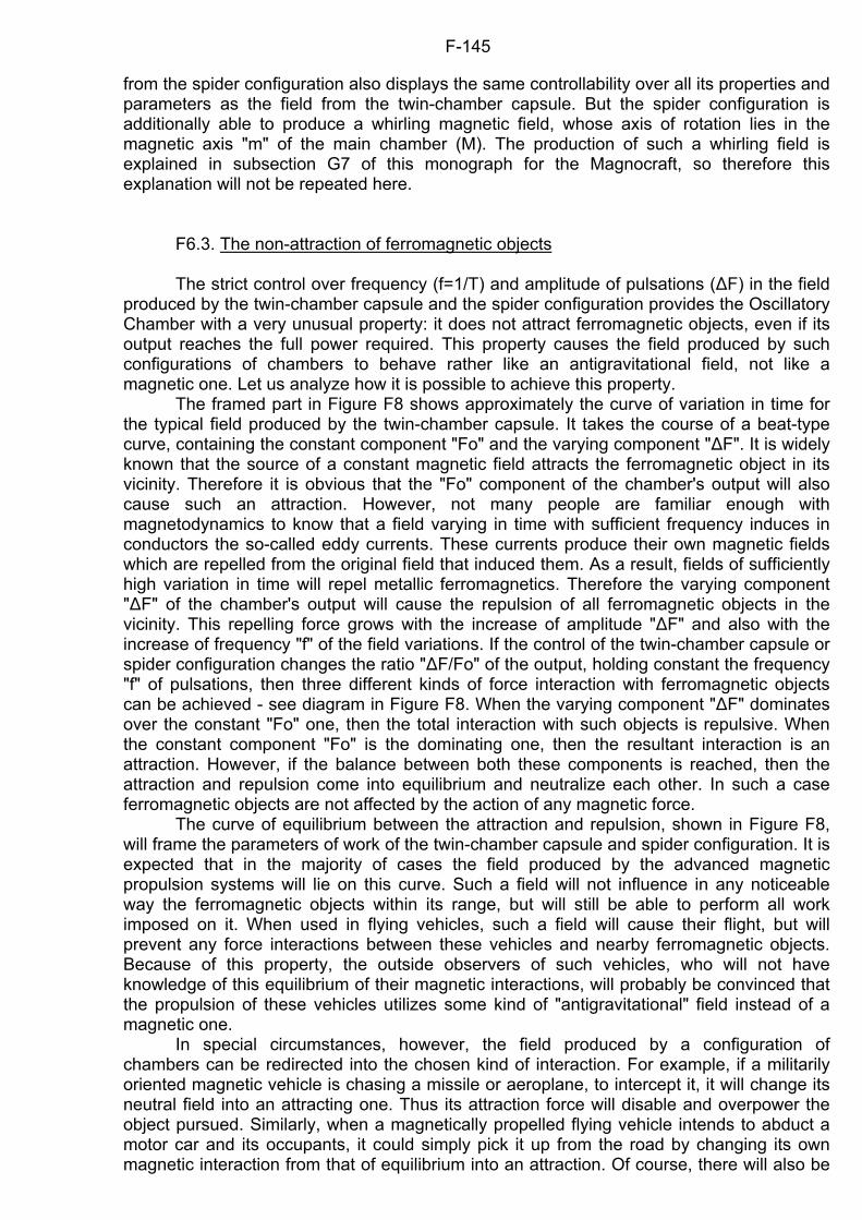
F-145
from the spider configuration also displays the same controllability over all its properties and parameters as the field from the twin-chamber capsule. But the spider configuration is additionally able to produce a whirling magnetic field, whose axis of rotation lies in the magnetic axis "m" of the main chamber (M). The production of such a whirling field is explained in subsection G7 of this monograph for the Magnocraft, so therefore this explanation will not be repeated here. F6.3. The non-attraction of ferromagnetic objects The strict control over frequency (f=1/T) and amplitude of pulsations ()F) in the field produced by the twin-chamber capsule and the spider configuration provides the Oscillatory Chamber with a very unusual property: it does not attract ferromagnetic objects, even if its output reaches the full power required. This property causes the field produced by such configurations of chambers to behave rather like an antigravitational field, not like a magnetic one. Let us analyze how it is possible to achieve this property. The framed part in Figure F8 shows approximately the curve of variation in time for the typical field produced by the twin-chamber capsule. It takes the course of a beat-type curve, containing the constant component "Fo" and the varying component ")F". It is widely known that the source of a constant magnetic field attracts the ferromagnetic object in its vicinity. Therefore it is obvious that the "Fo" component of the chamber's output will also cause such an attraction. However, not many people are familiar enough with magnetodynamics to know that a field varying in time with sufficient frequency induces in conductors the so-called eddy currents. These currents produce their own magnetic fields which are repelled from the original field that induced them. As a result, fields of sufficiently high variation in time will repel metallic ferromagnetics. Therefore the varying component ")F" of the chamber's output will cause the repulsion of all ferromagnetic objects in the vicinity. This repelling force grows with the increase of amplitude ")F" and also with the increase of frequency "f" of the field variations. If the control of the twin-chamber capsule or spider configuration changes the ratio ")F/Fo" of the output, holding constant the frequency "f" of pulsations, then three different kinds of force interaction with ferromagnetic objects can be achieved - see diagram in Figure F8. When the varying component ")F" dominates over the constant "Fo" one, then the total interaction with such objects is repulsive. When the constant component "Fo" is the dominating one, then the resultant interaction is an attraction. However, if the balance between both these components is reached, then the attraction and repulsion come into equilibrium and neutralize each other. In such a case ferromagnetic objects are not affected by the action of any magnetic force. The curve of equilibrium between the attraction and repulsion, shown in Figure F8, will frame the parameters of work of the twin-chamber capsule and spider configuration. It is expected that in the majority of cases the field produced by the advanced magnetic propulsion systems will lie on this curve. Such a field will not influence in any noticeable way the ferromagnetic objects within its range, but will still be able to perform all work imposed on it. When used in flying vehicles, such a field will cause their flight, but will prevent any force interactions between these vehicles and nearby ferromagnetic objects. Because of this property, the outside observers of such vehicles, who will not have knowledge of this equilibrium of their magnetic interactions, will probably be convinced that the propulsion of these vehicles utilizes some kind of "antigravitational" field instead of a magnetic one. In special circumstances, however, the field produced by a configuration of chambers can be redirected into the chosen kind of interaction. For example, if a militarily oriented magnetic vehicle is chasing a missile or aeroplane, to intercept it, it will change its neutral field into an attracting one. Thus its attraction force will disable and overpower the object pursued. Similarly, when a magnetically propelled flying vehicle intends to abduct a motor car and its occupants, it could simply pick it up from the road by changing its own magnetic interaction from that of equilibrium into an attraction. Of course, there will also be
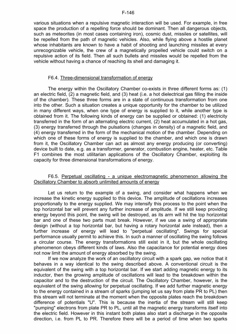
F-146
various situations when a repulsive magnetic interaction will be used. For example, in free space the production of a repelling force should be dominant. Then all dangerous objects, such as meteorites (in most cases containing iron), cosmic dust, missiles or satellites, will be repelled from the path of magnetic vehicles. Also, while flying above a hostile planet whose inhabitants are known to have a habit of shooting and launching missiles at every unrecognizable vehicle, the crew of a magnetically propelled vehicle could switch on a repulsive action of its field. Then all such bullets and missiles would be repelled from the vehicle without having a chance of reaching its shell and damaging it. F6.4. Three-dimensional transformation of energy The energy within the Oscillatory Chamber co-exists in three different forms as: (1) an electric field, (2) a magnetic field, and (3) heat (i.e. a hot dielectrical gas filling the inside of the chamber). These three forms are in a state of continuous transformation from one into the other. Such a situation creates a unique opportunity for the chamber to be utilized in many different ways, when one type of energy is supplied to it, while another type is obtained from it. The following kinds of energy can be supplied or obtained: (1) electricity transferred in the form of an alternating electric current, (2) heat accumulated in a hot gas, (3) energy transferred through the pulsations (changes in density) of a magnetic field, and (4) energy transferred in the form of the mechanical motion of the chamber. Depending on which one of these forms of energy is supplied to the chamber, and which one is drawn from it, the Oscillatory Chamber can act as almost any energy producing (or converting) device built to date, e.g. as a transformer, generator, combustion engine, heater, etc. Table F1 combines the most utilitarian applications of the Oscillatory Chamber, exploiting its capacity for three dimensional transformations of energy. F6.5. Perpetual oscillating - a unique electromagnetic phenomenon allowing the Oscillatory Chamber to absorb unlimited amounts of energy Let us return to the example of a swing, and consider what happens when we increase the kinetic energy supplied to this device. The amplitude of oscillations increases proportionally to the energy supplied. We may intensify this process to the point when the top horizontal bar will prevent any further increase of amplitude. If we still keep providing energy beyond this point, the swing will be destroyed, as its arm will hit the top horizontal bar and one of these two parts must break. However, if we use a swing of appropriate design (without a top horizontal bar, but having a rotary horizontal axle instead), then a further increase of energy will lead to "perpetual oscillating". Swings for special performance usually permit to achieve this. In such a manner of oscillating the swing follows a circular course. The energy transformations still exist in it, but the whole oscillating phenomenon obeys different kinds of laws. Also the capacitance for potential energy does not now limit the amount of energy absorbed by the swing. If we now analyze the work of an oscillatory circuit with a spark gap, we notice that it behaves in a way identical to the swing described above. A conventional circuit is the equivalent of the swing with a top horizontal bar. If we start adding magnetic energy to its inductor, then the growing amplitude of oscillations will lead to the breakdown within the capacitor and to the destruction of the circuit. The Oscillatory Chamber, however, is the equivalent of the swing allowing for perpetual oscillating. If we add further magnetic energy to the energy contained in a stream of sparks (jumping let us say from plate PR to PL) then this stream will not terminate at the moment when the opposite plates reach the breakdown difference of potentials "U". This is because the inertia of the stream will still keep "pumping" electrons from plate PR to PL, until all the magnetic energy transforms itself into the electric field. However in this instant both plates also start a discharge in the opposite direction, i.e. from PL to PR. Therefore there will be a period of time when two sparks
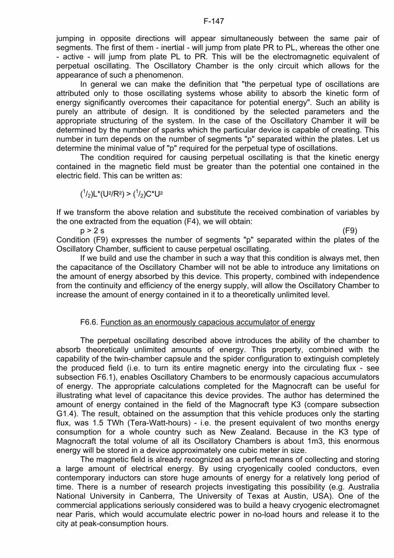
F-147
jumping in opposite directions will appear simultaneously between the same pair of segments. The first of them - inertial - will jump from plate PR to PL, whereas the other one - active - will jump from plate PL to PR. This will be the electromagnetic equivalent of perpetual oscillating. The Oscillatory Chamber is the only circuit which allows for the appearance of such a phenomenon. In general we can make the definition that "the perpetual type of oscillations are attributed only to those oscillating systems whose ability to absorb the kinetic form of energy significantly overcomes their capacitance for potential energy". Such an ability is purely an attribute of design. It is conditioned by the selected parameters and the appropriate structuring of the system. In the case of the Oscillatory Chamber it will be determined by the number of sparks which the particular device is capable of creating. This number in turn depends on the number of segments "p" separated within the plates. Let us determine the minimal value of "p" required for the perpetual type of oscillations. The condition required for causing perpetual oscillating is that the kinetic energy contained in the magnetic field must be greater than the potential one contained in the electric field. This can be written as:
(1/2)L*(U5/R5) > (1/2)C*U5 If we transform the above relation and substitute the received combination of variables by the one extracted from the equation (F4), we will obtain: p > 2 s (F9) Condition (F9) expresses the number of segments "p" separated within the plates of the Oscillatory Chamber, sufficient to cause perpetual oscillating. If we build and use the chamber in such a way that this condition is always met, then the capacitance of the Oscillatory Chamber will not be able to introduce any limitations on the amount of energy absorbed by this device. This property, combined with independence from the continuity and efficiency of the energy supply, will allow the Oscillatory Chamber to increase the amount of energy contained in it to a theoretically unlimited level. F6.6. Function as an enormously capacious accumulator of energy The perpetual oscillating described above introduces the ability of the chamber to absorb theoretically unlimited amounts of energy. This property, combined with the capability of the twin-chamber capsule and the spider configuration to extinguish completely the produced field (i.e. to turn its entire magnetic energy into the circulating flux - see subsection F6.1), enables Oscillatory Chambers to be enormously capacious accumulators of energy. The appropriate calculations completed for the Magnocraft can be useful for illustrating what level of capacitance this device provides. The author has determined the amount of energy contained in the field of the Magnocraft type K3 (compare subsection G1.4). The result, obtained on the assumption that this vehicle produces only the starting flux, was 1.5 TWh (Tera-Watt-hours) - i.e. the present equivalent of two months energy consumption for a whole country such as New Zealand. Because in the K3 type of Magnocraft the total volume of all its Oscillatory Chambers is about 1m3, this enormous energy will be stored in a device approximately one cubic meter in size. The magnetic field is already recognized as a perfect means of collecting and storing a large amount of electrical energy. By using cryogenically cooled conductors, even contemporary inductors can store huge amounts of energy for a relatively long period of time. There is a number of research projects investigating this possibility (e.g. Australia National University in Canberra, The University of Texas at Austin, USA). One of the commercial applications seriously considered was to build a heavy cryogenic electromagnet near Paris, which would accumulate electric power in no-load hours and release it to the city at peak-consumption hours.
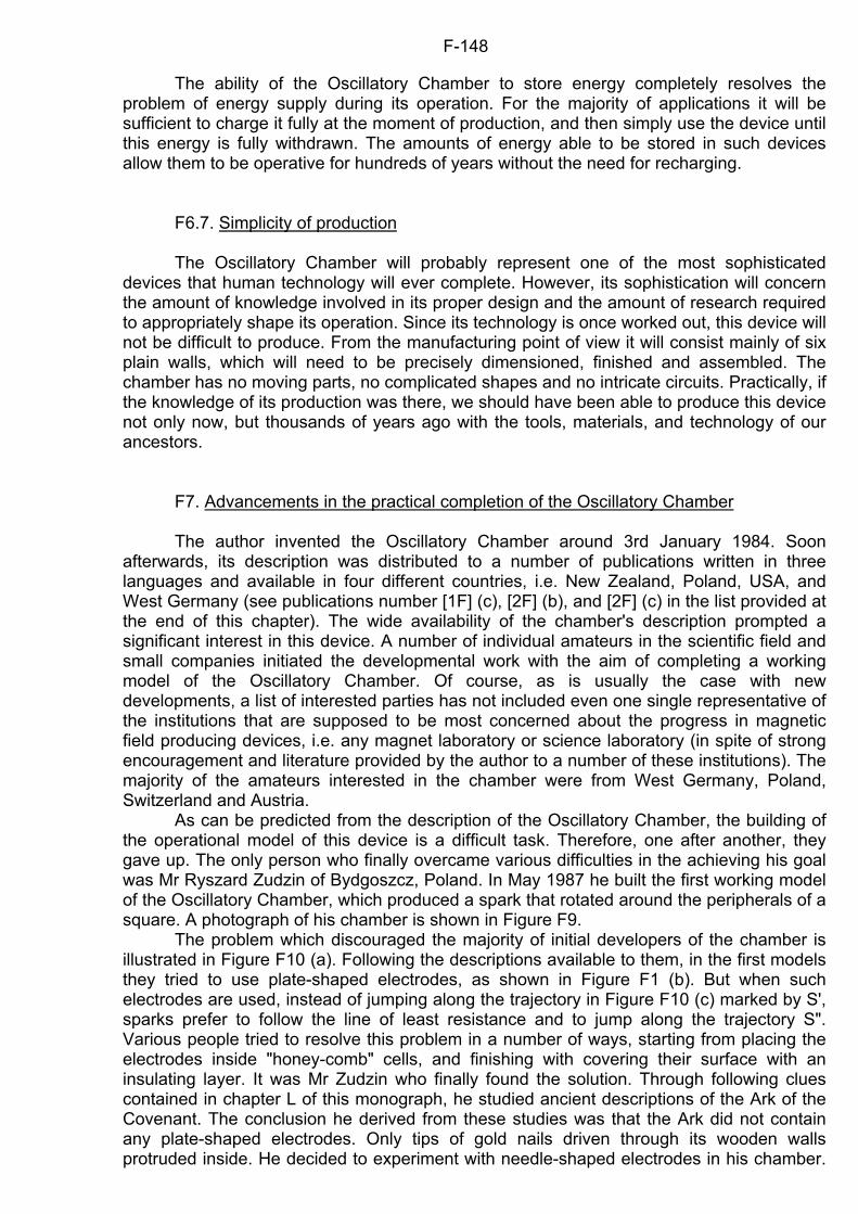
F-148
The ability of the Oscillatory Chamber to store energy completely resolves the problem of energy supply during its operation. For the majority of applications it will be sufficient to charge it fully at the moment of production, and then simply use the device until this energy is fully withdrawn. The amounts of energy able to be stored in such devices allow them to be operative for hundreds of years without the need for recharging. F6.7. Simplicity of production The Oscillatory Chamber will probably represent one of the most sophisticated devices that human technology will ever complete. However, its sophistication will concern the amount of knowledge involved in its proper design and the amount of research required to appropriately shape its operation. Since its technology is once worked out, this device will not be difficult to produce. From the manufacturing point of view it will consist mainly of six plain walls, which will need to be precisely dimensioned, finished and assembled. The chamber has no moving parts, no complicated shapes and no intricate circuits. Practically, if the knowledge of its production was there, we should have been able to produce this device not only now, but thousands of years ago with the tools, materials, and technology of our ancestors. F7. Advancements in the practical completion of the Oscillatory Chamber The author invented the Oscillatory Chamber around 3rd January 1984. Soon afterwards, its description was distributed to a number of publications written in three languages and available in four different countries, i.e. New Zealand, Poland, USA, and West Germany (see publications number [1F] (c), [2F] (b), and [2F] (c) in the list provided at the end of this chapter). The wide availability of the chamber's description prompted a significant interest in this device. A number of individual amateurs in the scientific field and small companies initiated the developmental work with the aim of completing a working model of the Oscillatory Chamber. Of course, as is usually the case with new developments, a list of interested parties has not included even one single representative of the institutions that are supposed to be most concerned about the progress in magnetic field producing devices, i.e. any magnet laboratory or science laboratory (in spite of strong encouragement and literature provided by the author to a number of these institutions). The majority of the amateurs interested in the chamber were from West Germany, Poland, Switzerland and Austria. As can be predicted from the description of the Oscillatory Chamber, the building of the operational model of this device is a difficult task. Therefore, one after another, they gave up. The only person who finally overcame various difficulties in the achieving his goal was Mr Ryszard Zudzin of Bydgoszcz, Poland. In May 1987 he built the first working model of the Oscillatory Chamber, which produced a spark that rotated around the peripherals of a square. A photograph of his chamber is shown in Figure F9. The problem which discouraged the majority of initial developers of the chamber is illustrated in Figure F10 (a). Following the descriptions available to them, in the first models they tried to use plate-shaped electrodes, as shown in Figure F1 (b). But when such electrodes are used, instead of jumping along the trajectory in Figure F10 (c) marked by S', sparks prefer to follow the line of least resistance and to jump along the trajectory S". Various people tried to resolve this problem in a number of ways, starting from placing the electrodes inside "honey-comb" cells, and finishing with covering their surface with an insulating layer. It was Mr Zudzin who finally found the solution. Through following clues contained in chapter L of this monograph, he studied ancient descriptions of the Ark of the Covenant. The conclusion he derived from these studies was that the Ark did not contain any plate-shaped electrodes. Only tips of gold nails driven through its wooden walls protruded inside. He decided to experiment with needle-shaped electrodes in his chamber.
F-149
And it turned out that it worked. Such needles repel sparks passing by, therefore these sparks are unable to take short cuts. In this way, the model of the Oscillatory Chamber which used the needle-shaped electrodes instead of plates - as shown in Figure F10 (b), was the first one which successfully produced sparks that rotate around peripherals of a square. This model also represents experimental proof that the principles of the Oscillatory Chamber are correct and that they can be implemented technologically in a working device. F7.1. Experimental devices The experience gained by Mr Zudzin during the completion of his device paves the way for the more advanced research on the development of the Oscillatory Chamber. For example, his research determined components of a laboratory station that should be set up to conduct experiments on the chamber. Such a station must include a minimum of four devices, i.e. (1) a chamber itself, (2) an electromagnet used to deflect path of sparks, (3) a measuring equipment, and (4) a power supply. The most important details on each of these are summarized below. (1) A chamber. Mr Zudzin's experience shows that the optimal shape and size for the experimental chamber is a cube with a side dimension of around 100 mm. Six walls of the chamber should be made of quartz plates, or - if quartz is unavailable - of a quartz glass. Gas used in the models of the Oscillatory Chamber built so far is just ordinary air under ambient pressure (the type of gas used will be important only at the more advanced, fine-tuning stage of the Chamber's development - see stage number 6 in next subsection). Electrodes in the Oscillatory Chamber need to be "needle-shaped", not plate-shaped, as was explained above. The latest experiments will try to apply needles which have tiny glass spheres inserted at their tips (the results of these experiments are not available yet). All electrodes placed along the same vertical column can be connected together electrically outside of the chamber. But subsequent columns of electrodes can not be connected horizontally by an external wire, because the current will pass through this wire (instead of jumping through the Chamber in the form of sparks). This means that each column of electrodes needs to be separately supplied with electric current (i.e. a system of switches needs to be used for the current supply). Of course, there is a simple solution to avoid the building of an expensive system of such switches that would supply current separately to each vertical column of electrodes. This is to supply with the current only one vertical column of electrodes for each wall of the chamber. (2) An electromagnet used to deflect sparks. During experiments the chamber must be placed between N and S poles of a strong electromagnet. The magnetic field produced by this electromagnet runs along the chamber's (m) axis and pushes all sparks toward the surface of the side walls. This push causes them to rotate in a clockwise (or counter-clockwise) direction. Without this initial magnetic field extended along the axis "m", the sparks would not rotate orderly around the chamber's peripherals, but rather jump chaotically in all possible directions. As the effectiveness of the chamber's operation will increase, this deflective function of the external magnetic field will gradually be taken over by a field produced by the chamber itself. (3) Measuring equipment. The sparks jumping through the Oscillatory Chamber are an extremely fast phenomenon which is almost impossible to be observed with the naked eye. For this reason the experimental station must include some measuring equipment, for example an oscilloscope, a built-in camera, magnetometers, thermometers, etc. (4) A power supply. The power source that Mr Zudzin used in his chamber is a high voltage impulse generator, similar to that used in electronic car ignition systems. It produces DC impulses, whose variation in time approximately follows a square curve. A diagram of his generator can be supplied on request. The voltage of his impulses was about 300 kV. The current was fed in fast pulses whose frequency tries to match the resonance frequency of the chamber.
F-150
It should be stressed at this point that the power supply to the chamber constitutes the most difficult and expensive part of the experimental station's set up. So far only Mr Zudzin has found enough dedication and persistence to continue his experimental work past this significant obstacle. Before building the successful DC impulses generator described above, Mr Zudzin built four different AC power systems, including a Tesla Coil, and various high voltage AC generators. But each of these AC systems proved to be unsuitable. For example, sparks produced by Tesla Coil seem to jump in uncontrollable directions and resist being put into any order. On the other hand, sparks from high voltage AC generators seem to keep open their ionic channels long after they diminish, so that the voltage can not build up on the electrodes. F7.2. Stages, goals, and ways of their achieving in the experimental building of the Oscillatory Chamber Because no research on this device has been done before, the major difficulty with the completion of the Oscillatory Chamber is that almost all of its details need to be discovered and worked out. The consequence of this is that the development of the chamber must be gradual, and according to a thoroughly designed master plan. It can be envisaged that the completion of a fully developed prototype of the Oscillatory Chamber must involve not less than nine separate stages, each one of which has a different goal and its own way of achieving this goal. These nine stages of the master plan are as follows: 1. The confirmation of the chamber's principles. The goal of this stage is to obtain the sparks that rotate around the perimeter of a cube, and in this way to prove that the principles of the Oscillatory Chamber can be implemented practically. Zudzin's prototype shown in Figure F9 has already achieved this goal. 2. The production of self-sustained oscillations. In the first stage it was determined how to produce a stream of sparks that continually rotates around the chamber's perimeter. But the jumping of these sparks were forced by the frequency of the external power supply, not by the chamber's own oscillations. Therefore, the goal for this second stage is to establish the method of increasing the amount of energy that is fed into the chamber and stored in it. Such a small reserve of energy in the chamber will cause it to self-sustain the jumping of its sparks for some time after the external power supply is terminated. The way of achieving this goal is by developing a technique for the experimental determination of the frequency of the chamber's own oscillations, and by subsequent synchronizing (with a slight phase shift - see subsection F6.1) the frequency of the external power supply to the frequency of the chamber's own oscillations. If this is achieved, the chamber must absorb and store a small amount of energy that will sustain the oscillations of its sparks after the external power supply is cut off. To simplify the task, it is possible to complete this stage with a chamber that has only a single oscillatory circuit. 3. A self-regulation of the sparks' phase shift. In both previous stages, to produce two streams of sparks jumping between two sets of opposite walls as many as two separate power supply devices needed to be used. But the properly designed chamber must work with the power supply to only one of its two oscillatory circuits (the second circuit should intake its energy from this first one). Therefore the goal of this stage is to alter the chamber's configuration (shape) in such a way that it will self-regulate and self-maintain two streams of sparks. These streams will be made to jump between both sets of opposite walls (i.e. both oscillatory circuits constituting the chamber) and their mutual phase shift will be self-maintained equal to 90 degrees. The way of achieving this goal is through introducing to the chamber's structure some additional features or elements, for example: insulated plates connected to each column of electrodes, which would overlap with the electrodes of the next walls, thus forming a capacitance between them (see Figure L6); cavities inside electrodes, similar to those forming stationary waves in microwave ovens; coils, similar to starter coils in electric motors; etc.
F-151
4. Making the chamber to absorb and store the amount of energy that suffices for the production of a useful magnetic field. There are two goals of this stage. The first is to significantly increase the time-span of the chamber sparks' rotation (i.e. to achieve streams of sparks which are self-oscillating for a long period of time). The second is to increase the strength of a magnetic field produced by the chamber, so that this field becomes sufficient to self-maintain the orderly rotation of the chamber's sparks (i.e. no external magnetic field will be needed any more to cause the sparks' rotation). Achieving both these goals requires: - to determine exactly the value of such phase shift between the frequency of the external power supply and the chamber's own (resonance) frequency, that this shift would make the chamber absorb energy from an external power supply and to store it; and - to apply practically the findings about this phase shift. To develop such a practical application of the results, three corresponding devices must be built. These are: (1) a chamber whose energy reserves are rechargeable, (2) a power supply device which is to co-operate with this chamber, and (3) an effective control device which will co-ordinate the recharging of the chamber by this power-supply device. 5. Controlling the chamber's period of pulsations. The goal of this stage is to learn how to control the chamber's period of pulsation through appropriate selection of pressure and composition of the dielectric gas contained in the chamber. To achieve this goal, a controlling device must be built, which, when added to the chamber's main structure, will allow for an effective control of its pulsations. 6. Releasing the phenomena that recover the heat dissipated by sparks (thus terminating the chamber's energy loses occurring during its operation). The goal of this stage is to alter the phenomena within the operational chamber in such a way that they will cause a conversion of energy contained in hot dielectric gas into the chamber's electric charge. To achieve this goal a complete understanding of the complex phenomena occurring in the chamber must be achieved, and then the alteration of this phenomena into a desired direction must be made. 7. Neutralization of electromagnetic forces that act on the chamber's structure. The goal of this stage is to find such mutual relationships between the design parameters of the chamber (i.e. its shape and dimensions) and the parameters of its work that the structure of the chamber will be released from the action of forces produced during its operation. The way of achieving this goal is to change parameters of the chamber's design and operation, and subsequently to monitor the influence these parameters have on the forces acting on the chamber's structure. Then the optimal parameters must be chosen, which will neutralize completely the action of these forces. 8. Building a twin-chamber capsule. The goal of this stage is to combine effectively two Oscillatory Chambers, so that they co-operate as a twin-chamber capsule. Achieving this goal involves various alterations to the control of both chambers, and also to the phenomena occurring within them, so that the final capsule can work effectively and remain fully controllable. 9. Unlimited increase of the chamber's energy reserves. The goal of this stage is to experimentally detect and eliminate all possible obstacles that could limit the amount of energy stored within twin-chamber capsules. The level which should be achieved at this stage is to store about 1.5 TWh (i.e. an equivalent of about 2 months of total energy consumption by a middle-sized country such as New Zealand) in a capsule of around 1 cubic meter. The achievement of this goal must involve various safety precautions, because Oscillatory Chambers which are heavily loaded with energy also represent powerful bombs whose accidental explosion would cause enormous destruction (see subsection M3). It is worth stressing here that after the completion of stage 4, the prototypes of the chamber become commercially useful and can successfully compete with electromagnets in various applications. Therefore, beginning with the 5th stage, the chamber becomes capable of earning money, thus it will pay for the further development itself. Also starting from stage 5, this device will quickly spread around the world and gradually take over numerous functions that presently are performed by various other devices (see subsection F9).
F-152
F7.3. The author's policy of the public ownership of the Oscillatory Chamber principles The practical completion of the Oscillatory Chamber requires advancement in two different areas which can be called (1) principles and (2) technology. In order to eliminate possible confusion as to what the difference between these two areas is, they will be explained here. Principles include the entire body of knowledge which explains how and why the chamber operates. Technology describes this specific knowledge that is required to actually build a working device (e.g. materials, manufacturing know-how, parameters of work, control devices, etc.). To illustrate the above with an example, subsections F1 to F6 of this chapter describe the chamber's principles, whereas subsection F7 is more concerned with the chamber's technology. From the moment of invention of the Oscillatory Chamber, the author adopted the policy that the principles of this device should be jointly owned by all the people living on Earth. In accordance with this policy, the inventor: (1) opposes patenting or imposing other restrictions concerning the ownership of the principles, (2) discloses and publishes the complete information about the chamber's principles, and (3) provides all the encouragement, advice, and expert assistance to every person, institution, or government who is interested in the development of this device. The reasoning behind this policy is as follows: (a) The chamber is a totally new idea which has no equivalent in any device that has been built so far (see subsection F9). (b) The completion of the chamber will constitute the most important milestone in the development of our civilization. It will advance this civilization from a planetary level into an interstellar level. (c) In the long term, access to the chamber will be important for the survival, well being, and further progress of our civilization. (d) The use of the chamber is the main requirement for rapid progress in many areas of science and technology in future, as well as the motivating force behind revolutionary changes needed in our energy management and productivity. (e) In future, the Oscillatory Chamber will become a main component of almost every other technological product (see subsection F9), including products that at present do not store any energy, such as household appliances, buildings, and even furniture. Thus the co-ownership and participation in its development guarantees everyone a personal contribution to the changing of practically every aspect of life of future generations. Contrary to the chamber's principles which should be owned by everyone, its technology should be owned exclusively by a country, institution, or individual who invested in this device. It is logical that the economic benefits resulting from the mastering of this technology should be reaped by those who undertake its developmental research. Of course it is not difficult to foresee that these benefits will be enormous. In order to protect the interests of the investors who will sponsor the technological research on the Oscillatory Chamber, the author has decided that beyond the 4th stage of the chamber's development, only the principles (but not the technological data) concerning this device will be published. Therefore all non-sponsoring institutions, who later have to catch up on this technology, will not only loose their markets because of starting too late, but also they will need to repeat the same costly research that the original developmental team has completed. The author realizes that the final development of the Oscillatory Chamber will require a team effort and the intellectual contribution from many minds. This in turn means that the last stages of the chamber's development would need to take the form of a quite large technological project. The project of course will require a number of research staff who must be well trained in solving the chamber's problems, and who should prove their capabilities in advance. It is well known that investigators who are completely new in a given field always require a significant period of studies (sometime even a few years) to
F-153
become familiar with the subject. During this time they remain intellectually non-productive. Thus in the case of beginning a project to build the Oscillatory Chamber, those people who already have done some experiments with the chamber will be invited first to take a part in the developmental team. Therefore, every person who at present is working on the chamber should keep in touch with the author, and should exchange systematically the information on their most recent achievements. Such contact and exchange of information also has some additional advantages, the most important of which are as follow: 1. The duplication of errors is avoided. Developmental research on the Oscillatory Chamber which is not coordinated by the author, will more likely lead to the duplication of the same errors by those individual investigators who do not know about each other's achievements. 2. A number of various aspects of the Oscillatory Chamber is investigated simultaneously. This in turn speeds up significantly the process of finding and implementing the correct technical solutions. 3. The contribution of fresh ideas is increased proportionally to the number of investigators simultaneously working on the Oscillatory Chamber. Subsequent investigators verify their ideas and contribute towards the common goal. As a result, the time-span in which this urgently needed invention is built (and used for the benefit of our civilization) is decreased. It should be mentioned here that such team work decreases also the secrecy about the advancement of the chamber's completion and thus gives everyone an equal opportunity to develop this device. This should prevent the history of the nuclear bomb from being repeated again. The military capabilities of the Oscillatory Chamber are so enormous (see subsections F9 and G13) that a totalitarian country or organization which secretly develops this device before anyone else could use it to conquer the world and to take complete control over our planet. F8. The energy conservation and energy production potentials of the Oscillatory Chamber When the Oscillatory Chamber is finally built, all its applications will be energy-related. This means that the chamber will affect every field of human activity which involves the production, distribution, transmission, conversion, and consumption of energy. Because of the unique properties of this device, the Oscillatory Chamber will be the catalyst of perfect energy management. Two factors will be significant for its implementation, i.e. totality and revolutionary impact. Totality will be manifested through the application of the chambers in every device, structure, or installation built by man. There will be no technological objects produced in future which will be devoid of some form of the Oscillatory Chamber. The revolutionary impact of the chamber will manifest itself through the type and extent of the changes that this device will introduce into our lives. After the full implementation of the chamber, Earth will be a completely different planet from what it is at present. The enormous transformations which the introduction of Oscillatory Chambers will cause on Earth can not happen instantaneously. It may take more than 40 years to complete the energy-related revolution initiated by putting these devices into use. Therefore, after the first Oscillatory Chamber is built, two different periods will be distinguishable in the utilization of this device, i.e. (1) the change-over period, and (2) the stable period. The change-over period will occur when the number of Oscillatory Chambers in use will gradually increase, but also traditional energy devices will be used in parallel with chambers. The stable period will occur when all the traditional energy devices will be eliminated and replaced by the chambers. It should be stressed that during the first period of the change-over, energy management on Earth will be described by different factors from those characterizing the second period of stable implementation of the chambers. To highlight these differences, the main attributes of both periods will be reviewed below.
F-154
F8.1. Characteristics of the first period (change-over) of the chamber's implementation The first, change-over, period of the chamber's utilization will take the character of a cumulative "energy revolution" extending from the time of the first introduction of this device until about 40 years afterwards. The characteristic attribute of this period will be that the Oscillatory Chamber will gain an increasing number of applications and gradually supersede (replace) all conventional energy devices. During the first half of this unstable period, energy demands will grow rapidly because the market will require more and more Oscillatory Chambers, all filled with energy. Therefore on top of the existing energy consumption will be added the accumulation of energy in the numerous, newly-built Oscillatory Chambers. The energy accumulated in them over this short period of time will later be consumed gradually, during entire decades or even centuries of the stable period of the chamber's utilization. In the second half of the change-over period, the energy demand will begin to decline, till it reaches the level characteristic for the stable period. The energy-related situation of our civilization during this change-over period can be described by the following factors: - The number of chambers used by each person will gradually increase. - Energy production must cover all the actual consumption and also its accumulation for future use in the numerous chambers. This will cause a rapid increase in energy prices. - The high energy prices will encourage the development and implementation of numerous new methods of energy production, based mainly on exploiting the unique properties of the Oscillatory Chamber. During the change-over period numerous free energy devices will be perfected, as well, various other "clean" energy sources will find a common use. The significant attribute of the change-over period will be an increase (not a decrease) in energy demand, causing the intensification of energy production, and intensification of the use of all energy resources. Because of the short duration of this period, it will have no significant impact on our total economy or overall standard of living. Also it will decline long before the Earth's energy resources are used up completely. But it may have significant bearing on the future of some individuals, companies, or even countries - mainly because it will make quick fortunes for the owners of energy resources and owners of energy production facilities. F8.2. Characteristics of energy management during the second, stable period of the Oscillatory Chamber's utilization About 40 years after the first Oscillatory Chamber is built, the use of this device will enter the second, stable period. In this period the energy-related situation of our civilization can be described by the following factors. - The number of chambers used by every person will reach such a level that the introduction of new ones will require the disposal of some of the old devices. - The energy production of our civilization will only need to cover the current energy consumption. - All basic applications of the chamber will be well recognized and implemented practically. There will be two main differences between the way energy will be managed in the period discussed and its management in present times. These are: (1) utilizing only "clean" methods of energy production, and (2) perfecting the efficiency of energy use. The high energy prices appearing in the first, change-over period of the chamber's utilization (see subsection F8.2) will promote the development of numerous methods of "clean" (i.e. non-polluting of the environment) energy production. In these methods two
F-155
unique properties of the Oscillatory Chamber will be employed. The first of them is the ability to intercept, total, and accumulate randomly appearing, small portions of energy. This will allow for a wide use of the energy sources at present recognized as too slow, too unpredictable, or too ineffective to be implemented commercially (e.g. sea waves and tides, day/night temperature changes, inertia of the ground, etc.). The second property of the chamber to be applied will be the production of a very powerful magnetic field. This field will open for the utilization as energy sources a number of phenomena which our present level of technology does not allow to be used for such a purpose, e.g. the magnetohydrodynamic effect of running water and wind, pulsating electromagnetic signals originating from natural sources such as crystals or free space, or a technological form of telekinesis used in the so-called free energy devices. Especially the possibility of the commercial utilization of free energy devices (which in this monograph are called telekinetic motors, generators, or powerstations - see description in subsections B6.2.2 and D6) may completely eliminate from further exploitation all our present fuel-based sources of energy. The increased efficiency of such "clean" methods of energy production resulting from the chamber's capabilities, in combination with an unlimited number of installations utilizing these methods, will make it possible for the entire energy demand of our civilization to be supplied from these non-polluting sources. The second main difference between the present management of energy and this one in the stable period of the chamber's utilization will be the drastic drop in energy consumption by our civilization. It is difficult to determine without detailed research how great this drop will be. But the analysis of its numerous causes allows one to estimate that the total energy demand at that period will be well below a quarter of the present consumption of energy and fuels. Such an enormous drop will be due to a number of reasons which are listed below: 1. The efficiency of all methods of energy production remaining in use at that time will be raised to perfection. These methods will allow to transform into energy and to store in the form of a magnetic field the entire work supplied to Oscillatory Chambers. Thus the present energy losses occurring during energy production will be eliminated. 2. Energy losses during distribution will be eliminated. The Oscillatory Chambers will be used as kind of "tins for energy". They will be loaded, or recharged, in the energy producing plants (or devices), from which these chambers will be delivered straight to their users. Therefore energy will be distributed in a different, free of losses manner - i.e. after being "packed" into the chambers (not like today, when it is transmitted through dissipating powerlines or inefficient transmission installations). 3. Energy losses during conversion will be eliminated. To achieve control over the performed work, the energy consumed is at present subjected to various transformations, usually involving significant dissipation (e.g. the gearbox needed to transform a car's mechanical energy). The utilization of the Oscillatory Chambers will remove such transformations, as the direct output from these chambers will be the work which users want to be done (e.g. future models of cars will have chambers installed directly in their wheels). Therefore, all controlling activities required for the adjustment of work just being performed will be conducted inside the chambers, causing no energy loss at all. 4. The efficiency of energy consumption will be perfected. At present only a small fraction of energy released by our engines is converted into useful work. Most of our fuel is now wasted and pollutes the environment. Using the Oscillatory Chambers will ensure the conversion into useful work of almost the entire energy supply contained in them. 5. The energy flow will be reversible. At "braking" stages of machines' operation, the magnetic field will allow energy to flow back into the chamber. The principle of this flow will be identical to that of some electric motors which, when provided with motion, turn themselves into generators and produce electricity (instead of consuming it). This principle will allow for the elimination of energy losses during the idle running of machines; for inertia; during accelerating and decelerating of masses, etc. In this way a large proportion of energy that gets wasted at present will be recoverable after the introduction of Oscillatory Chambers.
F-156
6. Energy will not be disposable. Once accumulated within a chamber it will be used entirely. The energy from the old chambers designated for disposal will be transferred into new ones and then consumed. The destruction of chambers still containing energy will not only be uneconomical, but also extremely dangerous (see subsection M3). 7. Energy consumption in civil engineering work will be eliminated. The introduction of magnetic propulsion will completely remove all work connected with building and maintaining roads, railways, bridges, ports, streets, etc. All transport and travel will be done by means of soaring in space, so these civil constructions will not be required any more. 8. Energy consumption in the transport of raw materials, ore and minerals will be eliminated. A significant decrease in the weight and complexity of all machines, caused by the application of the Oscillatory Chambers, will allow us to build resource-processing factories as a system of flying modules. These modules will approach the location of the resources in order to process them. In this way more than half of our present industries could be organized as "flying factories", e.g. all food-processing industry, mining and processing of minerals, a large part of energy production, farming, harvesting, forestry, etc. The homes of people employed in these factories will also be built in the form of flying vehicles. 9. Much of the present means of transport for people will be eliminated. At the moment people need to move frequently, travelling from home to the work place, to shopping centres, schools, holiday resorts, etc. When magnetic propulsion becomes a reality, homes and flats will be provided with propulsors and built in the form of flying vehicles. They will be able to land one on top of the other, forming types of modular skyscrapers (see the configurations formed by the Magnocraft - subsection G5). So there will be no need for present forms of travel, because these homes will "park" near the place where their owners need to spend time. F9. Future applications of the Oscillatory Chamber To-date there does not exist any other technical invention which has altered the state of our technical environment to the same extent as the completion of the Oscillatory Chamber will do. The impact this device will have on the materialistic aspects of human life can be compared only to the effect of the introduction of computers in the intellectual sphere. One can predict that by the year 2084 (i.e. in one hundred years after the chamber's discovery) almost every active device used by people will consist of some form of the Oscillatory Chamber. Many structures which at present are passive, such as furniture, buildings, monuments, etc., will be transformed by the Oscillatory Chamber into active ones, i.e. moving, altering orientation and adjusting their location to the changing requirements of their users. Let us briefly review the main applications of the Oscillatory Chamber, trying to forecast what impact they will have on particular fields of human activity. The unique advantages of the Oscillatory Chambers will result in this device completely taking over the present functions of electromagnets. Research laboratories, capable of using magnetic fields of strengths unattainable today, will be able to wrest a number of secrets from nature, introducing a significant step forward in our science and technology. Industry, utilizing technologies that are based on the application of super-strong magnetic fields, will provide us with a number of products of as yet unattainable quality. For example, we could produce indestructible rubber and clothes, objects made completely of monocrystals, concrete stronger than steel, etc. Also a new type of material, suiting the magnetic requirements of the Oscillatory Chamber, will supersede those in use at present. The Oscillatory Chamber will eliminate not only the electromagnets used as separate devices, but also all those which make up parts of other devices, e.g. from electric motors, electricity generators, etc. Advantages of the chamber, such as: high power-to-dimensions ratio, ability to introduce long gaps between the time of energy supply and the time of energy consumption, controllability; will result in the wide application of this
F-157
device for building light vehicles, pumps and generators working far from an energy supply and civilization centers, ship and aeroplane engines, medical instruments, etc. The twin-chamber capsule providing a constant magnetic field will replace some present-day permanent magnets. Therefore future models of our speakers, bearings, clutches, grapples, rails, etc., will all employ Oscillatory Chambers. The numerous applications of the chamber in the future are connected with the ability to store huge amounts of energy. To have an idea of what kind of potentials are involved here, it is enough to realize that the energy needs for today's factories, towns, big ships or aeroplanes can be satisfied by a chamber of pin-head size. All present batteries, accumulators and electricity transmission lines (power lines) will be replaced by light, much more efficient, and rechargeable Oscillatory Chambers. Built as twin-chamber capsules, they will not yield any magnetic field when used for energy storage. A wide application of the chamber can also be predicted in all cases where the transformation of energy is required - compare with Table F1. Such devices as telekinetic generators of free energy (described in subsections B6.2.2 and D6) and generators of clean energy (exploiting solar radiation, wind, ocean waves, tides), engines, air conditioners, etc.; can become very efficient when employing the principles of the Oscillatory Chamber. The transformation of energy will also replace today's transformation of motion. Future mechanisms will be much simpler and lighter, because they will be released from all the devices which presently provide and transform motion. The motion will be created in the location where the work is to be done and in the exact form that is required. For example if a future hobbyist were to build a copy of our present car, he would produce the motion right inside the wheels, therefore the whole engine, gears, and transmission would be eliminated. The Oscillatory Chambers will also introduce a completely new fashion, which at present has no appropriate technical back-up. It will be the fashion to suspend objects in space. It should be expected that future furniture, household devices, machines, and even buildings or elements of architecture will hang in space, supported by the invisible force lines of a magnetic field. One of the consequences of this fashion will be the complete disappearance of the wheel, as all present rolling movements will be replaced by soaring in space. Enormous potential is involved in the military applications of the chamber. A system of these devices producing whirling magnetic fields will be able to form barriers and mine fields which in seconds may explosively vaporize every object made of a good electric conductor, entering into their range. Missiles containing systems of chambers may cause instant evaporation of huge constructions made of steel, such as bridges, factories, ships, aeroplanes, rockets, satellites, etc. The rapid release of the energy stored within a chamber (e.g. through its detonation - see [5F]) will cause an explosion comparable in effects to the use of a nuclear bomb. The only difference will be that the chamber will not pollute the environment by any radioactivity. Military vehicles, whose chambers will form repulsive or attractive interactions with ferromagnetic objects in their vicinity (see Figure F8), will be able to repel, or to attract and intercept, vehicles or missiles on the opposite side. The most promising prospects, however, are connected with use of the Oscillatory Chamber for the purpose for which its principle was originally invented - i.e. for the magnetic propulsion of flying vehicles. The next chapters of this monograph are devoted to the description of such applications of the chamber. F10. Monographs describing the Magnocraft, the Oscillatory Chamber and other corresponding devices Since the Magnocraft and the Oscillatory Chamber were invented, the author has prepared and disseminated a number of monographs devoted to the presentation of these devices. The most important of these are listed below in the order of their completion.
F-158
[1F] "Theory of the Magnocraft". Monograph by the author. It contained the first comprehensive presentation of the Magnocraft, including a brief account (one chapter) dedicated to the Oscillatory Chamber representing the "engine" for this vehicle. One chapter was also dedicated to the description of Magnetic Personal Propulsion. The monograph [1F] was published in the following editions: (a) First New Zealand edition, January 1984, ISBN 0-9597698-0-3; (b) First USA edition - co-published in USA by: Energy Unlimited, PO Box 35637 Sta. D, Albuquerque, NM 78176, June 1985. (c) First Polish edition (written in Polish language) entitled, "Teoria Magnokraftu", March 1986, ISBN 0-9597698-5-4. (d) Second New Zealand edition - extended, Invercargill, August 1984, ISBN 0-9597698-1-1. [2F] "The Oscillatory Chamber - a breakthrough in the principles of magnetic field production". Monograph by the author. It was intended to provide the first complete disclosure of the Oscillatory Chamber, prepared as a proposal to be discussed and evaluated by other scientists. One chapter was dedicated to the Magnocraft. The monograph [2F] was published in the following editions: (a) First New Zealand Edition, December 1984, ISBN 0-9597698-2-X. (b) First USA edition, published in the "Energy Unlimited" magazine, Issue 19/1985, pages 15 to 43. This special edition of the magazine (published by "Energy Unlimited", PO Box 35637, Station D, Albuquerque, NM 87176, USA) reprinted the whole monograph on the Oscillatory Chamber. (c) First West German edition (written in German language) entitled, "Die 'Schwingkammer' Energie & Antrieb fur das Weltraumzeitalter", published by: Raum & Zeit Verlag, Dammtor 6, D-3007 Gehrden, West Germany; June 1985, ISBN 3-89005-006-9. (d) Second New Zealand edition, augmented, Invercargill, October 1985, ISBN 0-9597698-4-6. This edition contained the first presentation of the Concept of Dipolar Gravity. [3F] "The Magnocraft: a saucer-shaped space vehicle propelled by a pulsating magnetic field". Monograph, Invercargill, New Zealand, September 1986, ISBN 0-9597698-3-8. This monograph represented a newly updated and extended version of the monograph [1F]. It was composed of three parts: (1) the philosophical foundations, including the Concept of Dipolar Gravity, (2) Theory of the Magnocraft, and (3) the validation of theories and devices proposed in parts 1 & 2 (proving that "UFOs are already operational Magnocraft"). [4F] "The Magnocraft - Earth's version of a UFO". Dunedin - New Zealand, 1989, ISBN 0-9597698-6-2, a private edition by the author (500 pages). It contains an augmented and updated version of the descriptions from monograph [3F]. [5F] "Tapanui Cataclysm - an explanation for the mysterious explosion in Otago, New Zealand, 1178 A.D.". Dunedin, New Zealand, 1989, ISBN 0-9597698-7-0, a private edition by the author (52 pages). It presents the author's findings about a crater formed when Magnocraft-like vehicles exploded near Tapanui (see subsection M3). [6F] "The magnetic extraction of energy from the environment". Dunedin, New Zealand, 1990, ISBN 0-9597946-1-1, a private edition by the author. It describes free energy devices that utilize the "Telekinetic Effect" released through acceleration or deceleration of magnetic fields (see subsection B6.2).
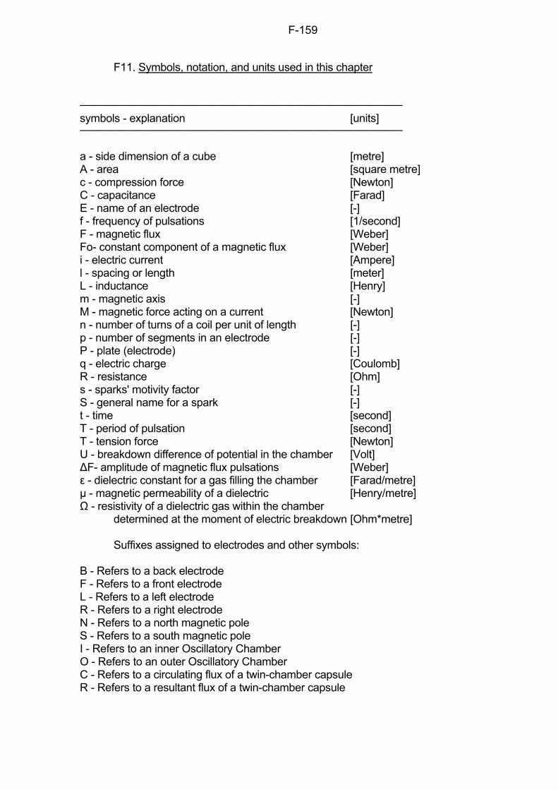
F-159
F11. Symbols, notation, and units used in this chapter symbols - explanation [units] a - side dimension of a cube [metre] A - area [square metre] c - compression force [Newton] C - capacitance [Farad] E - name of an electrode [-] f - frequency of pulsations [1/second] F - magnetic flux [Weber] Fo- constant component of a magnetic flux [Weber] i - electric current [Ampere] l - spacing or length [meter] L - inductance [Henry] m - magnetic axis [-] M - magnetic force acting on a current [Newton] n - number of turns of a coil per unit of length [-] p - number of segments in an electrode [-] P - plate (electrode) [-] q - electric charge [Coulomb] R - resistance [Ohm] s - sparks' motivity factor [-] S - general name for a spark [-] t - time [second] T - period of pulsation [second] T - tension force [Newton] U - breakdown difference of potential in the chamber [Volt] ∆F- amplitude of magnetic flux pulsations [Weber] ε - dielectric constant for a gas filling the chamber [Farad/metre] µ - magnetic permeability of a dielectric [Henry/metre] Ω - resistivity of a dielectric gas within the chamber determined at the moment of electric breakdown [Ohm*metre] Suffixes assigned to electrodes and other symbols: B - Refers to a back electrode F - Refers to a front electrode L - Refers to a left electrode R - Refers to a right electrode N - Refers to a north magnetic pole S - Refers to a south magnetic pole I - Refers to an inner Oscillatory Chamber O - Refers to an outer Oscillatory Chamber C - Refers to a circulating flux of a twin-chamber capsule R - Refers to a resultant flux of a twin-chamber capsule
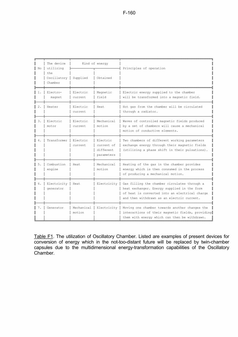
F-160
The device Kind of energy
No utilizing Principles of operation
the
Oscillatory Supplied Obtained
Chamber
1. Electro- Electric Magnetic Electric energy supplied to the chamber
magnet current field will be transformed into a magnetic field.
2. Heater Electric Heat Hot gas from the chamber will be circulated
current through a radiator.
3. Electric Electric Mechanical Waves of controlled magnetic fields produced
motor current motion by a set of chambers will cause a mechanical
motion of conductive elements.
4. Transformer Electric Electric Two chambers of different working parameters
current current of exchange energy through their magnetic fields
different (utilizing a phase shift in their pulsations).
parameters
5. Combustion Heat Mechanical Heating of the gas in the chamber provides
engine motion energy which is then consumed in the process
of producing a mechanical motion.
6. Electricity Heat Electricity Gas filling the chamber circulates through a
generator heat exchanger. Energy supplied in the form
of heat is converted into an electrical charge
and then withdrawn as an electric current.
7. Generator Mechanical Electricity Moving one chamber towards another changes the
motion interactions of their magnetic fields, providing
them with energy which can then be withdrawn.
Table F1. The utilization of Oscillatory Chamber. Listed are examples of present devices for conversion of energy which in the not-too-distant future will be replaced by twin-chamber capsules due to the multidimensional energy-transformation capabilities of the Oscillatory Chamber.
F-161
Fig. F1. The transformation of an oscillatory circuit with a spark gap into an Oscillatory Chamber. (a) The conventional form of an oscillatory circuit with a spark gap, as it was discovered by J. Henry in 1845. Its three vital elements (i.e. capacitance "C1", inductance "L" and spark gap "E") are provided by separate devices. (b) The modified version of the oscillatory circuit with a spark gap. All three vital elements are concentrated in one device, i.e. a set of conductive segments "1, 2, ..., p" forming two plates "PF" and "PB" joined to the inner surfaces of the two opposite walls of a cubical chamber made of an electric insulator. The side dimension of the cube is marked by "a". (c) The Oscillatory Chamber formed by combining together two modified oscillatory circuits "C1" and "C2" identical to that presented in part (b) of this diagram. The consecutive appearance of sparks "Sr-l", "Sf-b", "Sl-r", "Sb-f" oscillating along the surface of the walls creates a kind of electric arc circulating around the inner perimeter of this chamber and producing a strong magnetic field.
F-162
Fig. F2. The assumed appearance of the Oscillatory Chamber. It will look like a glass cube. Streaks of bright shimmering sparks of golden colour will run horizontally around the inner surfaces of it's side walls. These sparks will slowly move their plots like a knot of snakes writhing around their prey. Therefore the operational chamber will give an impression of a living creature preoccupied with some mysterious activity. The broken lines indicate the column of produced magnetic field distributed along the "m" axis. When viewed from the direction perpendicular to the magnetic field force lines (i.e. exactly as it is illustrated in the above diagram) this column will trap the light and thus it should be seen by the naked eye as a black bar extended in both directions from the chamber - see the description of such bars presented in subsection G5.4. Also this field should cause the inside of the chamber to be non-transparent. Therefore the chamber should look as if it is filled with black smoke. If viewed along the magnetic field force lines, the passage through the chamber should be transparent, except for the cases presented in Figure F5.
F-163
Fig. F3. The mechanism of mutual neutralization of the electro-magnetic forces, simultaneously tensing and compressing the Oscillatory Chamber in opposite directions. (a) The four basic phases of operation of the Oscillatory Chamber. Symbols: R, L, F, B - the right, left, front and back plates of the chamber that together form two co-operating oscillatory circuits; Sr-l, Sf-b, Sl-r, Sb-f - the four streams of electric sparks that appear in succession during a single cycle of oscillations, thus forming one complete rotation of the square arc. (b) The changes in the potential of the plates during a full cycle of the chamber's operation. Symbols: T - period of pulsation; t - time; +q, -q - positive and negative electric charges accumulated on plates. (c) The changes in the electro-magnetic containment forces (M) acting on particular electric sparks. (d) The changes in the tensing forces (T) and the compressing forces (C) that mutually neutralize each other. The tensing forces (T) are produced by the electro-magnetic containment interactions occurring between the sparks and the magnetic field that fills the chamber. The compressing forces (C) are caused by the reciprocal Coulombs attraction of the opposite electric charges accumulated on the facing plates. Note that both groups of these forces have a symmetrical course but opposite value. This is why they cancel each other's action.
F-164
Fig. F4. A basic arrangement of two Oscillatory Chambers called the "twin-chamber capsule". The main application of this capsule is to constitute a propulsor for the Magnocraft. The twin-chamber capsule is formed from two oppositely oriented chambers placed one inside the other. Because of the need for free floating of the inner (I) chamber suspended inside of the outer (O) one, the side edges "a" of both Oscillatory Chambers must meet the equation: ao= 3·ai (see equation G9). The resultant magnetic flux (R) yield to the environment from these arrangements is obtained as a difference between outputs from chambers having opposite orientation of poles. The principles of forming this resultant flux are illustrated in Figure F6. The twin-chamber capsule allows full control over all the attributes of the produced magnetic field. The subjects of control are the following properties of the resultant flux (R): (1) strength of the field (fluently controlled from zero to maximum), (2) frequency of pulsations, (3) ratio of the amplitude of the field's pulsations to its constant component ( F/Fo - see Figure F8), (4) character of the field (i.e. constant, pulsating, alternating), (5) variation in time (i.e. linear, sinusoidal, beat-type curves), (6) polarity (i.e. from whichever side of the arrangement the N and S poles prevail). Symbols: O - outer chamber, I - inner chamber, C - circulating flux trapped inside the capsule, R - resultant flux yield from the capsule to the environment.
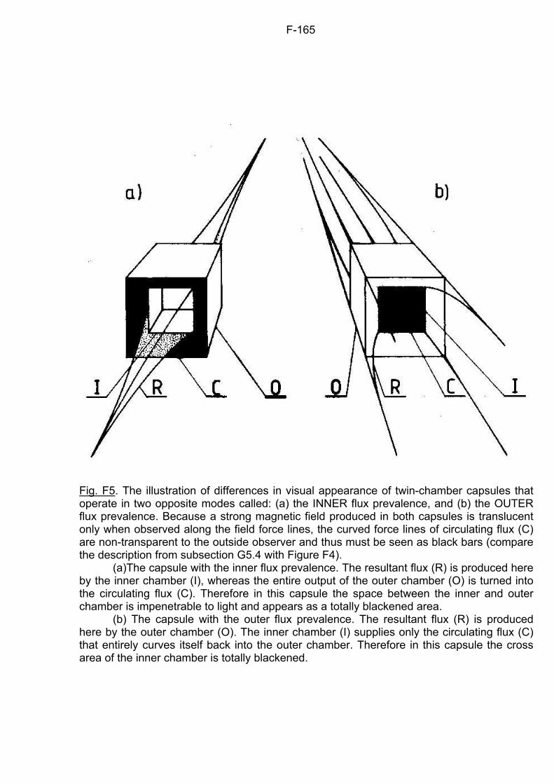
F-165
Fig. F5. The illustration of differences in visual appearance of twin-chamber capsules that operate in two opposite modes called: (a) the INNER flux prevalence, and (b) the OUTER flux prevalence. Because a strong magnetic field produced in both capsules is translucent only when observed along the field force lines, the curved force lines of circulating flux (C) are non-transparent to the outside observer and thus must be seen as black bars (compare the description from subsection G5.4 with Figure F4). (a)The capsule with the inner flux prevalence. The resultant flux (R) is produced here by the inner chamber (I), whereas the entire output of the outer chamber (O) is turned into the circulating flux (C). Therefore in this capsule the space between the inner and outer chamber is impenetrable to light and appears as a totally blackened area. (b) The capsule with the outer flux prevalence. The resultant flux (R) is produced here by the outer chamber (O). The inner chamber (I) supplies only the circulating flux (C) that entirely curves itself back into the outer chamber. Therefore in this capsule the cross area of the inner chamber is totally blackened.
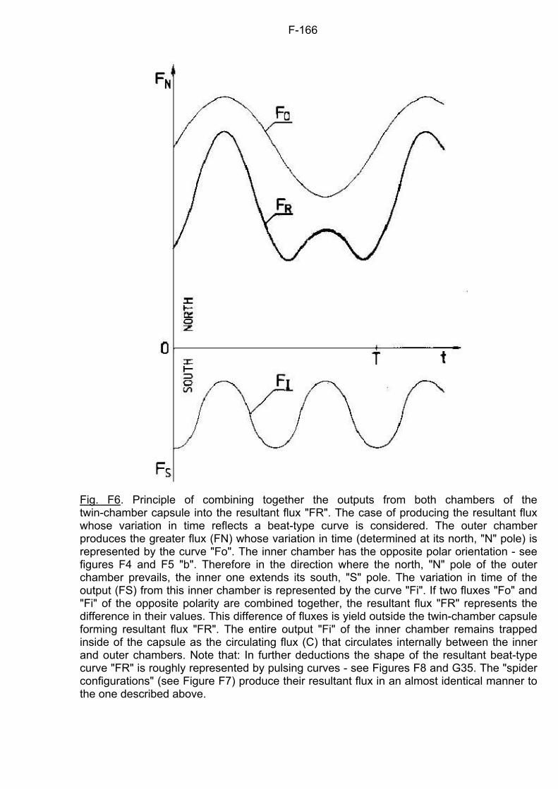
F-166
Fig. F6. Principle of combining together the outputs from both chambers of the twin-chamber capsule into the resultant flux "FR". The case of producing the resultant flux whose variation in time reflects a beat-type curve is considered. The outer chamber produces the greater flux (FN) whose variation in time (determined at its north, "N" pole) is represented by the curve "Fo". The inner chamber has the opposite polar orientation - see figures F4 and F5 "b". Therefore in the direction where the north, "N" pole of the outer chamber prevails, the inner one extends its south, "S" pole. The variation in time of the output (FS) from this inner chamber is represented by the curve "Fi". If two fluxes "Fo" and "Fi" of the opposite polarity are combined together, the resultant flux "FR" represents the difference in their values. This difference of fluxes is yield outside the twin-chamber capsule forming resultant flux "FR". The entire output "Fi" of the inner chamber remains trapped inside of the capsule as the circulating flux (C) that circulates internally between the inner and outer chambers. Note that: In further deductions the shape of the resultant beat-type curve "FR" is roughly represented by pulsing curves - see Figures F8 and G35. The "spider configurations" (see Figure F7) produce their resultant flux in an almost identical manner to the one described above.
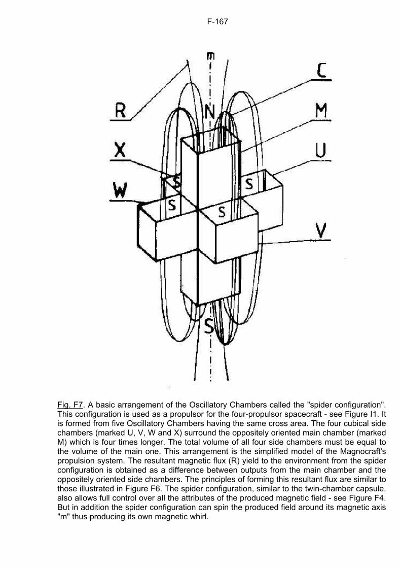
F-167
Fig. F7. A basic arrangement of the Oscillatory Chambers called the "spider configuration". This configuration is used as a propulsor for the four-propulsor spacecraft - see Figure I1. It is formed from five Oscillatory Chambers having the same cross area. The four cubical side chambers (marked U, V, W and X) surround the oppositely oriented main chamber (marked M) which is four times longer. The total volume of all four side chambers must be equal to the volume of the main one. This arrangement is the simplified model of the Magnocraft's propulsion system. The resultant magnetic flux (R) yield to the environment from the spider configuration is obtained as a difference between outputs from the main chamber and the oppositely oriented side chambers. The principles of forming this resultant flux are similar to those illustrated in Figure F6. The spider configuration, similar to the twin-chamber capsule, also allows full control over all the attributes of the produced magnetic field - see Figure F4. But in addition the spider configuration can spin the produced field around its magnetic axis "m" thus producing its own magnetic whirl.
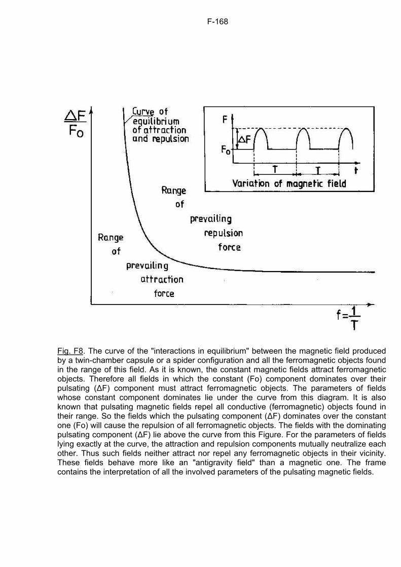
F-168
Fig. F8. The curve of the "interactions in equilibrium" between the magnetic field produced by a twin-chamber capsule or a spider configuration and all the ferromagnetic objects found in the range of this field. As it is known, the constant magnetic fields attract ferromagnetic objects. Therefore all fields in which the constant (Fo) component dominates over their pulsating ()F) component must attract ferromagnetic objects. The parameters of fields whose constant component dominates lie under the curve from this diagram. It is also known that pulsating magnetic fields repel all conductive (ferromagnetic) objects found in their range. So the fields which the pulsating component ()F) dominates over the constant one (Fo) will cause the repulsion of all ferromagnetic objects. The fields with the dominating pulsating component ()F) lie above the curve from this Figure. For the parameters of fields lying exactly at the curve, the attraction and repulsion components mutually neutralize each other. Thus such fields neither attract nor repel any ferromagnetic objects in their vicinity. These fields behave more like an "antigravity field" than a magnetic one. The frame contains the interpretation of all the involved parameters of the pulsating magnetic fields.
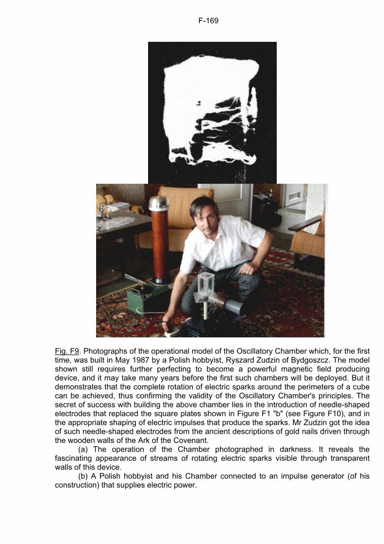
F-169
Fig. F9. Photographs of the operational model of the Oscillatory Chamber which, for the first time, was built in May 1987 by a Polish hobbyist, Ryszard Zudzin of Bydgoszcz. The model shown still requires further perfecting to become a powerful magnetic field producing device, and it may take many years before the first such chambers will be deployed. But it demonstrates that the complete rotation of electric sparks around the perimeters of a cube can be achieved, thus confirming the validity of the Oscillatory Chamber's principles. The secret of success with building the above chamber lies in the introduction of needle-shaped electrodes that replaced the square plates shown in Figure F1 "b" (see Figure F10), and in the appropriate shaping of electric impulses that produce the sparks. Mr Zudzin got the idea of such needle-shaped electrodes from the ancient descriptions of gold nails driven through the wooden walls of the Ark of the Covenant. (a) The operation of the Chamber photographed in darkness. It reveals the fascinating appearance of streams of rotating electric sparks visible through transparent walls of this device. (b) A Polish hobbyist and his Chamber connected to an impulse generator (of his construction) that supplies electric power.
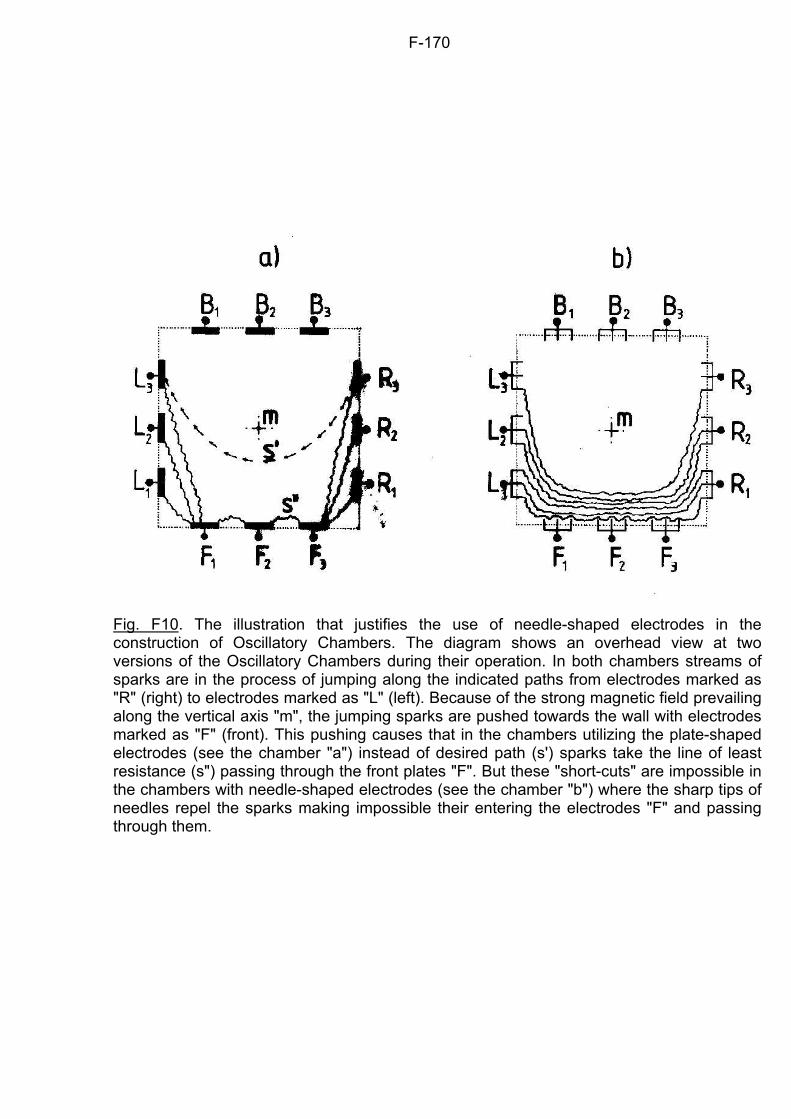
F-170
Fig. F10. The illustration that justifies the use of needle-shaped electrodes in the construction of Oscillatory Chambers. The diagram shows an overhead view at two versions of the Oscillatory Chambers during their operation. In both chambers streams of sparks are in the process of jumping along the indicated paths from electrodes marked as "R" (right) to electrodes marked as "L" (left). Because of the strong magnetic field prevailing along the vertical axis "m", the jumping sparks are pushed towards the wall with electrodes marked as "F" (front). This pushing causes that in the chambers utilizing the plate-shaped electrodes (see the chamber "a") instead of desired path (s') sparks take the line of least resistance (s") passing through the front plates "F". But these "short-cuts" are impossible in the chambers with needle-shaped electrodes (see the chamber "b") where the sharp tips of needles repel the sparks making impossible their entering the electrodes "F" and passing through them.
G-171
Chapter G:
THE MAGNOCRAFT The "Magnocraft" is the name given to a completely new type of space vehicle, which is propelled by a pulsating magnetic field. The main goal to be achieved through the invention of this vehicle is to obtain such a design for an interstellar spaceship that would make it possible for it to be completed by a small country, or even by a large industrial corporation. How close we are to achieving this goal is demonstrated in the analysis of the attributes of the Magnocraft listed below: 1. Not a single moving part is necessary, either for the flight or the manoeuvring of this spacecraft. (Theoretically speaking, the whole Magnocraft can be produced like a plastic balloon, i.e. from only one part. In comparison, the new Boeing 747 - 400 "Jumbo Jet" contains about four million individual parts.) Some versions of the Magnocraft (usually miniature, computer-operated probes) will in fact be built devoid of even a single moving part, and at the same time will perform all their required functions excellently. In the case of large, man-operated versions, moving parts, such as doors, will be included only for the convenience of the crew. How important a technological break-through this attribute of the Magnocraft is can be realized when we think of the production of all these millions of co-operating parts contained in space vehicles to date, and consider the consequences of the failure to move any of these parts somewhere in space. 2. The energy resources within the Magnocraft are self-rechargeable. When this spaceship accelerates it consumes the energy contained in its magnetic field, but when it decelerates the energy is returned back to the field. The principles of such self-recharging are the same as those involved in the return of electricity to the aerial overhead powerline by an electric train decelerating its speed by turning its motors into generators. Therefore, if the Magnocraft returns from a round trip in free space (where the flight does not involve any friction) its energy resources will be the same as they were at the moment of the start of the voyage. In effect, magnetic propulsion will allow this vehicle to travel unlimited distances, because - contrary to our rockets - its material and energy resources will never be exhausted. The self-rechargeability of the Magnocraft means that all countries which don't have their own energy resources or whose energy resources are close to exhaustion should be vitally interested in obtaining access to this vehicle. 3. The specifications for this spacecraft are at such an advanced level that it can not be compared with any other device that has been built to-date. For example, the Magnocraft is able to produce: (a) A rotating "plasma saw" which is obtained from the surrounding medium by ionizing and swirling it with the vehicle's powerful "magnetic whirl". This plasma saw makes possible flights through solid matter (e.g. rocks, buildings, bunkers). An effect of such flights through solid matter is the formation of glassy tunnels. (b) A local "vacuum bubble" surrounding the surface of the vehicle. This bubble is formed by the centrifugal forces that act on each particle of a swirled environmental medium. It isolates the vehicle's shell from the action of a hot environmental medium, making possible noiseless flights within the melted rocks and blazing gases, and also flights in the atmosphere at speeds exceeding the heat barrier. The vacuum bubble allows this spaceship to achieve a speed of approximately 70,000 km per hour in the atmosphere, plus flights close to the speed of light in free space. (c) An "inductive shield" formed from the vehicle's spinning magnetic field. The inductive power of this shield is sufficient to change every piece of metal found in the range of the field into an explosive material and blast it to pieces. (d) A kind of "magnetic framework" created from the system of reciprocally balanced magnetic forces produced by the vehicle's propulsors. This invisible framework reinforces
G-172
the physical structure of the vehicle. It possesses the ability to withstand any high environmental pressure - not only that which prevails on the bottom of oceanic trenches, but also that which exists at the centre of the Earth and probably even in star nuclei. (e) A kind of "magnetic lens" that makes this vehicle invisible to radar and to the naked eye. This lens is formed through the saturation of space with magnetic energy to such an extent that it is equivalent to a local increase of mass density (according to relativistic equivalence of energy and mass). In turn the higher density of mass changes the optical properties of the space surrounding the Magnocraft, shaping it into a type of lens. (f) Completely noiseless flights. Such specifications will allow the Magnocraft to carry people to the stars, but also may turn this spacecraft into the most powerful weapon ever to be at our disposal. Therefore, it is probably only a matter of time before a country or a corporation willing to invest in the development of this extraordinary vehicle will be found. There are two further attributes of the Magnocraft which introduce an obvious difference between the theory of this spacecraft and other already existing speculations concerning the future of interstellar travel. They are: 4. In a theoretical way, solutions to all the main problems that hold back the completion of this spacecraft have been found and worked out. Therefore its technical realization can be initiated without delay. This means that in the event of finding an authoritative sponsor and receiving appropriate support for research, the first flying prototype of this vehicle could be seen in our skies before the end of the next decade. 5. All the principles and phenomena applied in the operation of the Magnocraft are based on our current level of knowledge, and no part of the theory of this spacecraft - including the device called an "Oscillatory Chamber" which the vehicle uses as its "engine" - requires the discovery of any new tenet of physics or new phenomenon. All the above attributes taken together make the Magnocraft one of the most attractive endeavours of our century. G1. The magnetic propulsor In subsection B2 "propulsor" was defined as a device that produces an absolute motion of a vehicle in its environment. Examples of propulsors used in conventional vehicles included a balloon, an aeroplane propeller and a rocket outlet. A type of propulsor must also be used in the Magnocraft to produce its motion. Of course, this advanced vehicle can not be propelled by any of our conventional devices, and it requires the development of an entirely new type of propulsor which is called here a magnetic propulsor. This subsection details what a magnetic propulsor is and how it works. The operation of the magnetic propulsor is based on a well-known empirical finding that every two magnets of similar magnetic sizes must mutually repel themselves if they are appropriately oriented towards each other. Thus, when one of these magnets is Earth and the other is the magnetic propulsor itself, a suitable repulsive force must be produced if their magnetic sizes are comparable. The magnetic size of every magnet is defined by its so-called "effective length" (i.e. a length of space in which its magnetic field prevails). Therefore, in order to repel itself from the Earth's magnetic field, the magnetic propulsor must have its effective length comparable to the diameter of our planet. The effective length of a magnetic propulsor depends in turn on the value of flux that it generates. (To illustrate this dependence, magnetic flux can be compared to the gas pumped into a rubber balloon, i.e. the more gas that is pumped, the greater the volume of space the balloon stretches into.) If this flux is greater than the so-called "starting flux", the magnetic size of the propulsor becomes comparable to the size of the Earth. Establishing the above enables us to define a magnetic propulsor. This definition states: "A magnetic propulsor is any independent source of controlled magnetic field which is able to generate a flux in excess of the starting flux."
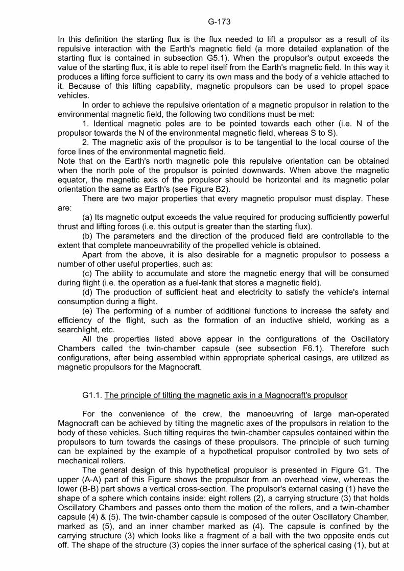
G-173
In this definition the starting flux is the flux needed to lift a propulsor as a result of its repulsive interaction with the Earth's magnetic field (a more detailed explanation of the starting flux is contained in subsection G5.1). When the propulsor's output exceeds the value of the starting flux, it is able to repel itself from the Earth's magnetic field. In this way it produces a lifting force sufficient to carry its own mass and the body of a vehicle attached to it. Because of this lifting capability, magnetic propulsors can be used to propel space vehicles. In order to achieve the repulsive orientation of a magnetic propulsor in relation to the environmental magnetic field, the following two conditions must be met: 1. Identical magnetic poles are to be pointed towards each other (i.e. N of the propulsor towards the N of the environmental magnetic field, whereas S to S). 2. The magnetic axis of the propulsor is to be tangential to the local course of the force lines of the environmental magnetic field. Note that on the Earth's north magnetic pole this repulsive orientation can be obtained when the north pole of the propulsor is pointed downwards. When above the magnetic equator, the magnetic axis of the propulsor should be horizontal and its magnetic polar orientation the same as Earth's (see Figure B2). There are two major properties that every magnetic propulsor must display. These are: (a) Its magnetic output exceeds the value required for producing sufficiently powerful thrust and lifting forces (i.e. this output is greater than the starting flux). (b) The parameters and the direction of the produced field are controllable to the extent that complete manoeuvrability of the propelled vehicle is obtained. Apart from the above, it is also desirable for a magnetic propulsor to possess a number of other useful properties, such as: (c) The ability to accumulate and store the magnetic energy that will be consumed during flight (i.e. the operation as a fuel-tank that stores a magnetic field). (d) The production of sufficient heat and electricity to satisfy the vehicle's internal consumption during a flight. (e) The performing of a number of additional functions to increase the safety and efficiency of the flight, such as the formation of an inductive shield, working as a searchlight, etc. All the properties listed above appear in the configurations of the Oscillatory Chambers called the twin-chamber capsule (see subsection F6.1). Therefore such configurations, after being assembled within appropriate spherical casings, are utilized as magnetic propulsors for the Magnocraft. G1.1. The principle of tilting the magnetic axis in a Magnocraft's propulsor For the convenience of the crew, the manoeuvring of large man-operated Magnocraft can be achieved by tilting the magnetic axes of the propulsors in relation to the body of these vehicles. Such tilting requires the twin-chamber capsules contained within the propulsors to turn towards the casings of these propulsors. The principle of such turning can be explained by the example of a hypothetical propulsor controlled by two sets of mechanical rollers. The general design of this hypothetical propulsor is presented in Figure G1. The upper (A-A) part of this Figure shows the propulsor from an overhead view, whereas the lower (B-B) part shows a vertical cross-section. The propulsor's external casing (1) have the shape of a sphere which contains inside: eight rollers (2), a carrying structure (3) that holds Oscillatory Chambers and passes onto them the motion of the rollers, and a twin-chamber capsule (4) & (5). The twin-chamber capsule is composed of the outer Oscillatory Chamber, marked as (5), and an inner chamber marked as (4). The capsule is confined by the carrying structure (3) which looks like a fragment of a ball with the two opposite ends cut off. The shape of the structure (3) copies the inner surface of the spherical casing (1), but at
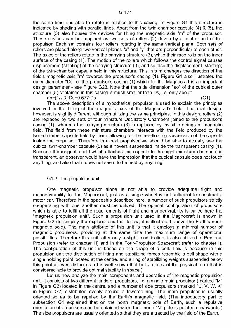
G-174
the same time it is able to rotate in relation to this casing. In Figure G1 this structure is indicated by shading with parallel lines. Apart from the twin-chamber capsule (4) & (5), the structure (3) also houses the devices for tilting the magnetic axis "m" of the propulsor. These devices can be imagined as two sets of rollers (2) driven by a control unit of the propulsor. Each set contains four rollers rotating in the same vertical plane. Both sets of rollers are placed along two vertical planes "x" and "y" that are perpendicular to each other. The axles of the rollers rotate in the carrying structure (3), while their race rolls on the inner surface of the casing (1). The motion of the rollers which follows the control signal causes displacement (slanting) of the carrying structure (3), and so also the displacement (slanting) of the twin-chamber capsule held in this structure. This in turn changes the direction of the field's magnetic axis "m" towards the propulsor's casing (1). Figure G1 also illustrates the outer diameter "Ds" of the propulsor's casing (1) which for the Magnocraft is an important design parameter - see Figure G23. Note that the side dimension "ao" of the cubical outer chamber (5) contained in this casing is much smaller than Ds, i.e. only about: ao=(1//3)·Ds=0.577·Ds (G1) The above description of a hypothetical propulsor is used to explain the principles involved in the tilting of the magnetic axis of the Magnocraft's field. The real design, however, is slightly different, although utilizing the same principles. In this design, rollers (2) are replaced by two sets of four miniature Oscillatory Chambers joined to the propulsor's casing (1), whereas the carrying structure (3) is replaced by invisible strings of magnetic field. The field from these miniature chambers interacts with the field produced by the twin-chamber capsule held by them, allowing for the free-floating suspension of the capsule inside the propulsor. Therefore in a real propulsor we should be able to actually see the cubical twin-chamber capsule (5) as it hovers suspended inside the transparent casing (1). Because the magnetic field which attaches this capsule to the eight miniature chambers is transparent, an observer would have the impression that the cubical capsule does not touch anything, and also that it does not seem to be held by anything. G1.2. The propulsion unit One magnetic propulsor alone is not able to provide adequate flight and manoeuvrability for the Magnocraft, just as a single wheel is not sufficient to construct a motor car. Therefore in the spaceship described here, a number of such propulsors strictly co-operating with one another must be utilized. The optimal configuration of propulsors which is able to fulfil all the requirements of flight and manoeuvrability is called here the "magnetic propulsion unit". Such a propulsion unit used in the Magnocraft is shown in Figure G2 (to simplify the explanations that follow, it is illustrated above the Earth's north magnetic pole). The main attribute of this unit is that it employs a minimal number of magnetic propulsors, providing at the same time the maximum range of operational possibilities. Therefore this unit, after only a slight modification, is also utilized in Personal Propulsion (refer to chapter H) and in the Four-Propulsor Spacecraft (refer to chapter I). The configuration of this unit is based on the shape of a bell. This is because in this propulsion unit the distribution of lifting and stabilizing forces resemble a bell-shape with a single holding point located at the centre, and a ring of stabilizing weights suspended below this point at even distances. (It is well-known that bells represent the physical form that is considered able to provide optimal stability in space.) Let us now analyze the main components and operation of the magnetic propulsion unit. It consists of two different kinds of propulsors, i.e. a single main propulsor (marked "M" in Figure G2) located in the centre, and a number of side propulsors (marked "U, V, W, X" in Figure G2) distributed evenly around a lowered ring. The main propulsor is usually oriented so as to be repelled by the Earth's magnetic field. (The introductory part to subsection G1 explained that on the north magnetic pole of Earth, such a repulsive orientation of propulsors can be obtained when their north "N" pole is pointed downwards.) The side propulsors are usually oriented so that they are attracted by the field of the Earth.
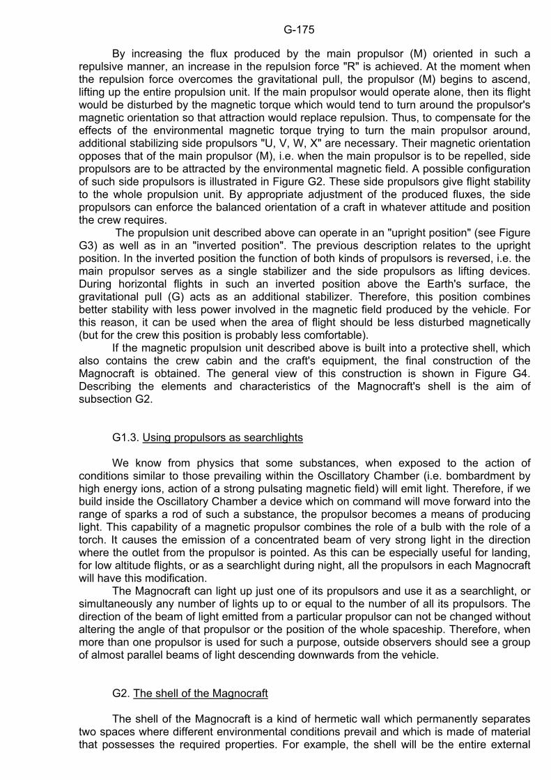
G-175
By increasing the flux produced by the main propulsor (M) oriented in such a repulsive manner, an increase in the repulsion force "R" is achieved. At the moment when the repulsion force overcomes the gravitational pull, the propulsor (M) begins to ascend, lifting up the entire propulsion unit. If the main propulsor would operate alone, then its flight would be disturbed by the magnetic torque which would tend to turn around the propulsor's magnetic orientation so that attraction would replace repulsion. Thus, to compensate for the effects of the environmental magnetic torque trying to turn the main propulsor around, additional stabilizing side propulsors "U, V, W, X" are necessary. Their magnetic orientation opposes that of the main propulsor (M), i.e. when the main propulsor is to be repelled, side propulsors are to be attracted by the environmental magnetic field. A possible configuration of such side propulsors is illustrated in Figure G2. These side propulsors give flight stability to the whole propulsion unit. By appropriate adjustment of the produced fluxes, the side propulsors can enforce the balanced orientation of a craft in whatever attitude and position the crew requires. The propulsion unit described above can operate in an "upright position" (see Figure G3) as well as in an "inverted position". The previous description relates to the upright position. In the inverted position the function of both kinds of propulsors is reversed, i.e. the main propulsor serves as a single stabilizer and the side propulsors as lifting devices. During horizontal flights in such an inverted position above the Earth's surface, the gravitational pull (G) acts as an additional stabilizer. Therefore, this position combines better stability with less power involved in the magnetic field produced by the vehicle. For this reason, it can be used when the area of flight should be less disturbed magnetically (but for the crew this position is probably less comfortable). If the magnetic propulsion unit described above is built into a protective shell, which also contains the crew cabin and the craft's equipment, the final construction of the Magnocraft is obtained. The general view of this construction is shown in Figure G4. Describing the elements and characteristics of the Magnocraft's shell is the aim of subsection G2. G1.3. Using propulsors as searchlights We know from physics that some substances, when exposed to the action of conditions similar to those prevailing within the Oscillatory Chamber (i.e. bombardment by high energy ions, action of a strong pulsating magnetic field) will emit light. Therefore, if we build inside the Oscillatory Chamber a device which on command will move forward into the range of sparks a rod of such a substance, the propulsor becomes a means of producing light. This capability of a magnetic propulsor combines the role of a bulb with the role of a torch. It causes the emission of a concentrated beam of very strong light in the direction where the outlet from the propulsor is pointed. As this can be especially useful for landing, for low altitude flights, or as a searchlight during night, all the propulsors in each Magnocraft will have this modification. The Magnocraft can light up just one of its propulsors and use it as a searchlight, or simultaneously any number of lights up to or equal to the number of all its propulsors. The direction of the beam of light emitted from a particular propulsor can not be changed without altering the angle of that propulsor or the position of the whole spaceship. Therefore, when more than one propulsor is used for such a purpose, outside observers should see a group of almost parallel beams of light descending downwards from the vehicle. G2. The shell of the Magnocraft The shell of the Magnocraft is a kind of hermetic wall which permanently separates two spaces where different environmental conditions prevail and which is made of material that possesses the required properties. For example, the shell will be the entire external
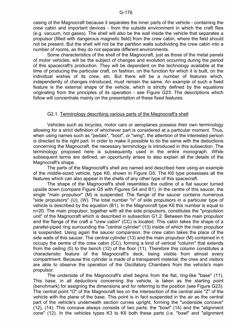
G-176
casing of the Magnocraft because it separates the inner parts of the vehicle - containing the crew cabin and important devices - from the outside environment in which the craft flies (e.g. vacuum, hot gases). The shell will also be the wall inside the vehicle that separates a propulsor (filled with dangerous magnetic field) from the crew cabin, where the field should not be present. But the shell will not be the partition walls subdividing the crew cabin into a number of rooms, as they do not separate different environments. Some characteristics of the shell of the Magnocraft, just as those of the metal panels of motor vehicles, will be the subject of changes and evolution occurring during the period of this spacecraft's production. They will be dependent on the technology available at the time of producing the particular craft, on fashion, on the function for which it is built, on the individual wishes of its crew, etc. But there will be a number of features which, independently of changes introduced, must remain the same. An example of such a fixed feature is the external shape of the vehicle, which is strictly defined by the equations originating from the principles of its operation - see Figure G23. The descriptions which follow will concentrate mainly on the presentation of these fixed features. G2.1. Terminology describing various parts of the Magnocraft's shell Vehicles such as bicycles, motor cars or aeroplanes possess their own terminology allowing for a strict definition of whichever part is considered at a particular moment. Thus, when using names such as "pedals", "boot", or "wing", the attention of the interested person is directed to the right part. In order to make it possible to do the same with the deductions concerning the Magnocraft, the necessary terminology is introduced in this subsection. The terminology proposed here is subsequently used in the entire monograph. While subsequent terms are defined, an opportunity arises to also explain all the details of the Magnocraft's shape. The parts of the Magnocraft's shell are named and described here using an example of the middle-sized vehicle, type K6, shown in Figure G5. The K6 type possesses all the features which can also appear in the shells of any other type of this spacecraft. The shape of the Magnocraft's shell resembles the outline of a flat saucer turned upside down (compare Figure G5 with Figures G4 and B1). In the centre of this saucer, the single "main propulsor" (M) is suspended. The flange of the saucer contains numerous "side propulsors" (U), (W). The total number "n" of side propulsors in a particular type of vehicle is described by the equation (B1). In the Magnocraft type K6 this number is equal to n=20. The main propulsor, together with all the side propulsors, constitutes the "propulsion unit" of the Magnocraft which is described in subsection G1.2. Between the main propulsor and the flange of the craft a "crew cabin" (CC) is located. This cabin takes the shape of a parallel-piped ring surrounding the "central cylinder" (13) inside of which the main propulsor is suspended. Using again the saucer comparison, the crew cabin takes the place of the side walls of this saucer. The central cylinder (13) and the main propulsor (M) contained in it occupy the centre of the crew cabin (CC), forming a kind of vertical "column" that extends from the ceiling (5) to the bench (12) of the floor (11). Therefore this column constitutes a characteristic feature of the Magnocraft's deck, being visible from almost every compartment. Because this cylinder is made of a transparent material, the crew and visitors are able to observe the operation of the Oscillatory Chambers from the vehicle's main propulsor. The underside of the Magnocraft's shell begins from the flat, ring-like "base" (11). This base, in all deductions concerning the vehicle, is taken as the starting point (benchmark) for assigning the dimensions and for referring to the position (see Figure G23). The central point "O" of the Magnocraft lies on the intersection of the central axis "Z" of the vehicle with the plane of the base. This point is in fact suspended in the air as the central part of the vehicle's underneath section curves upright, forming the "underside concave" (12), (14). This concave always consists of two parts: the "bowl" (14) and the "alignment cone" (12). In the vehicles types K3 to K6 both these parts (i.e. "bowl" and "alignment
G-177
cone") transform themselves tangential into each other, whereas in the rest of the Magnocraft they are joined together at almost a right angle (see Figure G24). On the upper side of the Magnocraft the "topside convex" (2), (4) appears, which in shape is exactly symmetrical to the underside concave (12), (14) described above. This topside convex also consists of two parts, the central "dome" (4) of which has the shape of a hemispherical bowl with the radius "R", whereas the side "alignment cone" (2) is a fragment of the conical surface serving as an outer shell for the crew cabin (CC). In the vehicles K3 to K6 the apical angle of the alignment cone is so selected that this cone intersects the base plane exactly under the axes of the side propulsors. Because of the symmetry of the topside convex to the underside concave, a number of Magnocraft can be stacked one on top of another in a way similar to saucers in a kitchen cupboard, thus forming a flying complex called a "stacked cigar" - see Figure G8. The distance between the topside convex and the underside concave is determined by the diameter "DM" of the main propulsor (M). The outer part of the craft's flat base (11) transforms itself into the base (10) of the "flange" (L). The flange (L) houses the side propulsors (U), ... (W). This flange has an overall appearance similar to that of the rim of a lens. The thickness of the flange is determined by the diameters "Ds" of the side propulsors which are housed inside it. Also its width is determined by the appropriate equation (G8). The top half of the flange has a magnetic "pole separator" (9) in the shape of a horizontal ring. The function of this separator is to divide the N and S magnetic poles in each of the side propulsors so that the side magnetic circuits must loop through the environment, not through the inside of the craft. The flange also houses a number of vertical partitions (not illustrated in Figure G5 but shown in Figures G4 and B1) which divide it into several magnetically separated chambers. Each chamber contains only one side propulsor. These partitions not only prevent the connection of the magnetic circuits within the craft's shell, but also prevent the circulation of plasma around the annual space holding the side propulsors. Towards the centre of the outlets from the side propulsors the upper side of the Magnocraft's flange is transformed into a "complementary flange" (6). The thickness of this flange is "Gs" (compare Figures G23 and G8). Therefore it expands onto all the unused space between the Magnocraft which are coupled into "flying systems" (see Figures G16 and G22). This allows for an additional living space when vehicles are joined into these arrangements. Further towards the centre, the complementary flange (6) joins the topside convex (2) described earlier. The border (7) between the flange and the complementary flange also forms the outer edge of the crew cabin (CC). G2.2. The Magnocraft's compartments In the shell just described, two kinds of compartments can be distinguished: the crew's living compartment (CC) and the propulsion compartments (C) and (L). The crew's living compartment extends around 360 within the cone-shaped body of the craft; it surrounds the dome-shaped free space which exists under the main propulsor (M) and column (3) in which (M) is suspended. This space is left free so as to avoid interference with the magnetic field of the main propulsor, while the direction of this field changes for the purpose of manoeuvring. In the living compartment, the crew cabin, log computer, flight engineering equipment, life support system, etc. are stored. In the types of Magnocraft larger than K4, this compartment is further subdivided into a number of smaller cabins performing specialized functions. There are also two propulsion compartments in the Magnocraft: the central compartment (C) which contains the main propulsor (M), and the lateral compartment (L) which houses the side propulsors (U), ..., (W). Both of these compartments are divided into two parts which contain the field from only one (North or South) magnetic pole of the propulsors. The central compartment (C), is divided into two sections (CN) and (Cs) by the crew cabin of which the top part is joined to the spherical casing of the main propulsor. This top part (13) separates both of the magnetic poles of the
G-178
propulsor so that the force lines of the magnetic field have to loop through the medium surrounding the craft. For the lateral compartment (L), the magnetic poles of the side propulsors are separated by a ring (9). This compartment also contains two sections (LN) and (Ls) in which only a field from one pole prevails. G2.3. The Magnocraft's facilities Two other important features of the Magnocraft are its telescopic legs and its periscopes. The legs (15) lie along the conical section of the interior wall (12) of the crew cabin, extending from the ceiling (5). In flight, when the legs are fully retracted, they do not protrude below the base (11) but are extended at the moment of landing. The angled position of the legs gives them numerous advantages which are of an important consideration when landing on uneven ground. The number of legs may differ according to the type of craft. But they must always occupy positions between the side propulsors, thereby avoiding interference with the magnetic field yield from them. Smaller Magnocraft, whose number of side propulsors "n" is a multiple of three (e.g. K4, K7 types) have three telescopic legs, whilst all others have four - see Table G1. Larger Magnocraft have a multiple of three (in K10 type) or a multiple of four (in K8 and K9 types) legs. Magnocraft are also equipped with four side periscopes (1) extending from the ceiling of the crew cabin, and two base periscopes (not shown in Figure G5). These are capable of extending beyond the range of the "ionic whirl" (see Figure G32) generated by the Magnocraft when it is operating in the magnetic whirl mode, and thus assist the crew in making precise manoeuvres. When the vehicle is in this mode of operation, the periscopes provide the only outside visual contact. To shield these periscopes from the destructive action of a plasma saw, their surface is protected by miniature magnetic screens. G2.4. Materials for the Magnocraft's shell Two drastically different types of material should be used to create the shell of the Magnocraft. The first, which hermetically covers the living compartment and also forms the separatory ring (9) with its vertical partitions, must possess magnetoreflective (magnetoresistive) properties. So the dimensionless parameter of its diamagnetic susceptibility must be x=-1. On the other hand, the second material, which covers aerodynamically the outside surfaces of the propulsion compartments, must provide maximum magnetic conductivity. Its diamagnetic susceptibility therefore must be x=0. This is vital, as any significant resistance to the magnetic flux could result in destructive energy conversion. Independently of these main magnetic properties, both materials must also be: 1. Electrical non-conductors. 2. Transparent/mirror-like (with a regulated ratio of transparency to light reflection). This means that materials should be able to either act like transparent glass or like a mirror (i.e. in extreme they should either let all light pass through them, or reflect all the light). Moreover, materials should also allow for a smooth control into any state between these two extremes (i.e. into any state between complete transparency - like glass, and complete light reflection - like a mirror). 3. Of robust mechanical construction. 4. Resistant to conversion of magnetic energy into any other form of energy (e.g. heat). It should not be very difficult to produce a magneto-conductive material which fulfils the above requirements. We already know some substances (e.g. various kinds of glass) which are probably suitable. The real problem seems to lie in obtaining an appropriate magnetoreflective material. Although in nature a substance is known which displays a high magnetoreflectiveness, i.e. graphite; unfortunately it is also a good electric conductor. A non-conductive version of graphite, called "vitreous carbon", which is also highly
G-179
magnetoreflective, provides better prospects for this application, however it still is non-transparent. Thus the Magnocraft covered by it would not provide any visibility to its crew. Therefore, it seems that the production of the Magnocraft's shell will require a material specially engineered for this purpose. The guidelines for engineering such a material are provided by the so-called "electrodynamic model of magnetoreflectiveness". G2.4.1. The electrodynamic model of magnetoreflectiveness By "magnetoreflectiveness" we understand a property of materials, which allows them to reflect magnetic fields in a way similar to the way mirrors reflect light. It is necessary for some parts of the Magnocraft's shell (especially those encasing the crew cabin) to be perfectly magnetoreflective, i.e. they must reflect the entire 100% of the magnetic flux that is striking upon them. In the research to date on magnetoreflectiveness, only the natural abilities of some chemical structures were utilized. Theoretically, however, there is another way of achieving the same effect. This way employs the Contradictory Rule governing electro-magnetism. According to this rule, every change of a magnetic field within a conductive material induces an electric current which produces its own magnetic field that is contradictory to the field inducing it. It is the Contradictory Rule which makes electric superconductors also perfect magnetic screens. But this rule can not be utilized directly by producing an electrically conductive shell for the Magnocraft. Large plates of such a shell would allow to induce within them extremely powerful electric currents that would produce an enormous amount of heat. In turn, this heat would be able to evaporate the vehicle. There is, however, another way of achieving the same effect. The heat problem can be solved if the size of the conductive circuits is decreased to an atomic scale. To achieve this, microscopic droplets, about 5 m in diameter, of electrically polarized conductive material should be spread uniformly within the volume of an electric insulator. Each such droplet would contain only a few (i.e. up to about a hundred maximum) atoms. The spreading of these droplets would be similar to the distribution of graphite spheroids within modified cast-iron. In such small polarized conductive droplets, insulated electrically from each other, electric currents would take the form of a synchronization of movement of electrons within atomic orbits. Therefore, these currents would not be able to yield any heat, while still obeying the Contradictory Rule. In this way the currents would be able to produce the internal magnetic fields that would neutralize the action of an external field that induces them, while the vehicle's shell would remain cool. The above theoretical principle, on which this dynamic manner of forming magnetoreflectiveness is based, is called the "electrodynamic model of magnetoreflectiveness". Of course, the technological implementation of the above model is not an easy task. This is because the obtaining of such material would encounter problems at two different levels, i.e. its design and its production. The main problems relating to the material's design are: selecting the chemical elements most appropriate for the conductive droplets and for the insulative material that will host them, and finding the optimal size of droplets and their optimal density in insulative material. The main problems with the production of such magnetoreflective material are caused by the necessity for the forced polarization of all atoms in the droplets (i.e. orienting all atoms within each droplet in the same direction), and on keeping the size and spatial distribution of droplets at the required level. It should be stressed that the need for forced polarization of atoms inside each droplet imposes the use of a powerful electric field during the formation of such magnetoreflective material. In turn such polarized material must display some rather unique physical properties, for example when cut with a saw or file it must produce streams of powerful sparks (like the flint from a cigarette lighter). G3. Shapes of the coupled Magnocraft
G-180
One of the most important attributes of the Magnocraft's propulsors is that they allow for easy and complete control over the produced output and over the orientation of their magnetic poles. Therefore, independently of their propelling functions, these propulsors can also be used as coupling devices, allowing for an attachment of one vehicle to another without disturbing the flight possibilities of either of them. The forces that join together the coupled Magnocraft are provided by the magnetic interaction of the vehicles' propulsors brought close to one another. Such an easy manner of joining several Magnocraft into a flying arrangement, combined with the numerous advantages that it provides, ensure that the coupling of these vehicles is a very common practice. Therefore observers of these spacecraft may on one occasion witness them as a single vehicle of an inverted saucer shape, whereas on another occasion they may see them as spheres, cigars, platforms, crosses, or hundreds of other possible shapes that can be arranged from several Magnocraft coupled together. The main advantage of coupling Magnocraft together is the ability to pilot the whole resultant arrangement by a single crew on duty, while other crews can rest, investigate, consult each other, or socialize. Additional advantages include: setting up an inductive shield of greater width that makes travel much safer; an increase in propulsive power which subsequently enables the attainment of speeds higher and more uniform in heavier mediums than those of solo flights; an increase in the total number of compartments and the range of crew specializations. During long-distance interstellar voyages, the coupling increases security and comfort of flight, allows for the socializing of crews from different vehicles, and also makes it possible to transport damaged Magnocraft. G3.1. The six classes of the Magnocraft arrangements There are three factors which determine the shape and properties of the flying arrangements obtained as a result of coupling several Magnocraft together: (a) The type of propulsors that face or interact with each other in each pair of joined vehicles. We can distinguish here as many as three different combinations: (1) main to main, (2) main to side, and (3) side to side. (b) The character of the magnetic interaction occurring between each pair of facing propulsors, i.e. if it is (1) attraction, or (2) repulsion. (c) The type of contact occurring between the shells of both joined craft. This contact can be one of the following: (1) fixed (e.g. plane to plane or cone to cone), (2) labile (e.g. two spheres touching each other in a point), and (3) detached (i.e. there is no physical contact between these shells). The way the above three factors are combined together categorizes a particular flying arrangement into a specific class. There can be distinguished as many as six basic classes of different arrangements obtained through various manners of coupling the Magnocraft. Examples of these are illustrated in Figure G6. These classes are as follows: #1. Flying complexes - see Figures G7 to G10. These are obtained when in the joined craft: (a) main propulsors always face other main propulsors and side propulsors always face other side propulsors; (b) all propulsors (i.e. main and side) create only attractive interactions; and (c) the coupling provides only fixed contacts. #2. Semi-attached configurations - see Figures G11 and G12. In these arrangements: (a) the facing of the propulsors is the same as in the flying complexes; (b) the attractive interactions are formed only by the main propulsors, whereas the side propulsors of both vehicles repel one another; and (c) the contact between the vehicles is only labile (i.e. occurring only at the point where two convex hemispheres touch each other). In spite of such labile contact, the configuration is permanent and steady because the combining of the attractive and repulsive interactions between vehicles joined together provides the required stability. #3. Detached configurations - see Figure G13. In these: (a) propulsors are faced in the same manner as in the physical complexes and semi-attached configurations; (b) the
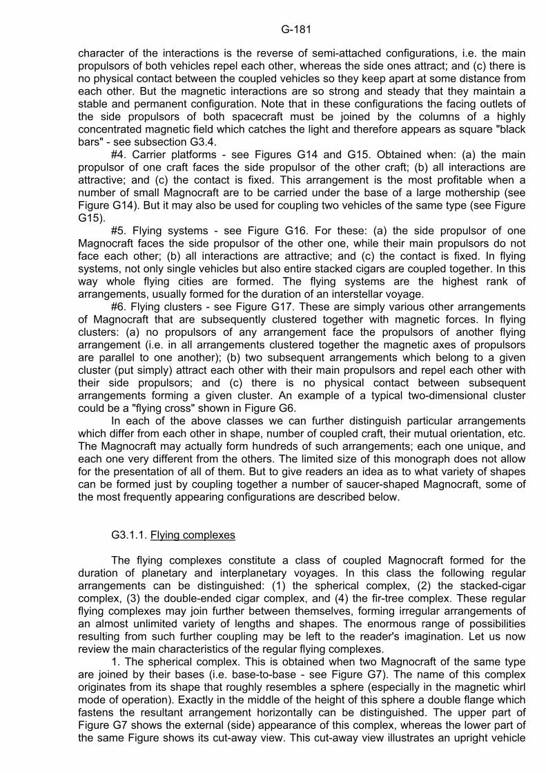
G-181
character of the interactions is the reverse of semi-attached configurations, i.e. the main propulsors of both vehicles repel each other, whereas the side ones attract; and (c) there is no physical contact between the coupled vehicles so they keep apart at some distance from each other. But the magnetic interactions are so strong and steady that they maintain a stable and permanent configuration. Note that in these configurations the facing outlets of the side propulsors of both spacecraft must be joined by the columns of a highly concentrated magnetic field which catches the light and therefore appears as square "black bars" - see subsection G3.4. #4. Carrier platforms - see Figures G14 and G15. Obtained when: (a) the main propulsor of one craft faces the side propulsor of the other craft; (b) all interactions are attractive; and (c) the contact is fixed. This arrangement is the most profitable when a number of small Magnocraft are to be carried under the base of a large mothership (see Figure G14). But it may also be used for coupling two vehicles of the same type (see Figure G15). #5. Flying systems - see Figure G16. For these: (a) the side propulsor of one Magnocraft faces the side propulsor of the other one, while their main propulsors do not face each other; (b) all interactions are attractive; and (c) the contact is fixed. In flying systems, not only single vehicles but also entire stacked cigars are coupled together. In this way whole flying cities are formed. The flying systems are the highest rank of arrangements, usually formed for the duration of an interstellar voyage. #6. Flying clusters - see Figure G17. These are simply various other arrangements of Magnocraft that are subsequently clustered together with magnetic forces. In flying clusters: (a) no propulsors of any arrangement face the propulsors of another flying arrangement (i.e. in all arrangements clustered together the magnetic axes of propulsors are parallel to one another); (b) two subsequent arrangements which belong to a given cluster (put simply) attract each other with their main propulsors and repel each other with their side propulsors; and (c) there is no physical contact between subsequent arrangements forming a given cluster. An example of a typical two-dimensional cluster could be a "flying cross" shown in Figure G6. In each of the above classes we can further distinguish particular arrangements which differ from each other in shape, number of coupled craft, their mutual orientation, etc. The Magnocraft may actually form hundreds of such arrangements; each one unique, and each one very different from the others. The limited size of this monograph does not allow for the presentation of all of them. But to give readers an idea as to what variety of shapes can be formed just by coupling together a number of saucer-shaped Magnocraft, some of the most frequently appearing configurations are described below. G3.1.1. Flying complexes The flying complexes constitute a class of coupled Magnocraft formed for the duration of planetary and interplanetary voyages. In this class the following regular arrangements can be distinguished: (1) the spherical complex, (2) the stacked-cigar complex, (3) the double-ended cigar complex, and (4) the fir-tree complex. These regular flying complexes may join further between themselves, forming irregular arrangements of an almost unlimited variety of lengths and shapes. The enormous range of possibilities resulting from such further coupling may be left to the reader's imagination. Let us now review the main characteristics of the regular flying complexes. 1. The spherical complex. This is obtained when two Magnocraft of the same type are joined by their bases (i.e. base-to-base - see Figure G7). The name of this complex originates from its shape that roughly resembles a sphere (especially in the magnetic whirl mode of operation). Exactly in the middle of the height of this sphere a double flange which fastens the resultant arrangement horizontally can be distinguished. The upper part of Figure G7 shows the external (side) appearance of this complex, whereas the lower part of the same Figure shows its cut-away view. This cut-away view illustrates an upright vehicle
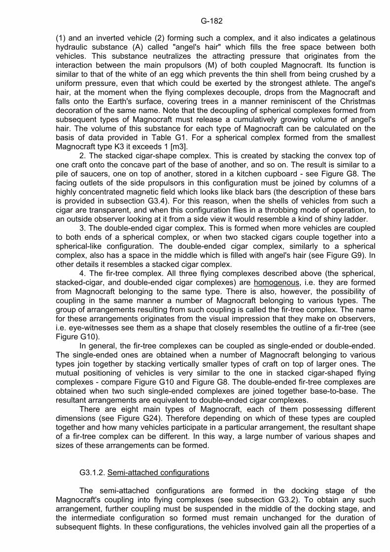
G-182
(1) and an inverted vehicle (2) forming such a complex, and it also indicates a gelatinous hydraulic substance (A) called "angel's hair" which fills the free space between both vehicles. This substance neutralizes the attracting pressure that originates from the interaction between the main propulsors (M) of both coupled Magnocraft. Its function is similar to that of the white of an egg which prevents the thin shell from being crushed by a uniform pressure, even that which could be exerted by the strongest athlete. The angel's hair, at the moment when the flying complexes decouple, drops from the Magnocraft and falls onto the Earth's surface, covering trees in a manner reminiscent of the Christmas decoration of the same name. Note that the decoupling of spherical complexes formed from subsequent types of Magnocraft must release a cumulatively growing volume of angel's hair. The volume of this substance for each type of Magnocraft can be calculated on the basis of data provided in Table G1. For a spherical complex formed from the smallest Magnocraft type K3 it exceeds 1 [m3]. 2. The stacked cigar-shape complex. This is created by stacking the convex top of one craft onto the concave part of the base of another, and so on. The result is similar to a pile of saucers, one on top of another, stored in a kitchen cupboard - see Figure G8. The facing outlets of the side propulsors in this configuration must be joined by columns of a highly concentrated magnetic field which looks like black bars (the description of these bars is provided in subsection G3.4). For this reason, when the shells of vehicles from such a cigar are transparent, and when this configuration flies in a throbbing mode of operation, to an outside observer looking at it from a side view it would resemble a kind of shiny ladder. 3. The double-ended cigar complex. This is formed when more vehicles are coupled to both ends of a spherical complex, or when two stacked cigars couple together into a spherical-like configuration. The double-ended cigar complex, similarly to a spherical complex, also has a space in the middle which is filled with angel's hair (see Figure G9). In other details it resembles a stacked cigar complex. 4. The fir-tree complex. All three flying complexes described above (the spherical, stacked-cigar, and double-ended cigar complexes) are homogenous, i.e. they are formed from Magnocraft belonging to the same type. There is also, however, the possibility of coupling in the same manner a number of Magnocraft belonging to various types. The group of arrangements resulting from such coupling is called the fir-tree complex. The name for these arrangements originates from the visual impression that they make on observers, i.e. eye-witnesses see them as a shape that closely resembles the outline of a fir-tree (see Figure G10). In general, the fir-tree complexes can be coupled as single-ended or double-ended. The single-ended ones are obtained when a number of Magnocraft belonging to various types join together by stacking vertically smaller types of craft on top of larger ones. The mutual positioning of vehicles is very similar to the one in stacked cigar-shaped flying complexes - compare Figure G10 and Figure G8. The double-ended fir-tree complexes are obtained when two such single-ended complexes are joined together base-to-base. The resultant arrangements are equivalent to double-ended cigar complexes. There are eight main types of Magnocraft, each of them possessing different dimensions (see Figure G24). Therefore depending on which of these types are coupled together and how many vehicles participate in a particular arrangement, the resultant shape of a fir-tree complex can be different. In this way, a large number of various shapes and sizes of these arrangements can be formed. G3.1.2. Semi-attached configurations The semi-attached configurations are formed in the docking stage of the Magnocraft's coupling into flying complexes (see subsection G3.2). To obtain any such arrangement, further coupling must be suspended in the middle of the docking stage, and the intermediate configuration so formed must remain unchanged for the duration of subsequent flights. In these configurations, the vehicles involved gain all the properties of a
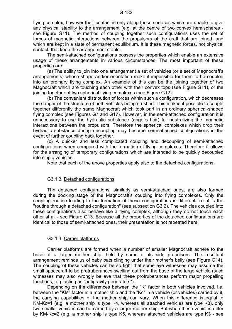
G-183
flying complex, however their contact is only along those surfaces which are unable to give any physical stability to the arrangement (e.g. at the centre of two convex hemispheres - see Figure G11). The method of coupling together such configurations uses the set of forces of magnetic interactions between the propulsors of the craft that are joined, and which are kept in a state of permanent equilibrium. It is these magnetic forces, not physical contact, that keep the arrangement stable. The semi-attached configurations possess the properties which enable an extensive usage of these arrangements in various circumstances. The most important of these properties are: (a) The ability to join into one arrangement a set of vehicles (or a set of Magnocraft's arrangements) whose shape and/or orientation make it impossible for them to be coupled into an ordinary flying complex. An example of this can be the joining together of two Magnocraft which are touching each other with their convex tops (see Figure G11), or the joining together of two spherical flying complexes (see Figure G12). (b) The convenient distribution of forces within such a configuration, which decreases the danger of the structure of both vehicles being crushed. This makes it possible to couple together differently the same Magnocraft which took part in an ordinary spherical-shaped flying complex (see Figures G7 and G17). However, in the semi-attached configuration it is unnecessary to use the hydraulic substance (angel's hair) for neutralizing the magnetic interactions between the propulsors. Therefore the spherical complexes which drop their hydraulic substance during decoupling may become semi-attached configurations in the event of further coupling back together. (c) A quicker and less complicated coupling and decoupling of semi-attached configurations when compared with the formation of flying complexes. Therefore it allows for the arranging of temporary configurations which are intended to be quickly decoupled into single vehicles. Note that each of the above properties apply also to the detached configurations. G3.1.3. Detached configurations The detached configurations, similarly as semi-attached ones, are also formed during the docking stage of the Magnocraft's coupling into flying complexes. Only the coupling routine leading to the formation of these configurations is different, i.e. it is the "routine through a detached configuration" (see subsection G3.2). The vehicles coupled into these configurations also behave like a flying complex, although they do not touch each other at all - see Figure G13. Because all the properties of the detached configurations are identical to those of semi-attached ones, their presentation is not repeated here. G3.1.4. Carrier platforms Carrier platforms are formed when a number of smaller Magnocraft adhere to the base of a larger mother ship, held by some of its side propulsors. The resultant arrangement reminds us of baby bats clinging under their mother's belly (see Figure G14). The coupling of these vehicles can be so tight that some eye witnesses may assume the small spacecraft to be protruberances swelling out from the base of the large vehicle (such witnesses may also wrongly believe that these protruberances perform major propelling functions, e.g. acting as "antigravity generators"). Depending on the differences between the "K" factor in both vehicles involved, i.e. between the "KM" factor in a mother ship and the "Kc" in a vehicle (or vehicles) carried by it, the carrying capabilities of the mother ship can vary. When this difference is equal to KM-Kc=1 (e.g. a mother ship is type K4, whereas all attached vehicles are type K3), only two smaller vehicles can be carried by a larger mother ship. But when these vehicles differ by KM-Kc=2 (e.g. a mother ship is type K5, whereas attached vehicles are type K3 - see
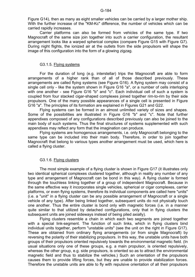
G-184
Figure G14), then as many as eight smaller vehicles can be carried by a larger mother ship. With the further increase of the "KM-Kc" difference, the number of vehicles which can be carried rapidly increases. Carrier platforms can also be formed from vehicles of the same type. If two Magnocraft of the same size join together into such a carrier configuration, the resultant arrangement looks like a warped spherical complex (compare Figure G15 with Figure G7). During night flights, the ionized air at the outlets from the side propulsors will shape the image of this configuration into the form of a glowing zigzag. G3.1.5. Flying systems For the duration of long (e.g. interstellar) trips the Magnocraft are able to form arrangements of a higher rank than of all of those described previously. These arrangements are called flying systems (see Figure G16). A flying system may consist of a single cell only - like the system shown in Figure G16 "a", or a number of cells interloping with one another - see Figure G16 "b" and "c". Each individual cell of such a system is coupled from four stacked cigar-shaped complexes joined together rim-to-rim by their side propulsors. One of the many possible appearances of a single cell is presented in Figure G16 "a". The principles of its formation are explained in Figures G21 and G22. Flying systems can be formed in an almost unlimited variety of sizes and shapes. Some of the possibilities are illustrated in Figure G16 "b" and "c". Note that further appendixes composed of any configurations described previously can also be joined to the main body of such systems. Thus the final structures of systems supplemented with such appendixes may reflect any form that the imagination can produce. Flying systems are homogenous arrangements, i.e. only Magnocraft belonging to the same type can be included into their main body. Therefore, in order to join together Magnocraft that belong to various types another arrangement must be used, which here is called a flying cluster. G3.1.6. Flying clusters The most simple example of a flying cluster is shown in Figure G17 (it illustrates only two identical spherical complexes clustered together, although in reality any number of any type and arrangement of Magnocraft can be bond in this way). A flying cluster is formed through the touchless linking together of a group of independent Magnocraft. Because in the same effective way it incorporates single vehicles, spherical or cigar complexes, carrier platforms, or even flying systems, therefore its individual components are called here "units" (i.e. a "unit" in a flying cluster can be any possible arrangement of Magnocraft or a single vehicle of any type). After being linked together, subsequent units do not physically touch one another. Thus the entire cluster is bond only with magnetic forces (i.e. in a manner quite similar to that utilized by detached configurations, only that in flying clusters the subsequent units are joined sideways instead of being piled axially). Flying clusters resemble a chain in which each two segments are joined together with a special link-segment. The function of such links, which in flying clusters bind individual units together, perform "unstable units" (see the unit on the right in Figure G17). These are obtained from ordinary flying arrangements (or from single Magnocraft) by reversing the polarity of their stabilizing propulsors. In this way, the unstable units have both groups of their propulsors oriented repulsively towards the environmental magnetic field. (In usual situations only one of these groups, e.g. a main propulsor, is oriented repulsively, whereas the other group, e.g. side propulsors, is oriented so as to attract the environmental magnetic field and thus to stabilize the vehicles.) Such an orientation of the propulsors causes them to provide lifting forces, but they are unable to provide stabilization forces. Therefore the unstable units are able to fly with repulsive orientation of all their propulsors
G-185
only when they are attached to some stable units (see the left unit in Figure G17). Such an attachment causes the stable units to ensure the stability of the unstable units. Because of the linking function that unstable units perform, every second unit of a cluster must have such reversed polarity of its propulsors to become an unstable unit. The magnetic circuits are utilized in flying clusters for two different purposes. Apart from their usual lifting and stabilizing functions, they additionally serve the purpose of coupling. Using this purpose as a criterion, as many as four separate categories of magnetic circuits can be distinguished - see Figure G17. These are: separating, holding, tuning, and compensating circuits. (Note that in order to not obstruct the clarity of the drawing, Figure G17 shows only single examples of each category of the circuits listed above. But in real clusters each of these circuits can appear a number of times.) The deductions below explain the purpose for each of these categories. - The separating circuits in a cluster are those that repel subsequent units from one another, thus making impossible the touching and accidental crushing of vehicles (see circuits indicated with a broken line in Figure G17). To this category belong magnetic circuits formed by almost all the side propulsors of the units participating in a given cluster. Because the orientation of the magnetic poles in all of these side propulsors is identical, they mutually repel one another, causing the separation of subsequent units. - The holding circuits are those that attract subsequent units to one another, thus allowing for their bonding (holding) together. These are formed from the outputs of the main propulsors in stable units, circulated (looped) through the main and side propulsors in unstable units see circuits (4), (5) and (6) in Figure G17. - The tuning circuits are those which allow for the final adjustments of mutual interactions between each pair of clustered units. These are formed by those pairs of side propulsors from each arrangement which are located next to the facing (2) side propulsors see circuit number (3) in Figures G17 and M13. - The compensating circuits are those that neutralize the reaction torque created by the spin of the other magnetic circuits in a given unit. In Figure G17 they are marked as (Ts). Although subsection G6.4 provides a detailed description of the function of these compensating circuits, at this stage it should be explained that they act in the same way as the tail propeller in a helicopter (i.e. they do not allow the vehicles to revolve in an opposite direction from the direction in which their magnetic whirls rotate). It is worth explaining here that when a cluster descends close to the ground, each category of its magnetic circuits scorches in the soil its own characteristic mark. A combination of these marks form the landing site of a very distinctive shape illustrated in Figure G17 "b". The clarity of this site especially increases when the cluster operates in the magnetic whirl mode. Then its whirling magnetic circuits act like powerful spinning combs, whose countless force lines sweep every inch of the soil thoroughly. Each of these circuits brushes the soil in rings, laying down every single blade of grass along perfectly circular paths. Because each different category of magnetic circuits also has a different length, depending on the height at which a given cluster hovers, only selected circuits can reach the ground and impress their own pattern on it. For this reason, various landings of such clusters in reality introduce further modifications to the basic pattern illustrated in Figure G17 "b". There are significant forces of repulsion between all the individual arrangements (or individual vehicles) forming a given cluster. Therefore they tend to stretch along straight lines. For this reason, flying clusters can be divided into linear ones and two-dimensional ones. In linear clusters, each unstable unit holds only one or two stable units which are attached to it from opposite sides. Thus, such clusters spread their individual units along a single straight line, forming a kind of "flying chain". A simple example of such a chain is shown in Figure G17. In two-dimensional clusters, unstable units may have more than two other arrangements attached symmetrically to their sides. Thus, the two-dimensional clusters create a kind of mesh or net spreading along mutually crossing lines. A typical example of a two-dimensional cluster is a "flying cross" shown in Figure G6.
G-186
Apart from the advantages of all previous arrangements (e.g. being flown by only one pilot), the flying clusters display further important advantages. Some of these are: (1) clusters allow for a simple linking together of any number of individual arrangements or single vehicles, (2) there is no restriction concerning the type of vehicles, their number, or the kind of arrangements that can be clustered together, (3) to be clustered together, individual arrangements do not need to change their existing configuration (e.g. split into individual vehicles), and (4) individual arrangements can disconnect from the cluster at any time without the need to change their configuration. G3.2. The principles of coupling and decoupling Coupling of the Magnocraft is an activity of joining these vehicles in any flying arrangement described previously. This activity is usually carried out during the vehicles' flight. The reversal of coupling, i.e. splitting flying arrangements into individual vehicles, is called decoupling in this monograph. The principles of coupling and decoupling will be explained in the example of forming a spherical flying complex. Of course exactly the same principle is also applied for coupling Magnocraft into any other arrangement. In turn, knowing this procedure of coupling, it is obvious that to decouple any arrangement into single units, the procedure described below needs only to be reversed. The entire coupling procedure is completed by only one active vehicle (in Figure G18 it is the lower one) which undergoes all transformations. The other unit (in Figure G18 the upper one) remains passive all the time, and its only function is to allow the active Magnocraft to approach it and to complete the necessary transformations. The polarity of propulsors in the active and passive units must be opposite. For example, if the propulsors of an active unit have the polarity characteristic for the inverted position (see Figure G3), then the passive unit must have the polarity characteristic for the upright position. Note that both units (i.e. passive and active) can be either single vehicles or entire flying arrangements. The coupling of two Magnocraft is conducted in three phases, called the (#1) orientation phase, (#2) the docking phase, and (#3) the linking phase (see Figure G18). Each of these phases is discussed below. #1. The "orientation phase" initiates the coupling of the active unit to a passive one. In this phase the active vehicle positions itself exactly opposite the surface to which it is later going to cling to (e.g. in Figure G18 directly beneath the passive unit). Then the active vehicle adjusts its angular position so that the outlets of its propulsors begin to face the corresponding outlets from the passive unit. The opposite polarity of the propulsors applied in the upright position and in the inverted position have the effect that in this phase both spacecraft have the same magnetic poles confronting one another. Therefore all the propulsors of both units repel one another (see Figure G3). For example, in the upright (passive) unit the North pole of the main propulsor and the South poles of the side propulsors are directed downwards, whereas in the inverted (active) Magnocraft the North pole of the main propulsor and the South poles of the side propulsors are directed upwards. In effect both Magnocraft act against each other only with repelling forces (R). This prevents the vehicles from accidentally colliding with each other. After finishing the orientation phase the active Magnocraft may advance to further stages of the coupling procedure. #2. The second phase of coupling, called the "docking phase" (see part "b" of Figure G18) contains three steps which must be completed in a very fast sequence by the active vehicle. These are: (2A) the reorientation of the magnetic poles in the active vehicle, (2B) the balancing of the forces of interactions between both vehicles, and (2C) the closing-up of the distance between both vehicles. (2A) In the first step, the active unit reorients the magnetic poles of its side propulsors from their repulsive (R) into their attractive (A) orientation towards the same propulsors of the passive unit. As a result, two opposite kinds of forces begin to co-exist
G-187
between both Magnocraft, i.e. a repulsion force (R) appears between their main propulsors, and forces of attraction (A) are produced between their side propulsors. Depending on which of these two types of forces is greater, both craft begin to move towards each other or diverge. (2B) Immediately after the reorientation of the magnetic poles is finished, the active unit must also complete the second step of the docking phase which is the balancing step. In this step the outputs from the Magnocraft's main and side propulsors are so controlled that the forces of attraction (A) and repulsion (R) between both units reach an equilibrium. This equilibrium causes both vehicles to stop further movement towards each other (or diverge) and form a kind of "solid configuration" which we call the "detached configuration". The detached configuration displays all the properties of the physical complexes, i.e. stability, consistency, permanence, etc. Only the mutual attachment of units is achieved not by mechanical means but by a magnetic field. In this state, both craft could travel a long distance together without any need for a more "physical" coupling. If the formation of such a detached configuration is the aim of the coupling routine, then further actions are discontinued at this stage and the resulting arrangement flies away, controlled by only one pilot. (2C) If both vehicles intend to couple into a physical flying complex, after the balancing step the third step of the docking phase begins to commence. In this third step the forces of reciprocal attraction (A) and repulsion (R) between the vehicles are controlled so that both Magnocraft very slowly draw nearer to each other until they achieve physical contact (e.g. base-to-base) . #3. After physical contact the vehicles begin the third phase of coupling, called the "linking phase" (see part "c" in Figure G18). In this phase the polarity of the main propulsor in the active vehicle is reoriented so its repulsion with the main propulsor of the passive unit is replaced by reciprocal attraction (A). Both craft now physically hook onto each other, forming one solid complex. The characteristic attribute of the coupling routine described above is that the vehicles subjected to it must pass through the following three stages: (1) independent units, (2) detached configuration, and (3) flying complex. Therefore we can call this routine the "routine through a detached configuration". There is also another coupling routine, shown in Figure G19, which can be called the "routine through a semi-attached configuration". This routine, during the second (docking) phase of coupling, achieves all the force interactions and the reciprocal orientation of propulsors that are characteristic for the semi-attached configurations. It should be noted that the only difference between both routines is in the type of propulsors which should be reoriented during the docking stage. For the routine through a detached configuration the side propulsors are reoriented, whereas in the routine through a semi-attached configuration it is the main propulsor whose magnetic poles are reoriented. G3.3. The hydraulic substance filling the space between the craft (angel's hair) The hydraulic substance used to fill the space between the units in the spherical and double-ended flying complexes needs some special properties. It must have a fibrous structure, similar to egg white, together with the same kind of gelatinous consistency. It cannot be a conductor of electric current, and at the same time must be an ideal magnetic field suspector. It must not convert the magnetic field energy into any other type of energy (e.g. heat). It is hypothesized that these requirements are met by the class of materials known as the borosiloxane polymers, created by borosiloxane molecular strings. They can be made by a chemical reaction of the boron hydrides with the siloxanes. An example of such a reaction is the association of the boron hydride B2H6 with the methyl siloxane (CH3)2SiO: nB2H6 + n(CH3)2SiO --- (-B-O-Si-O-)
G-188
Theoretically, such a reaction would produce a huge amount of energy, much more than that currently obtained from rocket fuels (e.g. the association of hydrogen with oxygen). Thus, a reaction similar to this could possibly be used in the future for energy production, while the polymer received (like the waste exhaust gases emitted from motor vehicles) as a byproduct from this reaction could be recycled for filling the space between the Magnocraft. Unfortunately, because this reaction has a high activation energy, it is very difficult to carry out with our present level of technology. To accomplish it much more technical know-how is necessary. It should be noted that the organic-like compound of boron with silicon, obtained in the effect of the reaction described above, is a gelatinous substance which has an absolutely neutral effect on the environment and people. Its serially connected borosiloxane strings can have a fibrous consistency. As a result of the water (which is present in the air) attacking the boron, these strings crack, creating volatile chemical compounds of the boraxine (BHO)3 type. Therefore, the hydraulic substance which is dropped from decoupling complexes onto the Earth does not pollute the natural environment, and also evaporates after a while. Another name for this hydraulic substance is the term "angel's hair", as when it is dropped from a vehicle and lands on a tree, it covers it with strands of long, wet, glassy fibers, creating a visual impression similar to that of the well-known Christmas tree decoration of the same name. G3.4. The black bars of the magnetic field There are some arrangements of the Magnocraft, e.g. the semi-attached or detached configurations (see Figures G11 to G13) and the cigar-shaped complexes (Figures G8 & G9), in which the side propulsors belonging to different vehicles face and attract one another, at the same time being kept at a distance. Therefore the highly concentrated magnetic field yielded by these propulsors passes through the environment, forming types of dense columns with clearly distinguishable boundaries. These columns, when observed from a direction that is perpendicular to the field's force lines, must trap and absorb the light, thus appearing to eye-witnesses as black, square bars. Because they appear intensely dark, they can be taken as solid forms extending from the structure of the vehicles. The cross section of these columns reflects the square shape of the Oscillatory Chambers which produce the field forming them. In various arrangements of the Magnocraft, the number of these black bars is always be equal to the number of operational side propulsors contained in the coupled vehicles. This could facilitate the type identification of the coupled vehicles, but unfortunately every such bar can not always be seen, as some of them can be hidden behind the vehicles' shells or behind other black bars. Notice that in semi-attached configurations the black bars pass between the main and side propulsors of the facing vehicles (see Figure G11). A phenomenon identical to that which causes the black bars to appear is also in action during sightings of twin-chamber capsules - see Figure F5. The circulating flux of such capsules, when observed from a direction perpendicular to the field force lines, is perceived as an area of complete blackness. Moreover, when a Magnocraft's propulsor operating in the outer flux prevalence is observed from the inside of this vehicle, for the same reason it also looks as though it is filled with black smoke. (Further details concerning the phenomena involved in the blackish appearance of the Magnocraft's field observed from a direction perpendicular to its force lines are presented in subsection G9.4.) G4. The conditions defining the shape of the Magnocraft's shell Every type of propulsion imposes a unique set of requirements on the vehicles which utilize it. These requirements cause that a given type of vehicles must always display
G-189
certain fixed attributes, independently of who builds them, and when and where they are built. An example of such fixed attributes can be the wheels of a car, which must always be underneath it (e.g. even the most advanced cosmic intelligence is unlikely to build a car whose wheels are placed on the upper side). Other examples can include the wings of an aeroplane (it is impossible to build an aeroplane without some form of wings) and the hull of a boat (which must have an aerodynamic shape). The propulsion used in the Magnocraft also imposes a set of such unchangeable requirements. They dictate that the shell of this vehicle is strictly defined by a set of mathematical equations. The subsection that follows reviews the most basic conditions which the shell of the Magnocraft must fulfil, and presents the impact of these conditions on the final shape of this vehicle. In subsection B2.2 the primary requirement for building a controllable propulsion system was described. This requirement states that the principle of operation of the propulsion must allow the working medium to circulate through the environment. For the Magnocraft this means that its magnetic field must form closed circuits whose paths must cross the environment. To fulfil this condition, the shell of this vehicle must be shaped in such a way that: 1. Both outlets from every propulsor must open out onto the environment. 2. Both poles of the same propulsor must be separated from each other so that the magnetic field is forced to circulate around the outside of the vehicle. 3. Every propulsor must be located in a separate chamber which only opens out onto the environment so that the magnetic field is prevented from forming circuits within the craft. Above describes only one of numerous conditions that the shell of the Magnocraft must fulfil. This condition makes us realize that this vehicle is also subject to a distinct chain of causes and effects (causes are unique requirements imposed by the principles of operation of the Magnocraft, whereas effects are the ways in which the construction of the Magnocraft must be formulated so that it fulfils all these requirements). This cause-effect chain very strictly defines the shape and the mutual ratio of dimensions of the vehicle. These definitions take the form of a set of equations which the shape of the Magnocraft must fulfil. The consequence of the chain of causes and effects described above is that not many details are left to the choice of the designer of the Magnocraft. Almost every element of its shell, every dimension and shape is strictly defined by numerous conditions. Let us now, one by one, analyze each such cause and mathematically describe its effects. G4.1. The condition of equilibrium between the thrust and stabilization forces The Magnocraft's propulsion is designed for equally effective flights in both possible positions, i.e. upright and inverted - see Figure G3. There are also some situations, for example coupling and decoupling into flying arrangements (see subsection G3.2), where the function of particular propulsors must be reversed. These reasons make it necessary for the propulsion unit of the Magnocraft to be designed in such a way that the total output produced by all the side propulsors is equal to the magnetic output provided by the main propulsor. Only in such a case can a selected kind of propulsor (i.e. the main or the side) in one application be used for propelling and in the other application be used for stabilization. Because the force of magnetic interaction is proportional to the output from the propulsor, the requirement presented here is called the "condition of the equilibrium between the thrust and stabilization forces". The propulsors of the Magnocraft are built as cubical twin-chamber capsules and are located within the spherical casing (see Figure G1). The external diameters of these casings, i.e. DM and Ds, are the parameters that directly impact the shape and dimensions of the vehicle's shell - see subsection G2. But the diameters DM and Ds of the propulsors' casings must depend on the output provided by the chambers located within them. This dependence results from the requirement that in the state of magnetic equilibrium, the density of energies in the main and side propulsors must be equal. To achieve such
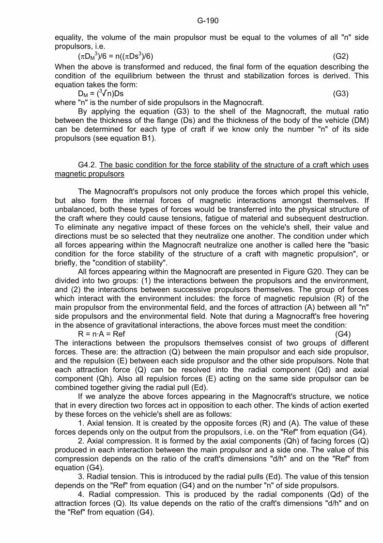
G-190
equality, the volume of the main propulsor must be equal to the volumes of all "n" side propulsors, i.e. (ΠDM
3)/6 = n((ΠDs3)/6) (G2) When the above is transformed and reduced, the final form of the equation describing the condition of the equilibrium between the thrust and stabilization forces is derived. This equation takes the form: DM = (3/n)Ds (G3) where "n" is the number of side propulsors in the Magnocraft. By applying the equation (G3) to the shell of the Magnocraft, the mutual ratio between the thickness of the flange (Ds) and the thickness of the body of the vehicle (DM) can be determined for each type of craft if we know only the number "n" of its side propulsors (see equation B1). G4.2. The basic condition for the force stability of the structure of a craft which uses magnetic propulsors The Magnocraft's propulsors not only produce the forces which propel this vehicle, but also form the internal forces of magnetic interactions amongst themselves. If unbalanced, both these types of forces would be transferred into the physical structure of the craft where they could cause tensions, fatigue of material and subsequent destruction. To eliminate any negative impact of these forces on the vehicle's shell, their value and directions must be so selected that they neutralize one another. The condition under which all forces appearing within the Magnocraft neutralize one another is called here the "basic condition for the force stability of the structure of a craft with magnetic propulsion", or briefly, the "condition of stability". All forces appearing within the Magnocraft are presented in Figure G20. They can be divided into two groups: (1) the interactions between the propulsors and the environment, and (2) the interactions between successive propulsors themselves. The group of forces which interact with the environment includes: the force of magnetic repulsion (R) of the main propulsor from the environmental field, and the forces of attraction (A) between all "n" side propulsors and the environmental field. Note that during a Magnocraft's free hovering in the absence of gravitational interactions, the above forces must meet the condition: R = n·A = Ref (G4) The interactions between the propulsors themselves consist of two groups of different forces. These are: the attraction (Q) between the main propulsor and each side propulsor, and the repulsion (E) between each side propulsor and the other side propulsors. Note that each attraction force (Q) can be resolved into the radial component (Qd) and axial component (Qh). Also all repulsion forces (E) acting on the same side propulsor can be combined together giving the radial pull (Ed). If we analyze the above forces appearing in the Magnocraft's structure, we notice that in every direction two forces act in opposition to each other. The kinds of action exerted by these forces on the vehicle's shell are as follows: 1. Axial tension. It is created by the opposite forces (R) and (A). The value of these forces depends only on the output from the propulsors, i.e. on the "Ref" from equation (G4). 2. Axial compression. It is formed by the axial components (Qh) of facing forces (Q) produced in each interaction between the main propulsor and a side one. The value of this compression depends on the ratio of the craft's dimensions "d/h" and on the "Ref" from equation (G4). 3. Radial tension. This is introduced by the radial pulls (Ed). The value of this tension depends on the "Ref" from equation (G4) and on the number "n" of side propulsors. 4. Radial compression. This is produced by the radial components (Qd) of the attraction forces (Q). Its value depends on the ratio of the craft's dimensions "d/h" and on the "Ref" from equation (G4).
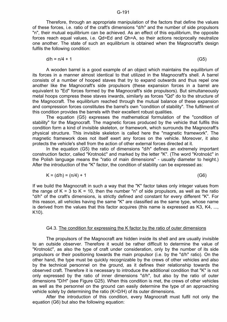
G-191
Therefore, through an appropriate manipulation of the factors that define the values of these forces, i.e. ratio of the craft's dimensions "d/h" and the number of side propulsors "n", their mutual equilibrium can be achieved. As an effect of this equilibrium, the opposite forces reach equal values, i.e. Qd=Ed and Qh=A, so their actions reciprocally neutralize one another. The state of such an equilibrium is obtained when the Magnocraft's design fulfils the following condition: d/h = n/4 + 1 (G5) A wooden barrel is a good example of an object which maintains the equilibrium of its forces in a manner almost identical to that utilized in the Magnocraft's shell. A barrel consists of a number of hooped staves that try to expand outwards and thus repel one another like the Magnocraft's side propulsors (these expansion forces in a barrel are equivalent to "Ed" forces formed by the Magnocraft's side propulsors). But simultaneously metal hoops compress these staves inwards, similarly as forces "Qd" do to the structure of the Magnocraft. The equilibrium reached through the mutual balance of these expansion and compression forces constitutes the barrel's own "condition of stability". The fulfilment of this condition provides the barrels with their excellent robust qualities. The equation (G5) expresses the mathematical formulation of the "condition of stability" for the Magnocraft. The magnetic forces produced by the vehicle that fulfils this condition form a kind of invisible skeleton, or framework, which surrounds the Magnocraft's physical structure. This invisible skeleton is called here the "magnetic framework". The magnetic framework does not itself exert any forces on the vehicle. Moreover, it also protects the vehicle's shell from the action of other external forces directed at it. In the equation (G5) the ratio of dimensions "d/h" defines an extremely important construction factor, called "Krotność" and marked by the letter "K". (The word "Krotność" in the Polish language means the "ratio of main dimensions" - usually diameter to height.) After the introduction of the "K" factor, the condition of stability can be expressed as: K = (d/h) = (n/4) + 1 (G6) If we build the Magnocraft in such a way that the "K" factor takes only integer values from the range of K = 3 to K = 10, then the number "n" of side propulsors, as well as the ratio "d/h" of the craft's dimensions, is strictly defined and constant for every different "K". For this reason, all vehicles having the same "K" are classified as the same type, whose name is derived from the values that this factor acquires (this name is expressed as K3, K4, ..., K10). G4.3. The condition for expressing the K factor by the ratio of outer dimensions The propulsors of the Magnocraft are hidden inside its shell and are usually invisible to an outside observer. Therefore it would be rather difficult to determine the value of "Krotność", as also the type of craft under consideration, only by the number of its side propulsors or their positioning towards the main propulsor (i.e. by the "d/h" ratio). On the other hand, the type must be quickly recognizable by the crews of other vehicles and also by the technical personnel on the ground, as it defines their relationship towards the observed craft. Therefore it is necessary to introduce the additional condition that "K" is not only expressed by the ratio of inner dimensions "d/h", but also by the ratio of outer dimensions "D/H" (see Figure G25). When this condition is met, the crews of other vehicles as well as the personnel on the ground can easily determine the type of an approaching vehicle solely by determining the ratio (K=D/H) of its outer dimensions. After the introduction of this condition, every Magnocraft must fulfil not only the equation (G6) but also the following equation:
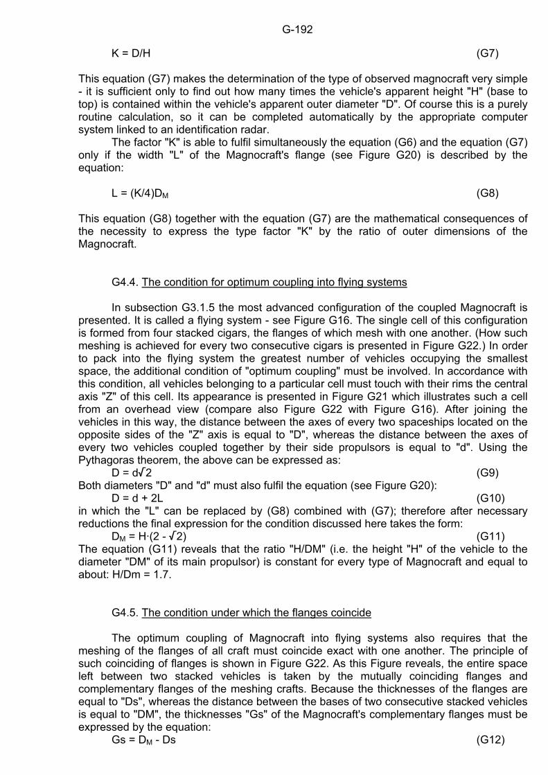
G-192
K = D/H (G7) This equation (G7) makes the determination of the type of observed magnocraft very simple - it is sufficient only to find out how many times the vehicle's apparent height "H" (base to top) is contained within the vehicle's apparent outer diameter "D". Of course this is a purely routine calculation, so it can be completed automatically by the appropriate computer system linked to an identification radar. The factor "K" is able to fulfil simultaneously the equation (G6) and the equation (G7) only if the width "L" of the Magnocraft's flange (see Figure G20) is described by the equation: L = (K/4)DM (G8) This equation (G8) together with the equation (G7) are the mathematical consequences of the necessity to express the type factor "K" by the ratio of outer dimensions of the Magnocraft. G4.4. The condition for optimum coupling into flying systems In subsection G3.1.5 the most advanced configuration of the coupled Magnocraft is presented. It is called a flying system - see Figure G16. The single cell of this configuration is formed from four stacked cigars, the flanges of which mesh with one another. (How such meshing is achieved for every two consecutive cigars is presented in Figure G22.) In order to pack into the flying system the greatest number of vehicles occupying the smallest space, the additional condition of "optimum coupling" must be involved. In accordance with this condition, all vehicles belonging to a particular cell must touch with their rims the central axis "Z" of this cell. Its appearance is presented in Figure G21 which illustrates such a cell from an overhead view (compare also Figure G22 with Figure G16). After joining the vehicles in this way, the distance between the axes of every two spaceships located on the opposite sides of the "Z" axis is equal to "D", whereas the distance between the axes of every two vehicles coupled together by their side propulsors is equal to "d". Using the Pythagoras theorem, the above can be expressed as: D = d/2 (G9) Both diameters "D" and "d" must also fulfil the equation (see Figure G20): D = d + 2L (G10) in which the "L" can be replaced by (G8) combined with (G7); therefore after necessary reductions the final expression for the condition discussed here takes the form: DM = H·(2 - /2) (G11) The equation (G11) reveals that the ratio "H/DM" (i.e. the height "H" of the vehicle to the diameter "DM" of its main propulsor) is constant for every type of Magnocraft and equal to about: H/Dm = 1.7. G4.5. The condition under which the flanges coincide The optimum coupling of Magnocraft into flying systems also requires that the meshing of the flanges of all craft must coincide exact with one another. The principle of such coinciding of flanges is shown in Figure G22. As this Figure reveals, the entire space left between two stacked vehicles is taken by the mutually coinciding flanges and complementary flanges of the meshing crafts. Because the thicknesses of the flanges are equal to "Ds", whereas the distance between the bases of two consecutive stacked vehicles is equal to "DM", the thicknesses "Gs" of the Magnocraft's complementary flanges must be expressed by the equation: Gs = DM - Ds (G12)
G-193
The fulfilment of the equations (G11) and (G12) forms the Magnocraft's shell in such a way that after these vehicles are coupled into a flying system, there is almost no space left which would not be occupied by a craft. G4.6. Types of Magnocraft By the phrase "type of Magnocraft" is understood a group of identical vehicles which share exactly the same values of: their "K" factor, design parameters (e.g. "n", dimensions), external shape, and various standardized features subjected to international (or interplanetary) agreement. Therefore any group of Magnocraft belonging to the same type is able to couple together into homogenous arrangements, independently of who produced these vehicles and when, what their purpose is, etc. All Magnocraft of the same type will also look identical from the outside and will have the same number of side propulsors. But they can be subdivided into different internal rooms, may use different materials for their shells, be produced by different countries or companies, be made in different years, and so on. It is worth mentioning here that a number of series of the Magnocraft will probably be built in the future for various purposes. We can imagine a minimum of two such series, i.e. (1) the basic series of crew-carrying vehicles, and (2) an additional series of the computer controlled Magnocraft. In these computer-controlled vehicles, types K3 to K5 could perform the functions of personal implements (e.g. weapons, couriers) whereas types K6 to K10 could perform the function of automatic probes. In each of these two series, the dimensions of particular types of vehicles must be different, but the general appearance, the number of side propulsors, and the mutual ratio of dimensions must remain the same for a given type. For the series of the crew-carrying Magnocraft, the best use of space seems to occur when outer diameters "D" of the subsequent types of vehicles fulfil the equation: D = Cc·2K [metres] (G13) in which the constant "Cc" represents the cosmic unit of length, in this monograph called the "cosmic cubit". Its value is Cc=0.5486 [metres]. The outer diameters D' of the computer controlled Magnocraft should probably be 28=256 times smaller, thus expressed by another equation of the form: D' = 2.143·2K [millimeters]. Such defining of their values would cause that the outer diameter D'K10 of the K10 type of a computer controlled Magnocraft would be equal to a half of the outer diameter DK3 of the K3 type of a crew-carrying Magnocraft, i.e.: DK3 = 2·D'K10. The above demonstrates that in fact, for the complete categorizing of the Magnocraft, there is a need to identify not only the type to which it belongs, but also the series from which this type is taken (i.e. crew or computer controlled). However, because this monograph is not concerned with the specific possibilities of the applications of the Magnocraft, in the remainder of the text any reference to a computer controlled series of the Magnocraft will not be elaborated. Therefore any further reference to a type of Magnocraft will relate solely to the crew-carrying series of this vehicle. The equation (G13) highlights the fact that the outer diameters of successive Magnocraft are organized in a binary fashion. By way of their organizing, the diameter "D" for each following type of Magnocraft is obtained by doubling the same diameter from the previous type. Because there is a linear relationship between the outer diameters "D" and all other dimensions and parameters of the Magnocraft, a number of various dimensions of these vehicles are also aligned in such a binary fashion. For example the diameters "d" of the circles of scorched vegetation left by landed Magnocraft (see Figure G38) are also organized in such a way that each subsequent circle is twice as big as the circle produced by the previous type of this vehicle. The conditions defined earlier led to the deduction of a number of equations which completely describe the geometrical shape of the shell in each type of Magnocraft. These equations are listed in Figure G23. If we use the equation (G13) for defining diameter "D" of
G-194
the subsequent vehicles, we may determine the main dimensions for the crew-carrying series of Magnocraft. These dimensions are presented in Table G1. Transforming the dimensions from Table G1 into diagrams, the outlines of all eight basic types of the Magnocraft are obtained. The final form of these outlines is presented in Figure G24. This Figure reveals that each type of Magnocraft possesses a unique and very distinct shape, which in the future will help us to visually identify them quickly and easily. G4.7. Identifying the types of Magnocraft A number of practical consequences result when the shell of the Magnocraft follows the conditions specified above. First and the most important of them, is the possibility of quick and easy identification of the type and size of the vehicles that are observed, and resulting from this, instant knowledge of almost all the construction parameters of these craft. An effective method of such quick identification of the Magnocraft's type is illustrated in Figure G25. All that is needed is to place a piece of thread, a blade of grass, a ruler, or any other linear object towards the flying Magnocraft or on a photograph of it, and then measure its apparent "H" and "D" dimensions. Next, the value of "Krotność" can immediately be established from the equation (G7) by a simple division of "D" by "H". If by this means the value of "K=D/H" is determined, almost all of the vehicle's parameters can later be found either by reading them from Table G1 or by calculating them from equations (G3) to (G13). Determining the value of the K factor for a single craft is simple; we just use equation (G7). Also when two Magnocraft are coupled together (see subsection G3.1.1) into a spherical flying complex, "K" may be calculated from the following simple equation: Kspherical = 2D/H (G14) However, the "K" determination starts to be more complicated when one of the cigar-shaped flying complexes is analyzed. In this instance the final form of the equation used depends on the value of the following ratio: H/(H - DM) = c (G15) This ratio can be determined from the equation (G11) expressing the condition of optimum coupling into flying systems. After it is determined from this condition it takes the following value: c = 1/( 2 - 1) (G16) After using this value for "c" for deducing the equation describing the "K" factor in cigar-shaped flying complexes, these equations take the following form: - for the stacked cigar-shaped complex: K = (m - (m-1)/c)(D/H) = (m - (m - 1)·(/2 - 1))(D/H) (G17) - for the double-ended cigar shaped complex: K = (m - (m-1)/c)(D/H) = (m - (m - 2)·(/2 - 1))(D/H) (G18) The "m" represents the number of Magnocraft coupled together into a given flying complex, whereas " H" is the height and "D" is the outer diameter of the resultant arrangement. Note that when the number of units takes the value m = 1, the equation (G17) reduces itself into the form of equation (G7). Similarly equation (G18), when applying the value of m = 2, transforms itself into equation (G14). The final formulas for identifying the type of Magnocraft that form one of the flying configurations considered above are listed in Table G2.
G-195
G4.8. The magnetic framework Another consequence of the "stability condition" is the resistance of the Magnocraft's structure to the action of even the highest of external pressures. Any external effects directed onto the craft are taken up by the magnetic whirl. This whirl is supported by the "magnetic framework" described in subsection G4.2. Therefore the environmental pressure is not transferred into the body of the craft, but is neutralized within the magnetic field's interactions. This makes it possible for the vehicle to withstand high pressures that otherwise would be destructive to its physical structure. Therefore the Magnocraft have the ability to penetrate the bottom of oceanic trenches where any other structure would be crushed by water pressure. Also the Magnocraft should not be in danger from any nearby explosion because the shockwaves would be stopped by the magnetic framework. The other property of the Magnocraft, called the "magnetic whirl", prevents any extremely hot medium from touching the craft's surface. Simultaneously, the strong magnetic field ("magnetic lens") bends the thermal radiation, making it impossible to illuminate the surface of the craft. Therefore, Magnocraft are able to fly through any environment consisting of melted materials. This ability, together with the magnetic framework, should allow this vehicle to penetrate the Earth's nucleus, and also perhaps the centres of stars. G5. The magnetic field of the Magnocraft The operation of the Magnocraft involves a number of issues concerning the magnetic field of this vehicle. Some of them are very important and sensitive. For example, the issue of the effective length of the Magnocraft's propulsors is overlooked by the majority of those raising critical comments that refer to the uniform character of the Earth's magnetic field. Thus, if people who put forward such comments would become familiar with the author's deductions before they formulated their objections, most of the criticism directed towards the Magnocraft to date would be avoided. For this reason, the issues mentioned need to be addressed here to give readers a complete understanding of the scientific foundations behind this vehicle. Such an understanding would also enable readers to defend this spaceship from unjustified attacks by various sceptics who do not bother to learn the details of the Magnocraft's theory, but who are nevertheless quite eager to attack it. Unfortunately, the major issues concerning the magnetic field of this vehicle are rather difficult to understand, and also their comprehension seems to require some background in science or technology. Therefore some readers may find this subsection quite difficult. To minimize the gaps when someone omits the material on the Magnocraft's magnetic field, the author has arranged this chapter so that skipping through the subsection that follows should not disadvantage their comprehension of the entire material. But for those readers who are able to work through this subsection, the author highly recommends that they do so. G5.1. The starting flux Planet Earth, apart from numerous other properties, also acts as a huge magnet. If any man-made source of a magnetic field (e.g. a propulsor) is placed in the range of its field, then magnetic interactions between the Earth and this source must occur. A visual illustration for these interactions in action is the operation of a magnetic compass. It is commonly known from physics that any two magnets can be so oriented that they repel each other. This can also be achieved with the Earth and any man-made source of magnetic field. Unfortunately in this latter case, the low density of the Earth's magnetic field and its high uniformity cause that the forces of repulsion so created are negligible. But if the
G-196
man-made device is capable of increasing its magnetic output (and thus also its effective magnetic length), the force of its repulsion from Earth must also increase. Assuming that this source has unlimited capabilities to increase its output, such a moment must inevitably occur when the force of its repulsion from Earth will exceed the gravity pull. Therefore, at this significant moment a very critical output from this device is achieved which initiates its ascent into space. This critical output is called here the "starting flux". The starting flux represents an extremely important constant for the devices that propel the Magnocraft. Its definition is as follows: "The name, starting flux (Fs), is given to such a ratio of the magnetic flux (F) to the mass (m), that any device oriented repulsively towards the field of the Earth which achieves this ratio must autogenously begin to ascend." Every man-made source of a magnetic field whose output exceeds the starting flux is able to break a gravity pull by its own force of magnetic repulsion from the Earth's field, and to ascend. Therefore the starting flux represents the magnetic equivalent of the "escape velocity" as applied in conventional space travel. Its value relates to geographical location and is lowest for the magnetic poles and highest for the magnetic equator. For the north magnetic pole of Earth it is equal to Fs=2.59 [Wb/kg]. But for the area of Poland it rises to the value of about Fs=3.45 [Wb/kg]. The starting flux is a physical constant of extreme importance for the magnetic propulsion of flying vehicles. It defines which sources of a magnetic field are only ordinary magnets and which of them can be used as magnetic propulsors. The primary condition for employing any source of a magnetic field as the magnetic propulsor is that its field-to-mass ratio must exceed the value of the starting flux. From the historic point of view the starting flux constitutes an important breakthrough separating two eras. Until the completion of the device whose output will exceed the starting flux, the era of propulsion systems operating on the principle of circulation of matter (see Table B1) prevails on Earth. After the completion of such a device, the era of the magnetic propulsion of flying vehicles will arrive on Earth. Up to now our devices for producing a controlled magnetic field (called electromagnets) possess a number of drawbacks that make it impossible to attain the outputs equal to, or greater than, the value of the starting flux. These drawbacks are listed in subsection F1. The Oscillatory Chamber described in chapter F of this monograph is the first device whose principles of operation allow us to achieve outputs higher that the value of the starting flux. G5.2. The naming of the magnetic poles In contemporary physics there is a rule for the naming of the magnetic poles which states that: "The 'North (N) magnetic pole' is understood to be the pole of the magnetic needle tip pointing northward". As a result of this notation, the North geographic pole is actually adjacent to the South magnetic pole and vice versa. Perhaps the above complication does not matter in the physical interpretation of electricity and magnetism, but it introduces confusion in the analysis of the Magnocraft's polarity in relation to its geographic location. Therefore to standardize our understanding of the geographic and magnetic poles and to rationalize the description of the Magnocraft's polarity in relation to the geographical location of this spacecraft, in this monograph and in other works by the author the magnetic poles are named as follows: "The 'North (N) magnetic pole' is understood to be the pole of the Earth's field which exists adjacent to the Earth's North geographic pole, whereas the 'South (S) magnetic pole' exists near the Earth's South geographic pole". It should be stressed that the above definition is the reverse of the naming of the magnetic poles as used in physics.
G-197
G5.3. The effective length of the Oscillatory Chamber and the net magnetic force There is a popular claim repeated frequently by various "experts" in magnetism that because of the highly uniform nature of the Earth's magnetic field, a magnetic propulsor is not supposed to be able to produce a sufficiently high net magnetic force to lift a spacecraft. As is explained in this subsection, such a claim is groundless. But because it is stated by "experts", who should know what they are talking about, its repetition introduces a significant confusion in people whose educational backgrounds do not concentrate on the area of magnetism. For this reason, the subsection that follows explains the common mistake of "experts" stating this claim, and why the net magnetic force produced by the Oscillatory Chamber is in fact sufficiently high to lift a vehicle. The operational size of every bar magnet is described by two parameters, called a "physical length" and an "effective length". The physical length is the length of the physical body of a magnet; the effective length is the length of space in which the field of this magnet prevails. The physical length is very easy to measure, but the measurement of the effective length of a magnet is very difficult and impossible without very precise and complicated equipment. For this reason elementary books on magnetism simplify the equations for the forces of interaction formed by magnets. They express these forces as depending on physical length, whereas in fact they depend only on the effective lengths of the magnets involved. Such simplification does not matter at secondary school level, but it is inexcusable in a consideration of the Magnocraft's behaviour in space. This is the reason why the problem of the effective length of a magnet is highlighted here. Contrary to physical length which is difficult to change, the effective length of a magnet changes easily. It can be increased in the following three ways, by: (a) An increase of the physical length of a given magnet. (b) An increase of the ratio between the density of the field produced by this magnet and the density of an environmental magnetic field. (c) Spinning of the force lines of the magnet with a very high angular velocity (see the relativistic phenomenon described at the end of subsection I2). The Oscillatory Chamber represents a magnet of a relatively short physical length, but the ratio of its field density over the density of the Earth's magnetic field may be increased unlimitedly. Therefore the effective length of the Oscillatory Chamber can reach any desired value. The value of the Earth's field density determined for the latitude of the southern boundary of the United States is 5.4x10⁻⁵ [weber/m2] (see "General Physics" by O.H. Blackwood and others, 4th edition, John Wiley & Sons Inc., New York 1973, ISBN 0-471-07923-5, page 424). Thus the ratio of the Magnocraft's flux density to the Earth's flux density exceeds the range of 108 when the vehicle produces only the starting flux. But because this spacecraft needs a further power reserve for the purpose of accelerating and manoeuvring, the above ratio should be additionally increased by a range of 104 or even more. This allows us to estimate that the effective lengths of the Magnocraft's Oscillatory Chambers will exceed over a million times their physical dimensions. So in fact a chamber with a physical length of around one meter will extend its effective length to a value of around a thousand kilometres, thus being comparable to the diameter of the Earth. This means that in spite of a small physical size, magnetically the chamber would behave in the same way as would a magnet of such enormous length. When the magnetic propulsor is so oriented that it is repelled by the Earth's magnetic field, and if the effective length of its Oscillatory Chambers covers the appropriate gradient of the environmental field, a significant repulsive net force must be produced. We know that planetary, solar and galactic magnetic fields are uniform by human standards, i.e. their values do not vary appreciably over the physical dimensions of any man-made object. Therefore, it is not expected that a significant net translation force is exerted on an ordinary magnet of a low output (whose density is comparable to that of the environmental magnetic field), because its effective length could not greatly exceed its physical dimension. But for
G-198
the outputs from the Oscillatory Chamber exceeding the value of the starting flux, the effective length of this device is comparable to the size of the Earth. Thus it easily overcomes the uniform character of the field of the Earth, Sun or Galaxy. Therefore such a chamber must produce a significant net repulsive force capable of lifting not only this device, but also a heavy spacecraft attached to it. This is why the Oscillatory Chamber can be used as a magnetic propulsor, and why individuals claiming otherwise are mistaken. G5.4. The determination of the value for the "starting flux" Let us assume that we have a hypothetical bar magnet whose properties correspond exactly to those of the Oscillatory Chamber. This means that the output (F) of this magnet can be increased to an infinitively large value, and also its length is comparable to the effective length of the Oscillatory Chamber (i.e. about a thousand kilometres). Let us also assume that we place this hypothetical bar magnet in a vertical orientation on the north (N) magnetic pole of the Earth. Thus its north pole (N) is close to the ground and is pointed downwards, whereas its south pole (S) extends to the height where the Earth's magnetic field is almost completely non-existent. Because of the enormous length of this hypothetical magnet, the repulsive force (R) created by the north pole of the Earth acts on its north magnetic pole, whereas no force acts on its south pole as it is extended too far in cosmic space. Therefore the net magnetic force acting on this magnet is equal to the repulsion (R) of its north pole with the north magnetic pole of Earth (the attraction between the north magnetic pole of Earth and the south pole of the magnet is negligible). Simultaneously with the magnetic force (R), the hypothetical magnet will also be acted upon by the gravitational pull (G) which is determined by gravitational acceleration (g). If we assume that the mass of this source of field is equal to (m), we can determine the value of this gravitational attraction: G=m·g (G19) On the other hand we know the magnetic flux (F) which is produced by our hypothetical magnet and we know also the strength (H) of the Earth's magnetic field. This allows us to determine the force (R) of reciprocal repulsion occurring between our source of field and the Earth's magnetic field. The value of this force is described by the definition of the field's strength, fundamental in magnetism. This definition states that "the field strength (H) at a point is the force (R) exerted on a unit north pole (F) at that point" (see Loeb L.G. "Fundamentals of electricity and magnetism", Dover Publications Inc., New York 1947, pp. 29 and 49). This can be expressed by the following equation: R=H·F [dyn] (G20) For the hypothetical magnet to ascend, the condition must be met that its repelling force (R) must overcome the gravitational pull (G): R > G (G21) If in the relation (G21) we replace the variables by the equation (G19) and (G20) we find that our hypothetical magnet begins to ascend when the ratio of its magnetic flux (F) to its mass (m) exceeds the value: F/m > g/H [Mx/gram] (G22) The relation (G22) has been derived for the CGS Unit system only. After its conversion into SI Units it takes the form: F/m > (4Πg)/H [Wb/kg] (G23) The ratio of F/m in the relation (G23) is called here the "starting flux" and we label it with the letters Fs: Fs=F/m (G24)
G-199
After introducing the definition of the starting flux, the final form of the relation (G23) is the following: Fs > (4Πg)/H [Wb/kg] (G25) This relation describes the value of the starting flux which must be produced by the Oscillatory Chamber in order to begin the ascent. To determine the value of the starting flux at the north magnetic pole of the Earth, we must substitute the variables in the relation (G25) with their appropriate values. Taking the strength of the Earth's magnetic field at the north magnetic pole H = 0.6 [Oe] = 47.75 [A/m] and the gravitational acceleration g = 9.81 [m/s2], we will receive Fs > 2.59 [Wb/kg]. This means that the Oscillatory Chamber starts to ascend from the north magnetic pole of the Earth when each kilogram of its mass yields a magnetic flux larger than 2.59 Weber. Because the Earth's field is strongest at the pole, the starting flux will increase proportionally to the distance from the Earth's magnetic pole. For example, at Poland's latitudes it is over 3.45 [Wb/kg]. Certainly the field sources utilized for propulsion must be much more efficient than this, because they carry not only themselves but also the whole structure of the craft. As well, they must possess the reserve of power to enable them to accelerate the vehicle in the weakened fields of free space. The above deduction of the equation for the starting flux, and also the determination of its value, were presented for the first time in the article "Teoria rozwoju napedów" (The theory of propulsion development), published in the Polish Journal Astronautyka, no. 5/1976, pp. 16-21. G5.5. The energy of the Magnocraft's field We also need to consider the problem of the amount of energy consumed by the magnetic field of the Magnocraft. The first impression is that this energy should be high. But analysis has shown that the Magnocraft consumes only a small fraction of the energy required by a supersonic aeroplane of the same size (mass). This is explained by the principle which states that attracting or repelling forces produced by a magnetic field do not consume energy. For example, a permanent magnet can interact with the Earth's field for millions of years without losing its power. Also the electric current in the closed circuit of a superconductive electromagnet can circulate for many years and produce the same value of the magnetic field which interacts with the field of the environment. Therefore, producing the thrust and stabilization forces in the Magnocraft does not require the expenditure of any energy, and this fact is independent of the speed of the craft. The Magnocraft flying in this manner is similar to a balloon soaring rather than to the thrust of a rocket. The energy consumption of the Magnocraft is caused only by: production of the magnetic whirl which has to fight against friction (this friction is absent in free space); inducing currents in objects in the environment; electromagnetic radiation; acceleration of the craft; and the so-called "initial energy" necessary to create (but not maintain) the magnetic field of high intensity. We should also remember at this point that the energy of the Magnocraft's field is self-rechargeable, i.e. its consumption during an acceleration of the vehicle is replaced by its recovery during deceleration. The initial energy in the Magnocraft is analogous to the electrical energy consumed by a car's starter motor during the starting of the engine, or to the energy used for pumping gas into a balloon casing. It is spent only once - during the starting of the Magnocraft's propulsors. Therefore it is obtained from an outside source of energy which is accessible at the starting sites of the Oscillatory Chambers. The value of this energy is equal to the sum of energy contained in the fields generated by each vehicle's propulsor. It is possible to calculate the energy involved in this "initial energy". Such a calculation is presented below. We know that if the density of the magnetic flux (f) is increased from zero to f, the energy density stored in the magnetic field (e) will be
G-200
expressed as (see Slemon G.R. Straughen: Electric Machines, Addison-Wesley Publishing Company, USA, 1980, page 18): f f f2 e = ---df = ---- [J/m3] (G26) o o 2· o Substituting the value of the starting flux Fs=2.59 [Wb/kg] (obtained from equation (G25)) divided by this part of the K3 Magnocraft's base area s=0.00785 [m2] which belongs to one kilogram of its mass (see Table G1) for f, and the magnetic permeability of free space o=4· ·10-7 [T·m/A] for o, we obtain the result that the initial energy density required for a Magnocraft to ascend from the North magnetic pole of the Earth is approximately e=12 [MWh/m3] for each kilogram of the craft's mass. This value must be increased, depending on the strength of the local environmental field (in comparison to the strength at the North magnetic pole of Earth) where the craft operates, and also depending on the maximal acceleration for which the craft is designed. By reference to the values of mass of particular types of Magnocraft which are listed in Table G1, and considering the distribution of the magnetic field around the craft, the total initial energy can be found. For example, the estimative calculation of this energy for the K3 type of Magnocraft gives an approximate result of 1.5 [Tera·Watt·hours]. To give an idea of how great this is, we can say that it is equivalent to two months' consumption of all types of energy by all of New Zealand. The storing of such enormous amounts of energy within the Oscillatory Chambers of a Magnocraft transforms this vehicle into a flying bomb of tremendous power. Let us now determine the destructive potential of this bomb in the event of the Magnocraft accidentally exploding. We know that one ton of TNT releases 4.18·109 [Joules] (or 1.61 [MWh]) of energy - see the book "McGraw-Hill Dictionary of Scientific and Technical Terms", Third Edition, 1984, ISBN 0-07-045269-5, page 1656 (term: "ton"). This means that the explosion of the smallest, K3 type Magnocraft whose Oscillatory Chambers are loaded with 1.5 [TWh] of magnetic energy, would be equivalent to a blast of almost one-megaton thermonuclear bomb, or to the simultaneous exploding of almost 80 atomic bombs similar to the one dropped on Hiroshima. Also, the major effects of such a detonation of the Magnocraft would be the same as the effects of a powerful hydrogen bomb explosion. Only the area destroyed would not be polluted by any radioactive isotopes, so that this area could be populated again almost immediately. G5.6. The energy of the Magnocraft's field is self-rechargeable The electric motors operating on the principle of interaction between magnetic fields have introduced a new quality unknown before in steam or combustion engines. They are able to recover during their decelerating the energy consumed for accelerating. Therefore an electric train or tram, when decreasing its speed, may turn its own motors into generators and return the electricity to the overhead powerline. The above phenomenon also applies to the Magnocraft. This vehicle, when accelerating, transforms the energy of its magnetic field into a kinetic energy of its motion. But when decelerating the process is reversed, and its magnetic field becomes recharged. Therefore, if a long interstellar voyage which does not involve any friction is completed, the Magnocraft's field should contain the same amount of energy it had at the moment of starting. Thus we may say that the energy resources within the Magnocraft are self-rechargeable. G5.7. Why the Earth's magnetic field should not be called "weak" In our view of the Earth's magnetic field a stereotype opinion prevails that it is too "weak" to be able to support a space vehicle. Let us analyze the validity of this view.
G-201
As far as the magnetic field is concerned, the terms "weak" and "strong" describe the amount of energy contained in this field. The indicator for this amount is the work needed to remagnetize a given source of the field, i.e. to exchange its north magnetic pole into south and vice-versa. So by a weak magnet is understood a magnet which, when acted upon by the field of the other magnet, easily changes the orientation of its poles, almost without absorbing any energy during this process. However, if we try to imagine or calculate the amount of energy necessary for remagnetizing the Earth - that means to change its north magnetic pole into its south magnetic pole and vice-versa - we very quickly come to the conclusion that the Earth's field is extremely strong. It is not possible by any means to remagnetize this field by the field of even the heaviest spacecraft that can be built. However, the field of the Earth, because of the dimensions of our planet, stretches into a vast distance in space. This in turn decreases its density. People who do not understand the direct relationship between the amount of the field's energy and its strength wrongly use this low density as justification for calling the Earth's field "weak". G5.8. The Earth's magnetic field is able to carry out technically useful work The spreading of the Earth's magnetic field over a large area causes a decrease of its density to the level where it is unable to form any technically significant force interactions. This is the reason why in our technical projects we ignore the influence of the field of the Earth. This tendency is now advanced to the extent that we automatically assume that this field is unable to complete any technically useful work at all. The following example indicates how wrong this assumption is. Mr H.G. Slingsby (Half Moon Bay, Stewart Island, New Zealand) built a magnetic motor which, instead of having a stator, uses the Earth's magnetic field. This motor works on a principle which is a combination of a DC motor and the magnetic needle of a compass. Mr Slingsby connected twelve horizontal electromagnets, positioned like the points of a star around a vertical axle, with the commutator attached to this axle. The commutator provided the current only to the electromagnets which were oriented in an east-west direction, and disconnected the electromagnets which were oriented north-south. The switching on of the current caused the electromagnets to act like the needles of a powerful compass which tried to turn in a north-south direction. This forced the rotation of the whole set of magnets that were joined to the commutator. As a result, when some of these electromagnets were disconnected from the current after reaching a north-south orientation, the current was then supplied to the next electromagnets pointed east-west, and so on. Mr Slingsby's motor proves that mechanical motion can be obtained from the Earth's magnetic field, and that this motion can display the same power that some people believe could only be produced by a technically induced field of high density (i.e. similar to that which appears in modern electric motors). Thus, his motor empirically demonstrates that space vehicles whose flight utilizes the field of the Earth, Sun or Galaxy can definitely be built. G6. The manoeuvring of the Magnocraft The behaviour of the Magnocraft in space is determined by the vectorial sum of all external forces and torques acting upon its body. These forces and torques in turn are formed as the effect of interactions occurring between the field produced by the vehicle itself and an environmental magnetic field. There are as many as four different kinds of interactions with the environmental magnetic field which the Magnocraft may create. These are: 1. A lifting force (i.e. the magnetic buoyancy). 2. A meridional thrust (i.e. acting in a north-south or south-north direction).
G-202
3. A latitudinal thrust that pushes the vehicle in an west-east or east-west direction (i.e. it is formed by the magnetic equivalent of the Magnus Effect known in hydromechanics). 4. A rotary torque. To cause the flight of the Magnocraft in a desired direction, a coordination of the effects of all the four interactions above is required, so that the resultant force pushes the vehicle according to the crew's intentions. The manner of flying utilized by the Magnocraft poses a number of requirements which this vehicle must fulfil. The most important of these is that the magnetic axes of the propulsors should be close to their parallel orientation towards an environmental field. Practically, this means that during flights the Magnocraft tends to be oriented with its base almost perpendicular towards the local course of the force lines of the environmental magnetic field (i.e. we may never see this vehicle flying stable with its base parallel to these force lines). The above requirement makes the principles of the Magnocraft easily distinguishable from all the different principles possible to be applied for flight, because in order to prove that the observed craft does not use magnetic propulsion it is sufficient to document that it flies stable with its base parallel to the Earth's field force lines. G6.1. Ascent, hovering, and descent In every stage of the Magnocraft's flight one kind of propulsor remains oriented so as to be repelled by an environmental field. For vehicles flying in the upright position it is the main propulsor, whereas for vehicles flying in the inverted position the side propulsors are thus oriented - see Figure G3. The force "R" formed by the propulsors so oriented is called the lifting force, or - because of its similarity to hydraulic buoyancy - the force of magnetic buoyancy. This force allows the craft to overcome the gravity pull "G". In order to produce magnetic buoyancy, it is sufficient that the Magnocraft's lifting propulsors fulfil conditions 1 and 2 specified in the introductory part of subsection G1. Notice that these conditions also make it possible to form the lifting force above the Earth's equator - the principles for achieving this are illustrated in Figure B2. Independently of the lifting force "R", the Magnocraft also produces counteracting interactions called stabilization forces "A". These are formed by orienting the propulsors so that they are attracted by the environmental magnetic field. The main function of the stabilization forces is to ensure the steadiness of the vehicle in space. They can be used additionally to cause the spacecraft to descend. Control over the relation between the value of lifting force "R" and the value of stabilization forces "A" makes possible the ascent, suspension (hovering) and descent of the vehicle. In general, if the lifting force "R" dominates over all the forces directed downwards, i.e. over the stabilization forces "A" and the gravity pull "G", the Magnocraft ascends. If an equilibrium appears between these two groups of forces, the vehicle hovers motionless at the same height. But when the forces "A" directed downwards are dominating, the spacecraft descends. Because the relation mentioned above depends on the outputs provided by both kinds of propulsors, control over the discussed behaviour of the Magnocraft is limited to an appropriate selection of the values of the resultant fluxes yielded from the craft's twin-chamber capsules. G6.2. Meridional flights Flights of the Magnocraft in meridional directions, i.e. from north to south and south to north, are achieved by slanting the magnetic axes of the craft's propulsors from their parallel orientation towards the local course of the Earth's magnetic field. As the effect of such slanting, the meridional components of the force interactions between the craft's field and the environmental field are created. The value of these components and the direction
G-203
of their thrust depends on the outputs from the slanted propulsors and on their inclination angle "I". By appropriate differentiation between the outputs and "I" angles from the main and the side propulsors, a suitable meridional thrust force is formed which pushes the vehicle into the direction desired. G6.3. Latitudinal flights In hydromechanics we know of the so-called "Magnus Effect" which employs a rotary cylinder to produce a thrust force acting perpendicularly to the drift lines of a flowing medium. Because of the similarities revealed between the flow of a liquid and a magnetic field (see subsection D4.1) the author has formed the hypothesis that a version of this effect must also appear in magnetism. The validity of this hypothesis is supported by the theoretical deduction whose description follows, and which can also be verified experimentally. This effect can be utilized by the Magnocraft to create a latitudinal thrust force, i.e. a force propelling the vehicle from east to west or from west to east. To obtain this force it is sufficient for the vehicle to spin its magnetic field around its own body. Such a spinning field is called a magnetic whirl and the principles of its formation are described in subsection G7. During initial discussions on the magnetic equivalent of the "Magnus Effect" the author's colleagues named it jocularly the "Pajak Effect". For practical reasons this name was later also used on other occasions. However, in this monograph the discussed effect will be called with its long name: "the magnetic equivalent of the Magnus Effect". G6.3.1. An experiment showing the existence of the latitudinal thrust force The formation of the latitudinal thrust force can be proved experimentally through the building of a "magnetic transmission". Such a transmission can be formed from two circular magnets axled like two co-operating gear wheels. They should not touch each other so that their mutual interactions must be passed through their magnetic fields. The axes of rotation of these magnets should be parallel to each other so that their fields could interact in the same way as the magnetic whirl of the Magnocraft interacts with the field of the Earth. Even though these magnets physically do not touch each other, by spinning the first of them a detectable torque is formed which acts on the other magnet forcing it to rotate also. So the fields of these magnets act like a kind of magnetic gears. Exactly the same phenomenon occurs between the Earth and the Magnocraft. Thus if the mass of a Magnocraft would be comparable with the mass of Earth, this vehicle when flying above the equator would turn the Earth, just as our experimental magnets do to each other. But because the Magnocraft has an insignificantly smaller mass than that of the Earth, instead of turning the Earth this vehicle flies around it. Because of the limited powers of the fields produced by ordinary magnets, a successful completion of the experiment explained here requires a high degree of precision in the balancing of both magnets and in the sensitivity of their bearings. G6.3.2. The deduction that explains the principles of the latitudinal thrust force formation The author has also developed a formal deduction which supports his hypothesis that in magnetism, a version of the Magnus Effect must appear. This deduction is based on the illustration from Figure G26. Its presentation is as follows. The density of the magnetic field which is created by the Earth, Sun or other planets and stars depends on its radial distance from the source of the field. If a point "H" is above the Earth's surface at a height greater than point "L" (for convenience, H and L are
G-204
assumed to be above the equator), then the density of the Earth's field is greater at L than at H, i.e. FL > FH. If these points are at the same radial distance from the centre of the Magnocraft, then the whirling magnetic field must induce local electrical fields UL and UH, where UL = UH. The values of UL and UH are determined by Maxwell's equation. The Contradictory Rule which applies to electro-magnetism states that these electrical fields must create their own local magnetic fields which then react against the rotation of the vehicle's field. The whirling field of the Magnocraft interacts with these locally induced fields and tries to cause them to rotate. However, they are prevented from rotating because of their interaction with the Earth's field. The forces preventing the local fields from rotating are proportional to the local density of the Earth's magnetic field. The reaction force TL at L is thus greater than the reaction force TH at H, i.e. TL > TH. These elemental forces represent the magnetic resistance which the environmental field gives against the magnetic whirl. As the elemental reaction forces differentiate with height, an elemental thrust force acting on the Magnocraft is produced. Its magnitude is given as dP = TL - TH. This force acts along an equipotential surface of the environmental field, perpendicularly to the whirl's axis. The resultant thrust force "P" can be calculated by summarizing the elemental thrust forces "dP" along each force line of the Magnocraft's field "f" over the number of these force lines "n": P = IIdP (G27) f n It can be observed that similarities to the "Magnus Effect" also exist in every other kind of heterogeneous field, e.g. a pressure field. There is only one condition necessary for this effect to occur: a whirl must be formed from the medium which is creating the field, and the axis of the whirl's rotation must lie on the equipotential surface. For this reason, the magnetic thrust force "P" in the atmospheric pressure field (or in the ocean) is increased by an aerodynamic (or hydraulic) version of the "Magnus Effect" due to the Magnocraft producing a whirling of the environmental medium. The magnetic version of the "Magnus Effect" described above is similar to the mechanism which is the basis of a number of other phenomena that are already well understood. One example of such phenomena is the Lorentz force. If an electrically charged particle in an environmental magnetic field moves, it produces its own vortex magnetic field. This vortex magnetic field, by interacting with the environmental field, causes an action similar to the magnetic equivalent of the "Magnus Effect", and as a result the path of an electrically charged particle is bent in a direction perpendicular to the force lines of the environmental magnetic field. Another example of this is Fleming's right-hand rule (or its opposite version, the left-hand rule - often called the motor effect). When an electric current flows through a straight wire, a vortex magnetic field which surrounds this wire is produced (see subsection D4.1). This vortex field, by interaction with an environmental magnetic field, produces a force which tries to move the wire in a direction perpendicular to the force lines of the environmental field. These examples prove that simple forms of the magnetic equivalent to the "Magnus Effect" are already known, therefore using this effect for the creation of the thrust force in the Magnocraft is just applying them in a different and more general way. G6.3.3. How to determine the direction of the thrust force created by the magnetic whirl (the "rolling sphere rule") The magnetic whirl spinning around the Magnocraft is able to form a thrust force which can act in the same direction as that followed by the Sun. In such a case it can be called a "solar" thrust. This "solar" thrust propels the vehicle from east to west. The Magnocraft can also produce a "counter-solar" thrust which propels the vehicle from west to east. There is a simple method, called the "rolling sphere rule", which allows for a very easy determination of the direction in which the particular rotation of a magnetic whirl pushes the Magnocraft.
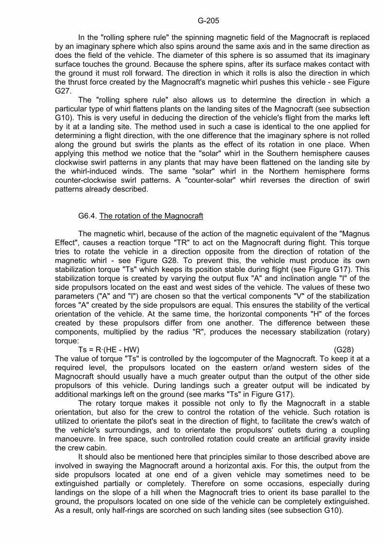
G-205
In the "rolling sphere rule" the spinning magnetic field of the Magnocraft is replaced by an imaginary sphere which also spins around the same axis and in the same direction as does the field of the vehicle. The diameter of this sphere is so assumed that its imaginary surface touches the ground. Because the sphere spins, after its surface makes contact with the ground it must roll forward. The direction in which it rolls is also the direction in which the thrust force created by the Magnocraft's magnetic whirl pushes this vehicle - see Figure G27. The "rolling sphere rule" also allows us to determine the direction in which a particular type of whirl flattens plants on the landing sites of the Magnocraft (see subsection G10). This is very useful in deducing the direction of the vehicle's flight from the marks left by it at a landing site. The method used in such a case is identical to the one applied for determining a flight direction, with the one difference that the imaginary sphere is not rolled along the ground but swirls the plants as the effect of its rotation in one place. When applying this method we notice that the "solar" whirl in the Southern hemisphere causes clockwise swirl patterns in any plants that may have been flattened on the landing site by the whirl-induced winds. The same "solar" whirl in the Northern hemisphere forms counter-clockwise swirl patterns. A "counter-solar" whirl reverses the direction of swirl patterns already described. G6.4. The rotation of the Magnocraft The magnetic whirl, because of the action of the magnetic equivalent of the "Magnus Effect", causes a reaction torque "TR" to act on the Magnocraft during flight. This torque tries to rotate the vehicle in a direction opposite from the direction of rotation of the magnetic whirl - see Figure G28. To prevent this, the vehicle must produce its own stabilization torque "Ts" which keeps its position stable during flight (see Figure G17). This stabilization torque is created by varying the output flux "A" and inclination angle "I" of the side propulsors located on the east and west sides of the vehicle. The values of these two parameters ("A" and "I") are chosen so that the vertical components "V" of the stabilization forces "A" created by the side propulsors are equal. This ensures the stability of the vertical orientation of the vehicle. At the same time, the horizontal components "H" of the forces created by these propulsors differ from one another. The difference between these components, multiplied by the radius "R", produces the necessary stabilization (rotary) torque: Ts = R·(HE - HW) (G28) The value of torque "Ts" is controlled by the logcomputer of the Magnocraft. To keep it at a required level, the propulsors located on the eastern or/and western sides of the Magnocraft should usually have a much greater output than the output of the other side propulsors of this vehicle. During landings such a greater output will be indicated by additional markings left on the ground (see marks "Ts" in Figure G17). The rotary torque makes it possible not only to fly the Magnocraft in a stable orientation, but also for the crew to control the rotation of the vehicle. Such rotation is utilized to orientate the pilot's seat in the direction of flight, to facilitate the crew's watch of the vehicle's surroundings, and to orientate the propulsors' outlets during a coupling manoeuvre. In free space, such controlled rotation could create an artificial gravity inside the crew cabin. It should also be mentioned here that principles similar to those described above are involved in swaying the Magnocraft around a horizontal axis. For this, the output from the side propulsors located at one end of a given vehicle may sometimes need to be extinguished partially or completely. Therefore on some occasions, especially during landings on the slope of a hill when the Magnocraft tries to orient its base parallel to the ground, the propulsors located on one side of the vehicle can be completely extinguished. As a result, only half-rings are scorched on such landing sites (see subsection G10).
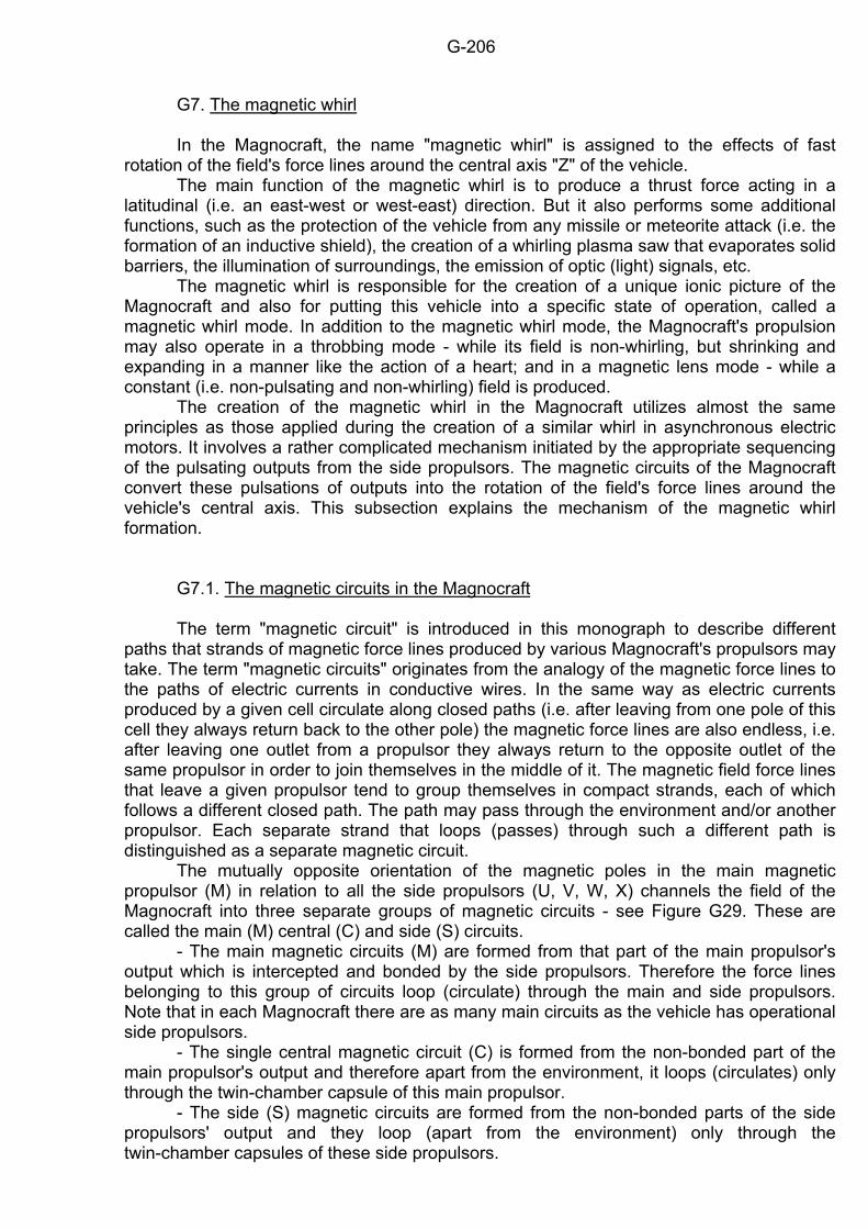
G-206
G7. The magnetic whirl In the Magnocraft, the name "magnetic whirl" is assigned to the effects of fast rotation of the field's force lines around the central axis "Z" of the vehicle. The main function of the magnetic whirl is to produce a thrust force acting in a latitudinal (i.e. an east-west or west-east) direction. But it also performs some additional functions, such as the protection of the vehicle from any missile or meteorite attack (i.e. the formation of an inductive shield), the creation of a whirling plasma saw that evaporates solid barriers, the illumination of surroundings, the emission of optic (light) signals, etc. The magnetic whirl is responsible for the creation of a unique ionic picture of the Magnocraft and also for putting this vehicle into a specific state of operation, called a magnetic whirl mode. In addition to the magnetic whirl mode, the Magnocraft's propulsion may also operate in a throbbing mode - while its field is non-whirling, but shrinking and expanding in a manner like the action of a heart; and in a magnetic lens mode - while a constant (i.e. non-pulsating and non-whirling) field is produced. The creation of the magnetic whirl in the Magnocraft utilizes almost the same principles as those applied during the creation of a similar whirl in asynchronous electric motors. It involves a rather complicated mechanism initiated by the appropriate sequencing of the pulsating outputs from the side propulsors. The magnetic circuits of the Magnocraft convert these pulsations of outputs into the rotation of the field's force lines around the vehicle's central axis. This subsection explains the mechanism of the magnetic whirl formation. G7.1. The magnetic circuits in the Magnocraft The term "magnetic circuit" is introduced in this monograph to describe different paths that strands of magnetic force lines produced by various Magnocraft's propulsors may take. The term "magnetic circuits" originates from the analogy of the magnetic force lines to the paths of electric currents in conductive wires. In the same way as electric currents produced by a given cell circulate along closed paths (i.e. after leaving from one pole of this cell they always return back to the other pole) the magnetic force lines are also endless, i.e. after leaving one outlet from a propulsor they always return to the opposite outlet of the same propulsor in order to join themselves in the middle of it. The magnetic field force lines that leave a given propulsor tend to group themselves in compact strands, each of which follows a different closed path. The path may pass through the environment and/or another propulsor. Each separate strand that loops (passes) through such a different path is distinguished as a separate magnetic circuit. The mutually opposite orientation of the magnetic poles in the main magnetic propulsor (M) in relation to all the side propulsors (U, V, W, X) channels the field of the Magnocraft into three separate groups of magnetic circuits - see Figure G29. These are called the main (M) central (C) and side (S) circuits. - The main magnetic circuits (M) are formed from that part of the main propulsor's output which is intercepted and bonded by the side propulsors. Therefore the force lines belonging to this group of circuits loop (circulate) through the main and side propulsors. Note that in each Magnocraft there are as many main circuits as the vehicle has operational side propulsors. - The single central magnetic circuit (C) is formed from the non-bonded part of the main propulsor's output and therefore apart from the environment, it loops (circulates) only through the twin-chamber capsule of this main propulsor. - The side (S) magnetic circuits are formed from the non-bonded parts of the side propulsors' output and they loop (apart from the environment) only through the twin-chamber capsules of these side propulsors.
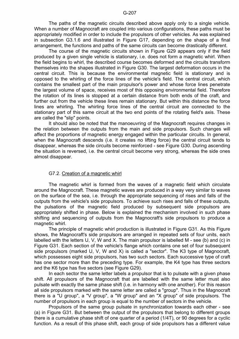
G-207
The paths of the magnetic circuits described above apply only to a single vehicle. When a number of Magnocraft are coupled into various configurations, these paths must be appropriately modified in order to include the propulsors of other vehicles. As was explained in subsection G3.1.6 and illustrated in Figure G17, depending on the shape of a final arrangement, the functions and paths of the same circuits can become drastically different. The course of the magnetic circuits shown in Figure G29 appears only if the field produced by a given single vehicle is stationary, i.e. does not form a magnetic whirl. When the field begins to whirl, the described course becomes deformed and the circuits transform themselves into the shapes illustrated in Figure G30. The largest deformation occurs in the central circuit. This is because the environmental magnetic field is stationary and is opposed to the whirling of the force lines of the vehicle's field. The central circuit, which contains the smallest part of the main propulsor's power and whose force lines penetrate the largest volume of space, receives most of this opposing environmental field. Therefore the rotation of its lines is stopped at a certain distance from both ends of the craft, and further out from the vehicle these lines remain stationary. But within this distance the force lines are whirling. The whirling force lines of the central circuit are connected to the stationary part of this same circuit at the two end points of the rotating field's axis. These are called the "slip" points. It should also be noted that the manoeuvring of the Magnocraft requires changes in the relation between the outputs from the main and side propulsors. Such changes will affect the proportions of magnetic energy engaged within the particular circuits. In general, when the Magnocraft descends (i.e. it creates no lifting force) the central circuit tends to disappear, whereas the side circuits become reinforced - see Figure G30. During ascending the situation is reversed, i.e. the central circuit become very strong, whereas the side ones almost disappear. G7.2. Creation of a magnetic whirl The magnetic whirl is formed from the waves of a magnetic field which circulate around the Magnocraft. These magnetic waves are produced in a way very similar to waves on the surface of the sea, i.e. through the appropriate sequencing of rises and falls of the outputs from the vehicle's side propulsors. To achieve such rises and falls of these outputs, the pulsations of the magnetic field produced by subsequent side propulsors are appropriately shifted in phase. Below is explained the mechanism involved in such phase shifting and sequencing of outputs from the Magnocraft's side propulsors to produce a magnetic whirl. The principle of magnetic whirl production is illustrated in Figure G31. As this Figure shows, the Magnocraft's side propulsors are arranged in repeated sets of four units, each labelled with the letters U, V, W and X. The main propulsor is labelled M - see (b) and (c) in Figure G31. Each section of the vehicle's flange which contains one set of four subsequent side propulsors (marked U, V, W and X) is called a "sector". The K3 type of Magnocraft, which possesses eight side propulsors, has two such sectors. Each successive type of craft has one sector more than the preceding type. For example, the K4 type has three sectors and the K6 type has five sectors (see Figure G29). In each sector the same letter labels a propulsor that is to pulsate with a given phase shift. All propulsors of the Magnocraft that are labelled with the same letter must also pulsate with exactly the same phase shift (i.e. in harmony with one another). For this reason all side propulsors marked with the same letter are called a "group". Thus in the Magnocraft there is a "U group", a "V group", a "W group" and an "X group" of side propulsors. The number of propulsors in each group is equal to the number of sectors in the vehicle. Propulsors of the same group pulsate in synchronization towards each other - see (a) in Figure G31. But between the output of the propulsors that belong to different groups there is a cumulative phase shift of one quarter of a period (1/4T), or 90 degrees for a cyclic function. As a result of this phase shift, each group of side propulsors has a different value
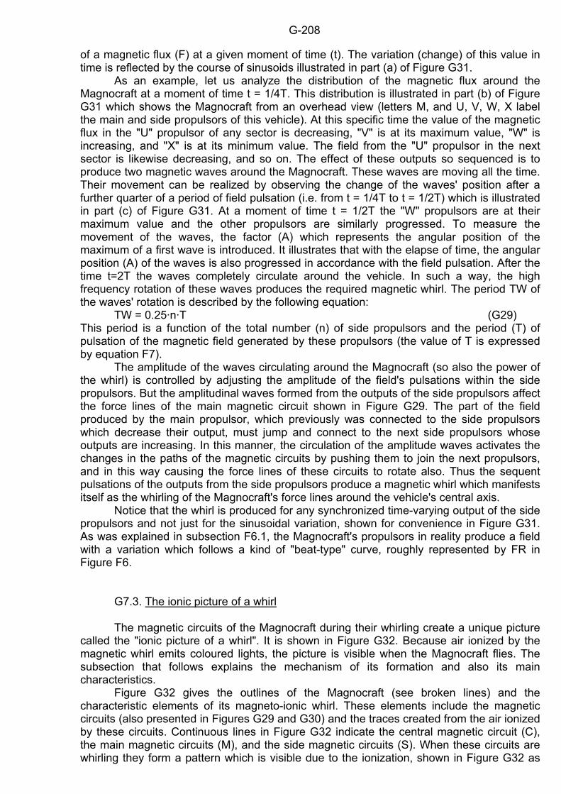
G-208
of a magnetic flux (F) at a given moment of time (t). The variation (change) of this value in time is reflected by the course of sinusoids illustrated in part (a) of Figure G31. As an example, let us analyze the distribution of the magnetic flux around the Magnocraft at a moment of time t = 1/4T. This distribution is illustrated in part (b) of Figure G31 which shows the Magnocraft from an overhead view (letters M, and U, V, W, X label the main and side propulsors of this vehicle). At this specific time the value of the magnetic flux in the "U" propulsor of any sector is decreasing, "V" is at its maximum value, "W" is increasing, and "X" is at its minimum value. The field from the "U" propulsor in the next sector is likewise decreasing, and so on. The effect of these outputs so sequenced is to produce two magnetic waves around the Magnocraft. These waves are moving all the time. Their movement can be realized by observing the change of the waves' position after a further quarter of a period of field pulsation (i.e. from t = 1/4T to t = 1/2T) which is illustrated in part (c) of Figure G31. At a moment of time t = 1/2T the "W" propulsors are at their maximum value and the other propulsors are similarly progressed. To measure the movement of the waves, the factor (A) which represents the angular position of the maximum of a first wave is introduced. It illustrates that with the elapse of time, the angular position (A) of the waves is also progressed in accordance with the field pulsation. After the time t=2T the waves completely circulate around the vehicle. In such a way, the high frequency rotation of these waves produces the required magnetic whirl. The period TW of the waves' rotation is described by the following equation: TW = 0.25·n·T (G29) This period is a function of the total number (n) of side propulsors and the period (T) of pulsation of the magnetic field generated by these propulsors (the value of T is expressed by equation F7). The amplitude of the waves circulating around the Magnocraft (so also the power of the whirl) is controlled by adjusting the amplitude of the field's pulsations within the side propulsors. But the amplitudinal waves formed from the outputs of the side propulsors affect the force lines of the main magnetic circuit shown in Figure G29. The part of the field produced by the main propulsor, which previously was connected to the side propulsors which decrease their output, must jump and connect to the next side propulsors whose outputs are increasing. In this manner, the circulation of the amplitude waves activates the changes in the paths of the magnetic circuits by pushing them to join the next propulsors, and in this way causing the force lines of these circuits to rotate also. Thus the sequent pulsations of the outputs from the side propulsors produce a magnetic whirl which manifests itself as the whirling of the Magnocraft's force lines around the vehicle's central axis. Notice that the whirl is produced for any synchronized time-varying output of the side propulsors and not just for the sinusoidal variation, shown for convenience in Figure G31. As was explained in subsection F6.1, the Magnocraft's propulsors in reality produce a field with a variation which follows a kind of "beat-type" curve, roughly represented by FR in Figure F6. G7.3. The ionic picture of a whirl The magnetic circuits of the Magnocraft during their whirling create a unique picture called the "ionic picture of a whirl". It is shown in Figure G32. Because air ionized by the magnetic whirl emits coloured lights, the picture is visible when the Magnocraft flies. The subsection that follows explains the mechanism of its formation and also its main characteristics. Figure G32 gives the outlines of the Magnocraft (see broken lines) and the characteristic elements of its magneto-ionic whirl. These elements include the magnetic circuits (also presented in Figures G29 and G30) and the traces created from the air ionized by these circuits. Continuous lines in Figure G32 indicate the central magnetic circuit (C), the main magnetic circuits (M), and the side magnetic circuits (S). When these circuits are whirling they form a pattern which is visible due to the ionization, shown in Figure G32 as
G-209
blackened areas. In this ionic picture of a whirl, several characteristic features can be distinguished. The most significant of these are: the central swirling pillar (2), the main swirling block (3), and the flange (4) of side swirling. These features' intensity of colour in the picture depends on the local density of the ionized layer. For example, the curving of the lower part of the main swirling block forms two bulges (5) below the side swirling flange (4). A notable feature of this picture is the "upper slip point" (1) of the central pillar. At this point, the whirling section of force lines of the central circuit (C) meet the stationary section of these lines. Above the slip point the whirling movement of the lines of the central circuit stops. Therefore the air ceases to glow and the circuit becomes invisible. The central circuit also has a "lower slip point" (6), but usually it is concealed behind the main and side swirlings. The ionic picture of a whirl described here may change, depending on the Magnocraft's flight phase and the vehicle's type. The whirl shape illustrated here relates only to a motionless (e.g. landed) craft of a small type (e.g. K3 or K4). But during flight the movement of air changes the shape of the whirl, depending on the orientation of the vehicle in relation to the direction of its flight. Also, other types of Magnocraft (and other configurations) create a slightly different shape of the whirl. Generally, as the "Krotność" factor (see subsection G4.7) increases its value, thus flattening the vehicle's body, also the main swirling block flattens and gradually disappears behind the flange of side swirling. G8. Three modes of the Magnocraft's operation The Magnocraft's magnetic field can be in one of three different states: (1) whirling, (2) throbbing, and (3) constant. Thus depending on the state this field takes, the Magnocraft can operate in one of three possible modes. The subsection that follows describes each of these modes and explains their properties and capabilities. The state of the Magnocraft's field while a magnetic whirl is being produced is called in this monograph the "magnetic whirl mode of operation". The characteristic attribute of this mode is that the side propulsors of the vehicle produce a pulsating magnetic field with a strictly controlled mutual phase shift. A different mode, when the side propulsors of the Magnocraft still produce a pulsating magnetic field but eliminate their mutual phase shift, is called here a "throbbing mode". In the throbbing mode of operation the magnetic whirl is not produced at all. But the field shrinks and expands in a manner similar to the beating of the heart. The pulsating output from the propulsors of the Magnocraft can also be changed into a constant (i.e. non-pulsating) one. In such a case the vehicle's propulsion operates in a "magnetic lens mode". Notice that the Magnocraft's crew may smoothly transform any one of these modes into any other mode. Also, because the parameters of the produced field in this vehicle can be smoothly controlled, there are very flexible possibilities for passing from one mode to any other, when any intensity for each of these modes can be achieved. The most frequently used mode of operation is the magnetic whirl mode. This is because the spinning magnetic field provides the Magnocraft with the latitudinal component of the thrust force, i.e. the component which acts in an east-west or west-east direction. It is necessary to combine this latitudinal component with the meridional component (formed by slanting the propulsors - see subsection G6.2) in order to achieve flights in any other direction except that of precisely meridional ones. (Meridional flights are those which exactly follow the magnetic north-south or south-north direction.) Of course the intensity of the produced magnetic whirl varies depending on the direction of flight and is the strongest for precisely latitudinal flights and decreases gradually when the direction of flight becomes closer to being meridional. For precisely meridional flights the magnetic whirl must be extinguished completely. The throbbing mode of operation has a rather limited use. This is because the throbbing mode allows only for vertical and strictly meridional flights. But it provides the crew with perfect visibility of the vehicle's surroundings. Therefore it is mainly used for purposes of watching or for leisure. Also, as it causes the least damage to the environment,
G-210
it is particularly useful for landing and for take off. Because of the less harmful effects of this mode, for the purpose of landing a special, safer version of it is introduced. This version is called here the "four-circuits" mode of operation. In the four-circuits mode, independently of the type of Magnocraft, only four of its side propulsors are left operational, whereas the output from the rest of them is extinguished (see Figure G29). Practically this means that the vehicle forms only four main magnetic circuits, which affect the environment to a much smaller extent than would be the case when the circuits of all the "n" side propulsors are active (see subsection G10). Of course, the four-circuits mode limits significantly the operational abilities of the Magnocraft therefore it is used almost exclusively for the purposes of landing and take off. The magnetic lens mode of operation, similarly to the throbbing mode, also has limited use as it only allows for strictly meridional and vertical flights. Moreover, it makes it impossible for the crew to observe the environment visually and requires all watching to be conducted with instruments. But because this mode makes the Magnocraft invisible, it can be used in all those cases when the crew does not wish to be noticed (e.g. in all spying and military missions, for the watch of the uninterrupted behaviour of people, or during visits to planets with hostile civilizations). G8.1. Visual recognition of the mode During each mode of the Magnocraft's operation, the attributes of this vehicle (including visual ones) are very different. A summary of these attributes is presented in the next subsections. Only those attributes are examined here which impact on the visual appearance of the Magnocraft. One of the main reasons for which it is vital that people know how to recognize the Magnocraft's mode of operation is safety. In the magnetic whirl mode of operation the Magnocraft is extremely dangerous as it can cause instant death (through the magnetic burning of tissues) of people who approach it, and the melting or inductive explosion of metallic vehicles that come too close. But in the throbbing and magnetic lens mode of operation the Magnocraft is reasonably safe (apart from the direct exposure to the outlets from its propulsors) and can be approached and even touched without fear. Therefore it is important that individuals, as well as special services (police, pilots) are able to easily distinguish between the dangerous and the safe operation of this vehicle (especially in the light of the proof that "UFOs are already operational Magnocraft" presented in chapter J). The mode of the Magnocraft's operation can be determined during a visual sighting of this vehicle or during an examination of its photographs. In the magnetic whirl mode of operation, the vehicle is hidden inside a cloud of ionized air formed by the magnetic whirl. This cloud, when observed by the naked eye or photographed with a long time exposure, displays a number of features characteristic of the ionic picture of a whirl (which are illustrated and explained in Figure G32). If this cloud is photographed with a very short time exposure, the picture reveals only the strands of air ionized within the magnetic circuits - see Figure G30. Notice that such spinning strands of the main magnetic circuit look like streams of water dispersed from a rotating sprinkler. But the direction of the whirl rotation of the Magnocraft's field is opposite from that of the water jets from sprinklers of a similar shape. This is because the motion of the Magnocraft's field is forced at the vehicle's edge, whereas the sprinkler is propelled at its axis. In the throbbing mode of operation the surface of the Magnocraft can be clearly visible. But during poor light conditions, at the outlets from the propulsors and also along the magnetic circuits some glowing areas may be noticed. These glowing areas may take the shape shown in Figure G33, when observed by the naked eye or when photographed with a long time exposure from a motionless spacecraft. It is worth stressing here that because the opposite magnetic poles of the Magnocraft's propulsors cause the ionized air to glow in different colours, patterns shown in Figure G33 allow us to determine the polarity of the vehicle's propulsors. In general, a red-yellow glow is emitted by the air ionized at the
G-211
outlets where the north magnetic pole (N) prevails, whereas a blue-green colour is emitted by the air ionized at the propulsors' outlets where the south magnetic pole (S) prevails. When the Magnocraft moves fast or when it is taken with a short time of exposure, individual pulsations of its magnetic field produce a variety of patterns that reflect a multiple image of the vehicle's circuits. The principles of formation of these multiple images of the Magnocraft's circuits are explained in Figure G34. The shapes of the patterns revealed in such cases depend on many factors, such as the orientation of the craft (i.e. the section of its magnetic circuits directed towards the observer), the direction of its movement, the light and weather conditions, etc. There may occur some problems with recognition of the magnetic lens mode of the Magnocraft's operation, as the vehicle is then completely invisible to the naked eye and undetectable by a radar beam, but slightly registrable (as a kind of unfocussed shape) on a sensitive photographic film. Such photographs only reveal the light produced by the spacecraft itself (i.e. not the light reflected from it) as only this light is able to pass outwards through the magnetic lens. Of course the crew may intentionally eliminate any emission of light from the spacecraft. G8.2. The SUB system for indicating the Magnocraft's mode of operation Because of reasons of safety, the actual mode in which the propulsors of the Magnocraft work must be known not only by the crew of a given vehicle, but also by people on the ground and by crews of any other vehicles which are in the vicinity. This is very important for avoiding accidents, for space traffic control, and for coupling/decoupling activities. Therefore, to indicate the actual state of propulsion, a special system of lamps must be installed in the Magnocraft. This system represents an advanced version of the positional (navigation) lights used in modern aeroplanes. It is called here the "SUB system" from the first letters of its Polish name, "system Sygnalizacji Ukladami Barwnymi". This subsection explains its components, operation, and main functions. The components of the SUB system are shown in Figure G35. It consists of four, or a multiple of four, large signalling lamps (lights) installed around the vehicle's perimeter, usually on the outer tip of its flange, plus a further four small lamps installed on the pilot's control panel in the crew cabin. The large lamps from the vehicle's flange are positioned with equal spacing between themselves. They are marked with the letters U, V, W and X. The four small lights on the pilot's control panel are positioned in a row and marked with the letters ui, vi, wi, and xi. These lights on the control panel are duplicates of the lights on the flange and are installed for the pilot's use; i.e. they light up in an identical manner to the lights from the flange that are marked with a corresponding letter. Each lamp of the SUB system emits the colour of light which corresponds to the variation in the magnetic field of the group of side propulsors marked with the same letter (see Figure G31). Therefore the pattern created by the lights is dependent on the field pulsation in the particular side propulsors. The light emitted by the SUB system has three main colours whose precise shades are closely controlled. These shades within the light's main colour may vary depending on the pole of the magnetic field and the intensity (amplitude) of the field's pulsation. On the other hand, the main colours of the lamps' glow depend on the actual state of the output's amplitude from this group of propulsors which are signalled by a given set of lamps. For example, if the value of a pulsating output in the "U" propulsors reaches the maximum of its amplitude, all the "U" lamps emit red light - see Figure G35. When the value of the field in the "U" propulsors reaches the middle of its amplitude, then all the "U" lights change colour to bright yellow (compare the diagram in Figure G31 with Figure G35). When the value of the field in the "U" propulsors reaches its minimum, the "U" lamps emit a blue colour. In a similar manner colours also change in the lamps that reflect the output from the "V", "W" and "X" groups of propulsors. The above explanation illustrates that the changing of colours in each light is a visual indication of the field variation of the particular group of propulsors. Thus the SUB lights
G-212
give complete information about the state of the vehicle's magnetic field. They indicate the mode of operation of the propulsors (by showing: the rotation of colours for the magnetic whirl mode, the stationary on/off flashing for the throbbing mode, or the continuous one colour glow for the magnetic lens mode of the propulsors' operation), the direction of whirl rotation (by the direction in which given colours apparently move), the orientation of the magnetic poles (which colour is dominant), the amplitude of pulsation (by differentiation between the depths of the colours at extreme points of pulses), and the level of the constant component in the propulsors' output (by a mean shade of main colours). So in this way the lights of the SUB system warn the crews of other vehicles and people on the ground about the field configuration and parameters that prevail around a given Magnocraft. It is vital that ordinary people also learn to recognize these warnings (see also subsection J2.9). G9. The properties of the Magnocraft The Magnocraft is an unusual vehicle. Its completion will introduce to our civilization a technological advancement that has never occurred before. This craft will send us to the stars and carry us to the centre of the Earth, will fly with a speed close to the speed of light or will hover motionless over our gardens, will save countless lives but can also be used as a tool of destruction. The unique operation of the Magnocraft is the source of its unusual properties. Many of these are unknown to us, as no other human device has previously been able to create them. Such attributes as the magnetic framework, inductive shield, magnetic whirl, plasma saw, vacuum bubble, magnetic lens, etc., are completely unfamiliar, so they may be difficult to comprehend as many people have no frame of reference to which these properties could be compared. The descriptions that follow reveal the basic attributes of the Magnocraft as it appears in all three modes of operation. It should be stressed that these are very brief descriptions, and that the limited size of this monograph forces the author to introduce short cuts in the explanations provided. But further details can be deducted from the material presented here. Also the author welcomes questions, inquiries, and comments concerning any part of this monograph. G9.1. The properties of the Magnocraft during the magnetic whirl mode of operation The powerful whirling magnetic field creates a circular electrical field around the Magnocraft's surface which sweeps away any ionized molecules present in the air. These molecules collide with one another, causing cumulative ionization of the air near the vehicle, and creating a plasma whirl which follows the whirling magnetic field. So the first property caused by the magnetic whirl is a plasma whirl which also circulates around the Magnocraft's surface. This swirled plasma creates an ionic picture of the whirl which is explained in subsection G7.3. The particles from the plasma whirl that rotate around the vehicle are acted upon by centrifugal forces. These forces cause the rejection of air from the Magnocraft's surface and the creation of a local vacuum bubble around its body. So when the Magnocraft flies in the air or water, it in fact flies in a small hole of the local vacuum that it created around itself. This vacuum bubble eliminates viscous friction between the craft and the atmosphere, making it possible to reach speeds much higher than would normally be possible because of the heat barrier. A rough estimation of these speeds gives the value of around 70,000 km per hour in the air, and about 800 kilometers per hour for flights under water. In free space away from the atmosphere, this vehicle can attain a speed only a small fraction of a percent smaller than the speed of light. The second important property of the Magnocraft is the elimination of sound waves by the plasma whirl. This principle involves the breaking of the pressure cone which is
G-213
formed in front of all flying vehicles and which is the source of sound caused by their flight. This enables the Magnocraft to fly noiselessly. Air plasma emits a light. Therefore the third property is the emission of a strong incandescent light from the ionized air. In the magnetic whirl mode of operation, the body of the Magnocraft is completely hidden inside a ionized cloud. For precise manoeuvring in this mode, it is necessary to use special periscopes (see (1) in Figure G5) which extend beyond the range of the ionized air. Because the main constituents of air are nitrogen and oxygen, whose ions glow red, yellow, green and violet, depending on the conditions, these colours are dominant in the plasma cloud produced around the Magnocraft. High energy plasma can destroy all hard materials, as is shown in the application of plasma lancets. Therefore the plasma whirl of a Magnocraft forms a kind of circular saw of enormous power, which in this monograph is called the "plasma saw". This plasma saw provides another property, whereby the vehicle is able to cut into the hardest rock and tunnel through it. During these flights of the Magnocraft through solid materials, such as rocks, buildings or machinery, it leaves behind tunnels with a geometrical shape and vitreous surface - see Figure G36. The attributes of these tunnels are described in the subsection that follows. Both the whirling magnetic field of the Magnocraft and the plasma saw that follows it, both create a sort of inductive shield that protects the vehicle from outside attack. Therefore the next property the Magnocraft has is the ability to destroy and repulse any objects in its path which are made of electrical current conductors (such as missiles, aeroplanes, meteorites, or cosmic dust). The destruction of such objects is achieved by inducing in them powerful electric currents that cause the material from these objects to instantly evaporate from the inside until they explode and then burn up in the plasma whirl. Splinters from such exploding objects are porous and full of vapour bubbles. When the distance from the Magnocraft is sufficiently great, the whirling currents induced in any electrical circuits prevent the flow of electrical power. This cuts the circuits off from any electricity supply. In the effect, certain electricity consumers or entire power stations found in the vicinity of such a vehicle, are deprived of their supply of electric power. The magnetic whirl also produces electromagnetic beams which may destroy television transmission, radio connections, telecommunications, etc. G9.1.1. Properties of the tunnels made in rocks by the Magnocraft The properties of the tunnels hollowed out in rock by the Magnocraft's "plasma saw" remain in strict correlation to the principles of operation of this vehicle. This means that the action of each principle applied by the vehicle causes the appearance of a particular set of properties within the tunnel. To highlight this correlation, the main principles of the Magnocraft's operation (indicated by the letters #A, #B, ..., #F) are listed first, followed by the specification of the properties of the tunnels that result from these principles (these subsequent properties are indicated by the numbers 1, 2, ..., 17). #A. The Magnocraft flies in a magnetic (non-aerodynamic) manner, which characteristic features include: following straight lines, rapid (almost right-angle) changes of flight direction without the benefit of a curve radius, and suspending motionlessly in the same position. 1. The tunnels evaporated in rock during flights of this vehicle comprise long, straight sections which are joined together by sharp corners. 2. In locations where the Magnocraft remains motionless, the rounded, drum-shaped caves modelling the magnetic whirl outlines (e.g. the ionic picture of a whirl - see Figure G32) should appear in the middle of these tunnels. These caves should show evidence that the magnetic whirl has removed surrounding rock by vaporization. #B. Propelling and stabilizing forces are obtained by the interaction of the Magnocraft's magnetic field with a field produced by the Earth, planets, Sun, or Galaxy.
G-214
3. Disturbances in the direction of the Earth's magnetic field should be frozen in the rocks surrounding the tunnels (a magnetic compass used within the tunnels can register false readings, varying directions from place to place). #C. During its flight the saucer-shaped Magnocraft must all the time be oriented in the same direction, i.e. in such a manner that its base remains almost perpendicular to the local course of the force lines of the Earth's magnetic field. Therefore, depending on which direction it flies, the shape of the tunnels that it leaves behind must either reflect the vehicle's circular overhead outline or its triangular side outline. 4. When the Magnocraft flies in the direction of magnetic north-to-south or south-to-north, the shape of the tunnels is elliptical in cross-section. The long axis of this ellipse is horizontal, and the ratio of the long to the short axis is proportional to the inclination angle of the Earth's magnetic field (i.e. on the magnetic equator the tunnels should be circular in cross-section) - see Fig. G36 "b". 5. When the Magnocraft flies in an east-west or west-east direction, the shape of the tunnels matches the outlines of the saucer (i.e. it roughly resembles the shape of an obtuse triangle) - see Figure G36 "c". 6. When the paths of the tunnels change direction, their shape should change from elliptical into triangular, or vice versa, depending on the geographical direction of the vehicle's course. #D. The tunnels are cut by a saucer-shaped spinning cloud of plasma (i.e. the plasma saw) which tightly surrounds the Magnocraft's body. Thus the appearance of these tunnels must roughly reflect the shape obtained by the intersection of the vehicle with the solid material that surrounds it. 7. The tunnels are geometrically shaped, even, and of a technological appearance. 8. The shape, dimensions, and patterns (ripples) on the walls of the tunnels should remain the same as long as the spacecraft which made them was maintaining an unchanged speed and direction of movement and did not cross the path of another tunnel (i.e. each straight section of the tunnels should look approximately the same along its entire length). #E. The rock in the vehicle's path is removed through the melting and evaporation by the plasma saw. 9. The tunnels should have a smooth, glossy surface, resulting from the melting of the rocks by the plasma whirl of the vehicle. 10. The plasma whirl should leave some characteristic, repetitive indentations (ripples) on the surfaces of the tunnels. The shape, course, and intensity of these ripples depend on the mutual positioning of the tunnels' walls and the direction of the whirl rotation. In elliptical tunnels, formed during north-south flights of the Magnocraft, the indentations should take the form of shallow grooves running around the periphery of the tunnel at even distances from one another (the distance between successive grooves depends on the speed of the Magnocraft which produced them). The appearance of these ripples should resemble those left by drilling tools. At the ends of the drum-shaped caves formed by motionless vehicles, the indentations should be shaped in clear spirals whose flutes recede towards the centre of the vehicle's whirl rotation. Such spirals should resemble the shape of a magnetic whirl illustrated in the lowest part of Figure G30. 11. The tunnels should have a rough and craggy apparent floor (the "apparent floor" is the one that can be seen when someone enters these tunnels; the "original floor" is hidden under this apparent one). This should have been created by the falling and subsequent hardening on the original floor, of the rock particles melted during the flight of the Magnocraft. 12. The shape of the tunnels' lowest (original) surface, which is hidden under the layer of hardened rock particles creating an apparent floor of the tunnels, is symmetrical to the shape of the tunnels' ceiling. 13. The thermally induced changes in the crystallographic properties of native rock located close to the tunnel's surface should be detectable. Such changes,
G-215
disappearing at some distance from the tunnel's surface, do not appear in the rocks of the caves created by hydraulic or mechanical interactions. #F. The volume of rocks, evaporated when acted upon by the Magnocraft's plasma whirl, form a kind of super-hot, highly compressed vapour which expands along the area of the tunnel created behind the vehicle. 14. The particles of vaporized rock, when hardening on the surfaces of the tunnel (especially on its floor), must form a monotropic structure whose arrangement reflects the direction of movement of this medium. 15. At shallow locations of the long tunnels, the expanding gases cause breaches to the land's surface (see "2" in Figure G36). These breaches and cracks take advantage of the occasional weak spots within native rock and can be formed at random without displaying any regularity in shape or course. 16. At crossing points of the tunnels the movement of expanding vapors creates hardening drifts which may block the entrance to the tunnel which had been made earlier. 17. Particles of hardened vaporized rock should be spread over a wide area in the vicinity of the entrance (not the exit) to a tunnel, i.e. the place where the Magnocraft descended below the surface of the ground, as well as in the vicinity of the outlets from breaches formed by the expansion of vapour from a long and shallow tunnel. The effects caused by this should be similar to the raining down of volcanic ash after a small eruption. * * * It should be mentioned here that numerous tunnels which display properties exactly corresponding to those listed above have already been found on Earth. Examples are listed and discussed in subsection M2. G9.2. The properties of the Magnocraft during the throbbing mode of operation During the throbbing mode of the Magnocraft's operation, most of the properties characteristic for the magnetic whirl mode disappear. Thus the vehicle becomes safe and non-destructive. But also the latitudinal component of the thrust force no longer exists. The Magnocraft in this mode is only able to fly vertically and in the direction of the meridian. Because the magnetic whirl does not exist, the cloud of luminous air disappears as well. Thus, during daylight, watching of the Magnocraft's surface is possible (in this mode the Magnocraft's crew are also able to observe visually i.e. without any instruments the vehicle's environment). Because there is a local air ionization at the outlets from the propulsors (see Figure G33), some glowing areas can be visible on a cloudy day and at night. As the magnetic field separates the ions, the light from these areas has two different colours, depending on the field's dominant pole. Near the north (N) pole of each propulsor, the light is red-yellow, whereas near the south (S) magnetic pole of the propulsors, it is blue-green (see Figure G33). The pulsating field generated by the Magnocraft during the throbbing mode has some characteristics similar to the field in our electricity transformers. Therefore in this mode electrical currents are induced in every closed circuit which is present in the field's range. This is especially effective where there is a transformer at the beginning of the circuit. Thus the nearby flight of the Magnocraft may cause the activation of radio and television sets and other items of electrical equipment (e.g. commutator electric motors) which are disconnected from the electrical power supply. It should be noticed that the effect of the Magnocraft acting in this throbbing mode on electrical equipment is opposite from the magnetic whirl mode, when electrical devices cease working because they are cut off from the electricity supply. G9.3. Humming noises appearing in both the magnetic whirl and throbbing modes of operation
G-216
There exists also a number of effects caused by the Magnocraft, independently of whichever mode of operation described above is in force. The most common of these are "humming noises". These noises are similar to the buzzing of high voltage transformers, but with a higher tone (rather like a flying bumblebee) because of the higher frequency of field pulsation. The generating of such sounds depends on the inducing of electrical currents in conductive objects found within the range of the pulsating field. The currents around these conductive objects produce their own magnetic field which interacts with the Magnocraft's pulsating field, and as a result the objects vibrate at the same frequency as the vehicle's pulsating field. Accordingly, these sound waves are produced by the conductive objects which are present in the Magnocraft's environment, not by the Magnocraft itself (this vehicle is made of material which is resistant to the induction of currents). Some people may develop a hyper-sensitivity of a nerve inside their ears which allows them to perceive the magnetic vibrations of a Magnocraft at a long distance (people who at some stage find themselves very close to an operational Magnocraft can be especially sensitive). These people may hear humming sounds when a Magnocraft approaches, even if they can't see it and no one else hears any noise. Although in the majority of cases these people may believe that the noises they unexpectedly experience result from an unrecognized medical problem, knowledge of their capability can be extremely useful as it gives them (and other people nearby) a remote sensing of the approaching Magnocraft. G9.4. The properties of the Magnocraft during the magnetic lens mode of operation The Magnocraft's Oscillatory Chambers can also be so controlled that they produce a constant (i.e. non-pulsating) and stable magnetic field - see subsection F6.1. In such a case the vehicle displays a manoeuvrability identical to that present during the throbbing mode of operation (i.e. it is only capable of meridional and vertical flights), but it forms additionally the so-called "magnetic lens". By the term "magnetic lens" the combination of two different optical effects is described. The first and the most significant of these is bending the path of light with the energy density of the vehicle's concentrated magnetic field. This effect originates from the equivalence of mass to energy (i.e. from the famous equation: E = m·c2) expressed by the theory of general relativity. The enormous concentration of energy within the Magnocraft's field (see subsection G5.5) is equivalent to the concentration of additional transparent matter around the vehicle's surface. This matter, although it is invisible, increases the "density" of the air, thus changing its optical properties. An effect of this is similar to surrounding the Magnocraft with a thick layer of invisible glass which has an index of refraction different from that of air. Therefore, the electromagnetic radiation entering the range of the vehicle's dense field must be deflected significantly. Such deflection can be comparable to that caused by optical lenses. The second effect that contributes to the formation of the magnetic lens results from the monotropic nature of magnetic fields. This nature causes that in magnetic fields of extreme density light can only pass along the fields' force lines, but is stopped or bent when passing across these lines. This causes the Magnocraft to have a tendency to bend light so that it follows the path of their magnetic circuits. The magnetic lens allows the Magnocraft's crew to make the vehicle completely invisible to radar detection and to the naked eye. It also deflects the beams of military lasers from targets, shields the crew from the action of electromagnetic radiation caused by a nuclear explosion, screens the vehicle from heat radiation, etc. Therefore it makes the Magnocraft not only invisible, but also indestructible by any high-energy emissions. Contrary to the optical lenses, the magnetic lens does not have any clearly distinguishable surfaces that may reflect light. It displays a transparency identical to that of air, but its mass density and saturation of space with magnetic force lines gradually change.
G-217
Therefore the magnetic lens may remain unnoticeable even if an observer is only a few meters from it. The complete version of the magnetic lens appears only when the Magnocraft produces a constant (i.e. non-pulsating) magnetic field. However, when other types of field surround this vehicle (especially the throbbing one) a partial magnetic lens effect can also be created. In such cases the light bends near the outlets from the vehicle's propulsors, thus distorting the apparent shape of the Magnocraft's shell. There is also a special case when such a partial effect of a magnetic lens becomes highly noticeable. This case reveals itself when a Magnocraft ascends. Because it represents one of the most common occasions when the action of a magnetic lens becomes obvious to outside observers, it requires a separate explanation. G9.4.1. The magnetic lens action in ascending Magnocraft The central magnetic circuits of ascending Magnocraft produce a unique magnetic-lens effect based on the course of magnetic force lines. This effect facilitates the visual watching of twin-chamber capsules from the main propulsors of these vehicles, but obstructs the visibility of remaining parts of these vehicles. Thus it allows outside observers to see and precisely describe the main twin-chamber capsule from the Magnocraft, and even to photograph this capsule. The mechanism involved in producing this particular magnetic-lens effect is as follows. In the ascending Magnocraft, the power of a magnetic field involved in the vehicle's central magnetic circuit exceeds many times the power involved in the main and side circuits. For this reason force lines of the central magnetic circuit hermetically surround not only the entire body of such an ascending vehicle, but also its main and side magnetic circuits which become wrapped into a kind of a magnetic doughnut (i.e. looping magnetic force lines). Principles involved in the formation of this doughnut are illustrated in Figure G37. As was stressed in the previous subsection, the extremely concentrated magnetic field of the Magnocraft interferes with light. This interference manifests itself most evidently by allowing the light to pass easily along the field force lines, but bending the paths of the light which try to pass across these lines. The above mentioned magnetic doughnut formed around the ascending Magnocraft means that to reach the vehicle's shell, the light would need to pass across the doughnut's field force lines. Therefore anything contained inside this donut becomes invisible to an observer looking from underneath, as the picture of it (i.e. light reflected from it) would need to cross the field - see path (1) in Figure G37. But in order to reach the main propulsor, the light needs to follow these lines - see path (2) in Figure G37. For this reason, outside witnesses who observe such an ascending Magnocraft can easily see a twin-chamber capsule from the main propulsor, but they are unable to see any other part of the vehicle's shell. While looking at an ascending Magnocraft, these people notice that at a certain angle the entire sides of the vehicle gradually disappear from view, and the only element remaining visible becomes a small "diamond-shaped" device located in the centre of the vehicle. This device is in fact the twin-chamber capsule from the vehicle's main magnetic propulsor (some witnesses, unaware of the principles described here, can wrongly take this "diamond" for a new kind of vehicle whose shape differs from that of the Magnocraft). The cubical edges of this capsule, when looked at from an angle, take the shape of a diamond. Notice that the situation described above changes drastically when the Magnocraft terminate their ascent. While they are hovering or descending, their main magnetic circuits stop being dominant over other circuits, thus the entire vehicle must appear visible again to observers. G10. The landing sites of the Magnocraft
G-218
When a vehicle contacts the solid ground it must leave recognizable marks. For example, the wheels of a car leave rather characteristic tracks, whereas a hovercraft produces a band of swirled and flattened vegetation. The Magnocraft's propulsion utilizes a very powerful magnetic field which is capable of cooking the soil in a manner similar to that utilized in microwave ovens. Therefore when the Magnocraft lands, its propulsors must also scorch on the ground a number of distinctive marks. These marks can provide vital information about the vehicle which produced them. They reflect the type of vehicle, its orientation, configuration, mode of operation, etc. To enable the correct interpretation of such marks, the subsection that follows is devoted to the description of the main attributes of the Magnocraft's landing sites. It is worth emphasizing here that the popular understanding of the term "landing" is inspired by the operation of helicopters and aeroplanes. These machines lead us to believe that if a flying vehicle lands, the burning of its fuel must be shut down and its propulsion system must go into a dead, passive state. However the principles of the Magnocraft's operation are more like those of a balloon or airship than those of our helicopters or aircraft. Therefore when applying the term "landing" to the Magnocraft, consideration must be given to the fact that this vehicle does not dissipate its energy resources during motionless hovering. Therefore the Magnocraft's landing more involves hovering close to the ground (with its propulsion still remaining operational) so that its crew and passengers are able to leave or enter the deck, rather than an actual "sitting" on the ground and extinguishing of its propelling field. G10.1. Environmental damage caused by the landed Magnocraft Five major categories of environmental damage should be distinguishable in the Magnocraft's landing sites. These categories can be classified as: (1) scorching, (2) biological impact, (3) changes in energy level, (4) chemical changes, and (5) mechanical destruction. The primary cause for all of them is the action of a highly concentrated magnetic field that is yielded from the propulsors of a landed vehicle. But some types of damage appear as the effect of an indirect action of this field, e.g. its ability to produce a highly aggressive ozone that attacks the chemical components of soil and air. Although real landing sites must incorporate the simultaneous action of a number of causes discussed below, for the clarity of analysis this subsection describes separately each major category of damage. 1. Scorching is the most dominant type of damage caused by the magnetic circuits of a landed Magnocraft. It occurs because a highly concentrated magnetic field passes through solid matter. The result is similar to that caused by an over-active microwave oven. In the effect, all organic matter (e.g. plants, animals, insects) in the range of the vehicle's magnetic field is cooked (e.g. wood is completely bleached), incinerated, or turned into brown-gray ash. The non-organic matter (e.g. soil) is parched, demineralized and emaciated. One of the unusual attributes of such magnetic scorching is that it differs in principle from scorching by a fire or by oxidation. Therefore ashes of the organic matter produced during such scorching can be burned later with a high intensity (unlike the ashes from a fire). On the other hand, highly flammable materials that display signs of such scorching do not ignite a fire when the scorching occurs. 2. Biological destabilization is the most noticeable and long-lasting type of environmental damage resulting from the landing of the Magnocraft. It is caused by the extermination of all micro-organisms found in the range of the vehicle's magnetic circuits. Thus, within the former Magnocraft's landing sites, all the parasitic micro-organisms that normally would keep the population of mushrooms under control are killed. The biological effect of such an extermination is an exact equivalent to that of a thermal sterilization of the compost utilized by mushroom growers. Of course after a vehicle ascends, the mushroom spores present in free air instantly take advantage of such ideal growth conditions and take
G-219
over the sterilized soil. The biological balance, once so disturbed, is then extremely difficult to restore. Therefore, within the Magnocraft's former landing sites, an explosive growth of mushrooms is observed which may last for many decades (the author estimates that in the case of non-cultivated soil, the natural restoration of a biological balance at the Magnocraft's landing sites may take over 100 years). Because such a technologically induced growth must outline the circular pattern of the vehicle's propulsors (see Figures G38, G39 and B1), these mushroom circles are called here by their folk name of "fairy rings". It should be stressed that in order to biologically destabilize the soil, the Magnocraft must hover in the same place over a period of time that exceeds the so-called "critical time". This critical time is the duration required for the vehicle's magnetic field to completely cook all micro-organisms from the soil. It can be compared to the minimal time needed to cook a particular product in a microwave oven. For the K3 type of Magnocraft the author estimates this critical time to exceed ten minutes. If a vehicle hovers above a particular landing site shorter than this critical time, then the soil is not destabilized and a long-lasting fairy ring is not established in it. Thus all signs of such a short-duration landing would disappear after only a couple of months. The "fairy rings" produced by the effect of the Magnocraft's long-duration landings must display a number of unique attributes which are absent in natural mushroom growths. The most important of these attributes, which can be used as identification characteristics of the Magnocraft's landing sites, are listed below: (A) The dimensions which exactly correspond to the "d" diameters (nominal) of the vehicles that made them. These "d" diameters are the Magnocraft's equivalent to the widths of wheel tracks made by motor cars - see Figure G23. Thus the nominal diameters of fairy rings, when determined according to the rules described in subsection G10.3.1, must fulfil the equation (G30) and must correspond to the data from column "d" of Table G1. Practically this means that the sizes of fairy rings comprise the terms of a geometric progression with ratio two, and that these rings repeat the binary progression of the "d" diameters from K3 to K10 types of the Magnocraft, i.e. every subsequent ring is twice as big as the previous one. Note that the nominal diameters of the fairy rings depend only on the type of vehicles that produced them, and for the same type they must remain exactly the same independently of: soil conditions; species of mushrooms that populate the landing site; area, country or continent where the sites are found; etc. (B) The repetitive growth in precisely the same locations year after year for many decades. No slow drifting away or transformations, so typical of natural growths, will be observed. (C) Remaining exactly the same size from year to year. Note that if the rings were to grow naturally they would increase their diameter by not less than about 2 metres each year. (D) Remaining in a perfect circular or elliptical shape, independently of soil and topographic conditions that may stimulate a monotropic growth. (E) A complete taking over of the entire sterilized soil by mushroom spawn, as the natural self-defense mechanisms of this soil are totally destroyed by the magnetic circuits of a landed vehicle. Thus, mushroom spawn completely chokes up every pore of the soil, leaving no air or space for parasites and other micro-organisms. Also, if a surface layer of the affected soil is replaced, the spore should take it over again by attacking from below (i.e. the rings are extremely difficult to remove). (F) The underground distribution of mushroom spawn so that it reflects the course of the magnetic circuits of a landed vehicle. This means that inside the soil the pattern formed by spawn must exhibit all the elements characteristic of the Magnocraft's landing site, i.e. must consist of a central patch formed by the main propulsor, which is surrounded by a ring formed by the side propulsors - see Figure G39. Moreover such "fairy rings" may sometimes be accompanied by imprints of the vehicle's legs lying within the circle (if the Magnocraft did not hover just above the ground, but used its legs while landing).
G-220
It should be stressed that the biological consequences of fairy rings involve a variety of effects which are strongly dependable on the season of the year. For example in some seasons (e.g. spring) the mushrooms may stimulate a faster growth of grass, in other seasons (e.g. autumn) they may tend to kill the grass. Because of their ability to heat the soil, such mushroom rings also encourage animals and birds to gather and rest on their surfaces. 3. The increase in energy level causes the damage done to all substances affected by the Magnocraft's magnetic field. It is already established that solid matter exposed to the action of an extremely strong magnetic field changes its energy-related properties and begins to behave in a completely different manner. For example such magnetic impact is already utilized commercially for making a concrete stronger than steel, for producing a non-destructible rubber, for growing monocrystals, etc. In the Magnocraft's landing sites it must similarly affect the environment, changing the properties of the soil in a way that may last for many years. The changes in energy level of the soil affected by a landed Magnocraft should be detectable by a number of instruments and techniques. The most simple of these techniques involves the measurement of the electric resistance of the affected soil with an ordinary "ohmmeter". This resistance should be many times higher than the resistance of the non-affected soil from the same landing site. (Note that ordinary soil that is only affected by mushroom spore while its energy level remains unchanged has its electric resistance much smaller than from the same soil which is free of mushrooms.) Similarly, X-ray diffraction techniques should produce results that differ from those for non-affected soil. The increased energy level of the soil must also be manifested through the changes to its inter-particle (surface) tension. This means that the soil affected by the Magnocraft's field refuses to absorb water. Thus the ordinary measurements of the water absorption capability (or humidity) of such soil should provide results that differ from those of unaffected soil. The action of a turbulent magnetic field on the soil should also alter its magnetic properties (e.g. polarity and the level of magnetization). Thus sensitive magnetometers should indicate anomalies in readings at the Magnocraft's landing sites. Finally, the exposure to a highly concentrated magnetic energy together with the bombardment by air ions may also cause short-term radioactivity of the landing site. This radioactivity should be registrable by various radiometers and radiation detectors. 4. Chemical changes are the next type of damage appearing at the Magnocraft's landing sites. These changes involve highly complex phenomena occurring in two steps. In the first step, circuits of the vehicle's magnetic field act on the particles of oxygen found in the field's range and transform this oxygen into a highly active ozone. In the second step, the ozone so obtained attacks all substances in the vicinity, producing a mixture of chemical products (usually various salts). Then these chemical products either fill up pores existing within the soil (if the ozone was formed within the soil), or fall down covering the surface of the scorched marks (if the ozone was formed in free air above the ground). 5. Mechanical destruction is the last category of damage caused by a landed Magnocraft. Three forms of destruction originating from the vehicle's magnetic field can be classified into this category, i.e. (a) flattening of plants, (b) soil compression, and (c) soil extraction. In addition, the mechanical damage can also be caused by various parts of the vehicle (e.g. its legs) which touch the ground. But because the damage from such parts is rather obvious, elaboration here would be unnecessary and so is omitted. (a) Flattening of plants can be caused by two different mechanisms. The first of these involves the spinning magnetic circuits of a vehicle. It appears in the sites where the Magnocraft hovered at a low height only for a very short duration (i.e. shorter than the "critical time"). In such cases the vehicle's field had insufficient time to scorch the vegetation, but spinning magnetic circuits exerted enough force to push down every single blade of grass. The strands of force lines of these circuits act like huge combs that brush down thoroughly all vegetation within the circuits' path. A characteristic attribute of sites formed in such a manner is that all the blades of grass (or crops) are flattened with astonishing precision. They all lie down parallel to each other, perfectly straight and evenly
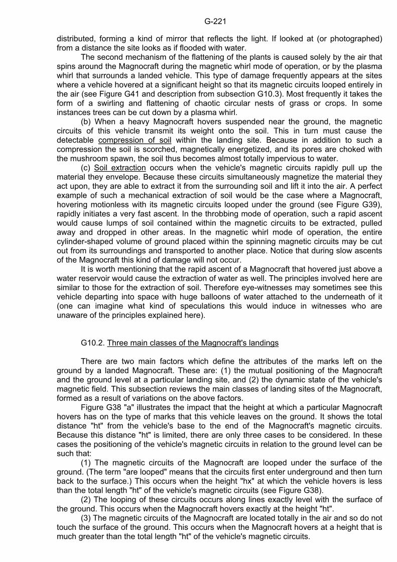
G-221
distributed, forming a kind of mirror that reflects the light. If looked at (or photographed) from a distance the site looks as if flooded with water. The second mechanism of the flattening of the plants is caused solely by the air that spins around the Magnocraft during the magnetic whirl mode of operation, or by the plasma whirl that surrounds a landed vehicle. This type of damage frequently appears at the sites where a vehicle hovered at a significant height so that its magnetic circuits looped entirely in the air (see Figure G41 and description from subsection G10.3). Most frequently it takes the form of a swirling and flattening of chaotic circular nests of grass or crops. In some instances trees can be cut down by a plasma whirl. (b) When a heavy Magnocraft hovers suspended near the ground, the magnetic circuits of this vehicle transmit its weight onto the soil. This in turn must cause the detectable compression of soil within the landing site. Because in addition to such a compression the soil is scorched, magnetically energetized, and its pores are choked with the mushroom spawn, the soil thus becomes almost totally impervious to water. (c) Soil extraction occurs when the vehicle's magnetic circuits rapidly pull up the material they envelope. Because these circuits simultaneously magnetize the material they act upon, they are able to extract it from the surrounding soil and lift it into the air. A perfect example of such a mechanical extraction of soil would be the case where a Magnocraft, hovering motionless with its magnetic circuits looped under the ground (see Figure G39), rapidly initiates a very fast ascent. In the throbbing mode of operation, such a rapid ascent would cause lumps of soil contained within the magnetic circuits to be extracted, pulled away and dropped in other areas. In the magnetic whirl mode of operation, the entire cylinder-shaped volume of ground placed within the spinning magnetic circuits may be cut out from its surroundings and transported to another place. Notice that during slow ascents of the Magnocraft this kind of damage will not occur. It is worth mentioning that the rapid ascent of a Magnocraft that hovered just above a water reservoir would cause the extraction of water as well. The principles involved here are similar to those for the extraction of soil. Therefore eye-witnesses may sometimes see this vehicle departing into space with huge balloons of water attached to the underneath of it (one can imagine what kind of speculations this would induce in witnesses who are unaware of the principles explained here). G10.2. Three main classes of the Magnocraft's landings There are two main factors which define the attributes of the marks left on the ground by a landed Magnocraft. These are: (1) the mutual positioning of the Magnocraft and the ground level at a particular landing site, and (2) the dynamic state of the vehicle's magnetic field. This subsection reviews the main classes of landing sites of the Magnocraft, formed as a result of variations on the above factors. Figure G38 "a" illustrates the impact that the height at which a particular Magnocraft hovers has on the type of marks that this vehicle leaves on the ground. It shows the total distance "ht" from the vehicle's base to the end of the Magnocraft's magnetic circuits. Because this distance "ht" is limited, there are only three cases to be considered. In these cases the positioning of the vehicle's magnetic circuits in relation to the ground level can be such that: (1) The magnetic circuits of the Magnocraft are looped under the surface of the ground. (The term "are looped" means that the circuits first enter underground and then turn back to the surface.) This occurs when the height "hx" at which the vehicle hovers is less than the total length "ht" of the vehicle's magnetic circuits (see Figure G38). (2) The looping of these circuits occurs along lines exactly level with the surface of the ground. This occurs when the Magnocraft hovers exactly at the height "ht". (3) The magnetic circuits of the Magnocraft are located totally in the air and so do not touch the surface of the ground. This occurs when the Magnocraft hovers at a height that is much greater than the total length "ht" of the vehicle's magnetic circuits.
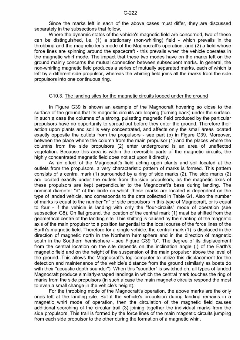
G-222
Since the marks left in each of the above cases must differ, they are discussed separately in the subsections that follow. Where the dynamic states of the vehicle's magnetic field are concerned, two of these can be distinguished, i.e. (1) a stationary (non-whirling) field - which prevails in the throbbing and the magnetic lens mode of the Magnocraft's operation, and (2) a field whose force lines are spinning around the spacecraft - this prevails when the vehicle operates in the magnetic whirl mode. The impact that these two modes have on the marks left on the ground mainly concerns the mutual connection between subsequent marks. In general, the non-whirling magnetic field produces a series of mutually separated marks, each of which is left by a different side propulsor, whereas the whirling field joins all the marks from the side propulsors into one continuous ring. G10.3. The landing sites for the magnetic circuits looped under the ground In Figure G39 is shown an example of the Magnocraft hovering so close to the surface of the ground that its magnetic circuits are looping (turning back) under the surface. In such a case the columns of a strong, pulsating magnetic field produced by the particular propulsors have no opportunity to spread out before they enter the ground. Therefore their action upon plants and soil is very concentrated, and affects only the small areas located exactly opposite the outlets from the propulsors - see part (b) in Figure G39. Moreover, between the place where the column from the main propulsor (1) and the places where the columns from the side propulsors (2) enter underground is an area of unaffected vegetation. Because this area is within the reversible parts of the magnetic circuits, the highly concentrated magnetic field does not act upon it directly. As an effect of the Magnocraft's field acting upon plants and soil located at the outlets from the propulsors, a very characteristic pattern of marks is formed. This pattern consists of a central mark (1) surrounded by a ring of side marks (2). The side marks (2) are located exactly under the outlets from the side propulsors, as the magnetic axes of these propulsors are kept perpendicular to the Magnocraft's base during landing. The nominal diameter "d" of the circle on which these marks are located is dependent on the type of landed vehicle, and corresponds to the data collected in Table G1. Also the number of marks is equal to the number "n" of side propulsors in this type of Magnocraft, or is equal to four - if the vehicle is landing with only the "four-circuits" mode of operation (see subsection G8). On flat ground, the location of the central mark (1) must be shifted from the geometrical centre of the landing site. This shifting is caused by the slanting of the magnetic axis of the main propulsor to a position tangential to the local course of the force lines of the Earth's magnetic field. Therefore for a single vehicle, the central mark (1) is displaced in the direction of magnetic north in the Northern hemisphere and in the direction of magnetic south in the Southern hemisphere - see Figure G39 "b". The degree of its displacement from the central location on the site depends on the inclination angle (I) of the Earth's magnetic field and on the height of the suspension of the main propulsor above the level of the ground. This allows the Magnocraft's log computer to utilize this displacement for the detection and maintenance of the vehicle's distance from the ground (similarly as boats do with their "acoustic depth sounder"). When this "sounder" is switched on, all types of landed Magnocraft produce similarly-shaped landings in which the central mark touches the ring of marks from the side propulsors (in such a case the main magnetic circuits respond the most to even a small change in the vehicle's height). For the throbbing mode of the Magnocraft's operation, the above marks are the only ones left at the landing site. But if the vehicle's propulsion during landing remains in a magnetic whirl mode of operation, then the circulation of the magnetic field causes additional scorching of the circular trail (3) joining together the individual marks from the side propulsors. This trail is formed by the force lines of the main magnetic circuits jumping from each side propulsor to the other during the formation of a magnetic whirl.
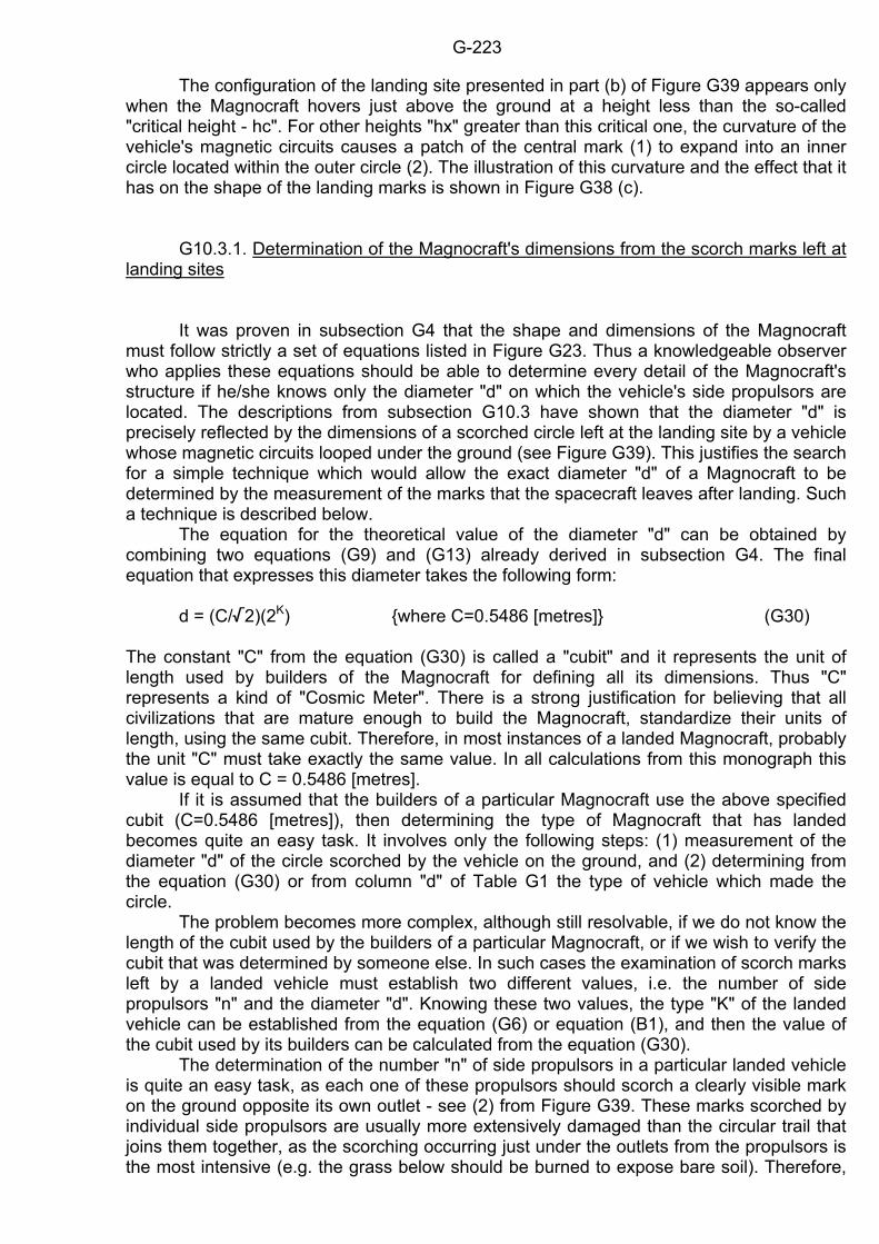
G-223
The configuration of the landing site presented in part (b) of Figure G39 appears only when the Magnocraft hovers just above the ground at a height less than the so-called "critical height - hc". For other heights "hx" greater than this critical one, the curvature of the vehicle's magnetic circuits causes a patch of the central mark (1) to expand into an inner circle located within the outer circle (2). The illustration of this curvature and the effect that it has on the shape of the landing marks is shown in Figure G38 (c). G10.3.1. Determination of the Magnocraft's dimensions from the scorch marks left at landing sites It was proven in subsection G4 that the shape and dimensions of the Magnocraft must follow strictly a set of equations listed in Figure G23. Thus a knowledgeable observer who applies these equations should be able to determine every detail of the Magnocraft's structure if he/she knows only the diameter "d" on which the vehicle's side propulsors are located. The descriptions from subsection G10.3 have shown that the diameter "d" is precisely reflected by the dimensions of a scorched circle left at the landing site by a vehicle whose magnetic circuits looped under the ground (see Figure G39). This justifies the search for a simple technique which would allow the exact diameter "d" of a Magnocraft to be determined by the measurement of the marks that the spacecraft leaves after landing. Such a technique is described below. The equation for the theoretical value of the diameter "d" can be obtained by combining two equations (G9) and (G13) already derived in subsection G4. The final equation that expresses this diameter takes the following form: d = (C//2)(2K) where C=0.5486 [metres] (G30) The constant "C" from the equation (G30) is called a "cubit" and it represents the unit of length used by builders of the Magnocraft for defining all its dimensions. Thus "C" represents a kind of "Cosmic Meter". There is a strong justification for believing that all civilizations that are mature enough to build the Magnocraft, standardize their units of length, using the same cubit. Therefore, in most instances of a landed Magnocraft, probably the unit "C" must take exactly the same value. In all calculations from this monograph this value is equal to C = 0.5486 [metres]. If it is assumed that the builders of a particular Magnocraft use the above specified cubit (C=0.5486 [metres]), then determining the type of Magnocraft that has landed becomes quite an easy task. It involves only the following steps: (1) measurement of the diameter "d" of the circle scorched by the vehicle on the ground, and (2) determining from the equation (G30) or from column "d" of Table G1 the type of vehicle which made the circle. The problem becomes more complex, although still resolvable, if we do not know the length of the cubit used by the builders of a particular Magnocraft, or if we wish to verify the cubit that was determined by someone else. In such cases the examination of scorch marks left by a landed vehicle must establish two different values, i.e. the number of side propulsors "n" and the diameter "d". Knowing these two values, the type "K" of the landed vehicle can be established from the equation (G6) or equation (B1), and then the value of the cubit used by its builders can be calculated from the equation (G30). The determination of the number "n" of side propulsors in a particular landed vehicle is quite an easy task, as each one of these propulsors should scorch a clearly visible mark on the ground opposite its own outlet - see (2) from Figure G39. These marks scorched by individual side propulsors are usually more extensively damaged than the circular trail that joins them together, as the scorching occurring just under the outlets from the propulsors is the most intensive (e.g. the grass below should be burned to expose bare soil). Therefore,
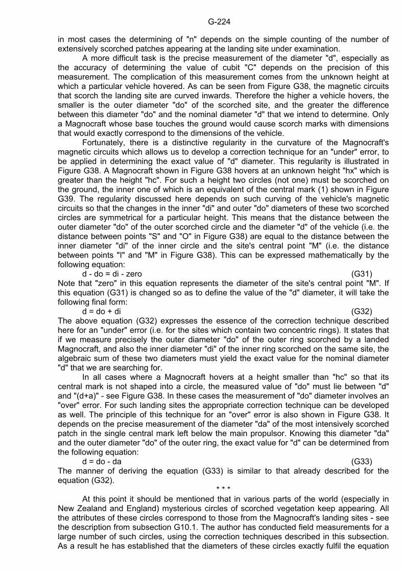
G-224
in most cases the determining of "n" depends on the simple counting of the number of extensively scorched patches appearing at the landing site under examination. A more difficult task is the precise measurement of the diameter "d", especially as the accuracy of determining the value of cubit "C" depends on the precision of this measurement. The complication of this measurement comes from the unknown height at which a particular vehicle hovered. As can be seen from Figure G38, the magnetic circuits that scorch the landing site are curved inwards. Therefore the higher a vehicle hovers, the smaller is the outer diameter "do" of the scorched site, and the greater the difference between this diameter "do" and the nominal diameter "d" that we intend to determine. Only a Magnocraft whose base touches the ground would cause scorch marks with dimensions that would exactly correspond to the dimensions of the vehicle. Fortunately, there is a distinctive regularity in the curvature of the Magnocraft's magnetic circuits which allows us to develop a correction technique for an "under" error, to be applied in determining the exact value of "d" diameter. This regularity is illustrated in Figure G38. A Magnocraft shown in Figure G38 hovers at an unknown height "hx" which is greater than the height "hc". For such a height two circles (not one) must be scorched on the ground, the inner one of which is an equivalent of the central mark (1) shown in Figure G39. The regularity discussed here depends on such curving of the vehicle's magnetic circuits so that the changes in the inner "di" and outer "do" diameters of these two scorched circles are symmetrical for a particular height. This means that the distance between the outer diameter "do" of the outer scorched circle and the diameter "d" of the vehicle (i.e. the distance between points "S" and "O" in Figure G38) are equal to the distance between the inner diameter "di" of the inner circle and the site's central point "M" (i.e. the distance between points "I" and "M" in Figure G38). This can be expressed mathematically by the following equation: d - do = di - zero (G31) Note that "zero" in this equation represents the diameter of the site's central point "M". If this equation (G31) is changed so as to define the value of the "d" diameter, it will take the following final form: d = do + di (G32) The above equation (G32) expresses the essence of the correction technique described here for an "under" error (i.e. for the sites which contain two concentric rings). It states that if we measure precisely the outer diameter "do" of the outer ring scorched by a landed Magnocraft, and also the inner diameter "di" of the inner ring scorched on the same site, the algebraic sum of these two diameters must yield the exact value for the nominal diameter "d" that we are searching for. In all cases where a Magnocraft hovers at a height smaller than "hc" so that its central mark is not shaped into a circle, the measured value of "do" must lie between "d" and "(d+a)" - see Figure G38. In these cases the measurement of "do" diameter involves an "over" error. For such landing sites the appropriate correction technique can be developed as well. The principle of this technique for an "over" error is also shown in Figure G38. It depends on the precise measurement of the diameter "da" of the most intensively scorched patch in the single central mark left below the main propulsor. Knowing this diameter "da" and the outer diameter "do" of the outer ring, the exact value for "d" can be determined from the following equation: d = do - da (G33) The manner of deriving the equation (G33) is similar to that already described for the equation (G32).
* * * At this point it should be mentioned that in various parts of the world (especially in New Zealand and England) mysterious circles of scorched vegetation keep appearing. All the attributes of these circles correspond to those from the Magnocraft's landing sites - see the description from subsection G10.1. The author has conducted field measurements for a large number of such circles, using the correction techniques described in this subsection. As a result he has established that the diameters of these circles exactly fulfil the equation
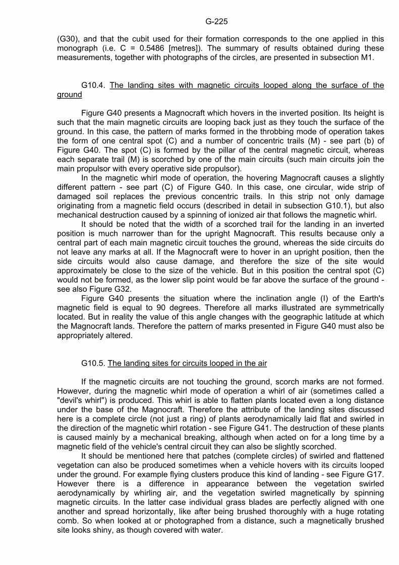
G-225
(G30), and that the cubit used for their formation corresponds to the one applied in this monograph (i.e. C = 0.5486 [metres]). The summary of results obtained during these measurements, together with photographs of the circles, are presented in subsection M1. G10.4. The landing sites with magnetic circuits looped along the surface of the ground Figure G40 presents a Magnocraft which hovers in the inverted position. Its height is such that the main magnetic circuits are looping back just as they touch the surface of the ground. In this case, the pattern of marks formed in the throbbing mode of operation takes the form of one central spot (C) and a number of concentric trails (M) - see part (b) of Figure G40. The spot (C) is formed by the pillar of the central magnetic circuit, whereas each separate trail (M) is scorched by one of the main circuits (such main circuits join the main propulsor with every operative side propulsor). In the magnetic whirl mode of operation, the hovering Magnocraft causes a slightly different pattern - see part (C) of Figure G40. In this case, one circular, wide strip of damaged soil replaces the previous concentric trails. In this strip not only damage originating from a magnetic field occurs (described in detail in subsection G10.1), but also mechanical destruction caused by a spinning of ionized air that follows the magnetic whirl. It should be noted that the width of a scorched trail for the landing in an inverted position is much narrower than for the upright Magnocraft. This results because only a central part of each main magnetic circuit touches the ground, whereas the side circuits do not leave any marks at all. If the Magnocraft were to hover in an upright position, then the side circuits would also cause damage, and therefore the size of the site would approximately be close to the size of the vehicle. But in this position the central spot (C) would not be formed, as the lower slip point would be far above the surface of the ground - see also Figure G32. Figure G40 presents the situation where the inclination angle (I) of the Earth's magnetic field is equal to 90 degrees. Therefore all marks illustrated are symmetrically located. But in reality the value of this angle changes with the geographic latitude at which the Magnocraft lands. Therefore the pattern of marks presented in Figure G40 must also be appropriately altered. G10.5. The landing sites for circuits looped in the air If the magnetic circuits are not touching the ground, scorch marks are not formed. However, during the magnetic whirl mode of operation a whirl of air (sometimes called a "devil's whirl") is produced. This whirl is able to flatten plants located even a long distance under the base of the Magnocraft. Therefore the attribute of the landing sites discussed here is a complete circle (not just a ring) of plants aerodynamically laid flat and swirled in the direction of the magnetic whirl rotation - see Figure G41. The destruction of these plants is caused mainly by a mechanical breaking, although when acted on for a long time by a magnetic field of the vehicle's central circuit they can also be slightly scorched. It should be mentioned here that patches (complete circles) of swirled and flattened vegetation can also be produced sometimes when a vehicle hovers with its circuits looped under the ground. For example flying clusters produce this kind of landing - see Figure G17. However there is a difference in appearance between the vegetation swirled aerodynamically by whirling air, and the vegetation swirled magnetically by spinning magnetic circuits. In the latter case individual grass blades are perfectly aligned with one another and spread horizontally, like after being brushed thoroughly with a huge rotating comb. So when looked at or photographed from a distance, such a magnetically brushed site looks shiny, as though covered with water.
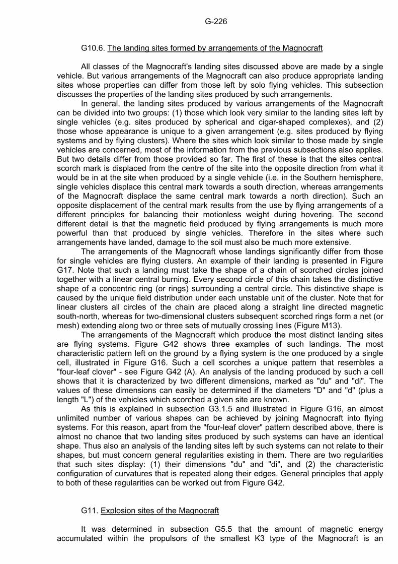
G-226
G10.6. The landing sites formed by arrangements of the Magnocraft All classes of the Magnocraft's landing sites discussed above are made by a single vehicle. But various arrangements of the Magnocraft can also produce appropriate landing sites whose properties can differ from those left by solo flying vehicles. This subsection discusses the properties of the landing sites produced by such arrangements. In general, the landing sites produced by various arrangements of the Magnocraft can be divided into two groups: (1) those which look very similar to the landing sites left by single vehicles (e.g. sites produced by spherical and cigar-shaped complexes), and (2) those whose appearance is unique to a given arrangement (e.g. sites produced by flying systems and by flying clusters). Where the sites which look similar to those made by single vehicles are concerned, most of the information from the previous subsections also applies. But two details differ from those provided so far. The first of these is that the sites central scorch mark is displaced from the centre of the site into the opposite direction from what it would be in at the site when produced by a single vehicle (i.e. in the Southern hemisphere, single vehicles displace this central mark towards a south direction, whereas arrangements of the Magnocraft displace the same central mark towards a north direction). Such an opposite displacement of the central mark results from the use by flying arrangements of a different principles for balancing their motionless weight during hovering. The second different detail is that the magnetic field produced by flying arrangements is much more powerful than that produced by single vehicles. Therefore in the sites where such arrangements have landed, damage to the soil must also be much more extensive. The arrangements of the Magnocraft whose landings significantly differ from those for single vehicles are flying clusters. An example of their landing is presented in Figure G17. Note that such a landing must take the shape of a chain of scorched circles joined together with a linear central burning. Every second circle of this chain takes the distinctive shape of a concentric ring (or rings) surrounding a central circle. This distinctive shape is caused by the unique field distribution under each unstable unit of the cluster. Note that for linear clusters all circles of the chain are placed along a straight line directed magnetic south-north, whereas for two-dimensional clusters subsequent scorched rings form a net (or mesh) extending along two or three sets of mutually crossing lines (Figure M13). The arrangements of the Magnocraft which produce the most distinct landing sites are flying systems. Figure G42 shows three examples of such landings. The most characteristic pattern left on the ground by a flying system is the one produced by a single cell, illustrated in Figure G16. Such a cell scorches a unique pattern that resembles a "four-leaf clover" - see Figure G42 (A). An analysis of the landing produced by such a cell shows that it is characterized by two different dimensions, marked as "du" and "di". The values of these dimensions can easily be determined if the diameters "D" and "d" (plus a length "L") of the vehicles which scorched a given site are known. As this is explained in subsection G3.1.5 and illustrated in Figure G16, an almost unlimited number of various shapes can be achieved by joining Magnocraft into flying systems. For this reason, apart from the "four-leaf clover" pattern described above, there is almost no chance that two landing sites produced by such systems can have an identical shape. Thus also an analysis of the landing sites left by such systems can not relate to their shapes, but must concern general regularities existing in them. There are two regularities that such sites display: (1) their dimensions "du" and "di", and (2) the characteristic configuration of curvatures that is repeated along their edges. General principles that apply to both of these regularities can be worked out from Figure G42. G11. Explosion sites of the Magnocraft It was determined in subsection G5.5 that the amount of magnetic energy accumulated within the propulsors of the smallest K3 type of the Magnocraft is an
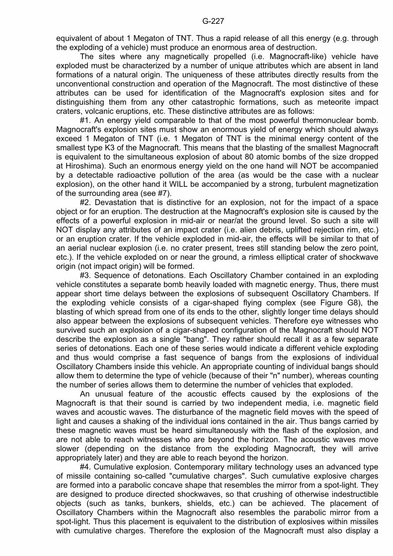
G-227
equivalent of about 1 Megaton of TNT. Thus a rapid release of all this energy (e.g. through the exploding of a vehicle) must produce an enormous area of destruction. The sites where any magnetically propelled (i.e. Magnocraft-like) vehicle have exploded must be characterized by a number of unique attributes which are absent in land formations of a natural origin. The uniqueness of these attributes directly results from the unconventional construction and operation of the Magnocraft. The most distinctive of these attributes can be used for identification of the Magnocraft's explosion sites and for distinguishing them from any other catastrophic formations, such as meteorite impact craters, volcanic eruptions, etc. These distinctive attributes are as follows: #1. An energy yield comparable to that of the most powerful thermonuclear bomb. Magnocraft's explosion sites must show an enormous yield of energy which should always exceed 1 Megaton of TNT (i.e. 1 Megaton of TNT is the minimal energy content of the smallest type K3 of the Magnocraft. This means that the blasting of the smallest Magnocraft is equivalent to the simultaneous explosion of about 80 atomic bombs of the size dropped at Hiroshima). Such an enormous energy yield on the one hand will NOT be accompanied by a detectable radioactive pollution of the area (as would be the case with a nuclear explosion), on the other hand it WILL be accompanied by a strong, turbulent magnetization of the surrounding area (see #7). #2. Devastation that is distinctive for an explosion, not for the impact of a space object or for an eruption. The destruction at the Magnocraft's explosion site is caused by the effects of a powerful explosion in mid-air or near/at the ground level. So such a site will NOT display any attributes of an impact crater (i.e. alien debris, uplifted rejection rim, etc.) or an eruption crater. If the vehicle exploded in mid-air, the effects will be similar to that of an aerial nuclear explosion (i.e. no crater present, trees still standing below the zero point, etc.). If the vehicle exploded on or near the ground, a rimless elliptical crater of shockwave origin (not impact origin) will be formed. #3. Sequence of detonations. Each Oscillatory Chamber contained in an exploding vehicle constitutes a separate bomb heavily loaded with magnetic energy. Thus, there must appear short time delays between the explosions of subsequent Oscillatory Chambers. If the exploding vehicle consists of a cigar-shaped flying complex (see Figure G8), the blasting of which spread from one of its ends to the other, slightly longer time delays should also appear between the explosions of subsequent vehicles. Therefore eye witnesses who survived such an explosion of a cigar-shaped configuration of the Magnocraft should NOT describe the explosion as a single "bang". They rather should recall it as a few separate series of detonations. Each one of these series would indicate a different vehicle exploding and thus would comprise a fast sequence of bangs from the explosions of individual Oscillatory Chambers inside this vehicle. An appropriate counting of individual bangs should allow them to determine the type of vehicle (because of their "n" number), whereas counting the number of series allows them to determine the number of vehicles that exploded. An unusual feature of the acoustic effects caused by the explosions of the Magnocraft is that their sound is carried by two independent media, i.e. magnetic field waves and acoustic waves. The disturbance of the magnetic field moves with the speed of light and causes a shaking of the individual ions contained in the air. Thus bangs carried by these magnetic waves must be heard simultaneously with the flash of the explosion, and are not able to reach witnesses who are beyond the horizon. The acoustic waves move slower (depending on the distance from the exploding Magnocraft, they will arrive appropriately later) and they are able to reach beyond the horizon. #4. Cumulative explosion. Contemporary military technology uses an advanced type of missile containing so-called "cumulative charges". Such cumulative explosive charges are formed into a parabolic concave shape that resembles the mirror from a spot-light. They are designed to produce directed shockwaves, so that crushing of otherwise indestructible objects (such as tanks, bunkers, shields, etc.) can be achieved. The placement of Oscillatory Chambers within the Magnocraft also resembles the parabolic mirror from a spot-light. Thus this placement is equivalent to the distribution of explosives within missiles with cumulative charges. Therefore the explosion of the Magnocraft must also display a
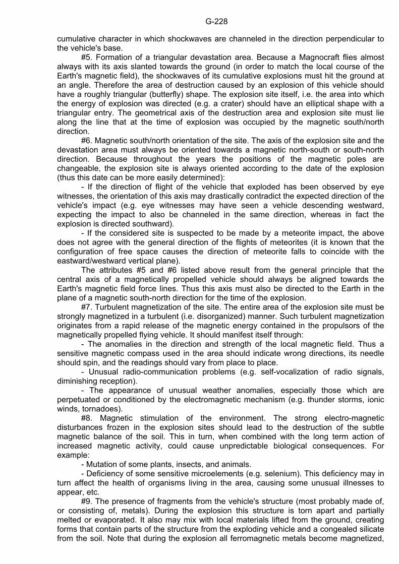
G-228
cumulative character in which shockwaves are channeled in the direction perpendicular to the vehicle's base. #5. Formation of a triangular devastation area. Because a Magnocraft flies almost always with its axis slanted towards the ground (in order to match the local course of the Earth's magnetic field), the shockwaves of its cumulative explosions must hit the ground at an angle. Therefore the area of destruction caused by an explosion of this vehicle should have a roughly triangular (butterfly) shape. The explosion site itself, i.e. the area into which the energy of explosion was directed (e.g. a crater) should have an elliptical shape with a triangular entry. The geometrical axis of the destruction area and explosion site must lie along the line that at the time of explosion was occupied by the magnetic south/north direction. #6. Magnetic south/north orientation of the site. The axis of the explosion site and the devastation area must always be oriented towards a magnetic north-south or south-north direction. Because throughout the years the positions of the magnetic poles are changeable, the explosion site is always oriented according to the date of the explosion (thus this date can be more easily determined): - If the direction of flight of the vehicle that exploded has been observed by eye witnesses, the orientation of this axis may drastically contradict the expected direction of the vehicle's impact (e.g. eye witnesses may have seen a vehicle descending westward, expecting the impact to also be channeled in the same direction, whereas in fact the explosion is directed southward). - If the considered site is suspected to be made by a meteorite impact, the above does not agree with the general direction of the flights of meteorites (it is known that the configuration of free space causes the direction of meteorite falls to coincide with the eastward/westward vertical plane). The attributes #5 and #6 listed above result from the general principle that the central axis of a magnetically propelled vehicle should always be aligned towards the Earth's magnetic field force lines. Thus this axis must also be directed to the Earth in the plane of a magnetic south-north direction for the time of the explosion. #7. Turbulent magnetization of the site. The entire area of the explosion site must be strongly magnetized in a turbulent (i.e. disorganized) manner. Such turbulent magnetization originates from a rapid release of the magnetic energy contained in the propulsors of the magnetically propelled flying vehicle. It should manifest itself through: - The anomalies in the direction and strength of the local magnetic field. Thus a sensitive magnetic compass used in the area should indicate wrong directions, its needle should spin, and the readings should vary from place to place. - Unusual radio-communication problems (e.g. self-vocalization of radio signals, diminishing reception). - The appearance of unusual weather anomalies, especially those which are perpetuated or conditioned by the electromagnetic mechanism (e.g. thunder storms, ionic winds, tornadoes). #8. Magnetic stimulation of the environment. The strong electro-magnetic disturbances frozen in the explosion sites should lead to the destruction of the subtle magnetic balance of the soil. This in turn, when combined with the long term action of increased magnetic activity, could cause unpredictable biological consequences. For example: - Mutation of some plants, insects, and animals. - Deficiency of some sensitive microelements (e.g. selenium). This deficiency may in turn affect the health of organisms living in the area, causing some unusual illnesses to appear, etc. #9. The presence of fragments from the vehicle's structure (most probably made of, or consisting of, metals). During the explosion this structure is torn apart and partially melted or evaporated. It also may mix with local materials lifted from the ground, creating forms that contain parts of the structure from the exploding vehicle and a congealed silicate from the soil. Note that during the explosion all ferromagnetic metals become magnetized,
G-229
therefore iron remains of the vehicle should appear as "magnetite" (i.e. magnetized iron oxide particles). #10. The presence at the site of some minerals originating from the liquidation and subsequent hardening of the site's native soil, lifted (sucked) or rejected as the result of the explosion. These minerals may take either the form of trinitite-type dust falls or china-type (ceramic) stones. The "trinitite" dust falls originate from the sucking of loose soil dust by the explosion, the melting of this dust, and subsequent dropping of it after being hardened. It contains numerous globules of silicate in small, glassy droplets or bulbs, like the congealed particles of "trinitite" found in 1945 at the atomic test site at Alamogordo, New Mexico. The larger ceramic "china stones" are formed from big lumps of clay and soil originating from an explosion site that were blasted into the air, compressed by the pressure of the explosion, aerodynamically shaped by the flight, baked by the heat, and then dropped along the direction of the shockwaves. Thus they take aerodynamic shapes, and their properties resemble those of china. Sometimes china stones may incorporate organic matter (leaves, branches, grass, etc.) that during the explosion mixed with local soil. China stones can be formed only during near ground or ground level (i.e. not mid-air) explosions whose shockwaves spray lumps of soil into the air. #11. Eye witness reports. Local stories describing the explosion should contain some eye witness accounts which indicate that a flying vehicle had been seen just before the actual explosion took place. #12. Interest in the site displayed by pilots of other magnetically propelled vehicles. This interests originates from the three following sources: (a) Operational. The strong magnetization of the explosion site must disturb the environmental magnetic field, thus interacting with the vehicles' propulsion systems. In effect, some reaction on the part of the controlling computers is forced. This in turn must draw the attention of the crews of such vehicles to the site, as a slippery road draws the attention of car drivers. Of course, the scientifically-minded members of the crews should try to check what the cause of these flight disturbances is. (b) Psychological. The place where a magnetically propelled vehicle exploded must fascinate pilots of other similar vehicles. This fascination corresponds to that of car drivers who are drawn to the sites of fatal car accidents. Therefore, just for pure curiosity, pilots of similar vehicles may take the opportunity of flying nearby to have a close look at the place where their colleagues died so spectacularly. (c) Scientific. Because of the cataclysmic consequences of each Magnocraft's explosion, the designers of this vehicle must do everything possible to prevent a recurrence of such a catastrophe. Therefore, there will not be many places where such a vehicle exploded. But if an explosion in fact occurs, its site must be the subject of intensive scientific research to investigate the causes, course, and consequences of such an explosion. Of course, any more noticeable interest in a particular area by pilots of such advanced vehicles as the Magnocraft must be noticed by the local population. Moreover, all landings of these vehicles must leave marks on the ground, which are described in subsection G10. Therefore, reports of local citizens of the frequent sightings of the Magnocraft, supported by the presence of numerous landing marks, will provide further distinctive attributes that should help to identify a Magnocraft's explosion site.
* * * It is worth mentioning at this stage that two sites whose attributes exactly correspond to those listed above have already been discovered and investigated. These are: the Tunguska Blast Site (formed on 30 June 1908 in the Tunguska region of Central Siberia, USSR) and the Tapanui Crater (formed on 19 June 1178 in West Otago, New Zealand). A more detailed description of both these sites is provided in subsection M3. G12. Summary of the attributes of the Magnocraft
G-230
This subsection summarizes all the attributes of the Magnocraft that have been discussed or revealed in previous parts of this chapter. A review of them makes us realize how a powerful vehicle the Magnocraft is and what type of phenomena its observers and users may encounter. For the consistency of the review, various attributes are grouped in classes depending on their mutual relationship (not on the order of their presentation in previous subsections). These classes are numbered from #1 to #12. #1. The unique, disc-like shape similar to that of an inverted saucer. The characteristic attributes of this shape are: (a) Its flattening ratio "K=D/H", expressed by the design factor called "Krotnosc", is a mathematical function of the number "n" of side propulsors (see equation G6) and takes the integer value from the range K=3 to K=10. (b) It forms the eight basic types of the Magnocraft which can be recognized from this shape, or from the value of their design factor "K", diameters "D" and "d", or the number of propulsors "n". (c) It repeats the same main elements in the shells of all types of the Magnocraft, although the shape and mutual configurations of these elements may differ slightly in various types. (d) It is strictly defined by the set of equations listed in Figure G23. #2. An ability to couple a number of Magnocraft into various flying arrangements which appear as essentially different shapes. The manifestation of this ability is that: (a) Apart from the saucer-like shape of a single unit, the flying Magnocraft can also be observed taking almost any shape that can be imagined, e.g. sphere, cigar, cone, fir-tree, beads, spool, four-leaf clover, honeycomb, platform, cross. (b) The Magnocraft is able to form six different classes of flying arrangements. These are: (1) flying complexes, (2) semi-attached configurations, (3) detached configurations, (4) carrier platforms, (5) flying systems, and (6) flying clusters (see Figure G6). (c) Arrangements of a number of Magnocraft are able to couple and decouple during flight. (d) The gelatinous hydraulic substance which fills the space between two vehicles (angel's hair) drops to the Earth's surface at the moment of the disconnection of a spherical flying complex or a double-ended cigar-shaped complex. #3. The lack of parts cooperating mechanically which could become worn out with wear and tear. The reasons for this are: (a) The principles of the Magnocraft's operation do not require any moving parts. (b) The moving parts that are introduced for the convenience of the crew are designed in a manner in which mechanical cooperation is unnecessary (see the free-floating suspension of the Oscillatory Chambers within the propulsors - subsection G1.1). The effects gained by this are: (A) An almost unlimited time for use of the vehicle. (B) An extremely low potential for failure. (C) A low cost of production. #4. The propulsion unit of the Magnocraft is constituted as the balanced arrangement of two different types of propulsors producing counter-acting forces, the first of which supports the vehicle while the other stabilizes it. The important points associated with such a formation of the propulsion are: (a) The configuration of propulsors that form a bell-shape (i.e. where one propulsor is uplifted at the center of the vehicle, and the others positioned around it but slightly below the central propulsor). (b) The formation of magnetic circuits. (c) An unique layout of the burnt marks left at landing sites that correspond to the location of the propulsors. (d) The existence of the "magnetic framework" which strengthens the resistance of the vehicle's shell.
G-231
(e) The controllability over the magnetic interactions with other vehicles. These interactions can be changed smoothly from attraction into repulsion. #5. The utilization of magnetic interactions with the environmental field for producing propelling forces. This provides: (a) Noiselessness in flight. (b) The achievement of speeds in a vacuum close to the speed of light. (c) The ability to produce propelling forces in all environments. (d) Magnetic changes forced on surrounding areas, such as: (1) burn marks on plants and on the ground; (2) properties of the soil changed by the magnetic action; (3) disturbance of the Earth's magnetic field; (4) neutralization of the natural magnetism of materials; (5) erasure of tape recordings and the recording on them of a pulsating signal. (e) Magnetic forces acting on metal objects. Such forces may cause: (1) the momentary joining together of adjacent parts of machines (which in turn causes engines to stop working, turbines to stop rotating, etc.); (2) the pushing or pulling (depending on the wishes of the crew - see Figure F8) of complete objects from the pulsating magnetic field generated by the Magnocraft; (3) the humming of metallic objects (when they are supported by any flexible material). (f) The physical effects on living organisms. These may appear as: (1) an unusual impression of a humming sound sensed by a person under the influence of the field but which in reality does not exist; (2) a metallic taste in the mouth that doesn't have any connection with what has been eaten; (3) a special kind of paralysis that numbs the mind and actions of a person in the range of the Magnocraft's field. #6. The ability to create a magnetic whirl. Its effects can be: (a) A whirl of air or water which follows the whirling magnetic field (this whirl breaks a sound wave produced by the vehicle). (b) The creation of a local vacuum bubble near the surface of the craft, which makes possible the noiseless flight of the Magnocraft in air or water, with speeds much higher that those possible with the heat barrier. (c) A flattening of plants in swaths around the Magnocraft's landing sites. (d) Creation of the magnetic equivalent of the "Magnus Effect" which produces a thrust force acting in the latitudinal direction. (e) The formation of an inductive shield around the vehicle, which is able to destroy any objects made of good electric conductors in its path. The effects of using such a shield can include: (1) all objects that are made of metal explode when they come in contact with the Magnocraft; (2) splinters from the exploding objects are porous and have an uneven surface; (3) the temperature of all metallic objects entering the range of the shield rapidly increases. (f) The formation of tunnels and craters of geometric shapes in solid objects and in the Earth's crust. #7. The ability to operate in three different modes called: the magnetic whirl mode, the throbbing mode, and the magnetic lens mode. The manifestation of the use of these modes is: (a) The appearance to eye-witnesses on one occasion as material vehicles with clearly distinguishable surfaces, and on another as clouds of ionized air. From both of the above modes they can also be re-controlled into a magnetic lens mode, thus disappearing completely from view. (b) The displaying of opposite and reciprocally negating properties, for example: - in the magnetic whirl mode: (1) the burning, destroying and falling down of everything within the vicinity of the Magnocraft; (2) induction of an electrical "cork" which cuts off the flow of current in electric power mains. - in the throbbing mode: (1) safe and nondestructive work of the propulsors; (2) generation of the flow of current in electrical devices which are disconnected from sources of energy. #8. The induction of electric currents. The effects of these currents produce the following phenomena:
G-232
(a) The electrical charging of non-conductive materials (e.g. hair, clothing, plants). (b) Causing the operation of appliances that have been disconnected from their source of electricity (e.g. radio and television receivers, vacuum cleaners, etc.). (c) Ionization of the surrounding medium and the production of highly active ozone. When the Magnocraft is flying in the air, this causes: (1) a smell of ozone near the Magnocraft itself and on its path of flight; (2) the formation of chemical components (salts) from the close contact of materials and the ionized air - these salts are produced because of the reaction of environmental substances (soil, air, pollution, etc.) with very active ozone; (3) emission of radiation, caused by the bombardment of hard materials with high energy ions; (4) condensation of steam in the wake of the flying Magnocraft. #9. The emission of various light signals. The sources of these signals, resulting from the vehicle's operation (i.e. "natural" sources of light) are: (a) In the magnetic whirl mode of operation: the ionic picture of the whirl. The light from the whirl displays approximately the same colour and the same intensity in the whole volume. The luminous flux produced is very high. (b) In the throbbing mode of operation: a glowing of the surrounding medium in two "opposite" colours at the propulsor outlets (i.e. in the air, a yellow-red near the north (N) pole and a blue-green near the south (S) magnetic pole of each propulsor). Characteristic for this glow are: (1) the "opposite" colours of the light are emitted from the main and side propulsors' outlets situated on the same side (on topside or underside) of the vehicle; (2) the colours that the same propulsors glow are reversed when viewed from below and above the vehicle; (3) the change of colours into "opposite" ones after the Magnocraft flies over one of the Earth's magnetic poles (this change is caused by the need to reorientate the propulsors). (c) In the magnetic lens mode: a very sensitive photographic film should be able to detect a light from the crew cabin (if any is produced) passing through the lens from inwards. The naked eye or radar is not able to detect the presence of the vehicle. The sources of the "artificial" light signals emitted by the Magnocraft are: (d) The SUB system performing the function of navigation lamps. (e) The propulsors used by the crew as searchlights for lighting a chosen area under the vehicle. #10. Interference with the paths of electromagnetic radiation. This interference may take one of the following forms: (a) A "magnetic lens" which deflects electromagnetic radiation from the vehicle, making it totally invisible to visual watch and radar detection. The lens is obtained when the Magnocraft's field is constant and forms the shape of the lens whose boundaries display a smooth change in the field's density. A partial lens can also appear when the vehicle's field is pulsating. Such a partial magnetic lens may obstruct or deform the visibility of the shell near the outlets from the Magnocraft's propulsors. (b) An enhancement of the sighting of the main twin-chamber capsule in an ascending Magnocraft, connected with the simultaneous diminishing of the whole body of the vehicle. (c) "Black bars" joining the outlets of the facing propulsors in some arrangements of coupled Magnocraft (e.g. semi-attached and detached configurations, cigar-shaped complexes, etc.) and black areas visible inside the twin-chamber capsules. These bars and areas are obtained when the columns of a highly concentrated magnetic field with clearly distinguishable boundaries (e.g. produced between facing propulsors of the coupled vehicles) are observed from the direction perpendicular to the magnetic field force lines. (d) Disturbances in radio reception, television broadcasts, radar images, and telephone signals. These are induced when the Magnocraft's whirling magnetic field emits its own electromagnetic waves. #11. Fully controllable, and reversible, energy management. It is manifested in the following ways: (a) The character and parameters of the vehicle's field are formed exactly as are necessary for the flight conditions.
G-233
(b) The produced field can be reduced without any change in the amount of energy accumulated in the propulsors. (c) The Magnocraft can hover motionless near the ground like a balloon for any period of time without decreasing the amount of its energy. (d) The vehicle's magnetic field accumulates (before flight) the entire energy necessary for a long-distance trip. (e) The vehicle's energy resources are self-rechargeable. If the flight does not involve friction, the energy resources at the moment of finishing a round trip are the same as at the moment of starting this trip. #12. The magnetic (non-aerodynamic) manner of flying which adheres to the laws of magnetism. This is characterized by: (a) Flights with the base almost perpendicular to the force lines of the environmental magnetic field. This means that the Magnocraft always maintains the same orientation (i.e. its base faces roughly a north-south direction), independently of the direction of its movement and the type of maneuver it is performing. Moreover, the Magnocraft moves in directions that are independent from its orientation, even if these directions produce the highest aerodynamic resistance of its shell. (b) Flying along straight lines, with rapid changes of direction without the benefit of a curve radius. (c) Rapid jumps into random directions mixed with frequent stops, which to observers resemble the behaviour of a "dragon fly". (d) The ability to hover motionlessly in one place for extensively long periods of time (e.g. hours, days, or even longer). G13. Military aspects of the Magnocraft It must be emphasized that building a Magnocraft will promote peace through providing the facilities for interstellar expansion and for the utilization of unlimited cosmic resources. However, in our highly militarized world it is impossible to create a new kind of vehicle which potentially would not be used for military purposes. Therefore, to complete the picture of this vehicle, its basic military capabilities must also be highlighted. This is because today's predictions of the Theory of the Magnocraft may in the not-too-distant future become a surprising reality for those citizens of our planet whose taxes maintain scholars preoccupied with condemning subjects which in their opinion are unbecoming to scientists, to still have time for observing what is happening around them. The most simple military application of the Magnocraft is a rapid releasing (for example through a detonation) of the huge amount of energy accumulated in its propulsors. The explosion caused in this way in its effects and range could be compared only to the famous Tunguska (USSR) blast, which on 30 June 1908 devastated over a thousand square kilometres of taiga in the Tunguska region of Central Siberia. As was the case with this event, the exploding of the Magnocraft would not pollute the environment radioactively. Therefore the affected area would immediately be available for occupation and colonization. However, using the Magnocraft as a flying bomb would be a waste of its huge military potential. The other possible applications of this vehicle offer even greater advantages. It can act as a transportation facility carrying weapons and military forces for attacking the command centers and government locations of the opposite side, or as a very selectively acting weapon for controlled destruction. This subsection reviews the capabilities of the Magnocraft in both of these applications. G13.1. Use of the Magnocraft as a weapons platform or transportation facility In the transportation or weapons platform mode, the following characteristics of the Magnocraft can be significant:
G-234
1. Very high speeds. In excess of 70,000 km per hour in the atmosphere and almost at the speed of light when travelling in the near vacuum of space. 2. The capability to move through any medium, i.e. space, air, water, solid materials (such as soil, rocks, buildings, or bunkers) and also molten media such as the Earth's nuclei or the centres of stars. It can also move from one medium to another with no preparation necessary. 3. The capability to move directly to the target despite any man-made or natural obstacles in its path. The Magnocraft can tunnel through the Earth's surface, buildings, pillboxes, barriers and anything else that can be used for the protection of command centers and underground bunkers. 4. The Magnocraft, when flying, is completely noiseless and has the capability to switch on optical and radar invisibility. 5. Special characteristics enabling a Magnocraft to withstand any weapon that could be used against it. The features which protect the vehicle against weapons are: (a) A spinning magnetic field that creates an "inductive shield", a destructive "plasma saw" made from ionized air molecules that follow the spinning magnetic force lines, and the repelling action of a pulsating magnetic field (see Figure F8). These effects act on missiles, guns, and other projectile (non-energy) weapons. (b) A "magnetic framework" formed within the vehicle which provides support many times stronger than any physical body can. This framework is able to withstand the shockwaves of nearby explosions. (c) A "magnetic lens" which deflects laser beams and other energy-beam weapons as well as the thermal radiation from a nuclear explosion. 6. An effective resistance to extreme environmental conditions: (a) Very high temperatures. Heat transfer is made impossible because the environmental medium is kept away from the Magnocraft's surface by the plasma whirl which uses the centrifugal force to reject all alien particles. (b) Very high pressures. These are neutralized by the "magnetic framework" which can withstand any possible external pressure. (c) High energy electromagnetic radiation. This is deflected by the "magnetic lens" which is produced by the constant output from the Magnocraft's propulsors. 7. The ability to switch on a "field of attraction" which would intercept and neutralize any nearby objects that are constructed of ferromagnetic materials. This applies to cars, large guns, tanks, and even aeroplanes. The attraction force is created by the constant component of the magnetic field yield from the vehicle's propulsors - see Figure F8. Its range and attraction effect can be controlled by balancing with the repulsion force which is produced by the pulsating component of the vehicle's magnetic field. G13.2. Use of the Magnocraft as a selectively acting weapon To use the Magnocraft as a selectively acting weapon for controlled destruction, concentrating its impact on the metallic objects of the other side, the destructive properties of its "inductive shield" are utilized. Simultaneously the "plasma whirl", always appearing together with the inductive shield, is prevented from acting on people and on organic substances so that they stay uninjured. The method by which the Magnocraft can be used for military operations, aimed at the destruction of the enemy's equipment only, is as follows: Step 1. Switching to maximum power the spinning magnetic field that forms the magnetic whirl circulating around the vehicle. The force lines of that field passing through nearby conductive objects induce in them powerful electric currents that explosively evaporate their material. Step 2. Forming from this spinning field a broad inductive shield with a range of evaporation to about 100 metres from the vehicle's surface (when the destructive plasma whirl has a range of only about 5 metres).
G-235
Step 3. Flying at an altitude of around 10 to 30 metres above an enemy's territory. As a result of such a flight, every object which is constructed from electrically conducting material will explode. This effect has a radius of about 100 metres from the craft. The disintegration of these materials will cause in turn: (a) Complete destruction of every object made of metal, such as: weapons, machinery, factories and their equipment, iron bridges, electric-power connections, underground installations made of metal, storage facilities, etc. (b) Destruction or damage of objects containing some parts made of metal, such as: buildings, concrete bridges, bunkers, roads, airfields, ports, etc. Step 4. Undertaking a systematic flight covering every part of the target area, similar to the way a farmer ploughs a field. It should be noted that the very high speed and manoeuvrability of the Magnocraft would allow operation in such a manner as to render totally powerless a middle-sized European country, with only one Magnocraft, in about 12 hours. The military properties of the Magnocraft used as a weapon have no equivalent in any other fighting facility made by man to date. There are neither weapons nor defense methods that can oppose this vehicle. However, there is a major difference between the action of the Magnocraft and the effects of other means of mass destruction. The Magnocraft acts selectively against the weapons, equipment, and technology of the other side, but not against people. So it disarms the enemy but leaves the population alive. Therefore even when used as a tool of destruction, it can still promote peace and serve humanity.
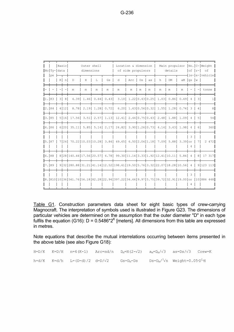
G-236
Basic Outer shell Location & dimension Main propulsor No.C-Weight
NoTy-data dimensions of side propulsors details of r- of
pe le-e-vehicle
K n D H L Gs d Arc Ds as h DM aM gs w
- - - - m m m m m m m m m m m - - tonne
1.K3 3 8 4.39 1.46 0.64 0.43 3.10 1.220.430.25 1.03 0.86 0.49 4 3 1
2.K4 412 8.78 2.19 1.28 0.72 6.20 1.630.560.32 1.55 1.28 0.74 3 4 8
3.K5 516 17.56 3.51 2.57 1.13 12.41 2.440.750.43 2.48 1.88 1.09 4 5 54
4.K6 620 35.11 5.85 5.14 2.17 24.82 3.901.260.73 4.14 3.43 1.98 4 6 360
3
5.K7 724 70.2210.0310.28 3.84 49.65 6.502.041.18 7.09 5.88 3.39or 7 2 472
4
6.K8 828140.4417.5620.57 6.78 99.3011.143.331.9212.4110.11 5.84 4 8 17 317
7.K9 932280.8831.2141.1412.52198.6119.505.763.3222.0718.2810.56 4 9123 113
3
8.K101036561.7656.1882.2822.94397.2234.669.975.7539.7232.9119.00or 10886 448
4
Table G1. Construction parameters data sheet for eight basic types of crew-carrying Magnocraft. The interpretation of symbols used is illustrated in Figure G23. The dimensions of particular vehicles are determined on the assumption that the outer diameter "D" in each type fulfils the equation (G16): D = 0.5486*2K [meters]. All dimensions from this table are expressed in metres. Note equations that describe the mutual interrelations occurring between items presented in the above table (see also Figure G18):
H=D/K K=D/H n=4(K-1) Arc=πd/n DM=H(2-%2) aM=DM/%3 as=Ds/%3 Crew=K h=d/K K=d/h L=(D-d)/2 d=D/%2 Gs=DM-Ds Ds=DM/3%n Weight=0.05@D2@H
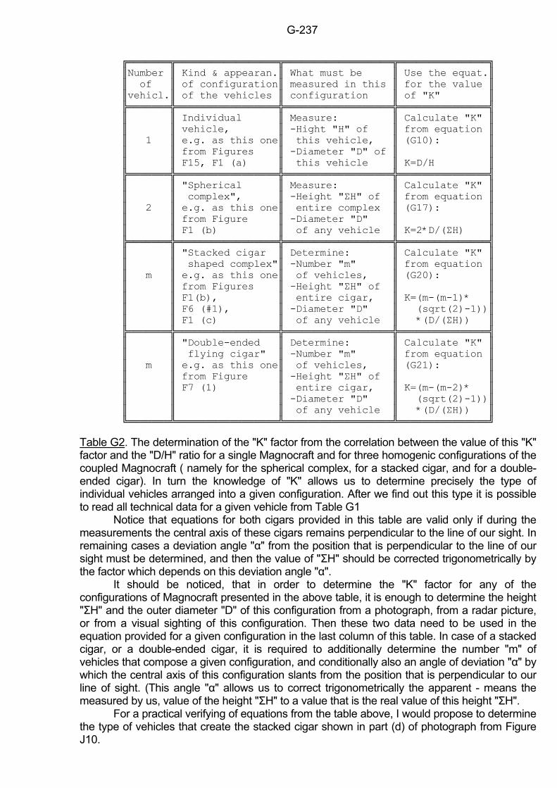
G-237
Number Kind & appearan. What must be Use the equat. of of configuration measured in this for the value vehicl. of the vehicles configuration of "K" Individual Measure: Calculate "K" vehicle, -Hight "H" of from equation 1 e.g. as this one this vehicle, (G10): from Figures -Diameter "D" of F15, F1 (a) this vehicle K=D/H "Spherical Measure: Calculate "K" complex", -Height "ΣH" of from equation 2 e.g. as this one entire complex (G17): from Figure -Diameter "D" F1 (b) of any vehicle K=2*D/(ΣH) "Stacked cigar Determine: Calculate "K" shaped complex" -Number "m" from equation m e.g. as this one of vehicles, (G20): from Figures -Height "ΣH" of F1(b), entire cigar, K=(m-(m-1)* F6 (#1), -Diameter "D" (sqrt(2)-1)) F1 (c) of any vehicle *(D/(ΣH)) "Double-ended Determine: Calculate "K" flying cigar" -Number "m" from equation m e.g. as this one of vehicles, (G21): from Figure -Height "ΣH" of F7 (1) entire cigar, K=(m-(m-2)* -Diameter "D" (sqrt(2)-1)) of any vehicle *(D/(ΣH))
Table G2. The determination of the "K" factor from the correlation between the value of this "K" factor and the "D/H" ratio for a single Magnocraft and for three homogenic configurations of the coupled Magnocraft ( namely for the spherical complex, for a stacked cigar, and for a double-ended cigar). In turn the knowledge of "K" allows us to determine precisely the type of individual vehicles arranged into a given configuration. After we find out this type it is possible to read all technical data for a given vehicle from Table G1 Notice that equations for both cigars provided in this table are valid only if during the measurements the central axis of these cigars remains perpendicular to the line of our sight. In remaining cases a deviation angle "α" from the position that is perpendicular to the line of our sight must be determined, and then the value of "ΣH" should be corrected trigonometrically by the factor which depends on this deviation angle "α". It should be noticed, that in order to determine the "K" factor for any of the configurations of Magnocraft presented in the above table, it is enough to determine the height "ΣH" and the outer diameter "D" of this configuration from a photograph, from a radar picture, or from a visual sighting of this configuration. Then these two data need to be used in the equation provided for a given configuration in the last column of this table. In case of a stacked cigar, or a double-ended cigar, it is required to additionally determine the number "m" of vehicles that compose a given configuration, and conditionally also an angle of deviation "α" by which the central axis of this configuration slants from the position that is perpendicular to our line of sight. (This angle "α" allows us to correct trigonometrically the apparent - means the measured by us, value of the height "ΣH" to a value that is the real value of this height "ΣH". For a practical verifying of equations from the table above, I would propose to determine the type of vehicles that create the stacked cigar shown in part (d) of photograph from Figure J10.
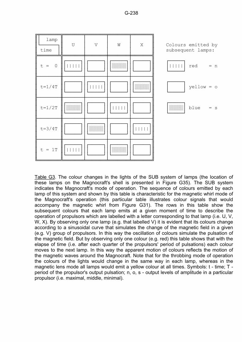
G-238
lamp U V W X Colours emitted by time subsequent lamps: t = 0 ||||| ||||| red = n t=1/4T ||||| yellow = o t=1/2T ||||| blue = s t=3/4T ||||| t = 1T ||||| Table G3. The colour changes in the lights of the SUB system of lamps (the location of these lamps on the Magnocraft's shell is presented in Figure G35). The SUB system indicates the Magnocraft's mode of operation. The sequence of colours emitted by each lamp of this system and shown by this table is characteristic for the magnetic whirl mode of the Magnocraft's operation (this particular table illustrates colour signals that would accompany the magnetic whirl from Figure G31). The rows in this table show the subsequent colours that each lamp emits at a given moment of time to describe the operation of propulsors which are labelled with a letter corresponding to that lamp (i.e. U, V, W, X). By observing only one lamp (e.g. that labelled V) it is evident that its colours change according to a sinusoidal curve that simulates the change of the magnetic field in a given (e.g. V) group of propulsors. In this way the oscillation of colours simulate the pulsation of the magnetic field. But by observing only one colour (e.g. red) this table shows that with the elapse of time (i.e. after each quarter of the propulsors' period of pulsations) each colour moves to the next lamp. In this way the apparent motion of colours reflects the motion of the magnetic waves around the Magnocraft. Note that for the throbbing mode of operation the colours of the lights would change in the same way in each lamp, whereas in the magnetic lens mode all lamps would emit a yellow colour at all times. Symbols: t - time; T - period of the propulsor's output pulsation; n, o, s - output levels of amplitude in a particular propulsor (i.e. maximal, middle, minimal).
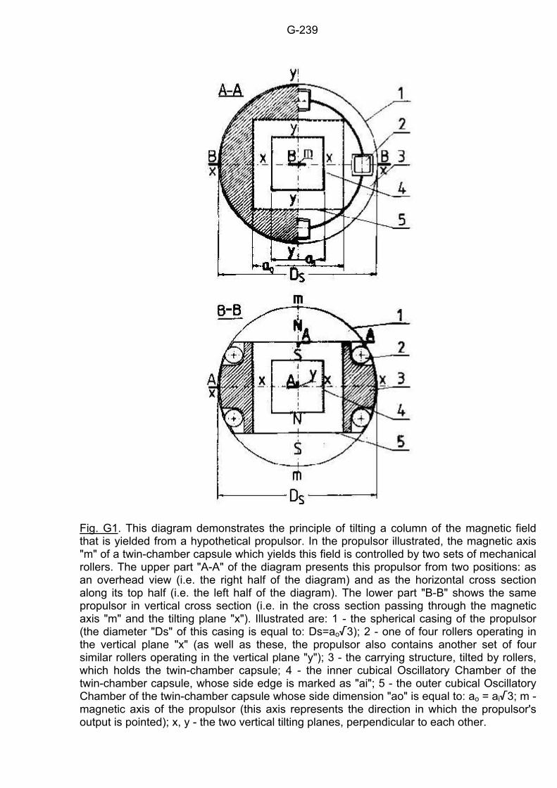
G-239
Fig. G1. This diagram demonstrates the principle of tilting a column of the magnetic field that is yielded from a hypothetical propulsor. In the propulsor illustrated, the magnetic axis "m" of a twin-chamber capsule which yields this field is controlled by two sets of mechanical rollers. The upper part "A-A" of the diagram presents this propulsor from two positions: as an overhead view (i.e. the right half of the diagram) and as the horizontal cross section along its top half (i.e. the left half of the diagram). The lower part "B-B" shows the same propulsor in vertical cross section (i.e. in the cross section passing through the magnetic axis "m" and the tilting plane "x"). Illustrated are: 1 - the spherical casing of the propulsor (the diameter "Ds" of this casing is equal to: Ds=ao/3); 2 - one of four rollers operating in the vertical plane "x" (as well as these, the propulsor also contains another set of four similar rollers operating in the vertical plane "y"); 3 - the carrying structure, tilted by rollers, which holds the twin-chamber capsule; 4 - the inner cubical Oscillatory Chamber of the twin-chamber capsule, whose side edge is marked as "ai"; 5 - the outer cubical Oscillatory Chamber of the twin-chamber capsule whose side dimension "ao" is equal to: ao = ai/3; m - magnetic axis of the propulsor (this axis represents the direction in which the propulsor's output is pointed); x, y - the two vertical tilting planes, perpendicular to each other.
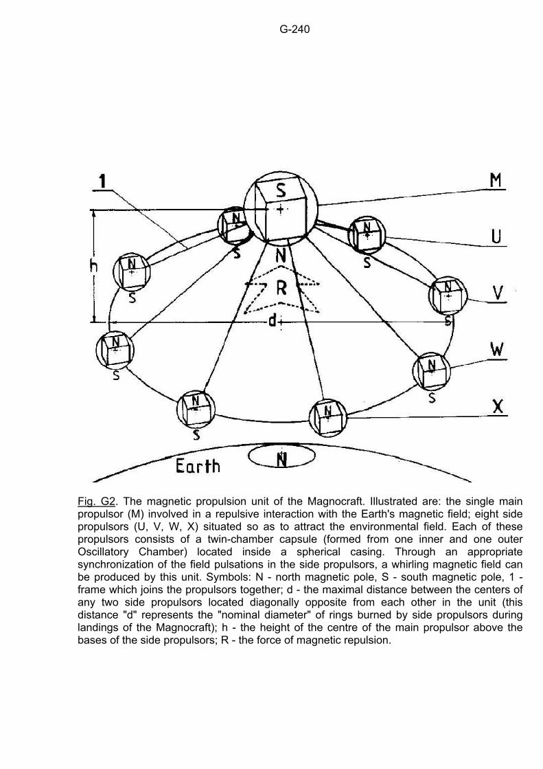
G-240
Fig. G2. The magnetic propulsion unit of the Magnocraft. Illustrated are: the single main propulsor (M) involved in a repulsive interaction with the Earth's magnetic field; eight side propulsors (U, V, W, X) situated so as to attract the environmental field. Each of these propulsors consists of a twin-chamber capsule (formed from one inner and one outer Oscillatory Chamber) located inside a spherical casing. Through an appropriate synchronization of the field pulsations in the side propulsors, a whirling magnetic field can be produced by this unit. Symbols: N - north magnetic pole, S - south magnetic pole, 1 - frame which joins the propulsors together; d - the maximal distance between the centers of any two side propulsors located diagonally opposite from each other in the unit (this distance "d" represents the "nominal diameter" of rings burned by side propulsors during landings of the Magnocraft); h - the height of the centre of the main propulsor above the bases of the side propulsors; R - the force of magnetic repulsion.
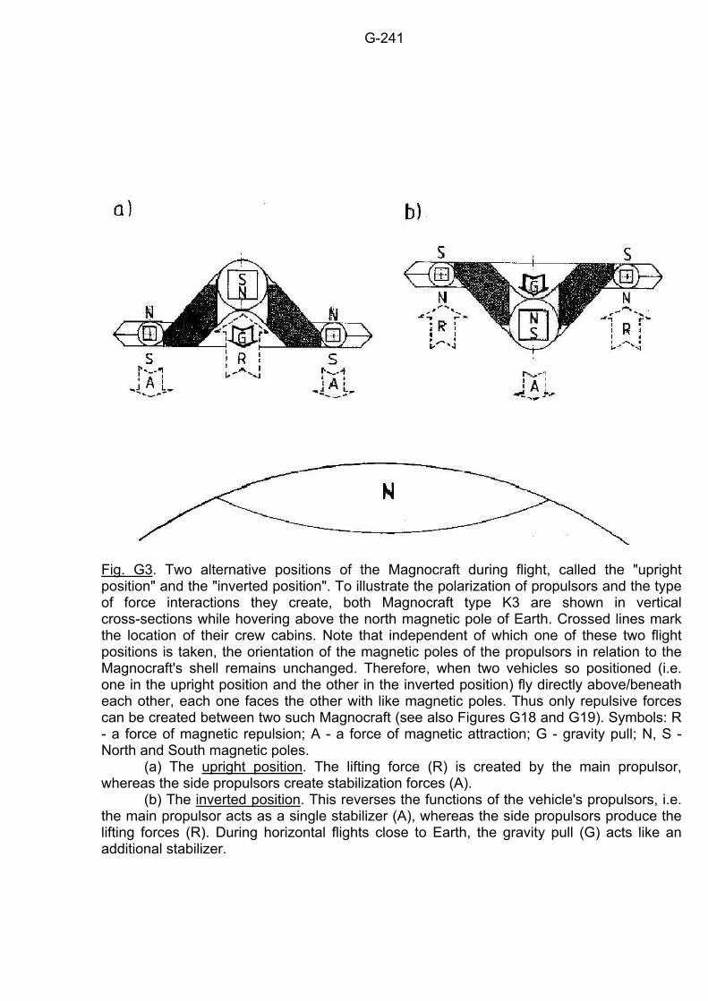
G-241
Fig. G3. Two alternative positions of the Magnocraft during flight, called the "upright position" and the "inverted position". To illustrate the polarization of propulsors and the type of force interactions they create, both Magnocraft type K3 are shown in vertical cross-sections while hovering above the north magnetic pole of Earth. Crossed lines mark the location of their crew cabins. Note that independent of which one of these two flight positions is taken, the orientation of the magnetic poles of the propulsors in relation to the Magnocraft's shell remains unchanged. Therefore, when two vehicles so positioned (i.e. one in the upright position and the other in the inverted position) fly directly above/beneath each other, each one faces the other with like magnetic poles. Thus only repulsive forces can be created between two such Magnocraft (see also Figures G18 and G19). Symbols: R - a force of magnetic repulsion; A - a force of magnetic attraction; G - gravity pull; N, S - North and South magnetic poles. (a) The upright position. The lifting force (R) is created by the main propulsor, whereas the side propulsors create stabilization forces (A). (b) The inverted position. This reverses the functions of the vehicle's propulsors, i.e. the main propulsor acts as a single stabilizer (A), whereas the side propulsors produce the lifting forces (R). During horizontal flights close to Earth, the gravity pull (G) acts like an additional stabilizer.
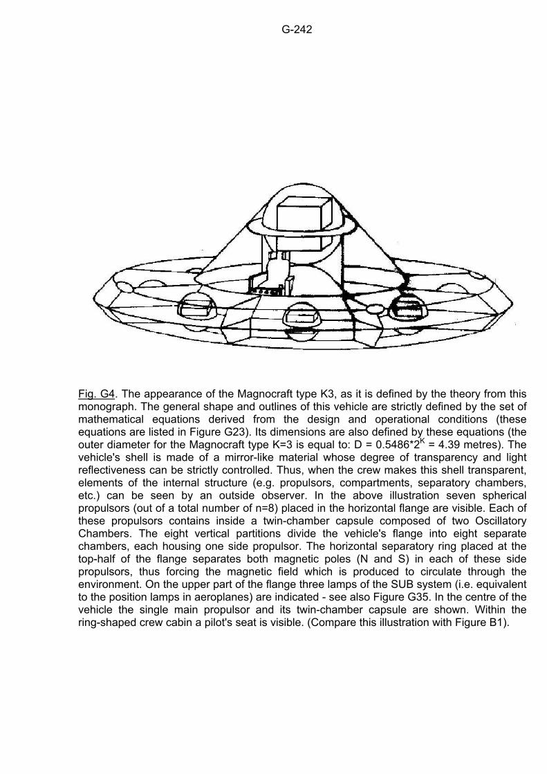
G-242
Fig. G4. The appearance of the Magnocraft type K3, as it is defined by the theory from this monograph. The general shape and outlines of this vehicle are strictly defined by the set of mathematical equations derived from the design and operational conditions (these equations are listed in Figure G23). Its dimensions are also defined by these equations (the outer diameter for the Magnocraft type K=3 is equal to: D = 0.5486*2K = 4.39 metres). The vehicle's shell is made of a mirror-like material whose degree of transparency and light reflectiveness can be strictly controlled. Thus, when the crew makes this shell transparent, elements of the internal structure (e.g. propulsors, compartments, separatory chambers, etc.) can be seen by an outside observer. In the above illustration seven spherical propulsors (out of a total number of n=8) placed in the horizontal flange are visible. Each of these propulsors contains inside a twin-chamber capsule composed of two Oscillatory Chambers. The eight vertical partitions divide the vehicle's flange into eight separate chambers, each housing one side propulsor. The horizontal separatory ring placed at the top-half of the flange separates both magnetic poles (N and S) in each of these side propulsors, thus forcing the magnetic field which is produced to circulate through the environment. On the upper part of the flange three lamps of the SUB system (i.e. equivalent to the position lamps in aeroplanes) are indicated - see also Figure G35. In the centre of the vehicle the single main propulsor and its twin-chamber capsule are shown. Within the ring-shaped crew cabin a pilot's seat is visible. (Compare this illustration with Figure B1).
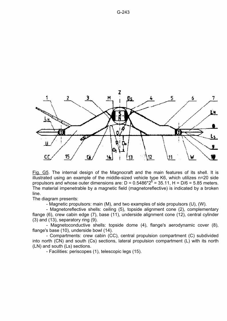
G-243
Fig. G5. The internal design of the Magnocraft and the main features of its shell. It is illustrated using an example of the middle-sized vehicle type K6, which utilizes n=20 side propulsors and whose outer dimensions are: D = 0.5486*26 = 35.11, H = D/6 = 5.85 meters. The material impenetrable by a magnetic field (magnetoreflective) is indicated by a broken line. The diagram presents: - Magnetic propulsors: main (M), and two examples of side propulsors (U), (W). - Magnetoreflective shells: ceiling (5), topside alignment cone (2), complementary flange (6), crew cabin edge (7), base (11), underside alignment cone (12), central cylinder (3) and (13), separatory ring (9). - Magnetoconductive shells: topside dome (4), flange's aerodynamic cover (8), flange's base (10), underside bowl (14). - Compartments: crew cabin (CC), central propulsion compartment (C) subdivided into north (CN) and south (Cs) sections, lateral propulsion compartment (L) with its north (LN) and south (Ls) sections. - Facilities: periscopes (1), telescopic legs (15).
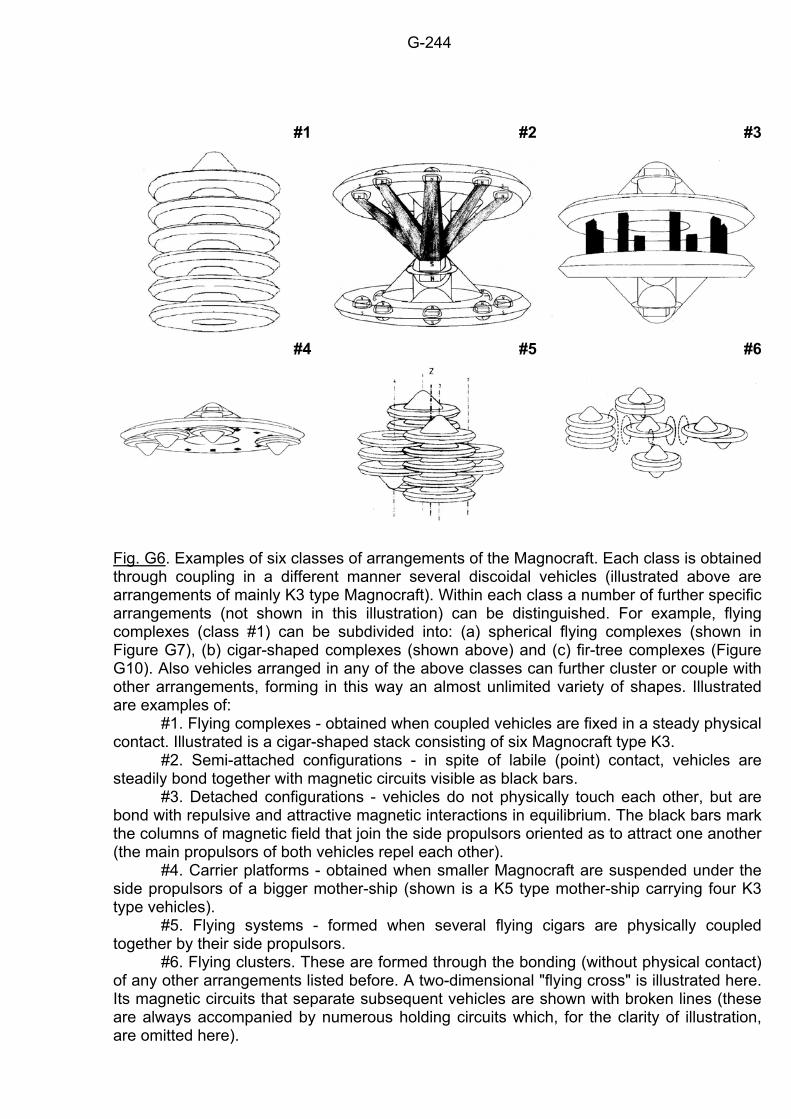
G-244
#1
#2 #3
#4
#5
#6
Fig. G6. Examples of six classes of arrangements of the Magnocraft. Each class is obtained through coupling in a different manner several discoidal vehicles (illustrated above are arrangements of mainly K3 type Magnocraft). Within each class a number of further specific arrangements (not shown in this illustration) can be distinguished. For example, flying complexes (class #1) can be subdivided into: (a) spherical flying complexes (shown in Figure G7), (b) cigar-shaped complexes (shown above) and (c) fir-tree complexes (Figure G10). Also vehicles arranged in any of the above classes can further cluster or couple with other arrangements, forming in this way an almost unlimited variety of shapes. Illustrated are examples of: #1. Flying complexes - obtained when coupled vehicles are fixed in a steady physical contact. Illustrated is a cigar-shaped stack consisting of six Magnocraft type K3. #2. Semi-attached configurations - in spite of labile (point) contact, vehicles are steadily bond together with magnetic circuits visible as black bars. #3. Detached configurations - vehicles do not physically touch each other, but are bond with repulsive and attractive magnetic interactions in equilibrium. The black bars mark the columns of magnetic field that join the side propulsors oriented as to attract one another (the main propulsors of both vehicles repel each other). #4. Carrier platforms - obtained when smaller Magnocraft are suspended under the side propulsors of a bigger mother-ship (shown is a K5 type mother-ship carrying four K3 type vehicles). #5. Flying systems - formed when several flying cigars are physically coupled together by their side propulsors. #6. Flying clusters. These are formed through the bonding (without physical contact) of any other arrangements listed before. A two-dimensional "flying cross" is illustrated here. Its magnetic circuits that separate subsequent vehicles are shown with broken lines (these are always accompanied by numerous holding circuits which, for the clarity of illustration, are omitted here).
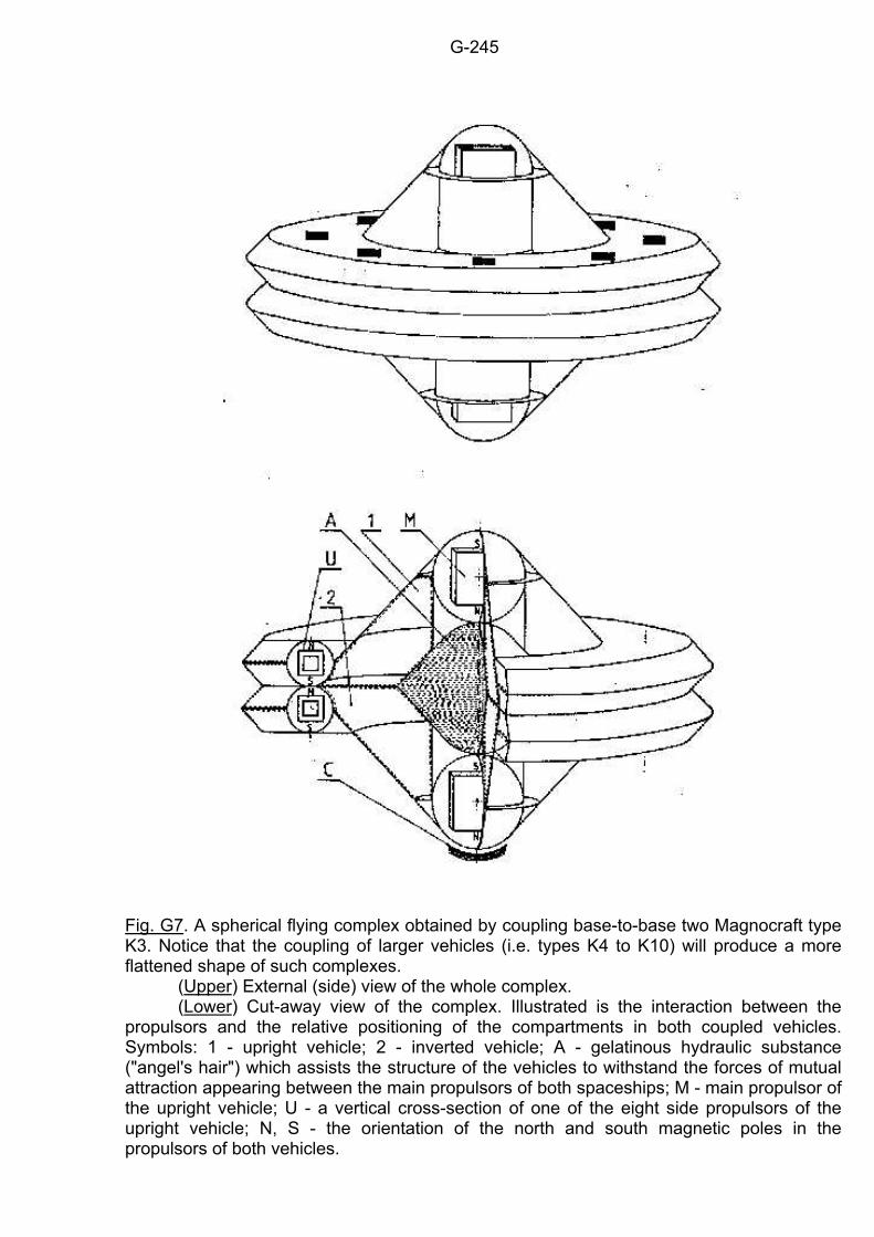
G-245
Fig. G7. A spherical flying complex obtained by coupling base-to-base two Magnocraft type K3. Notice that the coupling of larger vehicles (i.e. types K4 to K10) will produce a more flattened shape of such complexes. (Upper) External (side) view of the whole complex. (Lower) Cut-away view of the complex. Illustrated is the interaction between the propulsors and the relative positioning of the compartments in both coupled vehicles. Symbols: 1 - upright vehicle; 2 - inverted vehicle; A - gelatinous hydraulic substance ("angel's hair") which assists the structure of the vehicles to withstand the forces of mutual attraction appearing between the main propulsors of both spaceships; M - main propulsor of the upright vehicle; U - a vertical cross-section of one of the eight side propulsors of the upright vehicle; N, S - the orientation of the north and south magnetic poles in the propulsors of both vehicles.
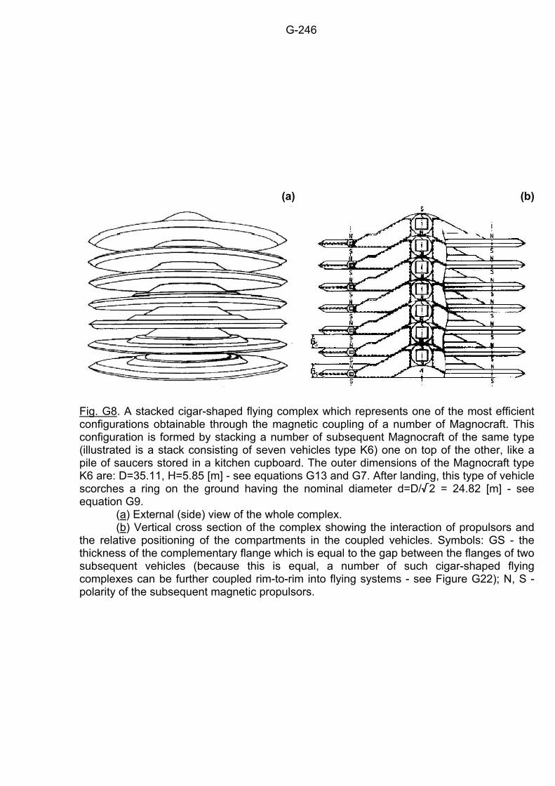
G-246
(a)
(b)
Fig. G8. A stacked cigar-shaped flying complex which represents one of the most efficient configurations obtainable through the magnetic coupling of a number of Magnocraft. This configuration is formed by stacking a number of subsequent Magnocraft of the same type (illustrated is a stack consisting of seven vehicles type K6) one on top of the other, like a pile of saucers stored in a kitchen cupboard. The outer dimensions of the Magnocraft type K6 are: D=35.11, H=5.85 [m] - see equations G13 and G7. After landing, this type of vehicle scorches a ring on the ground having the nominal diameter d=D//2 = 24.82 [m] - see equation G9. (a) External (side) view of the whole complex. (b) Vertical cross section of the complex showing the interaction of propulsors and the relative positioning of the compartments in the coupled vehicles. Symbols: GS - the thickness of the complementary flange which is equal to the gap between the flanges of two subsequent vehicles (because this is equal, a number of such cigar-shaped flying complexes can be further coupled rim-to-rim into flying systems - see Figure G22); N, S - polarity of the subsequent magnetic propulsors.
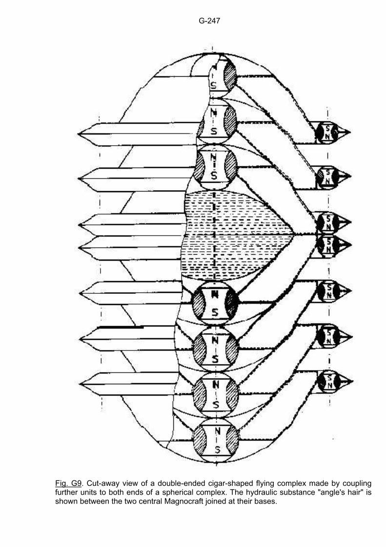
G-247
Fig. G9. Cut-away view of a double-ended cigar-shaped flying complex made by coupling further units to both ends of a spherical complex. The hydraulic substance "angle's hair" is shown between the two central Magnocraft joined at their bases.
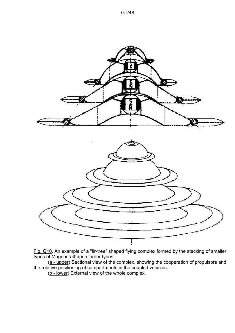
G-248
Fig. G10. An example of a "fir-tree" shaped flying complex formed by the stacking of smaller types of Magnocraft upon larger types. (a - upper) Sectional view of the complex, showing the cooperation of propulsors and the relative positioning of compartments in the coupled vehicles. (b - lower) External view of the whole complex.
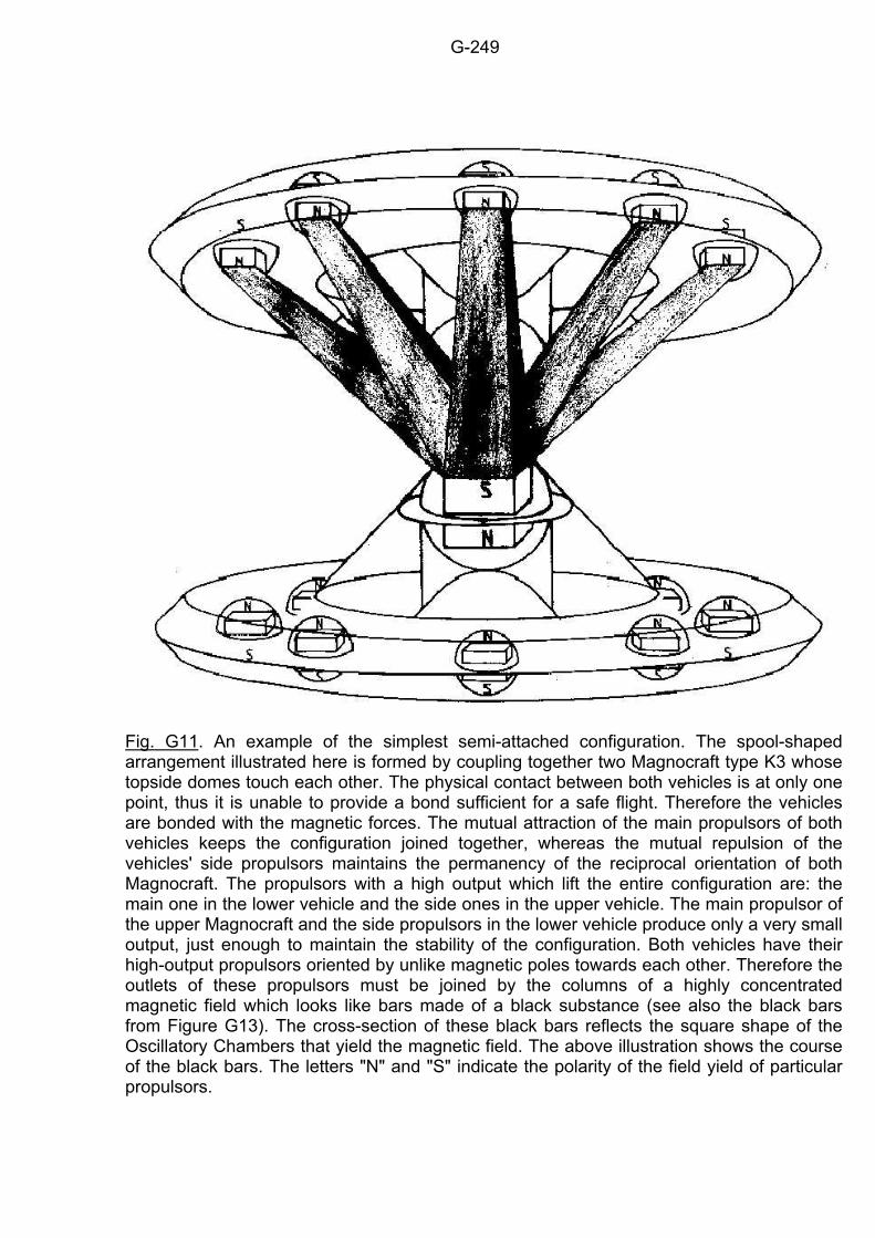
G-249
Fig. G11. An example of the simplest semi-attached configuration. The spool-shaped arrangement illustrated here is formed by coupling together two Magnocraft type K3 whose topside domes touch each other. The physical contact between both vehicles is at only one point, thus it is unable to provide a bond sufficient for a safe flight. Therefore the vehicles are bonded with the magnetic forces. The mutual attraction of the main propulsors of both vehicles keeps the configuration joined together, whereas the mutual repulsion of the vehicles' side propulsors maintains the permanency of the reciprocal orientation of both Magnocraft. The propulsors with a high output which lift the entire configuration are: the main one in the lower vehicle and the side ones in the upper vehicle. The main propulsor of the upper Magnocraft and the side propulsors in the lower vehicle produce only a very small output, just enough to maintain the stability of the configuration. Both vehicles have their high-output propulsors oriented by unlike magnetic poles towards each other. Therefore the outlets of these propulsors must be joined by the columns of a highly concentrated magnetic field which looks like bars made of a black substance (see also the black bars from Figure G13). The cross-section of these black bars reflects the square shape of the Oscillatory Chambers that yield the magnetic field. The above illustration shows the course of the black bars. The letters "N" and "S" indicate the polarity of the field yield of particular propulsors.
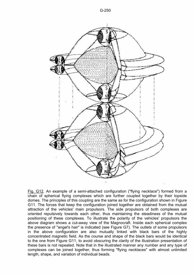
G-250
Fig. G12. An example of a semi-attached configuration ("flying necklace") formed from a chain of spherical flying complexes which are further coupled together by their topside domes. The principles of this coupling are the same as for the configuration shown in Figure G11. The forces that keep the configuration joined together are obtained from the mutual attraction of the vehicles' main propulsors. The side propulsors of both complexes are oriented repulsively towards each other, thus maintaining the steadiness of the mutual positioning of these complexes. To illustrate the polarity of the vehicles' propulsors the above diagram shows a cut-away view of the Magnocraft. Inside each spherical complex the presence of "angel's hair" is indicated (see Figure G7). The outlets of some propulsors in the above configuration are also mutually linked with black bars of the highly concentrated magnetic field. As the course and shape of the black bars would be identical to the one from Figure G11, to avoid obscuring the clarity of the illustration presentation of these bars is not repeated. Note that in the illustrated manner any number and any type of complexes can be joined together, thus forming "flying necklaces" with almost unlimited length, shape, and variation of individual beads.
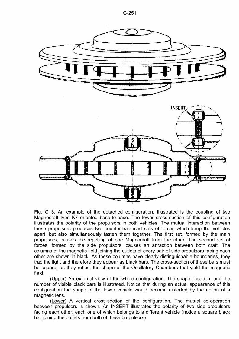
G-251
Fig. G13. An example of the detached configuration. Illustrated is the coupling of two Magnocraft type K7 oriented base-to-base. The lower cross-section of this configuration illustrates the polarity of the propulsors in both vehicles. The mutual interaction between these propulsors produces two counter-balanced sets of forces which keep the vehicles apart, but also simultaneously fasten them together. The first set, formed by the main propulsors, causes the repelling of one Magnocraft from the other. The second set of forces, formed by the side propulsors, causes an attraction between both craft. The columns of the magnetic field joining the outlets of every pair of side propulsors facing each other are shown in black. As these columns have clearly distinguishable boundaries, they trap the light and therefore they appear as black bars. The cross-section of these bars must be square, as they reflect the shape of the Oscillatory Chambers that yield the magnetic field. (Upper) An external view of the whole configuration. The shape, location, and the number of visible black bars is illustrated. Notice that during an actual appearance of this configuration the shape of the lower vehicle would become distorted by the action of a magnetic lens. (Lower) A vertical cross-section of the configuration. The mutual co-operation between propulsors is shown. An INSERT illustrates the polarity of two side propulsors facing each other, each one of which belongs to a different vehicle (notice a square black bar joining the outlets from both of these propulsors).
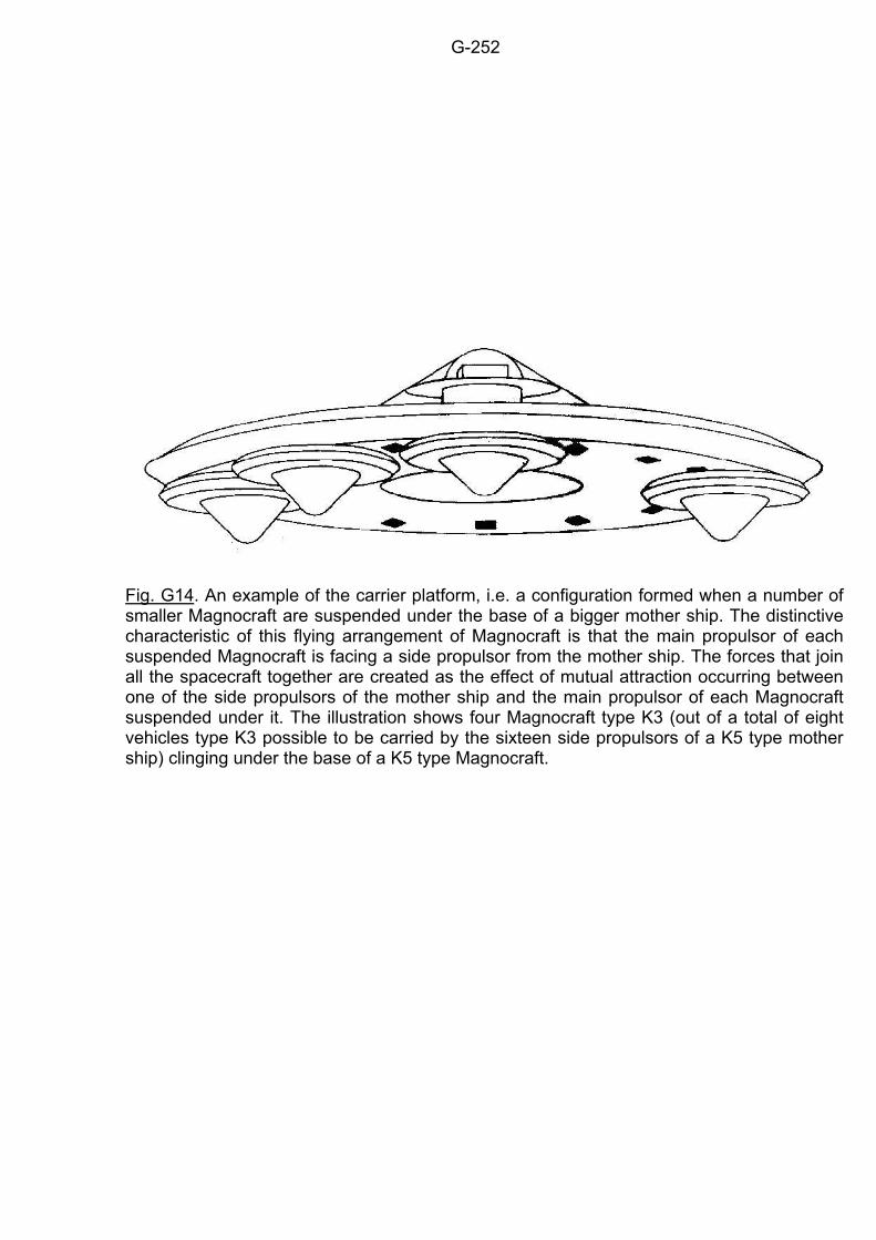
G-252
Fig. G14. An example of the carrier platform, i.e. a configuration formed when a number of smaller Magnocraft are suspended under the base of a bigger mother ship. The distinctive characteristic of this flying arrangement of Magnocraft is that the main propulsor of each suspended Magnocraft is facing a side propulsor from the mother ship. The forces that join all the spacecraft together are created as the effect of mutual attraction occurring between one of the side propulsors of the mother ship and the main propulsor of each Magnocraft suspended under it. The illustration shows four Magnocraft type K3 (out of a total of eight vehicles type K3 possible to be carried by the sixteen side propulsors of a K5 type mother ship) clinging under the base of a K5 type Magnocraft.
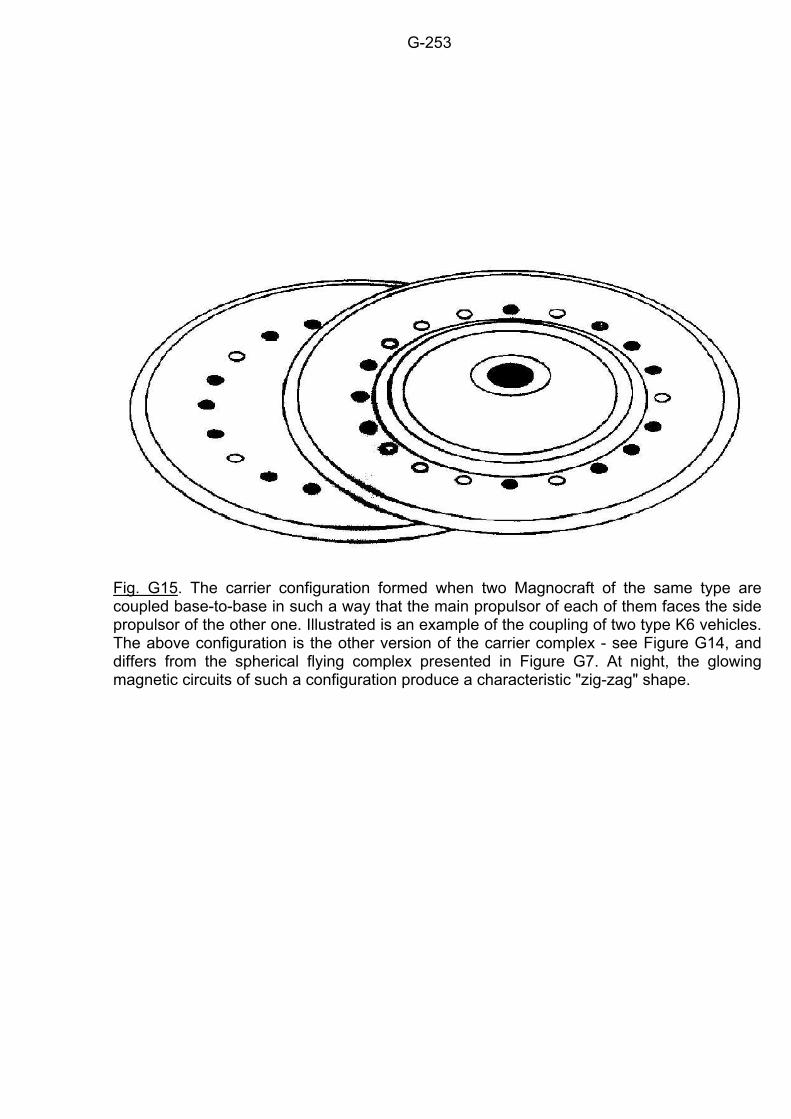
G-253
Fig. G15. The carrier configuration formed when two Magnocraft of the same type are coupled base-to-base in such a way that the main propulsor of each of them faces the side propulsor of the other one. Illustrated is an example of the coupling of two type K6 vehicles. The above configuration is the other version of the carrier complex - see Figure G14, and differs from the spherical flying complex presented in Figure G7. At night, the glowing magnetic circuits of such a configuration produce a characteristic "zig-zag" shape.
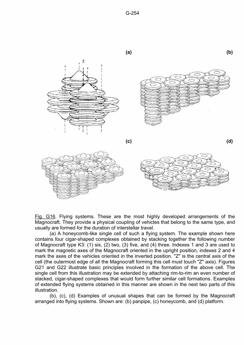
G-254
(a)
(b)
(c) (d)
Fig. G16. Flying systems. These are the most highly developed arrangements of the Magnocraft. They provide a physical coupling of vehicles that belong to the same type, and usually are formed for the duration of interstellar travel. (a) A honeycomb-like single cell of such a flying system. The example shown here contains four cigar-shaped complexes obtained by stacking together the following number of Magnocraft type K3: (1) six, (2) two, (3) five, and (4) three. Indexes 1 and 3 are used to mark the magnetic axes of the Magnocraft oriented in the upright position, indexes 2 and 4 mark the axes of the vehicles oriented in the inverted position. "Z" is the central axis of the cell (the outermost edge of all the Magnocraft forming this cell must touch "Z" axis). Figures G21 and G22 illustrate basic principles involved in the formation of the above cell. The single cell from this illustration may be extended by attaching rim-to-rim an even number of stacked, cigar-shaped complexes that would form further similar cell formations. Examples of extended flying systems obtained in this manner are shown in the next two parts of this illustration. (b), (c), (d) Examples of unusual shapes that can be formed by the Magnocraft arranged into flying systems. Shown are: (b) panpipe, (c) honeycomb, and (d) platform.
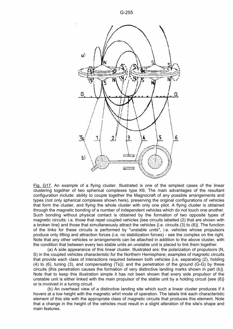
G-255
Fig. G17. An example of a flying cluster. Illustrated is one of the simplest cases of the linear clustering together of two spherical complexes type K6. The main advantages of the resultant configuration include: ability to couple together the Magnocraft of any possible arrangements and types (not only spherical complexes shown here), preserving the original configurations of vehicles that form the cluster, and flying the whole cluster with only one pilot. A flying cluster is obtained through the magnetic bonding of a number of independent vehicles which do not touch one another. Such bonding without physical contact is obtained by the formation of two opposite types of magnetic circuits: i.e. those that repel coupled vehicles see circuits labelled (2) that are shown with a broken line and those that simultaneously attract the vehicles i.e. circuits (3) to (6). The function of the links for these circuits is performed by "unstable units", i.e. vehicles whose propulsors produce only lifting and attraction forces (i.e. no stabilization forces) - see the complex on the right. Note that any other vehicles or arrangements can be attached in addition to the above cluster, with the condition that between every two stable units an unstable unit is placed to link them together. (a) A side appearance of this linear cluster. Illustrated are: the polarization of propulsors (N, S) in the coupled vehicles characteristic for the Northern Hemisphere; examples of magnetic circuits that provide each class of interactions required between both vehicles i.e. separating (2), holding (4) to (6), tuning (3), and compensating (Ts); and the penetration of the ground (G-G) by these circuits this penetration causes the formation of very distinctive landing marks shown in part (b). Note that to keep this illustration simple it has not been shown that every side propulsor of the unstable unit is either linked with the main propulsor of the stable unit by a holding circuit see (6) or is involved in a tuning circuit. (b) An overhead view of a distinctive landing site which such a linear cluster produces if it hovers at a low height with the magnetic whirl mode of operation. The labels link each characteristic element of this site with the appropriate class of magnetic circuits that produces this element. Note that a change in the height of the vehicles must result in a slight alteration of the site's shape and main features.
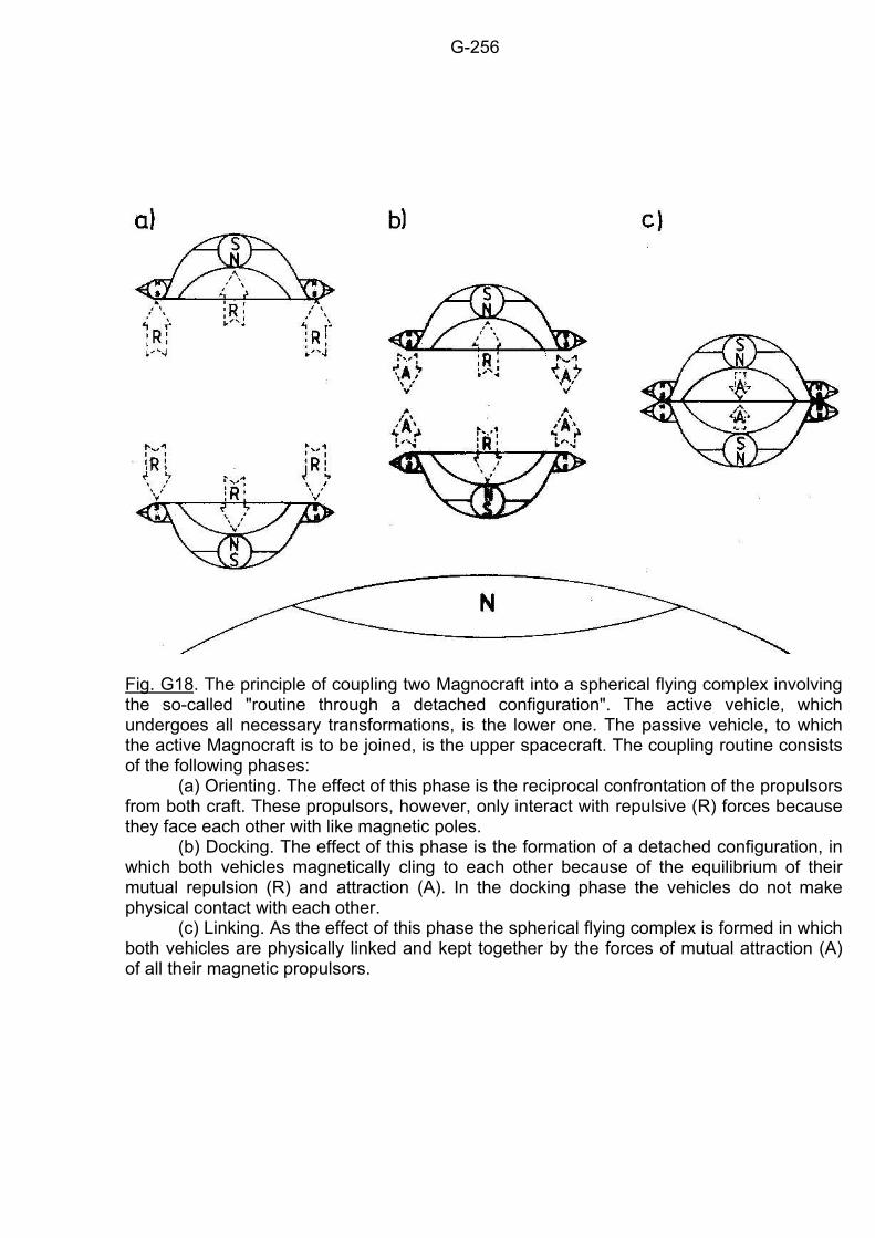
G-256
Fig. G18. The principle of coupling two Magnocraft into a spherical flying complex involving the so-called "routine through a detached configuration". The active vehicle, which undergoes all necessary transformations, is the lower one. The passive vehicle, to which the active Magnocraft is to be joined, is the upper spacecraft. The coupling routine consists of the following phases: (a) Orienting. The effect of this phase is the reciprocal confrontation of the propulsors from both craft. These propulsors, however, only interact with repulsive (R) forces because they face each other with like magnetic poles. (b) Docking. The effect of this phase is the formation of a detached configuration, in which both vehicles magnetically cling to each other because of the equilibrium of their mutual repulsion (R) and attraction (A). In the docking phase the vehicles do not make physical contact with each other. (c) Linking. As the effect of this phase the spherical flying complex is formed in which both vehicles are physically linked and kept together by the forces of mutual attraction (A) of all their magnetic propulsors.
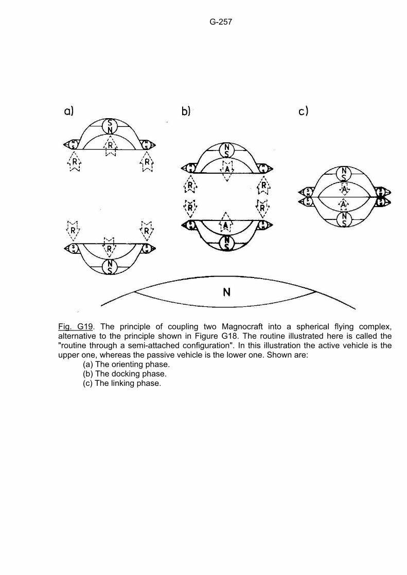
G-257
Fig. G19. The principle of coupling two Magnocraft into a spherical flying complex, alternative to the principle shown in Figure G18. The routine illustrated here is called the "routine through a semi-attached configuration". In this illustration the active vehicle is the upper one, whereas the passive vehicle is the lower one. Shown are: (a) The orienting phase. (b) The docking phase. (c) The linking phase.
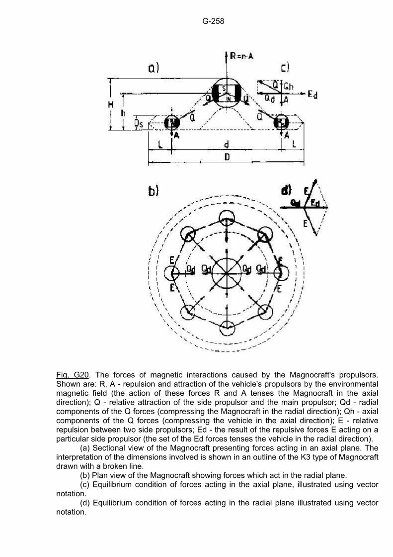
G-258
Fig. G20. The forces of magnetic interactions caused by the Magnocraft's propulsors. Shown are: R, A - repulsion and attraction of the vehicle's propulsors by the environmental magnetic field (the action of these forces R and A tenses the Magnocraft in the axial direction); Q - relative attraction of the side propulsor and the main propulsor; Qd - radial components of the Q forces (compressing the Magnocraft in the radial direction); Qh - axial components of the Q forces (compressing the vehicle in the axial direction); E - relative repulsion between two side propulsors; Ed - the result of the repulsive forces E acting on a particular side propulsor (the set of the Ed forces tenses the vehicle in the radial direction). (a) Sectional view of the Magnocraft presenting forces acting in an axial plane. The interpretation of the dimensions involved is shown in an outline of the K3 type of Magnocraft drawn with a broken line. (b) Plan view of the Magnocraft showing forces which act in the radial plane. (c) Equilibrium condition of forces acting in the axial plane, illustrated using vector notation. (d) Equilibrium condition of forces acting in the radial plane illustrated using vector notation.
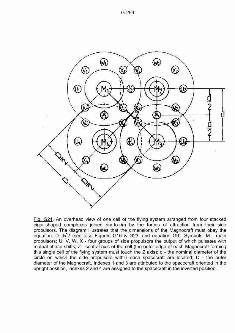
G-259
Fig. G21. An overhead view of one cell of the flying system arranged from four stacked cigar-shaped complexes joined rim-to-rim by the forces of attraction from their side propulsors. The diagram illustrates that the dimensions of the Magnocraft must obey the equation: D=d/2 (see also Figures G16 & G23, and equation G9). Symbols: M - main propulsors; U, V, W, X - four groups of side propulsors the output of which pulsates with mutual phase shifts; Z - central axis of the cell (the outer edge of each Magnocraft forming this single cell of the flying system must touch the Z axis); d - the nominal diameter of the circle on which the side propulsors within each spacecraft are located; D - the outer diameter of the Magnocraft. Indexes 1 and 3 are attributed to the spacecraft oriented in the upright position, indexes 2 and 4 are assigned to the spacecraft in the inverted position.
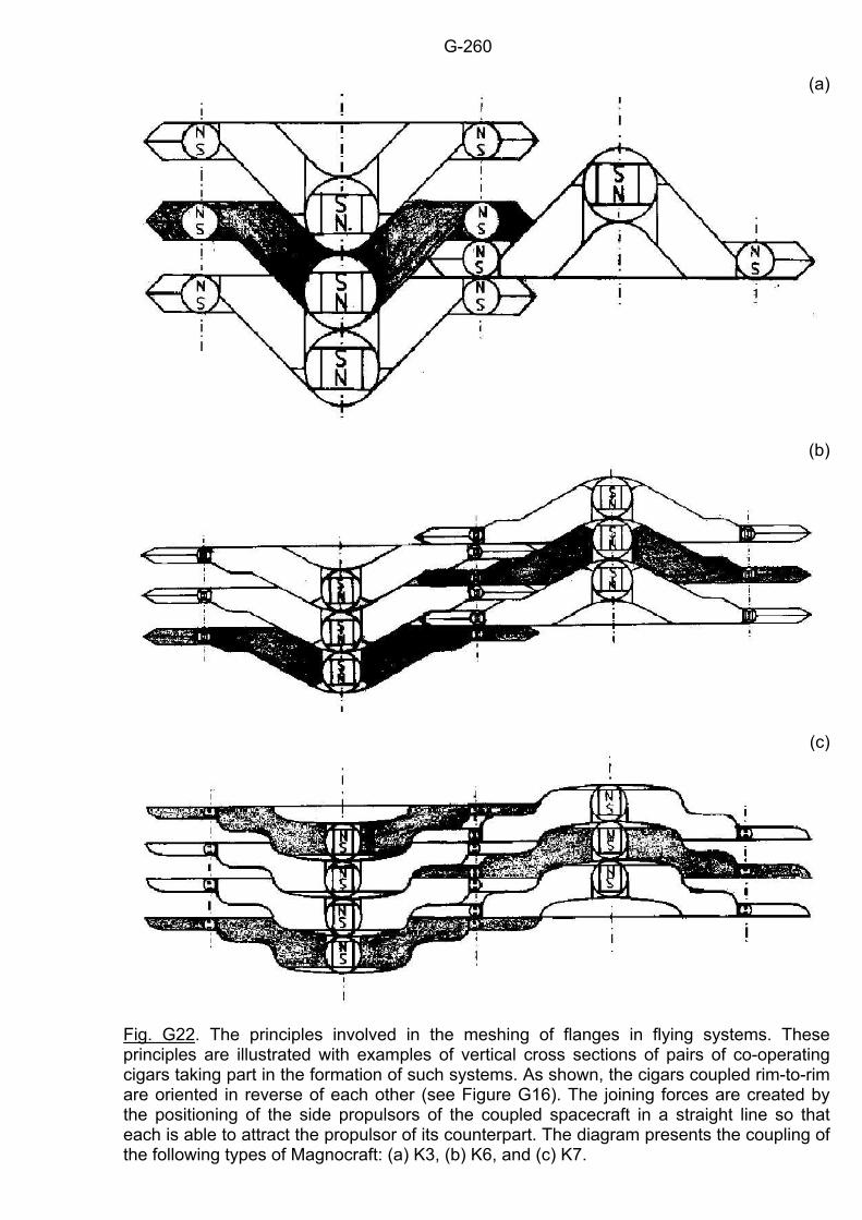
G-260
(a)
(b)
(c)
Fig. G22. The principles involved in the meshing of flanges in flying systems. These principles are illustrated with examples of vertical cross sections of pairs of co-operating cigars taking part in the formation of such systems. As shown, the cigars coupled rim-to-rim are oriented in reverse of each other (see Figure G16). The joining forces are created by the positioning of the side propulsors of the coupled spacecraft in a straight line so that each is able to attract the propulsor of its counterpart. The diagram presents the coupling of the following types of Magnocraft: (a) K3, (b) K6, and (c) K7.
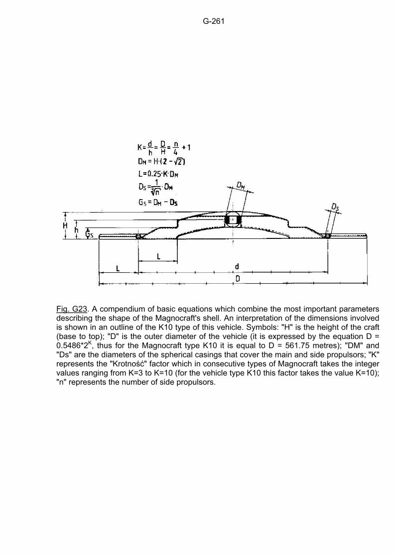
G-261
Fig. G23. A compendium of basic equations which combine the most important parameters describing the shape of the Magnocraft's shell. An interpretation of the dimensions involved is shown in an outline of the K10 type of this vehicle. Symbols: "H" is the height of the craft (base to top); "D" is the outer diameter of the vehicle (it is expressed by the equation D = 0.5486*2K, thus for the Magnocraft type K10 it is equal to D = 561.75 metres); "DM" and "Ds" are the diameters of the spherical casings that cover the main and side propulsors; "K" represents the "Krotność" factor which in consecutive types of Magnocraft takes the integer values ranging from K=3 to K=10 (for the vehicle type K10 this factor takes the value K=10); "n" represents the number of side propulsors.
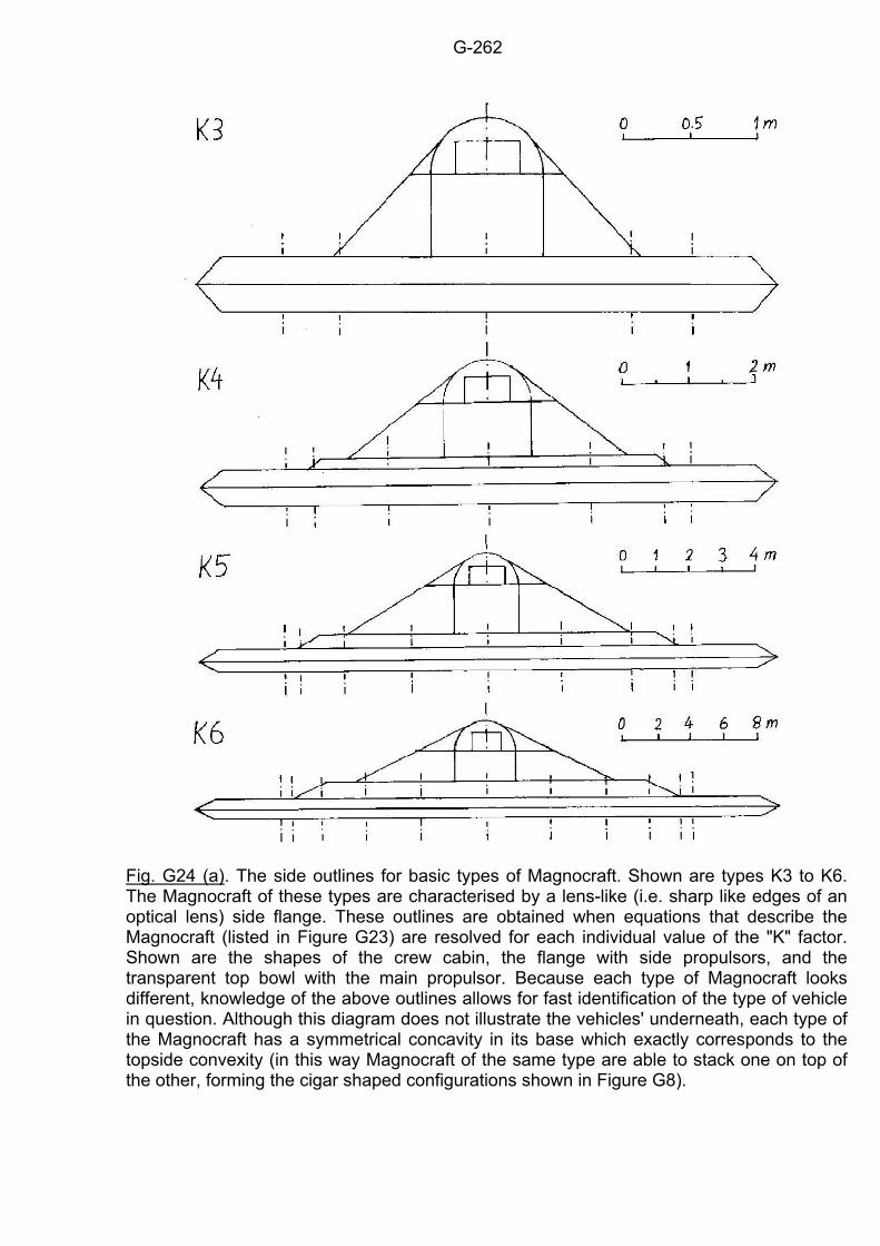
G-262
Fig. G24 (a). The side outlines for basic types of Magnocraft. Shown are types K3 to K6. The Magnocraft of these types are characterised by a lens-like (i.e. sharp like edges of an optical lens) side flange. These outlines are obtained when equations that describe the Magnocraft (listed in Figure G23) are resolved for each individual value of the "K" factor. Shown are the shapes of the crew cabin, the flange with side propulsors, and the transparent top bowl with the main propulsor. Because each type of Magnocraft looks different, knowledge of the above outlines allows for fast identification of the type of vehicle in question. Although this diagram does not illustrate the vehicles' underneath, each type of the Magnocraft has a symmetrical concavity in its base which exactly corresponds to the topside convexity (in this way Magnocraft of the same type are able to stack one on top of the other, forming the cigar shaped configurations shown in Figure G8).
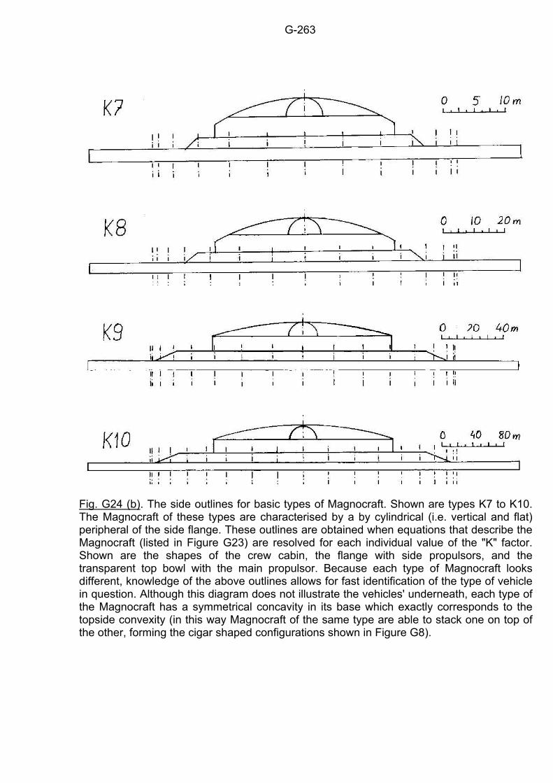
G-263
Fig. G24 (b). The side outlines for basic types of Magnocraft. Shown are types K7 to K10. The Magnocraft of these types are characterised by a by cylindrical (i.e. vertical and flat) peripheral of the side flange. These outlines are obtained when equations that describe the Magnocraft (listed in Figure G23) are resolved for each individual value of the "K" factor. Shown are the shapes of the crew cabin, the flange with side propulsors, and the transparent top bowl with the main propulsor. Because each type of Magnocraft looks different, knowledge of the above outlines allows for fast identification of the type of vehicle in question. Although this diagram does not illustrate the vehicles' underneath, each type of the Magnocraft has a symmetrical concavity in its base which exactly corresponds to the topside convexity (in this way Magnocraft of the same type are able to stack one on top of the other, forming the cigar shaped configurations shown in Figure G8).
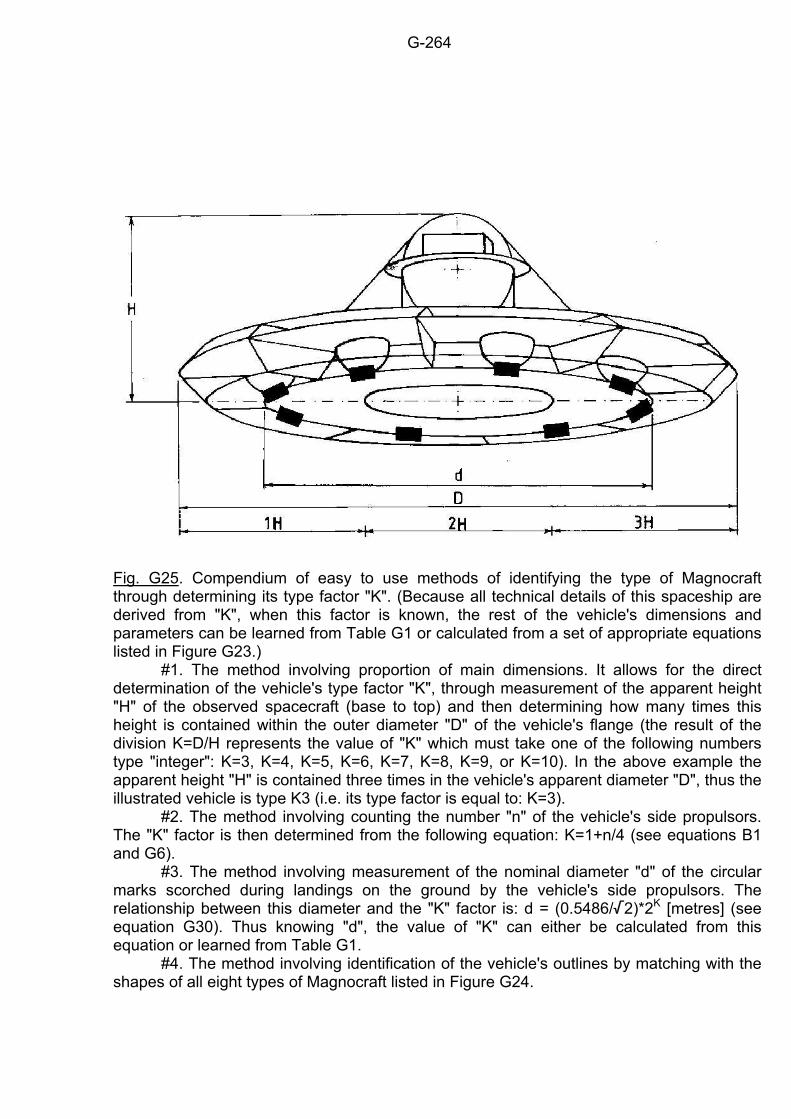
G-264
Fig. G25. Compendium of easy to use methods of identifying the type of Magnocraft through determining its type factor "K". (Because all technical details of this spaceship are derived from "K", when this factor is known, the rest of the vehicle's dimensions and parameters can be learned from Table G1 or calculated from a set of appropriate equations listed in Figure G23.) #1. The method involving proportion of main dimensions. It allows for the direct determination of the vehicle's type factor "K", through measurement of the apparent height "H" of the observed spacecraft (base to top) and then determining how many times this height is contained within the outer diameter "D" of the vehicle's flange (the result of the division K=D/H represents the value of "K" which must take one of the following numbers type "integer": K=3, K=4, K=5, K=6, K=7, K=8, K=9, or K=10). In the above example the apparent height "H" is contained three times in the vehicle's apparent diameter "D", thus the illustrated vehicle is type K3 (i.e. its type factor is equal to: K=3). #2. The method involving counting the number "n" of the vehicle's side propulsors. The "K" factor is then determined from the following equation: K=1+n/4 (see equations B1 and G6). #3. The method involving measurement of the nominal diameter "d" of the circular marks scorched during landings on the ground by the vehicle's side propulsors. The relationship between this diameter and the "K" factor is: d = (0.5486//2)*2K [metres] (see equation G30). Thus knowing "d", the value of "K" can either be calculated from this equation or learned from Table G1. #4. The method involving identification of the vehicle's outlines by matching with the shapes of all eight types of Magnocraft listed in Figure G24.
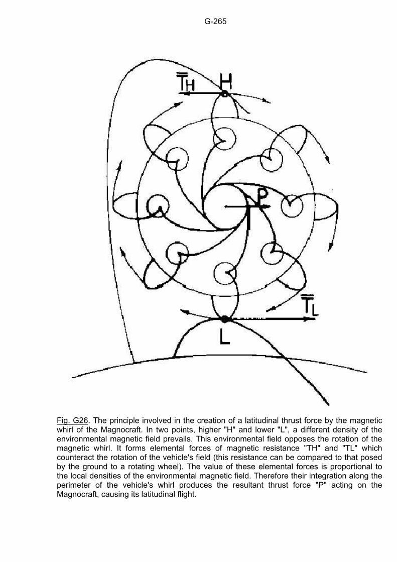
G-265
Fig. G26. The principle involved in the creation of a latitudinal thrust force by the magnetic whirl of the Magnocraft. In two points, higher "H" and lower "L", a different density of the environmental magnetic field prevails. This environmental field opposes the rotation of the magnetic whirl. It forms elemental forces of magnetic resistance "TH" and "TL" which counteract the rotation of the vehicle's field (this resistance can be compared to that posed by the ground to a rotating wheel). The value of these elemental forces is proportional to the local densities of the environmental magnetic field. Therefore their integration along the perimeter of the vehicle's whirl produces the resultant thrust force "P" acting on the Magnocraft, causing its latitudinal flight.
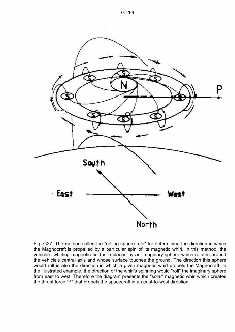
G-266
Fig. G27. The method called the "rolling sphere rule" for determining the direction in which the Magnocraft is propelled by a particular spin of its magnetic whirl. In this method, the vehicle's whirling magnetic field is replaced by an imaginary sphere which rotates around the vehicle's central axis and whose surface touches the ground. The direction this sphere would roll is also the direction in which a given magnetic whirl propels the Magnocraft. In the illustrated example, the direction of the whirl's spinning would "roll" the imaginary sphere from east to west. Therefore the diagram presents the "solar" magnetic whirl which creates the thrust force "P" that propels the spacecraft in an east-to-west direction.
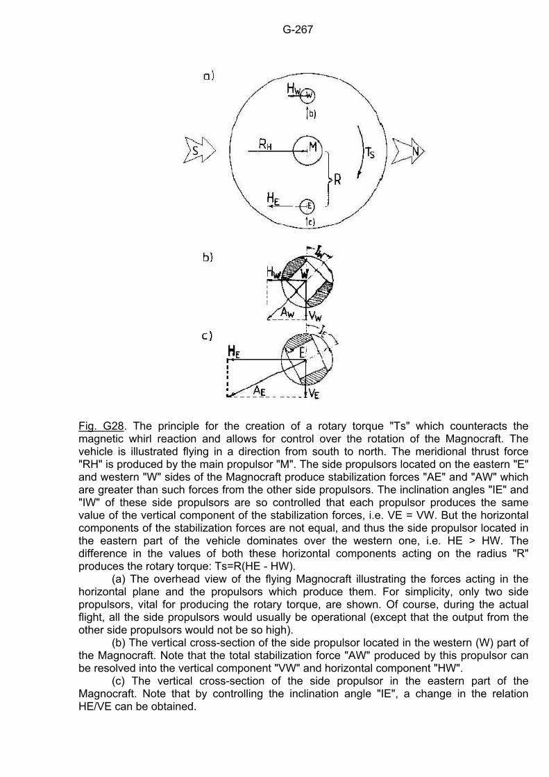
G-267
Fig. G28. The principle for the creation of a rotary torque "Ts" which counteracts the magnetic whirl reaction and allows for control over the rotation of the Magnocraft. The vehicle is illustrated flying in a direction from south to north. The meridional thrust force "RH" is produced by the main propulsor "M". The side propulsors located on the eastern "E" and western "W" sides of the Magnocraft produce stabilization forces "AE" and "AW" which are greater than such forces from the other side propulsors. The inclination angles "IE" and "IW" of these side propulsors are so controlled that each propulsor produces the same value of the vertical component of the stabilization forces, i.e. VE = VW. But the horizontal components of the stabilization forces are not equal, and thus the side propulsor located in the eastern part of the vehicle dominates over the western one, i.e. HE > HW. The difference in the values of both these horizontal components acting on the radius "R" produces the rotary torque: Ts=R(HE - HW). (a) The overhead view of the flying Magnocraft illustrating the forces acting in the horizontal plane and the propulsors which produce them. For simplicity, only two side propulsors, vital for producing the rotary torque, are shown. Of course, during the actual flight, all the side propulsors would usually be operational (except that the output from the other side propulsors would not be so high). (b) The vertical cross-section of the side propulsor located in the western (W) part of the Magnocraft. Note that the total stabilization force "AW" produced by this propulsor can be resolved into the vertical component "VW" and horizontal component "HW". (c) The vertical cross-section of the side propulsor in the eastern part of the Magnocraft. Note that by controlling the inclination angle "IE", a change in the relation HE/VE can be obtained.
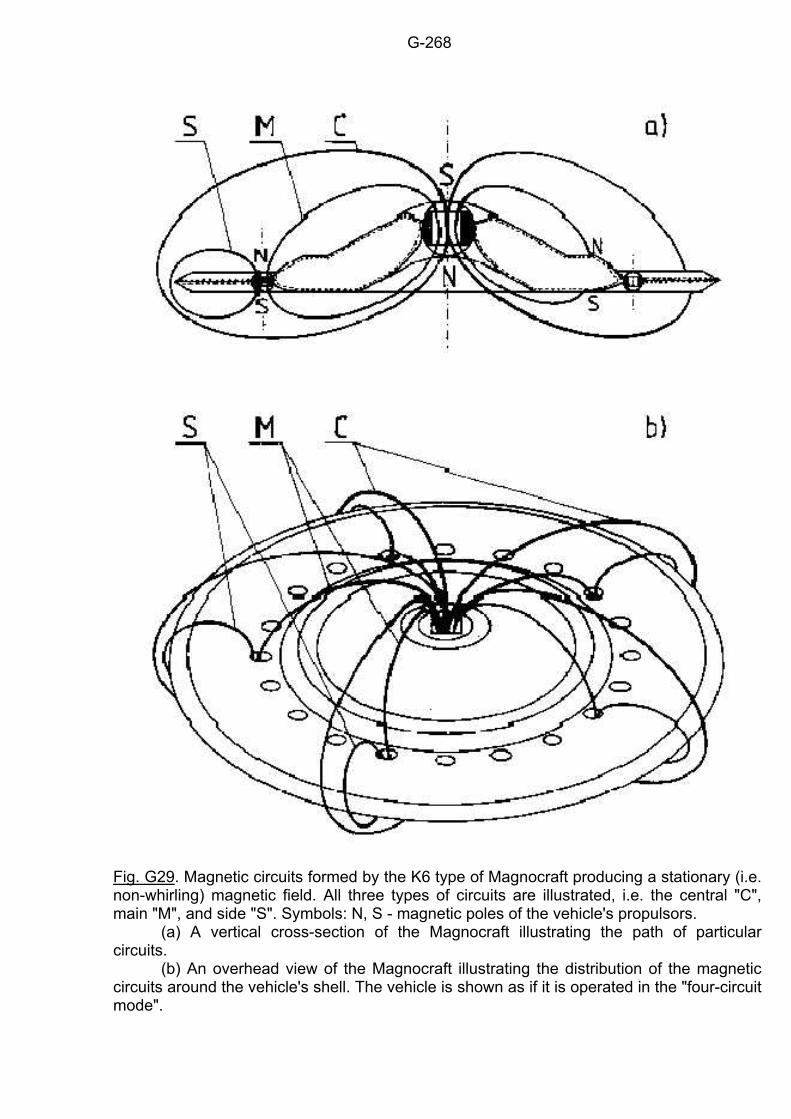
G-268
Fig. G29. Magnetic circuits formed by the K6 type of Magnocraft producing a stationary (i.e. non-whirling) magnetic field. All three types of circuits are illustrated, i.e. the central "C", main "M", and side "S". Symbols: N, S - magnetic poles of the vehicle's propulsors. (a) A vertical cross-section of the Magnocraft illustrating the path of particular circuits. (b) An overhead view of the Magnocraft illustrating the distribution of the magnetic circuits around the vehicle's shell. The vehicle is shown as if it is operated in the "four-circuit mode".
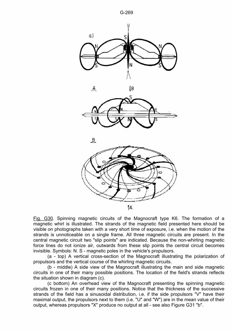
G-269
Fig. G30. Spinning magnetic circuits of the Magnocraft type K6. The formation of a magnetic whirl is illustrated. The strands of the magnetic field presented here should be visible on photographs taken with a very short time of exposure, i.e. when the motion of the strands is unnoticeable on a single frame. All three magnetic circuits are present. In the central magnetic circuit two "slip points" are indicated. Because the non-whirling magnetic force lines do not ionize air, outwards from these slip points the central circuit becomes invisible. Symbols: N. S - magnetic poles in the vehicle's propulsors. (a - top) A vertical cross-section of the Magnocraft illustrating the polarization of propulsors and the vertical course of the whirling magnetic circuits. (b - middle) A side view of the Magnocraft illustrating the main and side magnetic circuits in one of their many possible positions. The location of the field's strands reflects the situation shown in diagram (c). (c bottom) An overhead view of the Magnocraft presenting the spinning magnetic circuits frozen in one of their many positions. Notice that the thickness of the successive strands of the field has a sinusoidal distribution, i.e. if the side propulsors "V" have their maximal output, the propulsors next to them (i.e. "U" and "W") are in the mean value of their output, whereas propulsors "X" produce no output at all - see also Figure G31 "b".
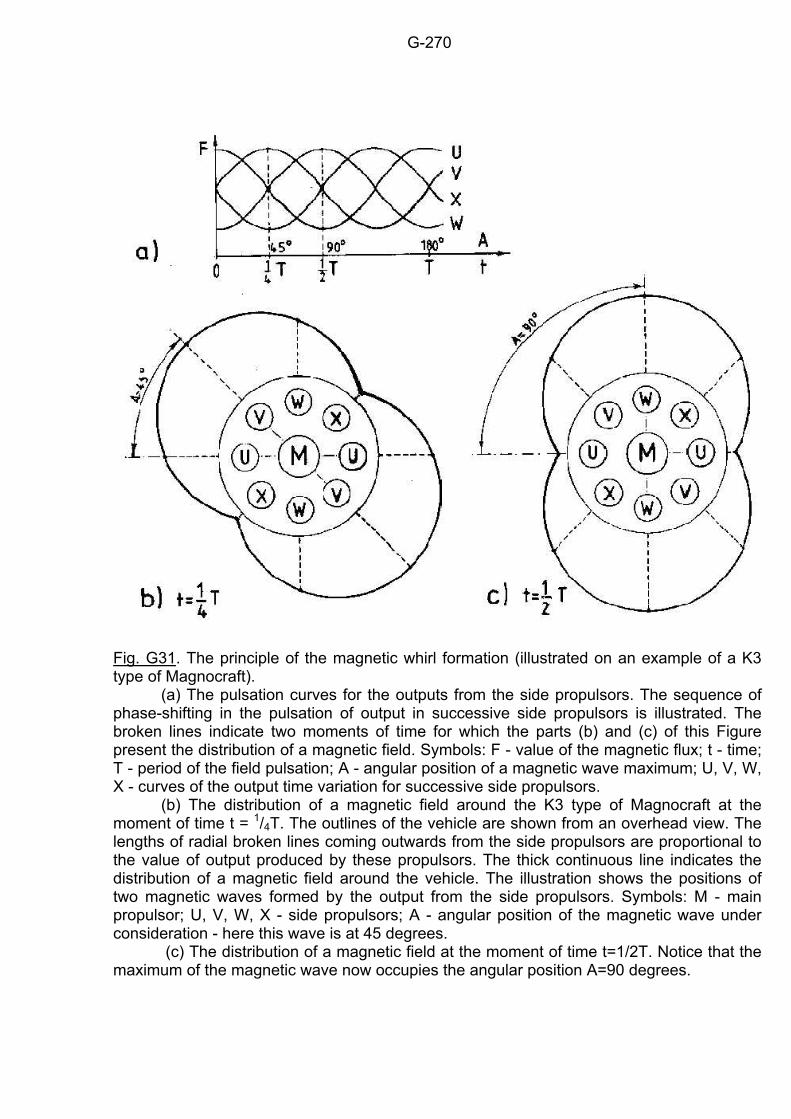
G-270
Fig. G31. The principle of the magnetic whirl formation (illustrated on an example of a K3 type of Magnocraft). (a) The pulsation curves for the outputs from the side propulsors. The sequence of phase-shifting in the pulsation of output in successive side propulsors is illustrated. The broken lines indicate two moments of time for which the parts (b) and (c) of this Figure present the distribution of a magnetic field. Symbols: F - value of the magnetic flux; t - time; T - period of the field pulsation; A - angular position of a magnetic wave maximum; U, V, W, X - curves of the output time variation for successive side propulsors. (b) The distribution of a magnetic field around the K3 type of Magnocraft at the moment of time t = 1/4T. The outlines of the vehicle are shown from an overhead view. The lengths of radial broken lines coming outwards from the side propulsors are proportional to the value of output produced by these propulsors. The thick continuous line indicates the distribution of a magnetic field around the vehicle. The illustration shows the positions of two magnetic waves formed by the output from the side propulsors. Symbols: M - main propulsor; U, V, W, X - side propulsors; A - angular position of the magnetic wave under consideration - here this wave is at 45 degrees. (c) The distribution of a magnetic field at the moment of time t=1/2T. Notice that the maximum of the magnetic wave now occupies the angular position A=90 degrees.
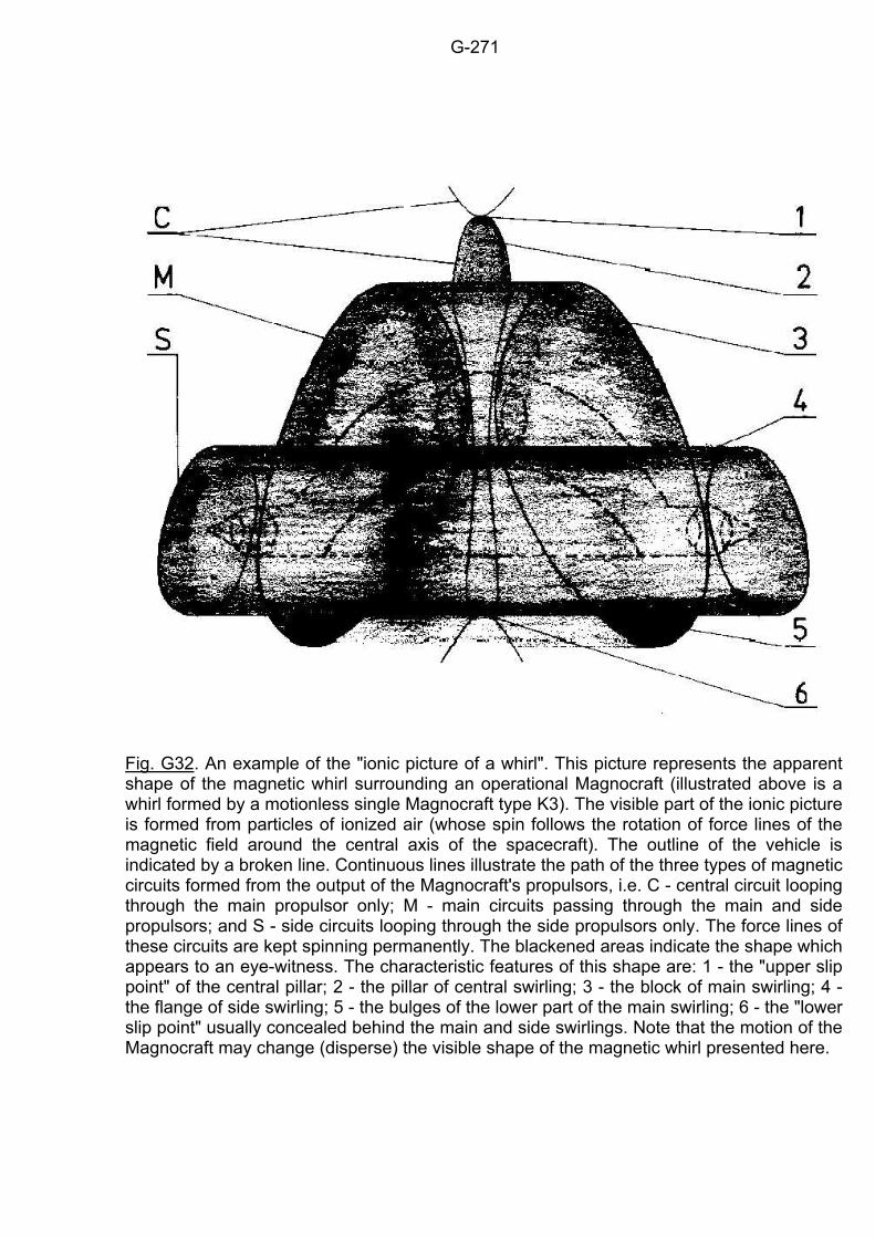
G-271
Fig. G32. An example of the "ionic picture of a whirl". This picture represents the apparent shape of the magnetic whirl surrounding an operational Magnocraft (illustrated above is a whirl formed by a motionless single Magnocraft type K3). The visible part of the ionic picture is formed from particles of ionized air (whose spin follows the rotation of force lines of the magnetic field around the central axis of the spacecraft). The outline of the vehicle is indicated by a broken line. Continuous lines illustrate the path of the three types of magnetic circuits formed from the output of the Magnocraft's propulsors, i.e. C - central circuit looping through the main propulsor only; M - main circuits passing through the main and side propulsors; and S - side circuits looping through the side propulsors only. The force lines of these circuits are kept spinning permanently. The blackened areas indicate the shape which appears to an eye-witness. The characteristic features of this shape are: 1 - the "upper slip point" of the central pillar; 2 - the pillar of central swirling; 3 - the block of main swirling; 4 - the flange of side swirling; 5 - the bulges of the lower part of the main swirling; 6 - the "lower slip point" usually concealed behind the main and side swirlings. Note that the motion of the Magnocraft may change (disperse) the visible shape of the magnetic whirl presented here.
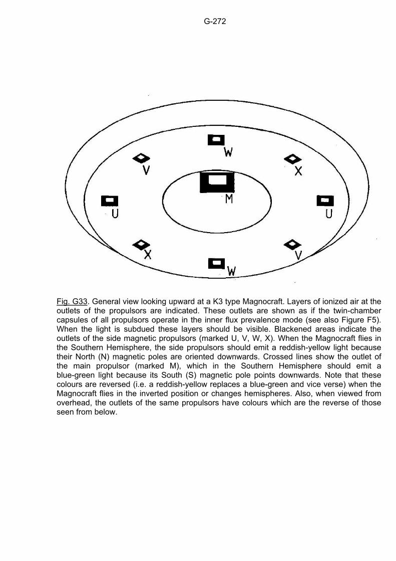
G-272
Fig. G33. General view looking upward at a K3 type Magnocraft. Layers of ionized air at the outlets of the propulsors are indicated. These outlets are shown as if the twin-chamber capsules of all propulsors operate in the inner flux prevalence mode (see also Figure F5). When the light is subdued these layers should be visible. Blackened areas indicate the outlets of the side magnetic propulsors (marked U, V, W, X). When the Magnocraft flies in the Southern Hemisphere, the side propulsors should emit a reddish-yellow light because their North (N) magnetic poles are oriented downwards. Crossed lines show the outlet of the main propulsor (marked M), which in the Southern Hemisphere should emit a blue-green light because its South (S) magnetic pole points downwards. Note that these colours are reversed (i.e. a reddish-yellow replaces a blue-green and vice verse) when the Magnocraft flies in the inverted position or changes hemispheres. Also, when viewed from overhead, the outlets of the same propulsors have colours which are the reverse of those seen from below.
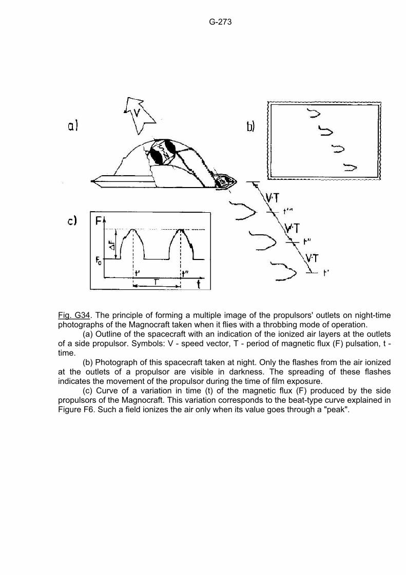
G-273
Fig. G34. The principle of forming a multiple image of the propulsors' outlets on night-time photographs of the Magnocraft taken when it flies with a throbbing mode of operation. (a) Outline of the spacecraft with an indication of the ionized air layers at the outlets of a side propulsor. Symbols: V - speed vector, T - period of magnetic flux (F) pulsation, t - time. (b) Photograph of this spacecraft taken at night. Only the flashes from the air ionized at the outlets of a propulsor are visible in darkness. The spreading of these flashes indicates the movement of the propulsor during the time of film exposure. (c) Curve of a variation in time (t) of the magnetic flux (F) produced by the side propulsors of the Magnocraft. This variation corresponds to the beat-type curve explained in Figure F6. Such a field ionizes the air only when its value goes through a "peak".
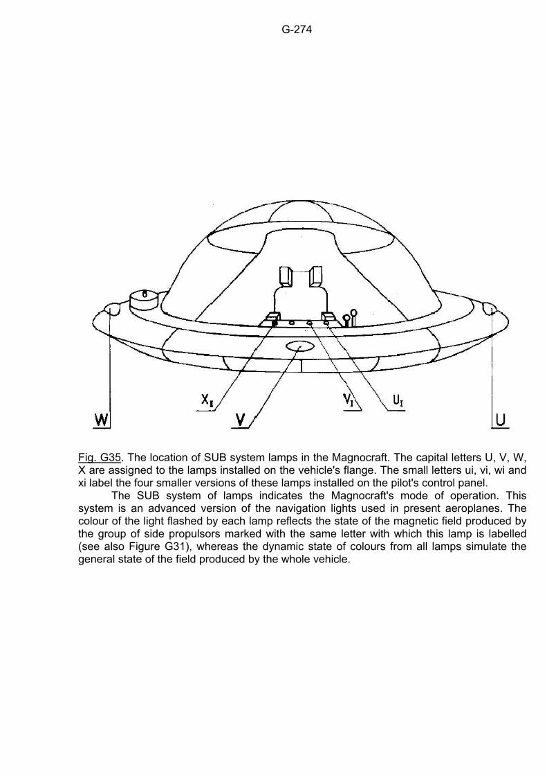
G-274
Fig. G35. The location of SUB system lamps in the Magnocraft. The capital letters U, V, W, X are assigned to the lamps installed on the vehicle's flange. The small letters ui, vi, wi and xi label the four smaller versions of these lamps installed on the pilot's control panel. The SUB system of lamps indicates the Magnocraft's mode of operation. This system is an advanced version of the navigation lights used in present aeroplanes. The colour of the light flashed by each lamp reflects the state of the magnetic field produced by the group of side propulsors marked with the same letter with which this lamp is labelled (see also Figure G31), whereas the dynamic state of colours from all lamps simulate the general state of the field produced by the whole vehicle.
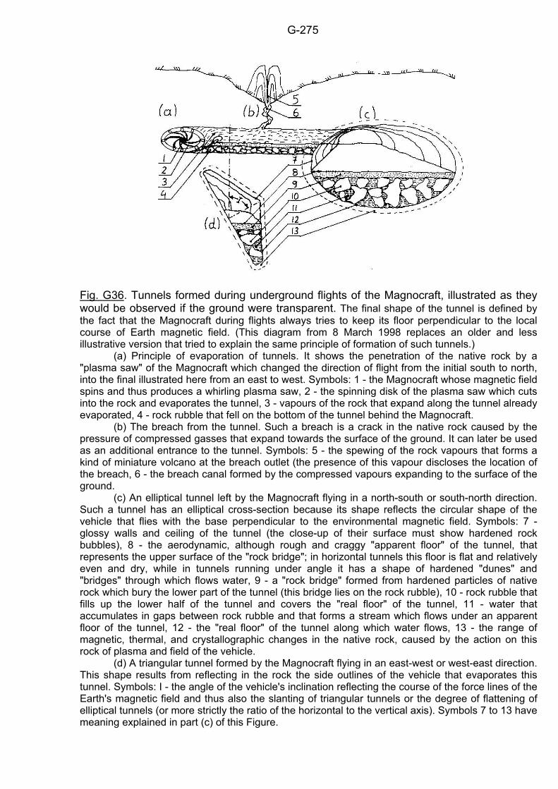
G-275
Fig. G36. Tunnels formed during underground flights of the Magnocraft, illustrated as they would be observed if the ground were transparent. The final shape of the tunnel is defined by the fact that the Magnocraft during flights always tries to keep its floor perpendicular to the local course of Earth magnetic field. (This diagram from 8 March 1998 replaces an older and less illustrative version that tried to explain the same principle of formation of such tunnels.) (a) Principle of evaporation of tunnels. It shows the penetration of the native rock by a "plasma saw" of the Magnocraft which changed the direction of flight from the initial south to north, into the final illustrated here from an east to west. Symbols: 1 - the Magnocraft whose magnetic field spins and thus produces a whirling plasma saw, 2 - the spinning disk of the plasma saw which cuts into the rock and evaporates the tunnel, 3 - vapours of the rock that expand along the tunnel already evaporated, 4 - rock rubble that fell on the bottom of the tunnel behind the Magnocraft. (b) The breach from the tunnel. Such a breach is a crack in the native rock caused by the pressure of compressed gasses that expand towards the surface of the ground. It can later be used as an additional entrance to the tunnel. Symbols: 5 - the spewing of the rock vapours that forms a kind of miniature volcano at the breach outlet (the presence of this vapour discloses the location of the breach, 6 - the breach canal formed by the compressed vapours expanding to the surface of the ground. (c) An elliptical tunnel left by the Magnocraft flying in a north-south or south-north direction. Such a tunnel has an elliptical cross-section because its shape reflects the circular shape of the vehicle that flies with the base perpendicular to the environmental magnetic field. Symbols: 7 - glossy walls and ceiling of the tunnel (the close-up of their surface must show hardened rock bubbles), 8 - the aerodynamic, although rough and craggy "apparent floor" of the tunnel, that represents the upper surface of the "rock bridge"; in horizontal tunnels this floor is flat and relatively even and dry, while in tunnels running under angle it has a shape of hardened "dunes" and "bridges" through which flows water, 9 - a "rock bridge" formed from hardened particles of native rock which bury the lower part of the tunnel (this bridge lies on the rock rubble), 10 - rock rubble that fills up the lower half of the tunnel and covers the "real floor" of the tunnel, 11 - water that accumulates in gaps between rock rubble and that forms a stream which flows under an apparent floor of the tunnel, 12 - the "real floor" of the tunnel along which water flows, 13 - the range of magnetic, thermal, and crystallographic changes in the native rock, caused by the action on this rock of plasma and field of the vehicle. (d) A triangular tunnel formed by the Magnocraft flying in an east-west or west-east direction. This shape results from reflecting in the rock the side outlines of the vehicle that evaporates this tunnel. Symbols: I - the angle of the vehicle's inclination reflecting the course of the force lines of the Earth's magnetic field and thus also the slanting of triangular tunnels or the degree of flattening of elliptical tunnels (or more strictly the ratio of the horizontal to the vertical axis). Symbols 7 to 13 have meaning explained in part (c) of this Figure.
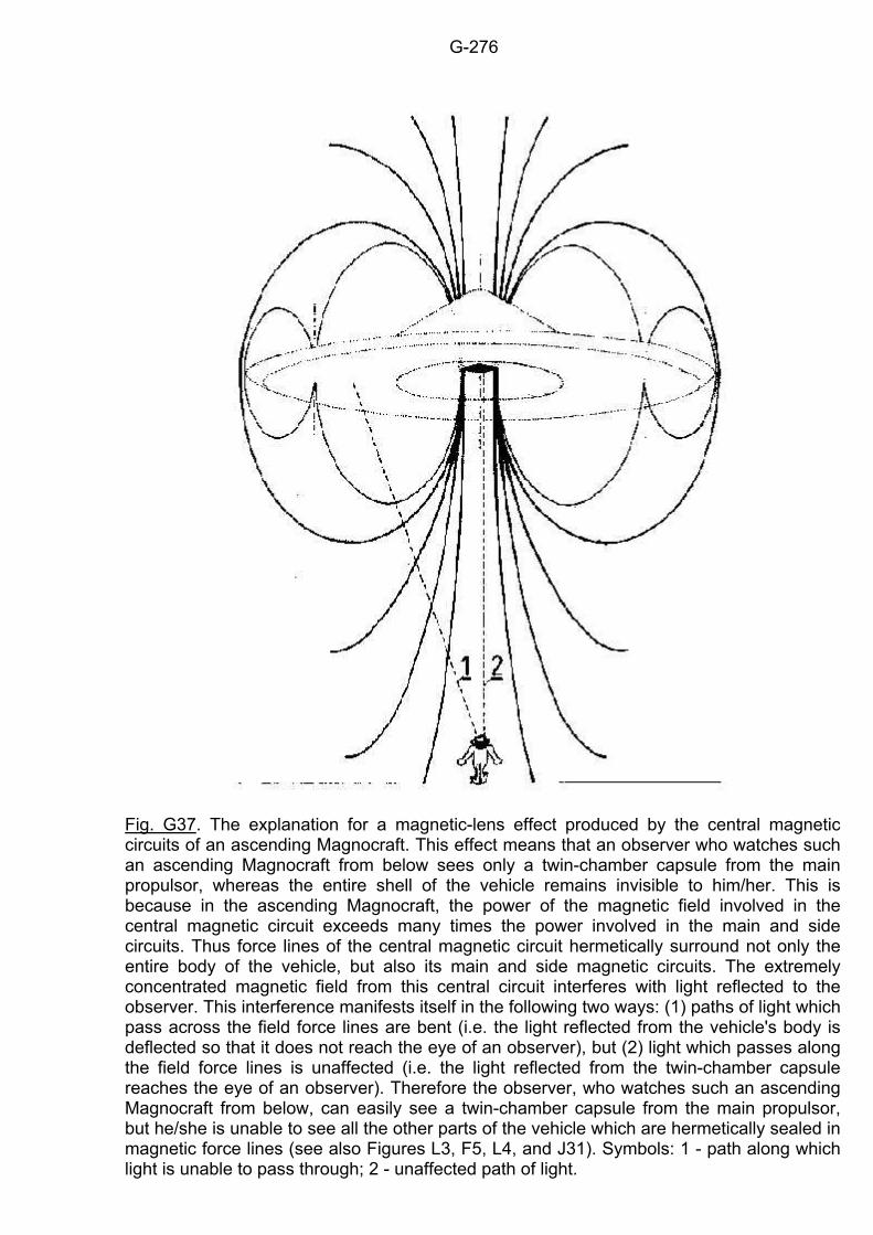
G-276
Fig. G37. The explanation for a magnetic-lens effect produced by the central magnetic circuits of an ascending Magnocraft. This effect means that an observer who watches such an ascending Magnocraft from below sees only a twin-chamber capsule from the main propulsor, whereas the entire shell of the vehicle remains invisible to him/her. This is because in the ascending Magnocraft, the power of the magnetic field involved in the central magnetic circuit exceeds many times the power involved in the main and side circuits. Thus force lines of the central magnetic circuit hermetically surround not only the entire body of the vehicle, but also its main and side magnetic circuits. The extremely concentrated magnetic field from this central circuit interferes with light reflected to the observer. This interference manifests itself in the following two ways: (1) paths of light which pass across the field force lines are bent (i.e. the light reflected from the vehicle's body is deflected so that it does not reach the eye of an observer), but (2) light which passes along the field force lines is unaffected (i.e. the light reflected from the twin-chamber capsule reaches the eye of an observer). Therefore the observer, who watches such an ascending Magnocraft from below, can easily see a twin-chamber capsule from the main propulsor, but he/she is unable to see all the other parts of the vehicle which are hermetically sealed in magnetic force lines (see also Figures L3, F5, L4, and J31). Symbols: 1 - path along which light is unable to pass through; 2 - unaffected path of light.
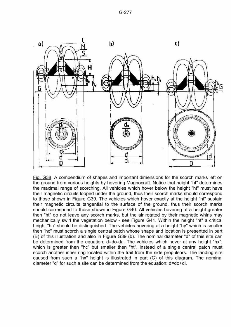
G-277
Fig. G38. A compendium of shapes and important dimensions for the scorch marks left on the ground from various heights by hovering Magnocraft. Notice that height "ht" determines the maximal range of scorching. All vehicles which hover below the height "ht" must have their magnetic circuits looped under the ground, thus their scorch marks should correspond to those shown in Figure G39. The vehicles which hover exactly at the height "ht" sustain their magnetic circuits tangential to the surface of the ground, thus their scorch marks should correspond to those shown in Figure G40. All vehicles hovering at a height greater then "ht" do not leave any scorch marks, but the air rotated by their magnetic whirls may mechanically swirl the vegetation below - see Figure G41. Within the height "ht" a critical height "hc" should be distinguished. The vehicles hovering at a height "hy" which is smaller then "hc" must scorch a single central patch whose shape and location is presented in part (B) of this illustration and also in Figure G39 (b). The nominal diameter "d" of this site can be determined from the equation: d=do-da. The vehicles which hover at any height "hx", which is greater then "hc" but smaller then "ht", instead of a single central patch must scorch another inner ring located within the trail from the side propulsors. The landing site caused from such a "hx" height is illustrated in part (C) of this diagram. The nominal diameter "d" for such a site can be determined from the equation: d=do+di.
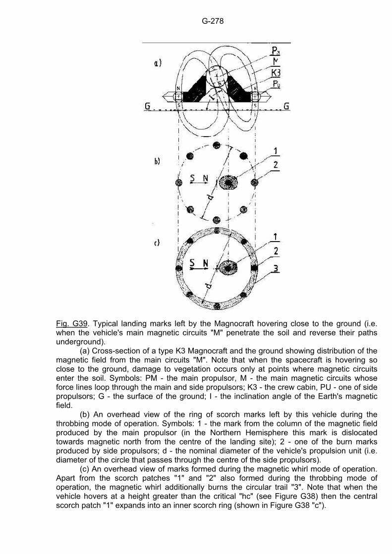
G-278
Fig. G39. Typical landing marks left by the Magnocraft hovering close to the ground (i.e. when the vehicle's main magnetic circuits "M" penetrate the soil and reverse their paths underground). (a) Cross-section of a type K3 Magnocraft and the ground showing distribution of the magnetic field from the main circuits "M". Note that when the spacecraft is hovering so close to the ground, damage to vegetation occurs only at points where magnetic circuits enter the soil. Symbols: PM - the main propulsor, M - the main magnetic circuits whose force lines loop through the main and side propulsors; K3 - the crew cabin, PU - one of side propulsors; G - the surface of the ground; I - the inclination angle of the Earth's magnetic field. (b) An overhead view of the ring of scorch marks left by this vehicle during the throbbing mode of operation. Symbols: 1 - the mark from the column of the magnetic field produced by the main propulsor (in the Northern Hemisphere this mark is dislocated towards magnetic north from the centre of the landing site); 2 - one of the burn marks produced by side propulsors; d - the nominal diameter of the vehicle's propulsion unit (i.e. diameter of the circle that passes through the centre of the side propulsors). (c) An overhead view of marks formed during the magnetic whirl mode of operation. Apart from the scorch patches "1" and "2" also formed during the throbbing mode of operation, the magnetic whirl additionally burns the circular trail "3". Note that when the vehicle hovers at a height greater than the critical "hc" (see Figure G38) then the central scorch patch "1" expands into an inner scorch ring (shown in Figure G38 "c").
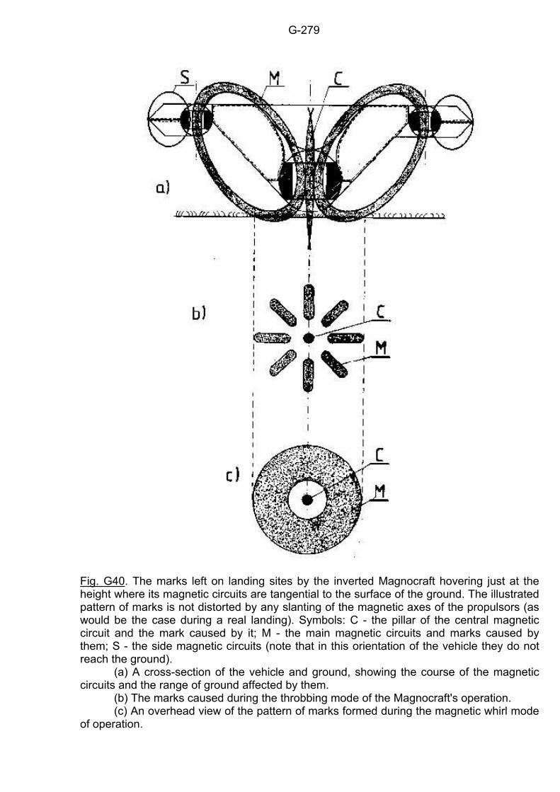
G-279
Fig. G40. The marks left on landing sites by the inverted Magnocraft hovering just at the height where its magnetic circuits are tangential to the surface of the ground. The illustrated pattern of marks is not distorted by any slanting of the magnetic axes of the propulsors (as would be the case during a real landing). Symbols: C - the pillar of the central magnetic circuit and the mark caused by it; M - the main magnetic circuits and marks caused by them; S - the side magnetic circuits (note that in this orientation of the vehicle they do not reach the ground). (a) A cross-section of the vehicle and ground, showing the course of the magnetic circuits and the range of ground affected by them. (b) The marks caused during the throbbing mode of the Magnocraft's operation. (c) An overhead view of the pattern of marks formed during the magnetic whirl mode of operation.
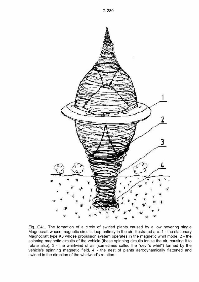
G-280
Fig. G41. The formation of a circle of swirled plants caused by a low hovering single Magnocraft whose magnetic circuits loop entirely in the air. Illustrated are: 1 - the stationary Magnocraft type K3 whose propulsion system operates in the magnetic whirl mode, 2 - the spinning magnetic circuits of the vehicle (these spinning circuits ionize the air, causing it to rotate also), 3 - the whirlwind of air (sometimes called the "devil's whirl") formed by the vehicle's spinning magnetic field, 4 - the nest of plants aerodynamically flattened and swirled in the direction of the whirlwind's rotation.
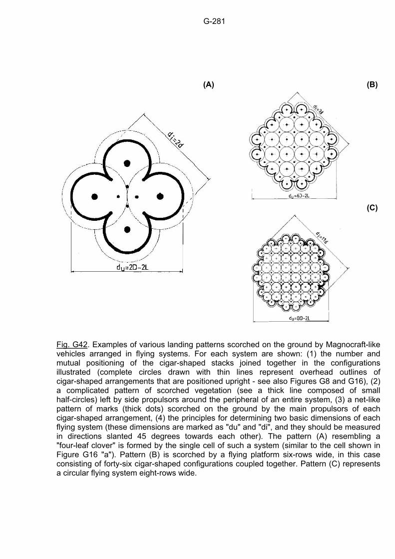
G-281
(B)
(A)
(C)
Fig. G42. Examples of various landing patterns scorched on the ground by Magnocraft-like vehicles arranged in flying systems. For each system are shown: (1) the number and mutual positioning of the cigar-shaped stacks joined together in the configurations illustrated (complete circles drawn with thin lines represent overhead outlines of cigar-shaped arrangements that are positioned upright - see also Figures G8 and G16), (2) a complicated pattern of scorched vegetation (see a thick line composed of small half-circles) left by side propulsors around the peripheral of an entire system, (3) a net-like pattern of marks (thick dots) scorched on the ground by the main propulsors of each cigar-shaped arrangement, (4) the principles for determining two basic dimensions of each flying system (these dimensions are marked as "du" and "di", and they should be measured in directions slanted 45 degrees towards each other). The pattern (A) resembling a "four-leaf clover" is formed by the single cell of such a system (similar to the cell shown in Figure G16 "a"). Pattern (B) is scorched by a flying platform six-rows wide, in this case consisting of forty-six cigar-shaped configurations coupled together. Pattern (C) represents a circular flying system eight-rows wide.
H-282
Chapter H:
PERSONAL PROPULSION The Magnocraft utilizes only one of a number of propulsion units which can be formed by a combination of magnetic propulsors. A unit entirely different from that of the Magnocraft, but whose applications are as equally wide ranging as those of the Magnocraft itself, is shown in Figure H1. The main characteristic of this new unit is that its framework creates a human-shaped structure. For this reason it is called "magnetic personal propulsion". The propulsion based on this new unit can be applied to cause the displacement of a person in space without using any vehicle, or to enhance the ways this person normally moves. Similarly as is the case with the Magnocraft, the personal propulsion also contains a set of eight side propulsors (marked U, V, W, and X) and a set of two main propulsors (in Figure H1 marked ML, MR). Both these sets are connected by the body of the user into one effective propulsion system. The body performs the function of a "carrying structure" or a framework. Each propulsor from both sets contains a single twin-chamber capsule, only a few millimeters in size, which is assembled inside of a spherical casing. The casing and its capsule are similar to that used in the Magnocraft (see Figure G1), only they are drastically miniaturized. Each of the twin-chamber capsules is composed of two small Oscillatory Chambers inserted one inside the other, as was described in subsection F6.1. The operation of Oscillatory Chambers allows for their miniaturization to the size of only a few millimeters, without any significant decrease in their output. Therefore, the propulsors of the personal propulsion system can be built small enough to allow for their assembly into articles of human apparel (i.e. belts and shoes) without causing any noticeable discomfort or change in the size and weight of these articles. On the other hand, these propulsors which are almost unnoticeable, will provide their wearer with the ability to fly in the air or space with a speed limited only by the performance of physiological functions (especially breathing), with enormous physical strength, with invisibility, and with protection from the action of any weapon that could be used against him/her. H1. The standard garment of personal propulsion The standard garment of personal propulsion is shown in Figure H2. This garment includes a number of special components. Shoes (1) contain miniature magnetic propulsors built into the soles. These are called "main propulsors". Apart from this, the personal propulsion garment uses another eight miniaturized propulsors assembled into a segmented belt (2). These are called "side" propulsors. The garment also includes a kind of magnetoreflective "skin". This "skin" consists of a one-piece costume (3) with a protective hood (5), and gloves (4). These are worn to prevent the magnetic field from looping through the person's body. The hood (5) and gloves (4) are so designed that they hermetically join with the costume (3), thus forming a single-piece garment. Each part of the garment's "skin" is made of a magnetoreflective material, which cannot be penetrated by a magnetic field, so that it protects the body from the destructive action of a strong, pulsating magnetic field. Even though the face remains uncovered, the magnetic field cannot penetrate the brain because the design of the hood makes the looping of the force lines impossible. A graphite-based cream can be used to additionally protect the facial skin. (It was discovered that graphite is the best natural magnetoreflective material.) But this cream which stops the magnetic field from acting, also gives the face a strange colouring.
H-283
The special gloves (4) complementing the magnetic personal propulsion are so designed that they not only protect the fingers from the magnetic field, but also from electric charges. These charges are a by-product of the propulsors' operation. The pulsating magnetic field generated by the side propulsors (2) induces a strong electrical field around the person's hip. Charges from this field accumulate at the tips of the person's fingers. The forces of relative repulsion from these charges part the fingers (similar to the way they do with the foils of an electroscope). This action is too weak to cause bodily injury, but after a length of time could cause a painful racking of the skin and muscles. The web-like connectors between the fingers of the gloves protect the wearer from these unpleasant effects. When the wearer of this costume is required to do heavy physical work, he/she wears two additional enhancement propulsors, which are placed on the joints of the wrists similar to our wrist watches - see Figure H3 (b). These propulsors, by co-operation with the magnetic framework created by the other propulsors, give unusual strength to his/her hand movements. Therefore, a person so equipped is able to lift loads weighing several tons, remove strong structures, tear trees out by the roots, and so on. H2. A special version of personal propulsion with cushions around the hips The standard garment of personal propulsion described in the previous subsection can be subjected to two modifications, producing some useful operational attributes. The first such modification of the standard garment is shown in Figure H3 (a). In this version, the wearer's palms are shielded from the action of a strong field by a protective screen. Therefore it allows for the elimination of gloves. This enables the hands to perform precisely (e.g. to assemble a very precise device under water) without the necessity for switching off the action of the propulsors. In this first modification of the garment, the special protective cushions (1) are joined around the eight-segmented belt (3). These are filled with helium, the gas which has the highest resistance to ionization (or ionization electric potential). The inner surface of the outside cover of these cushions has a magnetoreflective screen (2). Because of this, the field yield of the belt cannot act on the hands as strongly as in the standard version of the garment, so they do not need to be protected with gloves. The cushions (1) are divided by partitions (4) into eight separate chambers. Each propulsor from the belt (3) is housed in such a separate chamber. This makes it impossible to create a plasma whirl which would follow the magnetic whirl produced by the propulsors in the belt. Therefore there is no danger of the person's hands being burnt. This costume, which has the helium cushions, looks strange as it is thicker around the person's hips. Part (a) of Figure H3 shows also an alternative protection of the user's head. In this protection the transparent and magnetically impenetrable helmet (5) replaces the hood and the graphite cream described with the standard version of personal propulsion. It should be stressed that such a helmet can be used with every version of personal propulsion, not only with the one discussed in this subsection. H3. The garment with the main propulsors in epaulets In both versions of the personal propulsion described above, the main propulsors were built into the soles of shoes. Such a solution displays, however, a serious drawback, which is the set of two forces "B" see part (b) of Figure H4. These forces, acting between the legs, cause legs to stay apart. In effect, the movements of the wearer of this propulsion are not completely free and convenient. To eliminate these forces "B", another version of personal propulsion will be built, which is shown in Figure H3 (b). In this version the main propulsors are removed from the soles of the shoes and placed in the epaulets (1) of the user. From the operational point of
H-284
view such a change of position does not introduce any difference in the effectiveness of the propulsion. But for the user it means freedom of leg movements. Therefore the version of personal propulsion presented here can be applied in every situation requiring the use of the legs. Its drawback is the closeness of the head to the sources of a strong magnetic field (i.e. to both main propulsors). Therefore the face and head must be protected particularly carefully. In the case where there is a danger of the layer of protective cream being torn from the face (i.e. as the effect of work being performed), the user needs to wear a special mask on his/her face (similar to the mask used by the "spiderman" and "superheroes" in American movies, or to the type favoured by bank robbers). Because of the impression of widening the user's shoulders by the main propulsors placed within the epaulets, this version of personal propulsion gives its wearer a distinct triangular appearance. H4. Principles of operation of magnetic personal propulsion The principles of operation of magnetic personal propulsion are illustrated in Figure H4. Part (a) shows eight side propulsors which are assembled into the belt, and which are oriented so as to repel the Earth's magnetic field. By this they create a lifting force "R" which carries the wearer. The miniature main propulsors in the soles of the shoes are oriented towards the attraction with the environmental magnetic field. Thus they produce stabilization forces "A" which determine the position required by the person during flight. Both forces "R" and "A" are produced by the Earth's magnetic field interacting with the field generated by the main and side propulsors. So the product of this group of interactions can be called the "outside" forces. Apart from these, the personal propulsion produces another type of interaction, which can be called "inside" forces. These are formed by the relative interactions between the subsequent propulsors themselves. The "inside" forces are shown in Figure H4 (b). They include: 1. The forces "B" of relative repulsion occurring between both of the main propulsors from the soles of the shoes. The repulsive forces "B" are created because the magnetic poles of both these propulsors are oriented in the same direction. 2. The forces "E" of relative repulsion between each of the eight side propulsors from the belt. 3. The forces "Q" of relative attraction between each main propulsor from the shoes and each side propulsor from the belt. These attraction forces "Q" are created because the magnetic poles of the two main propulsors are oriented in opposition to the poles of all of the side propulsors. Note that there is a close correlation between the sets of "outside" and "inside" forces formed in the personal propulsion, and the similar forces formed in the structure of the Magnocraft - see Figure G20 and subsection G4.2. The presence of the outside and inside forces benefit the person because they join the separate elements of the propulsion into one solid system. The operation of this system is so determined that opposing forces are relatively balanced. For example, when the carrying "R" and stabilizing "A" forces tense the wearer, simultaneously the forces "Q" appear which compress his/her body along the same direction. This system of mutually balanced forces creates a "magnetic framework" which holds and carries the person in a way identical to that of the Magnocraft. There is a special condition for the balancing of the repulsive forces "B" acting between the legs. This requires that the legs must be kept apart at all times when the personal propulsion is used. This gives the body a stance that is very distinctive for wearers of personal propulsion. Their legs must be kept apart not only during all flights, but also when aiding the usual manner of moving, such as walking, swimming, etc. To control the personal propulsion specially adjusted micro-computers are used. These computers read bio-currents from the back of the neck and transform them into control signals. So just to think of moving up, sideways or downwards causes instant achievement of the desired displacement, which is obtained without any movement from the
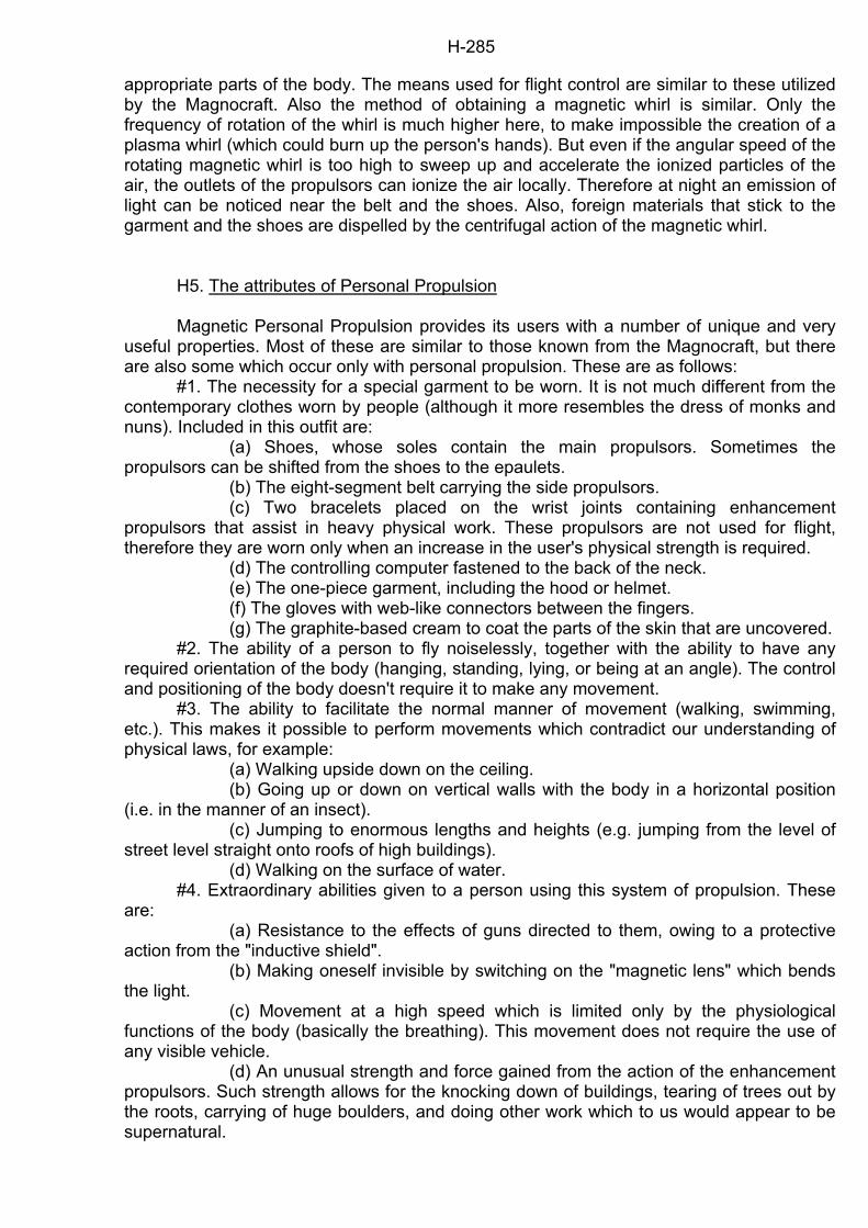
H-285
appropriate parts of the body. The means used for flight control are similar to these utilized by the Magnocraft. Also the method of obtaining a magnetic whirl is similar. Only the frequency of rotation of the whirl is much higher here, to make impossible the creation of a plasma whirl (which could burn up the person's hands). But even if the angular speed of the rotating magnetic whirl is too high to sweep up and accelerate the ionized particles of the air, the outlets of the propulsors can ionize the air locally. Therefore at night an emission of light can be noticed near the belt and the shoes. Also, foreign materials that stick to the garment and the shoes are dispelled by the centrifugal action of the magnetic whirl. H5. The attributes of Personal Propulsion Magnetic Personal Propulsion provides its users with a number of unique and very useful properties. Most of these are similar to those known from the Magnocraft, but there are also some which occur only with personal propulsion. These are as follows: #1. The necessity for a special garment to be worn. It is not much different from the contemporary clothes worn by people (although it more resembles the dress of monks and nuns). Included in this outfit are: (a) Shoes, whose soles contain the main propulsors. Sometimes the propulsors can be shifted from the shoes to the epaulets. (b) The eight-segment belt carrying the side propulsors. (c) Two bracelets placed on the wrist joints containing enhancement propulsors that assist in heavy physical work. These propulsors are not used for flight, therefore they are worn only when an increase in the user's physical strength is required. (d) The controlling computer fastened to the back of the neck. (e) The one-piece garment, including the hood or helmet. (f) The gloves with web-like connectors between the fingers. (g) The graphite-based cream to coat the parts of the skin that are uncovered. #2. The ability of a person to fly noiselessly, together with the ability to have any required orientation of the body (hanging, standing, lying, or being at an angle). The control and positioning of the body doesn't require it to make any movement. #3. The ability to facilitate the normal manner of movement (walking, swimming, etc.). This makes it possible to perform movements which contradict our understanding of physical laws, for example: (a) Walking upside down on the ceiling. (b) Going up or down on vertical walls with the body in a horizontal position (i.e. in the manner of an insect). (c) Jumping to enormous lengths and heights (e.g. jumping from the level of street level straight onto roofs of high buildings). (d) Walking on the surface of water. #4. Extraordinary abilities given to a person using this system of propulsion. These are: (a) Resistance to the effects of guns directed to them, owing to a protective action from the "inductive shield". (b) Making oneself invisible by switching on the "magnetic lens" which bends the light. (c) Movement at a high speed which is limited only by the physiological functions of the body (basically the breathing). This movement does not require the use of any visible vehicle. (d) An unusual strength and force gained from the action of the enhancement propulsors. Such strength allows for the knocking down of buildings, tearing of trees out by the roots, carrying of huge boulders, and doing other work which to us would appear to be supernatural.

H-286
(e) A biological sterilization of the environment through the killing of micro-organisms that are in the range of the field (this sterilization in turn can trigger various biological consequences). #5. The need for the body to adopt a particular stance which is characterized by: the legs permanently set apart or bent into a squat position, the hands being forced away from the belt, the parting of the fingers, etc. Also, as a result of an electrical charge, all hair on the uncovered parts of the body can be standing on end. #6. The forcing of magnetic-borne changes in the surroundings, similar to those caused by the Magnocraft's propulsion. We can mention here especially: burn marks on surfaces underneath the shoes, firing away of objects which come close to the belt, the electrical charging of insulating materials (e.g. hair), ionizing of the air (which can cause a glow near the belt and shoes), production of an active ozone, the smell of which will accompany the propulsion's wearer (this smell can be confused with the smell of sulfur by those not accustomed to it), etc.
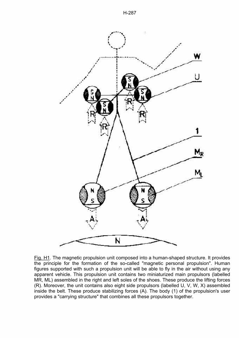
H-287
Fig. H1. The magnetic propulsion unit composed into a human-shaped structure. It provides the principle for the formation of the so-called "magnetic personal propulsion". Human figures supported with such a propulsion unit will be able to fly in the air without using any apparent vehicle. This propulsion unit contains two miniaturized main propulsors (labelled MR, ML) assembled in the right and left soles of the shoes. These produce the lifting forces (R). Moreover, the unit contains also eight side propulsors (labelled U, V, W, X) assembled inside the belt. These produce stabilizing forces (A). The body (1) of the propulsion's user provides a "carrying structure" that combines all these propulsors together.
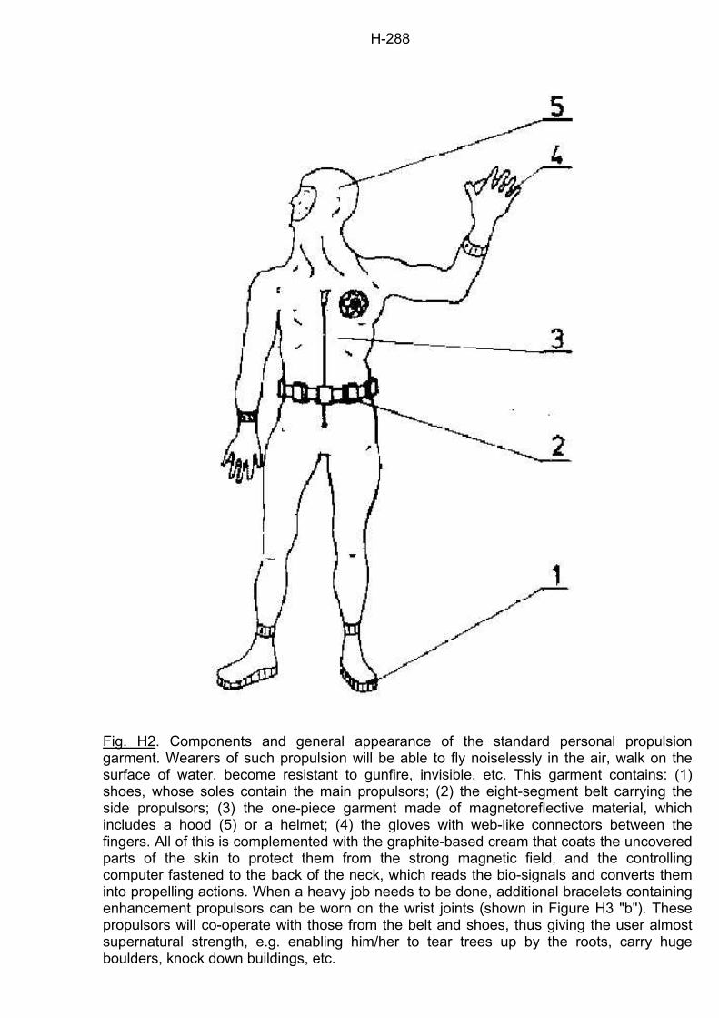
H-288
Fig. H2. Components and general appearance of the standard personal propulsion garment. Wearers of such propulsion will be able to fly noiselessly in the air, walk on the surface of water, become resistant to gunfire, invisible, etc. This garment contains: (1) shoes, whose soles contain the main propulsors; (2) the eight-segment belt carrying the side propulsors; (3) the one-piece garment made of magnetoreflective material, which includes a hood (5) or a helmet; (4) the gloves with web-like connectors between the fingers. All of this is complemented with the graphite-based cream that coats the uncovered parts of the skin to protect them from the strong magnetic field, and the controlling computer fastened to the back of the neck, which reads the bio-signals and converts them into propelling actions. When a heavy job needs to be done, additional bracelets containing enhancement propulsors can be worn on the wrist joints (shown in Figure H3 "b"). These propulsors will co-operate with those from the belt and shoes, thus giving the user almost supernatural strength, e.g. enabling him/her to tear trees up by the roots, carry huge boulders, knock down buildings, etc.
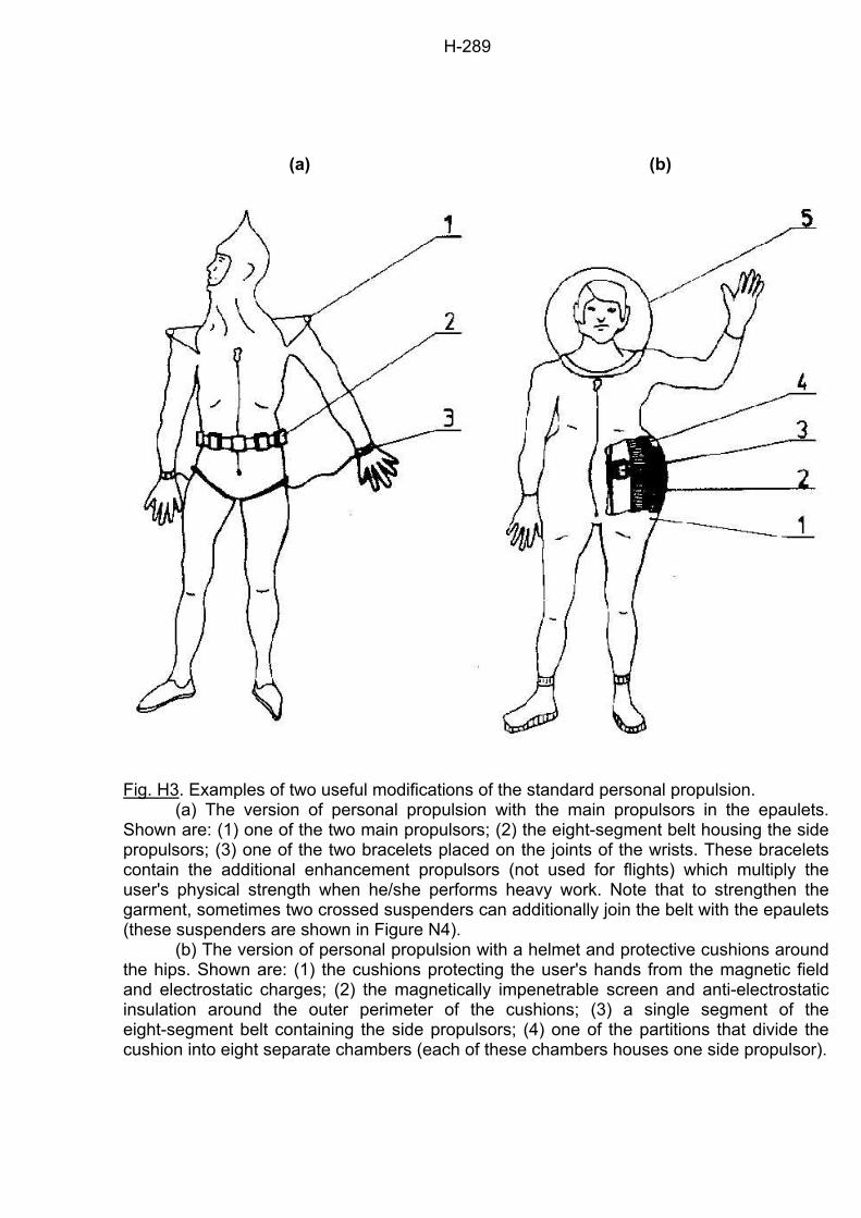
H-289
(a)
(b)
Fig. H3. Examples of two useful modifications of the standard personal propulsion. (a) The version of personal propulsion with the main propulsors in the epaulets. Shown are: (1) one of the two main propulsors; (2) the eight-segment belt housing the side propulsors; (3) one of the two bracelets placed on the joints of the wrists. These bracelets contain the additional enhancement propulsors (not used for flights) which multiply the user's physical strength when he/she performs heavy work. Note that to strengthen the garment, sometimes two crossed suspenders can additionally join the belt with the epaulets (these suspenders are shown in Figure N4). (b) The version of personal propulsion with a helmet and protective cushions around the hips. Shown are: (1) the cushions protecting the user's hands from the magnetic field and electrostatic charges; (2) the magnetically impenetrable screen and anti-electrostatic insulation around the outer perimeter of the cushions; (3) a single segment of the eight-segment belt containing the side propulsors; (4) one of the partitions that divide the cushion into eight separate chambers (each of these chambers houses one side propulsor).
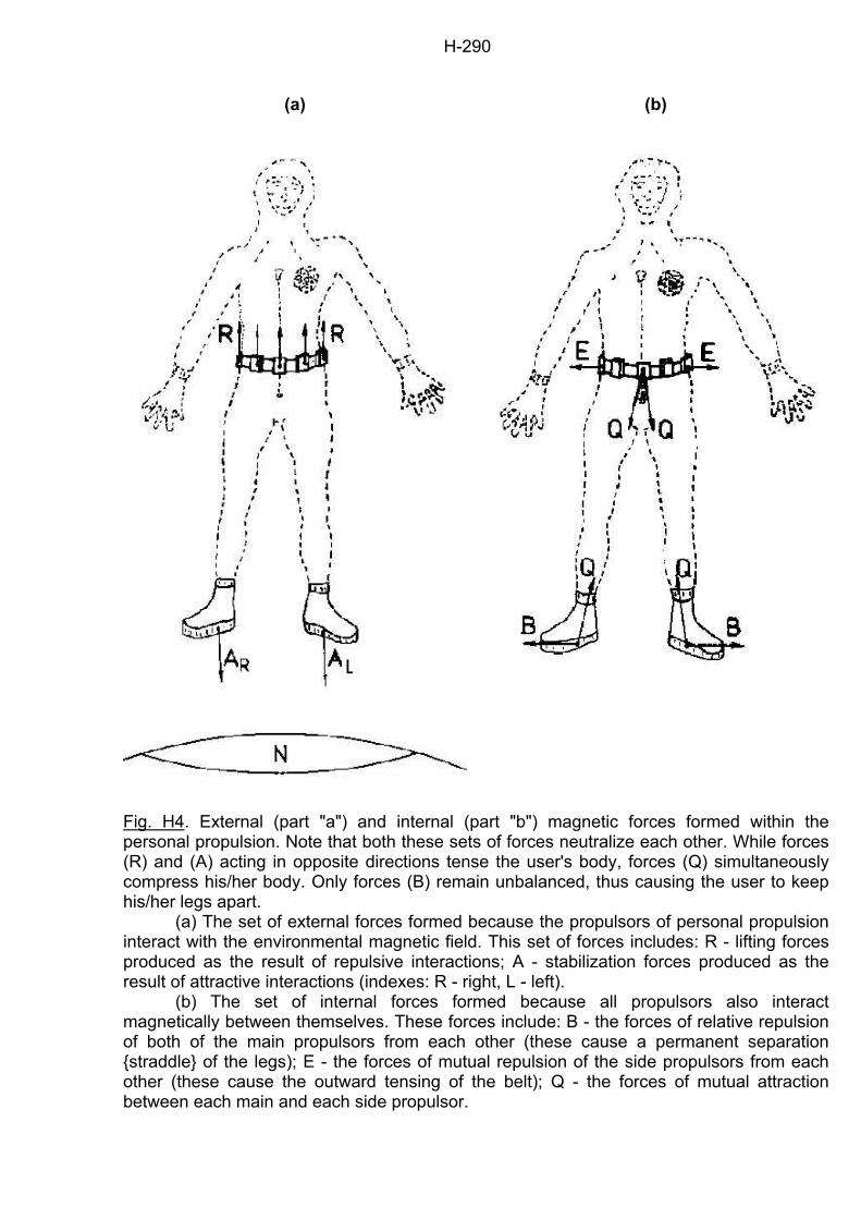
H-290
(a)
(b)
Fig. H4. External (part "a") and internal (part "b") magnetic forces formed within the personal propulsion. Note that both these sets of forces neutralize each other. While forces (R) and (A) acting in opposite directions tense the user's body, forces (Q) simultaneously compress his/her body. Only forces (B) remain unbalanced, thus causing the user to keep his/her legs apart. (a) The set of external forces formed because the propulsors of personal propulsion interact with the environmental magnetic field. This set of forces includes: R - lifting forces produced as the result of repulsive interactions; A - stabilization forces produced as the result of attractive interactions (indexes: R - right, L - left). (b) The set of internal forces formed because all propulsors also interact magnetically between themselves. These forces include: B - the forces of relative repulsion of both of the main propulsors from each other (these cause a permanent separation straddle of the legs); E - the forces of mutual repulsion of the side propulsors from each other (these cause the outward tensing of the belt); Q - the forces of mutual attraction between each main and each side propulsor.
I-291
Chapter I:
THE FOUR-PROPULSOR SPACECRAFT The Four-Propulsor Spacecraft, together with the Magnocraft and Personal Propulsion, represents the third basic application of magnetic propulsors. While the operation of the first two propulsion systems was based on the so-called "twin-chamber capsule", this third basic spacecraft utilizes the unique properties of a different arrangement of Oscillatory Chambers, called the "spider configuration" - see subsection F6.2. Each propulsor of the Four-Propulsor Spacecraft consists of one such spider configuration. A magnetic field produced by this configuration displays all the attributes required for flight and for manoeuvring a vehicle. This is the reason why the Four-Propulsor Spacecraft can limit its entire propulsion system to four propulsors only. Because the number of propulsors is the most unique feature of this spacecraft, its name incorporates this number. Each of its propulsors is attached to the crew cabin. Thus, the four barrel-shaped propulsors protruding outside the main body of the spacecraft also form an identifying feature very characteristic of this type of vehicle. An important attribute of the Four-Propulsor Spacecraft is that its living compartment, containing crew cabin and cargo space, may take any shape. Therefore this vehicle will be built in the various geometrical forms which best fit the shape of the cargo being carried inside, or which is most convenient to the comfort of people traveling within it. I1. The general design of the Four-Propulsor Spacecraft The general design of the Four-Propulsor Spacecraft is shown in Figure I1. The main body of this vehicle is formed from its living compartment (2). This compartment has a general shape of a cubical or rectangular hut. On its top a gable roof (1) is attached which adds aerodynamic properties to the vehicle, and which also allows for the recognition of its type at a distance. At all four corners of the living compartment individual, barrel-shaped or jug-shaped propulsors (3) are placed. Each of these propulsors produces its own column of a spinning magnetic field, whose core is marked as (4) in Figure I1. Within each column, a dark core (4) and lighter crust (5) can be distinguished. The core (4) is formed because the output of the main Oscillatory Chamber (marked M in Figure I2) of the propulsor's spider configuration spins around its own magnetic axis "m". But the crust (5) is formed because the four columns of magnetic field produced by the side Oscillatory Chambers (marked U, V, W and X) rotate at some distance from the magnetic axis "m". The appearance of these two parts of the field's columns make them appear as spinning black drills. (These drills bear some resemblance to helicopter blades, except that they are quite narrow and long instead of wide and short. Therefore, some amateur witnesses may occasionally confuse the Four-Propulsor Spacecraft with a multiple-rotor helicopter.) The living compartment (2) is hermetically covered by a shell made of material impenetrable by the magnetic field (i.e. magnetoreflective). Therefore its interior is screened from any dangerous action of a strong field, and may contain the crew cabin, passenger decks, cargo holds, instruments, equipment utilities, etc. The shape of the living compartment takes a geometrical form best suiting the comfort of crew and passengers or well adapted to the shape of cargo carried inside. Usually it will be hut-like or cubicle in shape, but on special occasions many other forms can be used, for example spherical, rocket-like, or cone-like (because these other shapes will be used rather rarely, an illustration of their characteristics is not provided here). The walls of the living compartment are made of a mirror-like transparent material, whose degree of transparency and light reflectiveness can be regulated by the crew (i.e. during flights at night the crew
I-292
can make these walls completely transparent, whereas during flights near the Sun they can transform the walls, making them completely reflective so that inside the spaceship a pleasant shade can prevail). Therefore there will be no need to provide the vehicle with windows. However, to enable crew and passengers to go into (and from) the deck, the Four-Propulsor Spacecraft must contain a door. I2. The operation of the Four-Propulsor Spacecraft The operation of the Four-Propulsor Spacecraft is slightly different from the operation of both of the magnetic propulsion systems presented previously, i.e. from the discoidal Magnocraft and Personal Propulsion System. But this operation is also quite similar. In the Four-Propulsor Spacecraft, each of its four propulsors forms a kind of miniature Magnocraft. This means that each of its propulsors is capable of independent flight and manoeuvring. Therefore the living compartment of the Four-Propulsor Spacecraft is carried by something like four independent, miniature Magnocraft, flying on parallel paths, each of them joined to the main body. Every propulsor produces its own column of magnetic field, and during landing it can make its own scorch mark on the ground. The general design of a propulsor for the Four-Propulsor Spacecraft is shown in Figure I2. It consists of five Oscillatory Chambers arranged together into the "spider configuration" and covered with a magnetically penetrable shell. The propulsor's shell can take either the shape of a barrel see (1) in part (a) of Figure I2 or the shape of a jug see (2) in part (b) of Figure I2. The propulsor's spider configuration is composed of the main Oscillatory Chamber (M) which is surrounded by four side chambers (U, V, W, and X). Such an arrangement of chambers gives to each propulsor of the Four-Propulsor Spacecraft all the attributes that previously were provided by the entire propulsion unit of the Magnocraft - compare subsections F6.2 and G1.2. It is able to produce a spinning magnetic field, all of whose parameters are strictly controlled. Therefore even when acting in isolation from the rest of the spacecraft, this configuration would be able to fully control its flight and maneuvers. Thus, the flying of the Four-Propulsor Spacecraft depends mainly on an appropriate co-ordination of the actions of all four propulsors, so that the total effect is to pull the spacecraft in the desired direction. The propulsors of the Four-Propulsor Spacecraft produce two kinds of magnetic whirls. Each propulsor produces a local magnetic whirl which involves its own output spinning around its own axis "m". In Figure I1 these four local whirls are marked as spinning columns (4) of magnetic field. Simultaneously all four propulsors co-operate in producing a resultant magnetic whirl that circulates around the entire crew cabin. But this resultant whirl is not so efficient as the one formed by the Magnocraft. An entirely different principle is employed in its creation (i.e. buoyancy instead of rotation of the magnetic circuits), and also it rotates around a different path. Thus, the resultant whirl just suffices to create an inductive shield that protects the Four-Propulsor Spacecraft from material objects directed at it, but it is insufficient to produce an effective vacuum bubble. All propulsors in the Four-Propulsor Spacecraft produce a very high magnetic output. At the same time, the like-poles of these propulsors are oriented in the same direction. Therefore, if their output was non-spinning, they would repel one another with an enormously powerful force. However, because their output spins, they create the relativistic phenomenon described below, which significantly reduces the forces of this reciprocal repulsion. Moreover, the magneto-dynamic effect described previously under the name of the magnetic equivalent of the "Magnus Effect" (see subsection G6.3.2) produces forces acting in the opposite directions, and therefore further neutralizing the repulsive interactions among propulsors. In this way, the force stability of the Four-Propulsor Spacecraft is achieved in a dynamic manner. To maintain this stability, the output from the spacecraft's propulsors must always be spinning. For this reason, the basic requirement of the mutual neutralization of inter-propulsor interactions explained above is that the magnetic field produced by each propulsor must spin all the time, even when the vehicle is motionless.
I-293
The relativistic phenomenon employed in neutralization of interactions between propulsors of the Four-Propulsor Spacecraft is quite well known amongst experts in magnetism. It depends on extending the effective length of a bar magnet as the result of a very fast spinning of its force lines around the magnet's central axis - see subsection G5.3. If the force lines spin fast enough around the magnet's central axis, their curvature contracts, and as a result the flux is limited to an area just around the magnet. This transforms a short bar magnet so that it acts like a very long thin one. Of course, it is not possible to mechanically spin a magnet fast enough to obtain the desired results. But the spider configuration simulates such a spinning through the forming from the subsequent outputs of its four side Oscillatory Chambers of a rotating magnetic wave similar to the wave produced by the side propulsors of the Magnocraft (see explanation in subsections G7.2 and F6.2). This wave spins around the propulsor's main magnetic axis "m". It can reach any desired angular velocity, causing the formation of the relativistic phenomenon which keeps the Four-Propulsor Spacecraft stable. I3. The properties of the Four-Propulsor Spacecraft The differences in the operation of the Four-Propulsor Spacecraft, in comparison to the operation of the Magnocraft, also cause differences in the properties of these vehicles. In general, the Four-Propulsor Spacecraft is not able to create an effective vacuum bubble around its surface (see subsection G9.1). Therefore all properties connected with the existence of the protective vacuum bubble do not apply to this vehicle. For example its flights are accompanied by friction with the atmosphere and by the sound effects produced from such friction (e.g. by a loud bang after passing the sound barrier). Therefore the vehicle's speed in the atmosphere will also be limited by the heat barrier. However, in free space, its speed may still be close to the speed of light. The absence of a vacuum bubble protecting this spacecraft will also make its flights through solid matter impossible (e.g. in rocks). The manoeuvrability of the Four-Propulsor Spacecraft will be on the same level as the manoeuvrability of the Magnocraft. But its ionic picture will have quite a different shape and features. During the ascent of this vehicle the picture will contain four very distinctive columns of ionized air, placed around the perimeter of the resultant magnetic whirl that surrounds the spacecraft's shape (e.g. a gable-roofed hut). This hut-shaped (resultant) whirl will be much less intensive than the four local whirls produced by the propulsors. During the descent of the Four-Propulsor Spacecraft, the local whirls from its propulsors can diminish, thus only a resultant hut-shaped whirl may remain visible. A number of Four-Propulsor Spacecraft are able to couple with one another into several configurations known from the Magnocraft. Two or more of these vehicles can join together forming an equivalent of the cigar-shaped flying complex (see Figure G8) or an equivalent of the spherical flying complex (see Figure G7). Also, the set of flying cigars formed in this way may join further into a higher ranking arrangement, representing an equivalent to the flying system of the Magnocraft (see Figure G16). The Four-Propulsor Spacecraft may also form configurations with the discoidal Magnocraft. In these configurations the spacecraft clings to the Magnocraft in such a way that the outlets from its four propulsors exactly align with the outlets of the Magnocraft's side propulsors. In order to enable such an alignment, the Four-Propulsor Spacecraft will only be built in such sizes which correspond to the sizes of the Magnocraft (i.e. which allow for the alignment of outlets from propulsors of both these vehicles). For this reason, eight separate types of the Four-Propulsor Spacecraft will also be distinguished. Their dimensions are provided in Table I1. The subsequent types of this spacecraft are marked as T2, T3, ..., and T9. Each of these types corresponds to an appropriate type of Magnocraft (e.g. type T2 of the Four-Propulsor Spacecraft corresponds to type K3 of the Magnocraft, T3 to K4, etc.). The long, thin columns of the spinning magnetic field produced by each propulsor will possess clearly defined boundaries. Therefore they will form a trap for the light, appearing
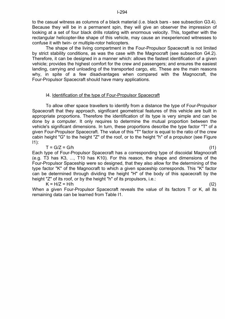
I-294
to the casual witness as columns of a black material (i.e. black bars - see subsection G3.4). Because they will be in a permanent spin, they will give an observer the impression of looking at a set of four black drills rotating with enormous velocity. This, together with the rectangular helicopter-like shape of this vehicle, may cause an inexperienced witnesses to confuse it with twin- or multiple-rotor helicopters. The shape of the living compartment in the Four-Propulsor Spacecraft is not limited by strict stability conditions, as was the case with the Magnocraft (see subsection G4.2). Therefore, it can be designed in a manner which: allows the fastest identification of a given vehicle; provides the highest comfort for the crew and passengers; and ensures the easiest landing, carrying and unloading of the transported cargo, etc. These are the main reasons why, in spite of a few disadvantages when compared with the Magnocraft, the Four-Propulsor Spacecraft should have many applications. I4. Identification of the type of Four-Propulsor Spacecraft To allow other space travellers to identify from a distance the type of Four-Propulsor Spacecraft that they approach, significant geometrical features of this vehicle are built in appropriate proportions. Therefore the identification of its type is very simple and can be done by a computer. It only requires to determine the mutual proportion between the vehicle's significant dimensions. In turn, these proportions describe the type factor "T" of a given Four-Propulsor Spacecraft. The value of this "T" factor is equal to the ratio of the crew cabin height "G" to the height "Z" of the roof, or to the height "h" of a propulsor (see Figure I1): T = G/Z = G/h (I1) Each type of Four-Propulsor Spacecraft has a corresponding type of discoidal Magnocraft (e.g. T3 has K3, ..., T10 has K10). For this reason, the shape and dimensions of the Four-Propulsor Spaceship were so designed, that they also allow for the determining of the type factor "K" of the Magnocraft to which a given spaceship corresponds. This "K" factor can be determined through dividing the height "H" of the body of this spacecraft by the height "Z" of its roof, or by the height "h" of its propulsors, i.e.: K = H/Z = H/h (I2) When a given Four-Propulsor Spacecraft reveals the value of its factors T or K, all its remaining data can be learned from Table I1.
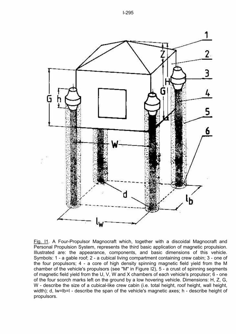
I-295
Fig. I1. A Four-Propulsor Magnocraft which, together with a discoidal Magnocraft and Personal Propulsion System, represents the third basic application of magnetic propulsion. Illustrated are: the appearance, components, and basic dimensions of this vehicle. Symbols: 1 - a gable roof; 2 - a cubical living compartment containing crew cabin; 3 - one of the four propulsors; 4 - a core of high density spinning magnetic field yield from the M chamber of the vehicle's propulsors (see "M" in Figure I2), 5 - a crust of spinning segments of magnetic field yield from the U, V, W and X chambers of each vehicle's propulsor; 6 - one of the four scorch marks left on the ground by a low hovering vehicle. Dimensions: H, Z, G, W - describe the size of a cubical-like crew cabin (i.e. total height, roof height, wall height, width); d, lw=lb=l - describe the span of the vehicle's magnetic axes; h - describe height of propulsors.
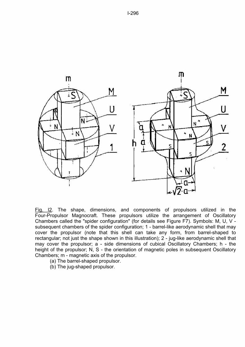
I-296
Fig. I2. The shape, dimensions, and components of propulsors utilized in the Four-Propulsor Magnocraft. These propulsors utilize the arrangement of Oscillatory Chambers called the "spider configuration" (for details see Figure F7). Symbols: M, U, V - subsequent chambers of the spider configuration; 1 - barrel-like aerodynamic shell that may cover the propulsor (note that this shell can take any form, from barrel-shaped to rectangular; not just the shape shown in this illustration); 2 - jug-like aerodynamic shell that may cover the propulsor; a - side dimensions of cubical Oscillatory Chambers; h - the height of the propulsor; N, S - the orientation of magnetic poles in subsequent Oscillatory Chambers; m - magnetic axis of the propulsor. (a) The barrel-shaped propulsor. (b) The jug-shaped propulsor.