Embed Size (px)
DESCRIPTION
Advanced Machining Processes
Citation preview

Manufacturing, Engineering & Technology, Fifth Edition, by Serope Kalpakjian and Steven R. Schmid.ISBN 0-13-148965-8. © 2006 Pearson Education, Inc., Upper Saddle River, NJ. All rights reserved.
Chapter 27Advanced Machining Processes

Manufacturing, Engineering & Technology, Fifth Edition, by Serope Kalpakjian and Steven R. Schmid.ISBN 0-13-148965-8. © 2006 Pearson Education, Inc., Upper Saddle River, NJ. All rights reserved.
Parts Made by Advanced Machining Processes
Figure 27.1 Examples of parts produced by advanced machining processes. (a)Samples of parts produced from waterjet cutting. (b) Turbine blade, produced byplunge EDM, in a fixture to produce the holes by EDM. Source: (a) Courtesy ofOmax Corporation. (b) Courtesy of Hi-TEK Mfg., Inc.
(a)(b)

Manufacturing, Engineering & Technology, Fifth Edition, by Serope Kalpakjian and Steven R. Schmid.ISBN 0-13-148965-8. © 2006 Pearson Education, Inc., Upper Saddle River, NJ. All rights reserved.
GeneralCharacteristicsof AdvancedMachiningProcesses
Manufacturing, Engineering & Technology, Fifth Edition, by Serope Kalpakjian and Steven R. Schmid.ISBN 0-13-148965-8. © 2006 Pearson Education, Inc., Upper Saddle River, NJ. All rights reserved.
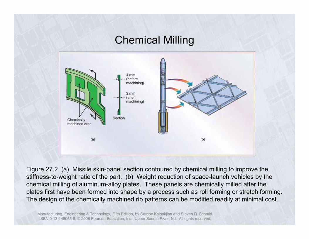
Chemical Milling
Figure 27.2 (a) Missile skin-panel section contoured by chemical milling to improve thestiffness-to-weight ratio of the part. (b) Weight reduction of space-launch vehicles by thechemical milling of aluminum-alloy plates. These panels are chemically milled after theplates first have been formed into shape by a process such as roll forming or stretch forming.The design of the chemically machined rib patterns can be modified readily at minimal cost.
Manufacturing, Engineering & Technology, Fifth Edition, by Serope Kalpakjian and Steven R. Schmid.ISBN 0-13-148965-8. © 2006 Pearson Education, Inc., Upper Saddle River, NJ. All rights reserved.
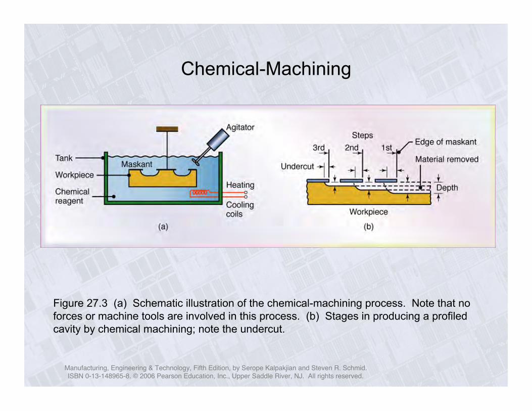
Chemical-Machining
Figure 27.3 (a) Schematic illustration of the chemical-machining process. Note that noforces or machine tools are involved in this process. (b) Stages in producing a profiledcavity by chemical machining; note the undercut.

Manufacturing, Engineering & Technology, Fifth Edition, by Serope Kalpakjian and Steven R. Schmid.ISBN 0-13-148965-8. © 2006 Pearson Education, Inc., Upper Saddle River, NJ. All rights reserved.
SurfaceRoughness
andTolerances
inMachining
Figure 27.4 Surface roughness and tolerances obtained in various machining processes. Notethe wide range within each process (see also Fig. 23.13). Source: Machining Data Handbook,3rd ed. Copyright © 1980. Used by permission of Metcut Research Associates, Inc.

Manufacturing, Engineering & Technology, Fifth Edition, by Serope Kalpakjian and Steven R. Schmid.ISBN 0-13-148965-8. © 2006 Pearson Education, Inc., Upper Saddle River, NJ. All rights reserved.
Parts Made by Chemical Blanking
Figure 27.5 Various parts made by chemical blanking. Note thefine detail. Source: Courtesy of Buckbee-Mears, St. Paul.

Manufacturing, Engineering & Technology, Fifth Edition, by Serope Kalpakjian and Steven R. Schmid.ISBN 0-13-148965-8. © 2006 Pearson Education, Inc., Upper Saddle River, NJ. All rights reserved.
Electrochemical Machining
Figure 27.6 Schematic illustration of the electrochemical machining process.

Manufacturing, Engineering & Technology, Fifth Edition, by Serope Kalpakjian and Steven R. Schmid.ISBN 0-13-148965-8. © 2006 Pearson Education, Inc., Upper Saddle River, NJ. All rights reserved.
Parts Made by Electrochemical Machining
Figure 27.7 Typical parts made by electrochemical machining. (a) Turbine blademade of nickel alloy of 360 HB. Note the shape of the electrode on the right. (b) Thinslots on a 4340-steel roller-bearing cage. (c) Integral airfoils on a compressor disk.

Manufacturing, Engineering & Technology, Fifth Edition, by Serope Kalpakjian and Steven R. Schmid.ISBN 0-13-148965-8. © 2006 Pearson Education, Inc., Upper Saddle River, NJ. All rights reserved.
Knee Implants
Figure 27.8 (a) Two total knee replacement systems showing metal implants(top pieces) with an ultra-high molecular-weight polyethylene insert (bottompieces). (b) Cross-section of the ECM process as applies to the metal implant.Source: Courtesy of Biomet, Inc.

Manufacturing, Engineering & Technology, Fifth Edition, by Serope Kalpakjian and Steven R. Schmid.ISBN 0-13-148965-8. © 2006 Pearson Education, Inc., Upper Saddle River, NJ. All rights reserved.
Electrochemical-Grinding Process
Figure 27.9 (a) Schematic illustration of the electrochemical-grinding process.(b) Thin slot produced on a round nickel-alloy tube by this process.

Manufacturing, Engineering & Technology, Fifth Edition, by Serope Kalpakjian and Steven R. Schmid.ISBN 0-13-148965-8. © 2006 Pearson Education, Inc., Upper Saddle River, NJ. All rights reserved.
Electrical-Discharge Machining Process
Figure 27.10 (a) Schematic illustration of the electrical-discharge machining process. This is one of themost widely used machining processes, particularly for die-sinking applications. (b) Examples of cavitiesproduced by the electrical-discharge machining process, using shaped electrodes. Two round parts (rear)are the set of dies for extruding the aluminum piece shown in front (see also Fig. 19.9b). (c) A spiral cavityproduced by EDM using a slowly rotating electrode similar to a screw thread. (d) Holes in a fuel-injectionnozzle made by EDM; the material is heat-treated steel. Source: (b) Courtesy of AGIE USA Ltd.

Manufacturing, Engineering & Technology, Fifth Edition, by Serope Kalpakjian and Steven R. Schmid.ISBN 0-13-148965-8. © 2006 Pearson Education, Inc., Upper Saddle River, NJ. All rights reserved.
Stepped Cavities Produced by EDM Process
Figure 27.11 Stepped cavities produced with a square electrode by the EDMprocess. The workpiece moves in the two principle horizontal directions (x – y), andits motion is synchronized with the downward movement of the electrode to producethese cavities. Also shown is a round electrode capable of producing round orelliptical cavities. Source: Courtesy of AGIE USA Ltd.

Manufacturing, Engineering & Technology, Fifth Edition, by Serope Kalpakjian and Steven R. Schmid.ISBN 0-13-148965-8. © 2006 Pearson Education, Inc., Upper Saddle River, NJ. All rights reserved.
The Wire EDM Process
Figure 27.12 Schematic illustration of thewire EDM process. As many as 50 hours ofmachining can be performed with one reel ofwire, which is then discarded.
!
Metal removal rate :
MRR = 4 "104ITw
#1.23
where
I = current in amperes
Tw = melting temperature of workpiece, °C

Manufacturing, Engineering & Technology, Fifth Edition, by Serope Kalpakjian and Steven R. Schmid.ISBN 0-13-148965-8. © 2006 Pearson Education, Inc., Upper Saddle River, NJ. All rights reserved.
Wire EDM
(a) (b)
Figure 27.13 (a) Cutting a thick plate with wire EDM. (b) A computer-controlled wire EDM machine. Source: Courtesy of AGIE USA Ltd.

Manufacturing, Engineering & Technology, Fifth Edition, by Serope Kalpakjian and Steven R. Schmid.ISBN 0-13-148965-8. © 2006 Pearson Education, Inc., Upper Saddle River, NJ. All rights reserved.
Laser-BeamMachining (LBM)
Figure 27.14 (a) Schematicillustration of the laser-beammachining process. (b) and (c)Examples of holes produced innonmetallic parts by LBM. (d)Cutting sheet metal with a laserbeam. Source: (d) Courtesy ofRofin-Sinar, Inc.

Manufacturing, Engineering & Technology, Fifth Edition, by Serope Kalpakjian and Steven R. Schmid.ISBN 0-13-148965-8. © 2006 Pearson Education, Inc., Upper Saddle River, NJ. All rights reserved.
General Applications of Lasers in Manufacturing
Manufacturing, Engineering & Technology, Fifth Edition, by Serope Kalpakjian and Steven R. Schmid.ISBN 0-13-148965-8. © 2006 Pearson Education, Inc., Upper Saddle River, NJ. All rights reserved.
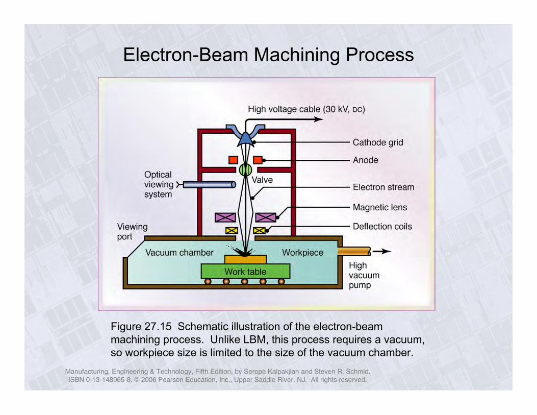
Electron-Beam Machining Process
Figure 27.15 Schematic illustration of the electron-beammachining process. Unlike LBM, this process requires a vacuum,so workpiece size is limited to the size of the vacuum chamber.

Manufacturing, Engineering & Technology, Fifth Edition, by Serope Kalpakjian and Steven R. Schmid.ISBN 0-13-148965-8. © 2006 Pearson Education, Inc., Upper Saddle River, NJ. All rights reserved.
Water-JetCuttingProcess
Figure 27.16 (a) Schematic illustration of the water-jet machining process. (b) Acomputer-controlled water-jet cutting machine cutting a granite plate. (c) Examples ofvarious nonmetallic parts produced by the water-jet cutting process. (Enlarged on nextslide). Source: Courtesy of Possis Corporation

Manufacturing, Engineering & Technology, Fifth Edition, by Serope Kalpakjian and Steven R. Schmid.ISBN 0-13-148965-8. © 2006 Pearson Education, Inc., Upper Saddle River, NJ. All rights reserved.
Nonmetallic Parts Made by Water-Jet Cutting
Enlargement of Fig. 27.16c. Examples of various nonmetallic parts produced bythe water-jet cutting process. Source: Courtesy of Possis Corporation

Manufacturing, Engineering & Technology, Fifth Edition, by Serope Kalpakjian and Steven R. Schmid.ISBN 0-13-148965-8. © 2006 Pearson Education, Inc., Upper Saddle River, NJ. All rights reserved.
Abrasive-Jet Machining
Figure 27.17 (a) Schematic illustration of the abrasive-jet machining process. (b)Examples of parts produced through abrasive-jet machining, produced in 50-mm (2-in.)thick 304 stainless steel. Source: Courtesy of OMAX Corporation.
(b)

Manufacturing, Engineering & Technology, Fifth Edition, by Serope Kalpakjian and Steven R. Schmid.ISBN 0-13-148965-8. © 2006 Pearson Education, Inc., Upper Saddle River, NJ. All rights reserved.
Case Study: Stent Manufacture
Figure 27.18 The Guidant MULTI-LINKTETRATM coronary stent system.
Figure 27.19 Detail of the 3-3-3MULTI-LINK TETRATM pattern.
Figure 27.20 Evolution ofthe stent surface. (a)MULTI-LINK TETRATM afterlasing. Note that a metalslug is still attached. (b)After removal of slag. (c)After electropolishing.