Embed Size (px)
Citation preview
Advanced Internet Technologies, SS 2004 1.1
Advanced Internet TechnologiesChapter 1
Introduction
Dr.-Ing. Falko Dressler
Chair for Computer Networks & InternetWilhelm-Schickard-Institute for Computer Science
University of Tübingen
http://net.informatik.uni-tuebingen.de/[email protected]
Advanced Internet Technologies, SS 2004 1.2
Falko Dressler
1990-1998: Study of Computer Science, University of Erlangen-Nuremberg, Germany
1998:M.Sc. in Computer Science (Dipl. Inf.), Department of Computer Science, University of Erlangen-Nuremberg, GermanyThesis Title: Monitoring of ATM Networks (Netzmonitoring auf ATM-Ebene)
1999-2003: Ph.D. studies of Computer Science, Department of Computer Science, University of Erlangen-Nuremberg, Germany
2003:Ph.D. in Computer Science (Dr.-Ing.), Department of Computer Science, University of Erlangen-Nuremberg, GermanyThesis Title: Monitoring of Multicast Networks for Time-Synchronous Communication
Since 2003: Senior Researcher (wiss. Assistent), Computer Networks and Internet, Wilhelm-Schickard-Institute for Computer Science, University of Tuebingen, Germany
Advanced Internet Technologies, SS 2004 1.3
Course organization
LectureThursday, 15.00-17.00, A301
Questions and AnswersDr.-Ing. Falko Dressler
After the [email protected]
News and updateshttp://net.informatik.uni-tuebingen.de/
SlidesAll slides are available online (and without the slides it is difficult to follow the lectures...)! The slides may be updated during the course.
Advanced Internet Technologies, SS 2004 1.4
Chapter 1Introduction
General Course BibliographyHistory of the InternetOSI Reference ModelTCP/IP SuiteIP, IPv6, TCP, UDPRouting Protocols
Advanced Internet Technologies, SS 2004 1.5
General Course Bibliography
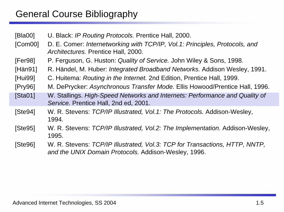
[Bla00] U. Black: IP Routing Protocols. Prentice Hall, 2000.[Com00] D. E. Comer: Internetworking with TCP/IP, Vol.1: Principles, Protocols, and
Architectures. Prentice Hall, 2000.[Fer98] P. Ferguson, G. Huston: Quality of Service. John Wiley & Sons, 1998.[Hän91] R. Händel, M. Huber: Integrated Broadband Networks. Addison Wesley, 1991.[Hui99] C. Huitema: Routing in the Internet. 2nd Edition, Prentice Hall, 1999.[Pry96] M. DePrycker: Asynchronous Transfer Mode. Ellis Howood/Prentice Hall, 1996.[Sta01] W. Stallings. High-Speed Networks and Internets: Performance and Quality of
Service. Prentice Hall, 2nd ed, 2001.[Ste94] W. R. Stevens: TCP/IP Illustrated, Vol.1: The Protocols. Addison-Wesley,
1994.[Ste95] W. R. Stevens: TCP/IP Illustrated, Vol.2: The Implementation. Addison-Wesley,
1995.[Ste96] W. R. Stevens: TCP/IP Illustrated, Vol.3: TCP for Transactions, HTTP, NNTP,
and the UNIX Domain Protocols. Addison-Wesley, 1996.
Advanced Internet Technologies, SS 2004 1.6
History
Situation in the 70sProprietary Protocols (e.g. DECNET, SNA)
GoalsOpen Communication PlatformReliable Data Communication
Development1966: Development of a packet network by DARPA (Defense Advanced Research Projects Agency)Concurrent developments at ”Xerox Palo Alto Research Center“ (PARC)1969: First presentation of the ARPANET1980: Development of TCP/IP1983: TCP/IP became standard for all computers connected to the ARPANET1984: Full TCP/IP support for 4.2BSD and UNIX System VToday: Billions of devices interconnected through the Internet
Advanced Internet Technologies, SS 2004 1.7
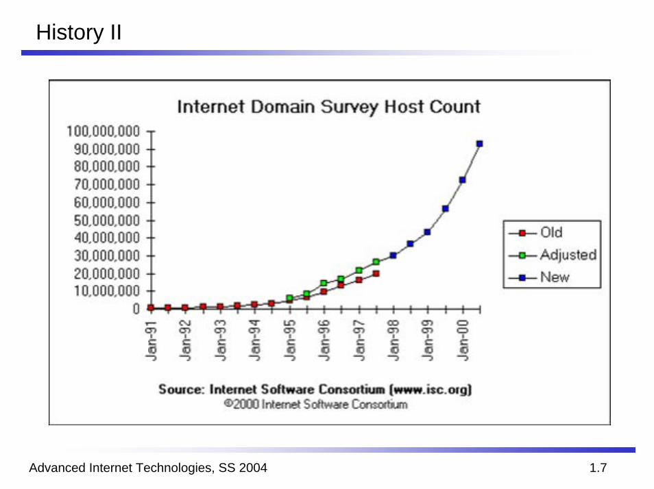
History II
Advanced Internet Technologies, SS 2004 1.8
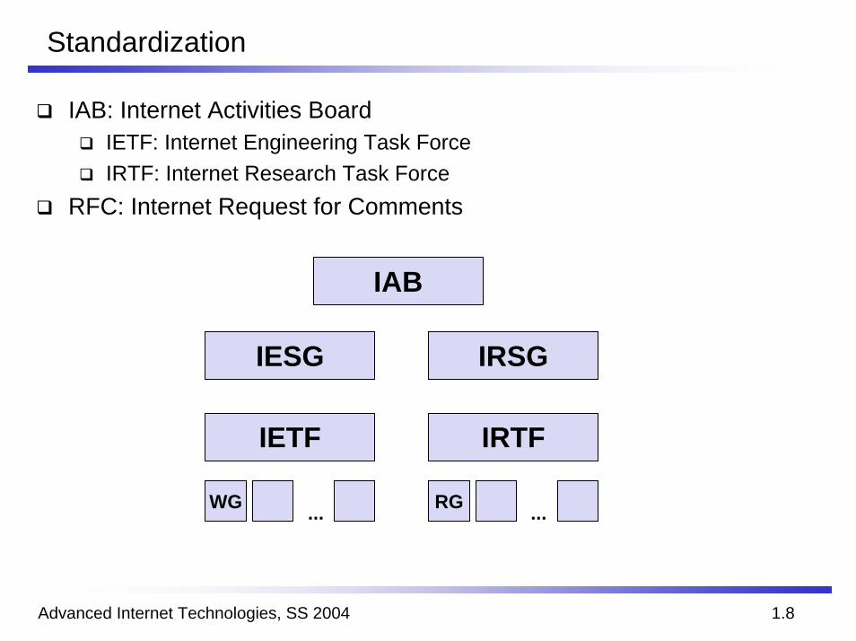
Standardization
IAB: Internet Activities BoardIETF: Internet Engineering Task ForceIRTF: Internet Research Task Force
RFC: Internet Request for Comments
IAB
IESG IRSG
IETF IRTF
WG RG ......
Advanced Internet Technologies, SS 2004 1.9
OSI Reference Model
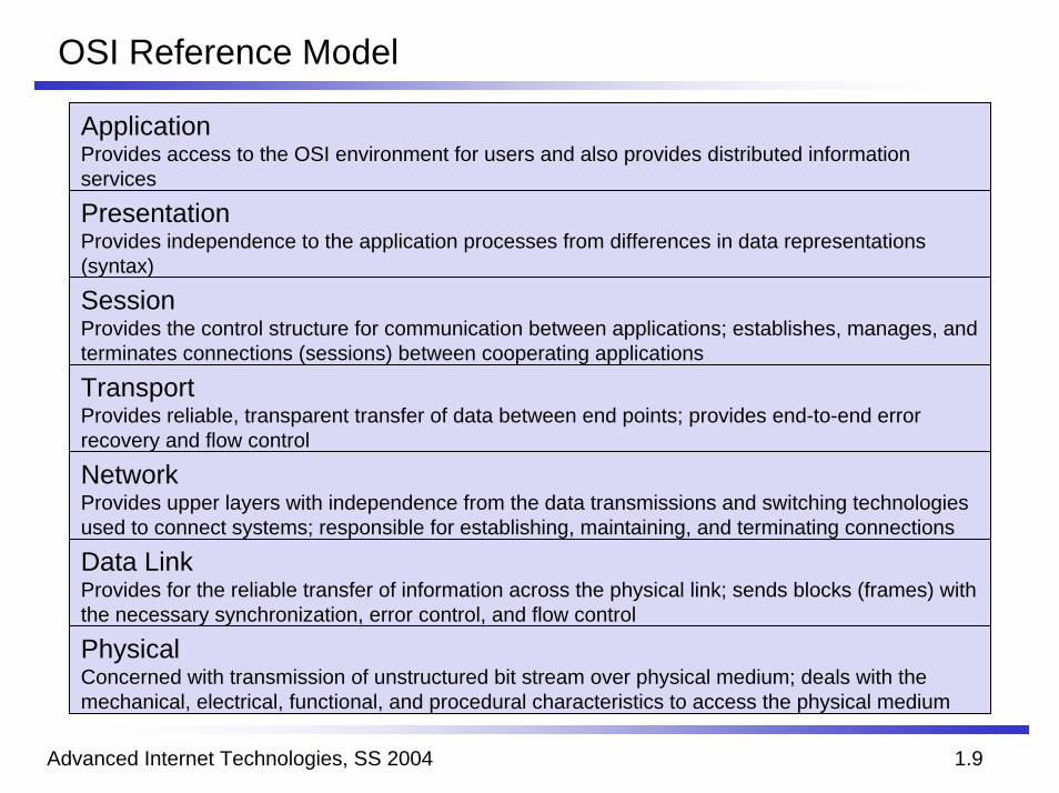
ApplicationProvides access to the OSI environment for users and also provides distributed information services
PresentationProvides independence to the application processes from differences in data representations (syntax)
SessionProvides the control structure for communication between applications; establishes, manages, and terminates connections (sessions) between cooperating applications
TransportProvides reliable, transparent transfer of data between end points; provides end-to-end error recovery and flow control
NetworkProvides upper layers with independence from the data transmissions and switching technologies used to connect systems; responsible for establishing, maintaining, and terminating connections
Data LinkProvides for the reliable transfer of information across the physical link; sends blocks (frames) with the necessary synchronization, error control, and flow control
PhysicalConcerned with transmission of unstructured bit stream over physical medium; deals with the mechanical, electrical, functional, and procedural characteristics to access the physical medium
Advanced Internet Technologies, SS 2004 1.10
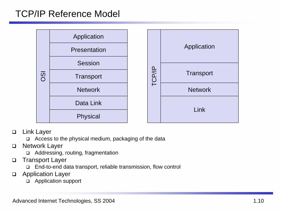
TCP/IP Reference Model
Application
Presentation
Session
Transport
Network
Data Link
Physical
OS
I
Link
Application
Transport
Network
TCP/
IP
Link LayerAccess to the physical medium, packaging of the data
Network LayerAddressing, routing, fragmentation
Transport LayerEnd-to-end data transport, reliable transmission, flow control
Application LayerApplication support
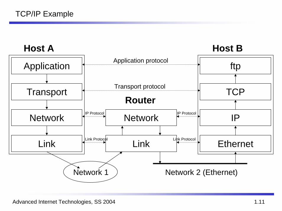
TCP/IP Example
Advanced Internet Technologies, SS 2004 1.11
Host A Host B
Application
Transport
Link
Network
ftp
TCP
Ethernet
IP
Router
Link
NetworkIP Protocol
Link Protocol Link Protocol
IP Protocol
Transport protocol
Application protocol
Network 1 Network 2 (Ethernet)

Advanced Internet Technologies, SS 2004 1.12
TCP/IP Protocol Suite
TCP/IP consists of many sub protocols. Therefore, it is called a protocol suite.
Application
Transport
Network
Link
ApplicationProcess
ApplicationProcess
TCP UDP
ICMP(v4v6) IP(v4v6) ARP RARP
Hardware Interface
Advanced Internet Technologies, SS 2004 1.13
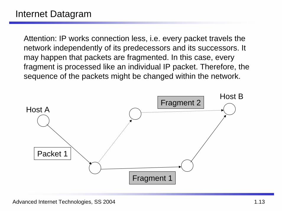
Internet Datagram
Attention: IP works connection less, i.e. every packet travels the network independently of its predecessors and its successors. Itmay happen that packets are fragmented. In this case, every fragment is processed like an individual IP packet. Therefore, the sequence of the packets might be changed within the network.
Host B
Host A
Packet 1
Fragment 2
Fragment 1
Advanced Internet Technologies, SS 2004 1.14
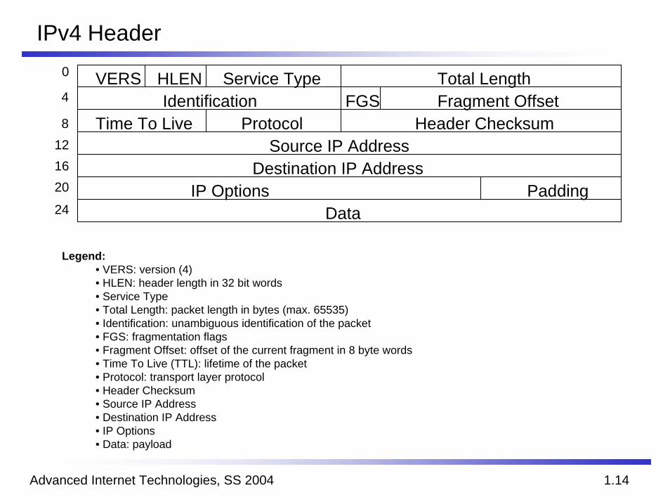
IPv4 Header0 VERS
IdentificationTime To Live Protocol
Service TypeHLEN Total LengthFragment OffsetFGS
Header Checksum
Destination IP AddressIP Options
DataPadding
Source IP Address
4
8121620
24
Legend:• VERS: version (4)• HLEN: header length in 32 bit words• Service Type• Total Length: packet length in bytes (max. 65535)• Identification: unambiguous identification of the packet• FGS: fragmentation flags• Fragment Offset: offset of the current fragment in 8 byte words• Time To Live (TTL): lifetime of the packet• Protocol: transport layer protocol• Header Checksum• Source IP Address• Destination IP Address• IP Options• Data: payload
Advanced Internet Technologies, SS 2004 1.15
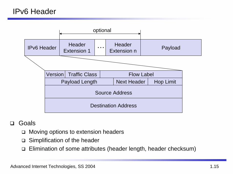
IPv6 Header
IPv6 Header Header Extension 1
Header Extension n Payload…
optional
VersionPayload Length
Source Address
Destination Address
Next Header Hop LimitTraffic Class Flow Label
GoalsMoving options to extension headersSimplification of the headerElimination of some attributes (header length, header checksum)
Advanced Internet Technologies, SS 2004 1.16
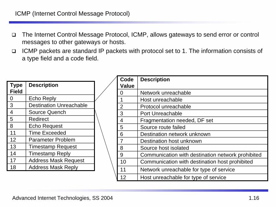
ICMP (Internet Control Message Protocol)
The Internet Control Message Protocol, ICMP, allows gateways to send error or control messages to other gateways or hosts.ICMP packets are standard IP packets with protocol set to 1. The information consists of a type field and a code field.
Code Value
Description
0 Network unreachable1 Host unreachable2 Protocol unreachable3 Port Unreachable4 Fragmentation needed, DF set5 Source route failed6 Destination network unknown7 Destination host unknown8 Source host isolated9 Communication with destination network prohibited10 Communication with destination host prohibited11 Network unreachable for type of service12 Host unreachable for type of service
Type Field
Description
0 Echo Reply3 Destination Unreachable4 Source Quench5 Redirect8 Echo Request11 Time Exceeded12 Parameter Problem13 Timestamp Request14 Timestamp Reply17 Address Mask Request18 Address Mask Reply
Advanced Internet Technologies, SS 2004 1.17
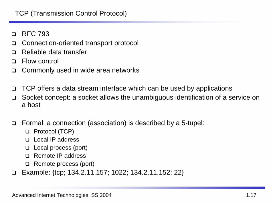
TCP (Transmission Control Protocol)
RFC 793Connection-oriented transport protocolReliable data transferFlow controlCommonly used in wide area networks
TCP offers a data stream interface which can be used by applicationsSocket concept: a socket allows the unambiguous identification of a service on a host
Formal: a connection (association) is described by a 5-tupel:Protocol (TCP)Local IP addressLocal process (port)Remote IP addressRemote process (port)
Example: {tcp; 134.2.11.157; 1022; 134.2.11.152; 22}
Advanced Internet Technologies, SS 2004 1.18
TCP Header
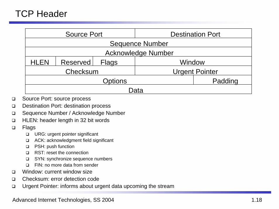
Source Port: source processDestination Port: destination processSequence Number / Acknowledge NumberHLEN: header length in 32 bit wordsFlags
URG: urgent pointer significantACK: acknowledgment field significantPSH: push functionRST: reset the connectionSYN: synchronize sequence numbersFIN: no more data from sender
Window: current window sizeChecksum: error detection codeUrgent Pointer: informs about urgent data upcoming the stream
Sequence Number
HLEN Reserved
Source Port Destination Port
Acknowledge Number
Urgent PointerOptions
DataPadding
WindowFlagsChecksum
Advanced Internet Technologies, SS 2004 1.19
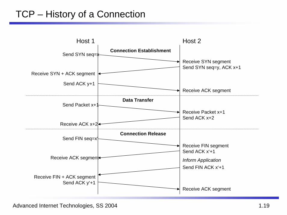
TCP – History of a Connection
Host 2
Receive SYN + ACK segment
Send ACK y+1
Connection Release
Receive SYN segmentSend SYN seq=y, ACK x+1
Send FIN seq=x‘
Receive ACK segment
Receive FIN + ACK segmentSend ACK y‘+1
Receive FIN segmentSend ACK x‘+1
Send FIN ACK x‘+1
Receive ACK segment
Inform Application
Receive ACK x+2
Send Packet x+1Data Transfer
Send SYN seq=xConnection Establishment
Host 1
Receive ACK segment
Receive Packet x+1Send ACK x+2
Advanced Internet Technologies, SS 2004 1.20
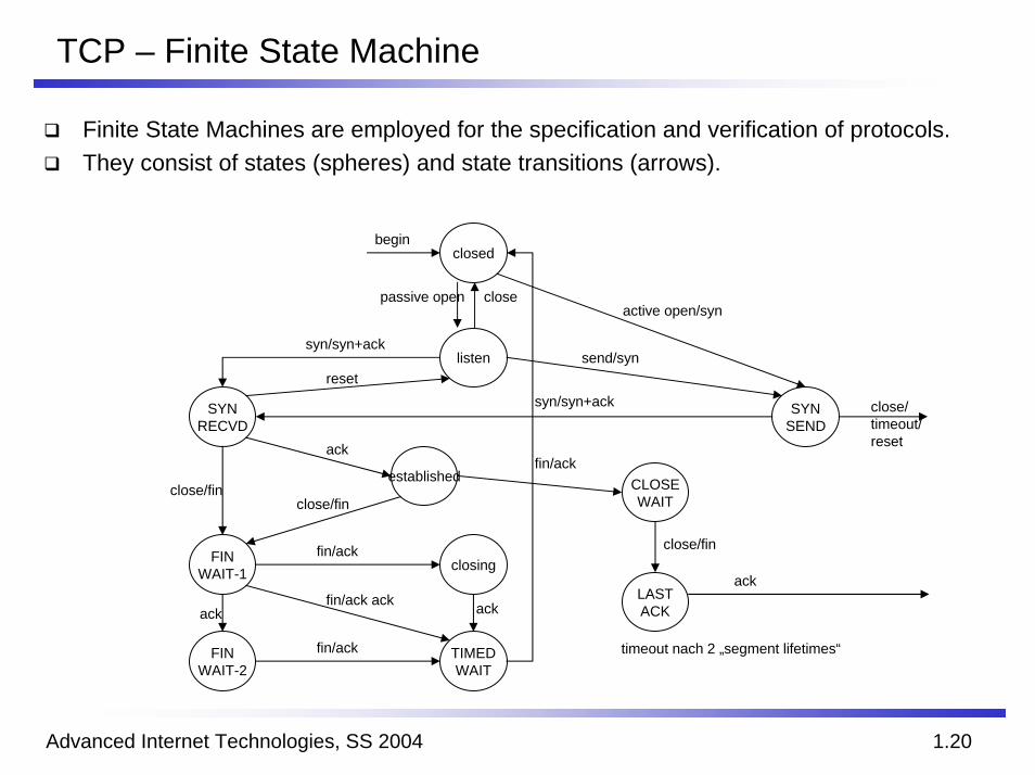
TCP – Finite State Machine
Finite State Machines are employed for the specification and verification of protocols.They consist of states (spheres) and state transitions (arrows).
closed
listen
SYNRECVD
SYNSEND
established
FINWAIT-1
FINWAIT-2
TIMEDWAIT
closing
CLOSEWAIT
LASTACK
fin/ack
fin/ack
fin/ack ackack ack
close/finclose/fin
ack
reset
passive open closeactive open/syn
send/syn
syn/syn+ack close/timeout/reset
begin
syn/syn+ack
fin/ack
close/fin
ack
timeout nach 2 „segment lifetimes“

Advanced Internet Technologies, SS 2004 1.21
UDP (User Datagram Protocol)
RFC 768Connectionless transport protocolUnreliable service (delivery and duplicate protection are not guaranteed)No flow controlMore efficient and robust
Typical application scenariosInward data collection (active or passive sampling of data sources such as sensors)Outward data dissemination (distribution of real-time clock values)Real-time applications (e.g. voice and telemetry)
UDP headerSource port, destination portSegment length, checksum
Advanced Internet Technologies, SS 2004 1.22
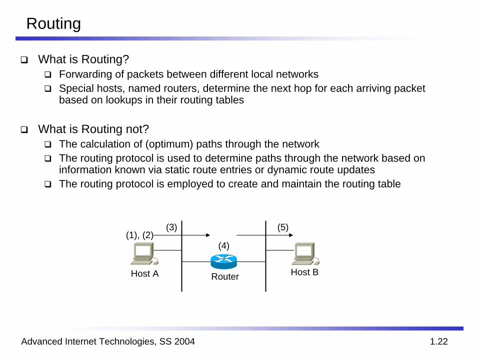
Routing
What is Routing?Forwarding of packets between different local networksSpecial hosts, named routers, determine the next hop for each arriving packet based on lookups in their routing tables
What is Routing not?The calculation of (optimum) paths through the networkThe routing protocol is used to determine paths through the network based on information known via static route entries or dynamic route updatesThe routing protocol is employed to create and maintain the routing table
(3) (5)
Host A Host BRouter
(1), (2)(4)
Advanced Internet Technologies, SS 2004 1.23
Routing Protocols
Static RoutesRouting tables are created and maintained by network administratorsVery simpleEasily to understandWorks for simple topologiesNo redundancy
Dynamic Routing ProtocolsRouter exchange information about the network topologyExtra resources are required
Network bandwidth for route updatesCPU power for route calculations
Works even for complex topologies (depending on the algorithm)Allows redundancy and load balancing
Advanced Internet Technologies, SS 2004 1.24
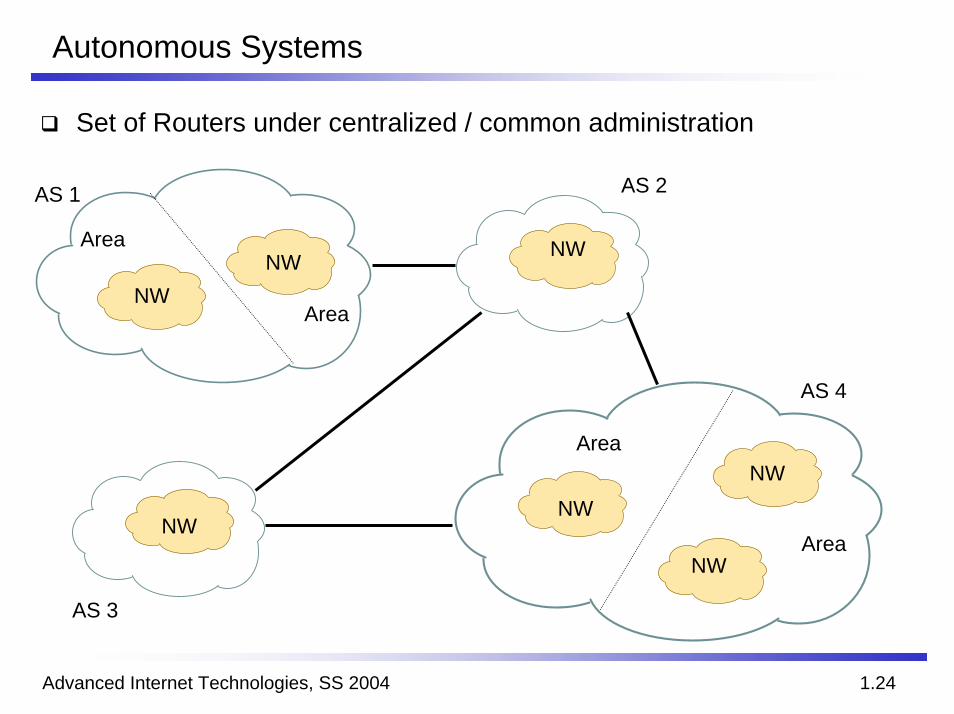
Autonomous Systems
Set of Routers under centralized / common administration
NW
NWNW
NWNWNW
NW
AS 1
Area
Area
Area
Area
AS 3
AS 4
AS 2
Advanced Internet Technologies, SS 2004 1.25
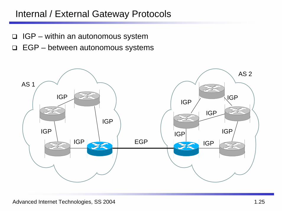
Internal / External Gateway Protocols
IGP – within an autonomous systemEGP – between autonomous systems
EGP
IGP
AS 1AS 2
IGP
IGP
IGP
IGPIGP
IGP
IGP
IGP
IGP
Advanced Internet Technologies, SS 2004 1.26
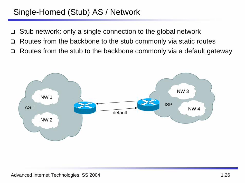
Single-Homed (Stub) AS / Network
Stub network: only a single connection to the global networkRoutes from the backbone to the stub commonly via static routesRoutes from the stub to the backbone commonly via a default gateway
NW 1
NW 2
NW 3
NW 4ISPAS 1
default
Advanced Internet Technologies, SS 2004 1.27
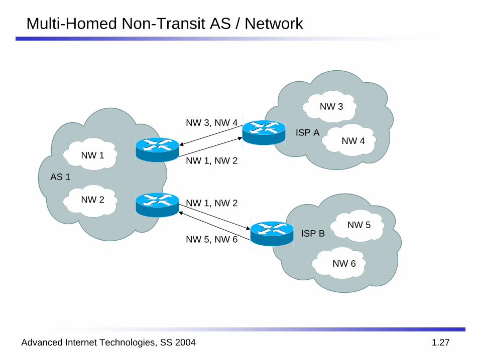
Multi-Homed Non-Transit AS / Network
NW 1
NW 2
NW 3
NW 4
NW 5
NW 6
ISP B
ISP A
AS 1
NW 1, NW 2
NW 3, NW 4
NW 1, NW 2
NW 5, NW 6
Advanced Internet Technologies, SS 2004 1.28
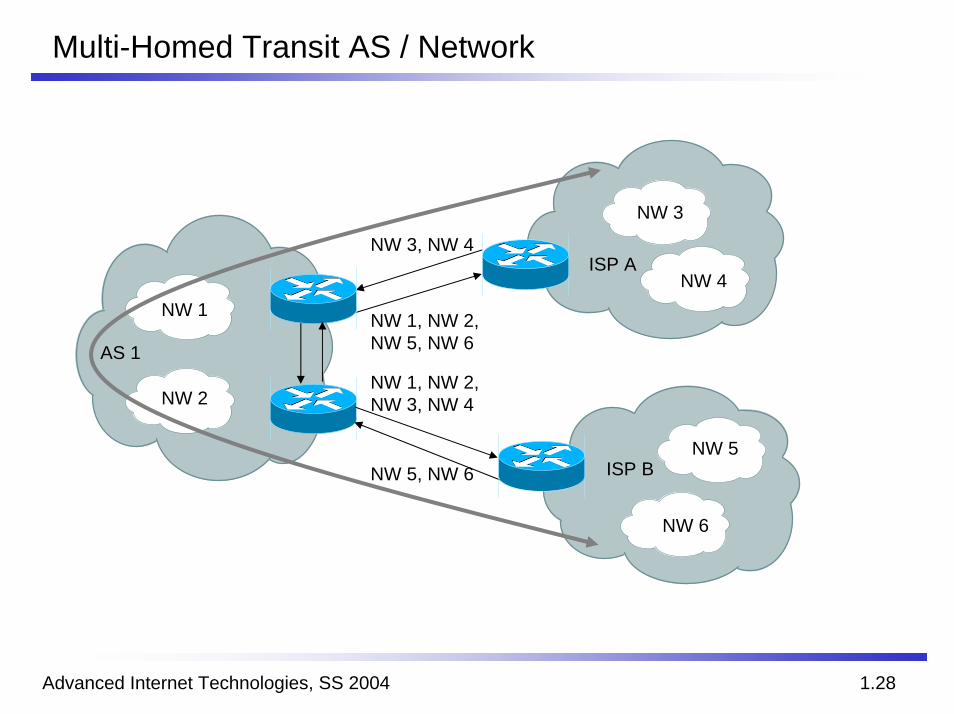
Multi-Homed Transit AS / Network
NW 1
NW 2
NW 3
NW 4
NW 5
NW 6
ISP B
ISP A
AS 1
NW 1, NW 2,NW 5, NW 6
NW 3, NW 4
NW 1, NW 2,NW 3, NW 4
NW 5, NW 6
Advanced Internet Technologies, SS 2004 1.29
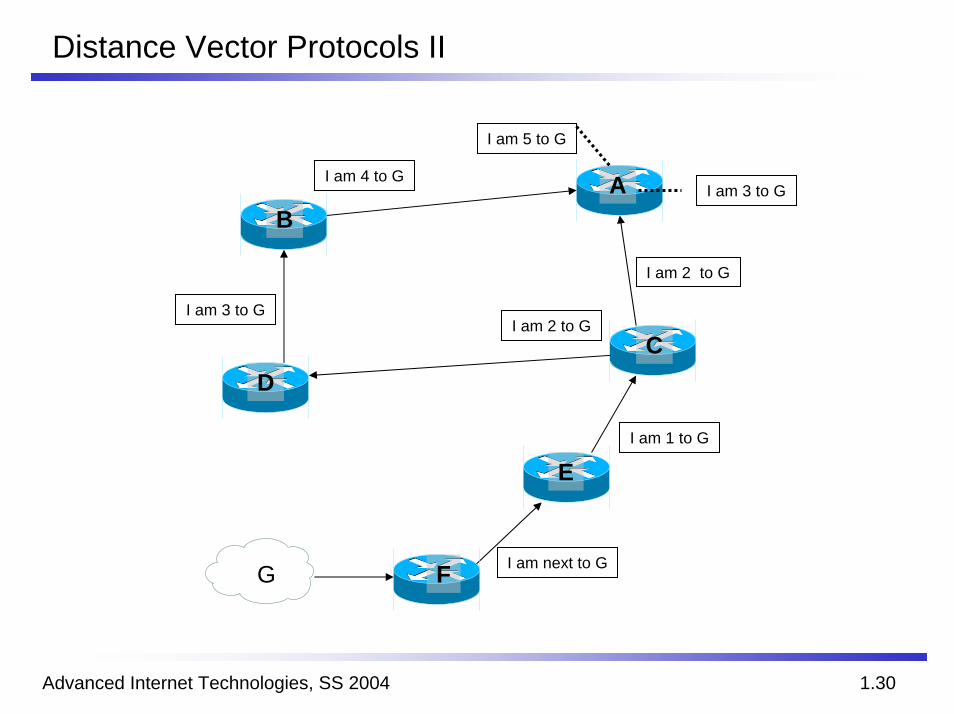
Distance Vector Protocols
PropertiesAlso called minimum hop protocolsVery simpleEasy to maintain
Working principlesEvery router maintains a table with best paths to every known destinationThis table is periodically distributed to each neighbor
ProblemsSlow convergence in case of route changesOnly a single metric for optimum path selection (distance)
Advanced Internet Technologies, SS 2004 1.30
Distance Vector Protocols II
G F
C
E
D
BA
I am next to G
I am 3 to GI am 2 to G
I am 2 to G
I am 1 to G
I am 5 to G
I am 4 to GI am 3 to G
Advanced Internet Technologies, SS 2004 1.31
Link State Protocols
PropertiesEach link has an associated metric (cost factor)The metric can be available bandwidth, monetary costs, link speed etc.
Working principleEvery router has a database with complete information about every router, its interfaces and the associated metricsPeriodically, the database information is distributed to all other routersThe routing table is calculated using the database and a shortest path algorithm
ProblemsHigh resource requirements (memory, CPU)
Advanced Internet Technologies, SS 2004 1.32
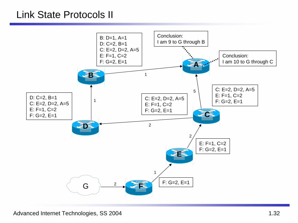
Link State Protocols II
Conclusion:I am 9 to G through B
G F
C
E
D
BA
F: G=2, E=1
C: E=2, D=2, A=5E: F=1, C=2F: G=2, E=1
E: F=1, C=2F: G=2, E=1
2
2
2
1
5
1
B: D=1, A=1D: C=2, B=1C: E=2, D=2, A=5E: F=1, C=2F: G=2, E=1
Conclusion:I am 10 to G through C
C: E=2, D=2, A=5E: F=1, C=2F: G=2, E=1
D: C=2, B=1C: E=2, D=2, A=5E: F=1, C=2F: G=2, E=1
1
Advanced Internet Technologies, SS 2004 1.33
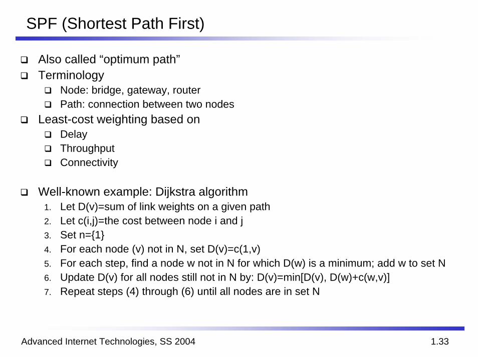
SPF (Shortest Path First)
Also called “optimum path”Terminology
Node: bridge, gateway, routerPath: connection between two nodes
Least-cost weighting based onDelayThroughputConnectivity
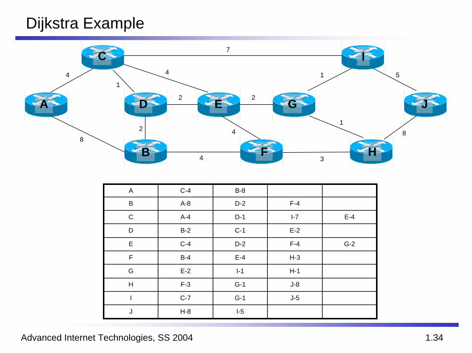
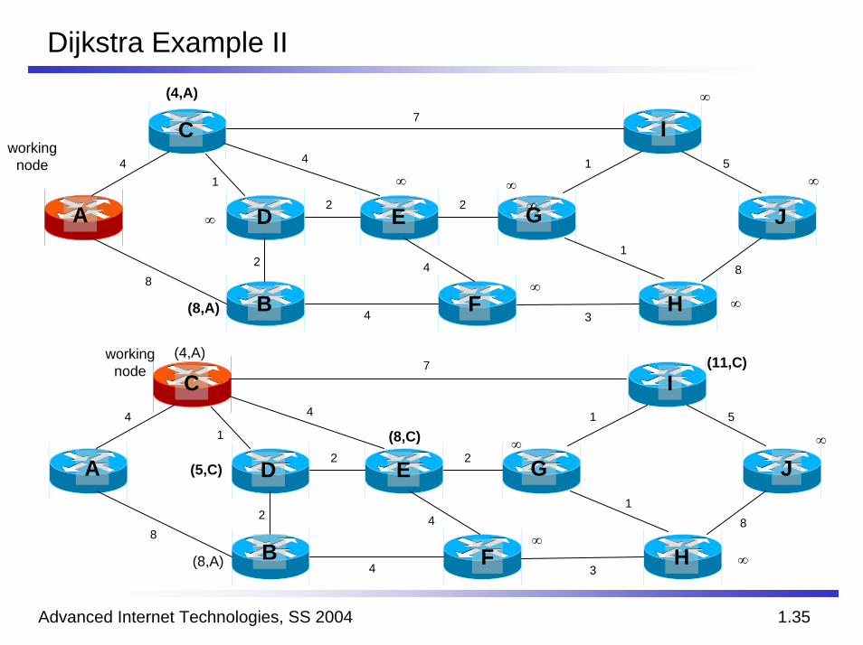
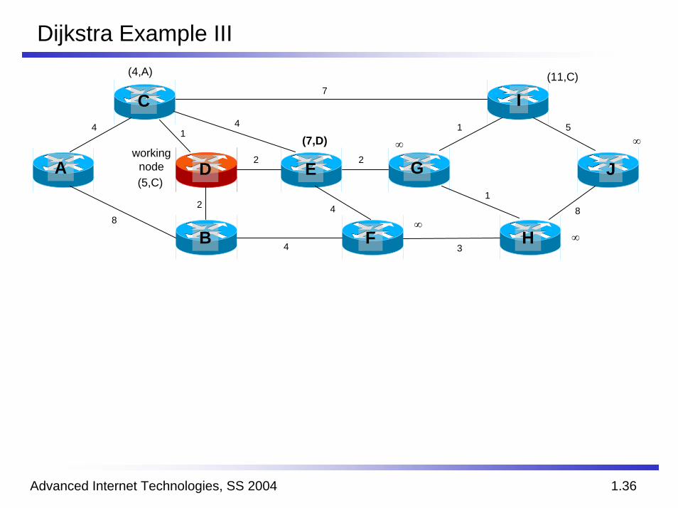
Well-known example: Dijkstra algorithm1. Let D(v)=sum of link weights on a given path2. Let c(i,j)=the cost between node i and j3. Set n={1}4. For each node (v) not in N, set D(v)=c(1,v)5. For each step, find a node w not in N for which D(w) is a minimum; add w to set N6. Update D(v) for all nodes still not in N by: D(v)=min[D(v), D(w)+c(w,v)]7. Repeat steps (4) through (6) until all nodes are in set N
Advanced Internet Technologies, SS 2004 1.34
Dijkstra Example
2
8
4
14
81
51
4
7
2
2
4 3
A G
I
E J
HF
C
D
B
A C-4 B-8
B A-8 D-2 F-4
C A-4 D-1 I-7 E-4
D B-2 C-1 E-2
E C-4 D-2 F-4 G-2
F B-4 E-4 H-3
G E-2 I-1 H-1
H F-3 G-1 J-8
I C-7 G-1 J-5
J H-8 I-5
Advanced Internet Technologies, SS 2004 1.35
Dijkstra Example II(4,A)
2
8
4
14
81
51
4
∞7
4 3
2
2A G
I
E J
HF
C
D
B
workingnode
2
8
4
14
81
51
4
4 3
7
2
2A G
I
E J
HF
C
D
B
(8,A)
∞∞
∞ ∞
∞
∞∞
workingnode
(4,A) (11,C)
(8,C)
(8,A)
∞ ∞
(5,C)
∞∞
Advanced Internet Technologies, SS 2004 1.36
Dijkstra Example III(4,A)
2
8
414
81
51
4
7
4 3
2
2A G
I
E J
HF
C
D
B
(5,C)
∞
(11,C)
workingnode
(7,D) ∞
∞∞
Advanced Internet Technologies, SS 2004 1.37
Dijkstra Example IV
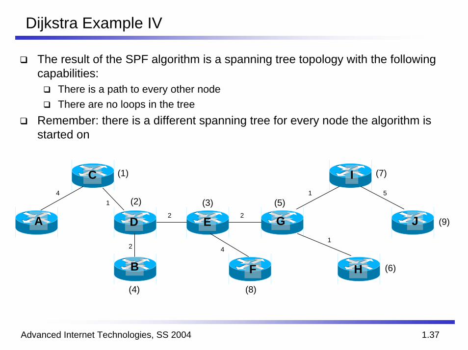
The result of the SPF algorithm is a spanning tree topology with the following capabilities:
There is a path to every other nodeThere are no loops in the tree
Remember: there is a different spanning tree for every node the algorithm is started on
2
14
1
51
42
2A G
I
E J
HF
C
D
B
(7)(1)
(2) (3) (5)
(9)
(6)
(4) (8)
Advanced Internet Technologies, SS 2004 1.38
RIP – Routing Information Protocol
RFC 1058Developed by Ford und Fulkerson; also known as Ford-Fulkerson algorithmVery simple distance vector protocolHop count is the only metric
RIPv1 does not support variable length netmasks (Classless Interdomain Routing, CIDR)
Working principleMaximum hop count: 16 (infinity)Distribution of network addresses and distances (hop count)Periodically broadcast (every 30 sec)180 sec without a new update: route is marked unusable240 sec without a new update: route is removed
Advanced Internet Technologies, SS 2004 1.39
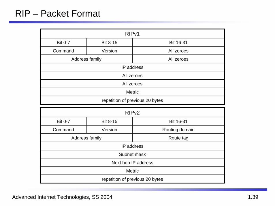
RIP – Packet Format
RIPv1Bit 0-7 Bit 8-15 Bit 16-31
Command Version All zeroes
Address family All zeroes
IP address
All zeroes
All zeroes
Metric
repetition of previous 20 bytes
repetition of previous 20 bytes
Metric
Next hop IP address
Subnet mask
IP address
Route tagAddress family
Routing domainVersionCommand
Bit 16-31Bit 8-15Bit 0-7
RIPv2
Advanced Internet Technologies, SS 2004 1.40
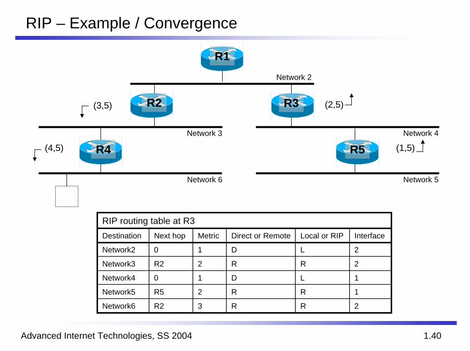
RIP – Example / Convergence
(2,5)
(1,5)
Network 6 Network 5
Network 4Network 3
Network 2
(3,5)
(4,5)
R2
R5
R3
R4
R1
RIP routing table at R3Destination Next hop Metric Direct or Remote Local or RIP Interface
Network2 0 1 D L 2
Network3 R2 2 R R 2
Network4 0 1 D L 1
Network5 R5 2 R R 1
Network6 R2 3 R R 2
Advanced Internet Technologies, SS 2004 1.41
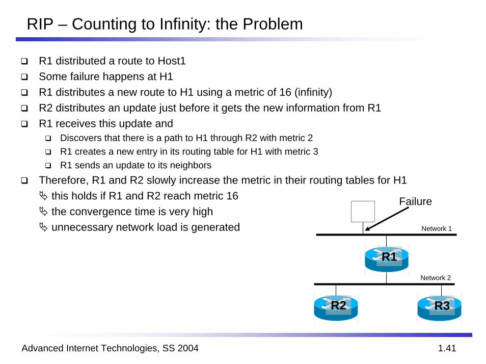
RIP – Counting to Infinity: the Problem
R1 distributed a route to Host1Some failure happens at H1R1 distributes a new route to H1 using a metric of 16 (infinity)R2 distributes an update just before it gets the new information from R1R1 receives this update and
Discovers that there is a path to H1 through R2 with metric 2R1 creates a new entry in its routing table for H1 with metric 3R1 sends an update to its neighbors
Therefore, R1 and R2 slowly increase the metric in their routing tables for H1this holds if R1 and R2 reach metric 16the convergence time is very highunnecessary network load is generated
R1
R2 R3
Network 1
Failure
Network 2
Advanced Internet Technologies, SS 2004 1.42
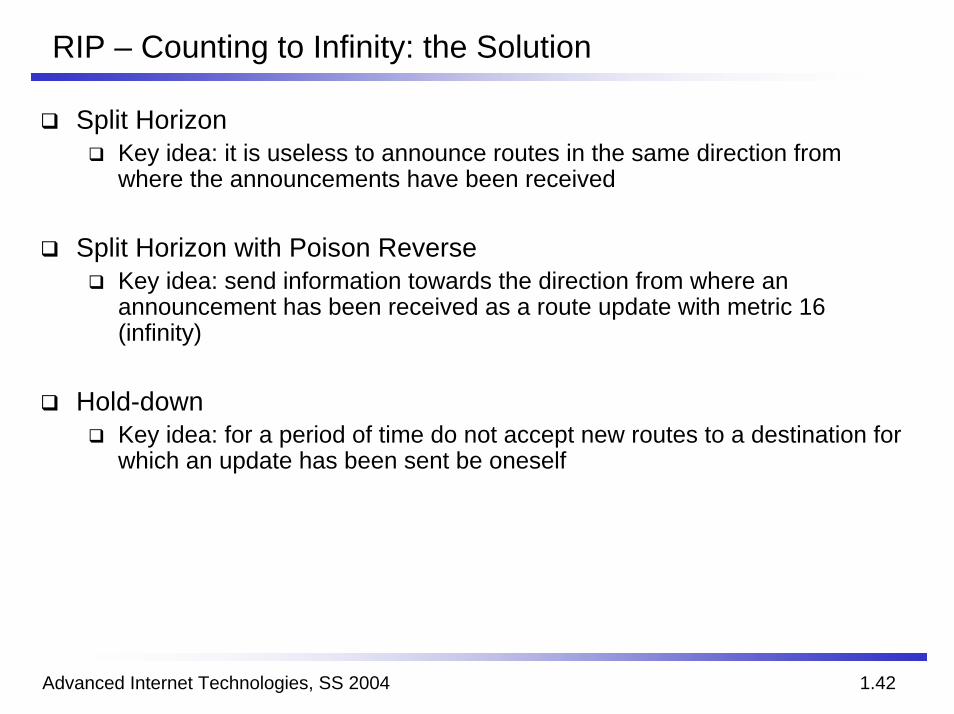
RIP – Counting to Infinity: the Solution
Split HorizonKey idea: it is useless to announce routes in the same direction from where the announcements have been received
Split Horizon with Poison ReverseKey idea: send information towards the direction from where an announcement has been received as a route update with metric 16 (infinity)
Hold-downKey idea: for a period of time do not accept new routes to a destination for which an update has been sent be oneself

Advanced Internet Technologies, SS 2004 1.43
OSPF – Open Shortest Path First
Developed by J. MoyOSPFv1: RFC 1131, 1245, 1246OSPFv2: RFC 1247, 1253Link state protocol
AdvantagesSupport for flexible metrics for routing decisions (e.g. distance, throughput, current load, $$)Large range of values for the metric (1 to 65535)Scalability (2-level hierarchy)Support for multiple paths (equal path load sharing, unequal path load sharing)Support for asymmetric metrics (based on directed graphs)Support for secured messages (MD5 checksum)
Advanced Internet Technologies, SS 2004 1.44
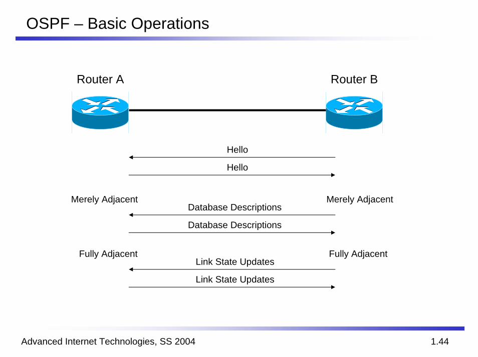
OSPF – Basic Operations
Router A Router B
Hello
Hello
Merely Adjacent Merely AdjacentDatabase Descriptions
Database Descriptions
Fully Adjacent Fully AdjacentLink State Updates
Link State Updates
Advanced Internet Technologies, SS 2004 1.45
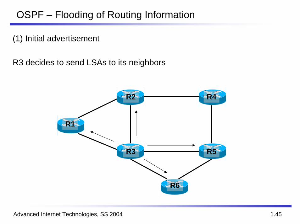
OSPF – Flooding of Routing Information
(1) Initial advertisement
R3 decides to send LSAs to its neighbors
R2
R5
R6
R3
R1
R4
Advanced Internet Technologies, SS 2004 1.46
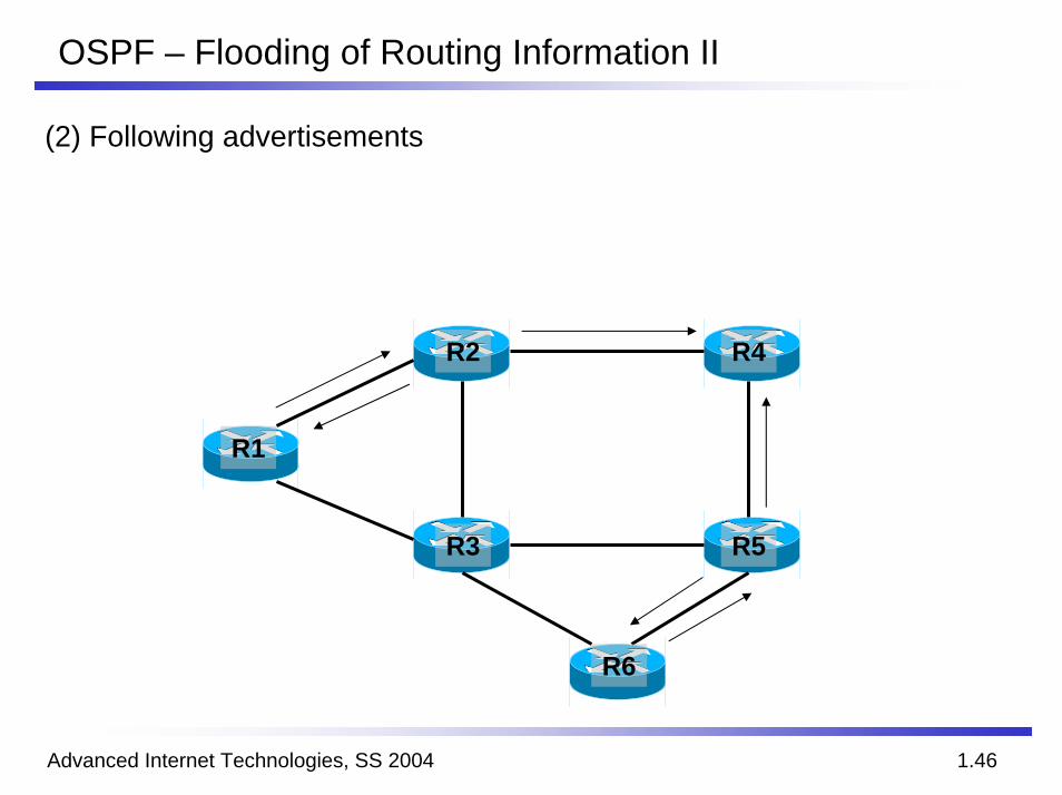
OSPF – Flooding of Routing Information II
(2) Following advertisements
R2
R5
R6
R3
R1
R4
Advanced Internet Technologies, SS 2004 1.47
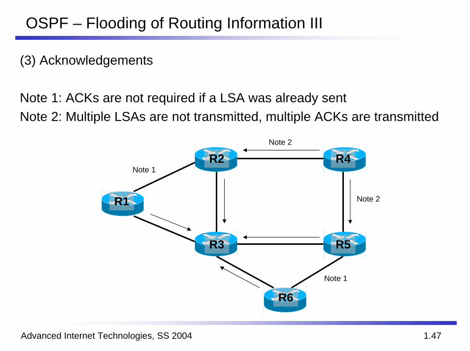
OSPF – Flooding of Routing Information III
(3) Acknowledgements
Note 1: ACKs are not required if a LSA was already sentNote 2: Multiple LSAs are not transmitted, multiple ACKs are transmitted
R2
R5
R6
R3
R1
R4Note 1
Note 1
Note 2
Note 2
Advanced Internet Technologies, SS 2004 1.48
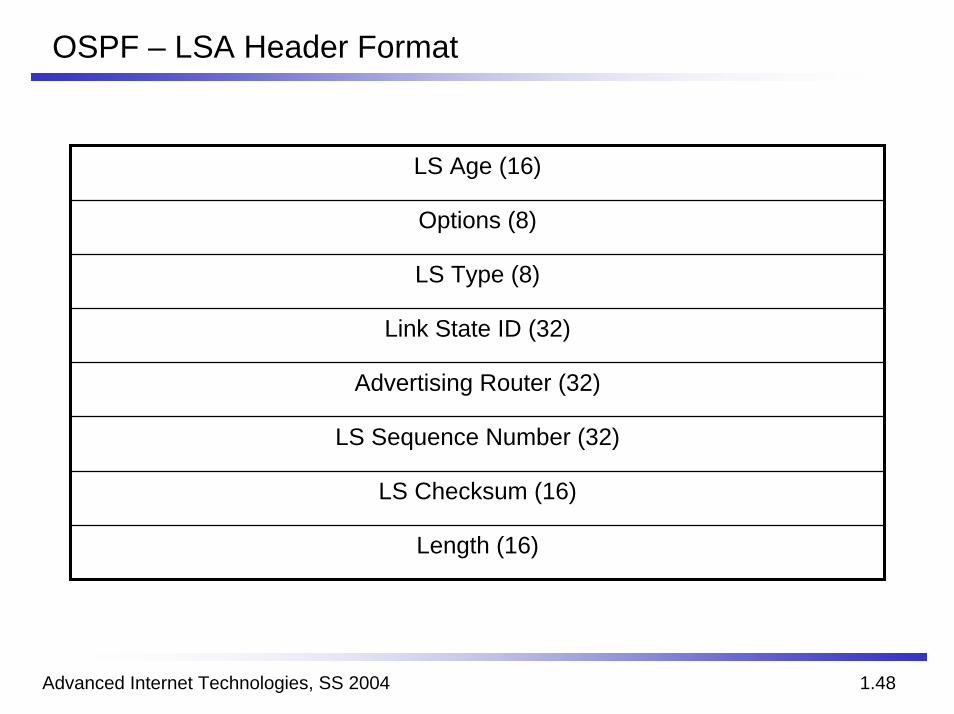
OSPF – LSA Header Format
LS Age (16)
Options (8)
LS Type (8)
Link State ID (32)
Advertising Router (32)
LS Sequence Number (32)
LS Checksum (16)
Length (16)
Advanced Internet Technologies, SS 2004 1.49
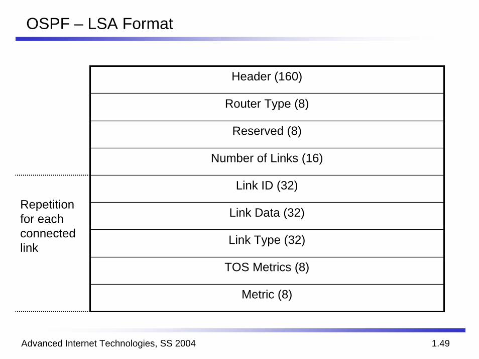
OSPF – LSA Format
Header (160)
Router Type (8)
Reserved (8)
Number of Links (16)
Link ID (32)
Link Data (32)
Link Type (32)
TOS Metrics (8)
Metric (8)
Repetitionfor eachconnectedlink
Advanced Internet Technologies, SS 2004 1.50
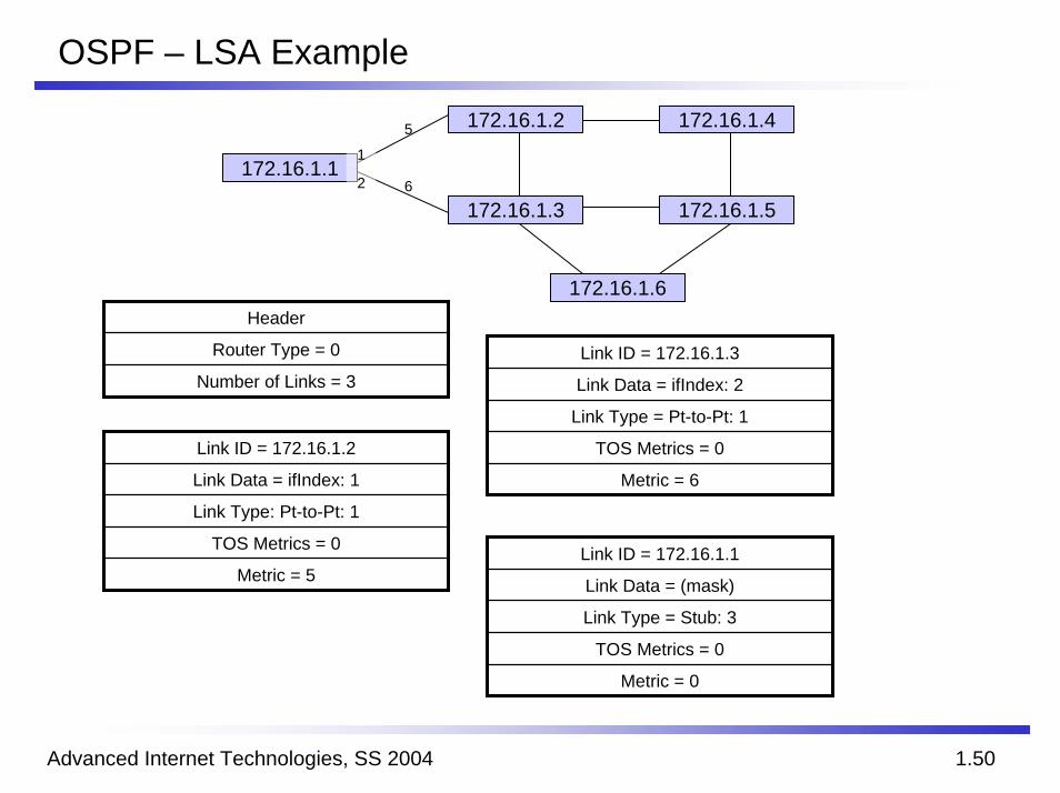
OSPF – LSA Example
172.16.1.6
172.16.1.1
172.16.1.3 172.16.1.5
172.16.1.4172.16.1.2
6
5
1
2
Header
Router Type = 0
Number of Links = 3Link ID = 172.16.1.3
Link Data = ifIndex: 2
Link Type = Pt-to-Pt: 1
TOS Metrics = 0
Metric = 6
Link ID = 172.16.1.2
Link Data = ifIndex: 1
Link Type: Pt-to-Pt: 1
TOS Metrics = 0
Metric = 5Link ID = 172.16.1.1
Link Data = (mask)
Link Type = Stub: 3
TOS Metrics = 0
Metric = 0
Advanced Internet Technologies, SS 2004 1.51
OSPF – Areas
Problem in very large networksThe number of LSAs increases dramatically, therefore, the network load is increased as well
SolutionEstablishment of multiple areasEstablishment of designated routers (DRs)Prevention of the requirement that each router has to have a complete knowledge about the complete network
AdvantagesReduction of the size of the local database at each routerReduction of the number of LSAs in the network
Advanced Internet Technologies, SS 2004 1.52
OSPF – Designated Router
OSPF defines a DR for every networkElection based on the highest IP addressElection may be manipulated by using administrative prioritiesTypically, IP multicast is employed for the election (group 224.0.0.5)
In point-to-point topologies, every router has exactly one neighborIn broadcast networks with n deployed OSPF routers, every router has n x (n -1)/2 neighbors
The DR is employed to reduce the number of neighbor ship relationsTo increase the reliability, a backup DB (BDR) is elected
Advanced Internet Technologies, SS 2004 1.53
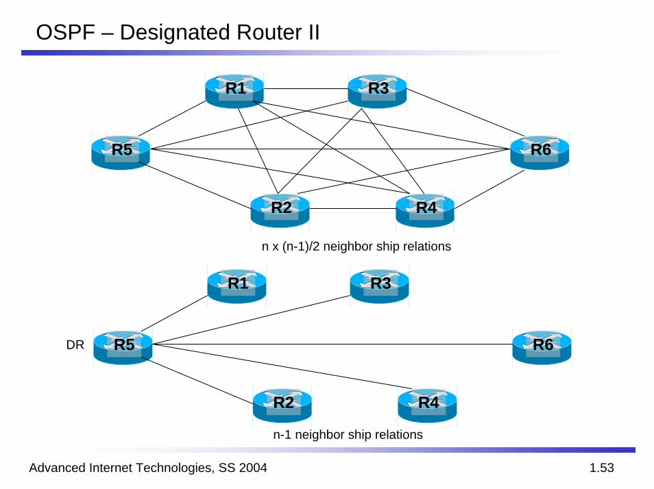
OSPF – Designated Router II
R5 R6
R1 R3
R2 R4
R5 R6
R1 R3
R2 R4
n x (n-1)/2 neighbor ship relations
DR
n-1 neighbor ship relations