Embed Size (px)
Citation preview
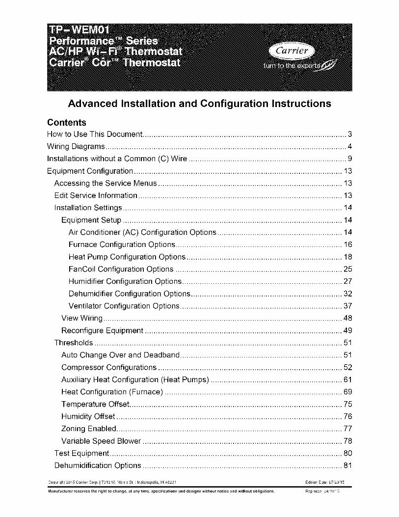
Advanced Installation and Configuration Instructions
ContentsHow to Use This Document ............................................................................................. 3
Wiring Diagrams .............................................................................................................. 4
Installations without a Common (C) Wire ........................................................................ 9
Equipment Configuration ............................................................................................... 13
Accessing the Service Menus .................................................................................... 13
Edit Service Information ............................................................................................. 13
Installation Settings .................................................................................................... 14
Equipment Setup .................................................................................................... 14
Air Conditioner (AC) Configuration Options ......................................................... 14
Furnace Configuration Options ............................................................................ 16
Heat Pump Configuration Options ....................................................................... 18
FanCoil Configuration Options ............................................................................ 25
Humidifier Configuration Options ......................................................................... 27
Dehumidifier Configuration Options ..................................................................... 32
Ventilator Configuration Options .......................................................................... 37
View Wiring ............................................................................................................. 48
Reconfigure Equipment .......................................................................................... 49
Thresholds ................................................................................................................. 51
Auto Change Over and Deadband .......................................................................... 51
Compressor Configurations .................................................................................... 52
Auxiliary Heat Configuration (Heat Pumps) ............................................................ 61
Heat Configuration (Furnace) ................................................................................. 69
Temperature Offset ................................................................................................. 75
Humidity Offset ....................................................................................................... 76
Zoning Enabled ....................................................................................................... 77
Variable Speed Blower ........................................................................................... 78
Test Equipment .......................................................................................................... 80
Dehumidification Options ........................................................................................... 81
Copyright 21315 Carrier Corp. I 7310 W. Morris St. I Indianapolis, IN 46231 Edition Date: 07/20/15
Manufacturer reserves the right to change, at any time, specifications and designs without notice and without obligations. Replaces: 04/19/15
Dehumidification Options for Most Cooling Equipment ........................................... 81
Cool to Dehumidify .............................................................................................. 81
Dehumidification Options with Variable Speed Carrier Equipment ......................... 82
Standard Dehumidification .................................................................................. 82
Ideal Humidity System ® Technology (Standard Dehumidification + SuperDehumidification) ................................................................................................. 83
Ideal Humidity System ® Technology with FK/FV Fan Coils .................................... 84
Standard Dehumidification with FV/FK Fan Coils ................................................... 88
Standard Dehumidification with FX4 Multi-tap ECM Fan Coils ............................... 92
Ideal Humidity System ® Technology with Infinity ® Furnaces ................................... 95
Furnace Dehumidification with Performance Furnaces .......................................... 98
Furnace Dehumidification with Tapped ECM Motors ............................................ 100
Furnace Dehumidification with 58DLA/DLX, 58CTA/58CTX Models .................... 103
Standard Dehumidification with Geothermal ......................................................... 104
Dehumidification with an Accessory Dehumidifier ................................................ 106
Vacation Dehumidification .................................................................................... 107
Frequently Asked Questions ....................................................................................... 107
21Page
How to Use This DocumentThe advanced installation and configuration instructions are intended to supplement thestandard installation instructions shipped with the thermostat or available for downloadon www.HVACpartners.com. The advanced settings and configuration options detailedin this document are intended for professional installers only. Incorrect configurationmay lead to improper operation and equipment damage.
Each section of this document is outlined in the following structure:
Section TitleLocation of this section within the thermostat menus
Image showing available features in this section on the thermostat
Feature Title
Feature Description
• Default Configuration• Configuration Options
Image showing screen on the thermostat
31Page
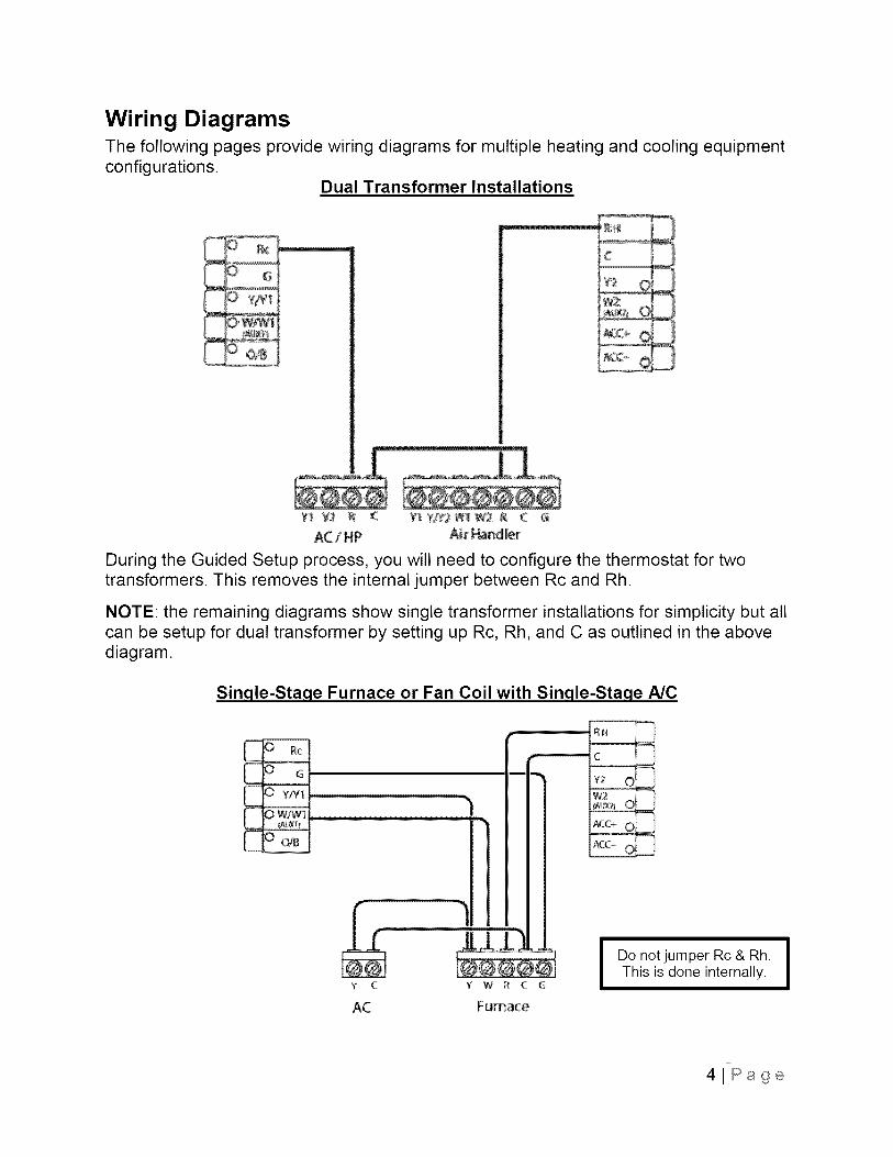
Wiring DiagramsThe following pages provide wiring diagrams for multiple heating and cooling equipmentconfigurations.
Dual Transformer Installations
+
/
;+++
++ ++ + ( +++++2¥+Wt+++ R + G
AC/H+P A# _ _r
During the Guided Setup process, you will need to configure the thermostat for twotransformers. This removes the internal jumper between Rc and Rh.
NOTE: the remaining diagrams show single transformer installations for simplicity but allcan be setup for dual transformer by setting up Rc, Rh, and C as outlined in the abovediagram.
Single-Stage Furnace or Fan Coil with Single-Stage A/C
RN
C
w2Y2 O
N20, ©
y C Y W R C
AC Furnace
I Do not jumper Rc& Rh. I
I
This is done internally, I
41Page
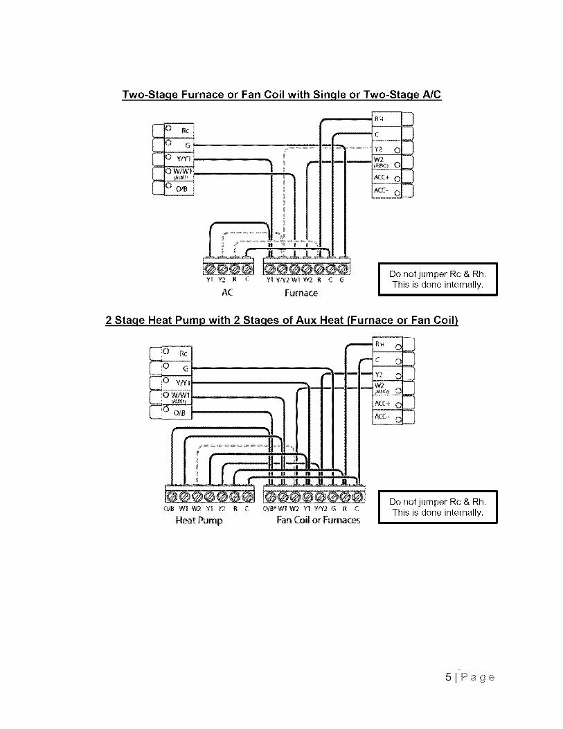
Two-Staqe Furnace or Fan Coil with Sinqle or Two-Staqe A/C
10
R H
c_
Y2_
W2
ACC4_
13
Y!_ Y2 R C YI Y/Y2WI W2 R C G
AC FurnaceI Do not jumper Rc& Rh. I
I
This is done internally, I
2 Stage Heat Pump with 2 Staqes of Aux Heat (Furnace or Fan Coil)
GtB WI W2 Y} Y2 R C O/g_W]W2 Y1 WY2 G R C
Heat Pump Fan Coil or FurnacesI Do not jumper Rc& Rh. I
I
This is done internally, I
51Page
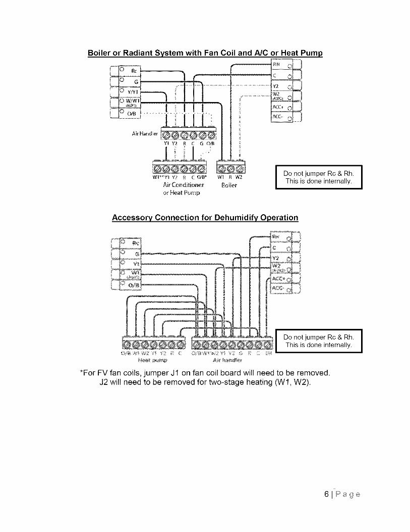
Boiler or Radiant System with Fan Coil and A/C
Air Handler
YI Y2 I C G OiB
rC O
or Heat Pump
RH 0 3
Y2 0 3
_×_ 0
_X;,+ 0
ACC, 03
£!_*Y]; Y2 R C 0/8 '_ W1 i W2
Air Conditioner Boiler
ot Heat Pump
I Do not jumper Rc& Rh. I
I
This is done internally. I
Accessory Connection for Dehumidify Operation
SS+
S¢o_b
Do not jumper Rc & Rh.This is done internally.
*For FV fan coils, jumper J1 on fan coil board will need to be removed.J2 will need to be removed for two-stage heating (W1, W2).
I
6lPage
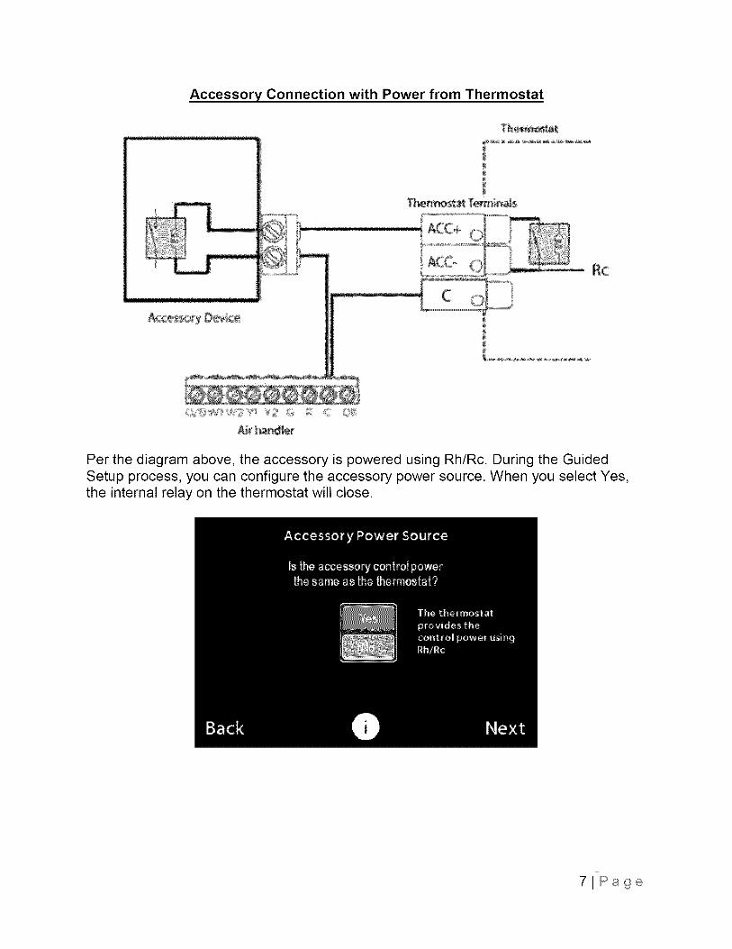
Accessory Connection with Power from Thermostat
Per the diagram above, the accessory is powered using Rh/Rc. During the GuidedSetup process, you can configure the accessory power source. When you select Yes,the internal relay on the thermostat will close.
71Page
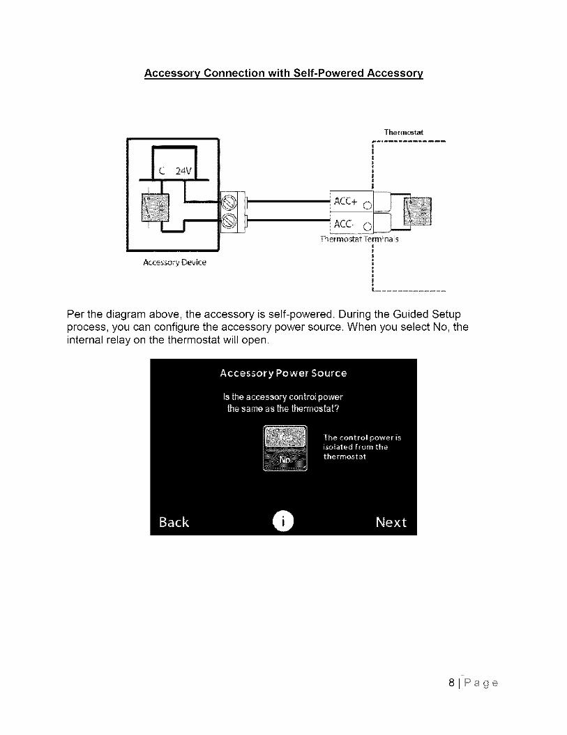
Accessory Connection with Self-Powered Accessory
C 24V[
Accessory Device
Thermostat
|||
|
|
ACC+ 0
ACC-
Thermostat Terminals
Per the diagram above, the accessory is self-powered. During the Guided Setupprocess, you can configure the accessory power source. When you select No, theinternal relay on the thermostat will open.
81Page
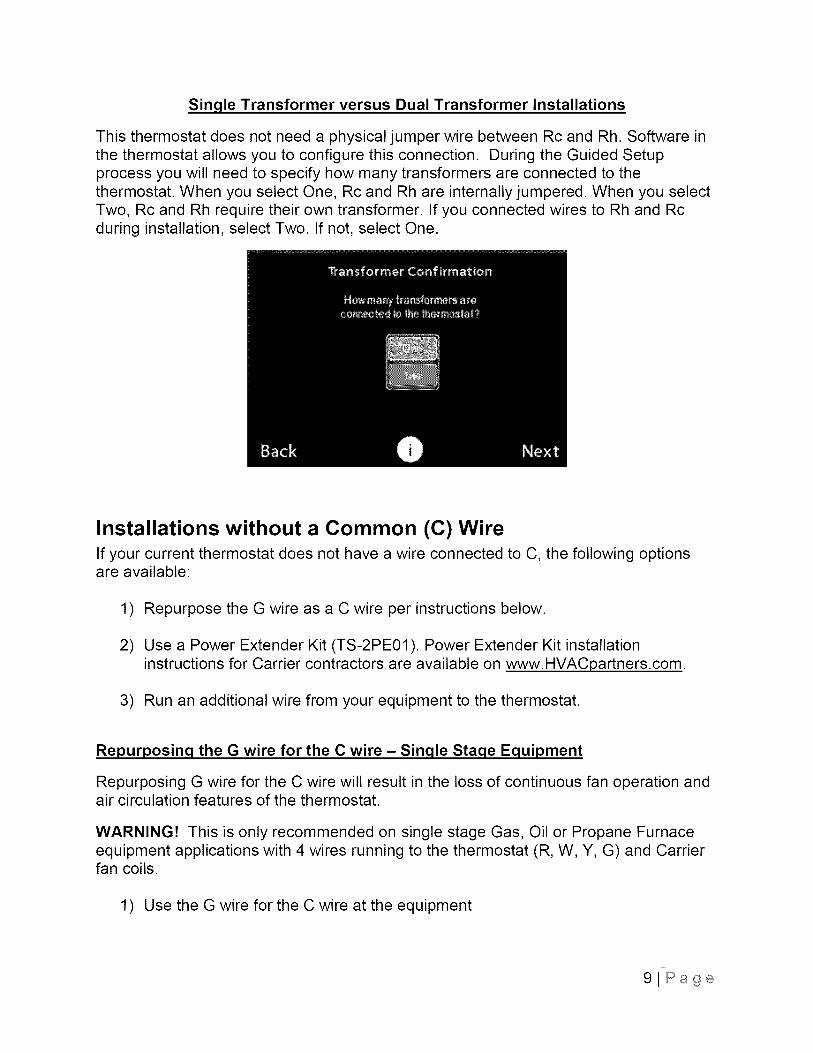
Single Transformer versus Dual Transformer Installations
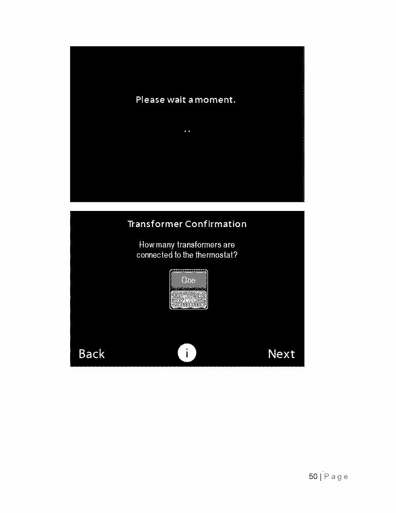
This thermostat does not need a physical jumper wire between Rc and Rh. Software inthe thermostat allows you to configure this connection. During the Guided Setupprocess you will need to specify how many transformers are connected to thethermostat. When you select One, Rc and Rh are internally jumpered. When you selectTwo, Rc and Rh require their own transformer. If you connected wires to Rh and Rcduring installation, select Two. If not, select One.
Installations without a Common (C) WireIf your current thermostat does not have a wire connected to C, the following optionsare available:
1) Repurpose the G wire as a C wire per instructions below.
2) Use a Power Extender Kit (TS-2PE01). Power Extender Kit installationinstructions for Carrier contractors are available on www.HVACpartners.com.
3) Run an additional wire from your equipment to the thermostat.
Repurposing the G wire for the C wire - Single Stage Equipment
Repurposing G wire for the C wire will result in the loss of continuous fan operation andair circulation features of the thermostat.
WARNING! This is only recommended on single stage Gas, Oil or Propane Furnaceequipment applications with 4 wires running to the thermostat (R, W, Y, G) and Carrierfan coils.
1) Use the G wire for the C wire at the equipment
91Page
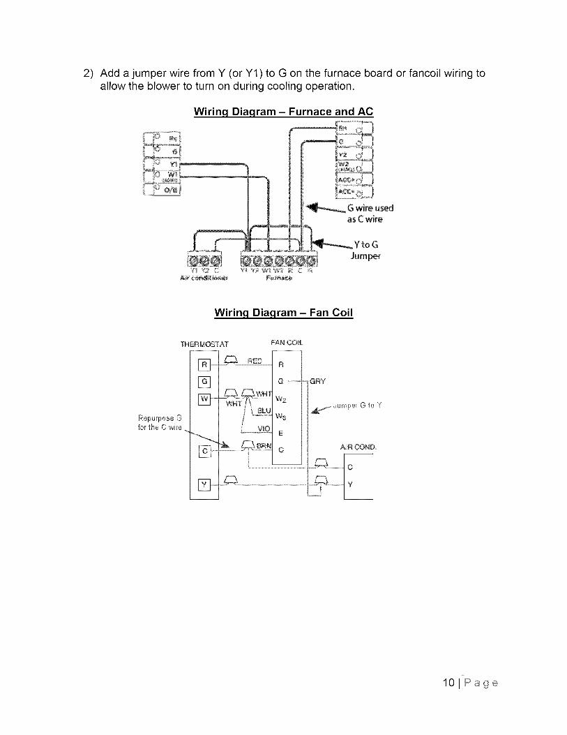
2) Add a jumper wire from Y (or Y1) to G on the furnace board or fancoil wiring toallow the blower to turn on during cooling operation.
Wirinq Diagram - Furnace and AC
/. |I _ Gwi,o.,_
I asCwire
I_ ....L .....L "
Wiring Diagram - Fan Coil
THERMOSTAT
Repurpose Gfot the C 'wire
%
_ BRN
FAN CO_L
R
W2
W_
E
C
GRY
Jumper G to Y
lOIPage
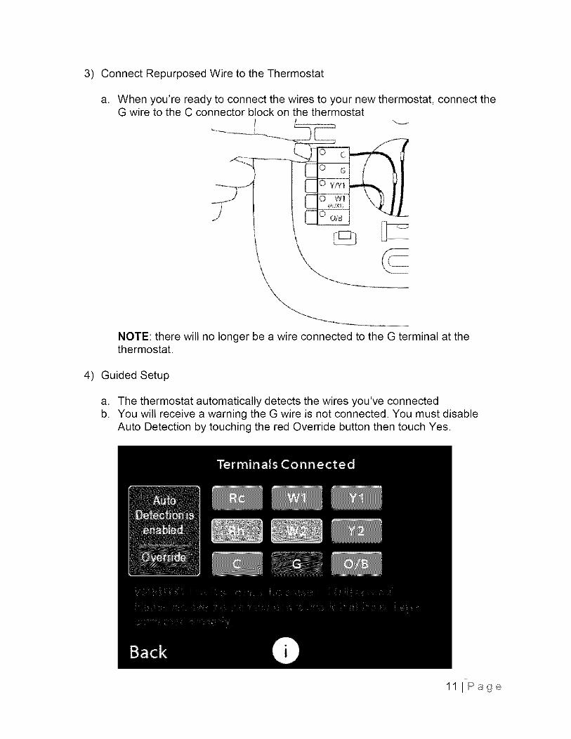
3) Connect Repurposed Wire to the Thermostat
a. When you're ready to connect the wires to your new thermostat, connect theG wire to the C connector block on the thermostat
NOTE: there will no longer be a wire connected to the G terminal at thethermostat.
4) Guided Setup
a. The thermostat automatically detects the wires you've connectedb. You will receive a warning the G wire is not connected. You must disable
Auto Detection by touching the red Override button then touch Yes.
11 I Page
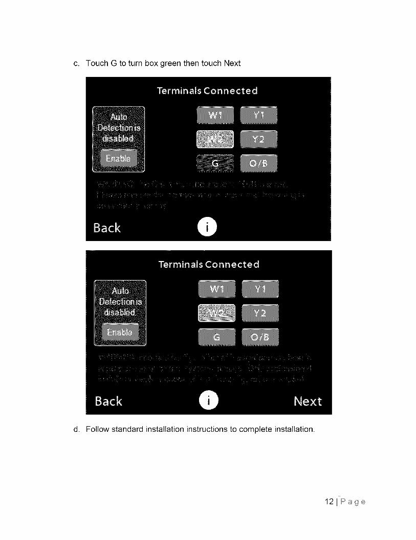
c. Touch G to turn box green then touch Next
d. Follow standard installation instructions to complete installation.
121Page
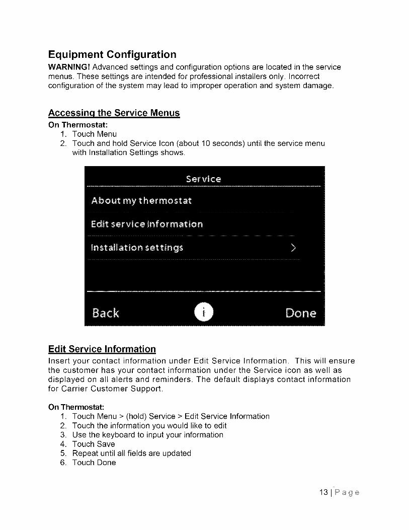
Equipment ConfigurationWARNING! Advanced settings and configuration options are located in the servicemenus. These settings are intended for professional installers only. Incorrectconfiguration of the system may lead to improper operation and system damage.
Accessing the Service MenusOn Thermostat:
1. Touch Menu
2. Touch and hold Service Icon (about 10 seconds) until the service menuwith Installation Settings shows.
Edit Service Information
Insert your contact information under Edit Service Information. This will ensurethe customer has your contact information under the Service icon as well asdisplayed on all alerts and reminders. The default displays contact informationfor Carrier Customer Support.
On Thermostat:
1. Touch Menu > (hold) Service > Edit Service Information2. Touch the information you would like to edit3. Use the keyboard to input your information4. Touch Save
5. Repeat until all fields are updated6. Touch Done
131Page
I nstallation Setti n,qs
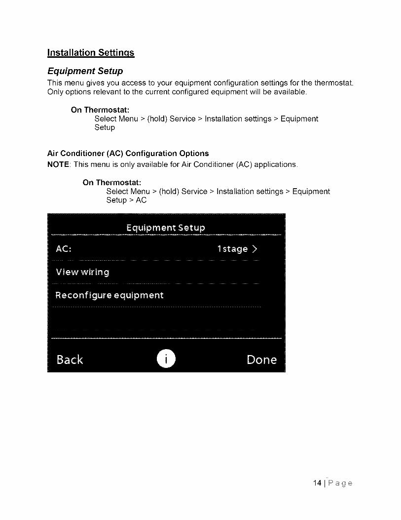
Equipment Setup
This menu gives you access to your equipment configuration settings for the thermostat.Only options relevant to the current configured equipment will be available.
On Thermostat:
Select Menu > (hold) Service > Installation settings > EquipmentSetup
Air Conditioner (AC) Configuration Options
NOTE: This menu is only available for Air Conditioner (AC) applications.
On Thermostat:
Select Menu > (hold) Service > Installation settings > EquipmentSetup > AC
141Page

Cooling Lockout
NOTE: An internet connection is required for this feature to operate properly.
Running the air conditioner below a certain temperature could cause damage tothe equipment. Enabling the feature will prevent the air conditioner from coolingwhen the outdoor temperature drops below 55°F. Consult your equipment's usermanuals to determine if it can be operated safely below 55°F.
• Default: Disabled
• Options: Enabled, Disabled
151Page
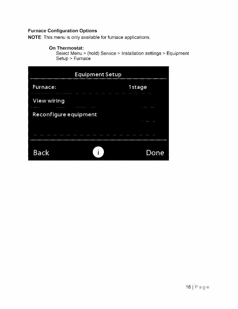
Furnace Configuration Options
NOTE: This menu is only available for furnace applications.
On Thermostat:
Select Menu > (hold) Service > Installation settings > EquipmentSetup > Furnace
161Page
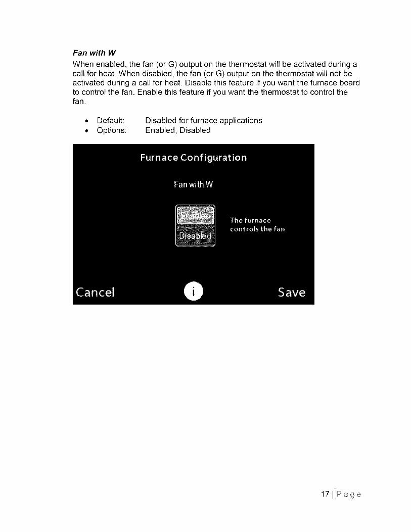
Fan with W
When enabled, the fan (or G) output on the thermostat will be activated during acall for heat. When disabled, the fan (or G) output on the thermostat will not beactivated during a call for heat. Disable this feature if you want the furnace boardto control the fan. Enable this feature if you want the thermostat to control thefan.
• Default:
• Options:Disabled for furnace applicationsEnabled, Disabled
171Page
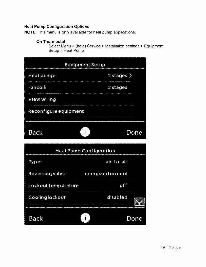
Heat Pump Configuration OptionsNOTE: This menu is only available for heat pump applications.
On Thermostat:Select Menu > (hold) Service > Installation settings > EquipmentSetup > Heat Pump
18JPage
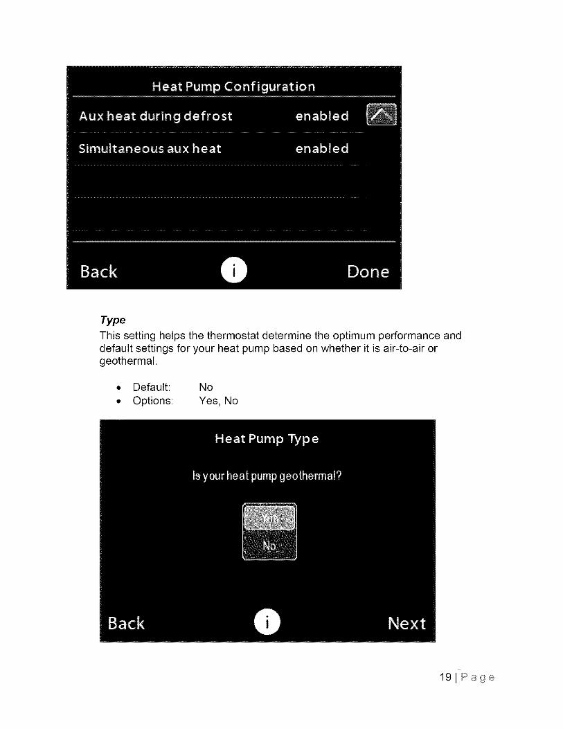
Type
This setting helps the thermostat determine the optimum performance anddefault settings for your heat pump based on whether it is air-to-air orgeothermal.
• Default: No
• Options: Yes, No
191Page
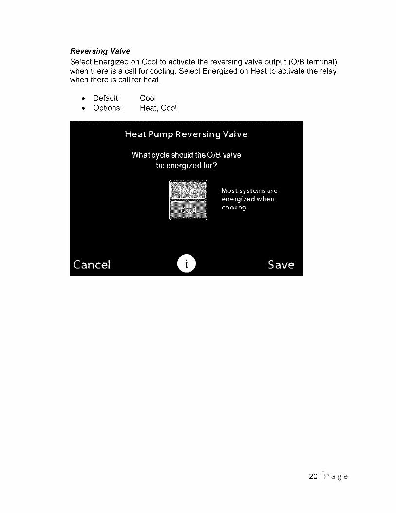
Reversing Valve
Select Energized on Cool to activate the reversing valve output (O/B terminal)when there is a call for cooling. Select Energized on Heat to activate the relaywhen there is call for heat.
• Default: Cool
• Options: Heat, Cool
20JPage

Lockout Temperature
NOTE: An internet connection is required for this feature to operate properly.When weather data is not available the thermostat will go through its normalstaging sequence of operation.
The heat pump lockout temperature can be used to force a switch from heatpump operation to auxiliary heating. When the outdoor temperature drops belowthis setting, the thermostat will stop using the heat pump for heating and only usethe auxiliary heat. This feature is especially useful for Hybrid Heat@ dual fuelapplications where the auxiliary heat source usually has a higher capacity thanthe heat pump at low temperature and can therefore help maintain comfort.
• Default:
• Options:
Off
Off, 5°F, IO°F, 15°F, 20°F, ..., 50°F, 55°F
21 J Page
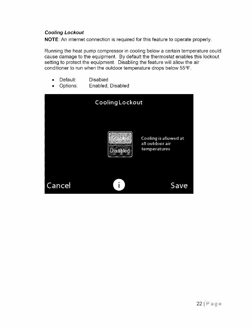
Cooling Lockout
NOTE: An internet connection is required for this feature to operate properly.
Running the heat pump compressor in cooling below a certain temperature couldcause damage to the equipment. By default the thermostat enables this lockoutsetting to protect the equipment. Disabling the feature will allow the airconditioner to run when the outdoor temperature drops below 55°F.
• Default: Disabled
• Options: Enabled, Disabled
22JPage
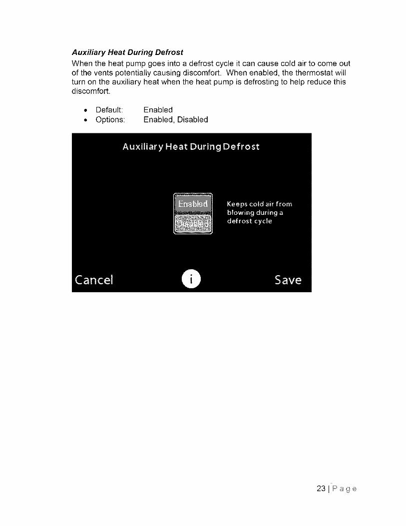
Auxiliary Heat During Defrost
When the heat pump goes into a defrost cycle it can cause cold air to come outof the vents potentially causing discomfort. When enabled, the thermostat willturn on the auxiliary heat when the heat pump is defrosting to help reduce thisdiscomfort.
• Default: Enabled
• Options: Enabled, Disabled
23JPage

Simultaneous Auxiliary Heat
When enabled, the thermostat will allow the auxiliary heat to be used at the sametime as the heat pump. The default value changes depending on the type ofauxiliary heating that is used. For non-dual fuel applications (electric resistanceauxiliary heating), the default setting is enabled. For dual fuel applications (fossilfuel auxiliary heating), the default setting is disabled.
Default:
Options:
Enabled for electric resistance auxiliary heating applicationsDisabled for Hybrid Heat ® dual fuel applications
Enabled, Disabled
NOTE: The auxiliary heating type is set and can only be changed in the GuidedSetup or reconfigure equipment processes.
241Page
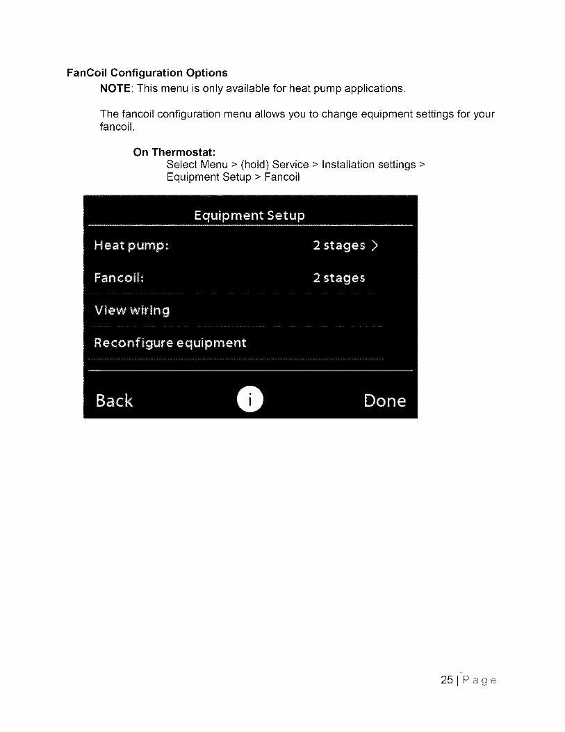
FanCoil Configuration OptionsNOTE: This menu is only available for heat pump applications.
The fancoil configuration menu allows you to change equipment settings for yourfancoil.
On Thermostat:Select Menu > (hold) Service > Installation settings >Equipment Setup > Fancoil
25JPage
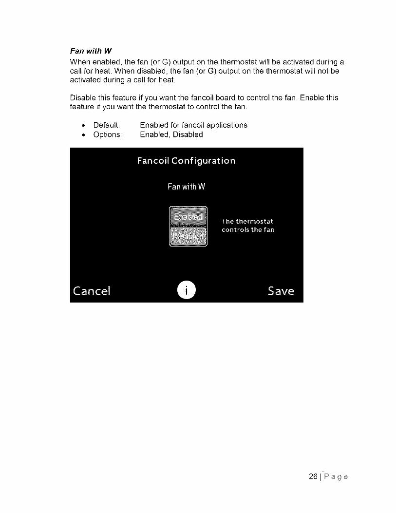
Fan with W
When enabled, the fan (or G) output on the thermostat will be activated during acall for heat. When disabled, the fan (or G) output on the thermostat will not beactivated during a call for heat.
Disable this feature if you want the fancoil board to control the fan. Enable thisfeature if you want the thermostat to control the fan.
• Default:
• Options:Enabled for fancoil applicationsEnabled, Disabled
26JPage
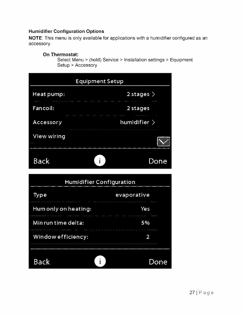
Humidifier Configuration OptionsNOTE: This menu is only available for applications with a humidifier configured as anaccessory.
On Thermostat:
Select Menu > (hold) Service > Installation settings > EquipmentSetup > Accessory
27JPage
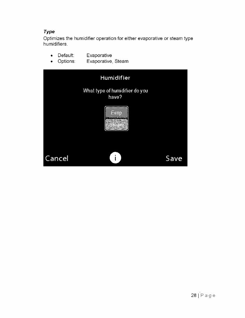
Type
Optimizes the humidifier operation for either evaporative or steam typehumidifiers.
• Default: Evaporative
• Options: Evaporative, Steam
281Page
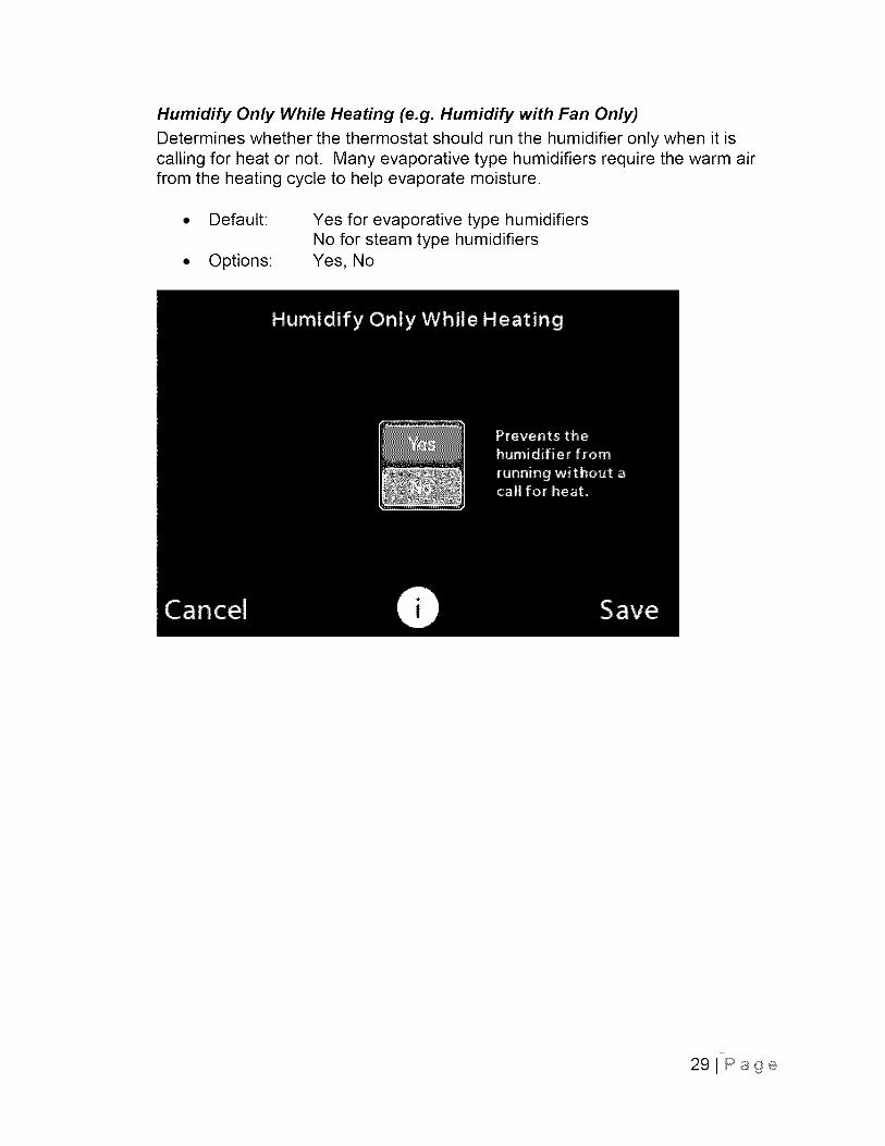
Humidify Only While Heating (e.g. Humidify with Fan Only)
Determines whether the thermostat should run the humidifier only when it iscalling for heat or not. Many evaporative type humidifiers require the warm airfrom the heating cycle to help evaporate moisture.
Default:
Options:
Yes for evaporative type humidifiersNo for steam type humidifiersYes, No
29JPage
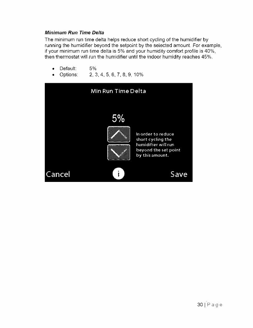
Minimum Run Time Delta
The minimum run time delta helps reduce short cycling of the humidifier byrunning the humidifier beyond the setpoint by the selected amount. For example,if your minimum run time delta is 5% and your humidity comfort profile is 40%,then thermostat will run the humidifier until the indoor humidity reaches 45%.
• Default: 5%
• Options: 2, 3, 4, 5, 6, 7, 8, 9, 10%
30JPage
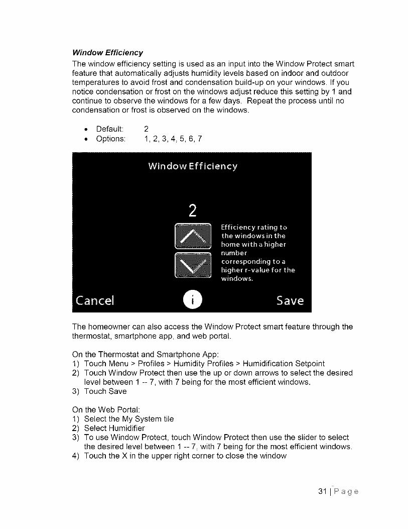
Window Efficiency
The window efficiency setting is used as an input into the Window Protect smartfeature that automatically adjusts humidity levels based on indoor and outdoortemperatures to avoid frost and condensation build-up on your windows. If younotice condensation or frost on the windows adjust reduce this setting by 1 andcontinue to observe the windows for a few days. Repeat the process until nocondensation or frost is observed on the windows.
• Default: 2
• Options: 1, 2, 3, 4, 5, 6, 7
The homeowner can also access the Window Protect smart feature through thethermostat, smartphone app, and web portal.
On the Thermostat and Smartphone App:1) Touch Menu > Profiles > Humidity Profiles > Humidification Setpoint2) Touch Window Protect then use the up or down arrows to select the desired
level between 1 -- 7, with 7 being for the most efficient windows.3) Touch Save
On the Web Portal:
1) Select the My System tile2) Select Humidifier3) To use Window Protect, touch Window Protect then use the slider to select
the desired level between 1 -- 7, with 7 being for the most efficient windows.4) Touch the X in the upper right corner to close the window
31 J Page
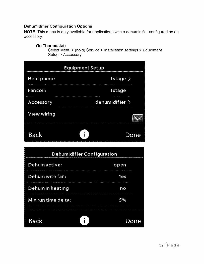
Dehumidifier Configuration OptionsNOTE: This menu is only available for applications with a dehumidifier configured as anaccessory.
On Thermostat:
Select Menu > (hold) Service > Installation settings > EquipmentSetup > Accessory
32JPage
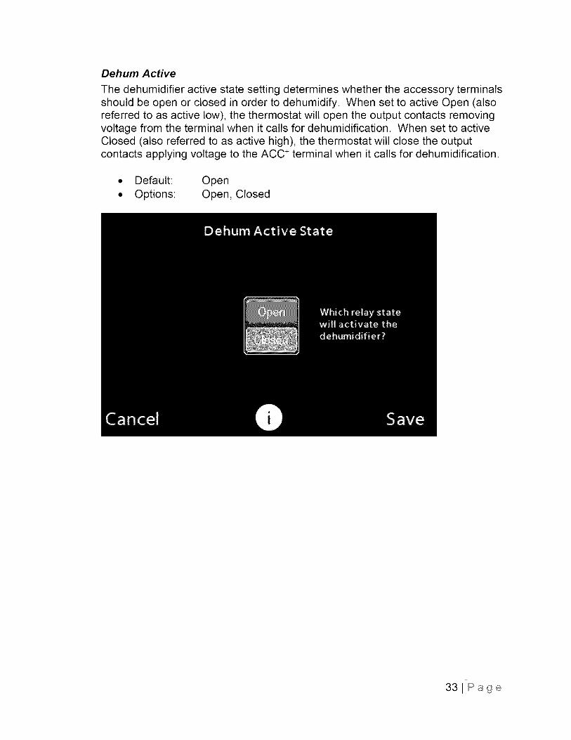
Dehum Active
The dehumidifier active state setting determines whether the accessory terminalsshould be open or closed in order to dehumidify. When set to active Open (alsoreferred to as active low), the thermostat will open the output contacts removingvoltage from the terminal when it calls for dehumidification. When set to activeClosed (also referred to as active high), the thermostat will close the outputcontacts applying voltage to the ACC ÷ terminal when it calls for dehumidification.
• Default: Open• Options: Open, Closed
33JPage
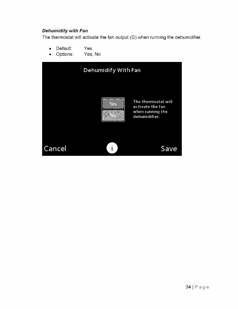
Dehumidify with Fan
The thermostat will activate the fan output (G) when running the dehumidifier.
• Default: Yes
• Options: Yes, No
341Page
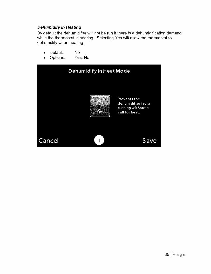
Dehumidify in Heating
By default the dehumidifier will not be run if there is a dehumidification demandwhile the thermostat is heating. Selecting Yes will allow the thermostat todehumidify when heating.
• Default: No
• Options: Yes, No
351Page
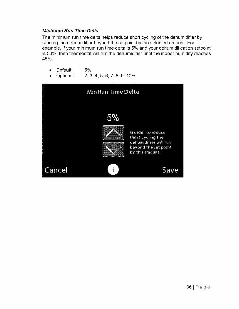
Minimum Run Time Delta
The minimum run time delta helps reduce short cycling of the dehumidifier byrunning the dehumidifier beyond the setpoint by the selected amount. Forexample, if your minimum run time delta is 5% and your dehumidification setpointis 50%, then thermostat will run the dehumidifier until the indoor humidity reaches45%.
• Default: 5%
• Options: 2, 3, 4, 5, 6, 7, 8, 9, 10%
36JPage
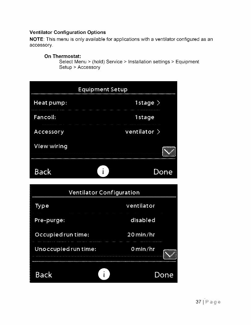
Ventilator Configuration OptionsNOTE: This menu is only available for applications with a ventilator configured as anaccessory.
On Thermostat:
Select Menu > (hold) Service > Installation settings > EquipmentSetup > Accessory
371Page
38J Page
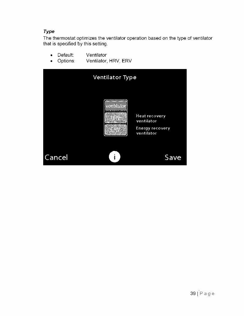
Type
The thermostat optimizes the ventilator operation based on the type of ventilatorthat is specified by this setting.
• Default: Ventilator
• Options: Ventilator, HRV, ERV
39JPage
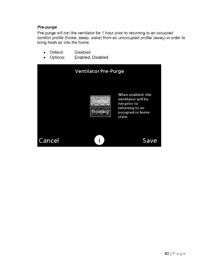
Pre-purge
Pre-purge will run the ventilator for 1 hour prior to returning to an occupiedcomfort profile (home, sleep, wake) from an unoccupied profile (away) in order tobring fresh air into the home.
• Default: Disabled
• Options: Enabled, Disabled
40lPage
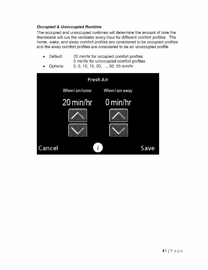
Occupied & Unoccupied Runtime
The occupied and unoccupied runtimes will determine the amount of time thethermostat will run the ventilator every hour for different comfort profiles. Thehome, wake, and sleep comfort profiles are considered to be occupied profilesand the away comfort profiles are considered to be an unoccupied profile.
Default:
Options:
20 min/hr for occupied comfort profiles0 min/hr for unoccupied comfort profiles0, 5, 10, 15, 20, ..., 50, 55 min/hr
41 J Page

Free Cooling Enable
NOTE: This menu is not available for heat recovery (HRV) or energy recoveryventilator (ERV) types.
Free cooling takes advantage of the outdoor weather conditions to provide tohelp cool your home without using your AC or heat pump. When the outdoorconditions are right, the thermostat will use the ventilator to bring in outdoor air tocool your home.
• Default: Enabled
• Options Enabled, Disabled
421Page
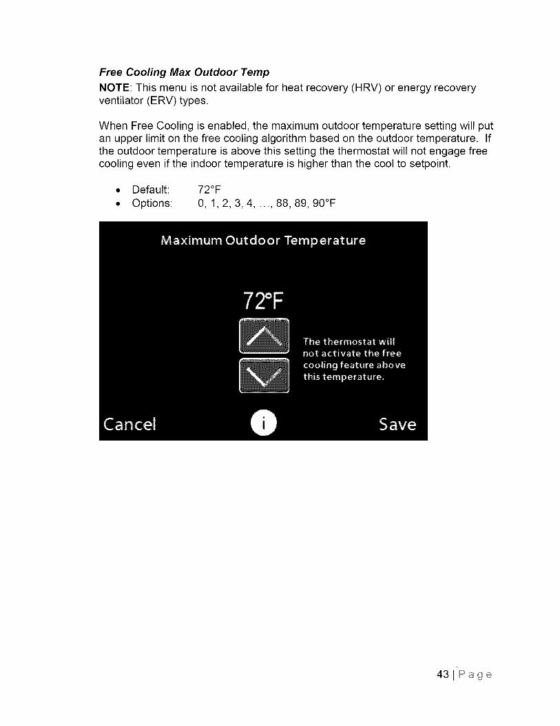
Free Cooling Max Outdoor Temp
NOTE: This menu is not available for heat recovery (HRV) or energy recoveryventilator (ERV) types.
When Free Cooling is enabled, the maximum outdoor temperature setting will putan upper limit on the free cooling algorithm based on the outdoor temperature. Ifthe outdoor temperature is above this setting the thermostat will not engage freecooling even if the indoor temperature is higher than the cool to setpoint.
• Default:
• Options:
72°F
0, 1, 2, 3, 4, ..., 88, 89, 90°F
431Page

Free Cooling Max Outdoor Humidity
NOTE: This menu is not available for heat recovery (HRV) or energy recoveryventilator (ERV) types.
When Free Cooling is enabled, the maximum outdoor humidity setting will put anupper limit on the free cooling algorithm based on the outdoor humidity. If theoutdoor humidity level is above this setting the thermostat will not engage freecooling even if the indoor temperature is higher than the cool to setpoint.
• Default:
• Options:
Off
Off, 5, 10, 15, 20,..., 90, 95%
441Page
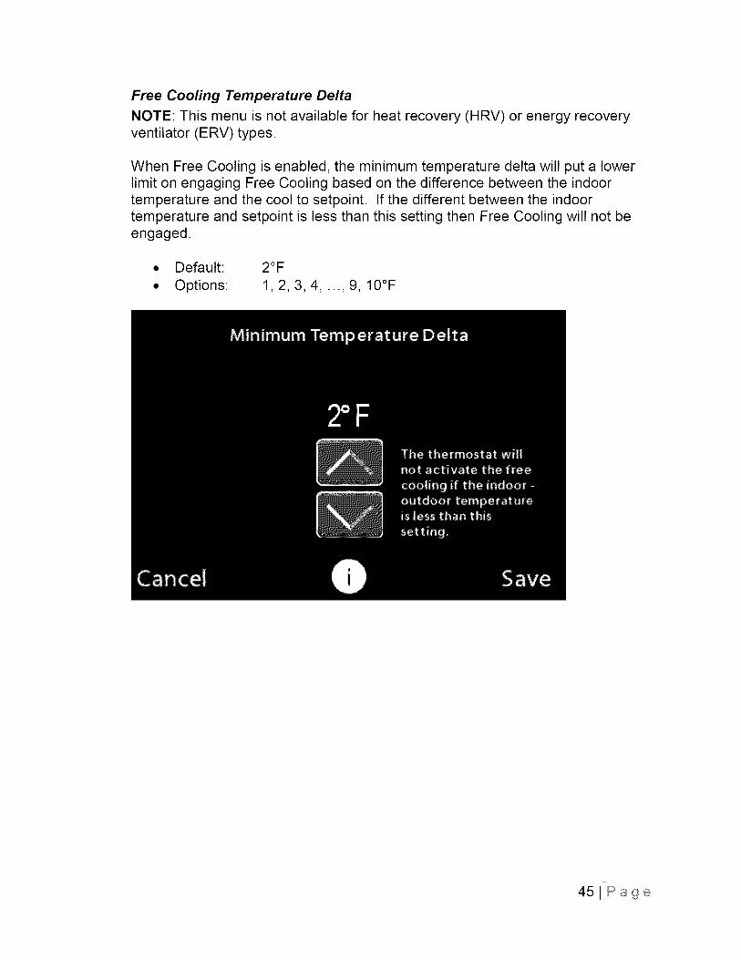
Free Cooling Temperature Delta
NOTE: This menu is not available for heat recovery (HRV) or energy recoveryventilator (ERV) types.
When Free Cooling is enabled, the minimum temperature delta will put a lowerlimit on engaging Free Cooling based on the difference between the indoortemperature and the cool to setpoint. If the different between the indoortemperature and setpoint is less than this setting then Free Cooling will not beengaged.
• Default: 2°F
• Options: 1, 2, 3, 4, ..., 9, 10°F
451Page
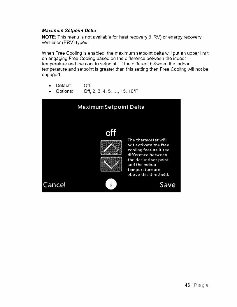
Maximum Setpoint Delta
NOTE: This menu is not available for heat recovery (HRV) or energy recoveryventilator (ERV) types.
When Free Cooling is enabled, the maximum setpoint delta will put an upper limiton engaging Free Cooling based on the difference between the indoortemperature and the cool to setpoint. If the different between the indoortemperature and setpoint is greater than this setting then Free Cooling will not beengaged.
• Default: Off
• Options: Off, 2, 3, 4, 5, ..., 15, 16°F
461Page
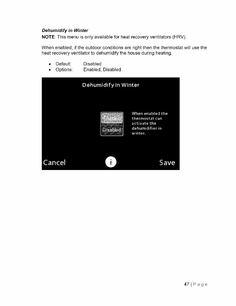
Dehumidify in Winter
NOTE: This menu is only available for heat recovery ventilators (HRV).
When enabled, if the outdoor conditions are right then the thermostat will use theheat recovery ventilator to dehumidify the house during heating.
• Default: Disabled
• Options: Enabled, Disabled
471Page
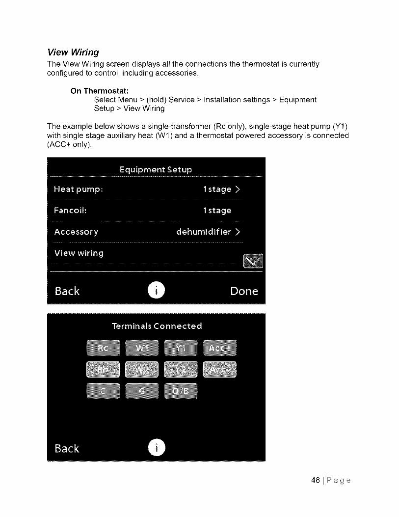
View WiringThe View Wiring screen displays all the connections the thermostat is currentlyconfigured to control, including accessories.
On Thermostat:
Select Menu > (hold) Service > Installation settings > EquipmentSetup > View Wiring
The example below shows a single-transformer (Rc only), single-stage heat pump (Y1)with single stage auxiliary heat (Wl) and a thermostat powered accessory is connected(ACC+ only).
481Page
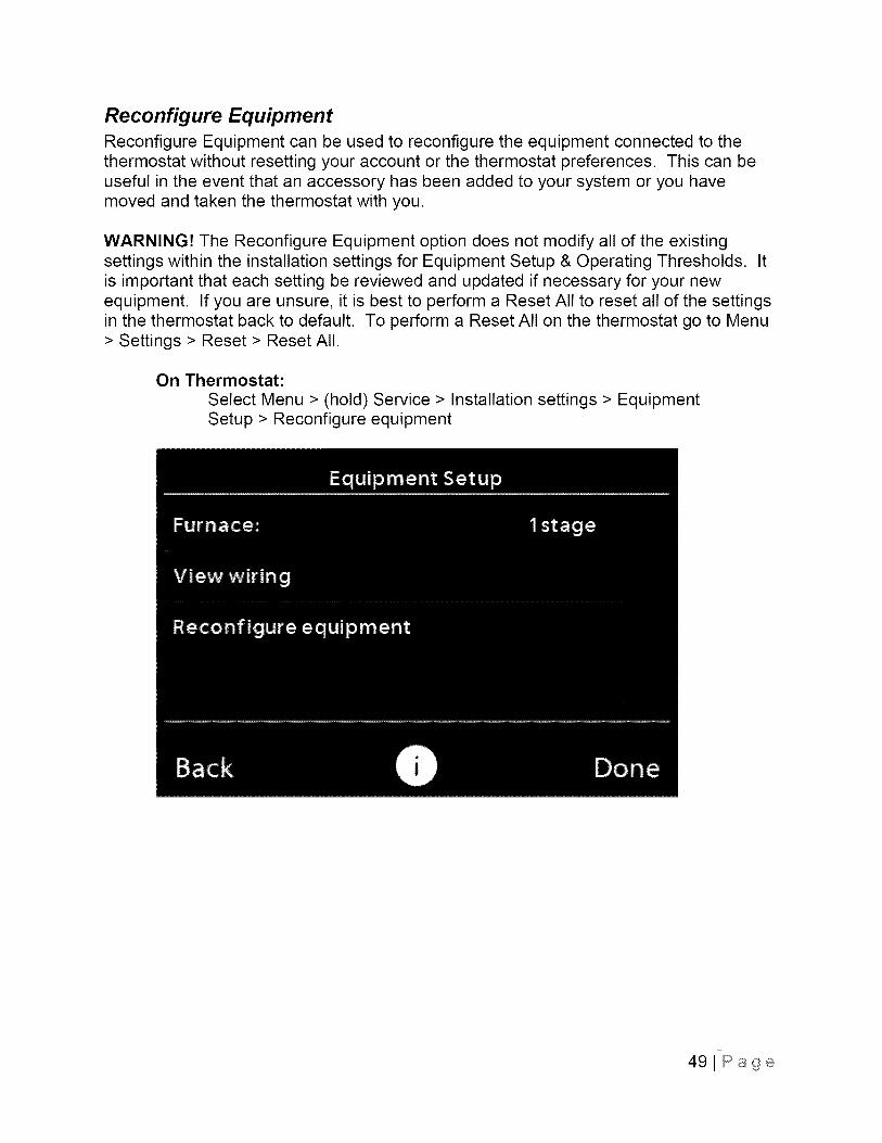
Reconfigure EquipmentReconfigure Equipment can be used to reconfigure the equipment connected to thethermostat without resetting your account or the thermostat preferences. This can beuseful in the event that an accessory has been added to your system or you havemoved and taken the thermostat with you.
WARNING! The Reconfigure Equipment option does not modify all of the existingsettings within the installation settings for Equipment Setup & Operating Thresholds. Itis important that each setting be reviewed and updated if necessary for your newequipment. If you are unsure, it is best to perform a Reset All to reset all of the settingsin the thermostat back to default. To perform a Reset All on the thermostat go to Menu> Settings > Reset > Reset All.
On Thermostat:
Select Menu > (hold) Service > Installation settings > EquipmentSetup > Reconfigure equipment
491Page
50JPage
Thresholds
This menu lets you configure the temperature and time thresholds associated with theheating and cooling equipment's sequence of operation. You must configure EquipmentSetup before setting the thresholds. Depending on your system's equipment, not alloptions may be available.
On Thermostat:
Select Menu > (hold) Service > Installation Settings > OperatingThresholds
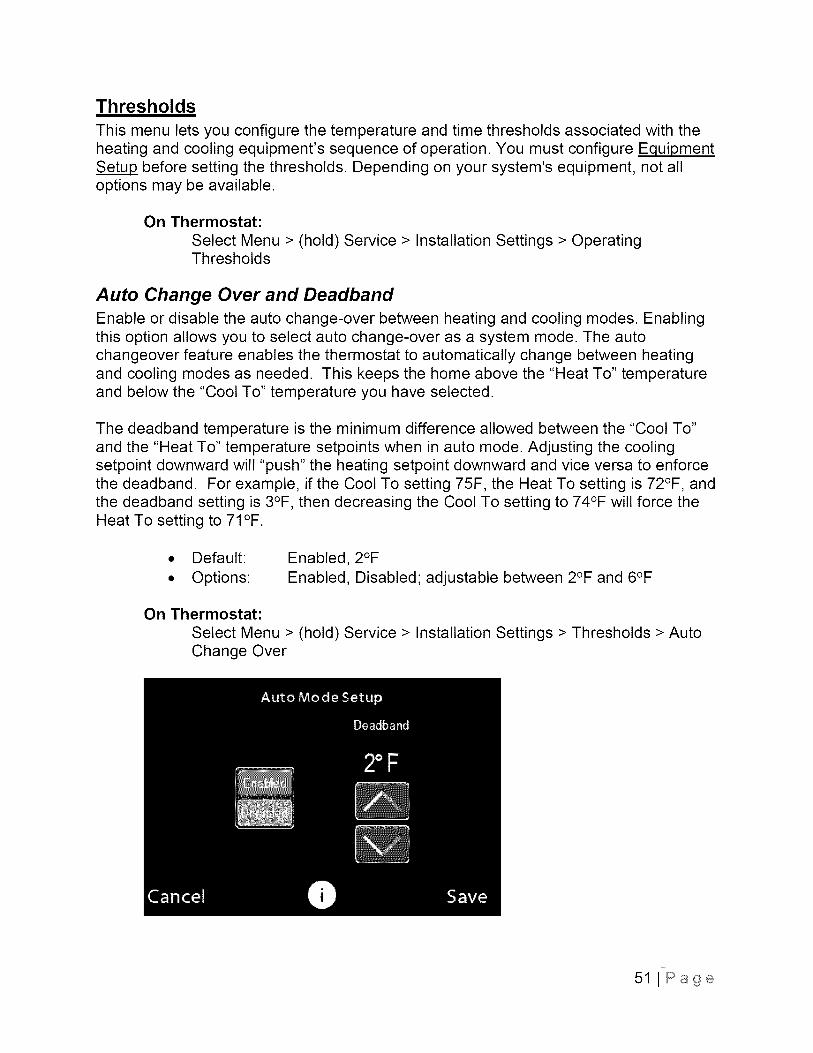
Auto Change Over and DeadbandEnable or disable the auto change-over between heating and cooling modes. Enablingthis option allows you to select auto change-over as a system mode. The autochangeover feature enables the thermostat to automatically change between heatingand cooling modes as needed. This keeps the home above the "Heat To" temperatureand below the "Cool To" temperature you have selected.
The deadband temperature is the minimum difference allowed between the "Cool To"and the "Heat To" temperature setpoints when in auto mode. Adjusting the coolingsetpoint downward will "push" the heating setpoint downward and vice versa to enforcethe deadband. For example, if the Cool To setting 75F, the Heat To setting is 72°F, andthe deadband setting is 3°F, then decreasing the Cool To setting to 74°F will force theHeat To setting to 71 °F.
• Default:
• Options:
Enabled, 2°F
Enabled, Disabled; adjustable between 2°F and 6°F
On Thermostat:
Select Menu > (hold) Service > Installation Settings > Thresholds > AutoChange Over
51 I Page
Compressor Configurations
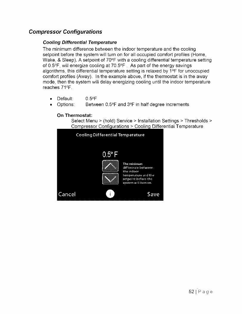
Cooling Differential Temperature
The minimum difference between the indoor temperature and the coolingsetpoint before the system will turn on for all occupied comfort profiles (Home,Wake, & Sleep). A setpoint of 70°F with a cooling differential temperature settingof 0.5°F, will energize cooling at 70.5°F. As part of the energy savingsalgorithms, this differential temperature setting is relaxed by I°F for unoccupiedcomfort profiles (Away). In the example above, if the thermostat is in the awaymode, then the system will delay energizing cooling until the indoor temperaturereaches 71°F.
Default:
Options:
0.5°F
Between 0.5°F and 3°F in half degree increments
On Thermostat:
Select Menu > (hold) Service > Installation Settings > Thresholds >Com Confi urations > Coolin Differential Temperature
521Page
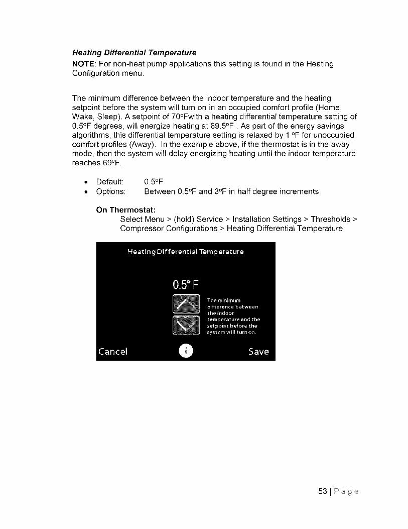
Heating Differential Temperature
NOTE: For non-heat pump applications this setting is found in the HeatingConfiguration menu.
The minimum difference between the indoor temperature and the heatingsetpoint before the system will turn on in an occupied comfort profile (Home,Wake, Sleep). A setpoint of 70°Fwith a heating differential temperature setting of0.5°F degrees, will energize heating at 69.5°F. As part of the energy savingsalgorithms, this differential temperature setting is relaxed by 1 °F for unoccupiedcomfort profiles (Away). In the example above, if the thermostat is in the awaymode, then the system will delay energizing heating until the indoor temperaturereaches 69°F.
Default:
Options:
0.5°F
Between 0.5°F and 3°F in half degree increments
On Thermostat:
Select Menu > (hold) Service > Installation Settings > Thresholds >Compressor Configurations > Heating Differential Temperature
531Page
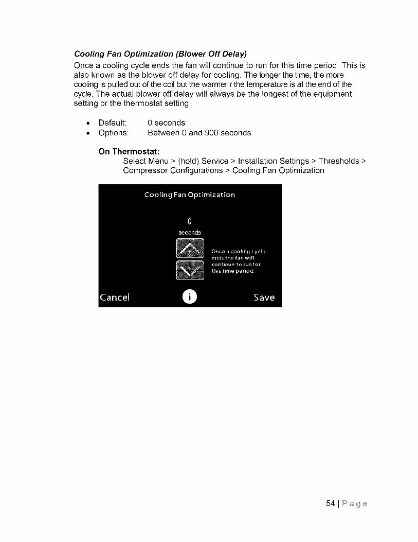
Cooling Fan Optimization (Blower Off Delay)
Once a cooling cycle ends the fan will continue to run for this time period. This isalso known as the blower off delay for cooling. The longer the time, the morecooling is pulled out of the coil but the warmer r the temperature is at the end of thecycle. The actual blower off delay will always be the longest of the equipmentsetting or the thermostat setting.
• Default:
• Options:
0 seconds
Between 0 and 900 seconds
On Thermostat:
Select Menu > (hold) Service > Installation Settings > Thresholds >Compressor Configurations > Cooling Fan Optimization
541Page
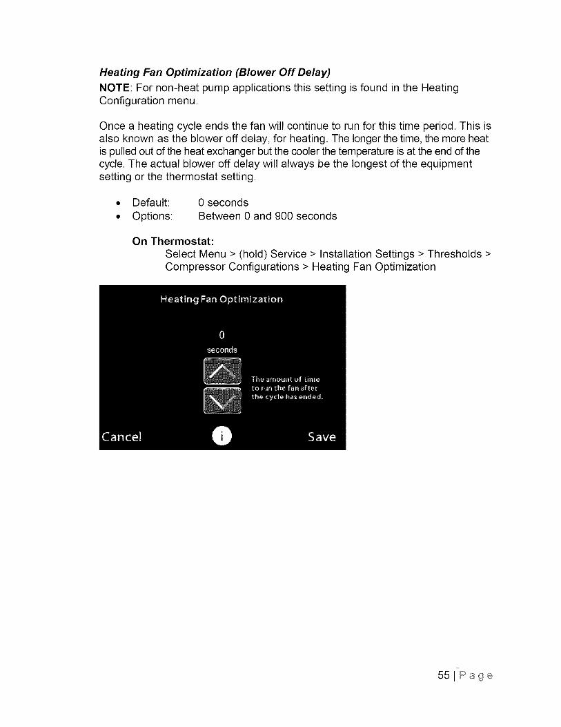
Heating Fan Optimization (Blower Off Delay)
NOTE: For non-heat pump applications this setting is found in the HeatingConfiguration menu.
Once a heating cycle ends the fan will continue to run for this time period. This isalso known as the blower off delay, for heating. The longer the time, the more heatis pulled out of the heat exchanger but the cooler the temperature is at the end of thecycle. The actual blower off delay will always be the longest of the equipmentsetting or the thermostat setting.
• Default:
• Options:
0 seconds
Between 0 and 900 seconds
On Thermostat:
Select Menu > (hold) Service > Installation Settings > Thresholds >Compressor Configurations > Heating Fan Optimization
551Page
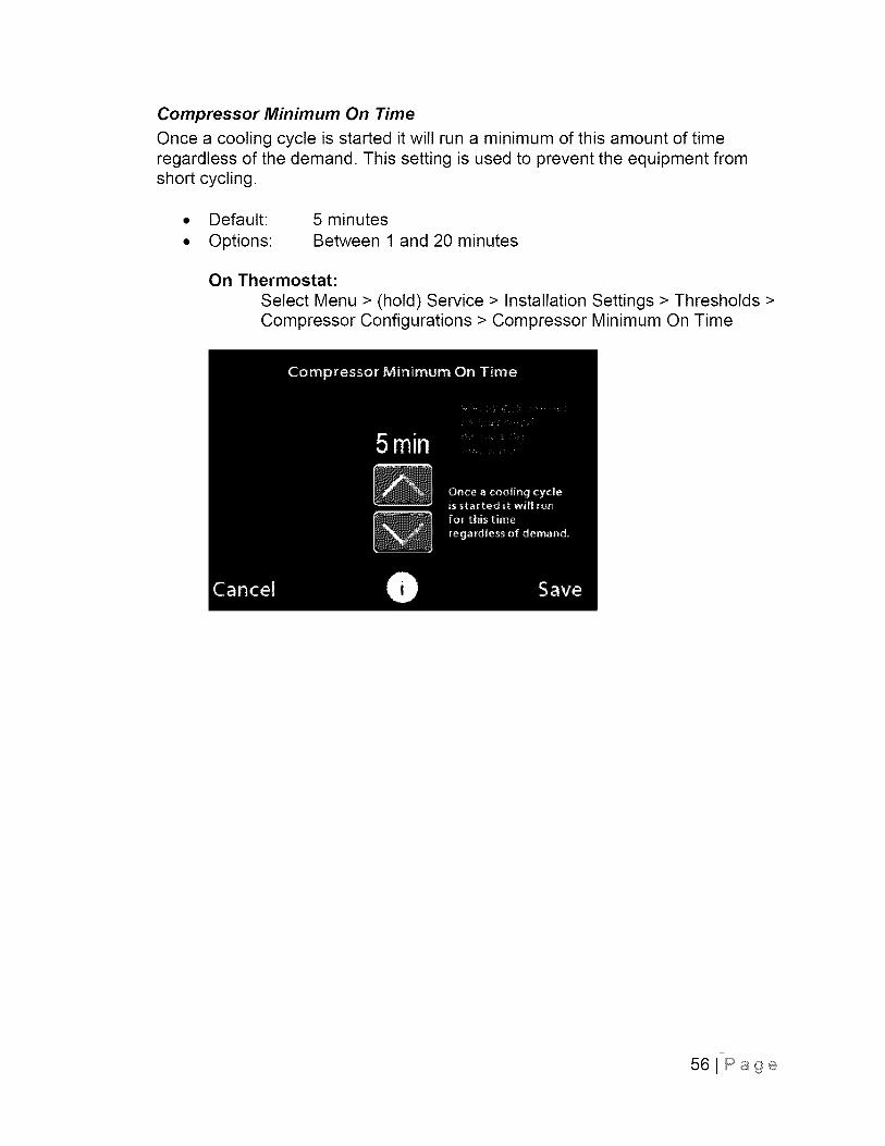
Compressor Minimum On Time
Once a cooling cycle is started it will run a minimum of this amount of timeregardless of the demand. This setting is used to prevent the equipment fromshort cycling.
• Default:
• Options:
5 minutes
Between 1 and 20 minutes
On Thermostat:
Select Menu > (hold) Service > Installation Settings > Thresholds >Compressor Configurations > Compressor Minimum On Time
56iPage
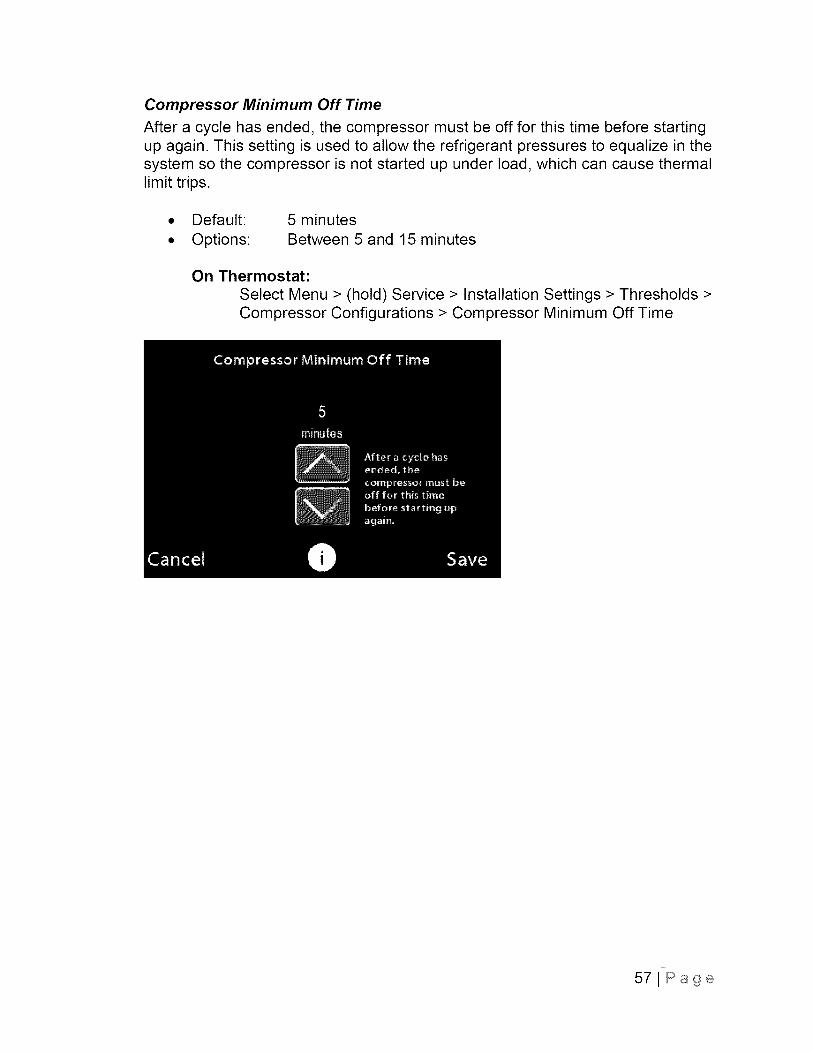
Compressor Minimum Off Time
After a cycle has ended, the compressor must be off for this time before startingup again. This setting is used to allow the refrigerant pressures to equalize in thesystem so the compressor is not started up under load, which can cause thermallimit trips.
• Default:
• Options:
5 minutes
Between 5 and 15 minutes
On Thermostat:
Select Menu > (hold) Service > Installation Settings > Thresholds >Compressor Configurations > Compressor Minimum Off Time
57JPage

Compressor Reverse Staging
When enabled, the thermostat can go from stage 2 to stage 1 as it approachessetpoint. This setting allows the compressor to run longer cycles at stage 1 forgreater efficiency. If it is desired that the system not switch back and forth fromstage 1 to stage 2 then back the stage 1 before turning off, this setting should bedisabled.
Default: Disabled
Options: Enabled, Disabled
On Thermostat:
Select Menu > (hold) Service > Installation Settings > Thresholds >Compressor Configurations > Compressor reverse staging
58JPage
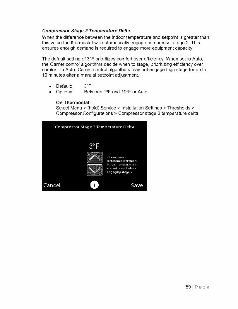
Compressor Stage 2 Temperature Delta
When the difference between the indoor temperature and setpoint is greater thanthis value the thermostat will automatically engage compressor stage 2. Thisensures enough demand is required to engage more equipment capacity.
The default setting of 3°F prioritizes comfort over efficiency. When set to Auto,the Carrier control algorithms decide when to stage, prioritizing efficiency overcomfort. In Auto, Carrier control algorithms may not engage high stage for up to10 minutes after a manual setpoint adjustment.
• Default:
• Options:
3OF
Between I°F and 10°F or Auto
On Thermostat:
Select Menu > (hold) Service > Installation Settings > Thresholds >Compressor Configurations > Compressor stage 2 temperature delta
59JPage
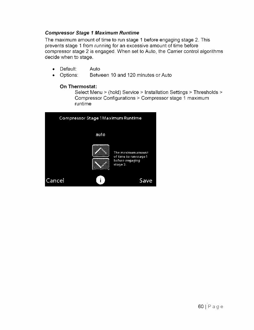
Compressor Stage 1 Maximum Runtime
The maximum amount of time to run stage 1 before engaging stage 2. Thisprevents stage 1 from running for an excessive amount of time beforecompressor stage 2 is engaged. When set to Auto, the Carrier control algorithmsdecide when to stage.
• Default:
• Options:
Auto
Between 10 and 120 minutes or Auto
On Thermostat:
Select Menu > (hold) Service > Installation Settings > Thresholds >Compressor Configurations > Compressor stage 1 maximumruntime
60JPage
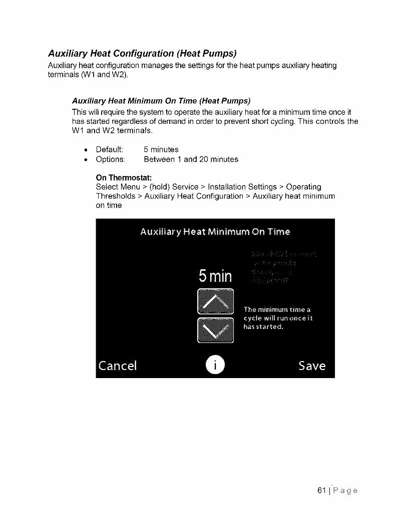
Auxiliary Heat Configuration (Heat Pumps)Auxiliary heat configuration manages the settings for the heat pumps auxiliary heatingterminals (W1 and W2).
Auxiliary Heat Minimum On Time (Heat Pumps)
This will require the system to operate the auxiliary heat for a minimum time once ithas started regardless of demand in order to prevent short cycling. This controls theW1 and W2 terminals.
Default: 5 minutes
Options: Between 1 and 20 minutes
On Thermostat:
Select Menu > (hold) Service > Installation Settings > OperatingThresholds > Auxiliary Heat Configuration > Auxiliary heat minimumon time
61 J Page
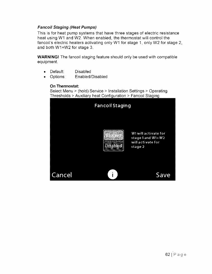
Fancoil Staging (Heat Pumps)
This is for heat pump systems that have three stages of electric resistanceheat using W1 and W2. When enabled, the thermostat will control thefancoil's electric heaters activating only W1 for stage 1, only W2 for stage 2,and both WI+W2 for stage 3.
WARNING! The fancoil staging feature should only be used with compatibleequipment.
• Default: Disabled
• Options: Enabled/Disabled
On Thermostat:
Select Menu > (hold) Service > Installation Settings > OperatingThresholds > Auxiliary heat Configuration > Fancoil Staging
62JPage
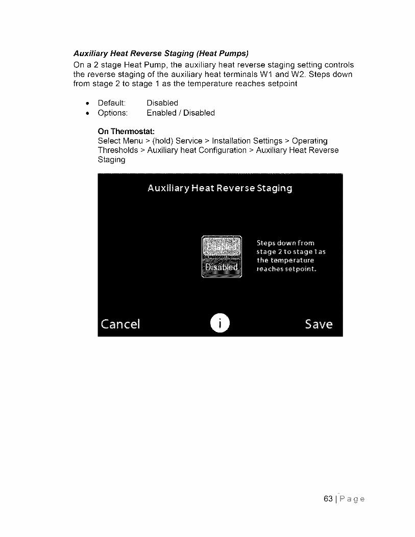
Auxiliary Heat Reverse Staging (Heat Pumps)
On a 2 stage Heat Pump, the auxiliary heat reverse staging setting controlsthe reverse staging of the auxiliary heat terminals W1 and W2. Steps downfrom stage 2 to stage 1 as the temperature reaches setpoint
• Default: Disabled
• Options: Enabled / Disabled
On Thermostat:
Select Menu > (hold) Service > Installation Settings > OperatingThresholds > Auxiliary heat Configuration > Auxiliary Heat ReverseStaging
63JPage
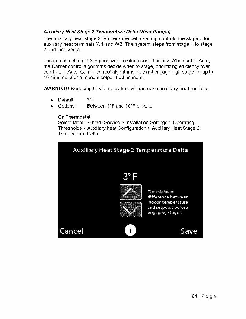
Auxiliary Heat Stage 2 Temperature Delta (Heat Pumps)
The auxiliary heat stage 2 temperature delta setting controls the staging forauxiliary heat terminals Wl and W2. The system steps from stage 1 to stage2 and vice versa.
The default setting of 3°F prioritizes comfort over efficiency. When set to Auto,the Carrier control algorithms decide when to stage, prioritizing efficiency overcomfort. In Auto, Carrier control algorithms may not engage high stage for up to10 minutes after a manual setpoint adjustment.
WARNING! Reducing this temperature will increase auxiliary heat run time.
• Default:
• Options:
3OFBetween I°F and 10°F or Auto
On Thermostat:
Select Menu > (hold) Service > Installation Settings > OperatingThresholds > Auxiliary heat Configuration > Auxiliary Heat Stage 2Temperature Delta
641Page
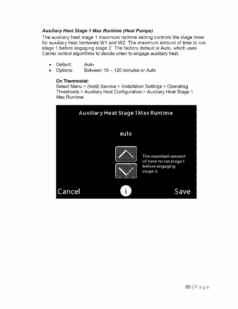
Auxiliary Heat Stage 1 Max Runtime (Heat Pumps)
The auxiliary heat stage 1 maximum runtime setting controls the stage timerfor auxiliary heat terminals W1 and W2. The maximum amount of time to runstage 1 before engaging stage 2. The factory default is Auto, which usesCarrier control algorithms to decide when to engage auxiliary heat.
• Default:
• Options:
Auto
Between 10 - 120 minutes or Auto
On Thermostat:
Select Menu > (hold) Service > Installation Settings > OperatingThresholds > Auxiliary heat Configuration > Auxiliary Heat Stage 1Max Runtime
651Page
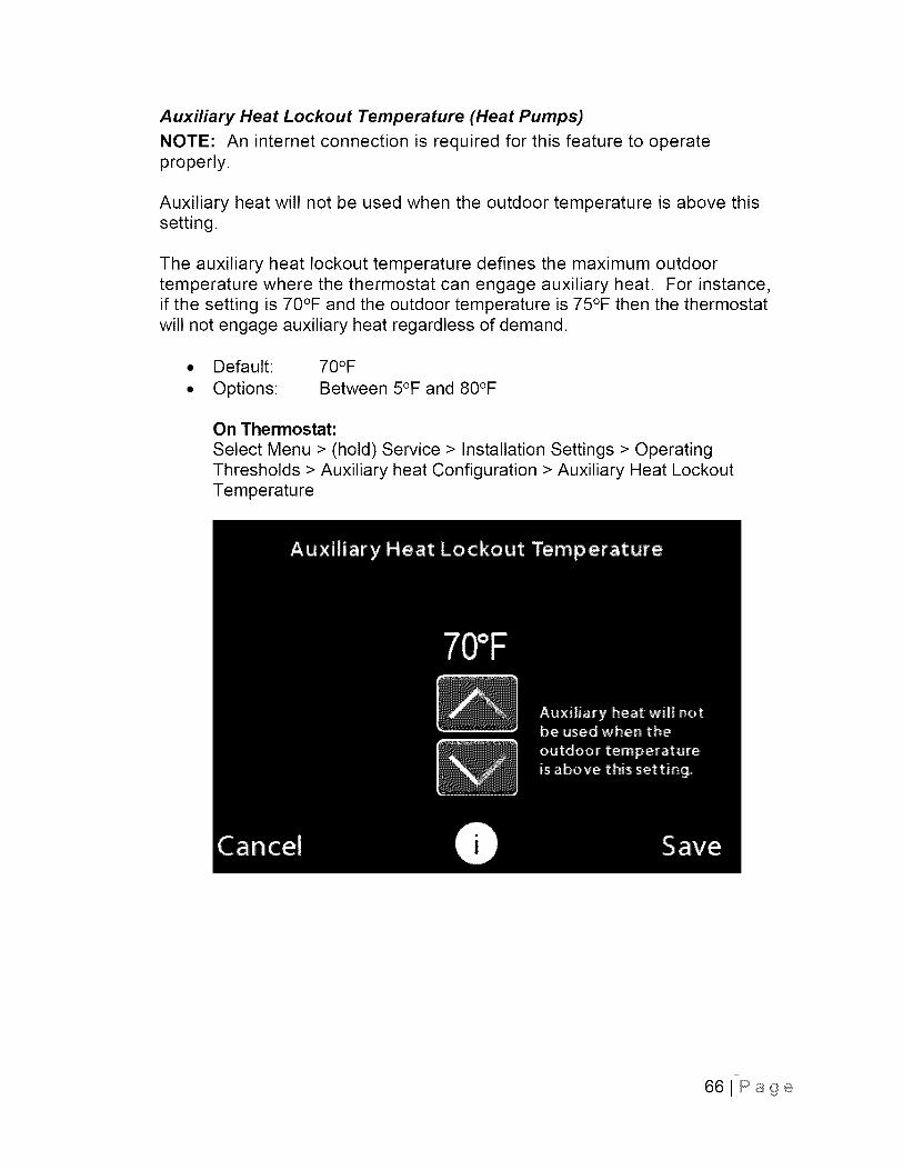
Auxiliary Heat Lockout Temperature (Heat Pumps)
NOTE: An internet connection is required for this feature to operateproperly.
Auxiliary heat will not be used when the outdoor temperature is above thissetting.
The auxiliary heat lockout temperature defines the maximum outdoortemperature where the thermostat can engage auxiliary heat. For instance,if the setting is 70°F and the outdoor temperature is 75°F then the thermostatwill not engage auxiliary heat regardless of demand.
• Default: 70°F
• Options: Between 5°F and 80°F
On Thermostat:
Select Menu > (hold) Service > Installation Settings > OperatingThresholds > Auxiliary heat Configuration > Auxiliary Heat LockoutTemperature
661Page
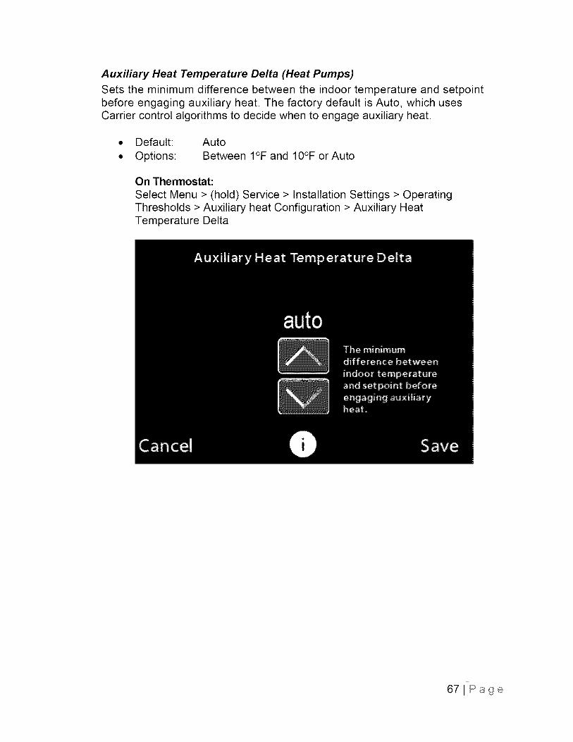
Auxiliary Heat Temperature Delta (Heat Pumps)
Sets the minimum difference between the indoor temperature and setpointbefore engaging auxiliary heat. The factory default is Auto, which usesCarrier control algorithms to decide when to engage auxiliary heat.
• Default:
• Options:
Auto
Between I°F and IO°F or Auto
On Thermostat:
Select Menu > (hold) Service > Installation Settings > OperatingThresholds > Auxiliary heat Configuration > Auxiliary HeatTemperature Delta
67JPage
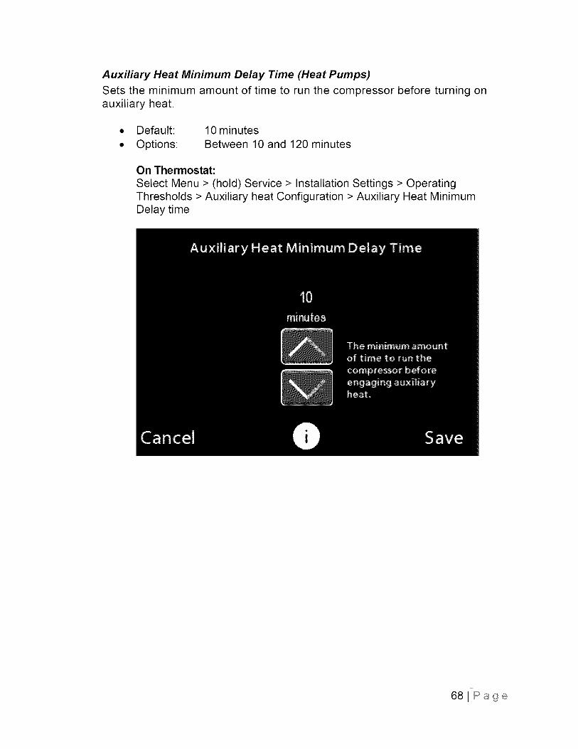
Auxiliary Heat Minimum Delay Time (Heat Pumps)
Sets the minimum amount of time to run the compressor before turning onauxiliary heat.
• Default:
• Options:
10 minutes
Between 10 and 120 minutes
On Thermostat:
Select Menu > (hold) Service > Installation Settings > OperatingThresholds > Auxiliary heat Configuration > Auxiliary Heat MinimumDelay time
68JPage
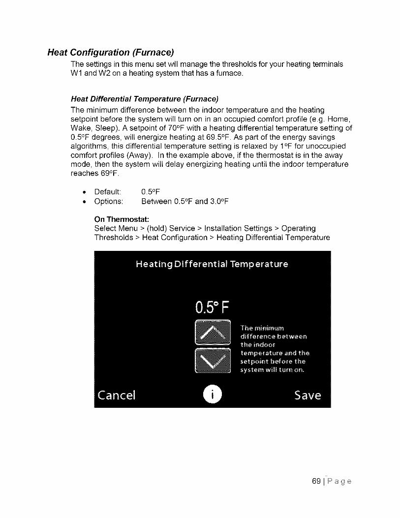
Heat Configuration (Furnace)The settings in this menu set will manage the thresholds for your heating terminalsWl and W2 on a heating system that has a furnace.
Heat Differential Temperature (Furnace)
The minimum difference between the indoor temperature and the heatingsetpoint before the system will turn on in an occupied comfort profile (e.g. Home,Wake, Sleep). A setpoint of 70°F with a heating differential temperature setting of0.5°F degrees, will energize heating at 69.5°F. As part of the energy savingsalgorithms, this differential temperature setting is relaxed by I°F for unoccupiedcomfort profiles (Away). In the example above, if the thermostat is in the awaymode, then the system will delay energizing heating until the indoor temperaturereaches 69°F.
Default:
Options:
0.5°FBetween 0.5°F and 3.0°F
On Thermostat:
Select Menu > (hold) Service > Installation Settings > OperatingThresholds > Heat Configuration > Heating Differential Temperature
69JPage
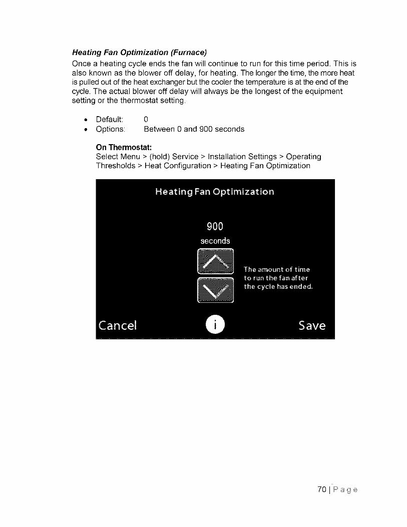
Heating Fan Optimization (Furnace)
Once a heating cycle ends the fan will continue to run for this time period. This isalso known as the blower off delay, for heating. The longer the time, the more heatis pulled out of the heat exchanger but the cooler the temperature is at the end of thecycle. The actual blower off delay will always be the longest of the equipmentsetting or the thermostat setting.
• Default: 0
• Options: Between 0 and 900 seconds
On Thermostat:
Select Menu > (hold) Service > Installation Settings > OperatingThresholds > Heat Configuration > Heating Fan Optimization
70JPage
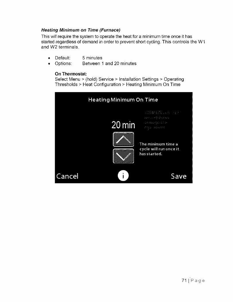
Heating Minimum on Time (Furnace)
This will require the system to operate the heat for a minimum time once it hasstarted regardless of demand in order to prevent short cycling. This controls the W1and W2 terminals.
Default:
Options:
5 minutes
Between 1 and 20 minutes
On Thermostat:
Select Menu > (hold) Service > Installation Settings > OperatingThresholds > Heat Configuration > Heating Minimum On Time
71 J Page
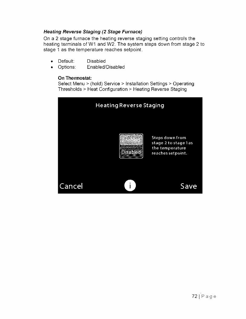
Heating Reverse Staging (2 Stage Furnace)
On a 2 stage furnace the heating reverse staging setting controls theheating terminals of W1 and W2. The system steps down from stage 2 tostage 1 as the temperature reaches setpoint.
• Default: Disabled
• Options: Enabled/Disabled
On Thermostat:
Select Menu > (hold) Service > Installation Settings > OperatingThresholds > Heat Configuration > Heating Reverse Staging
72JPage
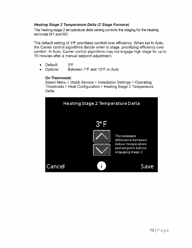
Heating Stage 2 Temperature Delta (2 Stage Furnace)
The heating stage 2 temperature delta setting controls the staging for the heatingterminals Wl and W2.
The default setting of 3°F prioritizes comfort over efficiency. When set to Auto,the Carrier control algorithms decide when to stage, prioritizing efficiency overcomfort. In Auto, Carrier control algorithms may not engage high stage for up to10 minutes after a manual setpoint adjustment.
• Default:
• Options:
3°FBetween I°F and 10°F or Auto
On Thermostat:
Select Menu > (hold) Service > Installation Settings > OperatingThresholds > Heat Configuration > Heating Stage 2 TemperatureDelta
73JPage

Heating Stage 1 Maximum Runtime (2 Stage Furnace)
The stage 1 maximum runtime setting controls the stage time for the heatingterminals W1 and W2. When set to Auto, the Carrier control algorithms decidewhen to stage.
• Default:
• Options:
Auto
Between 10 and 120 minutes or Auto
On Thermostat:
Select Menu > (hold) Service > Installation Settings > OperatingThresholds > Heat Configuration > Heating Stage 1 MaximumRuntime
741Page
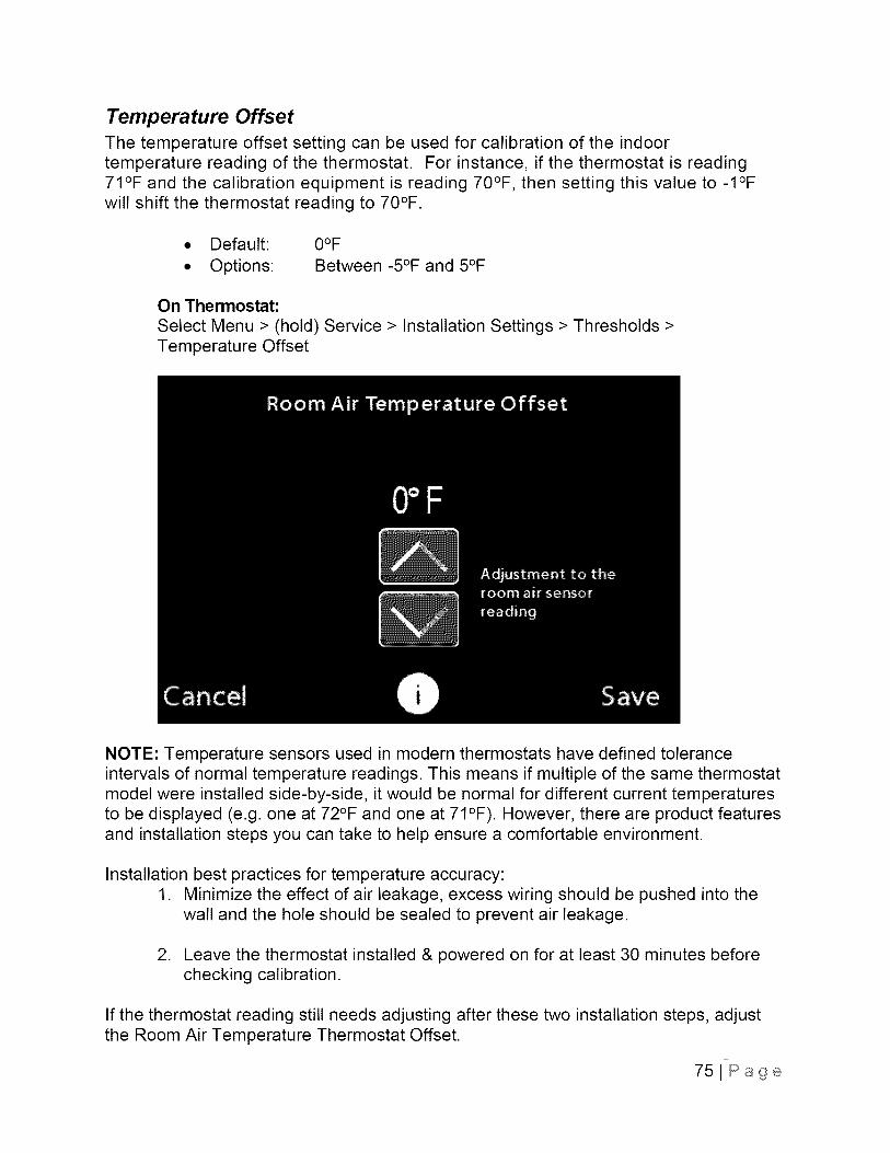
Temperature OffsetThe temperature offset setting can be used for calibration of the indoortemperature reading of the thermostat. For instance, if the thermostat is reading71°F and the calibration equipment is reading 70°F, then setting this value to -I°Fwill shift the thermostat reading to 70°F.
• Default: O°F
• Options: Between -5°F and 5°F
On Thermostat:
Select Menu > (hold) Service > Installation Settings > Thresholds >Temperature Offset
NOTE: Temperature sensors used in modern thermostats have defined toleranceintervals of normal temperature readings. This means if multiple of the same thermostatmodel were installed side-by-side, it would be normal for different current temperaturesto be displayed (e.g. one at 72°F and one at 71°F). However, there are product featuresand installation steps you can take to help ensure a comfortable environment.
Installation best practices for temperature accuracy:1. Minimize the effect of air leakage, excess wiring should be pushed into the
wall and the hole should be sealed to prevent air leakage.
2. Leave the thermostat installed & powered on for at least 30 minutes beforechecking calibration.
If the thermostat reading still needs adjusting after these two installation steps, adjustthe Room Air Temperature Thermostat Offset.
75JPage
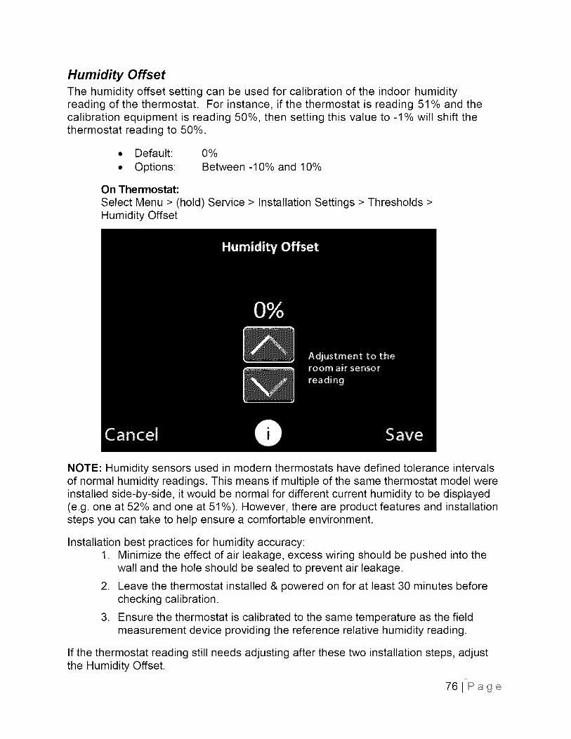
Humidity OffsetThe humidity offset setting can be used for calibration of the indoor humidityreading of the thermostat. For instance, if the thermostat is reading 51% and thecalibration equipment is reading 50%, then setting this value to -1% will shift thethermostat reading to 50%.
• Default: 0%
• Options: Between -10% and 10%
On Thermostat:
Select Menu > (hold) Service > Installation Settings > Thresholds >Humidity Offset
NOTE: Humidity sensors used in modern thermostats have defined tolerance intervalsof normal humidity readings. This means if multiple of the same thermostat model wereinstalled side-by-side, it would be normal for different current humidity to be displayed(e.g. one at 52% and one at 51%). However, there are product features and installationsteps you can take to help ensure a comfortable environment.
Installation best practices for humidity accuracy:1. Minimize the effect of air leakage, excess wiring should be pushed into the
wall and the hole should be sealed to prevent air leakage.
2. Leave the thermostat installed & powered on for at least 30 minutes beforechecking calibration.
3. Ensure the thermostat is calibrated to the same temperature as the fieldmeasurement device providing the reference relative humidity reading.
If the thermostat reading still needs adjusting after these two installation steps, adjustthe Humidity Offset.
761Page
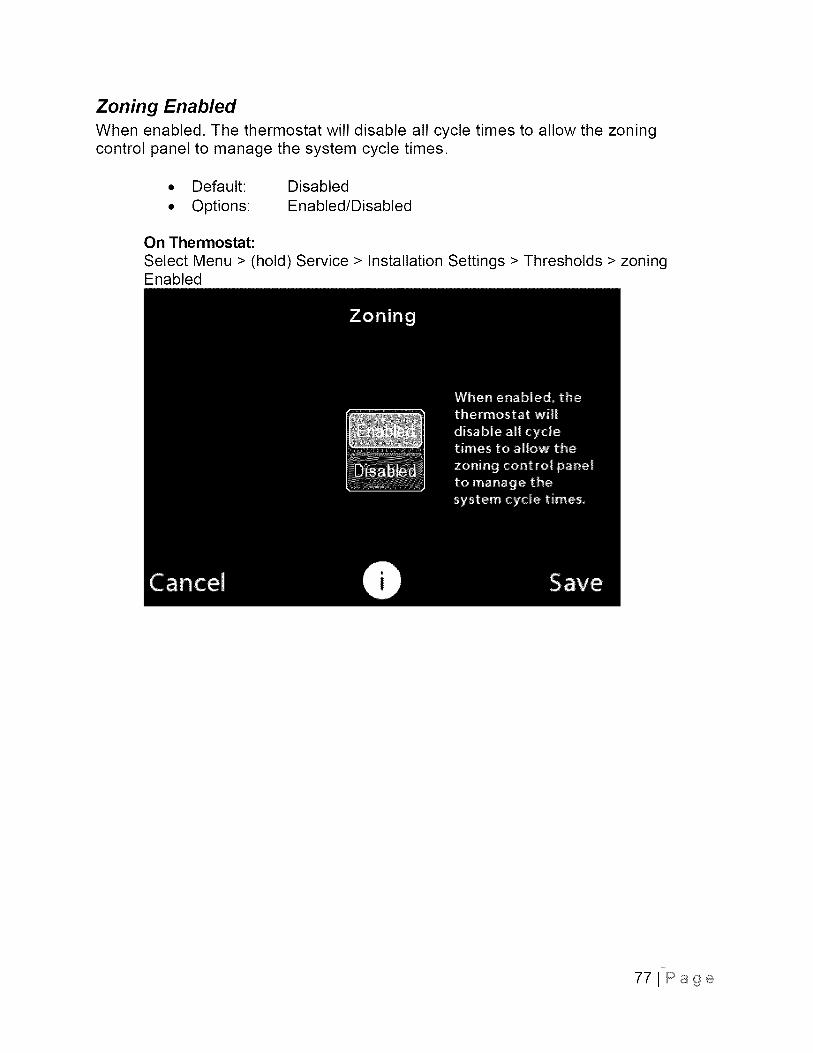
Zoning EnabledWhen enabled. The thermostat will disable all cycle times to allow the zoningcontrol panel to manage the system cycle times.
• Default: Disabled
• Options: Enabled/Disabled
On Thermostat:
Select Menu > (hold) Service > Installation Settings > Thresholds > zoningEnabled
771Page
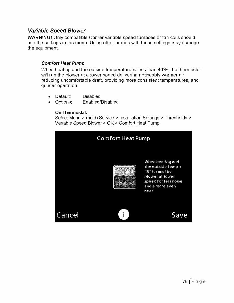
Variable Speed BlowerWARNING! Only compatible Carrier variable speed furnaces or fan coils shoulduse the settings in the menu. Using other brands with these settings may damagethe equipment.
Comfort Heat Pump
When heating and the outside temperature is less than 40°F, the thermostatwill run the blower at a lower speed delivering noticeably warmer air,reducing uncomfortable draft, providing more consistent temperatures, andquieter operation.
• Default: Disabled
• Options: Enabled/Disabled
On Thermostat:
Select Menu > (hold) Service > Installation Settings > Thresholds >Variable Speed Blower > OK > Comfort Heat Pump
78JPage
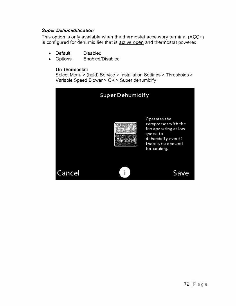
Super Dehumidification
This option is only available when the thermostat accessory terminal (ACC+)is configured for dehumidifier that is active open and thermostat powered.
• Default: Disabled
• Options: Enabled/Disabled
On Thermostat:
Select Menu > (hold) Service > Installation Settings > Thresholds >Variable Speed Blower > OK > Super dehumidify
79JPage
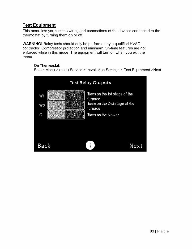
Test EquipmentThis menu lets you test the wiring and connections of the devices connected to thethermostat by turning them on or off.
WARNING! Relay tests should only be performed by a qualified HVACcontractor. Compressor protection and minimum run-time features are notenforced while in this mode. The equipment will turn off when you exit themenu.
On Thermostat:
Select Menu > (hold) Service > Installation Settings > Test Equipment >Next
80lPage
Dehumidification Options
Dehumidification Options for Most Cooling Equipment
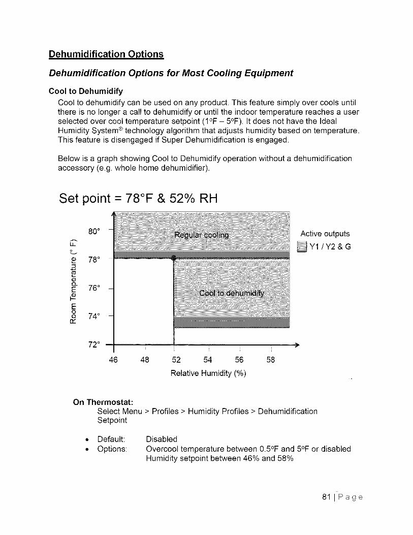
Cool to Dehumidify
Cool to dehumidify can be used on any product. This feature simply over cools untilthere is no longer a call to dehumidify or until the indoor temperature reaches a userselected over cool temperature setpoint (I°F - 5°F). It does not have the IdealHumidity System ® technology algorithm that adjusts humidity based on temperature.This feature is disengaged if Super Dehumidification is engaged.
Below is a graph showing Cool to Dehumidify operation without a dehumidificationaccessory (e.g. whole home dehumidifier).
Set point- 78°F & 52% RH
80 °
ii
e 78 °::3
IL
E 76°
E0o 74 °
n,"
72 ° I I I ......................>
46 48 52 54 56 58
Relative Humidity (%)
Active outputs
On Thermostat:
Select Menu > Profiles > Humidity Profiles > DehumidificationSetpoint
Default:
Options:
Disabled
Overcool temperature between 0.5°F and 5°F or disabledHumidity setpoint between 46% and 58%
81 I Page
Dehumidification Options with Variable Speed Carrier EquipmentNOTE: See below for capable equipment.
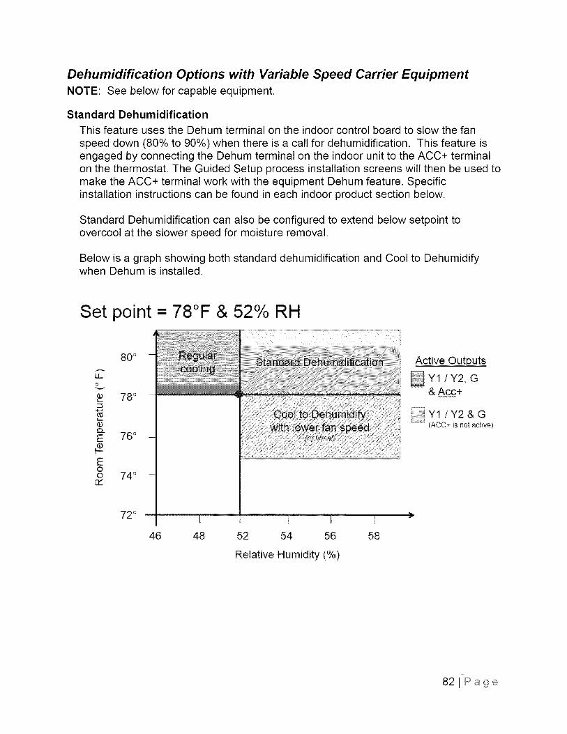
Standard Dehumidification
This feature uses the Dehum terminal on the indoor control board to slow the fan
speed down (80% to 90%) when there is a call for dehumidification. This feature isengaged by connecting the Dehum terminal on the indoor unit to the ACC+ terminalon the thermostat. The Guided Setup process installation screens will then be used tomake the ACC+ terminal work with the equipment Dehum feature. Specificinstallation instructions can be found in each indoor product section below.
Standard Dehumidification can also be configured to extend below setpoint toovercool at the slower speed for moisture removal.
Below is a graph showing both standard dehumidification and Cool to Dehumidifywhen Dehum is installed.
Set point = 78°F & 52% RH
80 °
LL
78 °
E 76°
E0o 74 °rY
72 °il [ Ii I_
46 48 52 54 56 58
Relative Humidity (%)
Active Outputs
Y1/Y2, G& Ac£+
::::::j Y1 /Y2 & G(ACC+ Js not adive)
)
821Page
Ideal Humidity System ® Technology(Standard Dehumidification + Super Dehumidification)
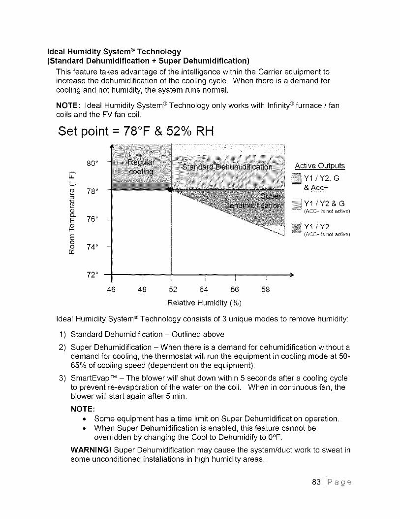
This feature takes advantage of the intelligence within the Carrier equipment toincrease the dehumidification of the cooling cycle. When there is a demand forcooling and not humidity, the system runs normal.
NOTE: Ideal Humidity System ® Technology only works with Infinity ® furnace / fancoils and the FV fan coil.
Set point = 78°F & 52% RH
80 °
LL
78 °
o_E 76o#E0o 74 °rY
72 ° ii i I, I_
46 48 52 54 56 58
Active Outputs
Yt/Y2, G& Ac£+
Y1/Y2 & G(ACC+ is not active)
%(ACC+ is not active)
Relative Humidity (%)
Ideal Humidity System ® Technology consists of 3 unique modes to remove humidity:
1)
2)
3)
Standard Dehumidification -Outlined above
Super Dehumidification - When there is a demand for dehumidification without ademand for cooling, the thermostat will run the equipment in cooling mode at 50-65% of cooling speed (dependent on the equipment).
SmartEvap TM - The blower will shut down within 5 seconds after a cooling cycleto prevent re-evaporation of the water on the coil. When in continuous fan, theblower will start again after 5 min.
NOTE:
• Some equipment has a time limit on Super Dehumidification operation.
• When Super Dehumidification is enabled, this feature cannot beoverridden by changing the Cool to Dehumidify to 0°F.
WARNING! Super Dehumidification may cause the system/duct work to sweat insome unconditioned installations in high humidity areas.
83JPage
Ideal Humidity System ® Technology with FK/FV Fan CoilsStandard Dehumidification: When there is a call for cooling and a call fordehumidification, the fan coil delivers airflow which is approximately 80% of the nominalcooling airflow to increase the latent capacity of the system.
Super Dehumidification: When there is no call for cooling but a call fordehumidification, airflow is reduced to 50% of the cooling airflow set up and the unit isautomatically set to overcool up to 3°F.
The blower delay needs to be set to zero off delay to prevent re-evaporation of thewater on the coil. It is advisable to always set the off delay to zero and allow thethermostat to control the off delay.
Set up Ideal Humidity System + Technoloqy on an FK/FV fan coil:
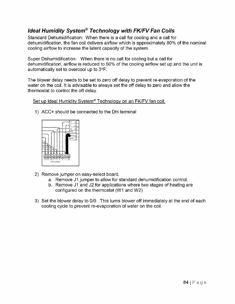
1) ACC+ should be connected to the DH terminal
2)
3)
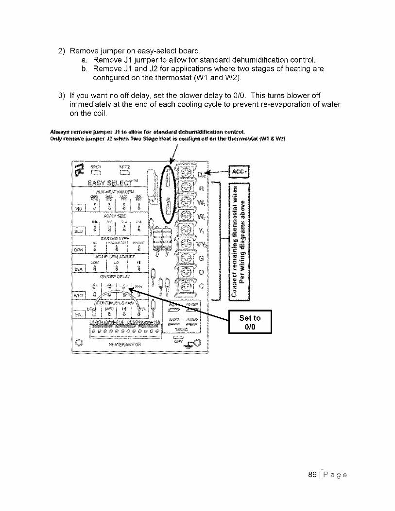
Remove jumper on easy-select board.a. Remove J1 jumper to allow for standard dehumidification control.b. Remove J1 and J2 for applications where two stages of heating are
configured on the thermostat (W1 and W2).
Set the blower delay to 0/0. This turns blower off immediately at the end of eachcooling cycle to prevent re-evaporation of water on the coil.
841Page
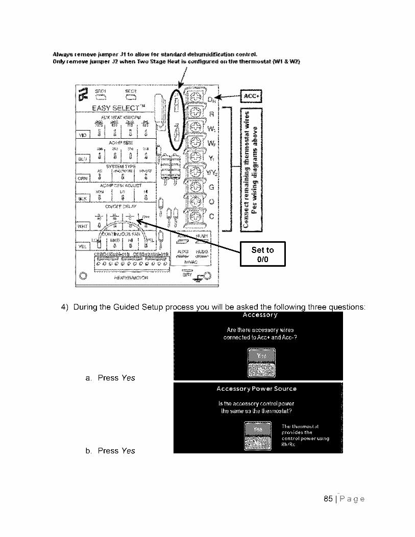
AIw_ remove jumper Jl to allow for standard dehumid_c_iofl co.tel,On_ reme_e j.mper J2 when Two Stage He_ is configured o. the thermest_ C_ & _)
m
o
_w_
m
4) During the Guided Setup process you will be asked the following three questions:
a. Press Yes
b. Press Yes
851Page
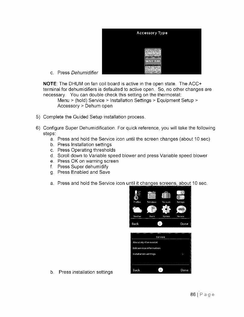
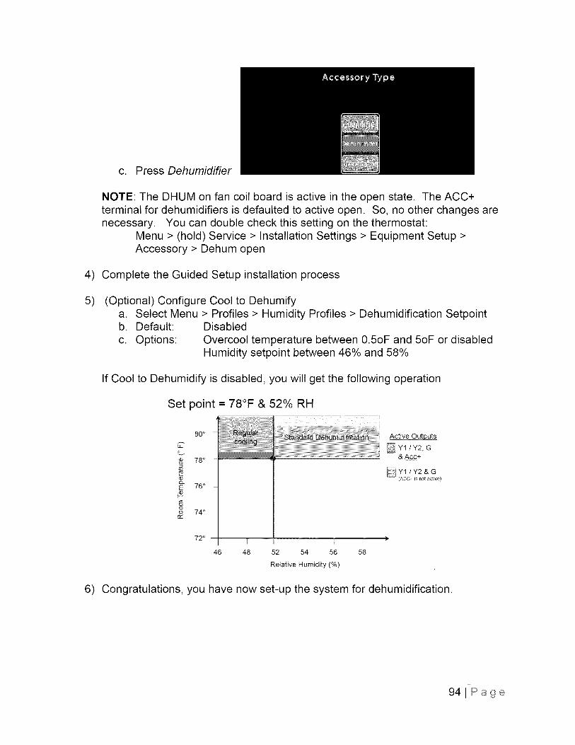
c. Press Dehumidifier
NOTE: The DHUM on fan coil board is active in the open state. The ACC+terminal for dehumidifiers is defaulted to active open. So, no other changes arenecessary. You can double check this setting on the thermostat:
Menu > (hold) Service > Installation Settings > Equipment Setup >Accessory > Dehum open
5) Complete the Guided Setup installation process.
6) Configure Super Dehumidification. For quick reference, you will take the followingsteps:
a. Pressb. Pressc. Pressd. Scrolle. Pressf. Press
g. Press
and hold the Service icon until the screen changes (about 10 sec)Installation settingsOperating thresholdsdown to Variable speed blower and press Variable speed blowerOK on warning screenSuper dehumidifyEnabled and Save
a. Press and hold the Service icon until it changes screens, about 10 sec.
b. Press installation settings
861Page
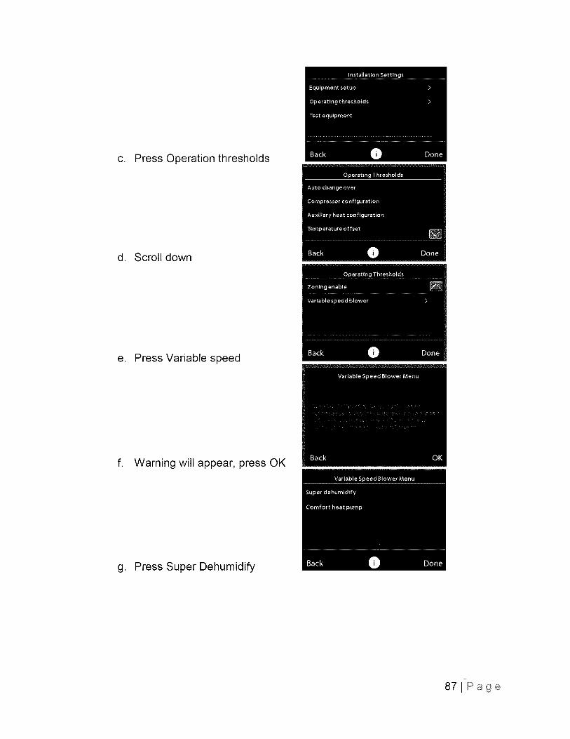
c. Press Operation thresholds
d. Scroll down
e. Press Variable speed
f. Warning will appear, press OK
g. Press Super Dehumidify
87JPage
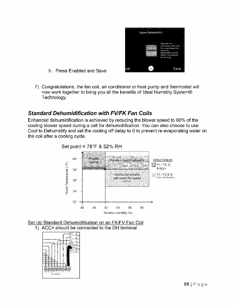
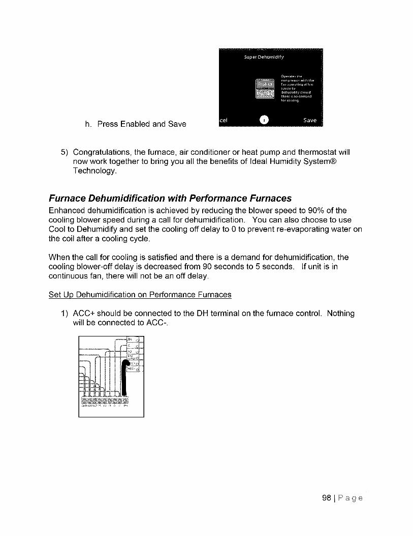
h. Press Enabled and Save
7) Congratulations, the fan coil, air conditioner or heat pump and thermostat willnow work together to bring you all the benefits of Ideal Humidity System®Technology.
Standard Dehumidification with FV/FK Fan Coils
Enhanced dehumidification is achieved by reducing the blower speed to 80% of thecooling blower speed during a call for dehumidification. You can also choose to useCool to Dehumidify and set the cooling off delay to 0 to prevent re-evaporating water onthe coil after a cooling cycle.
Set point = 78°F & 52% RH
80 o
Cov
78 °
c0Q.E 76°
Eoo 74 °
72° I [, I I
46 48 52 54 56 58
Relative Humidity (%)
Active Outputs
Y11Y2, G& Acc+
Y1 1Y2 & G; (ACC+ is not active}
Set Up Standard Dehumidification on an FK/FV Fan Coil1) ACC+ should be connected to the DH terminal
881Page
2)
3)
Remove jumper on easy-select board.a. Remove J1 jumper to allow for standard dehumidification control.b. Remove J1 and J2 for applications where two stages of heating are
configured on the thermostat (Wl and W2).
If you want no off delay, set the blower delay to 0/0. This turns blower offimmediately at the end of each cooling cycle to prevent re-evaporation of wateron the coil.
AIw_ remove jumper Jl te allow for _andard deh.mid_ctden cel_rel.On_ remeve jumper J2 when Twe Stage He_ is ce_9.red e. the therme_ _ & _)
0
w
891Page

4) During the Guided Setup process you will be asked the following three questions:
a. Press Yes
b. Press Yes
c. Press Dehumidifier
NOTE: The DHUM on fan coil board is active in the open state. The ACC+terminal for dehumidifiers is defaulted to active open. So, no other changes arenecessary. You can double check this setting on the thermostat:
Menu > (hold) Service > Installation Settings > Equipment Setup >Accessory > Dehum open
5) Complete the Guided Setup installation process
90lPage
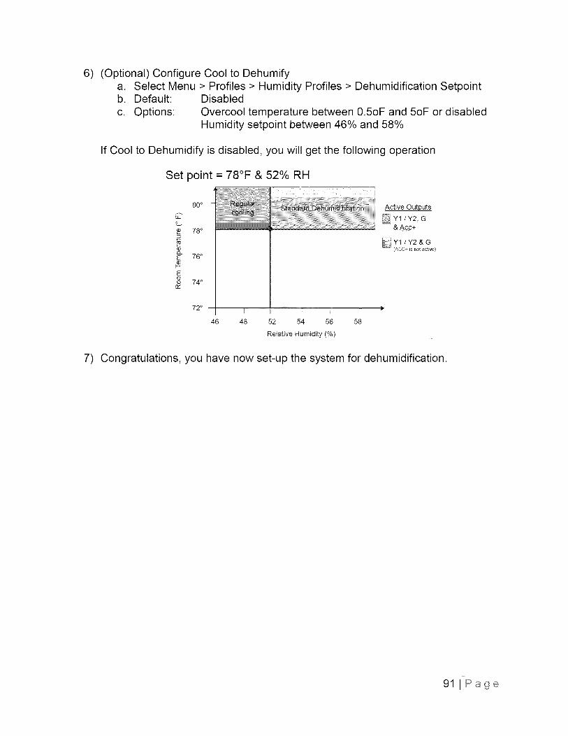
6) (Optional) Configure Cool to Dehumifya. Select Menu > Profiles > Humidity Profiles > Dehumidification Setpointb. Default: Disabled
c. Options: Overcool temperature between 0.5oF and 5oF or disabledHumidity setpoint between 46% and 58%
If Cool to Dehumidify is disabled, you will get the following operation
Set point = 78°F & 52% RH
80 o
C
78 °
E 76°
Eoo 74 °
72° I I r, I
46 48 52 54 56 58
Relative Humidity (%)
Active Outputs
Y1 / Y2, G& A_c+
7) Congratulations, you have now set-up the system for dehumidification.
91 J Page
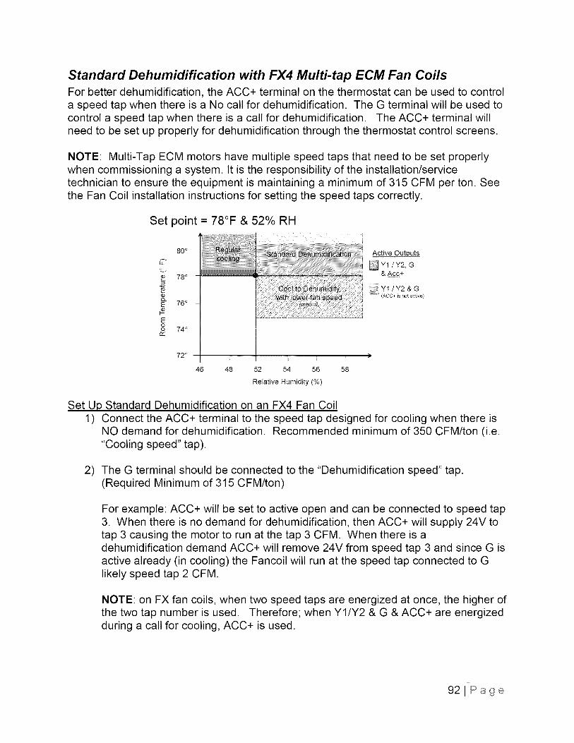
Standard Dehumidification with FX4 Multi-tap ECM Fan CoilsFor better dehumidification, the ACC+ terminal on the thermostat can be used to controla speed tap when there is a No call for dehumidification. The G terminal will be used tocontrol a speed tap when there is a call for dehumidification. The ACC+ terminal willneed to be set up properly for dehumidification through the thermostat control screens.
NOTE: Multi-Tap ECM motors have multiple speed taps that need to be set properlywhen commissioning a system. It is the responsibility of the installation/servicetechnician to ensure the equipment is maintaining a minimum of 315 CFM per ton. Seethe Fan Coil installation instructions for setting the speed taps correctly.
Set point = 78°F & 52% RH
80 o
78 o=
o_E 76°
Eoo 74 °c_
720 _ [, } [
46 48 52 54 56 58
Relative Humidity (%)
Active Outputs
Y1 tY2, G& AC.C+
Y1 / Y2 & G(ACC+ is not active)
Set Up Standard Dehumidification on an FX4 Fan Coil1) Connect the ACC+ terminal to the speed tap designed for cooling when there is
NO demand for dehumidification. Recommended minimum of 350 CFM/ton (i.e."Cooling speed" tap).
2) The G terminal should be connected to the "Dehumidification speed" tap.(Required Minimum of 315 CFM/ton)
For example: ACC+ will be set to active open and can be connected to speed tap3. When there is no demand for dehumidification, then ACC+ will supply 24V totap 3 causing the motor to run at the tap 3 CFM. When there is adehumidification demand ACC+ will remove 24V from speed tap 3 and since G isactive already (in cooling) the Fancoil will run at the speed tap connected to Glikely speed tap 2 CFM.
NOTE: on FX fan coils, when two speed taps are energized at once, the higher ofthe two tap number is used. Therefore; when Y1/Y2 & G & ACC+ are energizedduring a call for cooling, ACC+ is used.
921Page
'_ER_STAT
! Connec'_isn
D
FAN ®_L HEAT P:UMP
G
_ w:........71"....:_2
L wo E
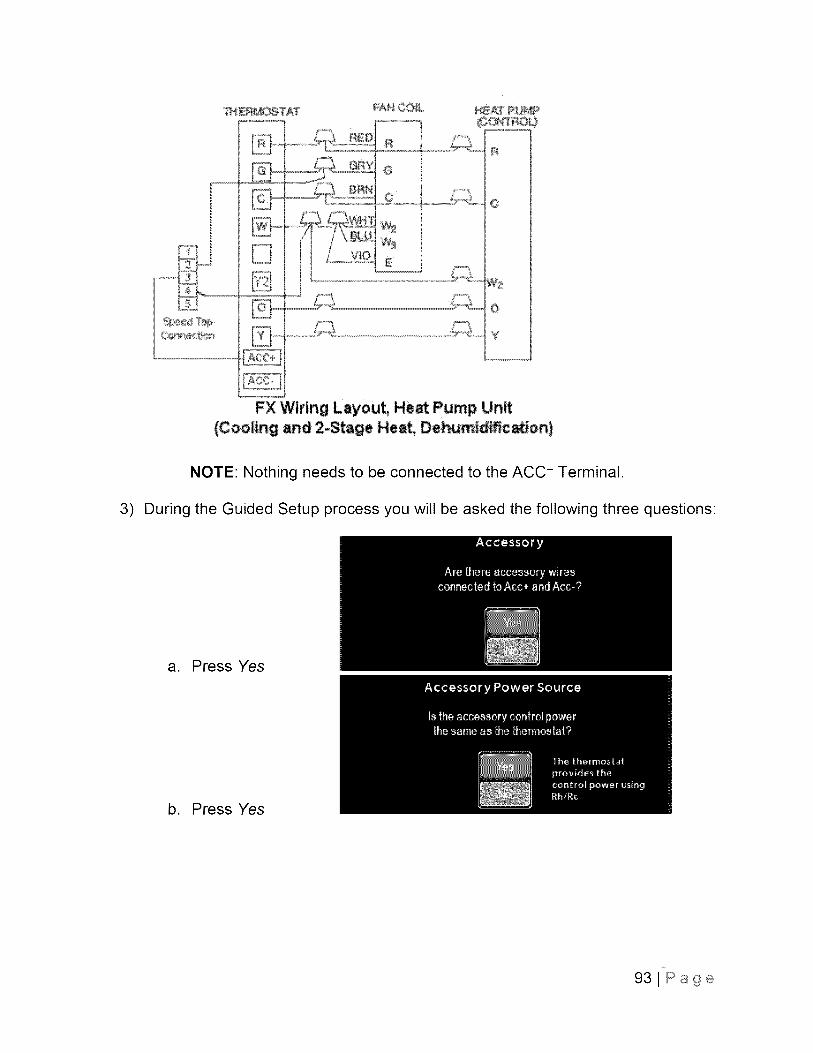
FX Wiring Layout, Heat Pump Unit
{Cooling and 2- ge Heat, Dehumid_cation)
NOTE: Nothing needs to be connected to the ACC-- Terminal.
3) During the Guided Setup process you will be asked the following three questions:
a. Press Yes
b. Press Yes
931Page
c. Press Dehumidifier
NOTE: The DHUM on fan coil board is active in the open state. The ACC+terminal for dehumidifiers is defaulted to active open. So, no other changes arenecessary. You can double check this setting on the thermostat:
Menu > (hold) Service > Installation Settings > Equipment Setup >Accessory > Dehum open
4) Complete the Guided Setup installation process
5) (Optional) Configure Cool to Dehumifya. Select Menu > Profiles > Humidity Profiles > Dehumidification Setpointb. Default: Disabled
c. Options: Overcool temperature between 0.5oF and 5oF or disabledHumidity setpoint between 46% and 58%
If Cool to Dehumidify is disabled, you will get the following operation
Set point = 78°F & 52% RH
80°
78°
Q
E 76°
Eoo 74 °
r¢
72 ° I I [, I
46 48 52 54 56 58
Relative Humidity (%)
Active Outputs
Y1 / Y2, G& A_c+
6) Congratulations, you have now set-up the system for dehumidification.
941Page
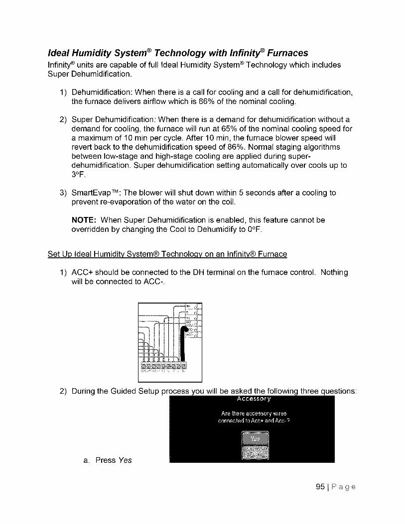
Ideal Humidity System ® Technology with Infinity _ FurnacesInfinity® units are capable of full Ideal Humidity System ® Technology which includesSuper Dehumidification.
1) Dehumidification: When there is a call for cooling and a call for dehumidification,the furnace delivers airflow which is 86% of the nominal cooling.
2) Super Dehumidification: When there is a demand for dehumidification without ademand for cooling, the furnace will run at 65% of the nominal cooling speed fora maximum of 10 min per cycle. After 10 min, the furnace blower speed willrevert back to the dehumidification speed of 86%. Normal staging algorithmsbetween low-stage and high-stage cooling are applied during super-dehumidification. Super dehumidification setting automatically over cools up to3OF.
3) SmartEvapTM: The blower will shut down within 5 seconds after a cooling toprevent re-evaporation of the water on the coil.
NOTE: When Super Dehumidification is enabled, this feature cannot beoverridden by changing the Cool to Dehumidify to 0°F.
Set Up Ideal Humidity System® Technoloqy on an Infinity® Furnace
1) ACC+ should be connected to the DH terminal on the furnace control.will be connected to ACC-.
Nothing
2) During the Guided Setup process you will be asked the following three questions:
a. Press Yes
951Page
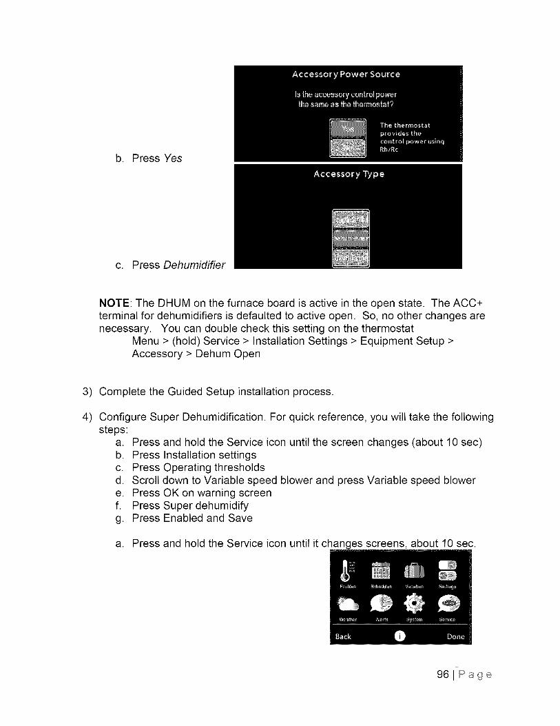
b. Press Yes
c. Press Dehumidifier
NOTE: The DHUM on the furnace board is active in the open state. The ACC+terminal for dehumidifiers is defaulted to active open. So, no other changes arenecessary. You can double check this setting on the thermostat
Menu > (hold) Service > Installation Settings > Equipment Setup >Accessory > Dehum Open
3) Complete the Guided Setup installation process.
4) Configure Super Dehumidification. For quick reference, you will take the followingsteps:
a. Pressb. Pressc. Press
d. Scrolle. Pressf. Press
g. Press
and hold the Service icon until the screen changes (about 10 sec)Installation settingsOperating thresholdsdown to Variable speed blower and press Variable speed blowerOK on warning screenSuper dehumidifyEnabled and Save
a. Press and hold the Service icon until it changes screens, about 10 sec.
i .....
96JPage
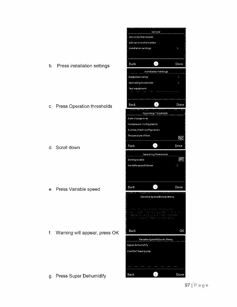
b. Press installation settings
c. Press Operation thresholds
d. Scroll down
e. Press Variable speed
f. Warning will appear, press OK
g. Press Super Dehumidify
971Page
h. Press Enabled and Save
5) Congratulations, the furnace, air conditioner or heat pump and thermostat willnow work together to bring you all the benefits of Ideal Humidity System®Technology.
Furnace Dehumidification with Performance Furnaces
Enhanced dehumidification is achieved by reducing the blower speed to 90% of thecooling blower speed during a call for dehumidification. You can also choose to useCool to Dehumidify and set the cooling off delay to 0 to prevent re-evaporating water onthe coil after a cooling cycle.
When the call for cooling is satisfied and there is a demand for dehumidification, thecooling blower-off delay is decreased from 90 seconds to 5 seconds. If unit is incontinuous fan, there will not be an off delay.
Set Up Dehumidification on Performance Furnaces
1) ACC+ should be connected to the DH terminal on the furnace control. Nothingwill be connected to ACC-.
981Page
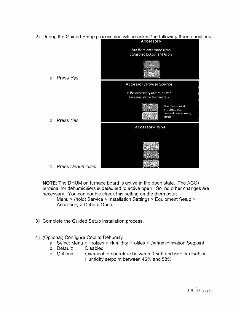
2) During the Guided Setup process 'ou will be asked the three uestions:
a. Press Yes
b. Press Yes
c. Press Dehumidifier
NOTE: The DHUM on furnace board is active in the open state. The ACC+terminal for dehumidifiers is defaulted to active open. So, no other changes arenecessary. You can double check this setting on the thermostat
Menu > (hold) Service > Installation Settings > Equipment Setup >Accessory > Dehum Open
3) Complete the Guided Setup installation process.
4) (Optional) Configure Cool to Dehumifya. Select Menu > Profiles > Humidity Profiles > Dehumidification Setpointb. Default: Disabled
c. Options: Overcool temperature between 0.5oF and 5oF or disabledHumidity setpoint between 46% and 58%
991Page
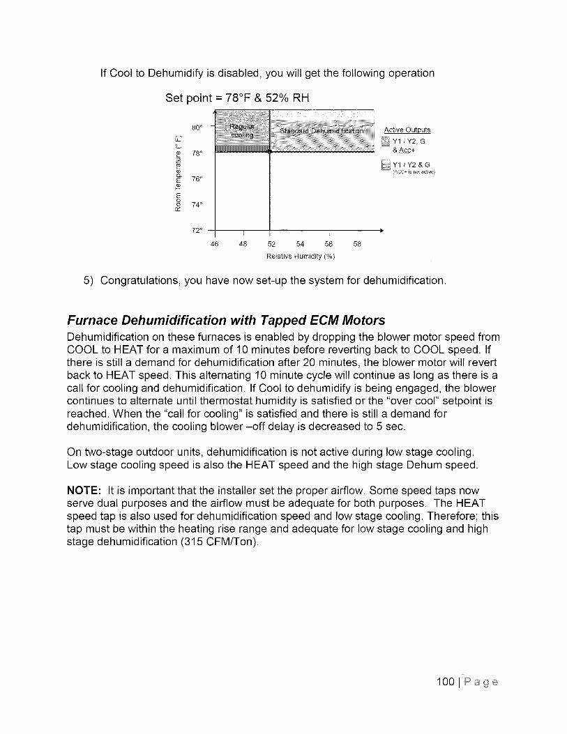
If Cool to Dehumidify is disabled, you will get the following operation
Set point = 78°F & 52% RH
80 o
78 °
Q
E 76°#Eoo 74 °
QI
72 ° I I [ I
46 48 52 54 56 58
Relative Humidity (%)
Active Outputs
YI/Y2 G& A_c+
5) Congratulations, you have now set-up the system for dehumidification.
Furnace Dehumidification with Tapped ECM MotorsDehumidification on these furnaces is enabled by dropping the blower motor speed fromCOOL to HEAT for a maximum of 10 minutes before reverting back to COOL speed. Ifthere is still a demand for dehumidification after 20 minutes, the blower motor will revertback to HEAT speed. This alternating 10 minute cycle will continue as long as there is acall for cooling and dehumidification. If Cool to dehumidify is being engaged, the blowercontinues to alternate until thermostat humidity is satisfied or the "over cool" setpoint isreached. When the "call for cooling" is satisfied and there is still a demand fordehumidification, the cooling blower -off delay is decreased to 5 sec.
On two-stage outdoor units, dehumidification is not active during low stage cooling.Low stage cooling speed is also the HEAT speed and the high stage Dehum speed.
NOTE: It is important that the installer set the proper airflow. Some speed taps nowserve dual purposes and the airflow must be adequate for both purposes. The HEATspeed tap is also used for dehumidification speed and low stage cooling. Therefore; thistap must be within the heating rise range and adequate for low stage cooling and highstage dehumidification (315 CFM/Ton).
lO01Page
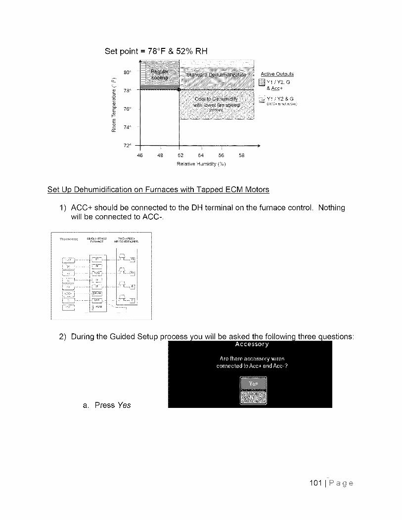
Set point = 78°F & 52% RH
80 °
C
78 o
¢or-_E 76°
Eoo 74 °c_
72 ° l b I I
46 48 52 54 56 58
Relative Humidity (%)
Active Outputs
Y1 /Y2, G& A._c_c+
iiiiizil/ Y1 / Y2 & G(ACC+ is not active)
Set Up Dehumidification on Furnaces with Tapped ECM Motors
1) ACC+ should be connected to the DH terminal on the furnace control.will be connected to ACC-.
Nothing
2) During the Guided Setup process you will be asked the following three questions:
a. Press Yes
101 I Page
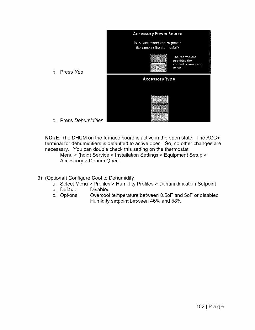
b. Press Yes
c. Press Dehumidifier
NOTE: The DHUM on the furnace board is active in the open state. The ACC+terminal for dehumidifiers is defaulted to active open. So, no other changes arenecessary. You can double check this setting on the thermostat
Menu > (hold) Service > Installation Settings > Equipment Setup >Accessory > Dehum Open
3) (Optional) Configure Cool to Dehumidifya. Select Menu > Profiles > Humidity Profiles > Dehumidification Setpointb. Default: Disabled
c. Options: Overcool temperature between 0.5oF and 5oF or disabledHumidity setpoint between 46% and 58%
1021Page
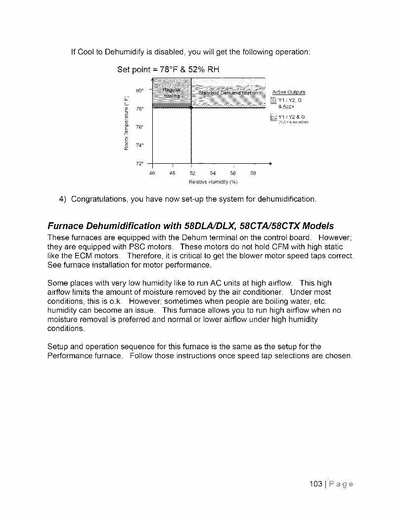
If Cool to Dehumidify is disabled, you will get the following operation:
Set point = 78°F & 52% RH
80 o
C
78 °
Q
E 76°#Eoo 74 °
QI
72 ° I I [ I
46 48 52 54 56 58
Relative Humidity (%)
Active Outputs
YI/Y2 G& A_c+
4) Congratulations, you have now set-up the system for dehumidification.
Furnace Dehumidification with 58DLA/DLX, 58CTA/58CTX Models
These furnaces are equipped with the Dehum terminal on the control board. However;they are equipped with PSC motors. These motors do not hold CFM with high staticlike the ECM motors. Therefore, it is critical to get the blower motor speed taps correct.See furnace installation for motor performance.
Some places with very low humidity like to run AC units at high airflow. This highairflow limits the amount of moisture removed by the air conditioner. Under mostconditions, this is o.k. However; sometimes when people are boiling water, etc.humidity can become an issue. This furnace allows you to run high airflow when nomoisture removal is preferred and normal or lower airflow under high humidityconditions.
Setup and operation sequence for this furnace is the same as the setup for thePerformance furnace. Follow those instructions once speed tap selections are chosen.
1031Page
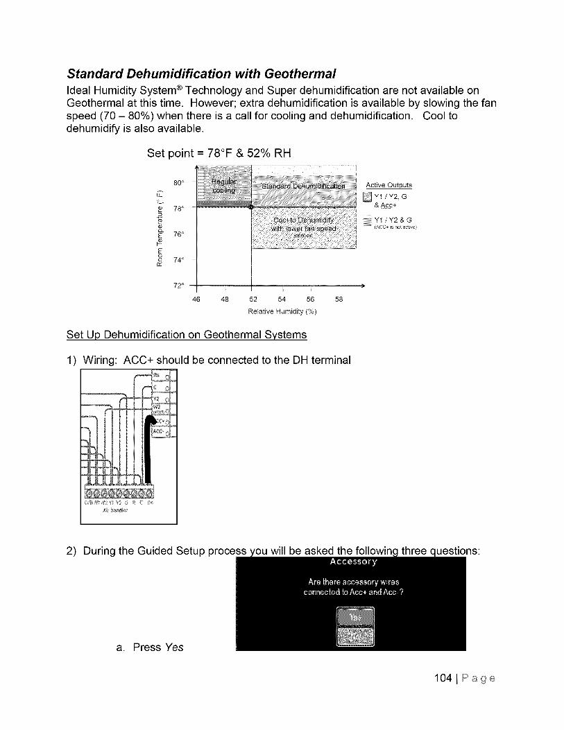
Standard Dehumidification with Geothermal
Ideal Humidity System ® Technology and Super dehumidification are not available onGeothermal at this time. However; extra dehumidification is available by slowing the fanspeed (70 - 80%) when there is a call for cooling and dehumidification. Cool todehumidify is also available.
Set point = 78°F & 52% RH
80 °
78 °
03
E 76°
Eoo 74 °r,-
72 °
46
l [, I I
48 52 54 56 58
Relative Humidity (%)
Active Outputs
Y1 !Y2, G& A_c_c+
_ii_iii/ Y1 / Y2 & Giiiiiiiiii
(ACC+ is not active)
Set Up Dehumidification on Geothermal Systems
1) Wiring: ACC+ should be connected to the DH terminal
2) During the Guided Setup process you will be asked the following three questions:
a. Press Yes
1041Page
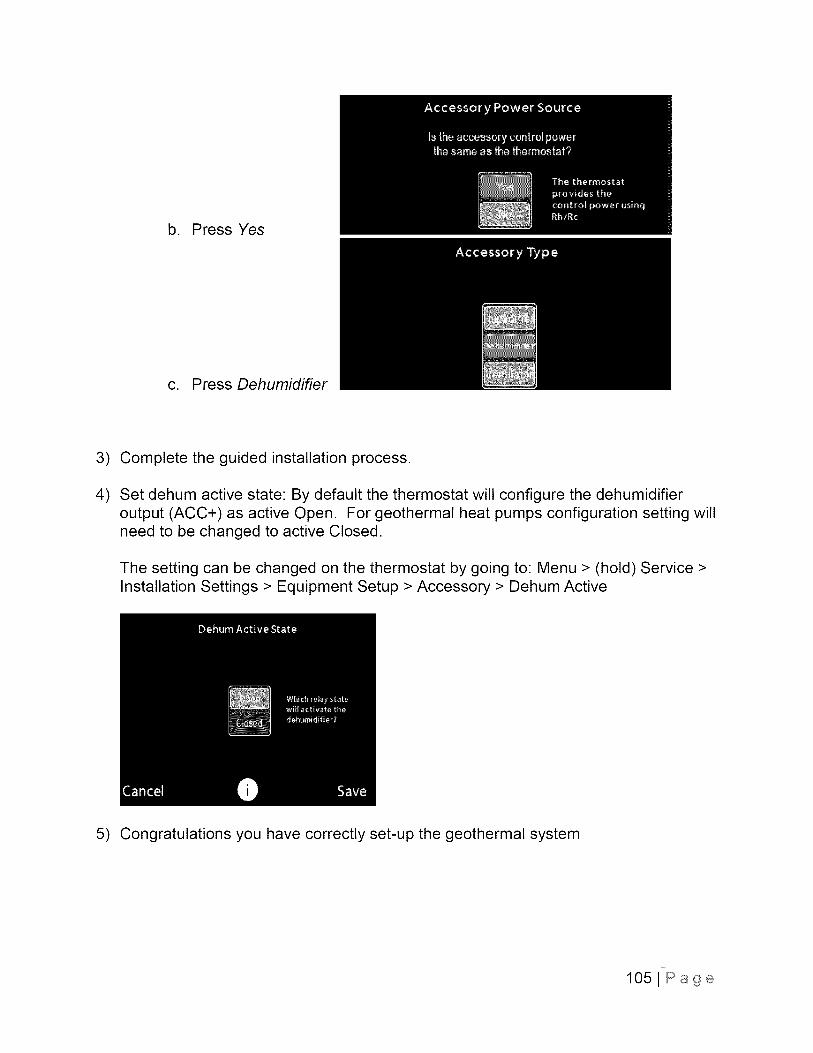
b. Press Yes
c. Press Dehumidifier
3) Complete the guided installation process.
4) Set dehum active state: By default the thermostat will configure the dehumidifieroutput (ACC+) as active Open. For geothermal heat pumps configuration setting willneed to be changed to active Closed.
The setting can be changed on the thermostat by going to: Menu > (hold) Service >Installation Settings > Equipment Setup > Accessory > Dehum Active
5) Congratulations you have correctly set-up the geothermal system
1051 Page
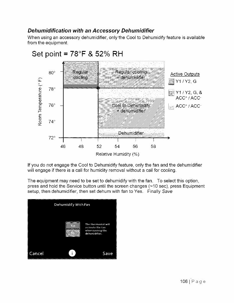
Dehumidification with an Accessory DehumidifierWhen using an accessory dehumidifier, only the Cool to Dehumidify feature is availablefrom the equipment.
Set point = 78°F & 52% RH
80 °
LL
78 °
E 76°
E0o 74 °rY
72 ° i
46 48 52 54 56
Relative Humidity (%)
58
Active Outputs
Y1 /Y2, G
&ACC ÷ / ACC-
ACC ÷ / ACC-
If you do not engage the Cool to Dehumidify feature, only the fan and the dehumidifierwill engage if there is a call for humidity removal without a call for cooling.
The equipment may need to be set to dehumidify with the fan. To select this option,press and hold the Service button until the screen changes (~10 sec), press Equipmentsetup, then dehumidifier, then set dehum with fan to Yes. Finally Save
1061Page
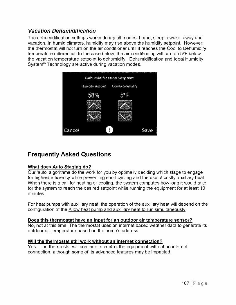
Va ca tion Dehumidifica tion
The dehumidification settings works during all modes: home, sleep, awake, away andvacation. In humid climates, humidity may rise above the humidity setpoint. However;the thermostat will not turn on the air conditioner until it reaches the Cool to Dehumidifytemperature differential. In the case below, the air conditioning will turn on 5°F belowthe vacation temperature setpoint to dehumidify. Dehumidification and Ideal HumiditySystem ® Technology are active during vacation modes.
Frequently Asked Questions
What does Auto Staqing do?Our 'auto' algorithms do the work for you by optimally deciding which stage to engagefor highest efficiency while preventing short cycling and the use of costly auxiliary heat.When there is a call for heating or cooling, the system computes how long it would takefor the system to reach the desired setpoint while running the equipment for at least 10minutes.
For heat pumps with auxiliary heat, the operation of the auxiliary heat will depend on theconfiguration of the Allow heat pump and auxiliary heat to run simultaneously.
Does this thermostat have an input for an outdoor air temperature sensor?No, not at this time. The thermostat uses an internet based weather data to generate itsoutdoor air temperature based on the home's address.
Will the thermostat still work without an internet connection?
Yes. The thermostat will continue to control the equipment without an internetconnection, although some of its advanced features may be impacted.
1071Page
What happens when weather data is not available?This thermostat uses internet based weather data to generate an outdoor airtemperature reading for your home's location. Outdoor air temperature is used as aninput for a few features (listed below).
If the internet connection to the thermostat is lost, it can continue to operate theequipment normally for up to 8 hours from its last downloaded temperature and weatherforecast.
Without weather data, the equipment will operate as follows:• Smart Setback - determines the optimal setback and ramp time between each
change in your schedule based on indoor temperature delta and historicalperformance.
Auxiliary Heat Temperature- the system will return to normal staging. Staging isdependent on the Compressor minimum on-time, Compressor stage 2temperature delta, Compressor stage one maximum run-time, auxiliary heattemperature delta and auxiliary heat minimum delay time
• Cooling Lockout - unit will try to run whenever there is a call for cooling
Can I calibrate the thermostat's temperature readinq?Temperature sensors used in modern thermostats have defined tolerance intervals ofnormal temperature readings. This means if multiple of the same thermostat modelwere installed side-by-side, it would be normal for different current temperatures to bedisplayed (e.g. one at 72°F and one at 71°F). However, there are product features andinstallation steps you can take to help ensure a comfortable environment.
Installation best practices for temperature accuracy:4. Minimize the effect of air leakage, excess wiring should be pushed into the
wall and the hole should be sealed to prevent air leakage.
5. Leave the thermostat installed & powered on for at least 30 minutes beforechecking calibration.
If the thermostat reading still needs adjusting after these two installation steps, adjustthe Room Air Temperature Thermostat Offset. The thermostat is adjustable between0°F and 5°F.
On Thermostat:
Select Menu > (hold) Service > Installation Settings > Thresholds > TemperatureOffset
1081Page
Why does the thermostat not enqage heatinq / coolinq until the indoortemperature drops 2°F below setpoint?The thermostat's Temperature Differential Settings for heating & cooling determine whatindoor temperature to engage the equipment. By default the thermostat is set to runwhen the difference between setpoint and indoor temperature is more than 0.5°F foroccupied comfort profiles (Home, Wake, Sleep). As part of the energy savingalgorithms, the thermostat relaxes this setting by an additional I°F for unoccupiedcomfort profiles (Away). Thus by default, when in the away mode the thermostat is setto run when the difference between setpoint and indoor temperature is more than 1.5°F.The occupied comfort profile Differential Settings are adjustable.
Why is the thermostat .qeneratinq an auxiliary heat alert?The thermostat can be configured to generate alerts when auxiliary heat has beenrunning for a long time or when auxiliary heat is running above a given outdoortemperature. These alerts are intended to be informative and can be adjusted ordisabled at any time on the thermostat under Menu > Alerts > Preferences.
Auxiliary heat can be engaged at high outdoor temperatures when the indoortemperature setpoint is manually increased above the Auxiliary Heat TemperatureDelta.
The Auxiliary Heat Runtime Alert will be generated if the auxiliary heat has run for morethan the Auxiliary Heat Runtime Setting within a single day. For instance, if the alert isset to 3 hours, an alert will be generated if the auxiliary heat has run for more than 3hours that day.
1091 Page