Embed Size (px)
Citation preview

Capital drilling equipmentAdvanced, field-proven risers, diverters and connectors
GEOG_VG_CDE_A4_032608 3/26/08 2:31 PM Page 1

Capital drilling equipmentVetcoGray, a GE Oil & Gas business, has been buildingits reputation as a highly skilled and experienced supplierof drilling equipment to the oil and gas industry since1906, when Regan Forge began manufacturing crownblocks and travelling blocks for the California explorationmarket. Today, we are one of the world’s leading suppliersof marine drilling riser systems. Our legacy of technologydevelopment and innovative solutions puts us in theforefront of offshoredrilling, especially for deepwaterexploration. VetcoGray supplied the complete drillingriser system for the world’s first , and to date, only,exploration well in water depths greater than 10,000 ft.We provide a complete line of capital drilling equipmentfor jackup and floating rig drilling applications.
Diverters for floating drilling unitsKFDS . . . . . . . . . . . . . . . . . . . . . . . . . . . . . . . . . . . . . . . . . . . . . . . . 4
CSO: Complete Shut-Off . . . . . . . . . . . . . . . . . . . . . . . . . . . . . . 4
Diverters for jackup and platform drilling unitsKFDJ . . . . . . . . . . . . . . . . . . . . . . . . . . . . . . . . . . . . . . . . . . . . . . . . . 5
KFDJ model “J” . . . . . . . . . . . . . . . . . . . . . . . . . . . . . . . . . . . . . . . 6
Drilling riser system componentsTelescopic joint . . . . . . . . . . . . . . . . . . . . . . . . . . . . . . . . . . . . . . 8
Tension rings
KT . . . . . . . . . . . . . . . . . . . . . . . . . . . . . . . . . . . . . . . . . . . . . . . 9
SDL/SLS . . . . . . . . . . . . . . . . . . . . . . . . . . . . . . . . . . . . . . . . 10
SDC . . . . . . . . . . . . . . . . . . . . . . . . . . . . . . . . . . . . . . . . . . . . . 12
Marine drilling riser
MR-6H SE riser . . . . . . . . . . . . . . . . . . . . . . . . . . . . . . . . . . . 14
MR-6H SE riser adapter . . . . . . . . . . . . . . . . . . . . . . . . . 15
MR-6E riser. . . . . . . . . . . . . . . . . . . . . . . . . . . . . . . . . . . . . . 16
HMF riser . . . . . . . . . . . . . . . . . . . . . . . . . . . . . . . . . . . . . . . 17
Ancillary riser equipmentMarine riser handling spiders . . . . . . . . . . . . . . . . . . . . 18
Gimbal . . . . . . . . . . . . . . . . . . . . . . . . . . . . . . . . . . . . . . . . . . 18
Single flex joint . . . . . . . . . . . . . . . . . . . . . . . . . . . . . . . . . 19
Intermediate flex joint . . . . . . . . . . . . . . . . . . . . . . . . . . 19
Subsea connectorsH-4 hydraulic subsea connectors
E H-4 . . . . . . . . . . . . . . . . . . . . . . . . . . . . . . . . . . . . . . . . . . . 20
ExF H-4 . . . . . . . . . . . . . . . . . . . . . . . . . . . . . . . . . . . . . . . . . 20
ExF HAR . . . . . . . . . . . . . . . . . . . . . . . . . . . . . . . . . . . . . . . 20
DWHD H-4 . . . . . . . . . . . . . . . . . . . . . . . . . . . . . . . . . . . . . 20
SHD H-4 . . . . . . . . . . . . . . . . . . . . . . . . . . . . . . . . . . . . . . . 21
VX-2®, VGX-2® and VT-2® gaskets . . . . . . . . . . . . . . . . . . . . 22
Aftermarket supportRiser Inspection (RADAR) . . . . . . . . . . . . . . . . . . . . . . . . . . . . 24
Corporate overview . . . . . . . . . . . . . . . . . . . . . . . . . . . . . . . . 26
32
GEOG_VG_CDE_A4_032608 3/26/08 2:31 PM Page 2

KFDJ diverter
54
The KFDJ diverter system is used on platforms and jack-up rigs to protect against shallow gas kicks during drillingoperations. In the event of a shallow gas kick, the diverteris energized to seal around the drill pipe and divert thegas safely overboard.
Features and benefits
• Complete protection while running casing strings anddrilling hole is provided by a full range of insert packersizes, all of which use a “J” type running tool
• Available with a rotating insert which provides lowpressure packoff on the kelly or drill pipe during drilling
• Fixed support housing, a proprietary feature, issecurely bolted to the rotary beams and provides fixedoutlets for flowline, fill-up line and vent lines
KFDJ diverter
All dimensions in inches. * Number and size of outlets are optional.
Diverters for floating drilling units Diverters for jackup and platform drilling units
B
C
D
G
EF
RotarySupportStructure Locking
Dogs
Flowline VentOutlets
FlowlineSeals
OvershotSpool
EC-6Coupling
SupportHousing
Fill UpLine
RetainerBolts
InsertPacker
DiverterAssembly
ARotary Table
• Support housing allows installation of outlets up to 20”diameter to virtually any configuration
• Diverter, spacer spool and overshot packer assembly maybe pulled or run without connecting or disconnecting theflowline, fill-up line and vent lines
• Mudline suspension hangers and bit sizes up to 27.41”for 37-1/2” rotaries or 36.41” for 49-1/2” rotaries canbe run without removing the diverter assembly
• Diverter, spacer spool and overshot packer each fitthrough a 37-1/2” rotary table. Minimum bore throughthe standard support housing is 36-1/2” ID for the 37-1/2”in rotary installation. Optional 37-1/2” bore is available
• Overshot packer on the bottom of the diverter spacerspool assembly reduces the nipple-up time normallyrequired to weld flanges or hubs to casing
All dimensions in inches. * Number and size of outlets are optional.
Flex JointCrossover Flange
Standard Housing HasMultiple Outlets, Up To20” Diameter
DiverterSupport Housing
Pressure EnergizedFlow Line Seals
Spherical Element
Diverter Assembly
24.25”
Running Tool Profile
EDB
CA
The CSO (Complete Shut-off) Diverter is used on floatingdrilling rigs to divert shallow gas overboard prior toinstallation of the BOP. Once the BOP has been installedthe diverter is used to vent gas in the riser, above theBOP. The CSO model can seal on either drill pipe or anopen hole.
Features and benefits
• Housing accommodates large diameter riser buoyancymodules
• Complete open-hole shut-off with 20" through-bore
• 15 - 10 second closure time on pipe or open hole
• 500 psi rated system
• Control system maximum operating pressure of 1,500 psi
• High capacity systems available for supporting the riserstring from the diverter housing in emergency hangoffsituations
• Connection block enables hydraulic operating functionsto be quickly attached or disconnected
• Standard housing holds multiple outlets, up to 20"diameter
CSO diverter
KFDS diverterVetcoGray is one of the market leaders for diverter sys-tems in the offshore drilling market. We are a single-sourcesupplier for complete systems including diverter assembly,controls and valves. An integrated package, engineeredto specific requirements, provides maximum safety, efficiencyand savings. For 25 years, VetcoGray has provided KFDSdiverter technology with field-proven protection from shallowgas blowouts.
Features and benefits
• Diverter support housing, overboard lines and associated valving are permanently installed on the rig structure
• Diverter assembly is run and retrieved through the rotary table with the marine riser
• Variable outlet sizes and orientations can accommodatevirtually any rig design
• Valving is external, allowing for rig design variation and valve/actuator preferences
Outlet nom. (in.) A B C D E
12 11.38 16.38 15.38 43.75 71.50
14 12.50 17.00 16.00 45.00 72.75
16 14.31 18.00 17.00 47.00 74.75
18 16.50 19.00 18.00 49.00 76.75
20 18.38 20.00 19.00 51.00 78.75
Dimensional data: CSO diverter
Rotary table A B C D E F G
37.50 42.50 37.25 37.25 37.25 37.25 37.25 37.25
49.50 53.00 49.25 49.25 49.25 49.25 49.25 49.25
Dimensional data: CSO diverter standard hookup KFDJ
GEOG_VG_CDE_A4_032608 3/26/08 2:31 PM Page 4

6
Diverters for jackup and platform drilling units Diverters for jackup and platform drilling units
Designed with all the field proven features of the standardKFDJ diverter, but with fewer hydraulic connections,VetcoGray’s KFDJ model “J” diverter system has a “J” lockbetween the diverter and the support housing.
KFDJ model “J” diverter
All dimensions in inches. * Number and size of outlets are optional.
KFDJ model “J” diverter
D
B
A
F
E
C
Locking Mechanism
RotaryBeams
(Diverter)
(Housing)
RotaryTable
Features and benefits
• Simplified design
• Only three hydraulic functions: energizing/venting the diverter packing, the flowline seals, and the overshot packer
• "J" slots in the support housing align the diverter outlets with the housing outlets
• A mechanical latch secures the diverter in the housingand provides a visual indicator of lock engagement
• All components of the support housing and the diverterassembly area feature heavy wall construction forpressure containment and erosion protection duringhigh velocity, multi-phase flow
• Insert packers are available in a full range of sizes
• Custom designed for specific applications
Diverter Insert
Diverter Support Housing
Newly installed KFDJ diverter
Rotary table A B C D E F
37.50 78.50 36.50 27.50 36.25 35.25 15.62
49.50 73.25 47.00 27.50 46.75 35.25 10.40
49.50 96.50 47.00 36.50 46.75 35.25 29.40
Dimensional data: standard hookup KDFJ “J” with 12” nominal outlets*
GEOG_VG_CDE_A4_032608 3/26/08 2:31 PM Page 6
98 9
Telescopic joint
Telescopic joint
Drilling riser system components Drilling riser system components
The telescopic joint compensates for heave and offset ofthe vessel and is available for all riser systems. This move-ment is achieved through the stroking movement of theinner and outer barrel of the telescopic joint .
Features and benefits
• Available for MR-6E, MR-6H SE, and HMF risersystems
• Maximum rated riser tensile load capacityin locked position
• Hydraulic latch release for inner and outerbarrels available
• Dual split/solid packer elements
• Fixed or rotating integral tension rings
• Prepped for non-integral SDL, SDC andKT tension rings
• Fluid or roller bearing prep
Tension rings
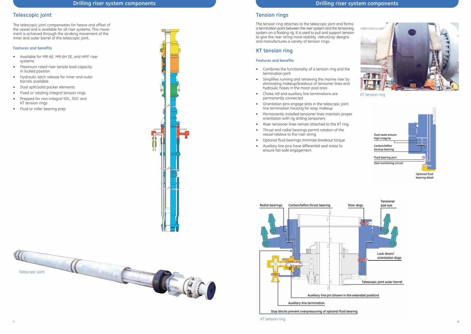
KT tension ring
The tension ring attaches to the telescopic joint and formsa termination point between the riser system and the tensioningsystem on a floating rig. It is used to pull and support tensionto give the riser string more stability. VetcoGray designsand manufactures a variety of tension rings.
Features and benefits
• Combines the functionality of a tension ring and thetermination joint
• Simplifies running and retrieving the marine riser byeliminating makeup/breakout of tensioner lines andhydraulic hoses in the moon pool area
• Choke, kill and auxiliary line terminations are permanently connected
• Orientation pins engage slots in the telescopic jointline termination housing for easy makeup
• Permanently installed tensioner lines maintain properorientation with rig drilling tensioners
• Riser tensioner lines remain attached to the KT ring
• Thrust and radial bearings permit rotation of the vessel relative to the riser string
• Optional fluid bearings minimize breakout torque
• Auxiliary line pins have differential seal areas toensure fail-safe engagement
KT tension ring
KT tension ring
GEOG_VG_CDE_A4_032608 3/26/08 2:31 PM Page 8

Drilling riser system components Drilling riser system components
Features and benefits
Similarities between SDL and SLS rings
• Riser tensioner lines remain attached to the SDL/SLSring so riser tensioner lines are properly spaced at all times
• Both rings use pad eyes for connection with the tensioner lines
• When not in use, the rings lock and store to a matingprofile on the bottom of the diverter support housingfor convenient and orderly storage
• Telescopic joint is run and pulled through the rotarytable without disconnecting the tensioner lines fromthe SDL/SLS ring
• Hydraulic piping for lockdown/storage dogs remainspermanently connected
Differences between SDL and SLS rings
• SDL ring utilizes a gear-driven dog load interface withthe telescopic joint
• SDL rings do not have a fluid bearing; it is integral withthe telescopic joint for this configuration
• SLS rings utilize a load-shoulder interface with the telescopic joint
• SLS rings have an integral fluid bearing
SDL/SLS tension ring
SDL tension support ring with optional fluid or roller bearing
SDL Tension Support Ring
VetcoGray’s tension rings are proven to perform in theharsh environments of deepwater drilling Convenient and
orderly storage
GEOG_VG_CDE_A4_032608 3/26/08 2:31 PM Page 10

1312
Drilling riser system components Drilling riser system components
SDC tension ring with KT style termination ring
SDC tension ringFeatures and benefits
• SDC rings utilize a ball-joint connection with direct-line cylinder tensioners
• Direct-line cylinders are permanently attached to theSDC ring for fast and safe attachment to the telescopic joint
• A hinged split-ring design opens and closes aroundthe telescopic joint
• Designed to be opened and moved out of the wayfor storage while the tensioning cylinders remainattached
• Optional KT-style termination ring can be utilizedwith the SDC tension ring
SDC tension ring
Quick, efficient make-up
SDC tension ring - open SDC tension ring - closed
GEOG_VG_CDE_A4_032608 3/26/08 2:31 PM Page 12

1514
Marine drilling riserThis new riser adapter was created using the same tech-nology as the MR-6H SE riser coupling; however, it is self-contained and designed to be run without a spider. Theadapter was created to improve safety during the operationof making-up the connection between the top of theLMRP and the first joint of riser. Current flange designsrequire personnel to be suspended over the stack andmoon pool while making-up the connection. This is apotentially hazardous, time consuming process. In contrast,the new MR-6H SE riser adapter can be quickly connectedand released from a safe distance.
Features and benefits
Safety• Eliminates the potential hazards of riser adapter
make-up and break out
• Eliminates the need to lower heavy tools, bolts andequipment to personnel
• Reduces need for multiple rig personnel to make thisconnection
• Existing rig designs have limited clearance to make upthe riser adapter. With the MR-6H SE riser adapter, thisclearance restriction is no longer an issue
Efficiency• Significantly reduces the time to make/break
the connection.
• Utilizes field proven technology (H-4connector and dog style riser)
MR-6H SE riser adapterThe marine drilling riser connects the floating rig to thesubsea wellhead. The subsea well is drilled through theriser allowing the drilling mud to circulate back up to therig. VetcoGray offers three main types of marine drillingriser.
MR-6H SE riser
This fully-automated make-up, 3.5 million pound rated(API class 'H') is the latest offering from VetcoGray. Thedesign is simple, with very few parts, utilizing field provenconcepts and profiles which have provided many years ofexemplary service. The highly preloaded coupling withefficient load path also provides the option for incorpora-tion of a metal seal if required for higher-pressure condi-tions. The modularized, hydraulically operated handlingspider provides all mechanisms required for make-up andbreak-out of the coupling which minimizes intervention ofrig floor personnel. The spider design allows quick changeout of key subassemblies during riser running operations.
Features and benefits
• Automated make-up with minimal personnel inter-vention
• Utilizes reliable, field proven concepts and profiles (H-4 & MR)
• High preload / efficient load path
• Easy to replace parts subject to wear
• Easy maintenance, service and inspection with allcritical areas readily accessible
• External surfaces of pin and box can be fully “TSA protected”
• Handling spider modularized to allow quick changeout of critical parts or subassemblies
View of MR-6H SE riser adapter
MR-6H SE exploded view
MR-6H SE assembled
MR-6H SE profile
Drilling riser system components Drilling riser system components
GEOG_VG_CDE_A4_032608 3/26/08 2:31 PM Page 14

1716
MR-6E riserOne of the most reliable and advanced marine riser systemsin today’s market is VetcoGray’s HMF™ system. Developedthrough extensive design analysis and test programs ofbending, tension, internal pressure and functional evalua-tions, this coupling is ideal for deep water applicationswhere high load operating conditions exist . The HMF risercoupling has been field proven through many years ofworldwide use, including drilling the current water depthwell record of 10,011 feet in the Gulf of Mexico.
Features and benefits
• Meets API 16R, class D, E, F, G, H and J
• Stepped diameter design of pin and box simplifiesengagement, even with severe vessel movement
• Ideal for deep water applications where high loadoperating conditions exist
• No loose parts, all bolts and inserts stay in thepin/box flanges preventing bolt loss and potentialthread damage
• Field removable and replaceable nose ring
• Locking bolts preloaded above the rated couplingloads, which extends the fatigue life of the riser coupling
• Hydraulic running/test tool facilitates quicker riserrunning times
• Field replaceable choke and kill line stab subs
HMF riserThe MR-6E is a dog style riser connection. To make theconnection, the dogs in the box are driven into the profilein the pin, making a fully preloaded connection.
The design provides an improved and increased resistanceto high tensile loads and large bending moments, condi-tions common with today’s deepwater drilling operations.The MR-6E is lightweight, simple to operate and fast to run.
Features and benefits
• 2 million lb. rating per API 16R Class E
• Low make-up torque, 950 ft - lbs
• Simple, light weight design
• MR-6E couplings can be used interchangeably with MR-6D couplings
View of Class F, HMF riser flange pin
View of Class F, HMF riser flange pin
Class F, HMF flange riser
(1) Does not include buoyancy material (2) I.D. based on 0.625" wall thickness of principal tube (3) Includes weight of auxiliary line stab subs
Drilling riser system components Drilling riser system components
O.D. (1) I.D. (2) Length Weight (3) No. of activating screws Torque
41.125” 19.75” 23.125” 2,510 lbs 6 950 ft.-lbs.
MR-6E riser coupling specifi cations 5” C & K, 4-1/2” Boost, & 2-7/8” Hydraulic stab subs
GEOG_VG_CDE_A4_032608 3/26/08 2:31 PM Page 16

1918
Marine riser handling spider
MR-6H SE spiderThe intermediate flex joint is installed below the telescopic joint and allows for angular deflection up to 20 degrees in the top portion of the riser string.
Features and benefits
• Installed below the telescopic joint
• Up to 2.5 million lb tensile load capacity
• Angular deflection to 20 degrees on either side of itsaxial center while subjected to tensile loading andinternal pressure of 1,500 psi
Intermediate flex joint
The single flex joint is installed in the Lower Marine Riser Package (LMRP). It allows angular deflection up to10 degrees in the lower portion of the riser string. Thecombination of an elastomeric bearing and a seal unitgive it flexibility and the capacity for internal pressurecontainment of up to 3,000 psi.
Features and benefits
• Installed in the LMRP below the riser/BOP stack interface
• Uses a combination elastomeric bearing and seal unitto eliminate the need for a pressure balanced ball andsocket interface with seals
• Up to 2 million lb tensile load capacity
• Rated for H2S service and oil-based drilling mud
• Angular deflection to 10 degrees on either side of itsaxial center while subjected to tensile loading andinternal pressures up to 3,000 psi
• Pressure balance and lubrication systems not required
Single flex joint
MR-6E hydraulic spider
MR-6H SE coupling with spider
Intermediate flex joint leaving VetcoGray's facility
Single flex joint
The MR-6H SE riser handling spider supports the riser stringon hydraulic sliding dogs. Six hydraulic units move the camring up and down to make or break the connector.
HMF spider
HMF spider
The HMF hydraulic-gate riser handling spider is used whenrunning or retrieving HMF riser joints through the rotary table.Split gates, operated by hydraulic cylinders, support the riserstring when the gates are in the closed and locked position.
The spider is used to support the riser string while the connections are being made or broken while the riser string isbeing run or retrieved. VetcoGray makes a variety of styles, each compatible with specific types of riser connections.
This spider is used to support the MR-6E riser system. Thehydraulic support dogs extend to support the lower flangeof the coupling while the connection is either made or broken.
Ancillary riser equipment Ancillary riser equipment
MR-6E hydraulic spider
GimbalThe gimbal sits under the spider and acts as a shockabsorber to assist with the weight of the riser string. Itcan also compensate for up to 6 degrees of offset whilerunning or retrieving the riser string.
GEOG_VG_CDE_A4_032608 3/26/08 2:31 PM Page 18

The H-4 family of subsea connectors, introduced in 1964, arein use in every major producing region of the world and inevery type of offshore environment. The VetcoGray familyof H-4 connectors are field proven, hydraulically operated,metal-to-metal sealing connectors that are widely used for:
• BOP stack to wellhead
• LMRP to BOP stack
• Completion tree to wellhead
• TLP/subsea template tieback
• Production riser assembly to subsea manifold
• Single point mooring to anchor base
• Caisson completions and artificial island drilling
• Specially adapted applications
Ideal for deepwater use, the H-4 line of connectors has reliable,simple operating characteristics; excellent bending and tensileload capabilities; and a long, economical service life.
Features and benefits
Field proven reliability • In service since 1964
High strength connection• 355 degrees circumferential dog ring contact to the
four locking grooves of the wellhead/mandrel profile distributes bending and tensile loads uniformly
Primary and secondary hydraulic circuits• The dual hydraulic operating system generates 25%
more releasing force than locking force
Passive mechanical release • Dog profile design (45 degrees) assures passive
retraction of locking dog segments with overpull
Visual position indicator rod • Indicator rod provides positive, visual indication of
locked and unlocked position as well as cam ring travel
• Rig serviceable hydraulic systems
VX/VT back-up seal profile • All current H-4 connector designs have the VX/VT
seal profile, and have Inconel inlay for corrosion and damage protection
Easy primary seal replacement • Primary VX/VT seal is ROV replaceable and retrievable
Hydrate protection • Hydrate seals between the connector and the high
pressure wellhead housing are standard
Flush ports • In the event that hydrates form in the H-4 connector,
hydrate flushing ports located in the upper body will facilitate their removal
Seal ring protection• Connector to wellhead/mandrel interface is self-
aligning, which assures that the gasket will not be damaged during makeup
Safety• Replacement of seal ring does not require personnel
to be under connector/BOP
Pressure-tight self-energizing seal• Positive compression loading of the seal ring into the
corrosion and damage resistant seal surface profile provides reliable sealing integrity
• Optional upper body configurations available
• Individual hydraulic pistons provide multiple circuits
2120
H-4® hydraulic subsea connector familyThe SHD H-4 connector (Super Heavy Duty) is the latestmember of the H-4 family. This connector, designed foruse with the MS 700 and SMS 700 wellheads, has exceptionalbending load capacities and fatigue life characteristics. Itis ideal for deepwater, critical service where high bendingloads are anticipated.
SHD H-4 hydraulic subsea connector
Bore
Pre
ssur
e (k
si)
Bending moment (MM ft-lbs)
25
20
15
10
5
0
0 1.0 2.0 3.0 4.0 5.0 6.0 7.0 8.0
18-3/4” SHD H-4 load capacity envelopeLoad capacity at 2/3 yieldNote: Tension values at the wellhead for 3,000 psi connector locking pressure.
capacity envelope
tension - 1,500 kips
tension - 0 kips
E H-4 connector E x F H-4 connector E x F HAR H-4 connector DW HD H-4 connector
Subsea connectors Subsea connectors
SHD H-4 connector
Maximum service pressure 15,000 psi
Number of hydraulic cylinders total 10
Number of hydraulic cylinders primary 5
Number of hydraulic cylinders secondary 5
Cylinder lock area 626.35 sq in
Cylinder unlock area 785.4 sq in
Lock fl uid volume total 12.10 US Gal
Unlock fl uid volume total 12.10 US Gal
Maximum hydraulic operational pressure 15.10 US Gal
Maximum hydraulic testing pressure 3,000 psi
SHD H-4 connector specifi cations 5,000 psi
Connector wellhead preload 1,500 psi Lock 3.75 x 10⁶ lb
3,000 psi Lock 7.50 x 10⁶ lb
Maximum OD 66 in
Weight based on studded top 28,600 lbs
Swallow 32.25 in
SHD H-4 connector specifi cations
GEOG_VG_CDE_A4_032608 3/26/08 2:32 PM Page 20

MS-700 wellhead and H-4 connector in test fixture
2322
VX-2®, VGX-2® and VT-2® gaskets
VX-2, VGX-2 and VT-2 gaskets are designed to seal internal pressure in H-4 connectors
VX-2, VGX-2 and VT-2 gaskets
VX-2 gasket
MS-700 wellhead with VX-2 gasket prior to makeup withH-4 connector
The stainless steel VX-2 gasket is the standard gasket fordrilling and production; it is rated for 15,000 psi internalpressure, 250 degrees F, and is manufactured from corrosionresistant material.
The carbon steel VX-2 gasket is a lower cost/lowerperformance version. It is rated for 10,000 psi internalpressure, 250 degrees F, and is coated for corrosionresistance.
The VGX-2 gasket is a higher performance/higher costversion. It is rated for 15,000 psi internal pressure, 350degrees F, and is manufactured from high yield strengthstainless steel with a silver coating. The higher yield
strength material provides a large range of elastic action,while the silver coating provides resistance to galling. Thecoefficient of thermal expansion of the gasket approximatesthat of the wellhead and the H-4 upper body.
The VT-2 gasket seals on a secondary independent sealsurface and is used when the primary VX sealing surfaceis damaged. It is rated for 15,000 psi internal pressure,250 degrees F, and is manufactured from corrosionresistant material.
Other API sizes and optional configurations are available.Insert options include Hycar, lead, and tin indium materials.
2 seal bands 2 seal bands Radius 0.25”
Subsea connectors Subsea connectors
VX-2 gasket(gas/liquid)
VX-2 gasket(gas/liquid)
VT-2 gasket(gas/liquid)
VGX-2 gasket(gas/liquid)
Working pressure (psi)
15,000 10,000 15,000 15,000
Temperature range (ºF)
35 - 250 35 - 250 35 - 250 35 - 350
External pressure rating (psi)
1,000 2,500 1,000 3,500
Seal material Stainless steel
(316) Mild steel
Stainless steel (316)
Stainless steel /Corrosion
resistant alloy
Surface coating Moly based Moly based Moly based Moly based
PSL-4 qualifi cations yes yes yes yes
Dimensional data: VX-2, VGX-2 and VT-2 gaskets
GEOG_VG_CDE_A4_032608 3/26/08 2:32 PM Page 22

2524
Pipe thickness inspection
• Four pulse-echo longitudinal wave transducers in a 4-channel setup spaced at 90 degrees apart forincreased data acquisition speeds
Video record
• Video record of internal condition of riser body tube
Analysis programs complement the data acquisition systemand operate on the same computer platform. The processeddata are displayed in two presentations.
Color thickness map• Ultrasonic data is displayed in various colors as a
function of the depth and position along the lengthand circumference of the riser
B-Scan display• Enables the operator to use critical Rf waveform data
and the B-Scan images created from these waveformsto accurately identify and assess flaws
Reporting criteria can be customized to each particularapplication, following industry standards, or alternativecriteria based on fit-for-purpose analysis.
An internal inspection with RADAR has the primary advantagethat it eliminates all special handling, stripping or externalpreparation of the pipe. The inspection itself is performedin a third of the time required for conventional methods.
The RADAR unit and associated equipment is portable soinspections can be performed almost anywhere, includingpipe yards, remote/dockside facilities, customers' facilities,and offshore rigs, resulting in significant savings in bothtime and money.
RADAR tool for drilling riser inspectionInspections can be performed almost anywhere, even on a drillship in transit
Aftermarket support Aftermarket support
RADAR was developed to address the need for an efficient,safe and cost-effective method of internal inspection of drillingand production risers, choke and kill lines, and other metalpipes.
Features and benefits
• Uses real-time data acquisition and analysis to enable drilling contractors to monitor life-cycle wear measurements of drilling riser components
• Helps minimize risk by identifying marginal equipment
• Plan for regular repairs, maintenance and part replacement to avoid costly rig shutdowns
Inspection data for specific risers can be stored digitally foreasy retrieval and used to track riser assets by serial numberto facilitate their transfer between rigs and regions.
RADAR tools and procedures have been witnessed andcertified by DNV.
RADAR is a tool for data acquisition and analysis that performsextensive data processing to:
• Identify defects based on specific rejection criteria
• Determine location, orientation, type and size ofreportable flaws
• Present the data in a meaningful display
• Video record the internal portion of the pipe
• Identify defects based on specific rejection criteria
Weld quality inspection
• Two time-of-flight-diffraction (TOFD) channels for inspec-tion of the entire weld volume along the length of theweld
• Four pulse-echo shear wave transducers in a 4-channelsetup to analyze the root and cap regions of the weld
RADAR - Riser Active DataAcquisition Recorder
Convenient riserinspection on your rig
GEOG_VG_CDE_A4_032608 3/26/08 2:32 PM Page 24

Breadth and depthGE’s VetcoGray business has been developing industry-leading solutions for more than a century. Our specialtysystems enable superior performance around the globe – in harsh environments on land, offshore and subsea.
As the oil and gas industry matures, we provide the know-ledge and technologies to take drilling, completion andproduction further and deeper than they have ever gone.
Onshore
Surface wells are drilled and completed in every kind ofenvironment from desert sand to Arctic snow. We provideexpertise and equipment for them all. Our experience coversproduction of oil, gas and combinations with other productssuch as water, CO2 or H2S. Our products and services span the entire range of applications, whether for simple low pressure oil wells or the extreme high pressure hightemperature (HPHT) wells now being developed worldwide.
Offshore
Offshore facilities are becoming more diversified as a resultof vast differences in water depths and field characteristics.We offer an extensive portfolio of proven systems and productsincluding fixed platforms, jackups and MODUs, TLP/Spars andFPSOs. We frequently partner with our customers in off-shore field development and exploitation – providing afull range of industry-leading technologies from drillingto compression and power generation modules.
Subsea
With offshore development moving into deeper waters andmarginal fields, more advanced technologies are neededto increase reliability, flexibility, speed and performance.Our subsea wellheads and connectors have provided solidfoundations for more than 40 years. We are also at theforefront of subsea field development, with advanced systemintegration capabilities and over 1,000 systems installedworldwide. Our portfolio also includes the industry's latestand most advanced trees, production controls, manifoldsand connections, processing and distribution systems.
Strength and stabilityAs part of GE’s Oil & Gas business, VetcoGray benefits fromthe broad strategic and financial stability that enables strong,long-term investment in and development of new technologies,tools, services and human resources.
Investment
VetcoGray is committed to investing significant time andresources in order to deliver greater advantages to our customers. We invest in new technologies – researching,developing and testing extensively to ensure that only the best solutions go to market. We also invest in regionaleconomies by spreading our research, manufacturing andservice facilities around the world.
Knowledge
VetcoGray has over 100 years of experience serving the Oil & Gas industry with our field proven technology. Our customers are in a unique position to benefit, not only fromour advancements in this industry, but also from the productsand services proven by other high-tech parts of our organization.Technologies can be modified and injected from GE’sAviation, Energy, Healthcare and other businesses to improveproduct performance in oil and gas applications. We also work very closely with key customer engineeringteams to create solutions customized to their operations.
Training
In addition to extensive and demanding training requirementsfor our own personnel, we provide a variety of standard andspecialized programs for our customers. Our courses coverany of our product lines or they may be project specific.Training methods and course documentation is tailored toeach customer’s particular needs and equipment. We canaccommodate programs at any of our global facilities or atcustomer sites.
Service
We provide inspection, maintenance, repair, spare partsand upgrade services for our current and legacy equipmentin every region of the world. VetcoGray has 61 locations in32 countries. Our well established global service locationscontinue to support our customers’ needs worldwide. Ourcrews perform extensive onsite support, plus ongoingdesign and engineering solutions that help prolong equipmentlife, reduce costs, and improve performance.
Commitment
VetcoGray is fully committed to helping our customersachieve greater levels of performance and productivitythrough all phases of Oil & Gas drilling and production.
On land and at sea
One source,many solutions
Corporate Overview Corporate Overview
GEOG_VG_CDE_A4_032608 3/26/08 2:32 PM Page 26

VG_CDE_A4_032608
GE Oil & Gas
HeadquartersNuovo Pignone S.p.A.Via Felice Matteucci 250127 Florence ItalyT +39 055 423 211F +39 055 423 [email protected]
VetcoGray Inc.Headquarters3010 Briarpark Avenue, Suite 300Houston, Texas 77042P.O. Box 2291Houston, Texas 77252-2291T +1 713 683 2400F +1 713 683 2421
For complete contact information,please refer to our website.
www.geoilandgas.com/vetcogray
The information contained herein is general in nature and is not intended for specific construction, installation or application purposes. GE reserves the right to makechanges in specifications or add improvements at any time without notice or obligation.
©2008 General Electric CompanyAll Rights Reserved
GE imagination at work
GEOG_VG_CDE_A4_032608 3/26/08 2:32 PM Page 28