Embed Size (px)
Citation preview
Copyright 2004 ASHRAE, 1791 Tullie Circle NE, Atlanta, GA 30329. All rights reserved. This is a draft document intended only for internal use by the Society, including review and discussion. It may not be copied or redistributed in paper or digital form or posted on an unsecured Web site without written permission from ASHRAE. ASHRAE has compiled this draft document with care, but ASHRAE has not investigated, and ASHRAE expressly disclaims any duty to investigate, and product, service, process, procedure, design, or the like that may be described herein. The appearance of any technical data or editorial material in this draft document does not constitute endorsement, warranty, or guaranty by ASHRAE of any product, service, process, procedure, design, or the like, and ASHRAE expressly disclaims same. ASHRAE does not warrant that the information in this draft document is free of errors, and ASHRAE does not necessarily agree with any statement or opinion in this draft document.
Advanced Energy Design Guide: Small Office
Buildings
100% Final Draft
(Rev 5) May 10, 2004
This is a 100% final draft (R5) document for review only and not for general distribution. May 10, 2004
2
SP-102 Membership Ron Jarnagin, SP-102 Chair Bruce Hunn, Staff Liaison Don Colliver, Cognizant Committee Ex Officio Joe Deringer, AIA Representative Jim Edelson, NBI Representative Jay Enck, ASHRAE TC 2.8 Representative Michael Lane, IESNA Representative Merle McBride, ASHRAE At-large Representative Hayden McKay, IESNA Representative Harry Misuriello, ASHRAE TC 7.6 Representative Daniel Nall, AIA Representative Don Steiner, ASHRAE SSPC 90.1 Representative Donna Leban, AIA Representative
Cognizant Committee Membership Don Colliver, Cognizant Chair Ed Jackson, AIA Representative Rita Harrold, IESNA Representative Jeff Johnson, NBI Representative Terry Townsend, ASHRAE ExCom Representative Mark Case, ASHRAE TC 2.8 Representative Ron Majette, DOE Representative Adam Hinge, ASHRAE TC 7.6 Representative Jerry White, ASHRAE SSPC 90.1 Representative Ron Jarnagin, SP-102 Chair – Ex Officio Bruce Hunn, Staff Liaison
This is a 100% final draft (R5) document for review only and not for general distribution. May 10, 2004
3
Advanced Energy Design Guide: Small Office Buildings
Section 1 - Introduction Section 3 – Integrated Process to Achieve Energy Savings
Section 3 - Recommendations by Climate Zone Section 4 - “How-To” Implement Recommendations Appendix – Envelope Thermal Performance Factors
This is a 100% final draft (R5) document for review only and not for general distribution. May 10, 2004
4
Section 1 - Introduction The Advanced Energy Design Guide: Small Office Buildings (Guide) is intended to provide a simple and easy approach for use by contractors and designers who design and construct office buildings up to 20,000 ft2. Application of the recommendations in the Guide should result in small office buildings with 30% energy savings when compared to those same office buildings designed to the minimum requirements of ANSI/ASHRAE/IESNA Standard 90.1-1999. This document contains recommendations, and is not a minimum code or standard. It is intended to be used in addition to the existing codes and standards and is not intended to circumvent them. This Guide represents a way, but not the only way, for owners, designers and contractors to build energy efficient small offices buildings which use significantly less energy than those built to the minimum code requirements. The recommendations in this Guide provide benefits and savings for the building owner while maintaining quality and functionality of the office space. This Guide has been developed by a committee representing a diverse group of energy professionals drawn from the American Society of Heating, Refrigerating, and Air Conditioning Engineers (ASHRAE), the American Institute of Architects (AIA), the New Buildings Institute (NBI), and the Illuminating Engineering Society of North America (IESNA). To quantify the expected energy savings these professionals selected potential envelope, lighting, HVAC, and service water heating energy saving measures for analysis. These included products that were deemed to be both practical and commercially available. Although some of the products may be considered premium, products of similar performance are available from multiple manufacturers. Each set of measures was simulated using an hour-by-hour building energy analysis computer program for two small office prototypes in representative cities in various climates. Simulations were run for reference buildings (buildings designed to Standard 90.1-1999 criteria) compared to buildings built using recommendations contained in this Guide to determine that the expected 30% savings target was achieved. The Scope of this Guide covers small office buildings up to 20,000 ft2 in size which use unitary heating and air conditioning equipment. Buildings of this size with these HVAC system configurations represent a large fraction of commercial office space in the United States, and thus the Guide focuses on them. Because the design and construction of many of these smaller buildings may not involve the use of traditional design professionals due to budget considerations, this Guide provides straightforward recommendations and “how-to” guidance to facilitate its use by anyone in the construction process in producing more energy efficient buildings. Section 2 of this Guide contains a chart that walks the user through the design process of applying the recommendations in this Guide, while Section 3 provides the actual recommendations for a way to meet the 30% energy savings goal. Section 4 provides the essential guidance to help the user to understand and apply the recommendations from this Guide. In addition, this Guide provides recommendations that would assist the user in achieving energy efficiency credits for LEED™ or other building energy rating systems. This Guide includes specific recommendations for energy efficient improvements in the following technical areas to meet the 30% goal:
• Building Envelope o Roofs o Walls
This is a 100% final draft (R5) document for review only and not for general distribution. May 10, 2004
5
o Floors o Slabs o Doors o Vertical Glazing o Skylights
• Lighting o Daylighting o Interior Electric Lighting o Controls
• HVAC Equipment and Systems o Cooling Equipment Efficiencies o Heating Equipment Efficiencies o Supply Fans o Ventilation Control o Ducts
• Service Water Heating o Equipment efficiencies o Pipe insulation
In addition, strategies to improve energy efficiency beyond the 30% are included for:
• Exterior Façade Lighting • Parking Lot Lighting • Plug Loads
This is a 100% final draft (R5) document for review only and not for general distribution. May 10, 2004
6
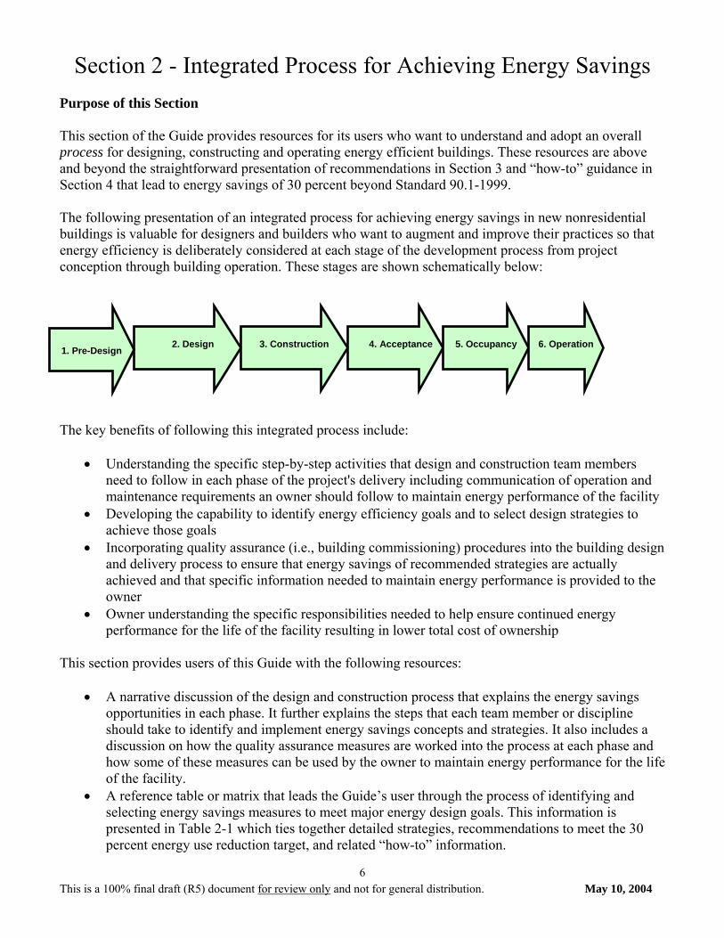
Section 2 - Integrated Process for Achieving Energy Savings Purpose of this Section This section of the Guide provides resources for its users who want to understand and adopt an overall process for designing, constructing and operating energy efficient buildings. These resources are above and beyond the straightforward presentation of recommendations in Section 3 and “how-to” guidance in Section 4 that lead to energy savings of 30 percent beyond Standard 90.1-1999. The following presentation of an integrated process for achieving energy savings in new nonresidential buildings is valuable for designers and builders who want to augment and improve their practices so that energy efficiency is deliberately considered at each stage of the development process from project conception through building operation. These stages are shown schematically below: The key benefits of following this integrated process include:
• Understanding the specific step-by-step activities that design and construction team members need to follow in each phase of the project's delivery including communication of operation and maintenance requirements an owner should follow to maintain energy performance of the facility
• Developing the capability to identify energy efficiency goals and to select design strategies to achieve those goals
• Incorporating quality assurance (i.e., building commissioning) procedures into the building design and delivery process to ensure that energy savings of recommended strategies are actually achieved and that specific information needed to maintain energy performance is provided to the owner
• Owner understanding the specific responsibilities needed to help ensure continued energy performance for the life of the facility resulting in lower total cost of ownership
This section provides users of this Guide with the following resources:
• A narrative discussion of the design and construction process that explains the energy savings opportunities in each phase. It further explains the steps that each team member or discipline should take to identify and implement energy savings concepts and strategies. It also includes a discussion on how the quality assurance measures are worked into the process at each phase and how some of these measures can be used by the owner to maintain energy performance for the life of the facility.
• A reference table or matrix that leads the Guide’s user through the process of identifying and selecting energy savings measures to meet major energy design goals. This information is presented in Table 2-1 which ties together detailed strategies, recommendations to meet the 30 percent energy use reduction target, and related “how-to” information.
2. Design 1. Pre-Design
3. Construction 4. Acceptance 5. Occupancy 6. Operation
This is a 100% final draft (R5) document for review only and not for general distribution. May 10, 2004
7
Duluth - Energy
0.00 10.00 20.00 30.00 40.00 50.00 60.00 70.00 80.00 90.00 100.00
ASHRAE/ IESNA 90.1Base Case
(a) Efficient Systems
kbtu/sf/yr
LightingCoolingHeatingFansPlug LoadDHWAux.
Miami - Energy
0.00 10.00 20.00 30.00 40.00 50.00 60.00 70.00 80.00 90.00 100.00
ASHRAE/ IESNA 90.1Base Case
(a) Efficient Systems
kbtu/sf/yr
LightingCoolingHeatingFansPlug LoadDHWAux.
Users of this Guide are encouraged to study this recommended process and determine if their design and construction practice could benefit from its use.
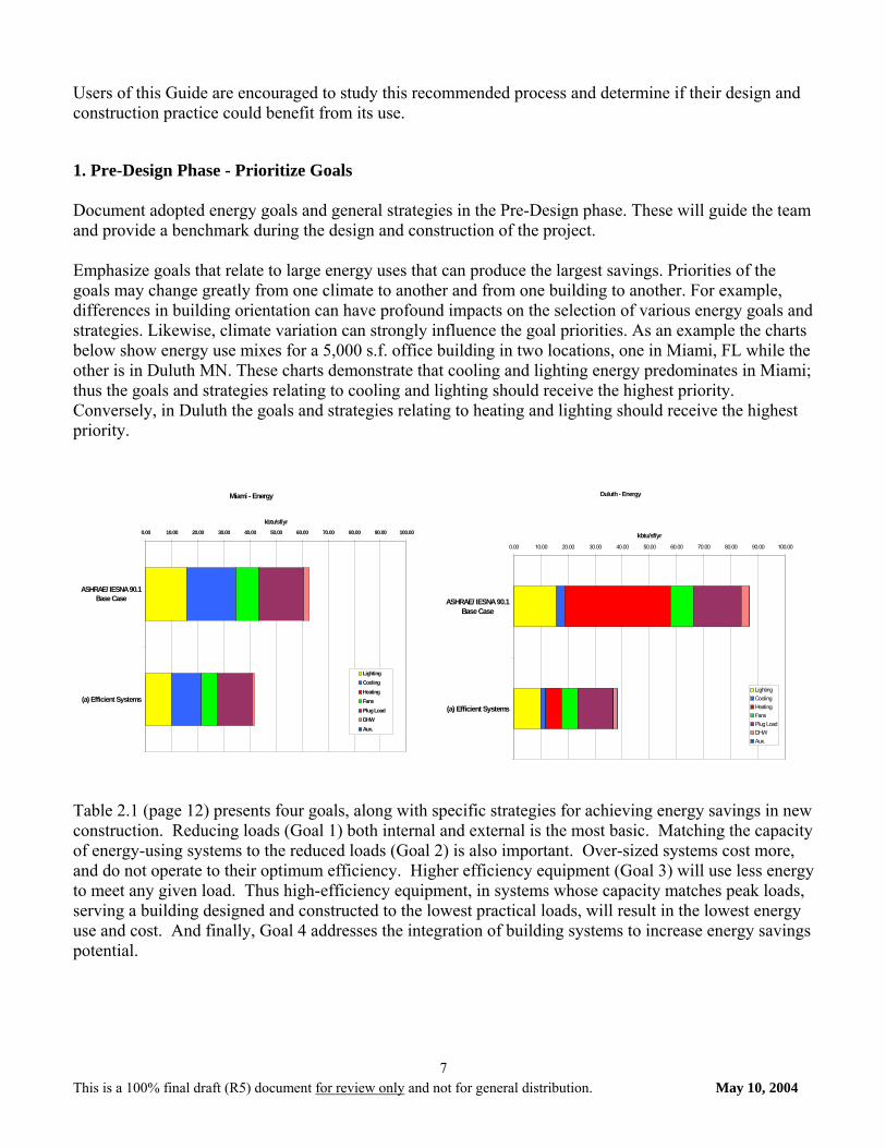
1. Pre-Design Phase - Prioritize Goals Document adopted energy goals and general strategies in the Pre-Design phase. These will guide the team and provide a benchmark during the design and construction of the project. Emphasize goals that relate to large energy uses that can produce the largest savings. Priorities of the goals may change greatly from one climate to another and from one building to another. For example, differences in building orientation can have profound impacts on the selection of various energy goals and strategies. Likewise, climate variation can strongly influence the goal priorities. As an example the charts below show energy use mixes for a 5,000 s.f. office building in two locations, one in Miami, FL while the other is in Duluth MN. These charts demonstrate that cooling and lighting energy predominates in Miami; thus the goals and strategies relating to cooling and lighting should receive the highest priority. Conversely, in Duluth the goals and strategies relating to heating and lighting should receive the highest priority. Table 2.1 (page 12) presents four goals, along with specific strategies for achieving energy savings in new construction. Reducing loads (Goal 1) both internal and external is the most basic. Matching the capacity of energy-using systems to the reduced loads (Goal 2) is also important. Over-sized systems cost more, and do not operate to their optimum efficiency. Higher efficiency equipment (Goal 3) will use less energy to meet any given load. Thus high-efficiency equipment, in systems whose capacity matches peak loads, serving a building designed and constructed to the lowest practical loads, will result in the lowest energy use and cost. And finally, Goal 4 addresses the integration of building systems to increase energy savings potential.
This is a 100% final draft (R5) document for review only and not for general distribution. May 10, 2004
8
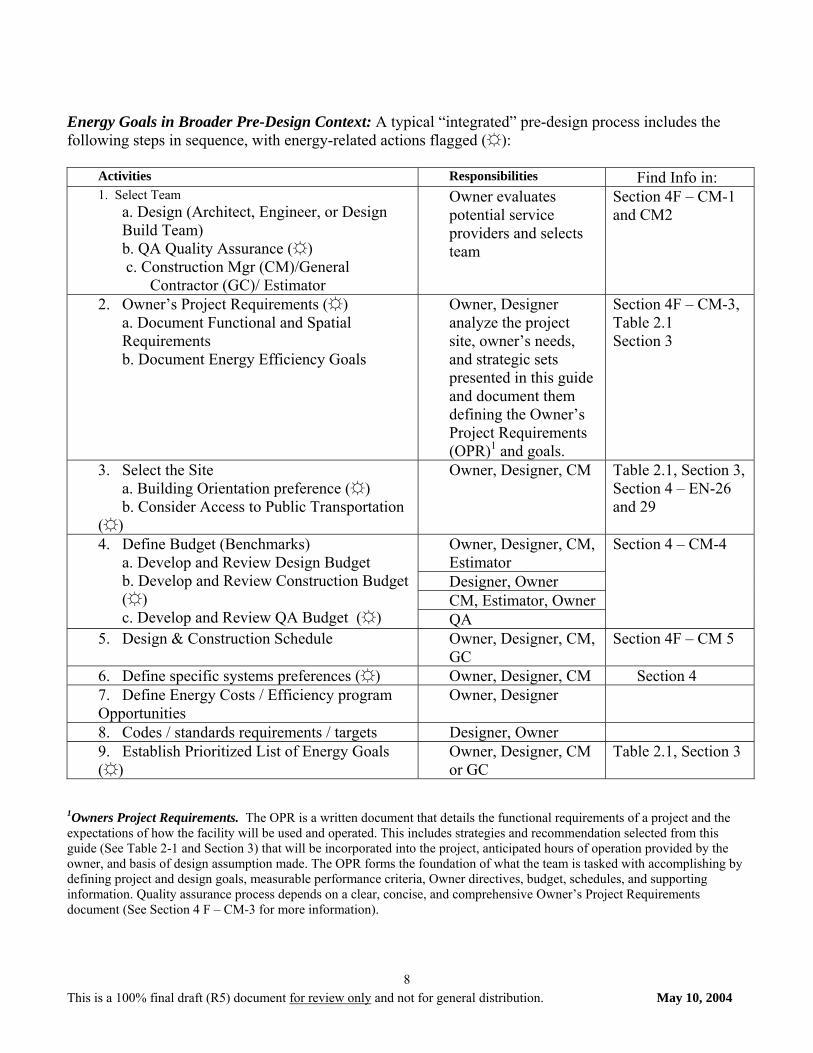
Energy Goals in Broader Pre-Design Context: A typical “integrated” pre-design process includes the following steps in sequence, with energy-related actions flagged (☼):
Activities Responsibilities Find Info in: 1. Select Team
a. Design (Architect, Engineer, or Design Build Team) b. QA Quality Assurance (☼) c. Construction Mgr (CM)/General
Contractor (GC)/ Estimator
Owner evaluates potential service providers and selects team
Section 4F – CM-1 and CM2
2. Owner’s Project Requirements (☼) a. Document Functional and Spatial Requirements b. Document Energy Efficiency Goals
Owner, Designer analyze the project site, owner’s needs, and strategic sets presented in this guide and document them defining the Owner’s Project Requirements (OPR)1 and goals.
Section 4F – CM-3, Table 2.1 Section 3
3. Select the Site a. Building Orientation preference (☼)
b. Consider Access to Public Transportation (☼)
Owner, Designer, CM Table 2.1, Section 3, Section 4 – EN-26 and 29
Owner, Designer, CM, Estimator Designer, Owner CM, Estimator, Owner
4. Define Budget (Benchmarks) a. Develop and Review Design Budget b. Develop and Review Construction Budget (☼) c. Develop and Review QA Budget (☼) QA
Section 4 – CM-4
5. Design & Construction Schedule Owner, Designer, CM, GC
Section 4F – CM 5
6. Define specific systems preferences (☼) Owner, Designer, CM Section 4 7. Define Energy Costs / Efficiency program Opportunities
Owner, Designer
8. Codes / standards requirements / targets Designer, Owner 9. Establish Prioritized List of Energy Goals (☼)
Owner, Designer, CM or GC
Table 2.1, Section 3
1Owners Project Requirements. The OPR is a written document that details the functional requirements of a project and the expectations of how the facility will be used and operated. This includes strategies and recommendation selected from this guide (See Table 2-1 and Section 3) that will be incorporated into the project, anticipated hours of operation provided by the owner, and basis of design assumption made. The OPR forms the foundation of what the team is tasked with accomplishing by defining project and design goals, measurable performance criteria, Owner directives, budget, schedules, and supporting information. Quality assurance process depends on a clear, concise, and comprehensive Owner’s Project Requirements document (See Section 4 F – CM-3 for more information).
This is a 100% final draft (R5) document for review only and not for general distribution. May 10, 2004
9
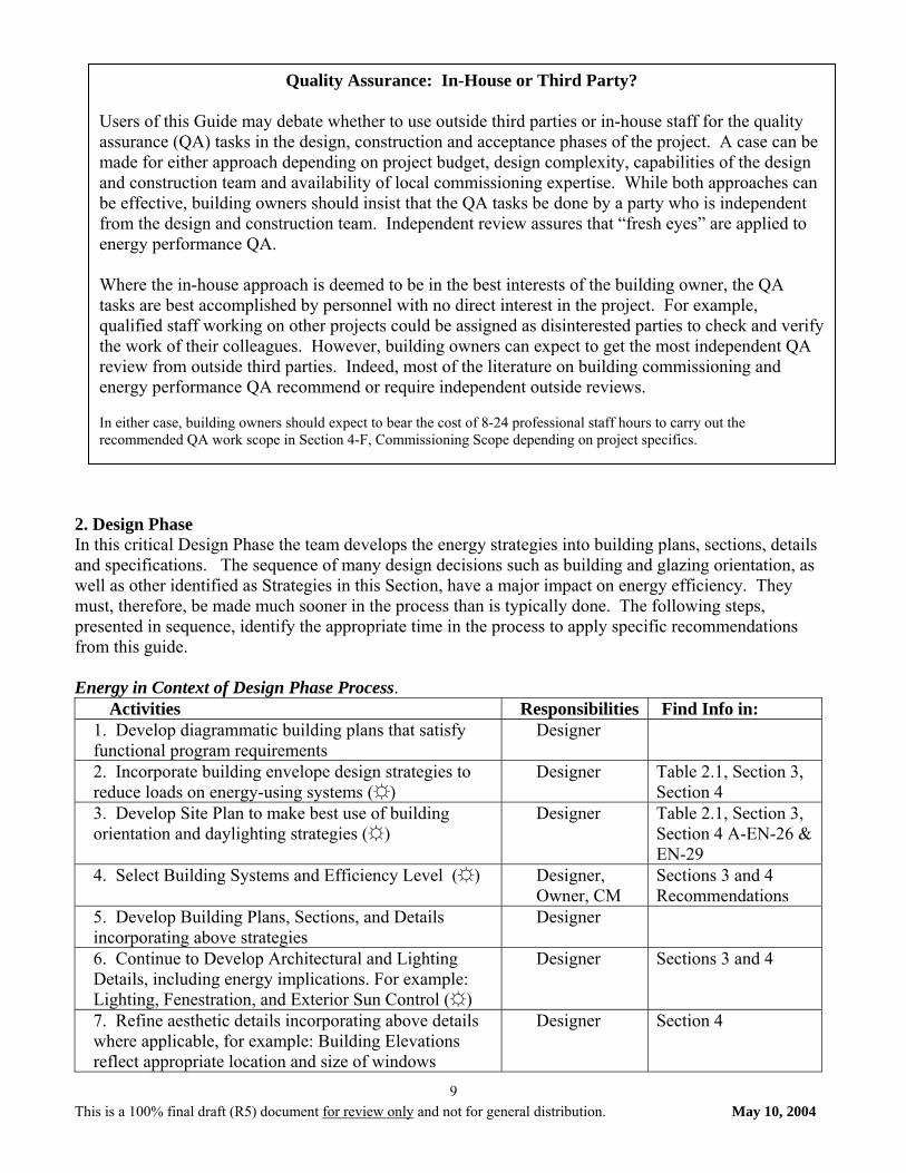
2. Design Phase In this critical Design Phase the team develops the energy strategies into building plans, sections, details and specifications. The sequence of many design decisions such as building and glazing orientation, as well as other identified as Strategies in this Section, have a major impact on energy efficiency. They must, therefore, be made much sooner in the process than is typically done. The following steps, presented in sequence, identify the appropriate time in the process to apply specific recommendations from this guide. Energy in Context of Design Phase Process.
Activities Responsibilities Find Info in: 1. Develop diagrammatic building plans that satisfy functional program requirements
Designer
2. Incorporate building envelope design strategies to reduce loads on energy-using systems (☼)
Designer Table 2.1, Section 3, Section 4
3. Develop Site Plan to make best use of building orientation and daylighting strategies (☼)
Designer Table 2.1, Section 3, Section 4 A-EN-26 & EN-29
4. Select Building Systems and Efficiency Level (☼) Designer, Owner, CM
Sections 3 and 4 Recommendations
5. Develop Building Plans, Sections, and Details incorporating above strategies
Designer
6. Continue to Develop Architectural and Lighting Details, including energy implications. For example: Lighting, Fenestration, and Exterior Sun Control (☼)
Designer Sections 3 and 4
7. Refine aesthetic details incorporating above details where applicable, for example: Building Elevations reflect appropriate location and size of windows
Designer Section 4
Quality Assurance: In-House or Third Party? Users of this Guide may debate whether to use outside third parties or in-house staff for the quality assurance (QA) tasks in the design, construction and acceptance phases of the project. A case can be made for either approach depending on project budget, design complexity, capabilities of the design and construction team and availability of local commissioning expertise. While both approaches can be effective, building owners should insist that the QA tasks be done by a party who is independent from the design and construction team. Independent review assures that “fresh eyes” are applied to energy performance QA. Where the in-house approach is deemed to be in the best interests of the building owner, the QA tasks are best accomplished by personnel with no direct interest in the project. For example, qualified staff working on other projects could be assigned as disinterested parties to check and verify the work of their colleagues. However, building owners can expect to get the most independent QA review from outside third parties. Indeed, most of the literature on building commissioning and energy performance QA recommend or require independent outside reviews. In either case, building owners should expect to bear the cost of 8-24 professional staff hours to carry out the recommended QA work scope in Section 4-F, Commissioning Scope depending on project specifics.
This is a 100% final draft (R5) document for review only and not for general distribution. May 10, 2004
10
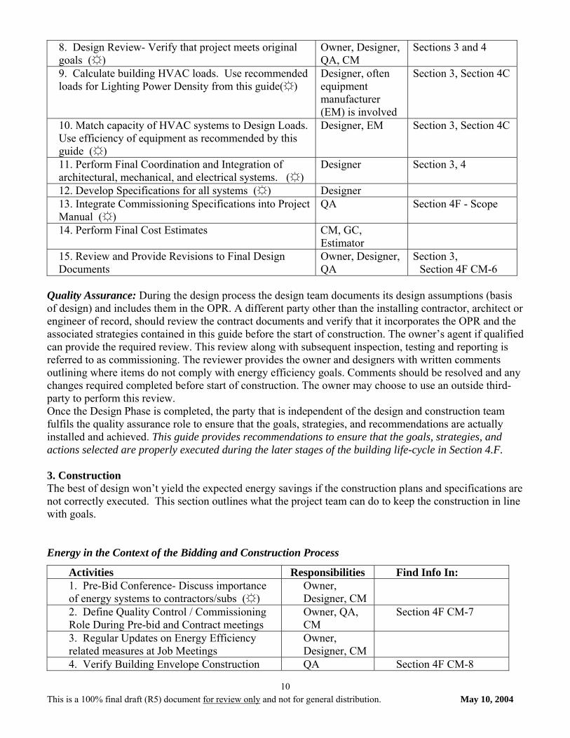
8. Design Review- Verify that project meets original goals (☼)
Owner, Designer, QA, CM
Sections 3 and 4
9. Calculate building HVAC loads. Use recommended loads for Lighting Power Density from this guide(☼)
Designer, often equipment manufacturer (EM) is involved
Section 3, Section 4C
10. Match capacity of HVAC systems to Design Loads. Use efficiency of equipment as recommended by this guide (☼)
Designer, EM Section 3, Section 4C
11. Perform Final Coordination and Integration of architectural, mechanical, and electrical systems. (☼)
Designer Section 3, 4
12. Develop Specifications for all systems (☼) Designer 13. Integrate Commissioning Specifications into Project Manual (☼)
QA Section 4F - Scope
14. Perform Final Cost Estimates CM, GC, Estimator
15. Review and Provide Revisions to Final Design Documents
Owner, Designer, QA
Section 3, Section 4F CM-6
Quality Assurance: During the design process the design team documents its design assumptions (basis of design) and includes them in the OPR. A different party other than the installing contractor, architect or engineer of record, should review the contract documents and verify that it incorporates the OPR and the associated strategies contained in this guide before the start of construction. The owner’s agent if qualified can provide the required review. This review along with subsequent inspection, testing and reporting is referred to as commissioning. The reviewer provides the owner and designers with written comments outlining where items do not comply with energy efficiency goals. Comments should be resolved and any changes required completed before start of construction. The owner may choose to use an outside third-party to perform this review. Once the Design Phase is completed, the party that is independent of the design and construction team fulfils the quality assurance role to ensure that the goals, strategies, and recommendations are actually installed and achieved. This guide provides recommendations to ensure that the goals, strategies, and actions selected are properly executed during the later stages of the building life-cycle in Section 4.F. 3. Construction The best of design won’t yield the expected energy savings if the construction plans and specifications are not correctly executed. This section outlines what the project team can do to keep the construction in line with goals. Energy in the Context of the Bidding and Construction Process
Activities Responsibilities Find Info In: 1. Pre-Bid Conference- Discuss importance of energy systems to contractors/subs (☼)
Owner, Designer, CM
2. Define Quality Control / Commissioning Role During Pre-bid and Contract meetings
Owner, QA, CM
Section 4F CM-7
3. Regular Updates on Energy Efficiency related measures at Job Meetings
Owner, Designer, CM
4. Verify Building Envelope Construction QA Section 4F CM-8
This is a 100% final draft (R5) document for review only and not for general distribution. May 10, 2004
11
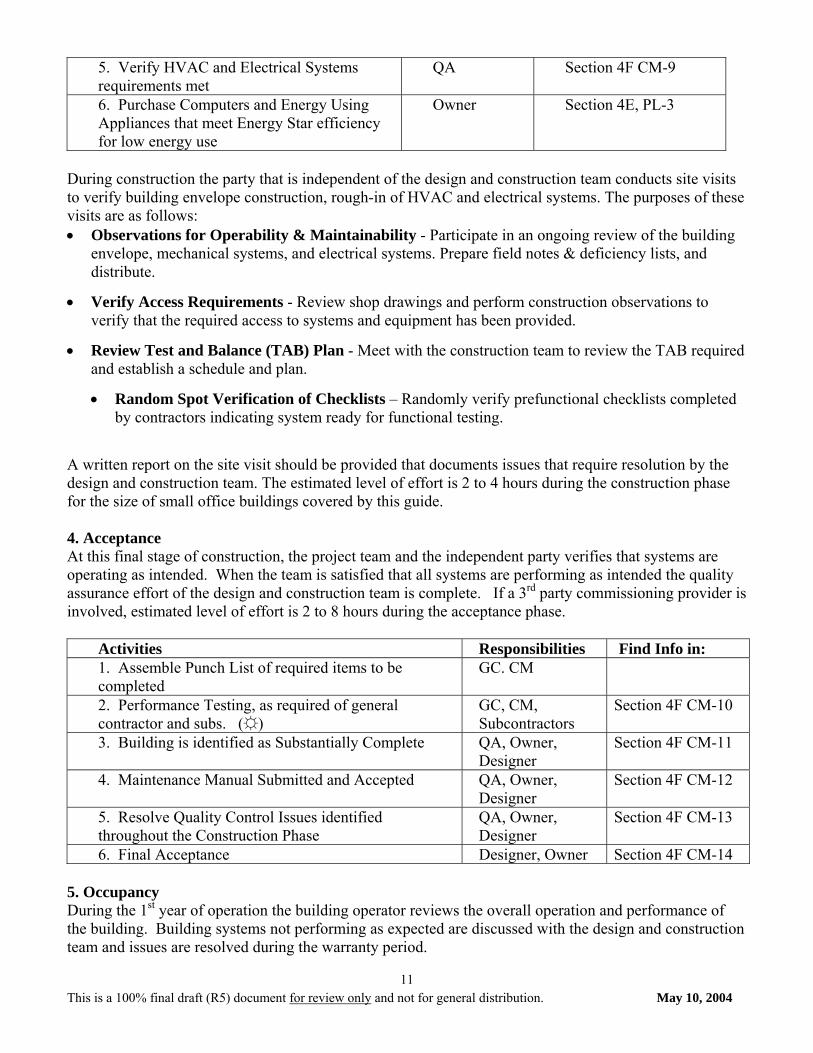
5. Verify HVAC and Electrical Systems requirements met
QA Section 4F CM-9
6. Purchase Computers and Energy Using Appliances that meet Energy Star efficiency for low energy use
Owner Section 4E, PL-3
During construction the party that is independent of the design and construction team conducts site visits to verify building envelope construction, rough-in of HVAC and electrical systems. The purposes of these visits are as follows: • Observations for Operability & Maintainability - Participate in an ongoing review of the building
envelope, mechanical systems, and electrical systems. Prepare field notes & deficiency lists, and distribute.
• Verify Access Requirements - Review shop drawings and perform construction observations to verify that the required access to systems and equipment has been provided.
• Review Test and Balance (TAB) Plan - Meet with the construction team to review the TAB required and establish a schedule and plan.
• Random Spot Verification of Checklists – Randomly verify prefunctional checklists completed by contractors indicating system ready for functional testing.
A written report on the site visit should be provided that documents issues that require resolution by the design and construction team. The estimated level of effort is 2 to 4 hours during the construction phase for the size of small office buildings covered by this guide. 4. Acceptance At this final stage of construction, the project team and the independent party verifies that systems are operating as intended. When the team is satisfied that all systems are performing as intended the quality assurance effort of the design and construction team is complete. If a 3rd party commissioning provider is involved, estimated level of effort is 2 to 8 hours during the acceptance phase.
Activities Responsibilities Find Info in: 1. Assemble Punch List of required items to be completed
GC. CM
2. Performance Testing, as required of general contractor and subs. (☼)
GC, CM, Subcontractors
Section 4F CM-10
3. Building is identified as Substantially Complete QA, Owner, Designer
Section 4F CM-11
4. Maintenance Manual Submitted and Accepted QA, Owner, Designer
Section 4F CM-12
5. Resolve Quality Control Issues identified throughout the Construction Phase
QA, Owner, Designer
Section 4F CM-13
6. Final Acceptance Designer, Owner Section 4F CM-14 5. Occupancy During the 1st year of operation the building operator reviews the overall operation and performance of the building. Building systems not performing as expected are discussed with the design and construction team and issues are resolved during the warranty period.
This is a 100% final draft (R5) document for review only and not for general distribution. May 10, 2004
12
Activities Responsibilities Find Info in: Establish Building Maintenance Program Owner and staff,
QA Section 4F CM-15
Create Post- Occupancy Punch List Owner and staff Monitor Post-Occupancy Performance Owner and staff
QA Section 4F CM-16
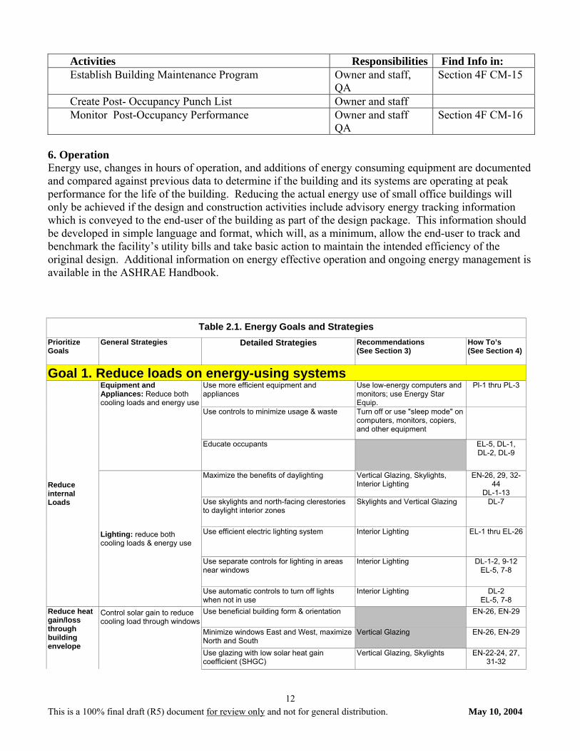
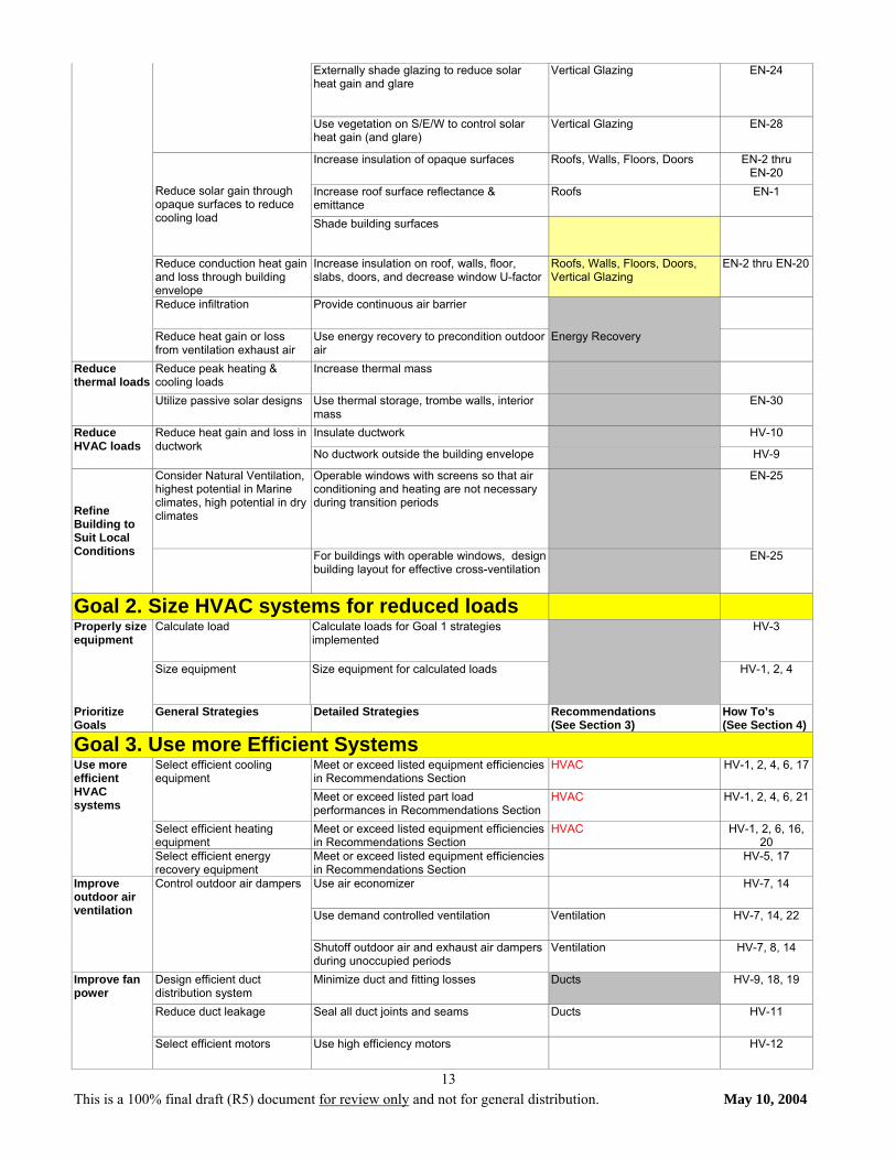
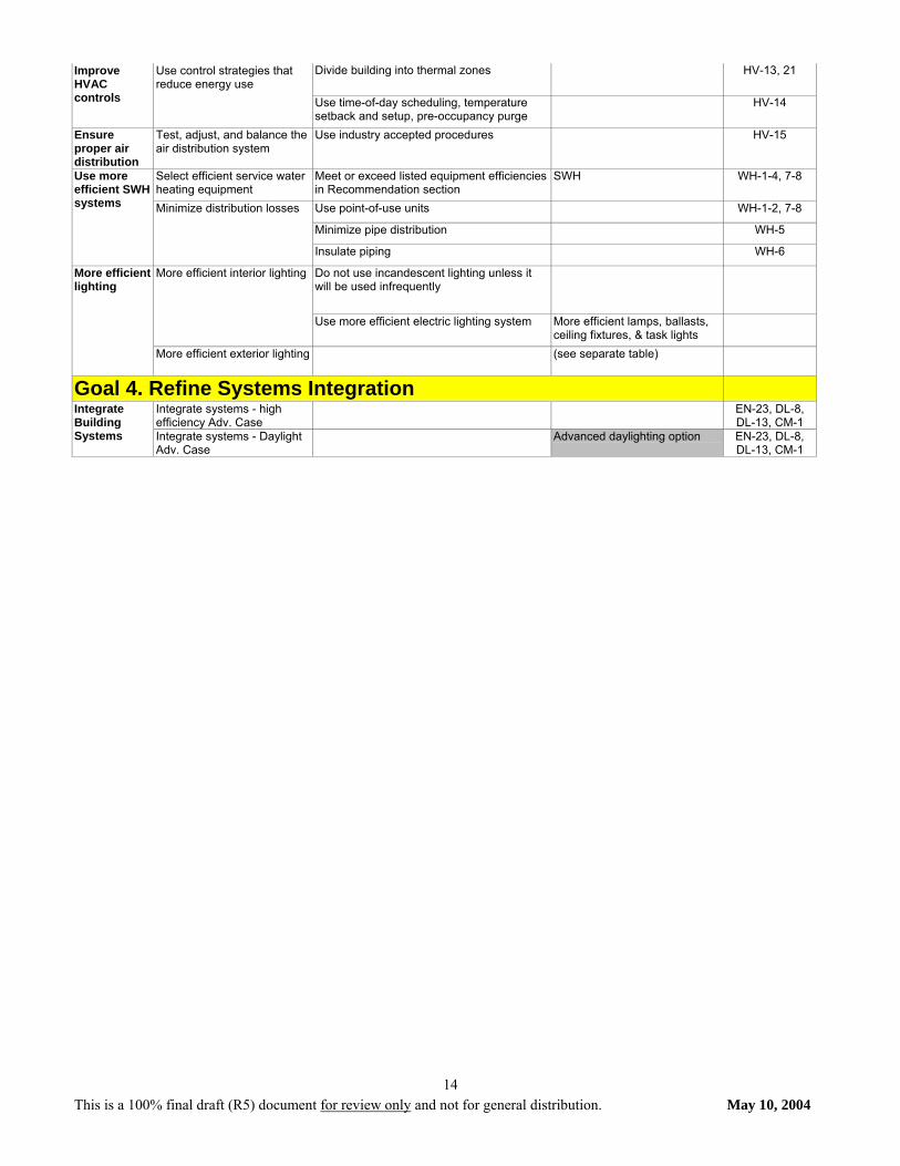
6. Operation Energy use, changes in hours of operation, and additions of energy consuming equipment are documented and compared against previous data to determine if the building and its systems are operating at peak performance for the life of the building. Reducing the actual energy use of small office buildings will only be achieved if the design and construction activities include advisory energy tracking information which is conveyed to the end-user of the building as part of the design package. This information should be developed in simple language and format, which will, as a minimum, allow the end-user to track and benchmark the facility’s utility bills and take basic action to maintain the intended efficiency of the original design. Additional information on energy effective operation and ongoing energy management is available in the ASHRAE Handbook.
Table 2.1. Energy Goals and Strategies Prioritize Goals
General Strategies Detailed Strategies Recommendations (See Section 3)
How To’s (See Section 4)
Goal 1. Reduce loads on energy-using systems Use more efficient equipment and appliances
Use low-energy computers and monitors; use Energy Star Equip.
Pl-1 thru PL-3
Use controls to minimize usage & waste Turn off or use "sleep mode" on computers, monitors, copiers, and other equipment
Equipment and Appliances: Reduce both cooling loads and energy use
Educate occupants EL-5, DL-1, DL-2, DL-9
Maximize the benefits of daylighting Vertical Glazing, Skylights, Interior Lighting
EN-26, 29, 32-44
DL-1-13 Use skylights and north-facing clerestories to daylight interior zones
Skylights and Vertical Glazing DL-7
Use efficient electric lighting system Interior Lighting EL-1 thru EL-26
Use separate controls for lighting in areas near windows
Interior Lighting DL-1-2, 9-12 EL-5, 7-8
Reduce internal Loads
Lighting: reduce both cooling loads & energy use
Use automatic controls to turn off lights when not in use
Interior Lighting DL-2 EL-5, 7-8
Use beneficial building form & orientation EN-26, EN-29
Minimize windows East and West, maximize North and South
Vertical Glazing EN-26, EN-29
Reduce heat gain/loss through building envelope
Control solar gain to reduce cooling load through windows
Use glazing with low solar heat gain coefficient (SHGC)
Vertical Glazing, Skylights EN-22-24, 27, 31-32
This is a 100% final draft (R5) document for review only and not for general distribution. May 10, 2004
13
Externally shade glazing to reduce solar heat gain and glare
Vertical Glazing EN-24
Use vegetation on S/E/W to control solar heat gain (and glare)
Vertical Glazing EN-28
Increase insulation of opaque surfaces Roofs, Walls, Floors, Doors EN-2 thru EN-20
Increase roof surface reflectance & emittance
Roofs EN-1 Reduce solar gain through opaque surfaces to reduce cooling load Shade building surfaces
Reduce conduction heat gain and loss through building envelope
Increase insulation on roof, walls, floor, slabs, doors, and decrease window U-factor
Roofs, Walls, Floors, Doors, Vertical Glazing
EN-2 thru EN-20
Reduce infiltration Provide continuous air barrier
Reduce heat gain or loss from ventilation exhaust air
Use energy recovery to precondition outdoor air
Energy Recovery
Reduce peak heating & cooling loads
Increase thermal mass Reduce thermal loads
Utilize passive solar designs Use thermal storage, trombe walls, interior mass
EN-30
Insulate ductwork HV-10 Reduce HVAC loads
Reduce heat gain and loss in ductwork
No ductwork outside the building envelope HV-9
Consider Natural Ventilation, highest potential in Marine climates, high potential in dry climates
Operable windows with screens so that air conditioning and heating are not necessary during transition periods
EN-25
Refine Building to Suit Local Conditions For buildings with operable windows, design
building layout for effective cross-ventilation EN-25
Goal 2. Size HVAC systems for reduced loads Calculate load Calculate loads for Goal 1 strategies
implemented HV-3 Properly size
equipment
Size equipment Size equipment for calculated loads HV-1, 2, 4
Prioritize Goals
General Strategies Detailed Strategies Recommendations (See Section 3)
How To’s (See Section 4)
Goal 3. Use more Efficient Systems Meet or exceed listed equipment efficiencies in Recommendations Section
HVAC HV-1, 2, 4, 6, 17 Select efficient cooling equipment
Meet or exceed listed part load performances in Recommendations Section
HVAC HV-1, 2, 4, 6, 21
Select efficient heating equipment
Meet or exceed listed equipment efficiencies in Recommendations Section
HVAC HV-1, 2, 6, 16, 20
Use more efficient HVAC systems
Select efficient energy recovery equipment
Meet or exceed listed equipment efficiencies in Recommendations Section
HV-5, 17
Use air economizer HV-7, 14
Use demand controlled ventilation Ventilation HV-7, 14, 22
Improve outdoor air ventilation
Control outdoor air dampers
Shutoff outdoor air and exhaust air dampers during unoccupied periods
Ventilation HV-7, 8, 14
Design efficient duct distribution system
Minimize duct and fitting losses Ducts HV-9, 18, 19
Reduce duct leakage Seal all duct joints and seams Ducts HV-11
Improve fan power
Select efficient motors Use high efficiency motors HV-12
This is a 100% final draft (R5) document for review only and not for general distribution. May 10, 2004
14
Divide building into thermal zones HV-13, 21 Improve HVAC controls
Use control strategies that reduce energy use
Use time-of-day scheduling, temperature setback and setup, pre-occupancy purge
HV-14
Ensure proper air distribution
Test, adjust, and balance the air distribution system
Use industry accepted procedures HV-15
Select efficient service water heating equipment
Meet or exceed listed equipment efficiencies in Recommendation section
SWH WH-1-4, 7-8
Use point-of-use units WH-1-2, 7-8
Minimize pipe distribution WH-5
Use more efficient SWH systems Minimize distribution losses
Insulate piping WH-6
Do not use incandescent lighting unless it will be used infrequently
More efficient interior lighting
Use more efficient electric lighting system More efficient lamps, ballasts, ceiling fixtures, & task lights
More efficient lighting
More efficient exterior lighting (see separate table)
Goal 4. Refine Systems Integration Integrate systems - high efficiency Adv. Case
EN-23, DL-8, DL-13, CM-1
Integrate Building Systems Integrate systems - Daylight
Adv. Case Advanced daylighting option EN-23, DL-8,
DL-13, CM-1
This is a 100% final draft (R5) document for review only and not for general distribution. May 10, 2004
15
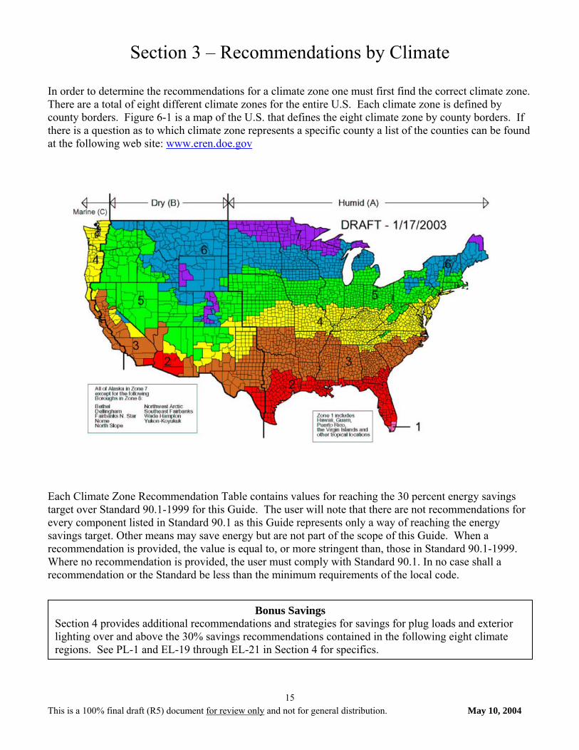
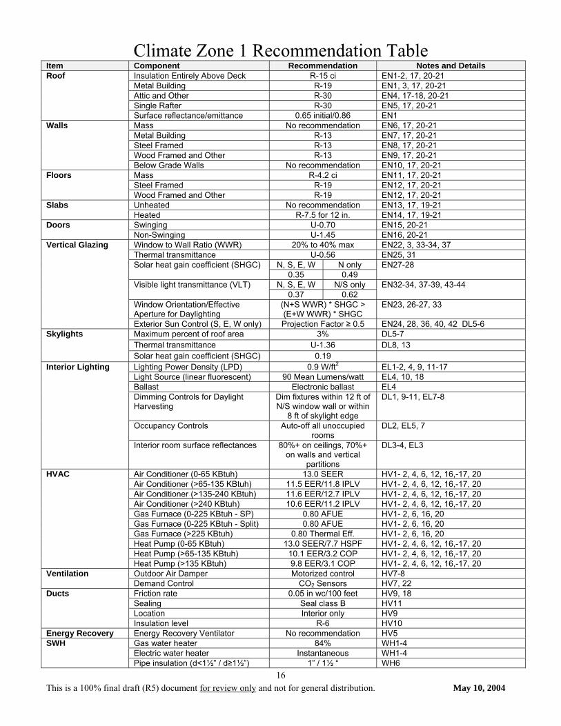
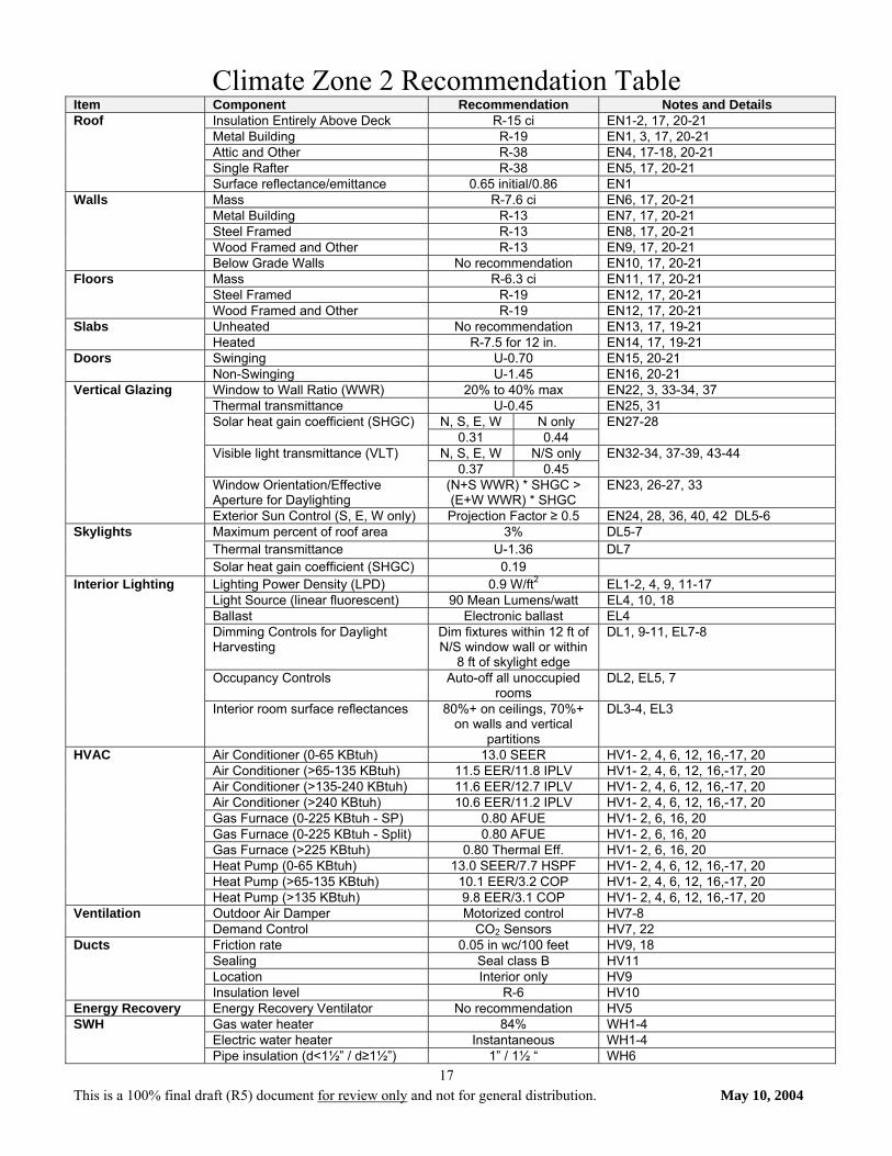
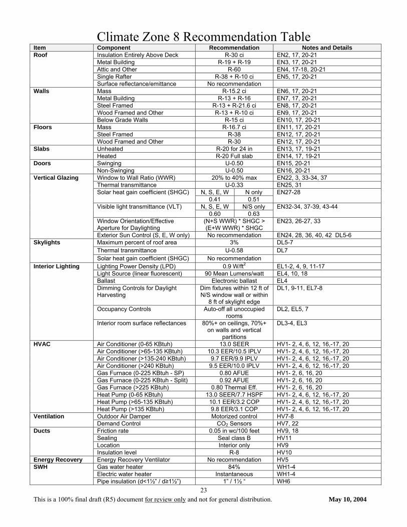
Section 3 – Recommendations by Climate In order to determine the recommendations for a climate zone one must first find the correct climate zone. There are a total of eight different climate zones for the entire U.S. Each climate zone is defined by county borders. Figure 6-1 is a map of the U.S. that defines the eight climate zone by county borders. If there is a question as to which climate zone represents a specific county a list of the counties can be found at the following web site: www.eren.doe.gov
Each Climate Zone Recommendation Table contains values for reaching the 30 percent energy savings target over Standard 90.1-1999 for this Guide. The user will note that there are not recommendations for every component listed in Standard 90.1 as this Guide represents only a way of reaching the energy savings target. Other means may save energy but are not part of the scope of this Guide. When a recommendation is provided, the value is equal to, or more stringent than, those in Standard 90.1-1999. Where no recommendation is provided, the user must comply with Standard 90.1. In no case shall a recommendation or the Standard be less than the minimum requirements of the local code.
Bonus Savings Section 4 provides additional recommendations and strategies for savings for plug loads and exterior lighting over and above the 30% savings recommendations contained in the following eight climate regions. See PL-1 and EL-19 through EL-21 in Section 4 for specifics.
This is a 100% final draft (R5) document for review only and not for general distribution. May 10, 2004
16
Climate Zone 1 Recommendation Table Item Component Recommendation Notes and Details
Insulation Entirely Above Deck R-15 ci EN1-2, 17, 20-21 Metal Building R-19 EN1, 3, 17, 20-21 Attic and Other R-30 EN4, 17-18, 20-21 Single Rafter R-30 EN5, 17, 20-21
Roof
Surface reflectance/emittance 0.65 initial/0.86 EN1 Mass No recommendation EN6, 17, 20-21 Metal Building R-13 EN7, 17, 20-21 Steel Framed R-13 EN8, 17, 20-21 Wood Framed and Other R-13 EN9, 17, 20-21
Walls
Below Grade Walls No recommendation EN10, 17, 20-21 Mass R-4.2 ci EN11, 17, 20-21 Steel Framed R-19 EN12, 17, 20-21
Floors
Wood Framed and Other R-19 EN12, 17, 20-21 Unheated No recommendation EN13, 17, 19-21 Slabs Heated R-7.5 for 12 in. EN14, 17, 19-21 Swinging U-0.70 EN15, 20-21 Doors Non-Swinging U-1.45 EN16, 20-21 Window to Wall Ratio (WWR) 20% to 40% max EN22, 3, 33-34, 37 Thermal transmittance U-0.56 EN25, 31
N, S, E, W N only Solar heat gain coefficient (SHGC) 0.35 0.49
EN27-28
N, S, E, W N/S only Visible light transmittance (VLT) 0.37 0.62
EN32-34, 37-39, 43-44
Window Orientation/Effective Aperture for Daylighting
(N+S WWR) * SHGC > (E+W WWR) * SHGC
EN23, 26-27, 33
Vertical Glazing
Exterior Sun Control (S, E, W only) Projection Factor ≥ 0.5 EN24, 28, 36, 40, 42 DL5-6 Maximum percent of roof area 3% DL5-7 Thermal transmittance U-1.36 DL8, 13
Skylights
Solar heat gain coefficient (SHGC) 0.19 Lighting Power Density (LPD) 0.9 W/ft2 EL1-2, 4, 9, 11-17 Light Source (linear fluorescent) 90 Mean Lumens/watt EL4, 10, 18 Ballast Electronic ballast EL4 Dimming Controls for Daylight Harvesting
Dim fixtures within 12 ft of N/S window wall or within
8 ft of skylight edge
DL1, 9-11, EL7-8
Occupancy Controls Auto-off all unoccupied rooms
DL2, EL5, 7
Interior Lighting
Interior room surface reflectances 80%+ on ceilings, 70%+ on walls and vertical
partitions
DL3-4, EL3
Air Conditioner (0-65 KBtuh) 13.0 SEER HV1- 2, 4, 6, 12, 16,-17, 20 Air Conditioner (>65-135 KBtuh) 11.5 EER/11.8 IPLV HV1- 2, 4, 6, 12, 16,-17, 20 Air Conditioner (>135-240 KBtuh) 11.6 EER/12.7 IPLV HV1- 2, 4, 6, 12, 16,-17, 20 Air Conditioner (>240 KBtuh) 10.6 EER/11.2 IPLV HV1- 2, 4, 6, 12, 16,-17, 20 Gas Furnace (0-225 KBtuh - SP) 0.80 AFUE HV1- 2, 6, 16, 20 Gas Furnace (0-225 KBtuh - Split) 0.80 AFUE HV1- 2, 6, 16, 20 Gas Furnace (>225 KBtuh) 0.80 Thermal Eff. HV1- 2, 6, 16, 20 Heat Pump (0-65 KBtuh) 13.0 SEER/7.7 HSPF HV1- 2, 4, 6, 12, 16,-17, 20 Heat Pump (>65-135 KBtuh) 10.1 EER/3.2 COP HV1- 2, 4, 6, 12, 16,-17, 20
HVAC
Heat Pump (>135 KBtuh) 9.8 EER/3.1 COP HV1- 2, 4, 6, 12, 16,-17, 20 Outdoor Air Damper Motorized control HV7-8 Ventilation Demand Control CO2 Sensors HV7, 22 Friction rate 0.05 in wc/100 feet HV9, 18 Sealing Seal class B HV11 Location Interior only HV9
Ducts
Insulation level R-6 HV10 Energy Recovery Energy Recovery Ventilator No recommendation HV5
Gas water heater 84% WH1-4 Electric water heater Instantaneous WH1-4
SWH
Pipe insulation (d<1½” / d≥1½”) 1” / 1½ “ WH6
This is a 100% final draft (R5) document for review only and not for general distribution. May 10, 2004
17
Climate Zone 2 Recommendation Table Item Component Recommendation Notes and Details
Insulation Entirely Above Deck R-15 ci EN1-2, 17, 20-21 Metal Building R-19 EN1, 3, 17, 20-21 Attic and Other R-38 EN4, 17-18, 20-21 Single Rafter R-38 EN5, 17, 20-21
Roof
Surface reflectance/emittance 0.65 initial/0.86 EN1 Mass R-7.6 ci EN6, 17, 20-21 Metal Building R-13 EN7, 17, 20-21 Steel Framed R-13 EN8, 17, 20-21 Wood Framed and Other R-13 EN9, 17, 20-21
Walls
Below Grade Walls No recommendation EN10, 17, 20-21 Mass R-6.3 ci EN11, 17, 20-21 Steel Framed R-19 EN12, 17, 20-21
Floors
Wood Framed and Other R-19 EN12, 17, 20-21 Unheated No recommendation EN13, 17, 19-21 Slabs Heated R-7.5 for 12 in. EN14, 17, 19-21 Swinging U-0.70 EN15, 20-21 Doors Non-Swinging U-1.45 EN16, 20-21 Window to Wall Ratio (WWR) 20% to 40% max EN22, 3, 33-34, 37 Thermal transmittance U-0.45 EN25, 31
N, S, E, W N only Solar heat gain coefficient (SHGC) 0.31 0.44
EN27-28
N, S, E, W N/S only Visible light transmittance (VLT) 0.37 0.45
EN32-34, 37-39, 43-44
Window Orientation/Effective Aperture for Daylighting
(N+S WWR) * SHGC > (E+W WWR) * SHGC
EN23, 26-27, 33
Vertical Glazing
Exterior Sun Control (S, E, W only) Projection Factor ≥ 0.5 EN24, 28, 36, 40, 42 DL5-6 Maximum percent of roof area 3% DL5-7 Thermal transmittance U-1.36 DL7
Skylights
Solar heat gain coefficient (SHGC) 0.19 Lighting Power Density (LPD) 0.9 W/ft2 EL1-2, 4, 9, 11-17 Light Source (linear fluorescent) 90 Mean Lumens/watt EL4, 10, 18 Ballast Electronic ballast EL4 Dimming Controls for Daylight Harvesting
Dim fixtures within 12 ft of N/S window wall or within
8 ft of skylight edge
DL1, 9-11, EL7-8
Occupancy Controls Auto-off all unoccupied rooms
DL2, EL5, 7
Interior Lighting
Interior room surface reflectances 80%+ on ceilings, 70%+ on walls and vertical
partitions
DL3-4, EL3
Air Conditioner (0-65 KBtuh) 13.0 SEER HV1- 2, 4, 6, 12, 16,-17, 20 Air Conditioner (>65-135 KBtuh) 11.5 EER/11.8 IPLV HV1- 2, 4, 6, 12, 16,-17, 20 Air Conditioner (>135-240 KBtuh) 11.6 EER/12.7 IPLV HV1- 2, 4, 6, 12, 16,-17, 20 Air Conditioner (>240 KBtuh) 10.6 EER/11.2 IPLV HV1- 2, 4, 6, 12, 16,-17, 20 Gas Furnace (0-225 KBtuh - SP) 0.80 AFUE HV1- 2, 6, 16, 20 Gas Furnace (0-225 KBtuh - Split) 0.80 AFUE HV1- 2, 6, 16, 20 Gas Furnace (>225 KBtuh) 0.80 Thermal Eff. HV1- 2, 6, 16, 20 Heat Pump (0-65 KBtuh) 13.0 SEER/7.7 HSPF HV1- 2, 4, 6, 12, 16,-17, 20 Heat Pump (>65-135 KBtuh) 10.1 EER/3.2 COP HV1- 2, 4, 6, 12, 16,-17, 20
HVAC
Heat Pump (>135 KBtuh) 9.8 EER/3.1 COP HV1- 2, 4, 6, 12, 16,-17, 20 Outdoor Air Damper Motorized control HV7-8 Ventilation Demand Control CO2 Sensors HV7, 22 Friction rate 0.05 in wc/100 feet HV9, 18 Sealing Seal class B HV11 Location Interior only HV9
Ducts
Insulation level R-6 HV10 Energy Recovery Energy Recovery Ventilator No recommendation HV5
Gas water heater 84% WH1-4 Electric water heater Instantaneous WH1-4
SWH
Pipe insulation (d<1½” / d≥1½”) 1” / 1½ “ WH6

This is a 100% final draft (R5) document for review only and not for general distribution. May 10, 2004
18
Climate Zone 3 Recommendation Table Item Component Recommendation Notes and Details
Insulation Entirely Above Deck R-20 ci EN1-2, 17, 20-21 Metal Building R-13 + R-13 EN1, 3, 17, 20-21 Attic and Other R-38 EN4, 17-18, 20-21 Single Rafter R-38 EN5, 17, 20-21
Roof
Surface reflectance/emittance 0.65 initial/0.86 EN1 Mass R-9.5 ci EN6, 17, 20-21 Metal Building R-13 EN7, 17, 20-21 Steel Framed R-13 + R-3.8 ci EN8, 17, 20-21 Wood Framed and Other R-13 EN9, 17, 20-21
Walls
Below Grade Walls No recommendation EN10, 17, 20-21 Mass R-8.3 ci EN11, 17, 20-21 Steel Framed R-19 EN12, 17, 20-21
Floors
Wood Framed and Other R-30 EN12, 17, 20-21 Unheated No recommendation EN13, 17, 19-21 Slabs Heated R-7.5 for 12 in. EN14, 17, 19-21 Swinging U-0.70 EN15, 20-21 Doors Non-Swinging U-1.45 EN16, 20-21 Window to Wall Ratio (WWR) 20% to 40% max EN22, 3, 33-34, 37 Thermal transmittance U-0.45 EN25, 31
N, S, E, W N only Solar heat gain coefficient (SHGC) 0.31 0.46
EN27-28
N, S, E, W N/S only Visible light transmittance (VLT) 0.37 0.62
EN32-34, 37-39, 43-44
Window Orientation/Effective Aperture for Daylighting
(N+S WWR) * SHGC > (E+W WWR) * SHGC
EN23, 26-27, 33
Vertical Glazing
Exterior Sun Control (S, E, W only) Projection Factor ≥ 0.5 EN24, 28, 36, 40, 42 DL5-6 Maximum percent of roof area 3% DL5-7 Thermal transmittance U-0.69 DL7
Skylights
Solar heat gain coefficient (SHGC) 0.19 Lighting Power Density (LPD) 0.9 W/ft2 EL1-2, 4, 9, 11-17 Light Source (linear fluorescent) 90 Mean Lumens/watt EL4, 10, 18 Ballast Electronic ballast EL4 Dimming Controls for Daylight Harvesting
Dim fixtures within 12 ft of N/S window wall or within
8 ft of skylight edge
DL1, 9-11, EL7-8
Occupancy Controls Auto-off all unoccupied rooms
DL2, EL5, 7
Interior Lighting
Interior room surface reflectances 80%+ on ceilings, 70%+ on walls and vertical
partitions
DL3-4, EL3
Air Conditioner (0-65 KBtuh) 13.0 SEER HV1- 2, 4, 6, 12, 16,-17, 20 Air Conditioner (>65-135 KBtuh) 11.5 EER/11.8 IPLV HV1- 2, 4, 6, 12, 16,-17, 20 Air Conditioner (>135-240 KBtuh) 11.6 EER/12.7 IPLV HV1- 2, 4, 6, 12, 16,-17, 20 Air Conditioner (>240 KBtuh) 10.6 EER/11.2 IPLV HV1- 2, 4, 6, 12, 16,-17, 20 Gas Furnace (0-225 KBtuh - SP) 0.80 AFUE HV1- 2, 6, 16, 20 Gas Furnace (0-225 KBtuh - Split) 0.80 AFUE HV1- 2, 6, 16, 20 Gas Furnace (>225 KBtuh) 0.80 Thermal Eff. HV1- 2, 6, 16, 20 Heat Pump (0-65 KBtuh) 13.0 SEER/7.7 HSPF HV1- 2, 4, 6, 12, 16,-17, 20 Heat Pump (>65-135 KBtuh) 10.1 EER/3.2 COP HV1- 2, 4, 6, 12, 16,-17, 20
HVAC
Heat Pump (>135 KBtuh) 9.8 EER/3.1 COP HV1- 2, 4, 6, 12, 16,-17, 20 Outdoor Air Damper Motorized control HV7-8 Ventilation Demand Control CO2 Sensors HV7, 22 Friction rate 0.05 in wc/100 feet HV9, 18 Sealing Seal class B HV11 Location Interior only HV9
Ducts
Insulation level R-6 HV10 Energy Recovery Energy Recovery Ventilator No recommendation HV5
Gas water heater 84% WH1-4 Electric water heater Instantaneous WH1-4
SWH
Pipe insulation (d<1½” / d≥1½”) 1” / 1½ “ WH6

This is a 100% final draft (R5) document for review only and not for general distribution. May 10, 2004
19
Climate Zone 4 Recommendation Table Item Component Recommendation Notes and Details
Insulation Entirely Above Deck R-20 ci EN2, 17, 20-21 Metal Building R-13 + R-19 EN3, 17, 20-21 Attic and Other R-38 EN4, 17-18, 20-21 Single Rafter R-38 EN5, 17, 20-21
Roof
Surface reflectance/emittance No recommendation Mass R-11.4 ci EN6, 17, 20-21 Metal Building R-13 EN7, 17, 20-21 Steel Framed R-13 + R-7.5 ci EN8, 17, 20-21 Wood Framed and Other R-13 EN9, 17, 20-21
Walls
Below Grade Walls No recommendation EN10, 17, 20-21 Mass R-8.3 ci EN11, 17, 20-21 Steel Framed R-30 EN12, 17, 20-21
Floors
Wood Framed and Other R-30 EN12, 17, 20-21 Unheated No recommendation EN13, 17, 19-21 Slabs Heated R-7.5 for 24 in. EN14, 17, 19-21 Swinging U-0.70 EN15, 20-21 Doors Non-Swinging U-0.50 EN16, 20-21 Window to Wall Ratio (WWR) 20% to 40% max EN22, 3, 33-34, 37 Thermal transmittance U-0.42 EN25, 31
N, S, E, W N only Solar heat gain coefficient (SHGC) 0.46 0.46
EN27-28
N, S, E, W N/S only Visible light transmittance (VLT) 0.62 0.62
EN32-34, 37-39, 43-44
Window Orientation/Effective Aperture for Daylighting
(N+S WWR) * SHGC > (E+W WWR) * SHGC
EN23, 26-27, 33
Vertical Glazing
Exterior Sun Control (S, E, W only) Projection Factor ≥ 0.5 EN24, 28, 36, 40, 42 DL5-6 Maximum percent of roof area 3% DL5-7 Thermal transmittance U-0.69 DL7
Skylights
Solar heat gain coefficient (SHGC) 0.34 Lighting Power Density (LPD) 0.9 W/ft2 EL1-2, 4, 9, 11-17 Light Source (linear fluorescent) 90 Mean Lumens/watt EL4, 10, 18 Ballast Electronic ballast EL4 Dimming Controls for Daylight Harvesting
Dim fixtures within 12 ft of N/S window wall or within
8 ft of skylight edge
DL1, 9-11, EL7-8
Occupancy Controls Auto-off all unoccupied rooms
DL2, EL5, 7
Interior Lighting
Interior room surface reflectances 80%+ on ceilings, 70%+ on walls and vertical
partitions
DL3-4, EL3
Air Conditioner (0-65 KBtuh) 13.0 SEER HV1- 2, 4, 6, 12, 16,-17, 20 Air Conditioner (>65-135 KBtuh) 10.8 EER/10.9 IPLV HV1- 2, 4, 6, 12, 16,-17, 20 Air Conditioner (>135-240 KBtuh) 10.5 EER/11.1 IPLV HV1- 2, 4, 6, 12, 16,-17, 20 Air Conditioner (>240 KBtuh) 10.0 EER/10.4 IPLV HV1- 2, 4, 6, 12, 16,-17, 20 Gas Furnace (0-225 KBtuh - SP) 0.80 AFUE HV1- 2, 6, 16, 20 Gas Furnace (0-225 KBtuh - Split) 0.80 AFUE HV1- 2, 6, 16, 20 Gas Furnace (>225 KBtuh) 0.80 Thermal Eff. HV1- 2, 6, 16, 20 Heat Pump (0-65 KBtuh) 13.0 SEER/7.7 HSPF HV1- 2, 4, 6, 12, 16,-17, 20 Heat Pump (>65-135 KBtuh) 10.1 EER/3.2 COP HV1- 2, 4, 6, 12, 16,-17, 20
HVAC
Heat Pump (>135 KBtuh) 9.8 EER/3.1 COP HV1- 2, 4, 6, 12, 16,-17, 20 Outdoor Air Damper Motorized control HV7-8 Ventilation Demand Control CO2 Sensors HV7, 22 Friction rate 0.05 in wc/100 feet HV9, 18 Sealing Seal class B HV11 Location Interior only HV9
Ducts
Insulation level R-6 HV10 Energy Recovery Energy Recovery Ventilator No recommendation HV5
Gas water heater 84% WH1-4 Electric water heater Instantaneous WH1-4
SWH
Pipe insulation (d<1½” / d≥1½”) 1” / 1½ “ WH6

This is a 100% final draft (R5) document for review only and not for general distribution. May 10, 2004
20
Climate Zone 5 Recommendation Table Item Component Recommendation Notes and Details
Insulation Entirely Above Deck R-20 ci EN2, 17, 20-21 Metal Building R-13 + R-19 EN3, 17, 20-21 Attic and Other R-38 EN4, 17-18, 20-21 Single Rafter R-38 + R-5 ci EN5, 17, 20-21
Roof
Surface reflectance/emittance No recommendation Mass R-11.4 ci EN6, 17, 20-21 Metal Building R-13 + R-13 EN7, 17, 20-21 Steel Framed R-13 + R-7.5 ci EN8, 17, 20-21 Wood Framed and Other R-13 + R-3.8 ci EN9, 17, 20-21
Walls
Below Grade Walls R-7.5 ci EN10, 17, 20-21 Mass R-10.4 ci EN11, 17, 20-21 Steel Framed R-30 EN12, 17, 20-21
Floors
Wood Framed and Other R-30 EN12, 17, 20-21 Unheated No recommendation EN13, 17, 19-21 Slabs Heated R-10 for 36 in. EN14, 17, 19-21 Swinging U-0.70 EN15, 20-21 Doors Non-Swinging U-0.50 EN16, 20-21 Window to Wall Ratio (WWR) 20% to 40% max EN22, 3, 33-34, 37 Thermal transmittance U-0.42 EN25, 31
N, S, E, W N only Solar heat gain coefficient (SHGC) 0.46 0.46
EN27-28
N, S, E, W N/S only Visible light transmittance (VLT) 0.62 0.62
EN32-34, 37-39, 43-44
Window Orientation/Effective Aperture for Daylighting
(N+S WWR) * SHGC > (E+W WWR) * SHGC
EN23, 26-27, 33
Vertical Glazing
Exterior Sun Control (S, E, W only) Projection Factor ≥ 0.5 EN24, 28, 36, 40, 42 DL5-6 Maximum percent of roof area 3% DL5-7 Thermal transmittance U-0.69 DL7
Skylights
Solar heat gain coefficient (SHGC) 0.39 Lighting Power Density (LPD) 0.9 W/ft2 EL1-2, 4, 9, 11-17 Light Source (linear fluorescent) 90 Mean Lumens/watt EL4, 10, 18 Ballast Electronic ballast EL4 Dimming Controls for Daylight Harvesting
Dim fixtures within 12 ft of N/S window wall or within
8 ft of skylight edge
DL1, 9-11, EL7-8
Occupancy Controls Auto-off all unoccupied rooms
DL2, EL5, 7
Interior Lighting
Interior room surface reflectances 80%+ on ceilings, 70%+ on walls and vertical
partitions
DL3-4, EL3
Air Conditioner (0-65 KBtuh) 13.0 SEER HV1- 2, 4, 6, 12, 16,-17, 20 Air Conditioner (>65-135 KBtuh) 10.8 EER/10.9 IPLV HV1- 2, 4, 6, 12, 16,-17, 20 Air Conditioner (>135-240 KBtuh) 10.5 EER/11.1 IPLV HV1- 2, 4, 6, 12, 16,-17, 20 Air Conditioner (>240 KBtuh) 10.0 EER/10.4 IPLV HV1- 2, 4, 6, 12, 16,-17, 20 Gas Furnace (0-225 KBtuh - SP) 0.80 AFUE HV1- 2, 6, 16, 20 Gas Furnace (0-225 KBtuh - Split) 0.80 AFUE HV1- 2, 6, 16, 20 Gas Furnace (>225 KBtuh) 0.80 Thermal Eff. HV1- 2, 6, 16, 20 Heat Pump (0-65 KBtuh) 13.0 SEER/7.7 HSPF HV1- 2, 4, 6, 12, 16,-17, 20 Heat Pump (>65-135 KBtuh) 10.1 EER/3.2 COP HV1- 2, 4, 6, 12, 16,-17, 20
HVAC
Heat Pump (>135 KBtuh) 9.8 EER/3.1 COP HV1- 2, 4, 6, 12, 16,-17, 20 Outdoor Air Damper Motorized control HV7-8 Ventilation Demand Control CO2 Sensors HV7, 22 Friction rate 0.05 in wc/100 feet HV9, 18 Sealing Seal class B HV11 Location Interior only HV9
Ducts
Insulation level R-6 HV10 Energy Recovery Energy Recovery Ventilator No recommendation HV5
Gas water heater 84% WH1-4 Electric water heater Instantaneous WH1-4
SWH
Pipe insulation (d<1½” / d≥1½”) 1” / 1½ “ WH6

This is a 100% final draft (R5) document for review only and not for general distribution. May 10, 2004
21
Climate Zone 6 Recommendation Table Item Component Recommendation Notes and Details
Insulation Entirely Above Deck R-20 ci EN2, 17, 20-21 Metal Building R-13 + R-19 EN3, 17, 20-21 Attic and Other R-38 EN4, 17-18, 20-21 Single Rafter R-38 + R-5 ci EN5, 17, 20-21
Roof
Surface reflectance/emittance No recommendation Mass R-11.4 ci EN6, 17, 20-21 Metal Building R-13 + R-13 EN7, 17, 20-21 Steel Framed R-13 + R-7.5 ci EN8, 17, 20-21 Wood Framed and Other R-13 + R-3.8 ci EN9, 17, 20-21
Walls
Below Grade Walls R-7.5 ci EN10, 17, 20-21 Mass R-10.4 ci EN11, 17, 20-21 Steel Framed R-30 EN12, 17, 20-21
Floors
Wood Framed and Other R-30 EN12, 17, 20-21 Unheated R-10 for 24 in EN13, 17, 19-21 Slabs Heated R-10 for 36 in. EN14, 17, 19-21 Swinging U-0.70 EN15, 20-21 Doors Non-Swinging U-0.50 EN16, 20-21 Window to Wall Ratio (WWR) 20% to 40% max EN22, 3, 33-34, 37 Thermal transmittance U-0.42 EN25, 31
N, S, E, W N only Solar heat gain coefficient (SHGC) 0.46 0.46
EN27-28
N, S, E, W N/S only Visible light transmittance (VLT) 0.62 0.62
EN32-34, 37-39, 43-44
Window Orientation/Effective Aperture for Daylighting
(N+S WWR) * SHGC > (E+W WWR) * SHGC
EN23, 26-27, 33
Vertical Glazing
Exterior Sun Control (S, E, W only) No recommendation EN24, 28, 36, 40, 42 DL5-6 Maximum percent of roof area 3% DL5-7 Thermal transmittance U-0.69 DL7
Skylights
Solar heat gain coefficient (SHGC) 0.49 Lighting Power Density (LPD) 0.9 W/ft2 EL1-2, 4, 9, 11-17 Light Source (linear fluorescent) 90 Mean Lumens/watt EL4, 10, 18 Ballast Electronic ballast EL4 Dimming Controls for Daylight Harvesting
Dim fixtures within 12 ft of N/S window wall or within
8 ft of skylight edge
DL1, 9-11, EL7-8
Occupancy Controls Auto-off all unoccupied rooms
DL2, EL5, 7
Interior Lighting
Interior room surface reflectances 80%+ on ceilings, 70%+ on walls and vertical
partitions
DL3-4, EL3
Air Conditioner (0-65 KBtuh) 13.0 SEER HV1- 2, 4, 6, 12, 16,-17, 20 Air Conditioner (>65-135 KBtuh) 10.8 EER/10.9 IPLV HV1- 2, 4, 6, 12, 16,-17, 20 Air Conditioner (>135-240 KBtuh) 10.5 EER/11.1 IPLV HV1- 2, 4, 6, 12, 16,-17, 20 Air Conditioner (>240 KBtuh) 10.0 EER/10.4 IPLV HV1- 2, 4, 6, 12, 16,-17, 20 Gas Furnace (0-225 KBtuh - SP) 0.80 AFUE HV1- 2, 6, 16, 20 Gas Furnace (0-225 KBtuh - Split) 0.80 AFUE HV1- 2, 6, 16, 20 Gas Furnace (>225 KBtuh) 0.80 Thermal Eff. HV1- 2, 6, 16, 20 Heat Pump (0-65 KBtuh) 13.0 SEER/7.7 HSPF HV1- 2, 4, 6, 12, 16,-17, 20 Heat Pump (>65-135 KBtuh) 10.1 EER/3.2 COP HV1- 2, 4, 6, 12, 16,-17, 20
HVAC
Heat Pump (>135 KBtuh) 9.8 EER/3.1 COP HV1- 2, 4, 6, 12, 16,-17, 20 Outdoor Air Damper Motorized control HV7-8 Ventilation Demand Control CO2 Sensors HV7, 22 Friction rate 0.05 in wc/100 feet HV9, 18 Sealing Seal class B HV11 Location Interior only HV9
Ducts
Insulation level R-6 HV10 Energy Recovery Energy Recovery Ventilator No recommendation HV5
Gas water heater 84% WH1-4 Electric water heater Instantaneous WH1-4
SWH
Pipe insulation (d<1½” / d≥1½”) 1” / 1½ “ WH6

This is a 100% final draft (R5) document for review only and not for general distribution. May 10, 2004
22
Climate Zone 7 Recommendation Table Item Component Recommendation Notes and Details
Insulation Entirely Above Deck R-20 ci EN2, 17, 20-21 Metal Building R-13 + R-19 EN3, 17, 20-21 Attic and Other R-60 EN4, 17-18, 20-21 Single Rafter R-38 + R-10 ci EN5, 17, 20-21
Roof
Surface reflectance/emittance No recommendation Mass R-15.2 ci EN6, 17, 20-21 Metal Building R-13 + R-13 EN7, 17, 20-21 Steel Framed R-13 + R-7.5 ci EN8, 17, 20-21 Wood Framed and Other R-13 + R-7.5 ci EN9, 17, 20-21
Walls
Below Grade Walls R-7.5 ci EN10, 17, 20-21 Mass R-12.5 ci EN11, 17, 20-21 Steel Framed R-38 EN12, 17, 20-21
Floors
Wood Framed and Other R-30 EN12, 17, 20-21 Unheated R-15 for 24 in EN13, 17, 19-21 Slabs Heated R-15 Full slab EN14, 17, 19-21 Swinging U-0.50 EN15, 20-21 Doors Non-Swinging U-0.50 EN16, 20-21 Window to Wall Ratio (WWR) 20% to 40% max EN22, 3, 33-34, 37 Thermal transmittance U-0.33 EN25, 31
N, S, E, W N only Solar heat gain coefficient (SHGC) 0.41 0.64
EN27-28
N, S, E, W N/S only Visible light transmittance (VLT) 0.60 0.66
EN32-34, 37-39, 43-44
Window Orientation/Effective Aperture for Daylighting
(N+S WWR) * SHGC > (E+W WWR) * SHGC
EN23, 26-27, 33
Vertical Glazing
Exterior Sun Control (S, E, W only) No recommendation EN24, 28, 36, 40, 42 DL5-6 Maximum percent of roof area 3% DL5-7 Thermal transmittance U-0.69 DL7
Skylights
Solar heat gain coefficient (SHGC) 0.64 Lighting Power Density (LPD) 0.9 W/ft2 EL1-2, 4, 9, 11-17 Light Source (linear fluorescent) 90 Mean Lumens/watt EL4, 10, 18 Ballast Electronic ballast EL4 Dimming Controls for Daylight Harvesting
Dim fixtures within 12 ft of N/S window wall or within
8 ft of skylight edge
DL1, 9-11, EL7-8
Occupancy Controls Auto-off all unoccupied rooms
DL2, EL5, 7
Interior Lighting
Interior room surface reflectances 80%+ on ceilings, 70%+ on walls and vertical
partitions
DL3-4, EL3
Air Conditioner (0-65 KBtuh) 13.0 SEER HV1- 2, 4, 6, 12, 16,-17, 20 Air Conditioner (>65-135 KBtuh) 10.3 EER/10.5 IPLV HV1- 2, 4, 6, 12, 16,-17, 20 Air Conditioner (>135-240 KBtuh) 9.7 EER/9.9 IPLV HV1- 2, 4, 6, 12, 16,-17, 20 Air Conditioner (>240 KBtuh) 9.5 EER/10.0 IPLV HV1- 2, 4, 6, 12, 16,-17, 20 Gas Furnace (0-225 KBtuh - SP) 0.80 AFUE HV1- 2, 6, 16, 20 Gas Furnace (0-225 KBtuh - Split) 0.92 AFUE HV1- 2, 6, 16, 20 Gas Furnace (>225 KBtuh) 0.80 Thermal Eff. HV1- 2, 6, 16, 20 Heat Pump (0-65 KBtuh) 13.0 SEER/7.7 HSPF HV1- 2, 4, 6, 12, 16,-17, 20 Heat Pump (>65-135 KBtuh) 10.1 EER/3.2 COP HV1- 2, 4, 6, 12, 16,-17, 20
HVAC
Heat Pump (>135 KBtuh) 9.8 EER/3.1 COP HV1- 2, 4, 6, 12, 16,-17, 20 Outdoor Air Damper Motorized control HV7-8 Ventilation Demand Control CO2 Sensors HV7, 22 Friction rate 0.05 in wc/100 feet HV9, 18 Sealing Seal class B HV11 Location Interior only HV9
Ducts
Insulation level R-6 HV10 Energy Recovery Energy Recovery Ventilator No recommendation HV5
Gas water heater 84% WH1-4 Electric water heater Instantaneous WH1-4
SWH
Pipe insulation (d<1½” / d≥1½”) 1” / 1½ “ WH6
This is a 100% final draft (R5) document for review only and not for general distribution. May 10, 2004
23
Climate Zone 8 Recommendation Table Item Component Recommendation Notes and Details
Insulation Entirely Above Deck R-30 ci EN2, 17, 20-21 Metal Building R-19 + R-19 EN3, 17, 20-21 Attic and Other R-60 EN4, 17-18, 20-21 Single Rafter R-38 + R-10 ci EN5, 17, 20-21
Roof
Surface reflectance/emittance No recommendation Mass R-15.2 ci EN6, 17, 20-21 Metal Building R-13 + R-16 EN7, 17, 20-21 Steel Framed R-13 + R-21.6 ci EN8, 17, 20-21 Wood Framed and Other R-13 + R-10 ci EN9, 17, 20-21
Walls
Below Grade Walls R-15 ci EN10, 17, 20-21 Mass R-16.7 ci EN11, 17, 20-21 Steel Framed R-38 EN12, 17, 20-21
Floors
Wood Framed and Other R-30 EN12, 17, 20-21 Unheated R-20 for 24 in EN13, 17, 19-21 Slabs Heated R-20 Full slab EN14, 17, 19-21 Swinging U-0.50 EN15, 20-21 Doors Non-Swinging U-0.50 EN16, 20-21 Window to Wall Ratio (WWR) 20% to 40% max EN22, 3, 33-34, 37 Thermal transmittance U-0.33 EN25, 31
N, S, E, W N only Solar heat gain coefficient (SHGC) 0.41 0.51
EN27-28
N, S, E, W N/S only Visible light transmittance (VLT) 0.60 0.63
EN32-34, 37-39, 43-44
Window Orientation/Effective Aperture for Daylighting
(N+S WWR) * SHGC > (E+W WWR) * SHGC
EN23, 26-27, 33
Vertical Glazing
Exterior Sun Control (S, E, W only) No recommendation EN24, 28, 36, 40, 42 DL5-6 Maximum percent of roof area 3% DL5-7 Thermal transmittance U-0.58 DL7
Skylights
Solar heat gain coefficient (SHGC) No recommendation Lighting Power Density (LPD) 0.9 W/ft2 EL1-2, 4, 9, 11-17 Light Source (linear fluorescent) 90 Mean Lumens/watt EL4, 10, 18 Ballast Electronic ballast EL4 Dimming Controls for Daylight Harvesting
Dim fixtures within 12 ft of N/S window wall or within
8 ft of skylight edge
DL1, 9-11, EL7-8
Occupancy Controls Auto-off all unoccupied rooms
DL2, EL5, 7
Interior Lighting
Interior room surface reflectances 80%+ on ceilings, 70%+ on walls and vertical
partitions
DL3-4, EL3
Air Conditioner (0-65 KBtuh) 13.0 SEER HV1- 2, 4, 6, 12, 16,-17, 20 Air Conditioner (>65-135 KBtuh) 10.3 EER/10.5 IPLV HV1- 2, 4, 6, 12, 16,-17, 20 Air Conditioner (>135-240 KBtuh) 9.7 EER/9.9 IPLV HV1- 2, 4, 6, 12, 16,-17, 20 Air Conditioner (>240 KBtuh) 9.5 EER/10.0 IPLV HV1- 2, 4, 6, 12, 16,-17, 20 Gas Furnace (0-225 KBtuh - SP) 0.80 AFUE HV1- 2, 6, 16, 20 Gas Furnace (0-225 KBtuh - Split) 0.92 AFUE HV1- 2, 6, 16, 20 Gas Furnace (>225 KBtuh) 0.80 Thermal Eff. HV1- 2, 6, 16, 20 Heat Pump (0-65 KBtuh) 13.0 SEER/7.7 HSPF HV1- 2, 4, 6, 12, 16,-17, 20 Heat Pump (>65-135 KBtuh) 10.1 EER/3.2 COP HV1- 2, 4, 6, 12, 16,-17, 20
HVAC
Heat Pump (>135 KBtuh) 9.8 EER/3.1 COP HV1- 2, 4, 6, 12, 16,-17, 20 Outdoor Air Damper Motorized control HV7-8 Ventilation Demand Control CO2 Sensors HV7, 22 Friction rate 0.05 in wc/100 feet HV9, 18 Sealing Seal class B HV11 Location Interior only HV9
Ducts
Insulation level R-8 HV10 Energy Recovery Energy Recovery Ventilator No recommendation HV5
Gas water heater 84% WH1-4 Electric water heater Instantaneous WH1-4
SWH
Pipe insulation (d<1½” / d≥1½”) 1” / 1½ “ WH6
This is a 100% final draft (R5) document for review only and not for general distribution. May 10, 2004
24
Section 4 – How-To Implement Recommendations Recommendations are contained in the individual Tables in Section 3, Recommendations by Climate. The following information is intended to provide guidance in good practice guidance for implementing the recommendations as well as cautions to avoid known problems in energy efficient construction. • Envelope
OPAQUE ENVELOPE COMPONENTS Note that the following how-to’s address the recommendations in Chapter 3, but are not necessarily applicable to any specific construction project.
Good Design Practice (How-To) EN-1 Cool Roofs Cool roofs are recommended for roofs with insulation entirely above deck and metal building roofs. In order to be considered a cool roof for climate zones 1-3 the following conditions apply: 1. The roof has a high reflectance. The high reflectance keeps much of the sun’s energy from being absorbed.
2. The roof has a high emittance. The high emittance allows the roof to cool more rapidly.
The radiative property values should be rated by a laboratory accredited by the Cool Roof Rating Council.
Cool roofs are typically white and have a smooth texture. Commercial roofing products that qualify as cool roofs fall in two categories: single-ply and liquid applied. Examples of single-ply products include:
• White EPDM (Ethylene-Propylene-Diene-terpolymer Membrane)
• White PVC (polyvinyl chloride)
• White CPE (chlorinated polyethylene)
• White CPSE (chlorosulfonated polyethylene, e.g. Hypalon)
• White TPO (thermoplastic polyolefin)
Liquid-applied products may be used to coat a variety of substrates. Products include: • White elastomeric, polyurethane, or acrylic coatings
• White paint (on metal or concrete)
EN-2 Roofs – Insulation Entirely Above Deck The insulation entirely above deck is continuous insulation (ci) rigid boards because there are no framing members present that would introduce thermal bridges or short circuits to bypass the insulation. When two layers of continuous insulation are used in this construction, the board edges should be staggered to reduce the potential for convection losses or thermal bridging. If an inverted or protected membrane roof system is used, at least one layer of insulation is placed above the membrane while a maximum of one layer is placed beneath the membrane.
EN-3 Roofs - Metal Buildings
This is a 100% final draft (R5) document for review only and not for general distribution. May 10, 2004
25
Metal buildings pose particular challenges in the pursuit of designing and constructing advanced buildings. The metal skin and purlin/girt connection, even with compressed fiberglass between them, is highly conductive, which limits the effectiveness of the insulation. The thermal performance of metal building roofs with fiberglass batts is improved by treating the thermal bridging associated with fasteners. Use of foam blocks is a proven technique to reduce the thermal bridging. Thermal blocks, with minimum dimensions of 1 inch by 3 inches, should be R-5 rigid insulation installed parallel to the purlins. In climate zones 1 and 2, the recommended construction is R-19 insulation batts draped perpendicularly over the purlins. Thermal blocks are then placed above the purlin/batt, and the roof deck is secured to the purlins. In climate zones 3 through 8 the recommended construction is two layers of batt insulation. The first insulation batt is draped perpendicular over the purlins with enough looseness to allow the second insulation batt to be laid above it, parallel to the purlins. In the metal building industry, this is known as the “sag and bag” insulation system. (Need Figure?) Standard practice does not include an integral method of providing a sufficient air barrier. Continuous rigid insulation provides a method for tackling this issue and may be used provided the total roof assembly has a U-factor that is less than or equal to the appropriate climate zone construction listed in Appendix A. EN-4 Roofs – Attics and Other Roofs Attics and other roofs include roofs with insulation entirely below (inside of) the roof structure (i.e. attics and cathedral ceilings) and roofs with insulation both above and below the roof structure. Ventilated attic spaces need to have the insulation installed at the ceiling line. Unventilated attic spaces may have the insulation installed at the roof line. When suspended ceilings with removable ceiling tiles are used, the insulation performance is best when install at the roof line. EN-5 Roofs – Single Rafter Single rafter roofs have the roof above and ceiling below both attached to the same wood rafter and the insulation is located in the cavity created between the wood rafters. Single rafters can be constructed using solid wood framing members or truss type framing members. The insulation is installed between the wood rafters and is in intimate contact with the ceiling to avoid the potential thermal short circuiting associated with open or exposed air spaces.
EN-6 Walls – Mass Mass walls are defined as those with a heat capacity exceeding 7 Btu/ft2. Insulation may be placed either on the inside or the outside of the masonry wall. When insulation is placed on the exterior of the wall, rigid continuous insulation (ci) is recommended. When insulation is placed on the interior of the wall a furring or framing system should be used provided the total wall assembly has a U-factor that is less than or equal to the appropriate climate zone construction listed in Appendix A. The greatest advantages of mass can be obtained when insulation is placed on the exterior of the mass. In this case, the mass absorbs internal heat gains that are later released in the evenings when the buildings are not occupied.
EN-7 Walls – Metal Building
This is a 100% final draft (R5) document for review only and not for general distribution. May 10, 2004
26
In climate zones 1-4 a single layer of fiberglass batt insulation is recommended. The insulation is installed continuously perpendicular to the exterior of the girts, and is compressed as the metal skin is attached to the girts. In climate zones 5-8 two layers of fiberglass batt insulation are recommended. The first layer is installed continuously perpendicular to the exterior of the girts, and is compressed as the metal skin is attached to the girts. The second layer of insulation is installed parallel to the girts within the framing cavity. In all climate zones, rigid continuous insulation (ci) is another option provided the total wall assembly has a U-factor that is less than or equal to the appropriate climate zone construction listed in Appendix A.
EN-8 Walls – Steel Framed Cold formed steel framing members are thermal bridges to the cavity insulation. Adding exterior foam sheathing as continuous insulation (ci) is the preferred method to upgrade the wall thermal performance because it will increase the overall wall thermal performance and tends to minimize the impact of the thermal bridging. Cavity insulation is used within the steel-framed wall, while rigid continuous insulation is placed on the exterior side of the steel framing. Alternate combinations of cavity insulations and sheathings in thicker steel framed walls can be used provided the total wall assembly has a U-factor that is less than or equal to the appropriate climate zone construction listed in Appendix A. EN-9 Walls – Wood Frame and Other Cavity insulation is used within the wood-framed wall, while rigid continuous insulation (ci) is placed on the exterior side of the framing. Alternate combinations of cavity insulations and sheathings in thicker walls can be used provided the total wall assembly has a U-factor that is less than or equal to the appropriate climate zone construction listed in Appendix A. EN-10 Below Grade Walls Insulation, when recommended, may be placed either on the inside or the outside of the below grade wall. If placed on the exterior of the wall, rigid continuous insulation (ci) is recommended. If placed on the interior, a furring or framing system is recommended provided the total wall assembly has a C-factor that is less than or equal to the appropriate climate zone construction listed in Appendix A.
EN-11 Floors – Mass Insulation should be continuous and either integral to or above the slab. This can be achieved by placing high-density extruded polystyrene as continuous insulation (ci) above the slab with either plywood or a thin layer of concrete on top. Placing insulation below the deck is not recommended, due to losses through any concrete support columns or through the slab perimeter. Exception. Buildings or zones within buildings which have durable floors for heavy machinery or equipment could place insulation below the deck.
When heated slabs are placed below grade, below-grade walls should meet the insulation recommendations for perimeter insulation according to the heated slab-on-grade construction.
EN-12 Floors – Steel Joist or Wood Frame Insulation is to be installed parallel to the framing members and in intimate contact with the flooring system supported by the framing member in order to avoid the potential thermal short circuiting associated with open or exposed air spaces. Non-rigid insulation should be supported from below, no less frequently than 24 inches on center.
EN-13 Slab-on-Grade Floors, Unheated
This is a 100% final draft (R5) document for review only and not for general distribution. May 10, 2004
27
Continuous rigid insulation is used around the perimeter of the slab and should reach the depth listed in the recommendation or to the bottom of the footing, whichever is deeper. Additionally, in climate zones 7 and 8 and in cases where the frost line is deeper than the footing, continuous insulation should be placed below the slab as well.
EN-14 Slab-on-Grade Floors, Heated Continuous rigid insulation should be used around the perimeter of the slab and should reach to the depth listed or to the frost line, whichever is deeper. Additionally, in climate zones 7 and 8, continuous insulation should be placed below the slab as well. Note: In areas where termites are a concern and rigid insulation is not recommended for use under the slab, a different heating system should be used.
EN-15 Doors – Swinging A U-factor of 0.37 corresponds to an insulated double panel metal door. A U-factor of 0.61 corresponds to a double panel metal door.
EN-16 Doors – Roll-up or Sliding Roll-up or sliding doors are recommended to have R- 4.75 rigid insulation. The center of section U-factor is degraded due to thermal bridging at the door and section edges.
Options (Opaque Envelope Components)
EN- 17 Alternative Constructions
The climate zone recommendations provide only one solution for upgrading the thermal performance of the envelope. Other constructions can be equally effective but they are not specified here. Any alternative construction that is less than or equal to the U-factor, C-factor, or F-factor for the appropriate climate zone construction is equally acceptable. A table of U-factors, C-factors, and F-factors that corresponds to all of the recommendations is presented in Appendix A. Procedures to calculate U-factors and C-factors are presented in the ASHRAE Handbook of Fundamentals and expanded U-factor, C-factor and F-factor tables are presented in Standard 90.1-1999, Appendix A.
Cautions (Opaque Envelope Components) The design of building envelopes for durability, indoor environmental quality and energy conservation should not create conditions of accelerated deterioration, reduced thermal performance, or problems associated with moisture and air infiltration. The following cautions should be incorporated into the design and construction of the building. EN-18 Heel Heights When insulation levels are increased in attic spaces the heel height should be raised to avoid or at least minimize the eave compression. EN-19 Slab Edge Insulation Use of slab edge insulation improves thermal performance but problems can occur in regions of the country that have termites. EN-20 Moisture Control Building envelope assemblies should be designed to prevent wetting, high moisture content, liquid water intrusion, and condensation caused by diffusion of water vapor. EN-21 Air Infiltration Control
This is a 100% final draft (R5) document for review only and not for general distribution. May 10, 2004
28
The building envelope shall be designed and constructed with a continuous air barrier system to control air leakage into or out of the conditioned space. An air barrier system shall also be provided for interior separations between conditioned space and space designed to maintain temperature or humidity levels which differ from those in the conditioned space by more than 50% of the difference between the conditioned space and design ambient conditions. The air barrier system has the following characteristics:
1. It is continuous, with all joints made air-tight.
2. Materials used for the air barrier system have an air permeability not to exceed 0.004 cfm/ft2 under a pressure differential of 0.3 in. water (1.57psf) (0.02 L/s.m2 @ 75 Pa) when tested in accordance with ASTM E 2178.
3. It is be capable of withstanding positive and negative combined design wind, fan and stack pressures on the envelope without damage or displacement, and shall transfer the load to the structure. It shall not displace adjacent materials under full load.
4. It is durable or maintainable.
5. The air barrier material of an envelope assembly is joined in an air-tight and flexible manner to the air barrier material of adjacent assemblies, allowing for the relative movement of these assemblies and components due to thermal and moisture variations, creep and structural deflection.
6. Connections are to be made between:
a) Foundation and walls.
b) Walls and windows or doors.
c) Different wall systems.
d) Wall and roof.
e) Wall and roof over unconditioned space.
f) Walls, floor and roof across construction, control and expansion joints.
g) Walls, floors and roof to utility, pipe and duct penetrations.
All penetrations of the air barrier system and paths of air infiltration/exfiltration are to be made air-tight
VERTICAL GLAZING (ENVELOPE)
Good Design Practice (How-To) EN-22 The recommendations for vertical windows are listed in Chapter 4 by climate zone. Table 5-1 below shows the type of window construction that generally corresponds to the U-factor specifications in the Chapter 4 Recommendation Tables.
Table 5-1 Vertical Fenestration Descriptions U-factor SHGC VLT Description
0.47 0.31 0.37 Metal frame with a Thermal Break Clear Glass with Medium Performance Reflective Coating Insulated Spacers between Panes Clear Glass with Low-e Sputter Coating
0.44 0.46 0.62 Metal Frame with a Thermal Break
This is a 100% final draft (R5) document for review only and not for general distribution. May 10, 2004
29
Clear Glass Insulated Spacers between Panes Clear Glass with Low-e Sputter Coating
0.38 0.41 0.60 Vinyl Frame Clear Glass Insulated Spacers between Panes Clear Glass with Low-e Sputter
To be useful and consistent, the U-factors for windows should be measured over the entire window assembly, not just the center of glass. Look for a label that denotes the window rating is certified by the National Fenestration Rating Council (NFRC). The Window Wall Ratio (WWR) is the percentage resulting from dividing the total glazed area by the total wall area. For any given WWR selected between 20% and 40%, the recommended values for U-factor and SHGC will save 30% energy over the minimum requirements of Standard 90.1-1999. A reduction in the WWR ratio will also save energy, especially if glazing is reduced on the east and west facades. The smallest glazed area should be designed that is still consistent with needs for view, daylighting and passive solar strategies.
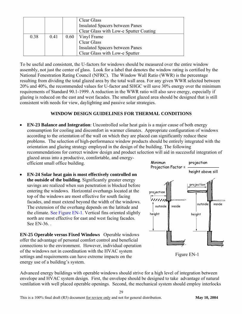
WINDOW DESIGN GUIDELINES FOR THERMAL CONDITIONS • EN-23 Balance and Integration: Uncontrolled solar heat gain is a major cause of both energy
consumption for cooling and discomfort in warmer climates. Appropriate configuration of windows according to the orientation of the wall on which they are placed can significantly reduce these problems. The selection of high-performance window products should be entirely integrated with the orientation and glazing strategy employed in the design of the building. The following recommendations for correct window design and product selection will aid in successful integration of glazed areas into a productive, comfortable, and energy-efficient small office building.
• EN-24 Solar heat gain is most effectively controlled on
the outside of the building. Significantly greater energy savings are realized when sun penetration is blocked before entering the windows. Horizontal overhangs located at the top of the windows are most effective for south facing facades, and must extend beyond the width of the windows. The extension of the overhang depends on the latitude and the climate. See Figure EN-1. Vertical fins oriented slightly north are most effective for east and west facing facades. See EN-36. .
EN-25 Operable versus Fixed Windows Operable windows offer the advantage of personal comfort control and beneficial connections to the environment. However, individual operation of the windows not in coordination with the HVAC system settings and requirements can have extreme impacts on the energy use of a building’s system. Advanced energy buildings with operable windows should strive for a high level of integration between envelope and HVAC system design. First, the envelope should be designed to take advantage of natural ventilation with well placed operable openings. Second, the mechanical system should employ interlocks
Figure EN-1
This is a 100% final draft (R5) document for review only and not for general distribution. May 10, 2004
30
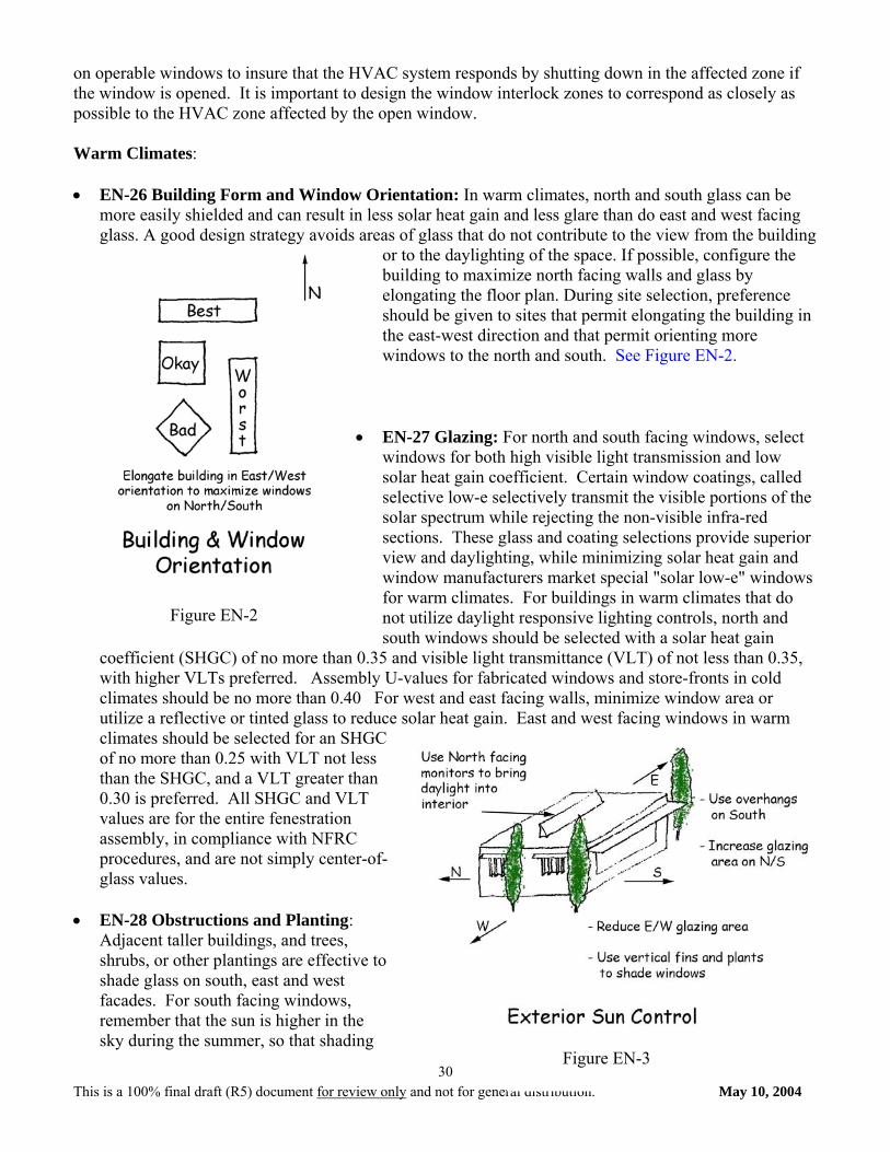
on operable windows to insure that the HVAC system responds by shutting down in the affected zone if the window is opened. It is important to design the window interlock zones to correspond as closely as possible to the HVAC zone affected by the open window. Warm Climates: • EN-26 Building Form and Window Orientation: In warm climates, north and south glass can be
more easily shielded and can result in less solar heat gain and less glare than do east and west facing glass. A good design strategy avoids areas of glass that do not contribute to the view from the building
or to the daylighting of the space. If possible, configure the building to maximize north facing walls and glass by elongating the floor plan. During site selection, preference should be given to sites that permit elongating the building in the east-west direction and that permit orienting more windows to the north and south. See Figure EN-2.
• EN-27 Glazing: For north and south facing windows, select
windows for both high visible light transmission and low solar heat gain coefficient. Certain window coatings, called selective low-e selectively transmit the visible portions of the solar spectrum while rejecting the non-visible infra-red sections. These glass and coating selections provide superior view and daylighting, while minimizing solar heat gain and window manufacturers market special "solar low-e" windows for warm climates. For buildings in warm climates that do not utilize daylight responsive lighting controls, north and south windows should be selected with a solar heat gain
coefficient (SHGC) of no more than 0.35 and visible light transmittance (VLT) of not less than 0.35, with higher VLTs preferred. Assembly U-values for fabricated windows and store-fronts in cold climates should be no more than 0.40 For west and east facing walls, minimize window area or utilize a reflective or tinted glass to reduce solar heat gain. East and west facing windows in warm climates should be selected for an SHGC of no more than 0.25 with VLT not less than the SHGC, and a VLT greater than 0.30 is preferred. All SHGC and VLT values are for the entire fenestration assembly, in compliance with NFRC procedures, and are not simply center-of-glass values.
• EN-28 Obstructions and Planting:
Adjacent taller buildings, and trees, shrubs, or other plantings are effective to shade glass on south, east and west facades. For south facing windows, remember that the sun is higher in the sky during the summer, so that shading
Figure EN-3
Figure EN-2
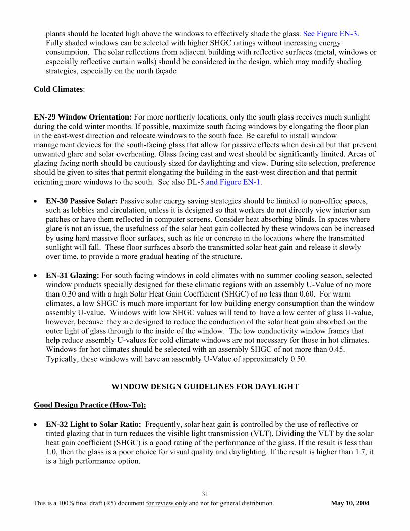
This is a 100% final draft (R5) document for review only and not for general distribution. May 10, 2004
31
plants should be located high above the windows to effectively shade the glass. See Figure EN-3. Fully shaded windows can be selected with higher SHGC ratings without increasing energy consumption. The solar reflections from adjacent building with reflective surfaces (metal, windows or especially reflective curtain walls) should be considered in the design, which may modify shading strategies, especially on the north façade
Cold Climates: EN-29 Window Orientation: For more northerly locations, only the south glass receives much sunlight during the cold winter months. If possible, maximize south facing windows by elongating the floor plan in the east-west direction and relocate windows to the south face. Be careful to install window management devices for the south-facing glass that allow for passive effects when desired but that prevent unwanted glare and solar overheating. Glass facing east and west should be significantly limited. Areas of glazing facing north should be cautiously sized for daylighting and view. During site selection, preference should be given to sites that permit elongating the building in the east-west direction and that permit orienting more windows to the south. See also DL-5.and Figure EN-1. • EN-30 Passive Solar: Passive solar energy saving strategies should be limited to non-office spaces,
such as lobbies and circulation, unless it is designed so that workers do not directly view interior sun patches or have them reflected in computer screens. Consider heat absorbing blinds. In spaces where glare is not an issue, the usefulness of the solar heat gain collected by these windows can be increased by using hard massive floor surfaces, such as tile or concrete in the locations where the transmitted sunlight will fall. These floor surfaces absorb the transmitted solar heat gain and release it slowly over time, to provide a more gradual heating of the structure.
• EN-31 Glazing: For south facing windows in cold climates with no summer cooling season, selected
window products specially designed for these climatic regions with an assembly U-Value of no more than 0.30 and with a high Solar Heat Gain Coefficient (SHGC) of no less than 0.60. For warm climates, a low SHGC is much more important for low building energy consumption than the window assembly U-value. Windows with low SHGC values will tend to have a low center of glass U-value, however, because they are designed to reduce the conduction of the solar heat gain absorbed on the outer light of glass through to the inside of the window. The low conductivity window frames that help reduce assembly U-values for cold climate windows are not necessary for those in hot climates. Windows for hot climates should be selected with an assembly SHGC of not more than 0.45. Typically, these windows will have an assembly U-Value of approximately 0.50.
WINDOW DESIGN GUIDELINES FOR DAYLIGHT Good Design Practice (How-To): • EN-32 Light to Solar Ratio: Frequently, solar heat gain is controlled by the use of reflective or
tinted glazing that in turn reduces the visible light transmission (VLT). Dividing the VLT by the solar heat gain coefficient (SHGC) is a good rating of the performance of the glass. If the result is less than 1.0, then the glass is a poor choice for visual quality and daylighting. If the result is higher than 1.7, it is a high performance option.
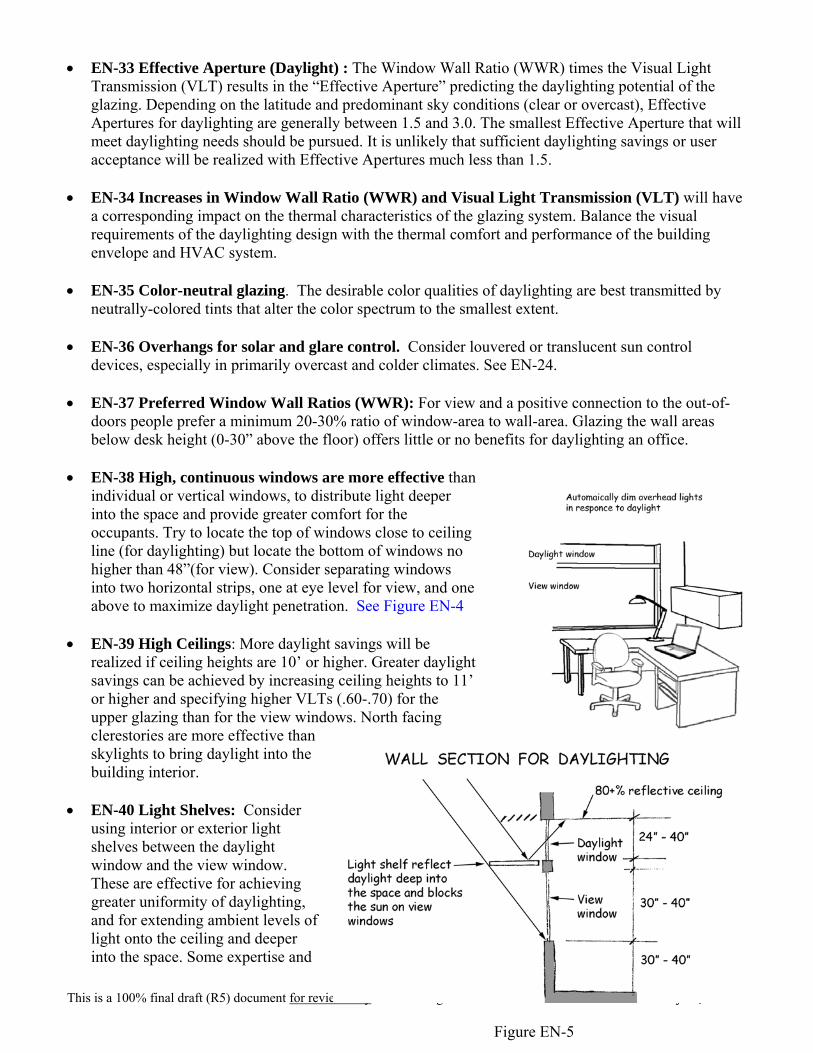
This is a 100% final draft (R5) document for review only and not for general distribution. May 10, 2004
32
• EN-33 Effective Aperture (Daylight) : The Window Wall Ratio (WWR) times the Visual Light Transmission (VLT) results in the “Effective Aperture” predicting the daylighting potential of the glazing. Depending on the latitude and predominant sky conditions (clear or overcast), Effective Apertures for daylighting are generally between 1.5 and 3.0. The smallest Effective Aperture that will meet daylighting needs should be pursued. It is unlikely that sufficient daylighting savings or user acceptance will be realized with Effective Apertures much less than 1.5.
• EN-34 Increases in Window Wall Ratio (WWR) and Visual Light Transmission (VLT) will have
a corresponding impact on the thermal characteristics of the glazing system. Balance the visual requirements of the daylighting design with the thermal comfort and performance of the building envelope and HVAC system.
• EN-35 Color-neutral glazing. The desirable color qualities of daylighting are best transmitted by
neutrally-colored tints that alter the color spectrum to the smallest extent. • EN-36 Overhangs for solar and glare control. Consider louvered or translucent sun control
devices, especially in primarily overcast and colder climates. See EN-24. • EN-37 Preferred Window Wall Ratios (WWR): For view and a positive connection to the out-of-
doors people prefer a minimum 20-30% ratio of window-area to wall-area. Glazing the wall areas below desk height (0-30” above the floor) offers little or no benefits for daylighting an office.
• EN-38 High, continuous windows are more effective than
individual or vertical windows, to distribute light deeper into the space and provide greater comfort for the occupants. Try to locate the top of windows close to ceiling line (for daylighting) but locate the bottom of windows no higher than 48”(for view). Consider separating windows into two horizontal strips, one at eye level for view, and one above to maximize daylight penetration. See Figure EN-4
• EN-39 High Ceilings: More daylight savings will be
realized if ceiling heights are 10’ or higher. Greater daylight savings can be achieved by increasing ceiling heights to 11’ or higher and specifying higher VLTs (.60-.70) for the upper glazing than for the view windows. North facing clerestories are more effective than skylights to bring daylight into the building interior.
• EN-40 Light Shelves: Consider
using interior or exterior light shelves between the daylight window and the view window. These are effective for achieving greater uniformity of daylighting, and for extending ambient levels of light onto the ceiling and deeper into the space. Some expertise and
Figure EN-4
Figure EN-5
This is a 100% final draft (R5) document for review only and not for general distribution. May 10, 2004
33
analysis will be required to design an effective light shelf. See Figure EN-5. • EN-41 Window and Office placement: Daylighting is more cost effective if open plan workstations
are located on the north and south side of the building since open plan areas are more continuously occupied and achieve lower savings from occupancy sensors. The open configuration also absorbs less light, and inter-reflections provide a more uniform distribution of light deep into the space. The control of heat and glare on the east and west facades is difficult, because daylight and views are blocked in an effort to properly control the low sun angles. By placing private offices on the east and west, occupants can individually control their blinds, and thereby control thermal discomfort and glare.
• EN-42 Interior Sun Control: Similar to exterior sun control, horizontal blinds on the south windows
and vertical blinds on the east and west are most effective. In northern latitudes, low angles of sun can enter the north windows on summer mornings and afternoons. Vertical blinds that retract fully for the middle of the day are recommended for these conditions. Perforated blinds and translucent shades may cause glare when hit by direct sunlight.
Cautions (Safeguards):
The Strategy Sets recommended for each climate will only be successful and acceptable to owner and occupants if the design safeguards are met:
• EN-43 VLTs below 0.35 may appear noticeably tinted and dim to occupants, which degrades
luminous quality. Higher VLTs are more effective for daylighting in northern cities and overcast climates.
• EN-44 Tinted or reflective glass. The use of clear low-e or neutrally colored tints, rather than reflective or colored glazing, provides a more user-acceptable daylighted environment.
References (window design): • EPRI Daylight Design: Smart & Simple 1997, available from IESNA at IESNA.org • LBL Daylight and Windows. LBL Tips for Daylighting with Windows available from Lawrence
Berkeley National Laboratories at http://windows.lbl.gov/daylighting/designguide/designguide.html • Daylighting Design by Benjamin Evans, in time Saver Standards for Architectural Design Data,
McGraw-Hill., 1997 B. Lighting
DAYLIGHTING: Good Design Practice (How-To):
• DL-1 Savings and Occupant Acceptance: Daylighting will only save energy if the electric lighting
consumption is reduced, and heat gain and loss through glazing is controlled. In addition, glare and contrast must be controlled so occupants are comfortable and will not override electric lighting controls. See additional comments related to window design and placement.
This is a 100% final draft (R5) document for review only and not for general distribution. May 10, 2004
34
• DL-2 Use of “manual-on” occupancy sensors in daylighted spaces save energy because electricity is not automatically consumed unnecessarily. Use of local articulated task lights (desk lamps that can be adjusted in three planes) in daylit spaces increases occupant satisfaction and is an effective supplement for daylighting. See Figure EN-4.
• DL-3 Reflectances: The use of light-colored materials and matte finishes in all daylighted spaces
increases efficiency through inter-reflections, and greatly increases visual comfort. See EL-3. • DL-4 Lower furniture partitions in open plan office areas increase the efficiency of both the
daylighting and the electric lighting system, by reducing absorption and unwanted shadows. See EN-41 and EL-1.
Cautions (Safeguards): The Recommendations in Section 3 will only be successful and acceptable to owner and occupants if the lighting design safeguards for the quality and quantity of light are met:
• DL- 5 Control of Direct Sun Penetration: • Shield workspaces from direct sun. • Use interior vertical slat blinds to control glare and low angle sun penetration, particularly on east
and wet facing glazing. • For “toplighting”, use north facing clerestories to control direct sun. • For skylights, use light reflecting baffles and/or diffusing glazing to control direct sun
Daylighting utilizes light from the sky, either in its brightest intensity on a clear sunny day or in a diffuse form on a cloudy or hazy day. Patches of direct sunlight in the employees’ view create unacceptable brightness and excessive contrast between light and dark room surfaces. Exterior sun control or overhangs help reduce both glare and heat gain for vertical glazing surfaces.
If light shelves are used with south facing glazing, direct sun should be shielded below the light shelf. The shelf needs to be deep enough to shield windows above the shelf from direct sun. See Figure EN-5.
• DL-6 Orientation of Workstations to Vertical Glazing: • Orient workstations with computer monitors at 90 degrees (+/- 30 degrees) to windows.
It can be visually very stressful to work at a computer monitor while simultaneously viewing bright sunlit scene outside the window. Just as visually exhausting is dealing with the reflection on one’s computer screen from a bright window or skylight. Avoid either of these circumstances by laying out workstations with this in mind.
• DL-7 Skylight Thermal Transmittance:
For Hot Climates:
• Reduce thermal gain during the cooling season by using skylights with a low overall thermal transmittance. This overall U-value includes the glazing only.
• Use north-facing clerestories for skylighting whenever possible in hot climates to eliminate excessive solar heat gain.
This is a 100% final draft (R5) document for review only and not for general distribution. May 10, 2004
35
• Shade skylights on south, east and west oriented sloping roofs with exterior sun control such as screens, baffles, or fins.
• Use smaller aperture skylights in a grid pattern to gain maximum usable daylight with the least thermal heat transfer.
For Moderate and Cooler Climates:
• Reduce summer heat gain as well as winter heat loss by using skylights with a low overall thermal transmittance. The overall U-value includes the glazing. Use a skylight frame that has a thermal break to prevent excessive heat loss/gain and winter moisture condensation on the frame. Insulate the skylight curb above the roof line with continuous rigid insulation.
• Use either north or south facing clerestories for skylighting, but not east or west. E-W glazing adds excessive summer heat gain and makes it difficult to control direct solar gain. Clerestories with operable glazing may also help provide natural ventilation in temperate seasons when air conditioning is not in use.
• Use smaller aperture skylights in a grid pattern to gain maximum usable daylight with the least thermal heat transfer. Do not exceed maximum prescribed glazing area.
• DL-8 Interactions: Thermal gains and losses associated with windows should be balanced with daylighting related savings due to reduction in electric lighting consumption.
References: • EPRI Daylighting Design: Smart and Simple. 1997, available from IESNA at IESNA.org • NBI Advanced Lighting Guidelines, available at newbuildings.org DAYLIGHTING CONTROLS DL-9 Expanded Recommendations for Daylighting Controls: The following recommendations will be
necessary to achieve the 30% energy savings in buildings with 30% Window Wall Ratio or higher. • Dimming Controls: In office work areas, continuously dim rather than switch electric lights in
response to daylight, to minimize employee distraction. Specify dimming ballasts that dim down to at least 10% of full output. Automatic multi-level daylight switching may be used in non-office environments like hallways, storage, restrooms, lounges, lobbies, etc. Locate luminaires in rows parallel to the window wall, and wire each row separately, if located in the daylight zone (within 12’ from the window wall). The daylighting control system and /or photosensor should include a 5-minute time delay or other means to avoid cycling caused by rapidly changing sky conditions, and a one minute fade rate to change the light levels by dimming.
• Correct Photosensor placement is essential: Consult daylighting references or work with
photosensor manufacturer for proper location. • Photosensor specifications: Photosensors used for offices should be specified for the appropriate
illuminance range (indoor or outdoor) and must achieve a slow, smooth linear dimming response from the dimming ballasts. When a daylighting system is designed to evaluate the combined illuminance from daylight and electric light sources (a “closed loop” system), photocells must have filtering or other strategy to achieve and equal response to the color spectrums of the different sources.
This is a 100% final draft (R5) document for review only and not for general distribution. May 10, 2004
36
• Calibration and Commissioning are essential: All lighting controls must be calibrated and
commissioned after the furniture is in place, but prior to occupancy. Include requirements in the specifications.
Good Practice Daylighting Controls(How-To): • DL-10 Photo sensor placement: A “closed loop” system is one where the interior photocell responds
to the combination of daylight and electric light on the primary work surface. The best location for the photocell is above an unobstructed location such as an interoffice circulation path. The photocell is adjusted to achieve the desired light level at a light meter placed on the worst-case desktop. An “open loop” system is one where the photocell responds only to daylight levels but is still calibrated to the desired light level received at a desktop. The best location for the photo sensor is inside the window frame or skylight well.
Cautions Daylighting Controls (Safeguards): The Recommendation in Chapter 4 will only be successful and acceptable to owner and occupants if the lighting design safeguards for the quality and quantity of light are met:
• DL-11 Calibration and Commissioning: Even a few days of occupancy with poorly calibrated
controls can lead to permanent overriding of the system and loss of all savings. Most photosensors require a daytime and nighttime calibration session. The Photosensor manufacturer and the Commissioning Provider should be involved in the calibration.
• DL-12 Daylight Levels: Occupants expect higher combined light levels in daylit spaces.
Consequently, it is more acceptable to occupants when the electric lights are calibrated to dim when the combined daylight and electric light on the worksurface exceeds 1.20 times the designed light level. I.e., if the ambient electric light level is designed for 35 maintained footcandles, the electric lights should begin to dim when the combined level is 42 footcandles. (35 x 1.20= 42). Local task lighting can supplement this level, but should be turned off during the calibration process.
• DL-13 Interactions: Energy savings due to reduced electrical consumption from daylighting should
be weighed against any potential loss caused by increased cooling or heating loads. References: • EPRI Daylighting Design: Smart and Simple, 1997, available from IESNA at IESNA.org • EPRI Lighting Controls – Patterns for Design, 1996, available from IESNA at IESNA.org • NBI Advanced Lighting Guidelines, available at newbuildings.org
ELECTRIC LIGHTING DESIGN INTERIOR LIGHTING
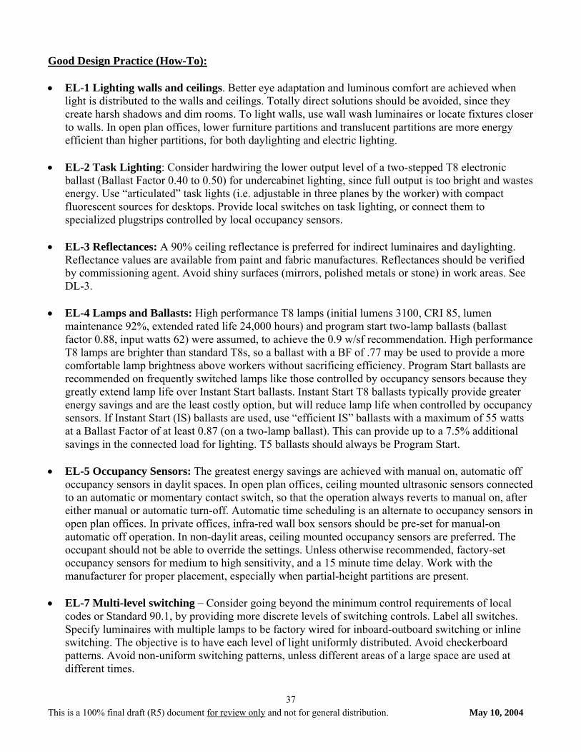
This is a 100% final draft (R5) document for review only and not for general distribution. May 10, 2004
37
Good Design Practice (How-To): • EL-1 Lighting walls and ceilings. Better eye adaptation and luminous comfort are achieved when
light is distributed to the walls and ceilings. Totally direct solutions should be avoided, since they create harsh shadows and dim rooms. To light walls, use wall wash luminaires or locate fixtures closer to walls. In open plan offices, lower furniture partitions and translucent partitions are more energy efficient than higher partitions, for both daylighting and electric lighting.
• EL-2 Task Lighting: Consider hardwiring the lower output level of a two-stepped T8 electronic
ballast (Ballast Factor 0.40 to 0.50) for undercabinet lighting, since full output is too bright and wastes energy. Use “articulated” task lights (i.e. adjustable in three planes by the worker) with compact fluorescent sources for desktops. Provide local switches on task lighting, or connect them to specialized plugstrips controlled by local occupancy sensors.
• EL-3 Reflectances: A 90% ceiling reflectance is preferred for indirect luminaires and daylighting.
Reflectance values are available from paint and fabric manufactures. Reflectances should be verified by commissioning agent. Avoid shiny surfaces (mirrors, polished metals or stone) in work areas. See DL-3.
• EL-4 Lamps and Ballasts: High performance T8 lamps (initial lumens 3100, CRI 85, lumen
maintenance 92%, extended rated life 24,000 hours) and program start two-lamp ballasts (ballast factor 0.88, input watts 62) were assumed, to achieve the 0.9 w/sf recommendation. High performance T8 lamps are brighter than standard T8s, so a ballast with a BF of .77 may be used to provide a more comfortable lamp brightness above workers without sacrificing efficiency. Program Start ballasts are recommended on frequently switched lamps like those controlled by occupancy sensors because they greatly extend lamp life over Instant Start ballasts. Instant Start T8 ballasts typically provide greater energy savings and are the least costly option, but will reduce lamp life when controlled by occupancy sensors. If Instant Start (IS) ballasts are used, use “efficient IS” ballasts with a maximum of 55 watts at a Ballast Factor of at least 0.87 (on a two-lamp ballast). This can provide up to a 7.5% additional savings in the connected load for lighting. T5 ballasts should always be Program Start.
• EL-5 Occupancy Sensors: The greatest energy savings are achieved with manual on, automatic off
occupancy sensors in daylit spaces. In open plan offices, ceiling mounted ultrasonic sensors connected to an automatic or momentary contact switch, so that the operation always reverts to manual on, after either manual or automatic turn-off. Automatic time scheduling is an alternate to occupancy sensors in open plan offices. In private offices, infra-red wall box sensors should be pre-set for manual-on automatic off operation. In non-daylit areas, ceiling mounted occupancy sensors are preferred. The occupant should not be able to override the settings. Unless otherwise recommended, factory-set occupancy sensors for medium to high sensitivity, and a 15 minute time delay. Work with the manufacturer for proper placement, especially when partial-height partitions are present.
• EL-7 Multi-level switching – Consider going beyond the minimum control requirements of local
codes or Standard 90.1, by providing more discrete levels of switching controls. Label all switches. Specify luminaires with multiple lamps to be factory wired for inboard-outboard switching or inline switching. The objective is to have each level of light uniformly distributed. Avoid checkerboard patterns. Avoid non-uniform switching patterns, unless different areas of a large space are used at different times.
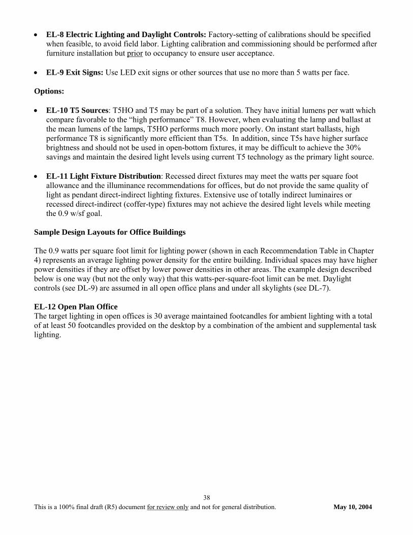
This is a 100% final draft (R5) document for review only and not for general distribution. May 10, 2004
38
• EL-8 Electric Lighting and Daylight Controls: Factory-setting of calibrations should be specified when feasible, to avoid field labor. Lighting calibration and commissioning should be performed after furniture installation but prior to occupancy to ensure user acceptance.
• EL-9 Exit Signs: Use LED exit signs or other sources that use no more than 5 watts per face. Options: • EL-10 T5 Sources: T5HO and T5 may be part of a solution. They have initial lumens per watt which
compare favorable to the “high performance” T8. However, when evaluating the lamp and ballast at the mean lumens of the lamps, T5HO performs much more poorly. On instant start ballasts, high performance T8 is significantly more efficient than T5s. In addition, since T5s have higher surface brightness and should not be used in open-bottom fixtures, it may be difficult to achieve the 30% savings and maintain the desired light levels using current T5 technology as the primary light source.
• EL-11 Light Fixture Distribution: Recessed direct fixtures may meet the watts per square foot
allowance and the illuminance recommendations for offices, but do not provide the same quality of light as pendant direct-indirect lighting fixtures. Extensive use of totally indirect luminaires or recessed direct-indirect (coffer-type) fixtures may not achieve the desired light levels while meeting the 0.9 w/sf goal.
Sample Design Layouts for Office Buildings The 0.9 watts per square foot limit for lighting power (shown in each Recommendation Table in Chapter 4) represents an average lighting power density for the entire building. Individual spaces may have higher power densities if they are offset by lower power densities in other areas. The example design described below is one way (but not the only way) that this watts-per-square-foot limit can be met. Daylight controls (see DL-9) are assumed in all open office plans and under all skylights (see DL-7). EL-12 Open Plan Office The target lighting in open offices is 30 average maintained footcandles for ambient lighting with a total of at least 50 footcandles provided on the desktop by a combination of the ambient and supplemental task lighting.
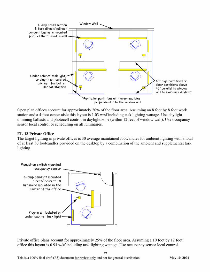
This is a 100% final draft (R5) document for review only and not for general distribution. May 10, 2004
39
Open plan offices account for approximately 20% of the floor area. Assuming an 8 foot by 8 foot work station and a 4 foot center aisle this layout is 1.03 w/sf including task lighting wattage. Use daylight dimming ballasts and photocell control in daylight zone (within 12 feet of window wall). Use occupancy sensor local control or scheduling on all luminaires. EL-13 Private Office The target lighting in private offices is 30 average maintained footcandles for ambient lighting with a total of at least 50 footcandles provided on the desktop by a combination of the ambient and supplemental task lighting.
Private office plans account for approximately 25% of the floor area. Assuming a 10 foot by 12 foot office this layout is 0.94 w/sf including task lighting wattage. Use occupancy sensor local control.
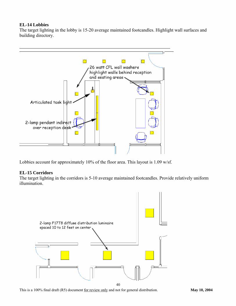
This is a 100% final draft (R5) document for review only and not for general distribution. May 10, 2004
40
EL-14 Lobbies The target lighting in the lobby is 15-20 average maintained footcandles. Highlight wall surfaces and building directory.
Lobbies account for approximately 10% of the floor area. This layout is 1.09 w/sf. EL-15 Corridors The target lighting in the corridors is 5-10 average maintained footcandles. Provide relatively uniform illumination.
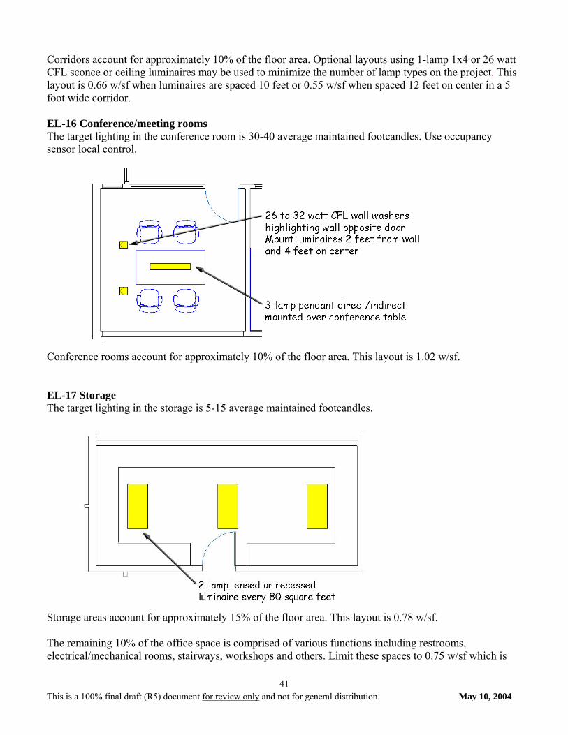
This is a 100% final draft (R5) document for review only and not for general distribution. May 10, 2004
41
Corridors account for approximately 10% of the floor area. Optional layouts using 1-lamp 1x4 or 26 watt CFL sconce or ceiling luminaires may be used to minimize the number of lamp types on the project. This layout is 0.66 w/sf when luminaires are spaced 10 feet or 0.55 w/sf when spaced 12 feet on center in a 5 foot wide corridor. EL-16 Conference/meeting rooms The target lighting in the conference room is 30-40 average maintained footcandles. Use occupancy sensor local control.
Conference rooms account for approximately 10% of the floor area. This layout is 1.02 w/sf. EL-17 Storage The target lighting in the storage is 5-15 average maintained footcandles.
Storage areas account for approximately 15% of the floor area. This layout is 0.78 w/sf. The remaining 10% of the office space is comprised of various functions including restrooms, electrical/mechanical rooms, stairways, workshops and others. Limit these spaces to 0.75 w/sf which is
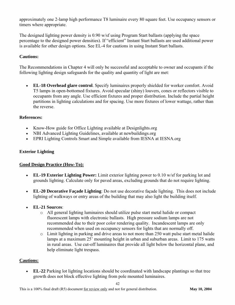
This is a 100% final draft (R5) document for review only and not for general distribution. May 10, 2004
42
approximately one 2-lamp high performance T8 luminaire every 80 square feet. Use occupancy sensors or timers where appropriate. The designed lighting power density is 0.90 w/sf using Program Start ballasts (applying the space percentage to the designed power densities). If “efficient” Instant Start ballasts are used additional power is available for other design options. See EL-4 for cautions in using Instant Start ballasts. Cautions: The Recommendations in Chapter 4 will only be successful and acceptable to owner and occupants if the following lighting design safeguards for the quality and quantity of light are met:
• EL-18 Overhead glare control. Specify luminaires properly shielded for worker comfort. Avoid
T5 lamps in open-bottomed fixtures. Avoid specular (shiny) louvers, cones or reflectors visible to occupants from any angle. Use efficient fixtures and proper distribution. Include the partial height partitions in lighting calculations and for spacing. Use more fixtures of lower wattage, rather than the reverse.
References:
• Know-How guide for Office Lighting available at Designlights.org • NBI Advanced Lighting Guidelines, available at newbuildings.org • EPRI Lighting Controls Smart and Simple available from IESNA at IESNA.org
Exterior Lighting
Good Design Practice (How-To):
• EL-19 Exterior Lighting Power: Limit exterior lighting power to 0.10 w/sf for parking lot and grounds lighting. Calculate only for paved areas, excluding grounds that do not require lighting.
• EL-20 Decorative Façade Lighting: Do not use decorative façade lighting. This does not include lighting of walkways or entry areas of the building that may also light the building itself.
• EL-21 Sources: o All general lighting luminaires should utilize pulse start metal halide or compact
fluorescent lamps with electronic ballasts. High pressure sodium lamps are not recommended due to their poor color rendering quality. Incandescent lamps are only recommended when used on occupancy sensors for lights that are normally off.
o Limit lighting in parking and drive areas to not more than 250 watt pulse start metal halide lamps at a maximum 25’ mounting height in urban and suburban areas. Limit to 175 watts in rural areas. Use cut-off luminaires that provide all light below the horizontal plane, and help eliminate light trespass.
Cautions:
• EL-22 Parking lot lighting locations should be coordinated with landscape plantings so that tree growth does not block effective lighting from pole mounted luminaires.
This is a 100% final draft (R5) document for review only and not for general distribution. May 10, 2004
43
• EL-23 Parking lot lighting should not be significantly brighter than lighting of the adjacent street,
although it should be evenly distributed, have low contrast between the brightest and the least bright area of pavement.
• EL-24 For Parking Lot and Grounds lighting do not increase luminaire wattage in order to use
fewer lights and poles. Increased contrast makes it harder to see at night beyond the immediate fixture location. Flood lights and wall-packs should not be used, as they cause hazardous glare and unwanted light encroachment on neighboring properties.
• EL-25 Use photocell or astronomical time switch on all exterior lighting. If a building energy
management systems is being used to control and monitor mechanical and electrical energy use, it can also be used to schedule and manage outdoor lighting energy use.
• EL-26 For colder climates, CFL luminaires must be specified with cold temperature ballasts and
amalgam lamps. References:
• IESNA Design Guidelines RP-20-1998, RP-33-99, DG-5-94, G-1-03 available from IESNA at IESNA.org
• RPI Outdoor Lighting Pattern Book available at IESNA.org
C. HVAC Good Design Practice (How-To): HV-1 General The HVAC equipment for this Guide includes packaged unit systems and split systems generally referred to as air conditioning units and use warm air heating systems. These systems are suitable for projects with no central plant. This Guide does not cover water source or ground-source heat pumps nor systems that use liquid water chillers or purchased chilled water for cooling nor oil, hot water, solar, steam, or purchased steam for heating. These systems are alternative means that may be used to achieve 30 percent savings over Standard 90.1-1999 and the basic principles of this Guide would apply, but are not part of the scope of this Guide. The systems included in this Guide are available in pre-established increments of capacity and are characterized with an integral refrigeration cycle and heating source. The components are factory designed and assembled into a package that includes fans, motors, filters, heating source, cooling coil, refrigerant compressor, refrigerant-side controls, air-side controls, and an integral or remote condenser. Performance characteristics vary among manufacturers and the selected equipment should match the sensible, latent, and heating loads calculated, including part load performance of the refrigeration system. See HV-3 Cooling and Heating Loads for calculating the loads and HV-13 Thermal Zones for recommendations on zoning the building. See HV-21 Zone Temperature Control for discussion on location of space thermostats. The equipment should be listed to be in conformance with electrical and safety standards and, capacities should be certified by a nationally recognized testing laboratory.
This is a 100% final draft (R5) document for review only and not for general distribution. May 10, 2004
44
The packaged units are generally mounted on the roof, but they may also be mounted at grade level. Split systems generally have the blower unit including filters and coils located indoors or outdoors and the condensing unit outdoors on the roof or at grade level. The equipment should be located that results in minimizing fan power, ducting, and wiring.
Natural gas, propane, electric resistance, and refrigerant gas heating options are available.
HV-2 HVAC System Types This Guide considers packaged unit systems and split systems with refrigerant based Direct Expansion (DX) system for electric cooling and heating by means of one of the three following options: 1. Option 1: Indirect gas-fired heater. 2. Option 2: Electric resistance heat. 3. Option 3: Heat pump unit. Where variable air volume systems are used, the DX coil should be a full-face, intertwined-type coil to prevent bypass of air through sections of the coil without refrigerant flow. The controls of a variable air volume system should be arranged to reduce the supply air to the minimum set point for ventilation before reheating, re-cooling or mixing of air occurs. Variable speed drives should be used to reduce airflow, fan/motor energy, and maintain stable fan and refrigeration operation. Indirect gas-fired heaters use a heat exchanger as part of the factory assembled unit to separate the burner and products of combustion from the circulated air. Electric resistance heaters are part of the factory assembled unit and do not refer to electric resistance heaters installed in the duct distribution system. Heat pump units may use either electric or gas for the auxiliary heat source when the heating load cannot be met by the heat pump alone. The auxiliary heat source will also be used during defrost cycles.
HV-3 Cooling and Heating Loads Heating and cooling system design loads for the purpose of sizing systems and equipment should be calculated in accordance with generally accepted engineering standards and handbooks such as ASHRAE Handbook of Fundamentals. Any safety factor applied should be done cautiously and applied only to building’s internal building loads to prevent over sizing of equipment and short cycling of compressors, which could result in the inability of the system to dehumidify the building properly. Include the cooling and heating load of the outdoor air to determine the total cooling and heating requirements of the unit. On variable air volume systems, the minimum supply airflow to a zone must comply with local code, Standard 62, and Standard 90.1. HV-4 Humidity Control The air conditioning units can use multiple compressors to control refrigeration capacity. For part loads and variable air volume systems, multiple compressors are desirable to reduce the capacity as low as
This is a 100% final draft (R5) document for review only and not for general distribution. May 10, 2004
45
possible to meet the minimum cooling requirements and operate efficiently at part loads. As the sensible load decreases non-proportionately with the latent load, the space relative humidity can increase at part load. Examine the system performance at part load to ensure that the space relative humidity remains below 60 percent when the sensible load is at 50 percent of peak design. On systems with multiple compressors, the compressors turn on or off or unload to maintain the space air temperature setpoint. The temperature of the air leaving the unit can be reset upward when compressor capacity reduction is not possible, however, this strategy must consider the need to maintain relative humidity within the space below 60 percent. HV-5 ENERGY RECOVERY
An energy recovery ventilator, unitary accessory, or integrated component should be selected to provide the outdoor air requirements on systems greater than 5000 CFM and when the quantity of outdoor air exceeds 70 percent of the supply air. The energy recovery unit should meet or exceed the RER (Recovery Energy Ratio) shown in the Climate Recommendation Tables in Section 4. For maximum benefit, energy recovery designs should provide as close to balanced intake and exhaust airflows as is practical, taking in account the need for building pressurization and any exhaust that cannot be incorporated into the system. Exhaust for the energy recovery unit may be taken from spaces requiring exhaust (using a central exhaust duct system for each unit) or directly from the return airstream (as with a unitary accessory or integrated unit). Where economizers are recommended, the energy recovery system should be controlled in conjunction with the economizer and may be able to provide an economizer function. In cold climates, manufacturer’s recommendations for frost control should be followed.
HV-6 Equipment Efficiency The efficiency of the cooling and heating equipment is shown in the Climate Recommendation Tables in Section 4. The heating and cooling components are generally assembled together in one unit and the recommended minimum efficiency of one component may have to be exceeded in order to meet the minimum efficiency of the other. The cooling equipment should meet or exceed the listed SEER (Seasonal Energy Efficiency Ratio) or EER (Energy Efficiency Ratio) for the required capacity. The cooling equipment should also meet or exceed the IPLV (Integrated Part Load Value) listed. Heating equipment should meet or exceed the listed AFUE (Annual Fuel Utilization Efficiency) or Thermal Efficiency for indirect gas-fired equipment at the required capacity. For heat pump applications, the heating duty should meet or exceed the listed HSPF (Heating Seasonal Performance Factor) or COP (Coefficient of Performance) for the required capacity based on 47 degrees F outdoor air temperature.
HV-7 Ventilation Air The amount of ventilation air should be based on ANSI/ASHRAE Standard 62-2001. The number of people should be based on either the known occupancy, local code, or Standard 62.
This is a 100% final draft (R5) document for review only and not for general distribution. May 10, 2004
46
Each air conditioning unit should have an outdoor air connection through which ventilation air is introduced and mixes with the return air. The outdoor air can be mixed with the return air either in the ductwork prior to the air conditioning unit or at the unit’s mixing plenum. In either case, the damper and duct/plenum should be arranged to promote mixing and minimize stratification. An air economizer mode can save energy by using outdoor air for cooling in lieu of mechanical cooling when the temperature of the outdoor air is low enough to meet the cooling needs. The system should be capable of modulating the outdoor air, return air, and relief air dampers to provide up to 100-percent of the design supply air quantity as outdoor air for cooling. Climate Zones 1 through 3 should use a motorized damper over a gravity damper for units below 65,000 Btuh in order to prevent outdoor air from entering during the unoccupied periods when the unit may recirculate air to maintain setback or setup temperatures. The motorized outdoor air damper for all climate zones should be closed during the full unoccupied period. Demand control ventilation should be used in areas that have varying and high occupancy loads during the occupied periods to vary the amount of outdoor air in response to the need in a zone. The amount of outdoor air should be controlled by Carbon Dioxide sensors that measure the change in carbon dioxide levels in a zone relative to the levels in the outdoor air. A controller that will determine which zone has the greatest carbon dioxide change will operate the outdoor air, return air, and relief air dampers to maintain proper ventilation. See HV-14 Control Strategies for methods of operating the system efficiently. HV-8 EXHAUST AIR
Separate exhaust systems for toilet rooms, janitor closets, etc., should be interlocked to operate with the air conditioning unit except during unoccupied periods. The exhaust system should have a motorized damper that opens and closes with the operation of the fan. The damper should be located as close to the duct penetration of the building envelope to minimize conductive heat transfer through the duct wall. During unoccupied periods, the damper should remain closed even while the air conditioning unit is operating to maintain setback or setup temperatures.
HV-9 Ductwork Distribution Air should be ducted through low pressure (System Pressure Classification of less than 2-inches), rigid ductwork. Supply and return air should be ducted to supply diffusers and return registers in each individual space. The ductwork should be direct as possible, minimizing the number of elbows, abrupt contractions and expansions, and transitions. Long radius elbows and 45 degree lateral take-offs should be used wherever possible. Where variable air volume systems are used, they should have single duct air terminal units to control the volume of air to the zone based on the space temperature sensor. In general, the following sizing criteria should be used for the duct system components: 1. Diffusers and registers should be sized at 0.05-inch static pressure drop. 2. Supply and return ductwork should be sized at 0.05-inch per 100 linear feet of duct run.
This is a 100% final draft (R5) document for review only and not for general distribution. May 10, 2004
47
Flexible ductwork should be the insulated type and should be: 1. Limited to 5 feet or less, 2. Installed without any kinks, and 3. Installed with a durable elbow support when used as an elbow. Ductwork should not be installed outside the building envelope in order to minimize heat gain to, or heat loss from, the ductwork due to outdoor air temperatures and solar heat gain. Ductwork should enter or leave the air conditioning unit through an insulated roof curb around the perimeter of the air conditioning unit’s footprint. Duct static pressures should be designed and, equipment and diffuser selections should be selected to not exceed the noise criteria for the space. See HV-19 Noise Control for additional information.
HV-10 Duct Insulation All supply air ductwork should be insulated. Exception: In non-ceiling spaces, only the duct mains and major branches should be insulated. Individual branches and runouts to diffusers in the space being served need not be insulated. All return air ductwork located above the ceiling immediately below the roof should be insulated. All outdoor air ductwork should be insulated. All exhaust and relief air ductwork between the motor operated damper and penetration of the building exterior should be insulated. Include a vapor retardant on the outside of the insulation where condensation is possible. The R-value of the insulation should meet or exceed the values listed in the Climate Recommendation Tables in Section 4. HV-11 Duct Sealing and Leakage The ductwork should be sealed for Seal Class B and leak tested at the rated pressure. The leakage should not exceed the allowable CFM/100 square foot of duct area for the seal and leakage class of the system’s air quantity apportioned to each section tested. See HV-21 Testing, Adjusting, and Balancing for guidance on insuring system performance.
HV-12 Fan Motors Motors for fans should be high efficiency motors.
HV-13 Thermal Zones Office buildings should be divided into thermal zones based on building size, part-load performance requirements, space layout and function, number of tenants, and the needs of the user. One zone for each of the perimeter exposures, one for the top floor, one for the bottom floor, and one for the interior would be ideal. However, for small buildings this may be impractical or unnecessary as in the case of a large open office layout. Zoning can also be accomplished using multiple air handling units or by having multiple zone control with a single air handling unit. The temperature sensor for a zone should be located in a room representative of that entire zone.
This is a 100% final draft (R5) document for review only and not for general distribution. May 10, 2004
48
HV-14 CONTROL STRATEGIES
The use of control strategies can help to reduce energy. Time of day scheduling is useful when it is known which portions of the building will have reduced occupancy. Control of the ventilation air system can be tied into this control strategy. Having a setback temperature for unoccupied periods during the heating season or setup temperature during the cooling season will help to save the energy required to heat up or cool down large masses within the building. A pre-occupancy operation period before occupancy will help to purge the building of contaminants that build-up overnight from the outgassing of products. HV-15 TESTING, ADJUSTING, AND BALANCING
After the system has been installed, cleaned, and is placed in continuous operation, the system should be tested, adjusted, and balanced for proper operation. This procedure will help to ensure that the correct sized diffusers, registers, and grilles have been installed, each space receives the required airflow, the equipment meets the intended performance, and the controls operate as intended. The instruments used in the measurement should be certified that they have been calibrated within 12 months prior to use. A written report should be submitted for inclusion in the Operation and Maintenance Manuals. Cautions: HV-16 HEATING SOURCES
Electric resistance heaters and gas heaters require a minimum airflow rate to operate. The air conditioning unit should include factory-installed safeties to shut down heater when there is low or no airflow. HV-17 FILTERS
Air conditioning unit filters are included as part of the factory assembled unit and will be selected by the equipment manufacturer, dependent on the airflow. Replacement of dirty filters should correspond to the manufacturer’s recommendations. Use filter pressure drop monitors to send an alarm when the filter pressure-drop exceeds the manufacturer’s recommendation. HV-18 RETURN AIR FAN
A separate return air fan should be used whenever the duct static pressure loss in the return air ductwork exceeds 0.5-inches of water. HV-19 NOISE CONTROL
Acoustical requirements may necessitate attenuation of the supply and/or return air. Avoid short, direct runs of ductwork between the fan and supply or return outlet. Avoid installation of the air conditioning units above occupied spaces. Consider locations above less critical spaces such as storage areas, toilet rooms, corridors, etc.
HV-20 HEATING SUPPLY AIR TEMPERATURES
The heating supply air temperature of heat pump units is generally 90 to 100 degrees F. The discharge air temperature from heating coils should be limited to 100 degrees F when and where possible to promote good mixing within the room and prevent stratification. Ducts and supply registers should be selected to control air velocity and throw in order to minimize the perception of cool drafts.
This is a 100% final draft (R5) document for review only and not for general distribution. May 10, 2004
49
HV-21 ZONE TEMPERATURE CONTROL
The number of spaces on a zone, and the location of the temperature sensing point, will affect the control of temperature in the various spaces of a zone. A single temperature sensing point in the return air duct for a zone with multiple spaces provides an average temperature reading. Some spaces may be overcooled and some may be overheated. Locating the temperature sensor in one room of a zone with multiple spaces only provides feedback based on the conditions of that room. Locating a single temperature sensor in a large open area may provide a better response to the conditions of the zone with multiple spaces. Selecting the room or space that will best represent the thermal characteristics of the space due to both external and internal loads will provide the greatest comfort level. The final selection should be based on building orientation, space layout, and function. HV-22 CARBON DIOXIDE SENSORS
The number and location of carbon dioxide sensor for demand control ventilation can affect the accuracy of the reading and may not reflect the actual levels in a zone. The number and location of sensors should be based on the manufacturer’s recommendations. References: ASHRAE - Applications Handbook
ASHRAE - Fundamentals Handbook ASHRAE - Systems and Equipment Handbook D. SERVICE WATER HEATING Good Design Practice (How-To):
WH-1 Service Water Heating Types The service water heating equipment for this Guide considers the type of fuel source used for the HVAC heating system. This Guide does not cover systems that use oil, hot water, solar, heat pump, steam, or purchased steam for generating service water heating. These systems are alternative means that may be used to achieve 30 percent savings over Standard 90.1-1999 and the basic principles of this Guide would apply, but are not part of the scope of this Guide. The service water heating equipment included in this Guide for the corresponding three HVAC options are: 1. HVAC Options 1 and 3: Gas-fired water heater. 2. HVAC Options 2 and 3: Electric-resistance water heater. The factory assembled components of a service water heater generally include thermostat(s), temperature and pressure relief valve, and controls for all types of water heaters; insulated tank for storage units; electric heating elements for electric units; gas burner for all gas units; electric ignition for atmospheric gas units; and forced draft blower for gas powered units.
This is a 100% final draft (R5) document for review only and not for general distribution. May 10, 2004
50
Natural gas and propane fuel sources are available options for gas-fired units.
WH-2 System Description 1. Gas-Fired Instantaneous Water Heater: Atmospheric-type, water heater with minimal water
storage capacity. Control is generally by means of a flow switch that controls the burner, and may have a modulating fuel valve that varies fuel flow as water flow changes. The device also includes a vent for exhausting the products of combustion.
2. Gas-Fired Storage Water Heater: Forced-draft type, water heater with a power burner and a
vertical or horizontal tank. A thermostat controls the amount of gas to the heater’s burner. Includes a vent to exhaust the products of combustion and a direct intake for combustion air.
3. Electric Resistance Instantaneous Water Heater: Compact, wall mounted type, consisting of an
insulated enclosure. A thermostat controls the heating element which may be of the immersion or surface-mounted type.
WH-3 Sizing The average service water-heating load for an office building is 1.0 gallon/person/day. The supply water temperature should be 120 degrees F to avoid injuries due to scalding. Systems with storage capacity should generate 140 degrees F water to limit the potential for Legionella growth and include an anti-scald type mixing valve to deliver 120 degrees water to the fixture outlet.
WH-4 Equipment Efficiency
The efficiency of gas-fired water heaters should meet or exceed the values in the Climate Recommendation Tables in Section 3 High efficiency, condensing boilers are an optional alternative to the boiler efficiencies listed that will most likely result in savings that exceed the 30 percent target of this Guide. The materials of construction should be selected to be compatible with the acidic nature of the condensate. Disposal of the condensate should be done in a manner acceptable. The tank for storage type water heaters should be standard manufacturers’ sizes for the capacity selected. WH-5 LOCATION
The water heater should be located close to the hot water fixtures to avoid the use of a hot water return loop or the use of heat tracing on the hot water supply pipe. Point of use water heaters may be considered when the number of fixtures are few or the location of hot water fixtures are scattered throughout the building.
WH-6 Pipe Insulation
This is a 100% final draft (R5) document for review only and not for general distribution. May 10, 2004
51
All service water heating piping should be insulated and installed in accordance with industry accepted standards. Insulation should be protected from damage. Include a vapor retardant on the outside of the insulation. The R-value of the insulation should meet or exceed the listed values in the Climate Recommendation Tables in Section 4. Cautions: WH-7 Showers If an Office Building includes showers, the capacity of the service water heating system should be increased based on the number of showers. WH-8 LEGIONELLA CONTROL
It has been determined that Legionella bacteria can colonize in hot water maintained at 115 degrees F or lower. However, there has also been much written about the potential for Legionella bacteria growth in service water systems maintained below 140 degrees F. Storage systems have a higher potential for this growth. Therefore, it is recommended that storage systems generate 140 degrees F water. References: ASHRAE – Applications Handbook
E. PLUG LOADS PL-1 Additional Energy Savings from Efficient Appliances and Office Equipment Building owners and other users of this Guide can benefit from additional energy savings by outfitting offices with efficient appliances, office equipment, and other devices plugged into electric outlets. These “plug loads” can account for up to 25 percent of a small office building’s annual energy requirements and energy expense. In addition to their own energy requirements, plug loads also are a source of internal heat gains that increase heating and air-conditioning energy use. In office settings, personal computer networks are ubiquitous even in small office operations. Many facilities have significant numbers of personal computers, laptop computers, monitors, printers and network servers. In addition, many offices are equipped with fax machines, copiers and other electronic office gear. Offices may often have employee kitchens with refrigerators, microwave ovens and coffee makers. Some will also have vending machines for cold soft drinks and snacks. Much of this equipment can operate or be on standby 24 hours per day year round. The following recommendations for purchase and operation of plug load equipment (Table PL) are an integral part of this Guide, but the energy savings from the plug load recommendations are expected to be in addition to the target 30% savings. PL-2 They cost you more than you think. Fortunately, there are cost-effective solutions for small office building owners and the design-build contractors who serve them. Plug load equipment that operates at high efficiency with minimal standby energy use is available from numerous manufacturers. Many makes
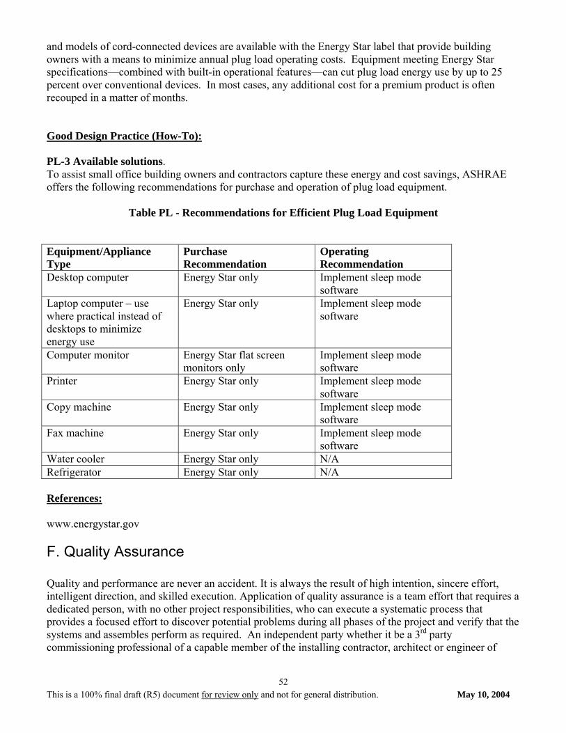
This is a 100% final draft (R5) document for review only and not for general distribution. May 10, 2004
52
and models of cord-connected devices are available with the Energy Star label that provide building owners with a means to minimize annual plug load operating costs. Equipment meeting Energy Star specifications—combined with built-in operational features—can cut plug load energy use by up to 25 percent over conventional devices. In most cases, any additional cost for a premium product is often recouped in a matter of months. Good Design Practice (How-To): PL-3 Available solutions. To assist small office building owners and contractors capture these energy and cost savings, ASHRAE offers the following recommendations for purchase and operation of plug load equipment.
Table PL - Recommendations for Efficient Plug Load Equipment
Equipment/Appliance Type
Purchase Recommendation
Operating Recommendation
Desktop computer Energy Star only Implement sleep mode software
Laptop computer – use where practical instead of desktops to minimize energy use
Energy Star only Implement sleep mode software
Computer monitor Energy Star flat screen monitors only
Implement sleep mode software
Printer Energy Star only Implement sleep mode software
Copy machine Energy Star only Implement sleep mode software
Fax machine Energy Star only Implement sleep mode software
Water cooler Energy Star only N/A Refrigerator Energy Star only N/A References: www.energystar.gov F. Quality Assurance Quality and performance are never an accident. It is always the result of high intention, sincere effort, intelligent direction, and skilled execution. Application of quality assurance is a team effort that requires a dedicated person, with no other project responsibilities, who can execute a systematic process that provides a focused effort to discover potential problems during all phases of the project and verify that the systems and assembles perform as required. An independent party whether it be a 3rd party commissioning professional of a capable member of the installing contractor, architect or engineer of
This is a 100% final draft (R5) document for review only and not for general distribution. May 10, 2004
53
record organization is needed to ensure that the strategy sets and recommendations contained in this guide meet the owners stated requirements. There are exceptions but in general most designers are not comfortable operating and testing assemblies and equipment and most contractors do not have the technical background necessary to evaluate performance. Quality assurance (QA)/Commissioning (Cx) requires an individual with in-depth technical knowledge of the building envelop, mechanical, electrical, and plumbing system and operational and construction experience. The person providing QA/Cx must be able to be objective and respectful of the design and construction team members, but accretive in their responsibility to the owner. Political issues often prevent a member of the design or construction organizations from fulfilling this responsibility. Good Design Practice (How-To): CM-1 Select Team. Selection of the correct team members is critical to the success of a project. Owners who understand the importance of a building’s performance and the impact building performance has on the environment, psychological and physiological perceptions, and the total cost of ownership, also understand the importance of team dynamics in selection of team member responsible for delivering their project. Owners should evaluate qualifications of candidates, past performance, cost of services, and availability of the candidates in making a selection. CM-2 Selection of Quality Assurance Provider Quality Assurance is systematic process of verifying the owner’s project requirements, operational needs, basis of design, and assuring that the building performs in accordance with these defined needs. The selection of a provider should include the same evaluation process the owner would use to select other team members. Qualifications in providing quality assurance services, past performance of projects, cost of services, and availability of the candidate are some of the parameters an owner should investigate and consider in making a selection. CM-3 Owner’s Project Requirements Owner’s Project Requirements (OPR) is a written document that details the functional requirements of a project and the expectations of how the facility will be used and operated. This includes strategies and recommendation selected from this guide (See Table 2-1, and Sections 3 and 4) that will be incorporated into the project, anticipated hours of operation provided by the owner, and basis of design assumption made. The OPR forms the foundation of what the team is tasked with accomplishing by defining project and design goals, measurable performance criteria, Owner directives, budgets, schedules, and supporting information into a single concise document. Quality assurance process depends on a clear, concise, and comprehensive Owner’s Project Requirements document. Development of the OPR document requires input from all key facility users and operators and evolves through each project phase. Documenting decisions made during the Design, Construction, and Occupancy and Operations Phases. It is the primary tool for benchmarking success and quality at all phases of the project delivery and throughout the life of the facility. Included in the OPR are the designers’ assumptions which form the Basis of Design. The Basis of Design records the concepts, calculations, decisions, and product selections used to meet the OPR and to satisfy applicable regulatory requirements, standards, and guidelines. Note: The Owners Project Requirements (OPR) remains relatively fixed from their initial development until directed otherwise by the Owner.
This is a 100% final draft (R5) document for review only and not for general distribution. May 10, 2004
54
CM-4 Budgets Contained in OPR. The OPR provides a description of what the team is tasked with accomplishing and can be used to define the team’s scope in both broad and specific terms. Review of design, construction, and quality assurance scope and budgets is essential. Effort and cost associated with designing and constructing an energy efficient building can and often is lost because performance of the systems are not verified. Owners are best served when scope of quality assurance activities include verification of systems and assemblies that affect performance. CM-5 Design and Construction Schedule. Planning activities is an important part of delivering a project including scheduling of quality assurance activities. Placing quality assurance activities into the design and construction schedule helps with communication of activities required to deliver a building that will perform as anticipated. Identifying both the activity and time required in the schedule for design review and performance verification activities clearly communicates when coordination is required and who should participate. This minimizes time and effort needed to accomplish the activities and allows time for corrective action if needed. All of which results in lowering the owners total cost of ownership. CM-6 Design Review: Verification of the design through a review process by a different party other than the actual designer provides a 2nd pair of eyes with a fresh perspective. This fresh perspective allows identification of issues and opportunities that improves the quality of the documents developed by the team, and verification that the owner’s project requirements from a design perspective are being met. Issues identified can easily be corrected before effort and materials are expended providing potential savings in construction costs and reducing risk to the team (See suggested quality assurance scope for more detail). CM-7 Defining Quality Assurance at Pre-Bid: The building industry has traditionally delivered buildings without using a verification process, typically know as commissioning. As with previous changes in design and construction procedures and practices teams struggle with understanding how the change will affect the various trades biding the project. It is extremely important that the quality assurance/commissioning process be reviewed with the biding contractors to facilitate understanding of what will be expected and how selected parties will work together to deliver an energy efficient building. Reviewing the procedures and describing the activities and interaction helps minimize fear associated with new practices and reduces cost. Teams who have participated in the commissioning process typically appreciate the commissioning process because they are able to resolve problems while their manpower and materials are still on the project. Significantly reducing call backs and warrant costs and enhancing their delivery capacity. Owners benefit from lower total cost of ownership. CM-8 Verifying Building Envelop Construction: The building envelop is a key element of an energy efficient design. Compromises in assembly performance are common and are caused by a variety of factors that can easily be avoided through the quality assurance/commissioning process. Improper placement of insulation, improper or lack of sealing air barriers, wrong or poor performing glazing and fenestration systems, incorrect placement of shading devices, and misplacement of daylighting shelves can significantly compromise the energy performance of the building (See cautions in this section). The perceived value of the commissioning process is that it is an extension of the quality control processes of the designer and contractor as the team works together to produce quality energy efficient projects. Designers and contractors focused on delivering a project are not typically focus on verifying system performance. In order to ensure performance verification is needed. CM-9 Verifying Electrical and HVAC Systems Construction: The performance of the electrical and HVAC systems are key elements of an energy efficient design. Compromises in performance are common resulting in significant increases in energy consumption. Typical problems include incorrect grounding,
This is a 100% final draft (R5) document for review only and not for general distribution. May 10, 2004
55
lighting and HVAC control malfunction, simultaneous heating and cooling, improper refrigerant pipe sizing, restrictions in air distribution, and leaky ductwork. The commissioning process can minimize poor performance through observation and verification process to help ensure that problems are identified and corrected during construction when there are the easiest to correct. CM-10 Performance Testing: Performance testing of systems is essential to ensuring that a project following this guideline will actually attain the energy savings that can be expected from the strategies and recommendations contained in this guide. The quality assurance provider is responsible for developing installation checklists the contractors will use during installation as a quality assurance tool. If the contractors utilize the checklists as intended functional testing of systems will occur quickly and only minor but important issues will need to be resolved to ensure that the building will perform as intended. The quality assurance provider is also responsible for development of functional testing procedures that verify systems perform as intended and witnessing these tests to verify performance. Owner’s with operational and maintenance personnel can use the functional testing process as a training tool to educate their staff on how the systems operate as well as system orientation prior to training. CM-11 Substantial Completion: Substantial generally is associated with completion and acceptance of the life safety systems. Contractors, generally, have not completed the systems sufficiently at substantial completion to verify their performance. There is no shame in a contractor acknowledging that while the systems may be operational they may and probably are not yet operating as intended. Expected performance can only be accomplished when all systems operate interactively to provide the desired results. As contractors finish their scope of work they will identify and resolve many but not all performance problems. The Quality assurance provider helps to take the remaining issue often expressed by the individual contactors and assist with resolution by elevating them up to the team who works to resolve the identified problem. CM-12 Maintenance Manual Submitted and Accepted: Communication of activities the owner will be responsible for completing in order to maintain the manufacturers’ warranties is part of the QA/Cx process. Review of operation and maintenance information for completeness is part of the QA/Cx process to ensure that the owners has the required information needed to establish preventive maintenance programs, facilitate repairs, and operate the facility efficiently. A copy of the OPR should be included to provide the O & M staff with and understanding of how the building is intended to operate and the assumptions the designers made. CM-13 Resolve Quality Control Issues identified throughout the Construction Phase: Issues identified during the construction process are documented into an issues log and raised to the team for collaborative resolution. Issues are tracked and reviewed at progress meetings until the issue is resolved. Completion and acceptance of the systems and assemblies by the owner will be contingent upon what issues are still outstanding at the end of the project. Minor issues may be tracked by the owners O & M staff while other will require resolution before acceptance of the work. The completion of the QA/Cx process is verification that the issues identified have been resolved. CM-14 Final Acceptance: Final acceptance generally occurs after the QA/Cx issues log has been resolved except for minor issues the owner is comfortable with resolving in the warranty period. CM-15 Establish Building Maintenance Program: Continued performance and control of operational and maintenance costs require a maintenance program. The operation and maintenance manuals provide contain information that the O & M staff use to develop this program. The level of expertise typically associate with O & M staff for buildings covered by this guide are generally much lower that larger more complex buildings and typically need assistance with development of a preventative maintenance
This is a 100% final draft (R5) document for review only and not for general distribution. May 10, 2004
56
program. The QA/Cx provider can help bridge the knowledge gaps of the O & M staff and assist the owner with developing a program that would help ensure continued performance. The benefits associated with energy efficient buildings are realized when systems perform as intended and proper maintenance and operation is essential. CM-16 Monitor Post-Occupancy Performance: Establishing measurement and verification procedures that establish a benchmark of performance based on actual building performance after it has been commissioned can identify when corrective action and/or repair are required to maintain energy performance. Utility consumption and factors effecting utility consumption should be monitored and recorded to establish the building performance during the 1st year of operation. The result will be a performance benchmark that will serve as the basis to determine if the building is performing within operational tolerances for the life of the building. Variations in utility usage can be justified based on changes in conditions typically affecting energy use such as weather, occupancy, operational schedule, maintenance procedures, and equipment operations required by these conditions. While most building covered in this guide will not use a formal measurement and verification process tracking the specific parameters listed above does allow the owner to quickly review utility bills and changes in conditions. Poor performance is generally oblivious to the reviewer when comparing the various parameters. QA/Cx providers can typically assist an owner understand when operational tolerances are exceeded and can provide assistance in defining what actions may be required to return the building to peak performance. Suggested Commissioning Scope:
• Review the design team’s documentation (Owner’s Project Requirements) that details the functional requirements of a project and the expectations of how it will be used and operated and identify any areas requiring clarification. The information provided by the design team for review should include project and design goals, measurable performance criteria, budgets, schedules, success criteria, and supporting information.
• Conduct one design review of the 100% complete construction documents providing a verification
that the strategy sets and recommendations adopted by the project team and documented in the OPR are contained and clearly represent in the contract documents. Develop a report identifying identifies concerns and opportunities, documentation of issues. Use the report to tracks issues to resolution, and provides a collaborative process among the Owner, designers, and QA/Cx provider to improve the deliver process and help ensure building performance. The report will track designer responses, document decisions, and provide a method by which direction can be provided to the designers by the owner.
• Conduct one 2-hour meeting to discuss review comments and adjudicate issues with the design team and issue a final report illustrating the disposition of each issue raised. Use the report to verify during construction site visits that issues were corrected.
• Develop project specific quality assurance/commissioning specifications for building envelop, electrical, mechanical, and plumbing systems that will be verified during the delivery of the project. The specifications will incorporate QA/Cx activities into the construction process and provide a clear understanding to all participants their specific roles, responsibilities, and effort. The guide specifications will be reviewed, modified, and blended into the CDs by the designers.
This is a 100% final draft (R5) document for review only and not for general distribution. May 10, 2004
57
• Participate in one 1-hour pre-bid meeting to present the QA/Cx to the bidding contractors and answer questions.
• Prepare Prefunctional checklists and QA/Cx plan and conduct one 1-hour meeting with the project team reviewing QA procedures, roles and responsibilities, and establishing a tentative schedule of QA/Cx activities. During the meeting provide the prefunctional checklists to the contractors for their use during the delivery process.
• Review submittal information for systems being commissioned and provide appropriate comments to team. Based on the submittal information develop functional test procedure that will be used to verify system performance and distribute to team.
• Conduct two site visits during construction to observe construction techniques and to identify issues that may affect performance. Review issues with appropriate team members at end of site visit in accordance to established communication protocols and issue one report per visit documenting findings. Establish and maintain an issues log for tracking issues identified.
• Direct and witness functional testing and document results. Issues identified will be documented in the issues log and tracked to resolution. General contractor will schedule functional testing activities and ensure that responsible parties needed for verification are present.
• Review operation and maintenance information to ensure warranty requirements and preventative maintenance information required is part of the documentation along with a copy of the owner’s project requirements and basis of design information.
• Witness training of O&M staff to help ensure O&M staff understand systems, their operation, warranty responsibilities, and preventative maintenance requirements.
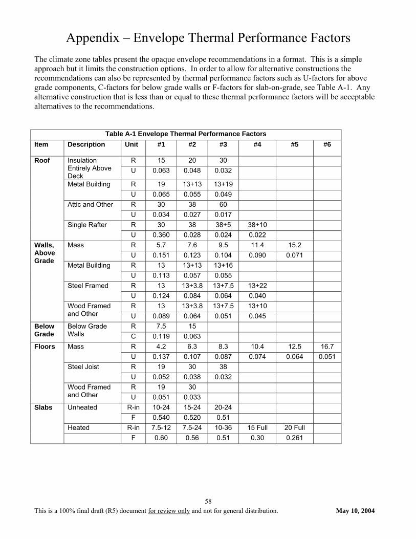
This is a 100% final draft (R5) document for review only and not for general distribution. May 10, 2004
58
Appendix – Envelope Thermal Performance Factors The climate zone tables present the opaque envelope recommendations in a format. This is a simple approach but it limits the construction options. In order to allow for alternative constructions the recommendations can also be represented by thermal performance factors such as U-factors for above grade components, C-factors for below grade walls or F-factors for slab-on-grade, see Table A-1. Any alternative construction that is less than or equal to these thermal performance factors will be acceptable alternatives to the recommendations.
Table A-1 Envelope Thermal Performance Factors Item Description Unit #1 #2 #3 #4 #5
#6
R 15 20 30 Insulation Entirely Above Deck
U 0.063 0.048 0.032
R 19 13+13 13+19 Metal Building U 0.065 0.055 0.049 R 30 38 60 Attic and Other U 0.034 0.027 0.017 R 30 38 38+5 38+10
Roof
Single Rafter U 0.360 0.028 0.024 0.022 R 5.7 7.6 9.5 11.4 15.2 Mass U 0.151 0.123 0.104 0.090 0.071 R 13 13+13 13+16 Metal Building U 0.113 0.057 0.055 R 13 13+3.8 13+7.5 13+22 Steel Framed U 0.124 0.084 0.064 0.040 R 13 13+3.8 13+7.5 13+10
Walls, Above Grade
Wood Framed and Other U 0.089 0.064 0.051 0.045
R 7.5 15 Below Grade
Below Grade Walls C 0.119 0.063
R 4.2 6.3 8.3 10.4 12.5 16.7 Mass U 0.137 0.107 0.087 0.074 0.064 0.051 R 19 30 38 Steel Joist U 0.052 0.038 0.032 R 19 30
Floors
Wood Framed and Other U 0.051 0.033
R-in 10-24 15-24 20-24 Unheated F 0.540 0.520 0.51
Heated R-in 7.5-12 7.5-24 10-36 15 Full 20 Full
Slabs
F 0.60 0.56 0.51 0.30 0.261