Embed Size (px)
Citation preview
Operating ManualOriginal Instructions
D446306XAvers. 2.0
040 044 045 046SPEED
B
C
D
B
C
D
B
C
D
B
C
D
A
B
C
A
B
CB
C
D
B
C
D
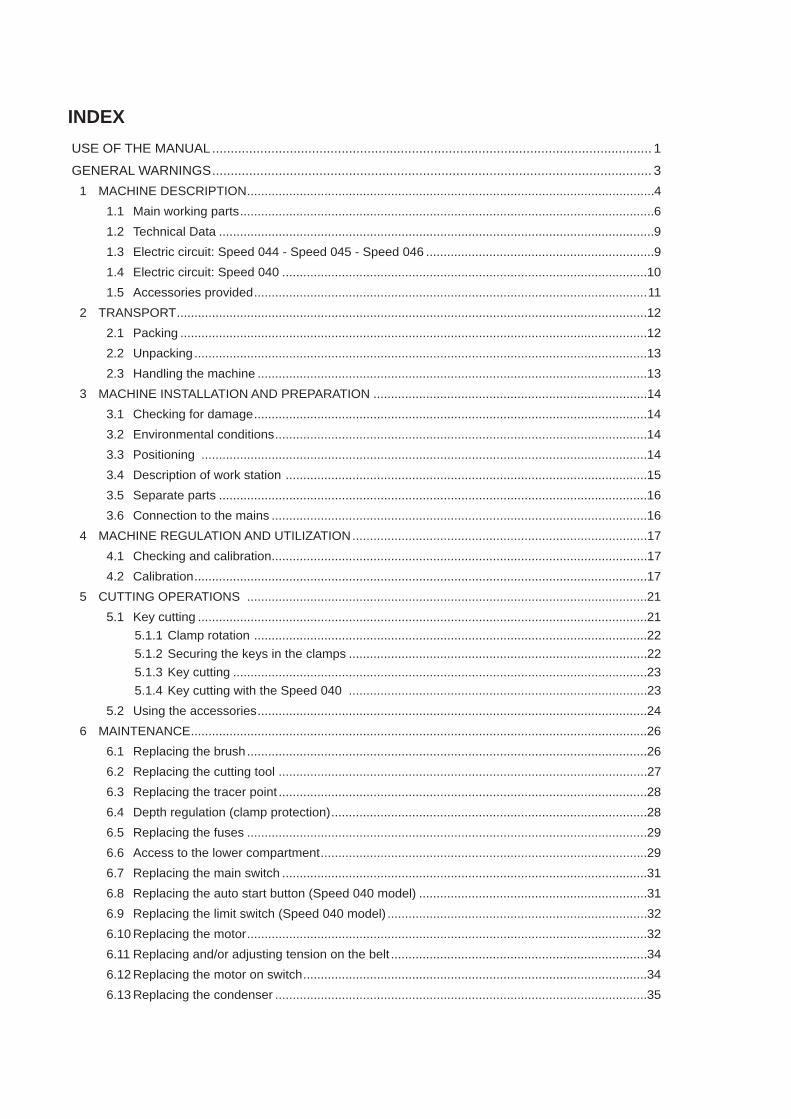
INDEXUSE OF THE MANUAL ....................................................................................................................... 1
GENERAL WARNINGS ....................................................................................................................... 31 MACHINE DESCRIPTION ....................................................................................................................4
1.1 Main working parts ......................................................................................................................61.2 Technical Data ............................................................................................................................91.3 Electric circuit: Speed 044 - Speed 045 - Speed 046 .................................................................91.4 Electric circuit: Speed 040 ........................................................................................................101.5 Accessories provided ................................................................................................................11
2 TRANSPORT ......................................................................................................................................122.1 Packing .....................................................................................................................................122.2 Unpacking .................................................................................................................................132.3 Handling the machine ...............................................................................................................13
3 MACHINE INSTALLATION AND PREPARATION ..............................................................................143.1 Checking for damage ................................................................................................................143.2 Environmental conditions ..........................................................................................................143.3 Positioning ...............................................................................................................................143.4 Description of work station .......................................................................................................153.5 Separate parts ..........................................................................................................................163.6 Connection to the mains ...........................................................................................................16
4 MACHINE REGULATION AND UTILIZATION ....................................................................................174.1 Checking and calibration ...........................................................................................................174.2 Calibration .................................................................................................................................17
5 CUTTING OPERATIONS ..................................................................................................................215.1 Key cutting ................................................................................................................................21
5.1.1 Clamp rotation ................................................................................................................225.1.2 Securing the keys in the clamps .....................................................................................225.1.3 Key cutting ......................................................................................................................235.1.4 Key cutting with the Speed 040 .....................................................................................23
5.2 Using the accessories ...............................................................................................................246 MAINTENANCE ..................................................................................................................................26
6.1 Replacing the brush ..................................................................................................................266.2 Replacing the cutting tool .........................................................................................................276.3 Replacing the tracer point .........................................................................................................286.4 Depth regulation (clamp protection) ..........................................................................................286.5 Replacing the fuses ..................................................................................................................296.6 Access to the lower compartment .............................................................................................296.7 Replacing the main switch ........................................................................................................316.8 Replacing the auto start button (Speed 040 model) .................................................................316.9 Replacing the limit switch (Speed 040 model) ..........................................................................326.10 Replacing the motor ..................................................................................................................326.11 Replacing and/or adjusting tension on the belt .........................................................................346.12 Replacing the motor on switch ..................................................................................................346.13 Replacing the condenser ..........................................................................................................35

6.14 Replacing the gear Motor (Speed 040 model) ..........................................................................357 DISPOSAL ..........................................................................................................................................37
CE DECLARATION
USE OF THE MANUALThis manual has been drawn up by the Manufacturer and is an integral part of the machine literature. The manual gives information that is obligatory for the operator to know and which makes it possible to use the machine safely.
User’s Manual This user’s manual is provided because it is essential for proper use and maintenance of the machine. The manual must be kept carefully throughout the life of the machine, including the decommissioning stage. Keep in a dry place close to the machine where it is always at hand for the operator.
ATTENTION: IT IS OBLIGATORY to read the manual carefully before using the machine.
Readers’ characteristicsThis manual must be read and its contents acquired by those who will use the machine.
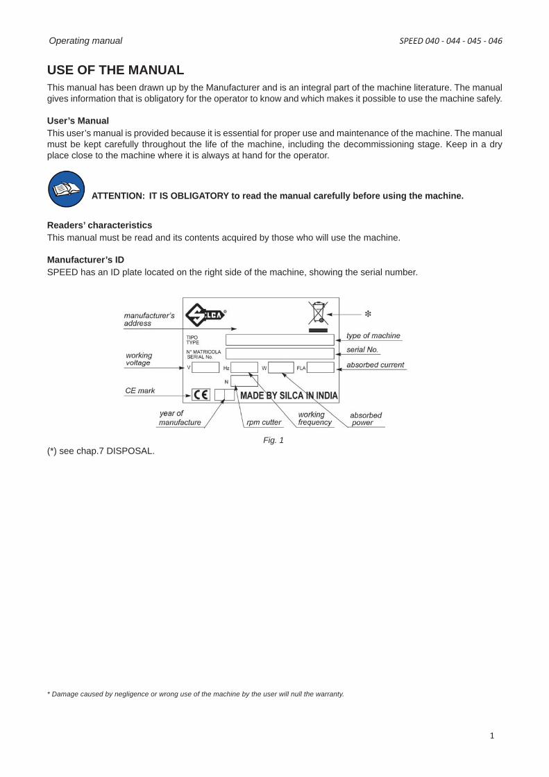
Manufacturer’s IDSPEED has an ID plate located on the right side of the machine, showing the serial number.
Fig. 1(*) see chap.7 DISPOSAL.
* Damage caused by negligence or wrong use of the machine by the user will null the warranty.
SPEED 040 - 044 - 045 - 046 Operating manual
1
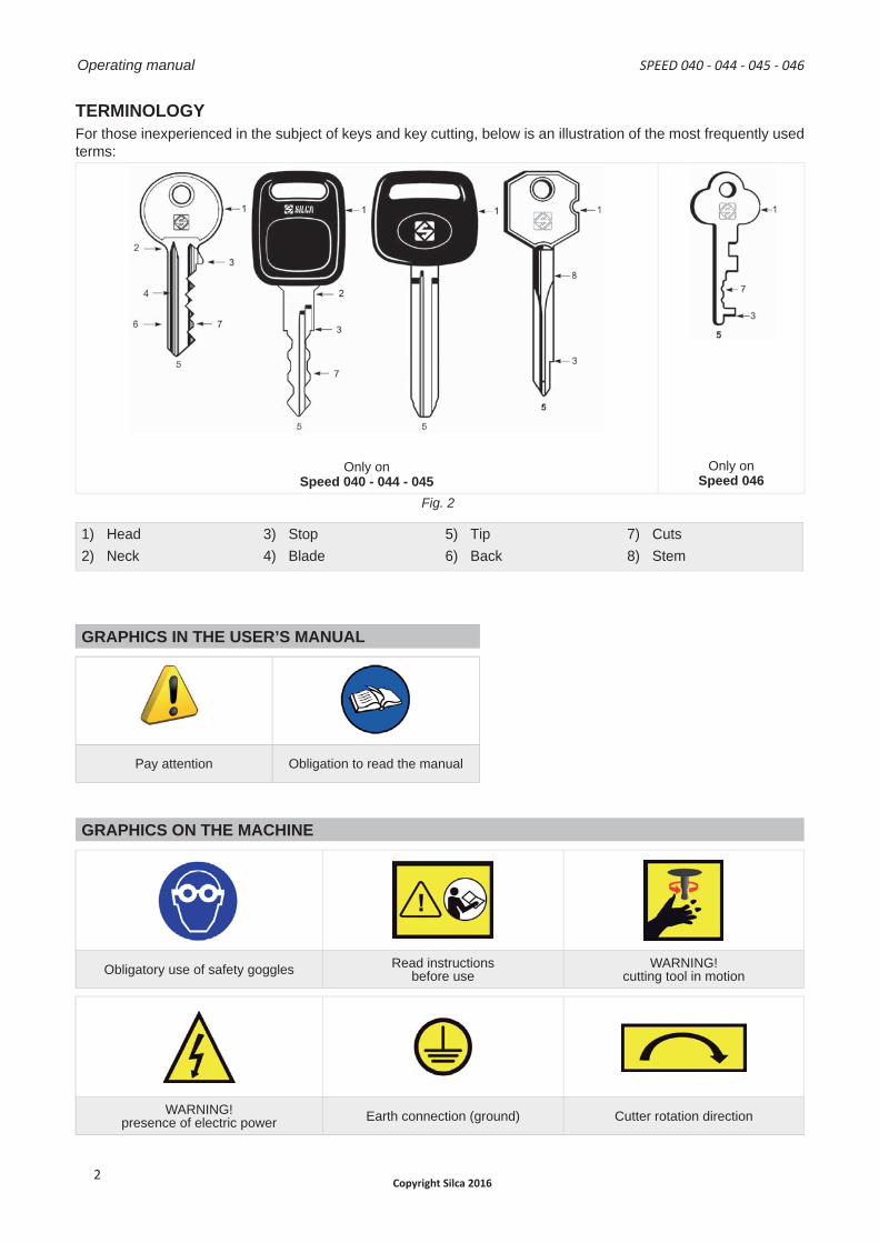
TERMINOLOGYFor those inexperienced in the subject of keys and key cutting, below is an illustration of the most frequently used terms:
Only onSpeed 040 - 044 - 045
Only onSpeed 046
Fig. 2
1) Head2) Neck
3) Stop4) Blade
5) Tip6) Back
7) Cuts8) Stem
GRAPHICS IN THE USER’S MANUAL
Pay attention Obligation to read the manual
GRAPHICS ON THE MACHINE
Obligatory use of safety goggles Read instructionsbefore use
WARNING!cutting tool in motion
WARNING!presence of electric power Earth connection (ground) Cutter rotation direction
Operating manual SPEED 040 - 044 - 045 - 046
Copyright Silca 20162
GENERAL WARNINGSThe SPEED line of machines are designed to the principles of European Standards (CE). Right from the design stage solutions have been adopted to eliminate hazards for the operator in all the stages of use: handling, regulation, use and maintenance.The materials used in manufacture and the components employed in using the SPEED line of machines are not dangerous and ensure that the machine complies with current standards.Silca S.p.A. has also experimented and applied numerous technical solutions that allow the key-cutting machine to optimize the quality of the cut keys.To guarantee maintaining these results over time, please follow the instructions below:• Observe the procedures described in this manual;
• Always use Original Silca Tools as they are designed to make the best of the SPEED line of machinesand provide quality key-cutting;
• Use Silca key blanks, made with top quality materials;
• Have the key-cutting machine checked periodically by an authorized Silca After-Sales Service Centre(list at the end of this manual);
• Always use Silca Original Spare Parts. Beware of imitations!
NORMAL USEThe SPEED line of key-cutting machines must be installed and used according to the rules and specifcations established by the manufacturer.Any other use different from that indicated in this manual will cause the forfeiture of all customers’ rights to make claims on Silca S.p.A. and may be an unknown source of hazard for the operator or third parties.
ATTENTION: negligent use or failure by the operator to observe the instructions in this manual are not covered by the warranty and the manufacturer declines any responsibility in such cases.
SAFETYThe key-cutting machine is built entirely to standards. The operations for which it has been designed areeasily carried out at no risk to the operator.The adoption of general safety precautions (wearing protective goggles) and observation of the instructionsprovided by the manufacturer in this manual eliminate all human error, unless deliberate.The key-cutting machine is designed with features which make it completely safe in all of its parts.• Cutter motor protection
ATTENTION: the cutter motor is protected from overheating by a device (inside the motor) that stops it whenit reaches a dangerous temperature.
This condition can occur when the machine motor is left on continuously, with high ambient temperatures or in severe working conditions. If the cutter motor overheats it cuts outautomatically. In such cases proceed as follows:a) turn off the master switch (H).b) let the motor cool for at least 2 hours then use the machine normally.
RESIDUAL RISKSThere are no further risks arising from the use of the machine.
SAFETY REGULATIONS• Always disconnect the machine when it is not in use or when performing maintenance operations.• Check the electrical wiring periodically; replace any wires that show signs of wear.• Always work with dry hands free of grease or oil.• Never pull hard on the power lead and make sure it does not come into contract with oil, sharp objects or heat.
Never remove the earth (ground) wire from the plug. Make sure the earth (ground) wire connection is sound.• Do not use the machine in dangerous environments (wet or damp).• All visitors, especially children, must stay at a safe distance from the machine and must never come into
contact with the electric wiring.
SPEED 040 - 044 - 045 - 046 Operating manual
Copyright Silca 2016 3
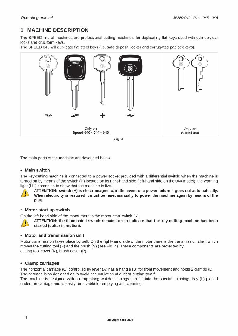
1 MACHINE DESCRIPTIONThe SPEED line of machines are professional cutting machine’s for duplicating fl at keys used with cylinder, car locks and cruciform keys.The SPEED 046 will duplicate fl at steel keys (i.e. safe deposit, locker and corrugated padlock keys).
Only onSpeed 040 - 044 - 045
Only onSpeed 046
Fig. 3
The main parts of the machine are described below:
• Main switchThe key-cutting machine is connected to a power socket provided with a differential switch; when the machine is turned on by means of the switch (H) located on its right-hand side (left-hand side on the 040 model), the warning light (H1) comes on to show that the machine is live.
ATTENTION: switch (H) is electromagnetic, in the event of a power failure it goes out automatically. When electricity is restored it must be reset manually to power the machine again by means of the plug.
• Motor start-up switchOn the left-hand side of the motor there is the motor start switch (K).
ATTENTION: the illuminated switch remains on to indicate that the key-cutting machine has been started (cutter in motion).
• Motor and transmission unitMotor transmission takes place by belt. On the right-hand side of the motor there is the transmission shaft which moves the cutting tool (F) and the brush (S) (see Fig. 4). These components are protected by:cutting tool cover (N), brush cover (P).
• Clamp carriagesThe horizontal carriage (C) controlled by lever (A) has a handle (B) for front movement and holds 2 clamps (D).The carriage is so designed as to avoid accumulation of dust or cutting swarf.The machine is designed with a ramp along which chippings can fall into the special chippings tray (L) placed under the carriage and is easily removable for emptying and cleaning.
Operating manual SPEED 040 - 044 - 045 - 046
Copyright Silca 20164

• Cutting unitThe cutting unit contains the actual working parts of the SPEED key-cutting machine, which operate together to cut and fi nish keys “read” from the originals. The working parts are described below:
• Cutting ToolThe cutting tool is in HSS super rapid steel and is protected by a special cover (N) to ensure safe operation.• Tracer pointThe tracer point (E) dedicated to reading the cuts on keys to be copied is housed on the left-hand side of the machine. Depth is easily regulated by means of the relevant centesimal ring nut (G).• ClampsThe clamps (D) are rotating and four-sided to allow perfect closure of the key placed on its back or profi le in the case of keys with symmetrical cuts (chap.5.1).• Clamp knobsThe clamps are locked by two ergonomic knobs (D1), which ensure perfect grip on the keys with only slight locking pressure.• GaugesNext to the clamps there is a rod (Q) with two gauge tabs to control key alignment for shoulder gauged keys.• BrushThe brush (S) is used to eliminate burrs from the cuts and is made of non-abrasive material.
SPEED 040 - 044 - 045 - 046 Operating manual
Copyright Silca 2016 5
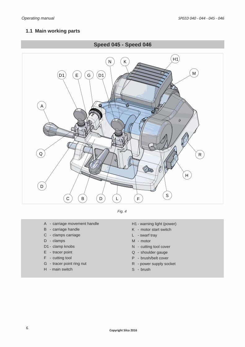
1.1 Main working parts
Speed 045 - Speed 046
B
C
D
B
C
D
Q
D1
D
C B
R
F
H
S D
A
G
H1
M
K N
D1
L
E
Fig. 4
A - carriage movement handleB - carriage handleC - clamps carriageD - clampsD1 - clamp knobsE - tracer pointF - cutting toolG - tracer point ring nutH - main switch
H1 - warning light (power)K - motor start switchL - swarf trayM - motorN - cutting tool coverQ - shoulder gaugeP - brush/belt coverR - power supply socketS - brush
Operating manual SPEED 040 - 044 - 045 - 046
Copyright Silca 20166
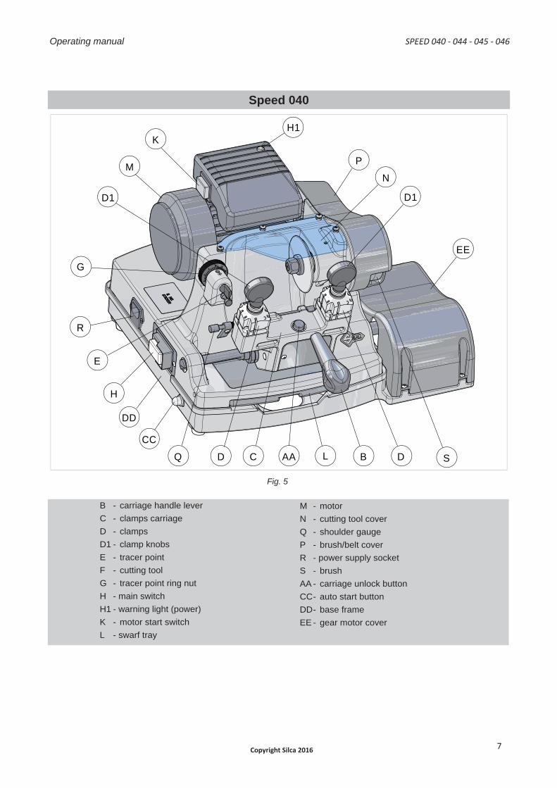
Speed 040
H
R
E
G
DD
CC
Q
EE
B D S L D
D1
M
K
P N
D1
H1
AA C
B C
A
B C
A
Fig. 5
B - carriage handle leverC - clamps carriageD - clampsD1 - clamp knobsE - tracer pointF - cutting toolG - tracer point ring nutH - main switchH1 - warning light (power)K - motor start switchL - swarf tray
M - motorN - cutting tool coverQ - shoulder gaugeP - brush/belt coverR - power supply socketS - brushAA - carriage unlock buttonCC - auto start buttonDD - base frameEE - gear motor cover
SPEED 040 - 044 - 045 - 046 Operating manual
Copyright Silca 2016 7
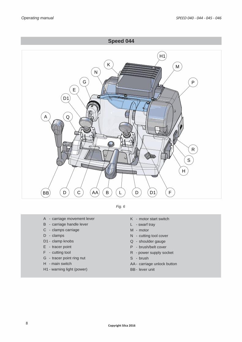
Speed 044
A
D1
E
G
N K
B C AA D
Q
BB D D1
H
S
M
H1
P
F
R
L
B
C
D
B
C
D
Fig. 6
A - carriage movement leverB - carriage handle leverC - clamps carriageD - clampsD1 - clamp knobsE - tracer pointF - cutting toolG - tracer point ring nutH - main switchH1 - warning light (power)
K - motor start switchL - swarf trayM - motorN - cutting tool coverQ - shoulder gaugeP - brush/belt coverR - power supply socketS - brushAA - carriage unlock buttonBB - lever unit
Operating manual SPEED 040 - 044 - 045 - 046
Copyright Silca 20168
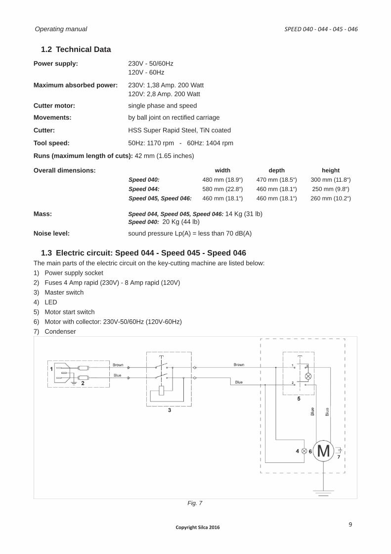
1.2 Technical DataPower supply: 230V - 50/60Hz
120V - 60Hz
Maximum absorbed power: 230V: 1,38 Amp. 200 Watt120V: 2,8 Amp. 200 Watt
Cutter motor: single phase and speed
Movements: by ball joint on rectifi ed carriage
Cutter: HSS Super Rapid Steel, TiN coated
Tool speed: 50Hz: 1170 rpm - 60Hz: 1404 rpm
Runs (maximum length of cuts): 42 mm (1.65 inches)
Overall dimensions: width depth heightSpeed 040: 480 mm (18.9“) 470 mm (18.5“) 300 mm (11.8“)Speed 044: 580 mm (22.8“) 460 mm (18.1“) 250 mm (9.8“)Speed 045, Speed 046: 460 mm (18.1“) 460 mm (18.1“) 260 mm (10.2“)
Mass: Speed 044, Speed 045, Speed 046: 14 Kg (31 lb) Speed 040: 20 Kg (44 lb)
Noise level: sound pressure Lp(A) = less than 70 dB(A)
1.3 Electric circuit: Speed 044 - Speed 045 - Speed 046The main parts of the electric circuit on the key-cutting machine are listed below:1) Power supply socket2) Fuses 4 Amp rapid (230V) - 8 Amp rapid (120V)3) Master switch4) LED5) Motor start switch6) Motor with collector: 230V-50/60Hz (120V-60Hz)7) Condenser
Fig. 7
SPEED 040 - 044 - 045 - 046 Operating manual
Copyright Silca 2016 9
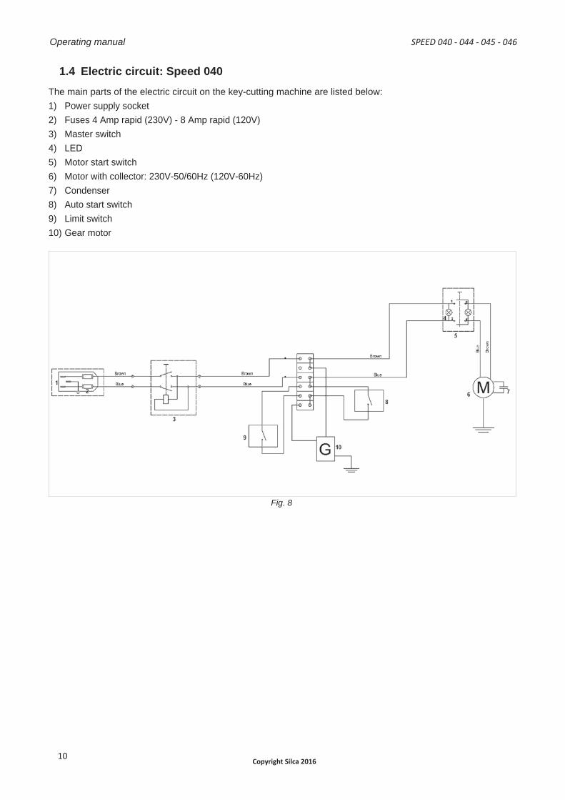
1.4 Electric circuit: Speed 040The main parts of the electric circuit on the key-cutting machine are listed below:1) Power supply socket2) Fuses 4 Amp rapid (230V) - 8 Amp rapid (120V)3) Master switch4) LED5) Motor start switch6) Motor with collector: 230V-50/60Hz (120V-60Hz)7) Condenser8) Auto start switch9) Limit switch10) Gear motor
Fig. 8
Operating manual SPEED 040 - 044 - 045 - 046
Copyright Silca 201610
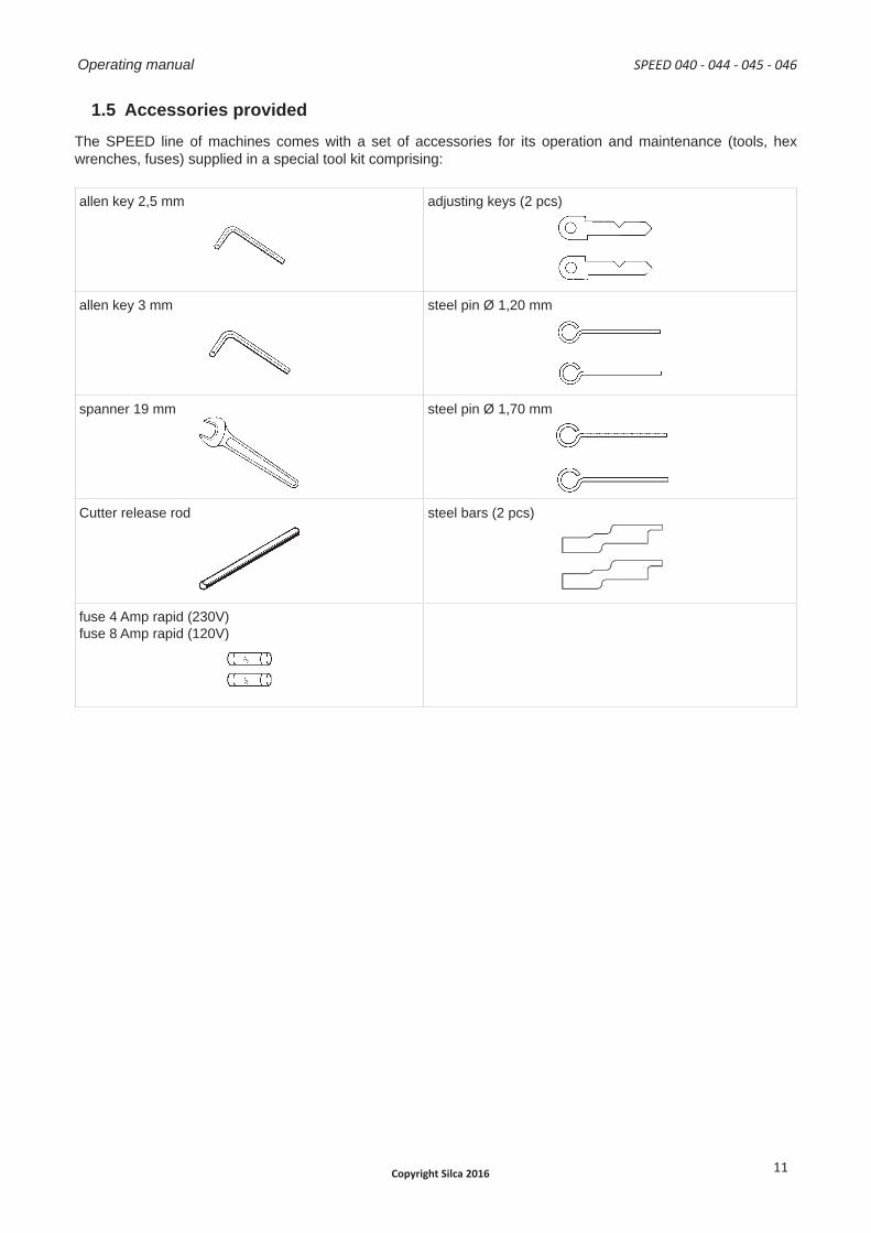
1.5 Accessories providedThe SPEED line of machines comes with a set of accessories for its operation and maintenance (tools, hex wrenches, fuses) supplied in a special tool kit comprising:
allen key 2,5 mm adjusting keys (2 pcs)
allen key 3 mm steel pin Ø 1,20 mm
spanner 19 mm steel pin Ø 1,70 mm
Cutter release rod steel bars (2 pcs)
fuse 4 Amp rapid (230V)fuse 8 Amp rapid (120V)
SPEED 040 - 044 - 045 - 046 Operating manual
Copyright Silca 2016 11
2 TRANSPORTThe SPEED key-cutting machine is easily transported and is not dangerous to handle.The packed machine can be carried by one person.
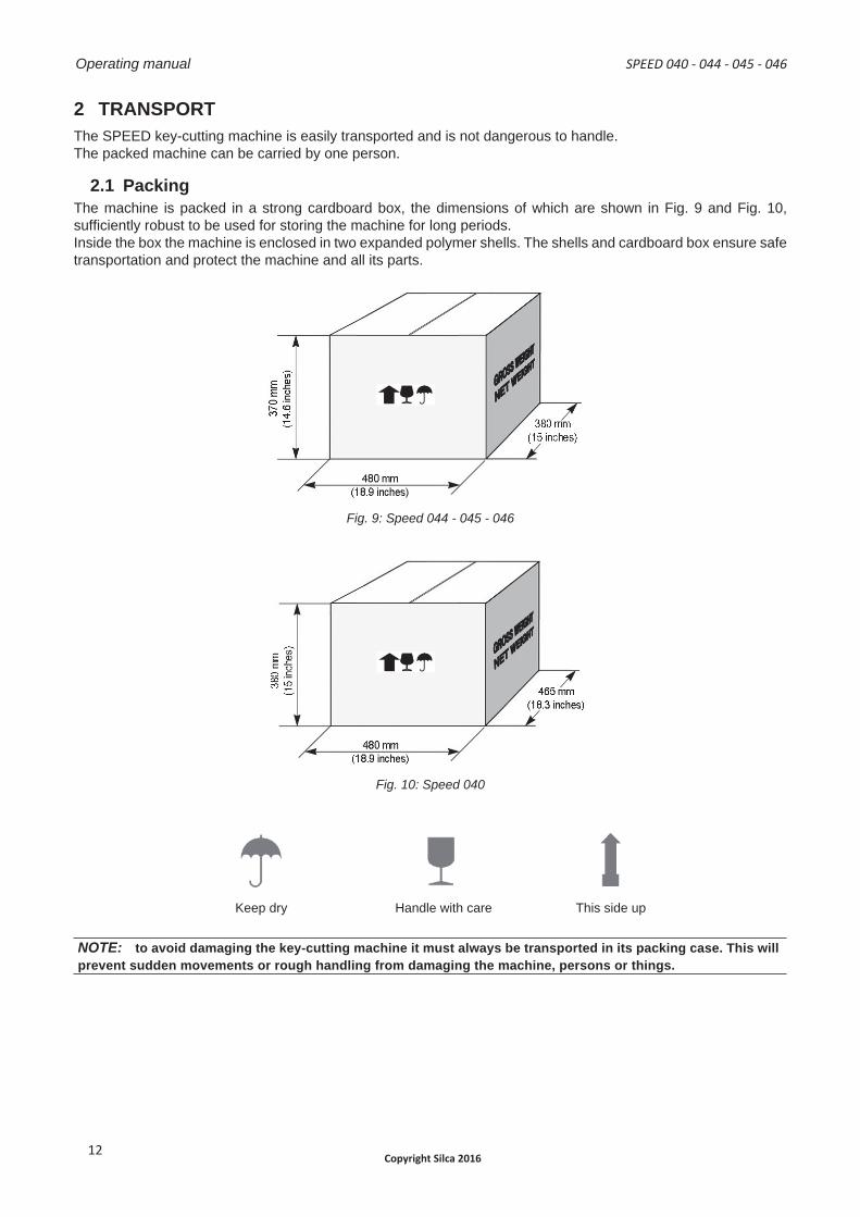
2.1 PackingThe machine is packed in a strong cardboard box, the dimensions of which are shown in Fig. 9 and Fig. 10, suffi ciently robust to be used for storing the machine for long periods.Inside the box the machine is enclosed in two expanded polymer shells. The shells and cardboard box ensure safe transportation and protect the machine and all its parts.
Fig. 9 : Speed 044 - 045 - 046
Fig. 10: Speed 040
Keep dry Handle with care This side up
NOTE: to avoid damaging the key-cutting machine it must always be transported in its packing case. This will prevent sudden movements or rough handling from damaging the machine, persons or things.
Operating manual SPEED 040 - 044 - 045 - 046
Copyright Silca 201612
2.2 UnpackingTo remove the machine from the packing box:1) Cut the straps with scissors and remove.2) Open the box without damaging it as it may be used again (e.g. removals, dispatch to themanufacturers for
repairs or servicing).3) Check the contents of the box, which should comprise:
- 1 SPEED key-cutting machine packed in a protective shell;- 1 set of documents, including: operating manual, spare parts list and warranty;- 1 carriage lever handle (2 lever handles on 045 and 046 models);- 1 power cable- 1 tool set;
4) Remove the key-cutting machine from the protective shell.
2.3 Handling the machineWhen the machine has been unpacked, place it directly on its workbench.This operation can be carried out by one person.
ATTENTION: fi rmly hold the base, and no other part, to lift and carry the machine.
SPEED 040 - 044 - 045 - 046 Operating manual
Copyright Silca 2016 13
3 MACHINE INSTALLATION AND PREPARATIONThe key-cutting machine can be installed by the purchaser and does not require any special skills. However, some checks and preparation for use need to be carried out by the operator.
3.1 Checking for damageThe SPEED key-cutting machine is solid and compact and will not normally damage if transport, unpacking and installation have all been carried out according to the instructions in this manual.However, it is always advisable to check that the machine has not suffered any damage.
3.2 Environmental conditionsTo ensure that the best use is made of the key-cutting machine, certain parameters must be borne in mind: damp, badly ventilated sites should be avoided.The ideal conditions for the machine are:
- temperature: between 10°C and 40°C (50°F and 104°F)- relative humidity: 60% circa; - room illumination: approximately 500 Lux.
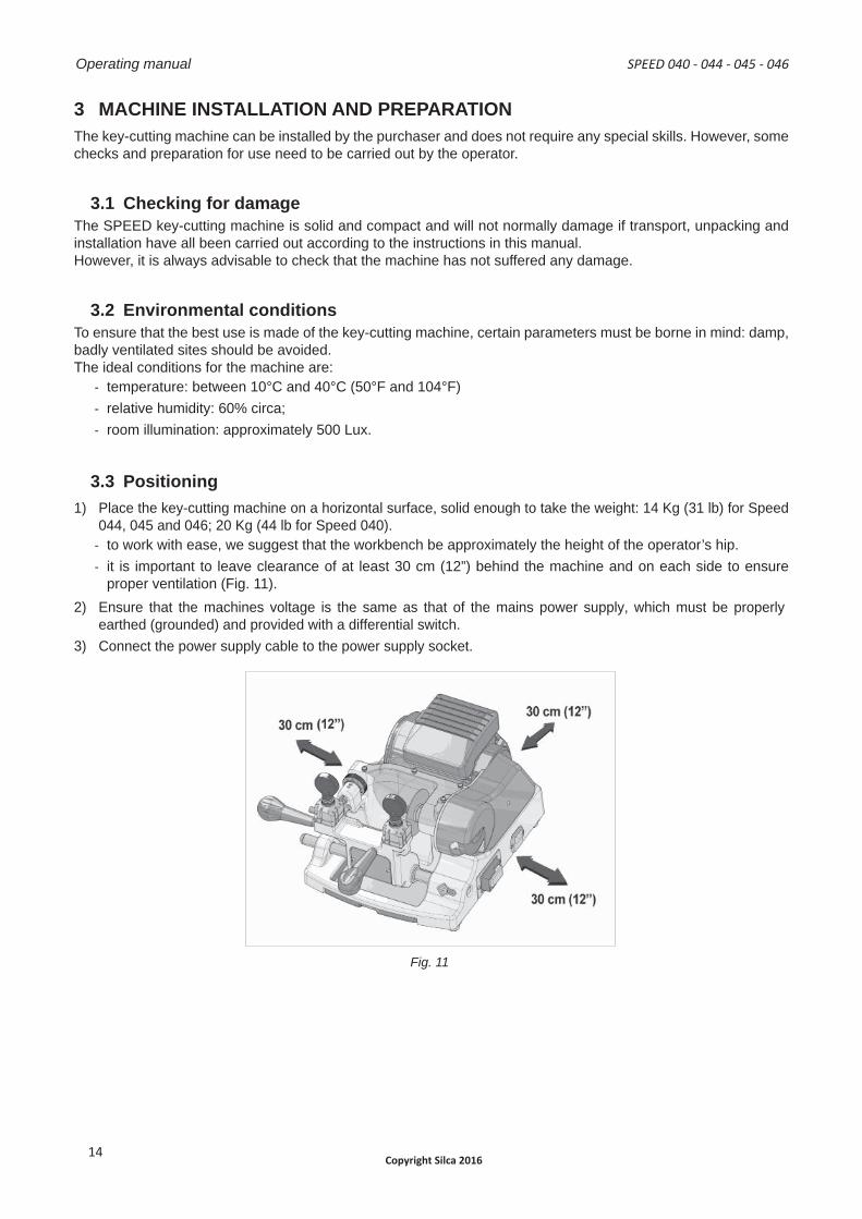
3.3 Positioning 1) Place the key-cutting machine on a horizontal surface, solid enough to take the weight: 14 Kg (31 lb) for Speed
044, 045 and 046; 20 Kg (44 lb for Speed 040).- to work with ease, we suggest that the workbench be approximately the height of the operator’s hip.- it is important to leave clearance of at least 30 cm (12”) behind the machine and on each side to ensure
proper ventilation (Fig. 11). 2) Ensure that the machines voltage is the same as that of the mains power supply, which must be properly
earthed (grounded) and provided with a differential switch.3) Connect the power supply cable to the power supply socket.
Fig. 11
Operating manual SPEED 040 - 044 - 045 - 046
Copyright Silca 201614
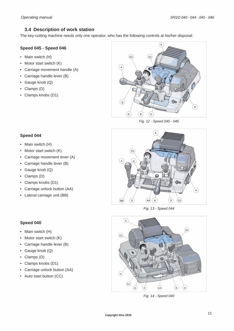
3.4 Description of work station The key-cutting machine needs only one operator, who has the following controls at his/her disposal:
Speed 045 - Speed 046
• Main switch (H)• Motor start switch (K)• Carriage movement handle (A)• Carriage handle lever (B)• Gauge knob (Q)• Clamps (D)• Clamps knobs (D1)
B
C
D
B
C
D
Q
D1
D B
H
D
A
K
D1
Fig. 12 - Speed 045 - 046
Speed 044
• Main switch (H)• Motor start switch (K)• Carriage movement lever (A)• Carriage handle lever (B)• Gauge knob (Q)• Clamps (D)• Clamps knobs (D1)• Carriage unlock button (AA)• Lateral carriage unit (BB)
A
D1
K
B AA D
Q
BB D D1
H
B
C
D
B
C
D
Fig. 13 - Speed 044
Speed 040
• Main switch (H)• Motor start switch (K)• Carriage handle lever (B)• Gauge knob (Q)• Clamps (D)• Clamps knobs (D1)• Carriage unlock button (AA)• Auto start button (CC)
H
CC
Q B D D
D1
K
D1
AA
B C
A
B C
A
Fig. 14 - Speed 040
SPEED 040 - 044 - 045 - 046 Operating manual
Copyright Silca 2016 15
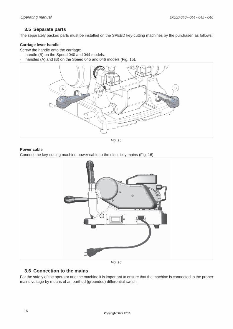
3.5 Separate partsThe separately packed parts must be installed on the SPEED key-cutting machines by the purchaser, as follows:
Carriage lever handleScrew the handle onto the carriage:- handle (B) on the Speed 040 and 044 models.- handles (A) and (B) on the Speed 045 and 046 models (Fig. 15).
B A
B
C
B
C
Fig. 15
Power cableConnect the key-cutting machine power cable to the electricity mains (Fig. 16).
Fig. 16
3.6 Connection to the mainsFor the safety of the operator and the machine it is important to ensure that the machine is connected to the proper mains voltage by means of an earthed (grounded) differential switch.
Operating manual SPEED 040 - 044 - 045 - 046
Copyright Silca 201616
4 MACHINE REGULATION AND UTILIZATION
4.1 Checking and calibrationThe cutting tool on the machine is the part used to cut the key blanks and should be periodically checked and replaced, if necessary.Every time the cutting tool is changed, and during periodical operational tests, check calibration.
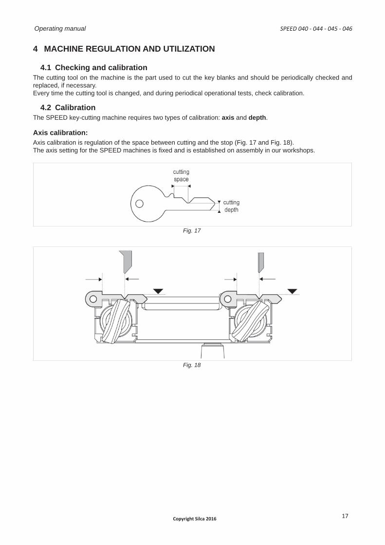
4.2 CalibrationThe SPEED key-cutting machine requires two types of calibration: axis and depth.
Axis calibration:Axis calibration is regulation of the space between cutting and the stop (Fig. 17 and Fig. 18).The axis setting for the SPEED machines is fi xed and is established on assembly in our workshops.
Fig. 17
Fig. 18
SPEED 040 - 044 - 045 - 046 Operating manual
Copyright Silca 2016 17
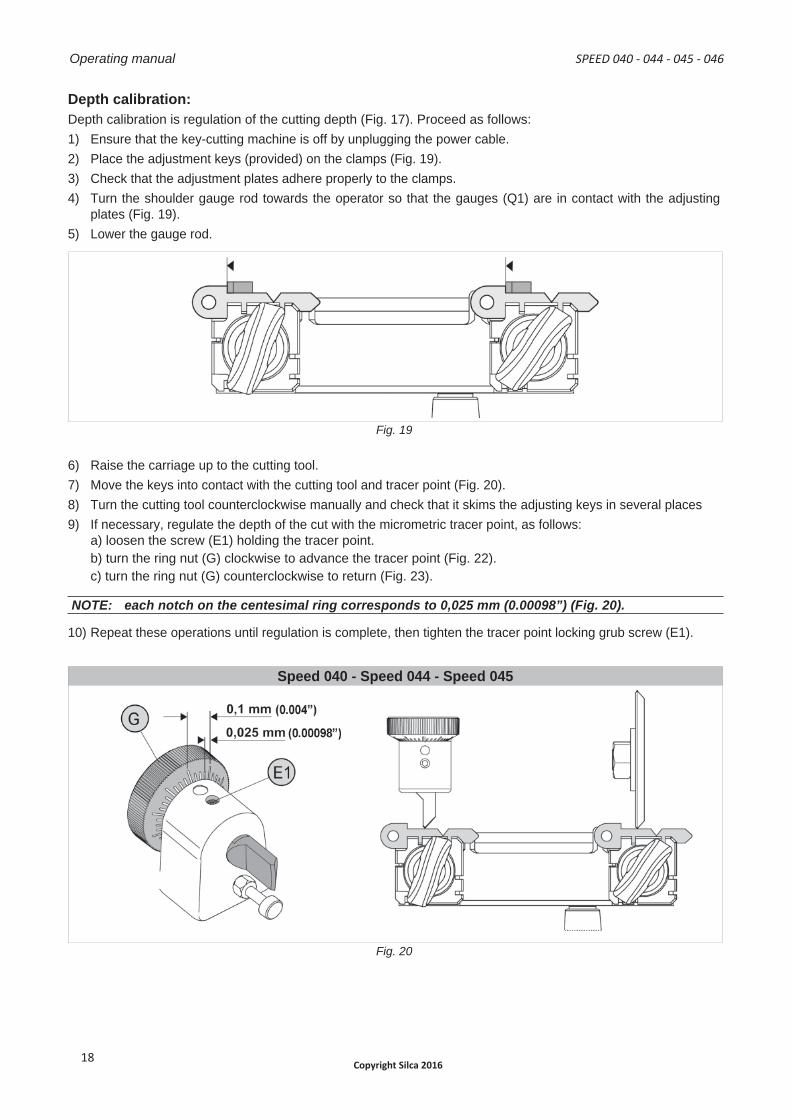
Depth calibration:Depth calibration is regulation of the cutting depth (Fig. 17). Proceed as follows:1) Ensure that the key-cutting machine is off by unplugging the power cable.2) Place the adjustment keys (provided) on the clamps (Fig. 19).3) Check that the adjustment plates adhere properly to the clamps.4) Turn the shoulder gauge rod towards the operator so that the gauges (Q1) are in contact with the adjusting
plates (Fig. 19).5) Lower the gauge rod.
Fig. 19
6) Raise the carriage up to the cutting tool.7) Move the keys into contact with the cutting tool and tracer point (Fig. 20).8) Turn the cutting tool counterclockwise manually and check that it skims the adjusting keys in several places9) If necessary, regulate the depth of the cut with the micrometric tracer point, as follows:
a) loosen the screw (E1) holding the tracer point.b) turn the ring nut (G) clockwise to advance the tracer point (Fig. 22).c) turn the ring nut (G) counterclockwise to return (Fig. 23).
NOTE: each notch on the centesimal ring corresponds to 0,025 mm (0.00098”) (Fig. 20).
10) Repeat these operations until regulation is complete, then tighten the tracer point locking grub screw (E1).
Speed 040 - Speed 044 - Speed 045
Fig. 20
Operating manual SPEED 040 - 044 - 045 - 046
Copyright Silca 201618
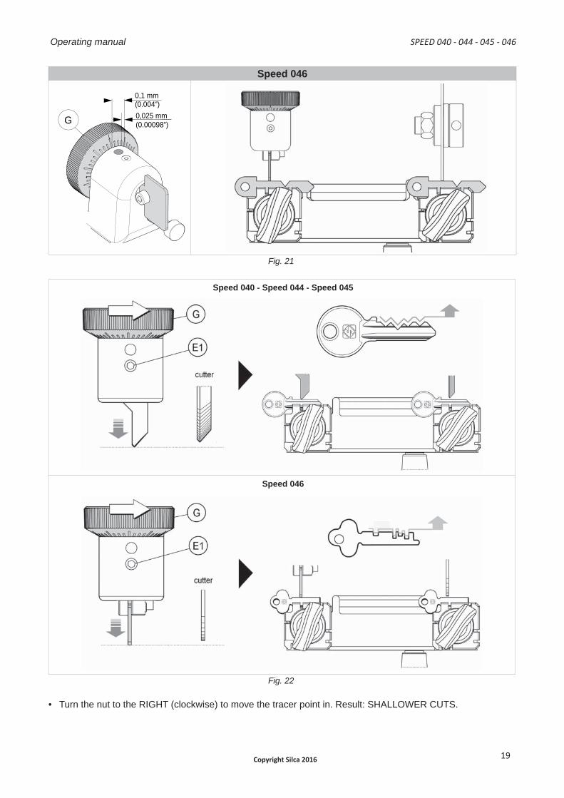
Speed 046
G 0,025 mm (0.00098”)
0,1 mm(0.004”)
Fig. 21
Speed 040 - Speed 044 - Speed 045
Speed 046
Fig. 22
• Turn the nut to the RIGHT (clockwise) to move the tracer point in. Result: SHALLOWER CUTS.
SPEED 040 - 044 - 045 - 046 Operating manual
Copyright Silca 2016 19
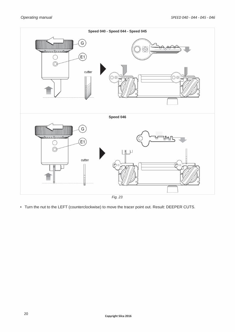
Speed 040 - Speed 044 - Speed 045
Speed 046
Fig. 23
• Turn the nut to the LEFT (counterclockwise) to move the tracer point out. Result: DEEPER CUTS.
Operating manual SPEED 040 - 044 - 045 - 046
Copyright Silca 201620
5 CUTTING OPERATIONS
ATTENTION: for complete safety during the cutting operations, take the following precautions:
• Always work with dry hands.
• Check that the machine is properly earthed.
• Wear protective goggles even if the machine has a protective shield over the cutting tool.
• Start the motor (switch K) only after completing the operations on the carriage (securing the keys,etc..).
• Keep hands away from the cutting tool in motion.
• Before duplicating, remove the gauges.
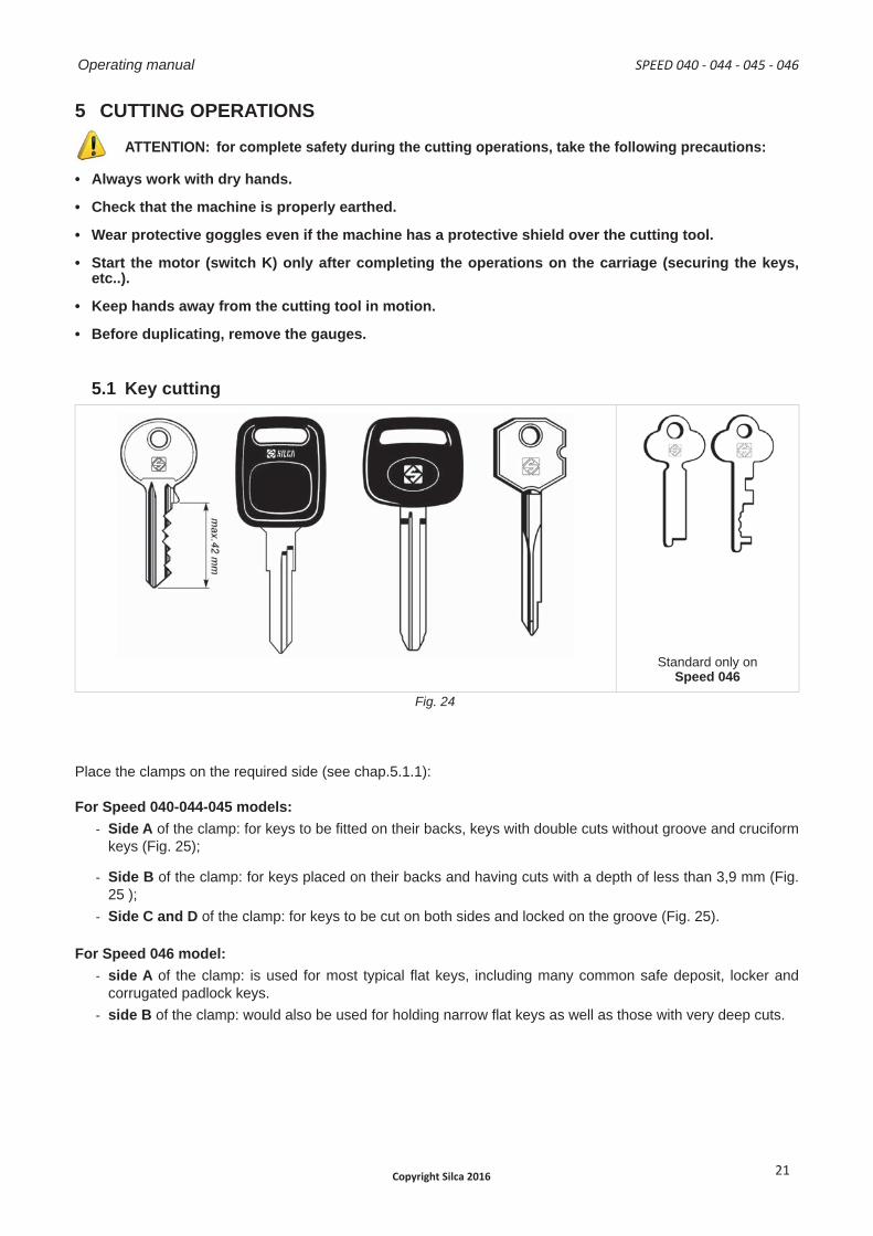
5.1 Key cutting
Standard only onSpeed 046
Fig. 24
Place the clamps on the required side (see chap.5.1.1):
For Speed 040-044-045 models:- Side A of the clamp: for keys to be fi tted on their backs, keys with double cuts without groove and cruciform
keys (Fig. 25);
- Side B of the clamp: for keys placed on their backs and having cuts with a depth of less than 3,9 mm (Fig. 25 );
- Side C and D of the clamp: for keys to be cut on both sides and locked on the groove (Fig. 25).
For Speed 046 model:- side A of the clamp: is used for most typical fl at keys, including many common safe deposit, locker and
corrugated padlock keys.- side B of the clamp: would also be used for holding narrow fl at keys as well as those with very deep cuts.
SPEED 040 - 044 - 045 - 046 Operating manual
Copyright Silca 2016 21
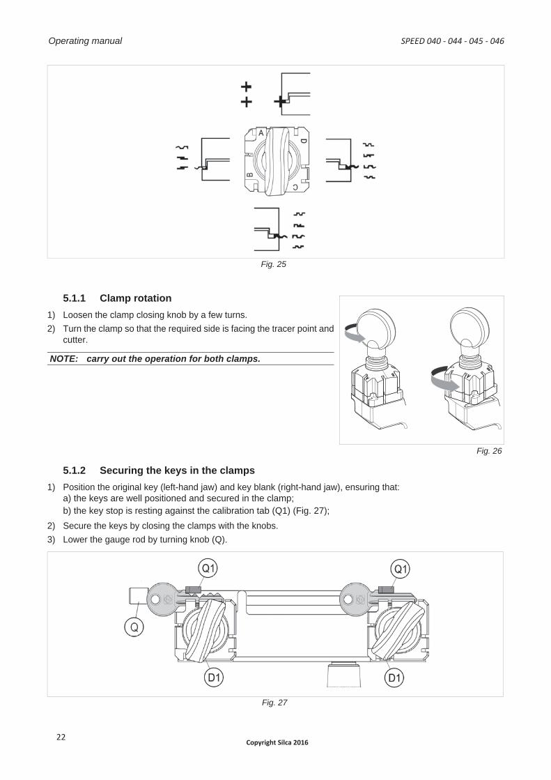
Fig. 25
5.1.1 Clamp rotation 1) Loosen the clamp closing knob by a few turns.2) Turn the clamp so that the required side is facing the tracer point and
cutter.
NOTE: carry out the operation for both clamps.
Fig. 26
5.1.2 Securing the keys in the clamps1) Position the original key (left-hand jaw) and key blank (right-hand jaw), ensuring that:
a) the keys are well positioned and secured in the clamp;b) the key stop is resting against the calibration tab (Q1) (Fig. 27);
2) Secure the keys by closing the clamps with the knobs.3) Lower the gauge rod by turning knob (Q).
Fig. 27
A ABBD
Operating manual SPEED 040 - 044 - 045 - 046
Copyright Silca 201622
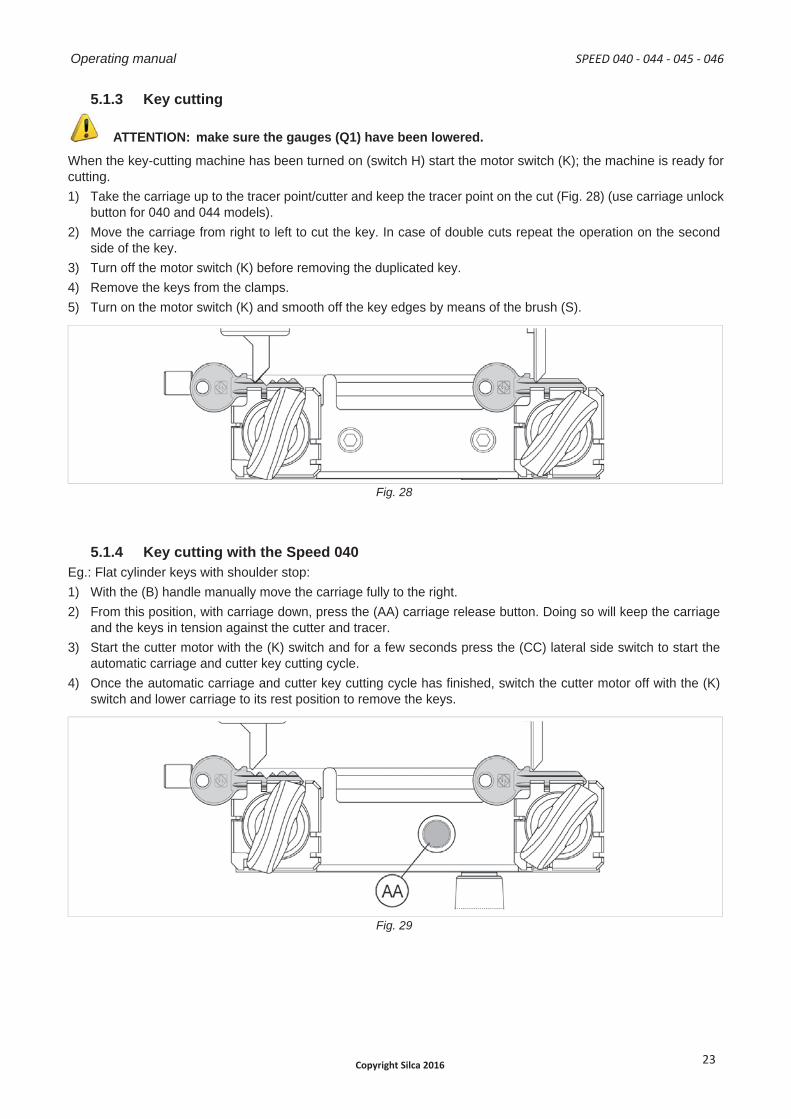
5.1.3 Key cutting
ATTENTION: make sure the gauges (Q1) have been lowered.
When the key-cutting machine has been turned on (switch H) start the motor switch (K); the machine is ready for cutting.1) Take the carriage up to the tracer point/cutter and keep the tracer point on the cut (Fig. 28) (use carriage unlock
button for 040 and 044 models).2) Move the carriage from right to left to cut the key. In case of double cuts repeat the operation on the second
side of the key.3) Turn off the motor switch (K) before removing the duplicated key.4) Remove the keys from the clamps.5) Turn on the motor switch (K) and smooth off the key edges by means of the brush (S).
Fig. 28
5.1.4 Key cutting with the Speed 040 Eg.: Flat cylinder keys with shoulder stop:1) With the (B) handle manually move the carriage fully to the right.2) From this position, with carriage down, press the (AA) carriage release button. Doing so will keep the carriage
and the keys in tension against the cutter and tracer.3) Start the cutter motor with the (K) switch and for a few seconds press the (CC) lateral side switch to start the
automatic carriage and cutter key cutting cycle.4) Once the automatic carriage and cutter key cutting cycle has fi nished, switch the cutter motor off with the (K)
switch and lower carriage to its rest position to remove the keys.
Fig. 29
SPEED 040 - 044 - 045 - 046 Operating manual
Copyright Silca 2016 23
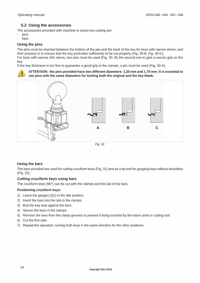
5.2 Using the accessoriesThe accessories provided with machine to assist key-cutting are:- pins- bars
Using the pinsThe pins must be inserted between the bottom of the jaw and the back of the key for keys with narrow stems, and their purpose is to ensure that the key protrudes suffi ciently to be cut properly (Fig. 30-B, Fig. 30-C).For keys with narrow, thin stems, two pins must be used (Fig. 30- B) the second one to give a secure grip on the key.If the key thickness is too fi ne to guarantee a good grip in the clamps, a pin must be used (Fig. 30-A).
ATTENTION: the pins provided have two different diameters: 1,20 mm and 1,70 mm; It is essential to use pins with the same diameters for locking both the original and the key blank.
Fig. 30
Using the barsThe bars provided are used for cutting cruciform keys (Fig. 31) and as a tip rest for gauging keys without shoulders (Fig. 32).
Cutting cruciform keys using barsThe cruciform keys (90°) can be cut with the clamps and the aid of the bars.
Positioning cruciform keys:1) Leave the gauges (Q1) in the idle position.2) Insert the bars into the slot in the clamps.3) Butt the key stop against the bars.4) Secure the keys in the clamps.5) Remove the bars from the clamp grooves to prevent it being touched by the tracer point or cutting tool.6) Cut the fi rst side.7) Repeat the operation, turning both keys in the same direction for the other positions.
Operating manual SPEED 040 - 044 - 045 - 046
Copyright Silca 201624
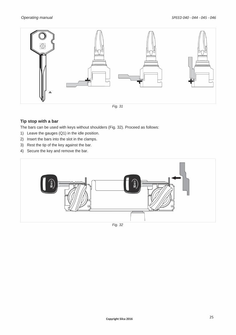
Fig. 31
Tip stop with a barThe bars can be used with keys without shoulders (Fig. 32). Proceed as follows:1) Leave the gauges (Q1) in the idle position.2) Insert the bars into the slot in the clamps.3) Rest the tip of the key against the bar.4) Secure the key and remove the bar.
Fig. 32
SPEED 040 - 044 - 045 - 046 Operating manual
Copyright Silca 2016 25
6 MAINTENANCE
ATTENTION: for repairs or replacement of parts for maintenance, the ‘CE’ mark is guaranteed only if original spare parts provided by the manufacturer are used.
Although the key-cutting machine does not require special maintenance, it is advisable to check and, if necessary, replace the parts subject to wear, such as: the belt, cutting tool, brush, tracer point. Replacement is simple and can be carried out by the operator.
CLEANINGKeep the carriage and clamps free of chippings from the cutting operations by cleaning with a dry brush.
ATTENTION: do not use compressed air!
ATTENTION: to keep the machine well maintained we recommend using protective oil, e.g. WD40 or similar, applied to the burnished mechanical parts. This prevents oxidation of the parts in question (clamps, guides, carriages...).
Before starting any type of maintenance (checks or replacements), read the instructions below:• Never carry out maintenance or servicing with the machine switched on.
• Always remove the mains plug.
• Follow all the instructions in the manual to the letter.
• Use original spare parts.
• Always check that any screws or nuts removed when replacing a piece are properly tightened.
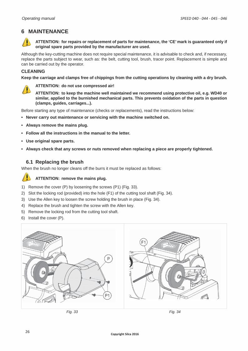
6.1 Replacing the brushWhen the brush no longer cleans off the burrs it must be replaced as follows:
ATTENTION: remove the mains plug.
1) Remove the cover (P) by loosening the screws (P1) (Fig. 33).2) Slot the locking rod (provided) into the hole (F1) of the cutting tool shaft (Fig. 34).3) Use the Allen key to loosen the screw holding the brush in place (Fig. 34).4) Replace the brush and tighten the screw with the Allen key.5) Remove the locking rod from the cutting tool shaft.6) Install the cover (P).
Fig. 33 Fig. 34
Operating manual SPEED 040 - 044 - 045 - 046
Copyright Silca 201626
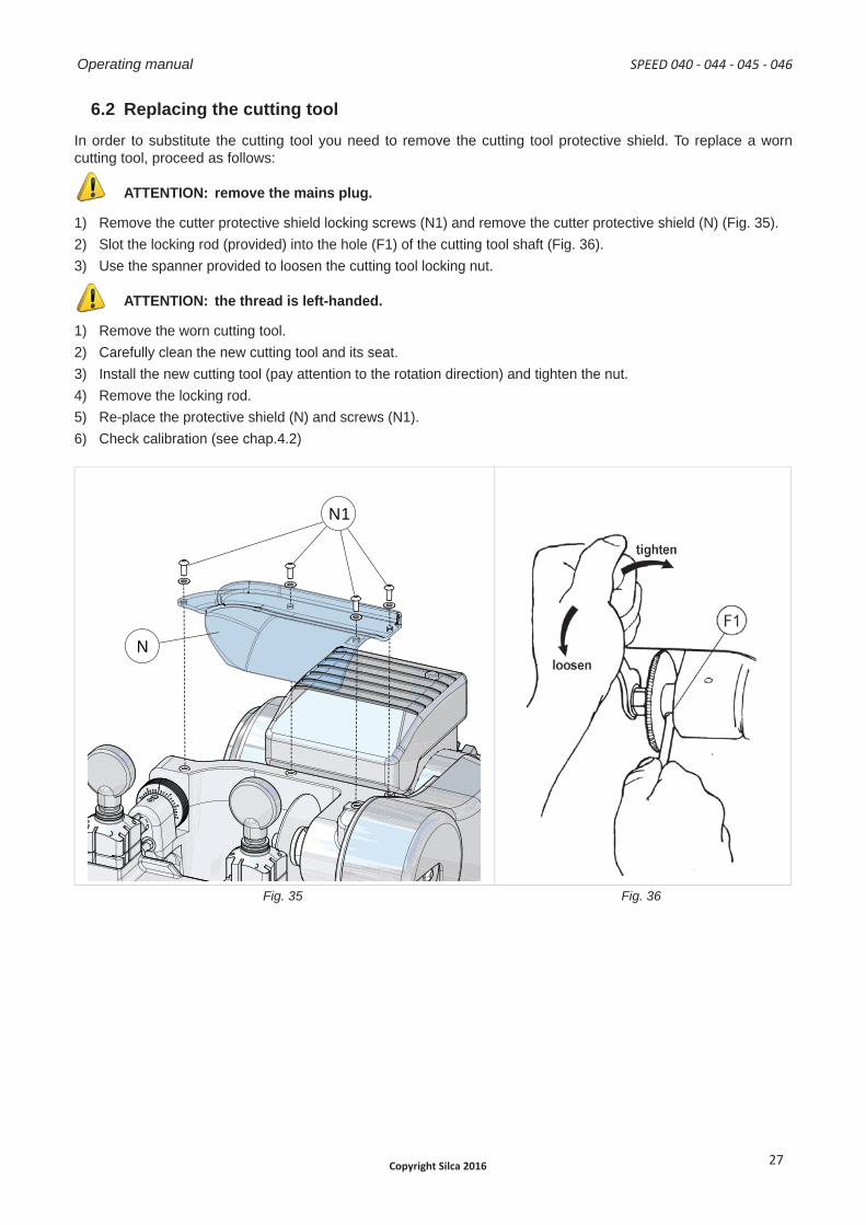
6.2 Replacing the cutting tool In order to substitute the cutting tool you need to remove the cutting tool protective shield. To replace a worn cutting tool, proceed as follows:
ATTENTION: remove the mains plug.
1) Remove the cutter protective shield locking screws (N1) and remove the cutter protective shield (N) (Fig. 35).2) Slot the locking rod (provided) into the hole (F1) of the cutting tool shaft (Fig. 36).3) Use the spanner provided to loosen the cutting tool locking nut.
ATTENTION: the thread is left-handed.
1) Remove the worn cutting tool.2) Carefully clean the new cutting tool and its seat.3) Install the new cutting tool (pay attention to the rotation direction) and tighten the nut.4) Remove the locking rod.5) Re-place the protective shield (N) and screws (N1).6) Check calibration (see chap.4.2)
N1
N
B
C
D
B
C
D
Fig. 35 Fig. 36
SPEED 040 - 044 - 045 - 046 Operating manual
Copyright Silca 2016 27
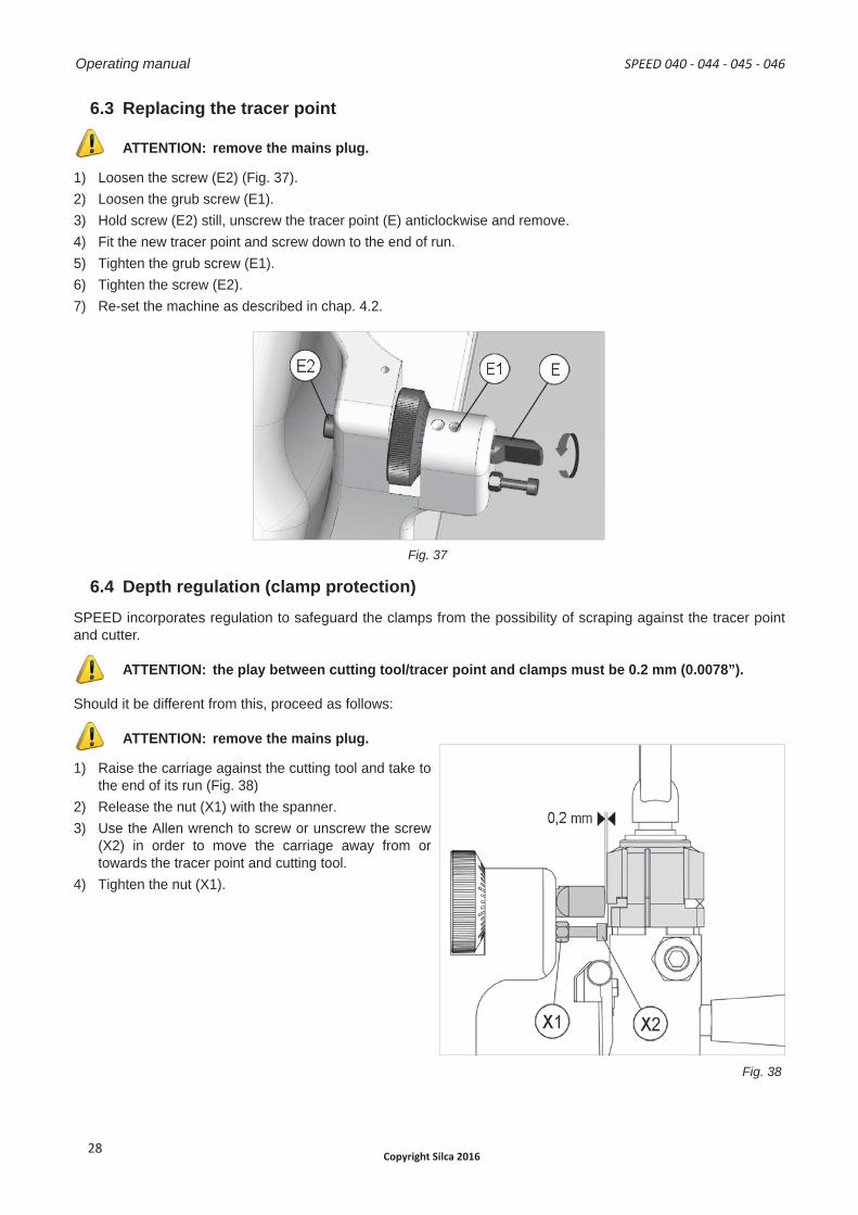
6.3 Replacing the tracer point
ATTENTION: remove the mains plug.
1) Loosen the screw (E2) (Fig. 37).2) Loosen the grub screw (E1).3) Hold screw (E2) still, unscrew the tracer point (E) anticlockwise and remove.4) Fit the new tracer point and screw down to the end of run.5) Tighten the grub screw (E1).6) Tighten the screw (E2).7) Re-set the machine as described in chap. 4.2.
Fig. 37
6.4 Depth regulation (clamp protection)SPEED incorporates regulation to safeguard the clamps from the possibility of scraping against the tracer point and cutter.
ATTENTION: the play between cutting tool/tracer point and clamps must be 0.2 mm (0.0078”).
Should it be different from this, proceed as follows:
ATTENTION: remove the mains plug.
1) Raise the carriage against the cutting tool and take tothe end of its run (Fig. 38)
2) Release the nut (X1) with the spanner.3) Use the Allen wrench to screw or unscrew the screw
(X2) in order to move the carriage away from ortowards the tracer point and cutting tool.
4) Tighten the nut (X1).
Fig. 38
Operating manual SPEED 040 - 044 - 045 - 046
Copyright Silca 201628
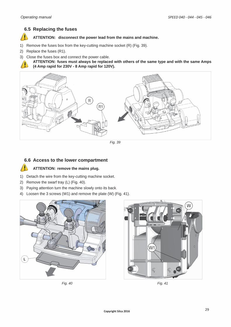
6.5 Replacing the fusesATTENTION: disconnect the power lead from the mains and machine.
1) Remove the fuses box from the key-cutting machine socket (R) (Fig. 39).2) Replace the fuses (R1).3) Close the fuses box and connect the power cable.
ATTENTION: fuses must always be replaced with others of the same type and with the same Amps (4 Amp rapid for 230V - 8 Amp rapid for 120V).
Fig. 39
6.6 Access to the lower compartmentATTENTION: remove the mains plug.
1) Detach the wire from the key-cutting machine socket.2) Remove the swarf tray (L) (Fig. 40).3) Paying attention turn the machine slowly onto its back.4) Loosen the 3 screws (W1) and remove the plate (W) (Fig. 41).
L
B
C
D
B
C
D
Fig. 40 Fig. 41
SPEED 040 - 044 - 045 - 046 Operating manual
Copyright Silca 2016 29
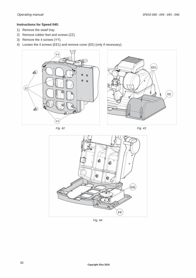
Instructions for Speed 040:1) Remove the swarf tray.2) Remove rubber feet and screws (ZZ).3) Remove the 4 screws (YY).4) Loosen the 4 screws (EE1) and remove cover (EE) (only if necessary).
ZZ
YY
YY
EE1
EE
B
C
D
Fig. 42 Fig. 43
FF
GG
Fig. 44
Operating manual SPEED 040 - 044 - 045 - 046
Copyright Silca 201630
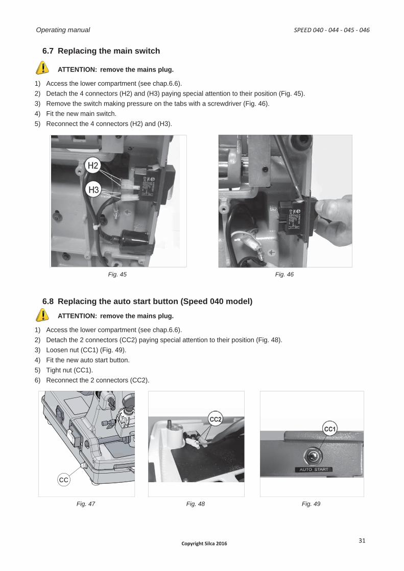
6.7 Replacing the main switch
ATTENTION: remove the mains plug.
1) Access the lower compartment (see chap.6.6).2) Detach the 4 connectors (H2) and (H3) paying special attention to their position (Fig. 45).3) Remove the switch making pressure on the tabs with a screwdriver (Fig. 46).4) Fit the new main switch.5) Reconnect the 4 connectors (H2) and (H3).
Fig. 45 Fig. 46
6.8 Replacing the auto start button (Speed 040 model)ATTENTION: remove the mains plug.
1) Access the lower compartment (see chap.6.6).2) Detach the 2 connectors (CC2) paying special attention to their position (Fig. 48).3) Loosen nut (CC1) (Fig. 49).4) Fit the new auto start button.5) Tight nut (CC1).6) Reconnect the 2 connectors (CC2).
CC
B C
A
Fig. 47 Fig. 48 Fig. 49
SPEED 040 - 044 - 045 - 046 Operating manual
Copyright Silca 2016 31
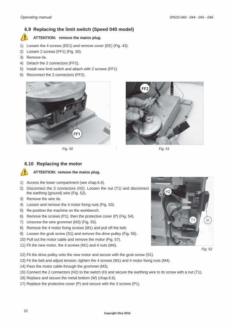
6.9 Replacing the limit switch (Speed 040 model)ATTENTION: remove the mains plug.
1) Loosen the 4 screws (EE1) and remove cover (EE) (Fig. 43).2) Loosen 2 screws (FF1) (Fig. 50).3) Remove tie.4) Detach the 2 connectors (FF2).5) Install new limit switch and attach with 2 screws (FF1)6) Reconnect the 2 connectors (FF2).
Fig. 50 Fig. 51
6.10 Replacing the motorATTENTION: remove the mains plug.
1) Access the lower compartment (see chap.6.6).2) Disconnect the 2 connectors (H2). Loosen the nut (T1) and disconnect
the earthing (ground) wire (Fig. 52).3) Remove the wire tie.4) Loosen and remove the 4 motor fi xing nuts (Fig. 53).5) Re-position the machine on the workbench.6) Remove the screws (P1), then the protective cover (P) (Fig. 54).7) Unscrew the wire grommet (M3) (Fig. 55).8) Remove the 4 motor fi xing screws (M1) and pull off the belt.9) Loosen the grub screw (S1) and remove the drive pulley (Fig. 56).10) Pull out the motor cable and remove the motor (Fig. 57).11) Fit the new motor, the 4 screws (M1) and 4 nuts (M4).
Fig. 52 12) Fit the drive pulley onto the new motor and secure with the grub screw (S1).13) Fit the belt and adjust tension, tighten the 4 screws (M1) and 4 motor fi xing nuts (M4).14) Pass the motor cable through the grommet (M3).15) Connect the 2 connectors (H2) to the switch (H) and secure the earthing wire to its screw with a nut (T1).16) Replace and secure the metal bottom (W) (chap.6.6).17) Replace the protective cover (P) and secure with the 3 screws (P1).
Operating manual SPEED 040 - 044 - 045 - 046
Copyright Silca 201632
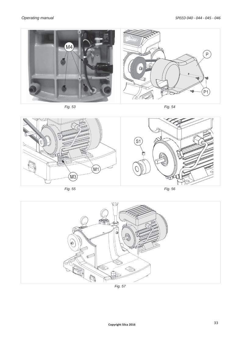
Fig. 53 Fig. 54
Fig. 55 Fig. 56
Fig. 57
SPEED 040 - 044 - 045 - 046 Operating manual
Copyright Silca 2016 33
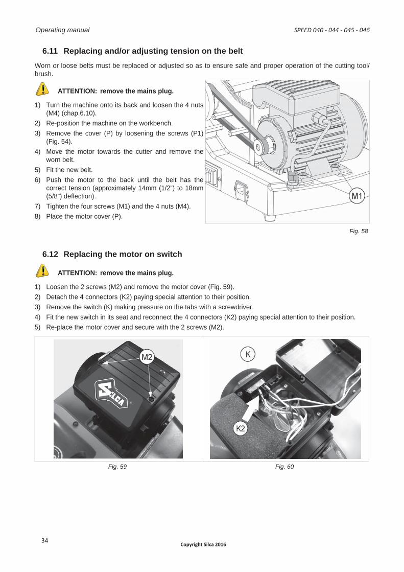
6.11 Replacing and/or adjusting tension on the beltWorn or loose belts must be replaced or adjusted so as to ensure safe and proper operation of the cutting tool/ brush.
ATTENTION: remove the mains plug.
1) Turn the machine onto its back and loosen the 4 nuts(M4) (chap.6.10).
2) Re-position the machine on the workbench.3) Remove the cover (P) by loosening the screws (P1)
(Fig. 54).4) Move the motor towards the cutter and remove the
worn belt.5) Fit the new belt.6) Push the motor to the back until the belt has the
correct tension (approximately 14mm (1/2”) to 18mm(5/8”) defl ection).
7) Tighten the four screws (M1) and the 4 nuts (M4).8) Place the motor cover (P).
Fig. 58
6.12 Replacing the motor on switch
ATTENTION: remove the mains plug.
1) Loosen the 2 screws (M2) and remove the motor cover (Fig. 59).2) Detach the 4 connectors (K2) paying special attention to their position.3) Remove the switch (K) making pressure on the tabs with a screwdriver.4) Fit the new switch in its seat and reconnect the 4 connectors (K2) paying special attention to their position.5) Re-place the motor cover and secure with the 2 screws (M2).
Fig. 59 Fig. 60
Operating manual SPEED 040 - 044 - 045 - 046
Copyright Silca 201634
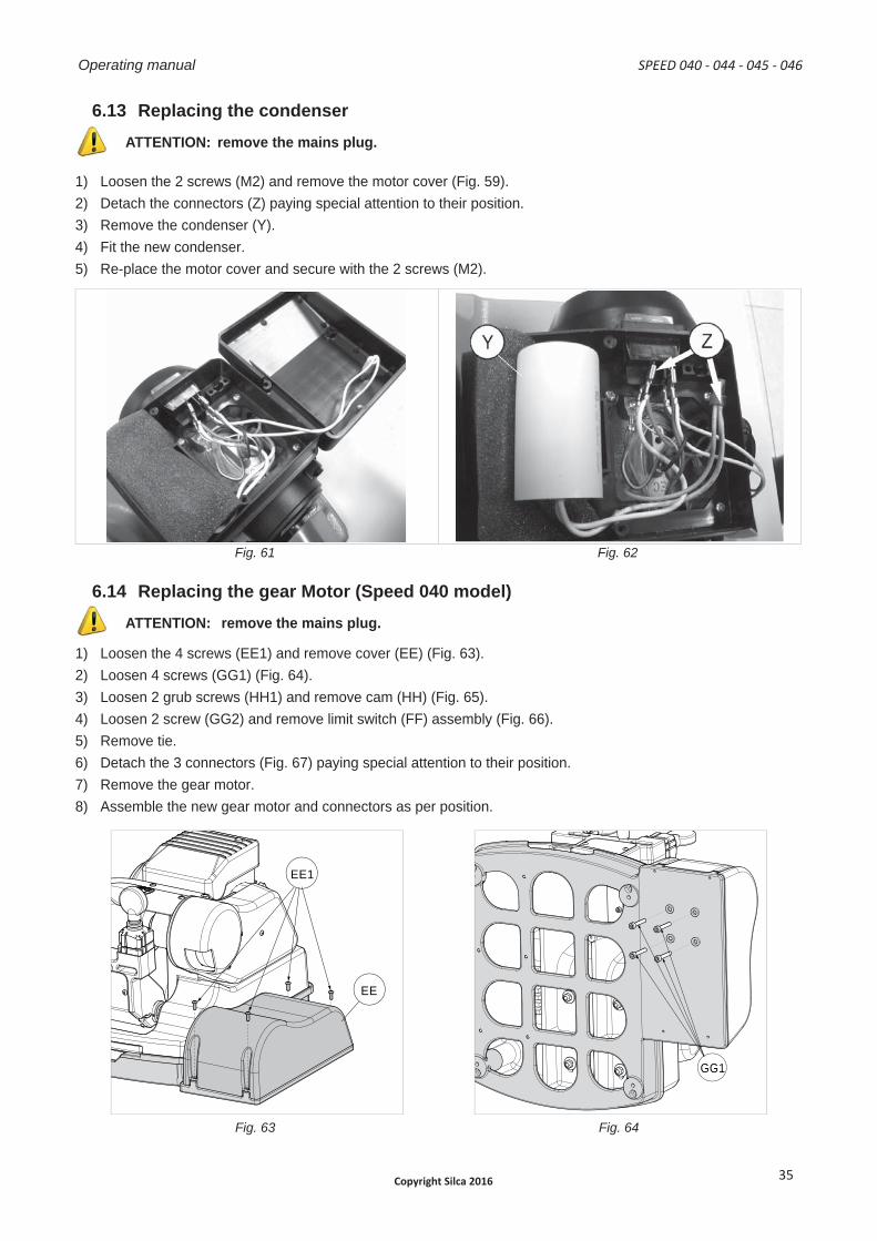
6.13 Replacing the condenserATTENTION: remove the mains plug.
1) Loosen the 2 screws (M2) and remove the motor cover (Fig. 59).2) Detach the connectors (Z) paying special attention to their position.3) Remove the condenser (Y).4) Fit the new condenser.5) Re-place the motor cover and secure with the 2 screws (M2).
Fig. 61 Fig. 62
6.14 Replacing the gear Motor (Speed 040 model)ATTENTION: remove the mains plug.
1) Loosen the 4 screws (EE1) and remove cover (EE) (Fig. 63).2) Loosen 4 screws (GG1) (Fig. 64).3) Loosen 2 grub screws (HH1) and remove cam (HH) (Fig. 65).4) Loosen 2 screw (GG2) and remove limit switch (FF) assembly (Fig. 66).5) Remove tie.6) Detach the 3 connectors (Fig. 67) paying special attention to their position.7) Remove the gear motor.8) Assemble the new gear motor and connectors as per position.
EE1
EE
B
C
D
GG1
Fig. 63 Fig. 64
SPEED 040 - 044 - 045 - 046 Operating manual
Copyright Silca 2016 35
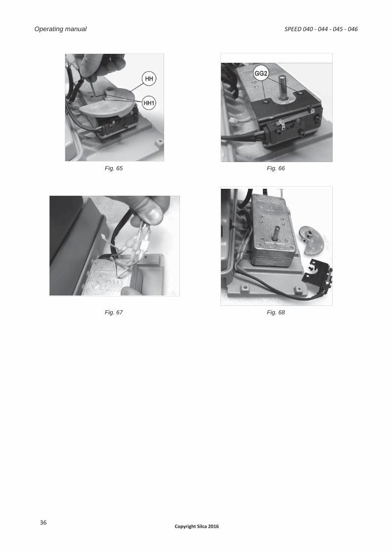
Fig. 65 Fig. 66
Fig. 67 Fig. 68
Operating manual SPEED 040 - 044 - 045 - 046
Copyright Silca 201636
7 DISPOSAL
For correct disposal please refer to current standards.
INFORMATION FOR USERS OF PROFESSIONAL EQUIPMENT
From “Actuation of Directive 2012/19/EU regarding Waste Electrical and Electronic Equipment (WEEE)”
The symbol of a crossed waste bin found on equipment or its packing indicates that at the end of the product’s useful life it must be collected separately from other waste so that it can be properly treated and recycled.In particular, separate collection of this professional equipment when no longer in use is organised and managed:
a) directly by the user when the equipment was placed on the market before 31 December 2010 and theuser personally decides to eliminate it without replacing it with new equivalent equipment designed for the same use;
b) by the manufacturer, that is to say the subject which was the fi rst to introduce and market new equipmentthat replaces previous equipment, when the user decides to eliminate equipment placed on the marketbefore 31 December 2010 at the end of its useful life and replace it with an equivalent product designedfor the same use. In this latter case the user may ask the manufacturer to collect the existing equipment;
c) by the manufacturer, that is to say the subject which was the fi rst to introduce and market new equipmentthat replaces previous equipment, if it was placed on the market after 31 December 2010;
Suitable separate collection for the purpose of forwarding discarded equipment for recycling, treatment or disposal in an environmentally friendly way helps to avoid possible negative effects on the environment and human health and encourages re-use and/or recycling of the materials making up the equipment.
The sanctions currently provided for by law shall apply to users who dispose of products in unauthorised ways.
SPEED 040 - 044 - 045 - 046 Operating manual
Copyright Silca 2016 37
CE DECLARATION OF MACHINE COMPLIANCE
Declares under its own responsibility that the Key-cutting machine model
SPEED 040 - SPEED 044 - SPEED 045 - SPEED 046
complies with the requirements of the following European Directives:
European Union DIRECTIVE 2006/42/CE (Machines) and with the ENISO 12100 : 2010 Standards
European Union DIRECTIVE 2004/108/CE (Electromagnetic Compatibility) and with the EN 60034 – 1 : 2010 Standards
European Union DIRECTIVE 2006/95/CE (Low Voltage) | 16 |and with the EN 60204 – 1 : 2006 / A1: 2009 Standards
Claudio Tomasella of the Silca S.p.A. Research & Development Division is authorized to create a Technical File.
General Manager Basic Production Center
Check out the collection of power tools we offer.