Embed Size (px)
Citation preview

International Journal Of Core Engineering & Management (ISSN: 2348-9510) Special Issue, NCIAEE-2017, St. Johns College of Engineering and Technology, Yemmiganur
159
ADVANCED CONTROL SCHEME FOR AN IPM SYNCHRONOUS GENERATOR-BASED GEARLESS VARIABLE SPEED WIND TURBINE
N.Rajesh Kumar Gowd1 J.Lakshmi Prasad 2 G.Subba Rao Gupta3
Lecturer,Dept.of EEE,Sri Krishnadevaraya university College of Engineering & Technology,
Ananthapuramu, A.P,India. Assistant Prof ,Dept.of EEE ,Anantha lakshimi Institute of Technology & science,
Ananthapuramu, A.P,India. Assistant Prof ,Dept.of EEE ,Anantha lakshimi Institute of Technology & science,
Ananthapuramu, A.P,India
Abstract
Currently, variable speed wind turbine technologies dominate the world market share due to their advantages over fixed speed generation such as increased energy capture, operation at maximum power point, improved efficiency, and power quality Most of these wind turbines use doubly fed induction generator (DFIG) based variable speed wind turbines with gearbox, the use of gearbox in these turbines to couple the generator with the turbine causes problems. Moreover, the gearbox requires regular maintenance as it suffers from faults and malfunctions the use of permanent magnet in the rotor of the PMSG makes it unnecessary to supply magnetizing current through the stator for constant air-gap flux. Therefore, it can operate at higher power factor and efficiency the previous works done on PMSG based wind turbines are mostly based on surface permanent magnet-type synchronous generator. Very few works have been done so far on interior PMSG-based wind turbines, which can produce additional power by exploiting their rotor saliency This project proposes a direct control strategy for an interior permanent magnet synchronous generator-based variable speed wind turbine. In this scheme, the requirement of the continuous rotor position is eliminated as all the calculations are done in the stator reference frame. Moreover, the gearbox requires regular maintenance as it suffers from faults and malfunctions Variable speed wind turbine using permanent magnet synchronous generator (PMSG) without gearbox can enhance the performance of the wind energy conversion system. The control of PMSG-based variable speed wind turbine with switch-mode rectifier has the merit of simple structure and low cost because of only one controllable switch. In this paper, a direct control strategy is implemented where coordinate transformations are not required as all the calculations are done in stator reference frame. Thus, the requirement of continuous rotor position (θr) is eliminated. This method is inherently sensorless and have several advantages compared with the traditional indirect vector control scheme. However, a speed sensor is required only for speed control loop. Therefore, a sensorless speed estimator is proposed and implemented in this proposed system to estimate the speed without a mechanical sensor. The combination of the

International Journal Of Core Engineering & Management (ISSN: 2348-9510) Special Issue, NCIAEE-2017, St. Johns College of Engineering and Technology, Yemmiganur
160
hysteresis control block (torque and flux comparators) and the switching logic block eliminates the need for a traditional PW modulator.
I. OVERVIEW The wind energy will play a major role to meet the renewable energy target worldwide, to reduce the dependency on fossil fuel, and to minimize the impact of climate change. Currently, variable speed wind turbine technologies dominate the world market share due to their advantages over fixed speed generation such as increased energy capture, operation at maximum power point, improved efficiency, and power quality. Most of these wind turbines use doubly fed induction generator (DFIG) based variable speed wind turbines with gearbox. This technology has an advantage of having power electronic converter with reduced power rating (30% of full rated power) as the converter is connected to the rotor circuit. However, the use of gearbox in these turbines to couple the generator with the turbine causes problems. Moreover, the gearbox requires regular maintenance as it suffers from faults and malfunctions. Variable speed wind turbine using permanent magnet synchronous generator (PMSG) without gearbox can enhance the performance of the wind energy conversion system. The use of permanent magnet in the rotor of the PMSG makes it unnecessary to supply magnetizing current through the stator for constant air-gap flux. Therefore, it can operate at higher power factor and efficiency. The previous works done on PMSG based wind turbines are mostly based on surface permanent magnet-type synchronous generator. Very few works have been done so far on interior PMSG-based wind turbines, which can produce additional power by exploiting their rotor saliency. It can also be operated over a wide speed range (more than rated speed) by flux weakening, which will allow constant power-like operation at speeds higher than the rated speed. This work is based on interior permanent magnet-type synchronous generator-based variable speed wind turbine. are different control strategies reported in the literature for permanent synchronous generator-based variable speed wind turbine such as switch-mode boost rectifier (uncontrolled diode rectifier cascaded by a boost dc–dc chopper), three-switch pulse width modulation (PWM) rectifier, and six-switch vector-controlled PWM rectifier. The control of PMSG-based variable speed wind turbine with switch-mode rectifier has the merit of simple structure and low cost because of only one controllable switch. However, it lacks the ability to control generator power factor and introduces high harmonic distortion, which affects the generator efficiency. Moreover, this scheme introduces high voltage surge on the generator winding which can reduce the life span of the generator. Traditional vector control scheme is widely used in modern PMSG-based variable speed wind energy conversion system. In this scheme, the generator torque is controlled indirectly through current control. The output of the speed controller generates the d and q–axes current references, which are in the rotor reference frame. The generator developed torque is controlled by regulating the currents and according to the generator torque equation. For high performance, the current control is normally executed at the rotor reference frame, which rotates with the rotor. Therefore, coordinate transformation is involved and a position sensor is, thus mandatory for the torque loop. All these tasks introduce delays in the system. Also, the torque response under this type of control is limited by the time constant of stator windings.

International Journal Of Core Engineering & Management (ISSN: 2348-9510) Special Issue, NCIAEE-2017, St. Johns College of Engineering and Technology, Yemmiganur
161
In this project, a direct control strategy is implemented where coordinate transformations are not required as all the calculations are done in stator reference frame. Thus, the requirement of continuous rotor position is eliminated. This method is inherently sensorless and have several advantages compared with the traditional indirect vector control scheme. However, a speed sensor is required only for speed control loop. Therefore, a sensorless speed estimator is proposed and implemented in this project to estimate the speed without a mechanical sensor.
II. LITERATURE SURVEY Mansour Mohseni and Syed M. Islam propose enhanced hysteresis-based current regulators in the field-oriented vector control of doubly fed induction generator (DFIG) wind turbines. The proposed control scheme is synchronized with the virtual grid-flux space vector, readily extractable by a quadrature phase-locked loop (QPLL) system. Identical equidistant-band vector-based hysteresis current regulators (VBHCRs) are then used to control the output currents of the rotor-side and grid-side converters. Henk Polinder, Frank F. A. van der Pijl, Gert-Jan de Vilder, and Peter J. Tavner discuses five different generator systems for wind turbines, namely the doubly-fed induction generator with three-stage gearbox (DFIG3G), the direct drive synchronous generator with electrical excitation (DDSG), the direct-drive permanent-magnet generator (DDPMG), the permanent-magnet generator with single stage gearbox (PMG1G), and the doubly-fed induction generator with single-stage gearbox (DFIG1G). The comparison is based on cost and annual energy yield for a given wind climate. The DFIG3G is a cheap solution using standard components. Md. Enamul Haque, Michael Negnevitsky and Kashem M. Muttaqi introduces a novel control strategy for the operation of a direct-drive permanent-magnet synchronous generator- based stand-alone variable-speed wind turbine. The control strategy for the generator-side converter with maximum power extraction is presented. The stand-alone control is featured with output voltage and frequency controller that is capable of handling variable load. The potential excess of power is dissipated in the dump-load resistor with the chopper control, and the dc-link voltage is maintained.
M´onica Chinchilla and Santiago Arnaltes describes the operation and control of one of these variable-speed wind generators: the direct driven permanent magnet synchronous generator (PMSG). This generator is connected to the power network by means of a fully controlled frequency converter, which consists of a pulse width-modulation (PWM) rectifier, an intermediate dc circuit, and a PWM inverter. The generator is controlled to obtain maximum power from the incident wind with maximum efficiency under different load conditions.
III. PROBLEM FORMULATION GRID-connected wind electricity generation is showing the highest rate of growth of any form of electricity generation, achieving global annual growth rates in the order of 20 - 25%. It is doubtful whether any other energy technology is growing, or has grown, at such a rate. Wind power is increasingly being viewed as a mainstream electricity supply technology. Its

International Journal Of Core Engineering & Management (ISSN: 2348-9510) Special Issue, NCIAEE-2017, St. Johns College of Engineering and Technology, Yemmiganur
162
attraction as an electricity supply source has fostered ambitious targets for wind power around the world. A wind energy generation system suffers current as well as voltage problems:
Grid integration issues
load and wind forecasting
Aggregation of wind turbines
Variations in wind speed, occurrence of fault
The use of gearbox to couple the generator with the turbine causes problems
IV. OBJECTIVE OF THE THESIS To improve the power quality i.e., torque ripple compensation, fast voltage regulation minimum voltage regulation, fast acting action during speed change situation of a wind energy system by injecting the required amount of pulse gate signals to the converter system from the switching pulse generator through gate drive circuit and measurement of speed without using any mechanical sensor and modelling of IPM synchronous generator. V. ORGANIZATION OF THE THESIS The complete project thesis is divided into five chapters as follows. Chapter 1 provides the introduction of the project and defines the objective of the project. Chapter 2 provides a brief summary of wind generation, control and improvement techniques. Chapter 3 deals with mathematical modeling of wind turbine and IPM synchronous generator. Chapter 4 deals with proposed control scheme Chapter 5 provides the simulations diagrams and results. Chapter 6 deals with conclusion of the thesis and future scope for this project. Summary: Provides the details of introduction of the Project, Problem formation, and objective of the thesis and organization of the thesis.
VI. DESIGN OF WIND GENERATION SYSYTEM Introduction The principle of direct torque control (DTC), which was recently developed for induction motors, has now been implemented on an interior permanent magnet (IPM) motor. The DTC technique is different from traditional methods of controlling torque where current controllers in a suitable reference frame are used to control the motor torque and fluxes. The DTC technique, in doing the same tasks, does away with these current controllers or the indirect torque controllers, so to speak. The advantages of the DTC thus include the elimination of the dq-axes current controllers, associated coordinate transformation networks, and the rotor position sensor required for the coordinate transformation. With DTC for the IPM motor, control of torque is exercised through control of the amplitude and angular position of the stator flux vector relative to the rotor flux vector, the initial position of the latter being only required initially and quite approximately. The relevant theory

International Journal Of Core Engineering & Management (ISSN: 2348-9510) Special Issue, NCIAEE-2017, St. Johns College of Engineering and Technology, Yemmiganur
163
behind the development of the DTC for the interior magnet motor was elaborately described. The controller was further improved to include the necessary trajectory controllers so that motor voltage and current limits could be employed and constant maximum torque and field weakening regimes were included. These implementations, however, included the shaft encoder for the speed control loop, although it was not used for the inner torque and flux loops. The encoder also supplied the initial rotor position, which is mandatory. The presence of the shaft encoder for the above two purposes would tend to negate the main advantage of the DTC scheme, which is the elimination of the shaft position sensor. A true DTC scheme would not require any shaft sensor.
Mechanical design of wind turbine Power from Wind The power that can be captured from the wind with a wind energy converter with effective area Ar is given by (2.1) Where pair is the air mass density [kg/m3], vw is the wind speed and Cp is the so-called power coefficient which depends on the specific design of the wind converter and its orientation to the wind direction. For a wind turbine with given blades it can be shown that the power coefficient Cp basically depends only on the tip speed ratio l, which equals the ratio of tip speed vt[m/s] over wind speed vw[m/s] and the so-called blade pitch angle q [deg]. This pitch angle is defined as the angle between the cord of the blade and the plane of the wind rotor. So, for a wind rotor with radius r, (1) can be rewritten as (2.2) As an example, Fig. 2 shows the dependency of the power coefficient Cp on the tip speed ratio l and the blade pitch angle q for a specific blade. For this blade maximum energy capture from the wind is obtained for q =0 and l just above 6. To keep Cp at its optimal value for varying wind speed, the rotor speed should be proportional to the wind speed. In practice both constant l (variable speed) and constant speed operation is applied.
Fig 2.1 Power coefficient Cp as a function of tip speed ratio and pitch angle q

International Journal Of Core Engineering & Management (ISSN: 2348-9510) Special Issue, NCIAEE-2017, St. Johns College of Engineering and Technology, Yemmiganur
164
For on shore turbines, the blades are designed such that the optimal tip speed is limited to roughly 70 m/s. This is done because the blade tips cause excessive acoustical noise at higher tip speeds. For offshore turbines, the noise does not play an important role, and higher speeds are used leading to slightly higher optimal values of Cp. The relation between wind speed and generated power is given by the power curve, as depicted in Fig 2.1 the power curve can be calculated from (2) where the appropriate value of l and q should be applied. In the power curve, four operating regions can be distinguished, that apply both to constant speed and variable speed turbines: 1. No power generation due to the low energy content of the wind.
2. Less than rated power generation. In this region, optimal aerodynamic efficiency and energy capture is aimed at. The wind speed at the boundary of region 2 and 3 is called the rated wind speed and all variables with the subscript rated refer to design values at this wind speed.
3. Generation of rated power, because the energy content of the wind is enough. In this region, the aerodynamic efficiency must be reduced, because otherwise the electrical system would become overloaded.
Fig 2.2 Typical power curve of a constant speed stall (dotted) and a variable speed pitch (solid) controlled wind turbine
In region 3 (and 4) the shaft power should be less than the available power from wind to prevent overloading of components. There are two main methods for limiting the aerodynamic efficiency in high wind speeds. With the first method one takes advantage of the aerodynamic stall effect. When the angle, at which the wind hits the blade (‘angle of attack’), is gradually increased, then at a certain angle the airflow will no longer flow along the blade, but will become loose from the blade at the back side. Large eddy’s will be formed that result in a drastic reduction of Cp

International Journal Of Core Engineering & Management (ISSN: 2348-9510) Special Issue, NCIAEE-2017, St. Johns College of Engineering and Technology, Yemmiganur
165
Energy yield The annual energy yield E of a wind turbine depends on its power curve P(Vw) and the probability density distribution function u(Vw) of the wind speed at the turbine site. The three most commonly used generator systems applied in wind turbines are discussed below. 1. Constant speed wind turbine with squirrel cage induction generator (CT) between the rotor and the generator, there is a gearbox so that a standard (mostly 1500 rpm) squirrel cage induction generator can be used. The generator is directly connected to the 50 Hz or 60 Hz utility grid. Mostly, the power is limited using the classic stall principle: if the wind speed increases above the rated wind speed, the power coefficient inherently reduces, so that the power produced by the turbine stays near the rated power. Sometimes active stall is used: negative pitch angles are used to limit the power. There are a few variants: a) pole changing generators with two stator windings with different numbers of pole pairs so that the turbine can operate at two constant speeds in order to increase energy yield and reduce audible noise, and
b) Generators with electronically variable rotor resistance in order to reduce mechanical loads by making larger speed variations possible: the semi variable speed wind turbine.
2. Variable speed wind turbine with doubly-fed (wound rotor) induction generator (VTDI) between the rotor and the generator, there is a gearbox so that a standard (mostly 1500 rpm) doubly-fed induction generator can be used. The stator is directly connected to the utility grid. The rotor is connected to a converter. A speed range from roughly 60% to 110 % of the rated speed is sufficient for a good energy yield, that is achieved by using the variable speed capability to keep the tip speed ratio l at the value resulting in optimal energy capture. If the gearbox ratio is chosen such that the synchronous speed of the generator just falls in the middle of the speed range (in this case at 85% of rated speed), then the lowest converter power rating is obtained. A converter rating of roughly 35 % of the rated turbine power is sufficient, particularly when star-delta switching at the rotor winding is applied. At wind speeds above the rated wind speed, the power is reduced by pitching the blades. Variable speed wind turbines with direct-drive synchronous generator (VTDD)

International Journal Of Core Engineering & Management (ISSN: 2348-9510) Special Issue, NCIAEE-2017, St. Johns College of Engineering and Technology, Yemmiganur
166
Fig 2.5 The three commonly used generator systems. In this system, no gearbox is necessary, because the generator rotates at very low speed, typically 10 to 25 rpm for turbines in the MW range. Standard generators can therefore not be used and generators have to be developed specifically for this application. These generators are very large because they have to produce a huge torque. The total turbine power goes through a converter that converts the varying generator frequency to the constant grid frequency. At wind speeds above the rated wind speed, the power is again reduced by pitching the blades.
VII. MODELLING OF TURBINE AND IPM GENERATOR Modeling of wind turbine The power captured by the wind turbine is given by ( ) (3.1) where is the air density (kg/m3),vw is the wind speed in m/s, A is the blade swept area (m2), Cp is the power coefficient, which is a function of tip speed ratio (ƛr) and pitch angle (deg.), is the rotational speed of turbine rotor in mechanical (rad/s), and R is the radius of the turbine (m). TSR= (3.2) The wind turbine can produce maximum power when the turbine operates at maximum Cp (i.e., at Cp-opt). Therefore, it is necessary to keep the rotor speed at an optimum value of the tip speed ratio . If the wind speed varies, the rotor speed should be adjusted to follow the change. The target optimum power from a wind turbine is given by ) = ) (3.3) Where =0.5 (3.4) And =( (3.5)

International Journal Of Core Engineering & Management (ISSN: 2348-9510) Special Issue, NCIAEE-2017, St. Johns College of Engineering and Technology, Yemmiganur
167
Fig 3.1 Mechanical power generated by the turbine as a function for turbine speed for different wind speeds
Modelling of IPM synchronous generator A permanent magnet synchronous generator is a generator where the excitation field is provided by a permanent magnet instead of a coil. The term synchronous refers here to the fact that the rotor and magnetic field rotate with the same speed, because the magnetic field is generated through a shaft mounted permanent magnet mechanism and current is induced into the stationary armature. Synchronous generators are the majority source of commercial electrical energy. They are commonly used to convert the mechanical power output of steamturbines, gas turbines, reciprocating engines and hydro turbines into electrical power for the grid. Wind turbines of any significant scale use asynchronous generators exclusively

International Journal Of Core Engineering & Management (ISSN: 2348-9510) Special Issue, NCIAEE-2017, St. Johns College of Engineering and Technology, Yemmiganur
168
3.2 Stator and rotor fields The machine model in dq reference frame, which is synchronously rotating with the rotor, where d-axis is aligned with the magnet axis and q-axis is orthogonal to -axis, is usually used for analyzing the interior permanent magnet (IPM) synchronous machine. The d- and q-axes voltages of PMSG can be given.
VIII. SIMULINK MODEL AND RESULTS Introduction to MATLAB Matlab is a high-performance language for technical computing. The name mat lab stands for matrix laboratory. It integrates computation, visualization, and programming in an easy-to-use environment where problems and solutions are expressed in familiar mathematical notation. Typical uses include Math and computation Algorithm development Data acquisition Modeling, simulation, and prototyping Data analysis, exploration, and visualization Scientific and engineering graphics Application development, including graphical user interface building. Matlab is an interactive system whose basic data element is an array that does not require dimensioning. This allows you to solve many technical computing problems, especially those with matrix and vector formulations, in a fraction of the time it would take to write a program in a scalar no interactive language such as C or FORTRAN.
International Journal Of Core Engineering & Management (ISSN: 2348-9510) Special Issue, NCIAEE-2017, St. Johns College of Engineering and Technology, Yemmiganur
169
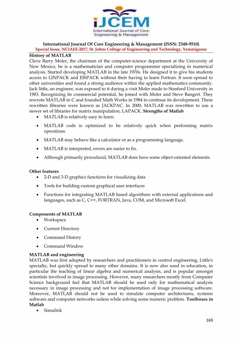
History of MATLAB Cleve Barry Moler, the chairman of the computer-science department at the University of New Mexico, he is a mathematician and computer programmer specializing in numerical analysis. Started developing MATLAB in the late 1970s. He designed it to give his students access to LINPACK and EISPACK without their having to learn Fortran. It soon spread to other universities and found a strong audience within the applied mathematics community. Jack little, an engineer, was exposed to it during a visit Moler made to Stanford University in 1983. Recognizing its commercial potential, he joined with Moler and Steve Bangert. They rewrote MATLAB in C and founded Math Works in 1984 to continue its development. These rewritten libraries were known as JACKPAC. In 2000, MATLAB was rewritten to use a newer set of libraries for matrix manipulation, LAPACK. Strengths of Matlab
MATLAB is relatively easy to learn.
MATLAB code is optimized to be relatively quick when performing matrix operations.
MATLAB may behave like a calculator or as a programming language.
MATLAB is interpreted, errors are easier to fix.
Although primarily procedural, MATLAB does have some object-oriented elements.
Other features
2-D and 3-D graphics functions for visualizing data
Tools for building custom graphical user interfaces
Functions for integrating MATLAB based algorithms with external applications and languages, such as C, C++, FORTRAN, Java, COM, and Microsoft Excel.
Components of MATLAB
Workspace
Current Directory
Command History
Command Window
MATLAB and engineering MATLAB was first adopted by researchers and practitioners in control engineering, Little's specialty, but quickly spread to many other domains. It is now also used in education, in particular the teaching of linear algebra and numerical analysis, and is popular amongst scientists involved in image processing. However, many researchers mostly from Computer Science background feel that MATLAB should be used only for mathematical analysis necessary in image processing and not for implementation of image processing software. Moreover, MATLAB should not be used to simulate computer architectures, systems software and computer networks unless while solving some numeric problem. Toolboxes in Matlab
Simulink

International Journal Of Core Engineering & Management (ISSN: 2348-9510) Special Issue, NCIAEE-2017, St. Johns College of Engineering and Technology, Yemmiganur
170
Fuzzy
Genetic algorithm
Neural network
Wavelet
Simulink Introduction Simulink is a software add-on to mat lab which is a mathematical tool developed by The Math works,(http://www.mathworks.com) a company based in Natick. Mat lab is powered by extensive numerical analysis capability. Simulink is a tool used to visually program a dynamic system (those governed by Differential equations) and look at results. Any logic circuit, or control system for a dynamic system can be built by using standard building blocks available in Simulink Libraries. Various toolboxes for different techniques, such as Fuzzy Logic, Neural Networks, DSP, Statistics etc. are available with Simulink, which enhance the processing power of the tool. The main advantage is the availability of templates / building blocks, which avoid the necessity of typing code for small mathematical processes.
Concept of signal and logic flow In Simulink, data/information from various blocks are sent to another block by lines connecting the relevant blocks. Signals can be generated and fed into blocks dynamic / static).Data can be fed into functions. Data can then be dumped into sinks, which could be scopes, displays or could be saved to a file. Data can be connected from one block to another, can be branched, multiplexed etc. In simulation, data is processed and transferred only at discrete times, since all computers are discrete systems. Thus, a simulation time step (otherwise called an integration time step) is essential, and the selection of that step is determined by the fastest dynamics in the simulated system
Block description Analog filter design:
Purpose: Design and implement analog filters Library: Filtering / Filter Implementations Description: The Analog Filter Design block designs and implements a Butterworth, Chebyshev type I, Chebyshev type II, or elliptic filter in a high pass, low pass, band pass, or band stop configuration.The input must be a sample-based, continuous-time, real-valued, scalar signal. Capacitor:
Purpose: Simulate linear
International Journal Of Core Engineering & Management (ISSN: 2348-9510) Special Issue, NCIAEE-2017, St. Johns College of Engineering and Technology, Yemmiganur
171
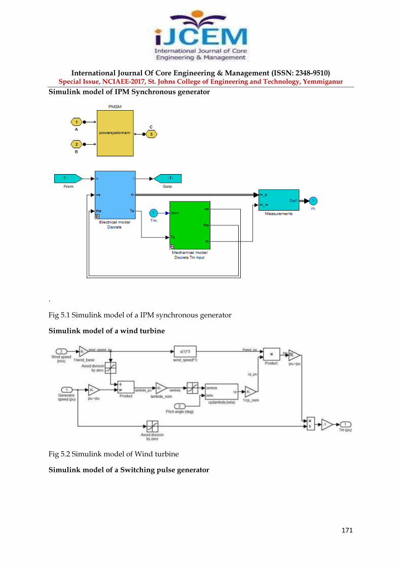
Simulink model of IPM Synchronous generator
.
Fig 5.1 Simulink model of a IPM synchronous generator
Simulink model of a wind turbine
Fig 5.2 Simulink model of Wind turbine
Simulink model of a Switching pulse generator

International Journal Of Core Engineering & Management (ISSN: 2348-9510) Special Issue, NCIAEE-2017, St. Johns College of Engineering and Technology, Yemmiganur
172
Fig 5.3 Simulink model of a switching pulse generator
Simulink Model of a Traditional Indirect vector control scheme

International Journal Of Core Engineering & Management (ISSN: 2348-9510) Special Issue, NCIAEE-2017, St. Johns College of Engineering and Technology, Yemmiganur
173
Fig 5.5 Detailed Simulink model of a traditional vector control scheme
Fig 5.6 Wind Speed curve

International Journal Of Core Engineering & Management (ISSN: 2348-9510) Special Issue, NCIAEE-2017, St. Johns College of Engineering and Technology, Yemmiganur
174
Fig 5.7 q-axis current and its reference
Fig 5.8 d-axis current and its reference
Fig 5.8 Speed reference and measured speed
Simulink model of a direct control scheme
International Journal Of Core Engineering & Management (ISSN: 2348-9510) Special Issue, NCIAEE-2017, St. Johns College of Engineering and Technology, Yemmiganur
175
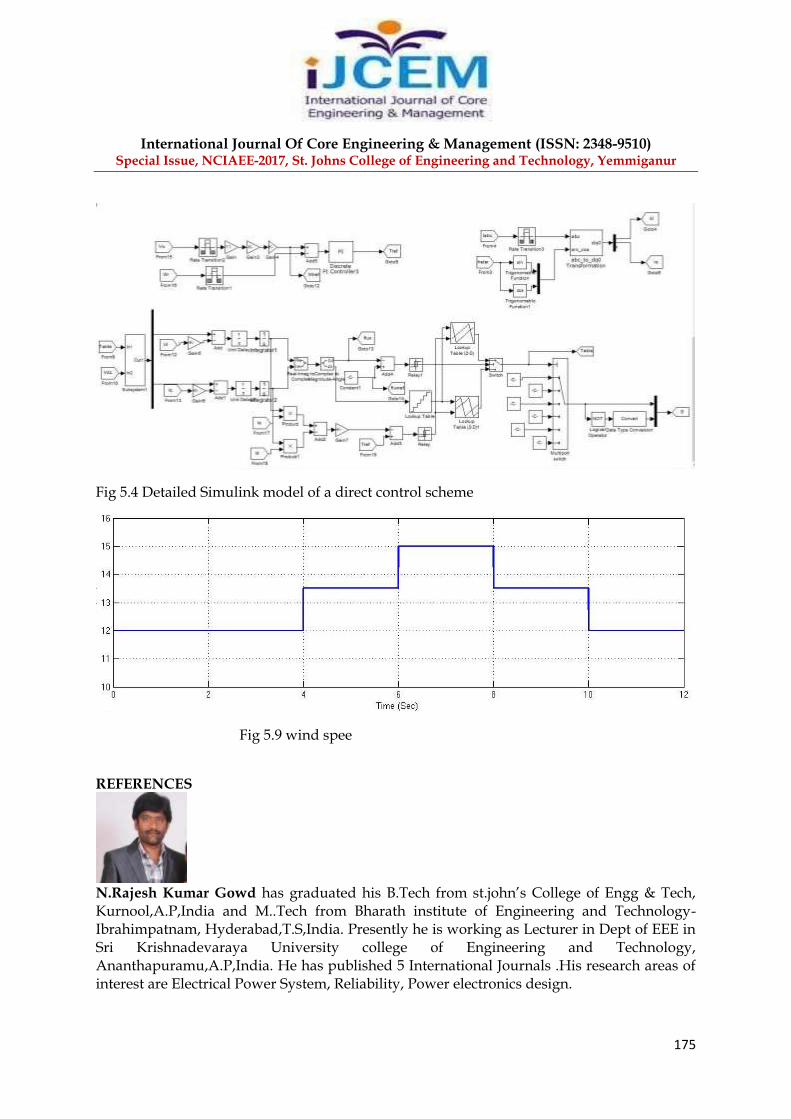
Fig 5.4 Detailed Simulink model of a direct control scheme
Fig 5.9 wind spee
REFERENCES
N.Rajesh Kumar Gowd has graduated his B.Tech from st.john’s College of Engg & Tech, Kurnool,A.P,India and M..Tech from Bharath institute of Engineering and Technology-Ibrahimpatnam, Hyderabad,T.S,India. Presently he is working as Lecturer in Dept of EEE in Sri Krishnadevaraya University college of Engineering and Technology, Ananthapuramu,A.P,India. He has published 5 International Journals .His research areas of interest are Electrical Power System, Reliability, Power electronics design.

International Journal Of Core Engineering & Management (ISSN: 2348-9510) Special Issue, NCIAEE-2017, St. Johns College of Engineering and Technology, Yemmiganur
176
J.Lakshmi Prasad has graduated his B.Tech from KSRMCE,KADAPA, A.P,India and M.Tech from JNTUCE,ANANTAPUR ,India. Presently he is working as Assistant Professor in Dept. of EEE in Anantha Lakshmi college of science and technology,affiliated jntu-ananthapuramu,A.P,India. His research areas of interest are Electrical Power System, control systems,Energy system.
G.SUBBARAO GUPTHA has graduated his B.Tech from st.Mary’s College of Engg.& Tech, Hyderabad,T.S,India and M.Tech from st.Mary’s College of Engg.& Tech, Hyderabad,T.S,India. Presently he is working as Assistant Professor in Dept. of EEE in Anantha Lakshmi college of science and technology,affiliated jntu-ananthapuramu,A.P,India. His research areas of interest are Electrical Power System, control systems.
[1] S. Müller, M. Deicke, and R. W. D. De Doncker,“Doubly fed induction generator system for wind turbines,”IEEE Ind. Appl. Mag., vol. 8, no. 3, pp. 26–33, May 2002. [2] J. Hu, H. Nian, H. Xu, and Y.He,“Dynamic modeling and improved control of DFIG under distorted grid voltage conditions,”IEEE Trans. Energy Convers., vol. 26, no. 1, pp. 163–175, Mar. 2011. [3] M. Mohseni, M. S. M. Islam, and M. A. Masoum,“Enhanced hysteresisbased current regulators in vector control of DFIG wind turbine,”IEEE Trans. Power Electron., vol. 26, no. 1, pp. 223–234, Jan. 2011. [4] H. Polinder, F. F. A. Van der Pijl, G. J. de Vilder, and P. J. Tavner, “Comparison of direct-drive and geared generator concepts for wind turbines,” IEEE Trans. Energy Convers., vol. 3, no. 21, pp. 725–733, Sep. 2006. [5] T. F. Chan and L. L. Lai, “Permanent-magnet machines for distributed generation: A review,”IEEE Power Engg. Annual Meeting, Tampa, FL, USA, Jun. 24–28, 2007, pp. 1–6 [6] M. E. Haque, M. Negnevitsky, and K. M. Muttaqi,“A novel control strategy for a variable-speed wind turbine with a permanent-magnet synchronous generator,” IEEE Trans. Ind. Appl., vol. 46, no. 1, pp. 331–339, Jan./Feb. 2010. [7] R. Esmali and L. Xu,“Sensorless control of permanent magnet generator in wind turbine application,”IEEE Industry Applications Society Annual Meeting, Tampa, FL, USA, Oct. 8–12, 2006, pp. 2070–2075. [8] M. Chinchilla, S. Arnaltes, and J. C. Burgos,“Control of permanent-magnet generators applied to variable-speed wind-energy systems connected to the grid,”IEEE Trans. Energy Convers., vol. 21, no. 1, pp. 130–135, Mar. 2006.