Embed Size (px)
Citation preview

Advanced Computing Concepts Slide Set 1-3. Finite state models of Reactive Systems. Theodore Norvell
Reactive Systems
A finite state machine is similar to a finite state recognizer, but
may include output as well as input.
Finite State Machine
Consider a machine A = (S,O,Q, qstart, T ) where
• S is an input alphabet
• O is an output alphabet
• Q is a finite set of states
• qstart is the initial state
• T is a set of transitions fromQ×(S1 ∪ {ε}
)×(O1 ∪ {ε}
)×
Q
We assume S ∩ O = ∅.
Such a machine defines a set of strings L(A) ⊆ (S ∪O)∗:
If there is a path from qstart to some state in Q and
• s is the catenation of input and output labels along that path,
• then s ∈ L(A).
Application to digital circuits
If the machine is free of εs on both inputs or outputs, then each
input is followed by a corresponding output. This gives a good
model for synchronous digital systems.
Example: Let S = {00, 01, 10, 11} and O = {0, 1}
March 2, 2010 1

Advanced Computing Concepts Slide Set 1-3. Finite state models of Reactive Systems. Theodore Norvell
0 111 / 0
00 / 1
01 / 1
00 / 0
01 / 0
11 / 1
10 / 1 10 / 0
Now we have a serial adder. If we feed in two numbers,
least-significant bit first, the machine produces the sum. E.g.
we have
[10 1 00 0 11 0 01 0 10 0 00 1 11 0 01 0 10 0 00 1
corresponding to the sum.
01010101010011001100
1000100001
March 2, 2010 2
Advanced Computing Concepts Slide Set 1-3. Finite state models of Reactive Systems. Theodore Norvell
System modelling and StateCharts
Reactive systems
Reactive systems are systems that must react to events.
• A Calculator must react to the keypresses
• A Microwave oven must react to keypresses and also to the
passage of time.
• An internet Router must react to the arrival of packets
• A synchronous hardware circuit must react to the clock
ticks.
• Most systems can be viewed as reactive.
We can specify and/or model a reactive system using state
machines.
StateCharts
StateCharts is a diagrammatic language for modelling finite
state systems.
There are various flavours of StateCharts.
I’ll be using UML StateCharts.
Transitions
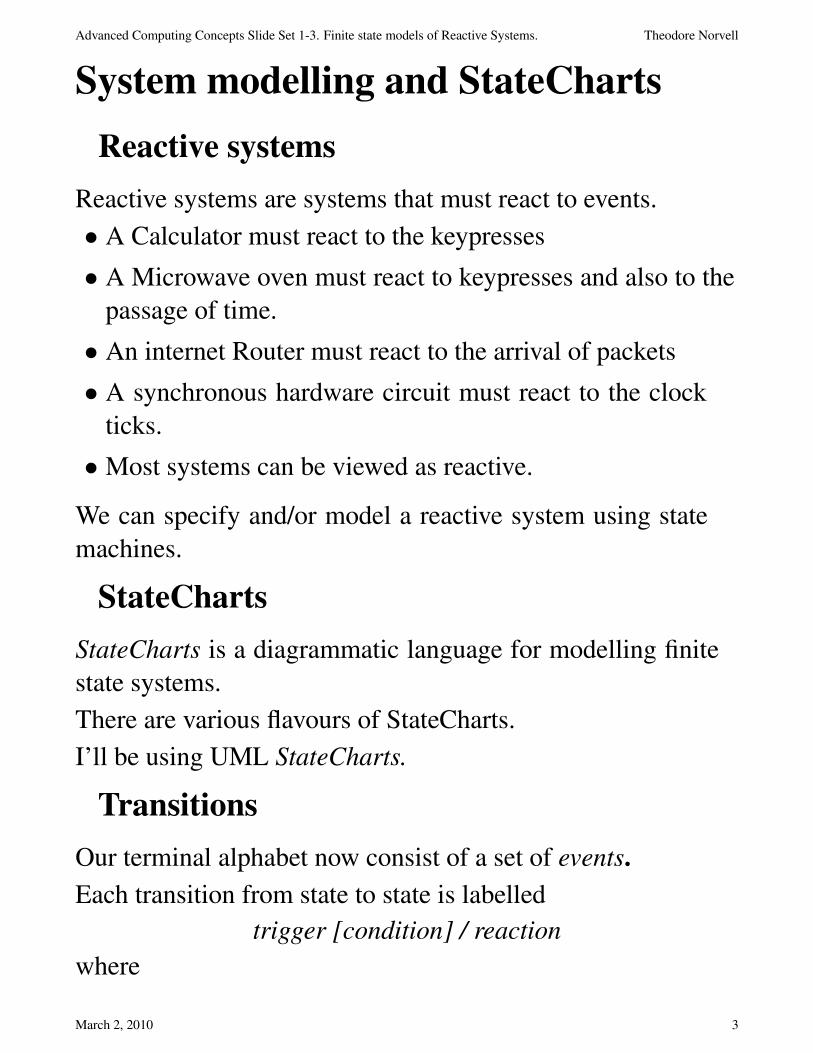
Our terminal alphabet now consist of a set of events.
Each transition from state to state is labelled
trigger [condition] / reaction
where
March 2, 2010 3
Advanced Computing Concepts Slide Set 1-3. Finite state models of Reactive Systems. Theodore Norvell
• the trigger is an event that triggers the transition
• the condition is a boolean expression
• the reaction is either
∗ an event that is generated,
∗ or a change to the system’s state variables
Example: A Clap-light.
Off
Dim
Bright
Clap / level := 60W Clap / level := 120 W
Clap / level := 0 W
/ level := 0 W
Data Dictionary:
Entity Kind Description
Clap Event Occurs when
a single clapping sound is
detected.
level System variable The amount of power sent
to the lights.
March 2, 2010 4

Advanced Computing Concepts Slide Set 1-3. Finite state models of Reactive Systems. Theodore Norvell
Here there are 3 states. One event: Clap and reactions that
change the system’s state variable level.
If the system is in state Off and a Clap event occurs, then
• immediately and simultaneously
• level is set to 60W and the system state changes of Dim.
Transitions in detail
Transitions are labeled as:
(trigger)? ([condition])?( / reaction )?
• If the trigger event is omitted,
∗ the transition is taken as soon as the condition is true.
• If the condition part is omitted,
∗ the condition is true
• If the reaction is omitted
∗ there is no reaction, only a state change.
Conditions
Conditions can be used to inhibit transitions:
Operating ShutdownRadiationReport(r) [ r > 100 ]
Notice the event is parameterized.
March 2, 2010 5
Advanced Computing Concepts Slide Set 1-3. Finite state models of Reactive Systems. Theodore Norvell
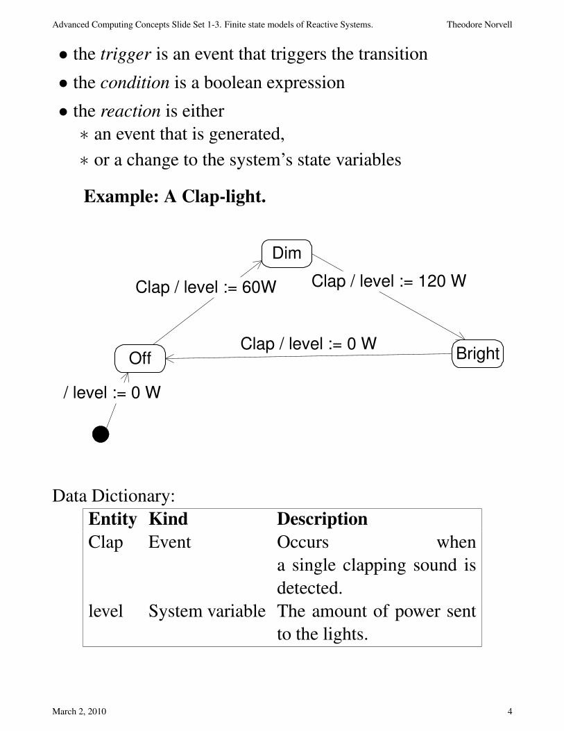
Conditions can also be used to choose between transitions:
HoldCourse
WheelToStarboard
WheelToPort
CourseErrorReport(e) [ e < -5deg ]
CourseErrorReport(e) [ e > +5deg ]
We could also illustrate this as: (The diamond is not a state.)
HoldCourse
WheelToPort
WheelToStarboard
CourseErrorReport(e)
[ e < -5 deg ]
[ e > + 5 deg ]
Time
It is important to realize:
March 2, 2010 6

Advanced Computing Concepts Slide Set 1-3. Finite state models of Reactive Systems. Theodore Norvell
Time passes in the states.
Thus transitions are essentially instantaneous.
What if you want a delay?
For real-time systems, the passage of time is an important kind
of event.
• after: 1 second is an event that happens 1 second after the
source state was entered.
• when( 11:59 AM ) is an event that takes place at 11:59
AM.
Right
Ready
Left
Lockout
LeftTouch / redLight := on RightTouch / greenLight := on
after: 45 ms +- 5 ms after: 45 ms +- 5 ms
RightTouch / greenLight:= on LeftTouch / redLight := on
Hierarchy
Time passes within states.
During that time the system need not be idle.
March 2, 2010 7
Advanced Computing Concepts Slide Set 1-3. Finite state models of Reactive Systems. Theodore Norvell
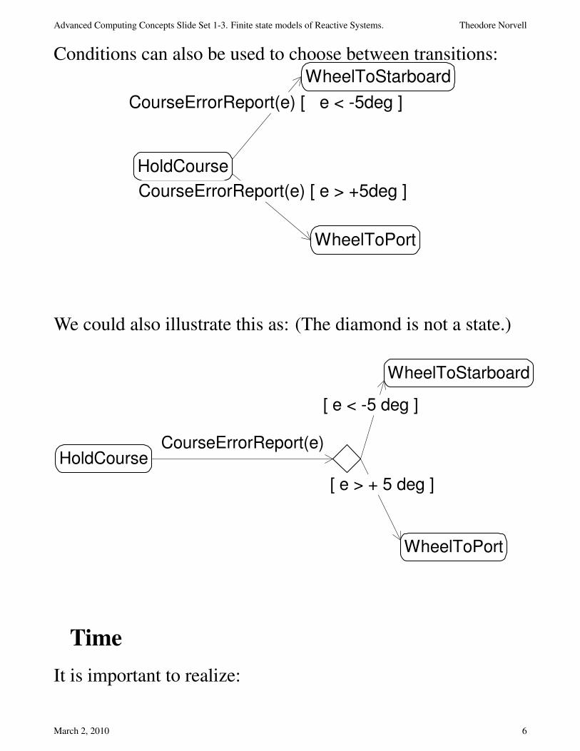
We can divide states into substates
Half
Impulse
ImpulseWarp
Full
Impulse
Warp 1
Warp 5
Warp 10
up down
updown
updown
ToWarp
LeaveWarp
When this system is in state Impulse it will be in exactly one
of the substates Half Impulse or Full Impulse.
When it is in state Warp it will be in exactly one of its 3
substates.
At system start the system is in both states Impulse and Half
Impulse.
If the system is in state Impulse and a ToWarp event happens,
the system will transition to both states Warp and Warp 1.
States like Impulse and Warp are called “or” states, since
when the system is in an “or” state, it is also in exactly one of
the “or” state’s substates.
States with no substates are called “basic” states.
The term “state” is being abused here since a system should
really be in exactly one state at a time. The set of StateChart
states the system is in constitutes its “true” state.
March 2, 2010 8

Advanced Computing Concepts Slide Set 1-3. Finite state models of Reactive Systems. Theodore Norvell
Some people prefer to call “or states” “modes”.
Concurrency.
When the system is in an “and” state, it is also in all of the
“and” state’s substates.
The substates of an “and” state are always “or” states.
An example (transitions omitted)
Wheels
LFreeRFree
LLockedRLocked
LForward RForwardLReverse RReverse
Left Right
Wheels is an “and” state.
Its substates are Left and Right which are both “or” states.
The system could be in states Wheels, Left, Right, LReverse,
and RLocked all at the same time.
March 2, 2010 9
Advanced Computing Concepts Slide Set 1-3. Finite state models of Reactive Systems. Theodore Norvell
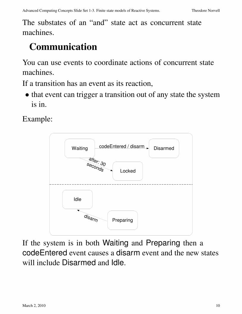
The substates of an “and” state act as concurrent state
machines.
Communication
You can use events to coordinate actions of concurrent state
machines.
If a transition has an event as its reaction,
• that event can trigger a transition out of any state the system
is in.
Example:
Waiting Disarmed
Locked
after: 30seconds
codeEntered / disarm
Idle
Preparingdisarm
If the system is in both Waiting and Preparing then a
codeEntered event causes a disarm event and the new states
will include Disarmed and Idle.
March 2, 2010 10
Advanced Computing Concepts Slide Set 1-3. Finite state models of Reactive Systems. Theodore Norvell
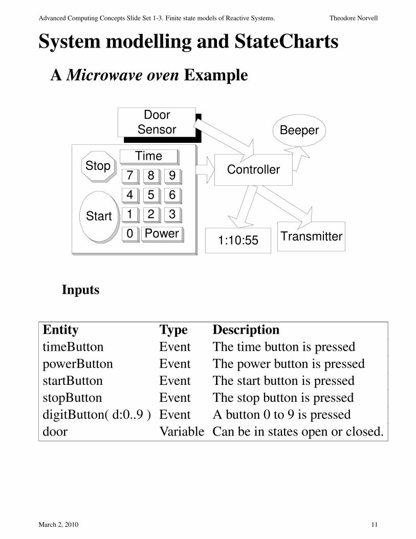
System modelling and StateCharts
A Microwave oven Example
Transmitter0
1 2 3
4 5 6
7 8 9
Time
Power
Start
Stop Controller
1:10:55
DoorSensor Beeper
Inputs
Entity Type Description
timeButton Event The time button is pressed
powerButton Event The power button is pressed
startButton Event The start button is pressed
stopButton Event The stop button is pressed
digitButton( d:0..9 ) Event A button 0 to 9 is pressed
door Variable Can be in states open or closed.
March 2, 2010 11
Advanced Computing Concepts Slide Set 1-3. Finite state models of Reactive Systems. Theodore Norvell
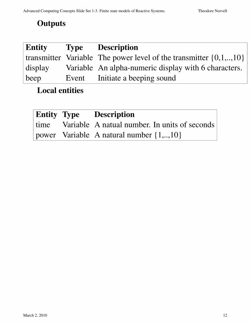
Outputs
Entity Type Description
transmitter Variable The power level of the transmitter {0,1,..,10}
display Variable An alpha-numeric display with 6 characters.
beep Event Initiate a beeping sound
Local entities
Entity Type Description
time Variable A natual number. In units of seconds
power Variable A natural number {1,..,10}
March 2, 2010 12
Advanced Computing Concepts Slide Set 1-3. Finite state models of Reactive Systems. Theodore Norvell
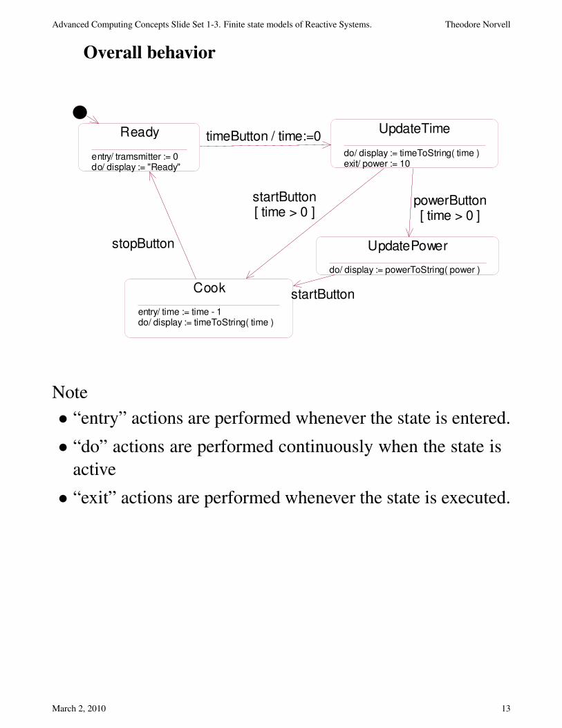
Overall behavior
Ready
entry/ tramsmitter := 0do/ display := "Ready"
UpdateTime
do/ display := timeToString( time )exit/ power := 10
Cook
entry/ time := time - 1do/ display := timeToString( time )
UpdatePower
do/ display := powerToString( power )
timeButton / time:=0
startButton
stopButton
powerButton[ time > 0 ]
startButton[ time > 0 ]
Note
• “entry” actions are performed whenever the state is entered.
• “do” actions are performed continuously when the state is
active
• “exit” actions are performed whenever the state is executed.
March 2, 2010 13
Advanced Computing Concepts Slide Set 1-3. Finite state models of Reactive Systems. Theodore Norvell
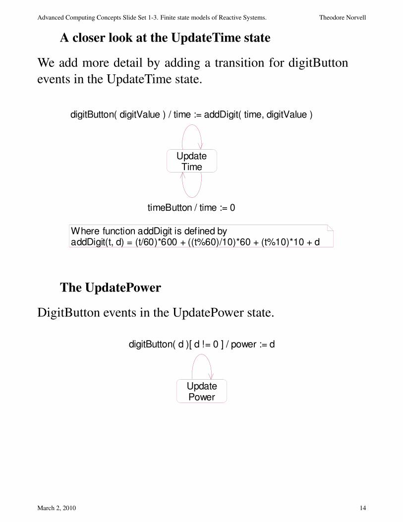
A closer look at the UpdateTime state
We add more detail by adding a transition for digitButton
events in the UpdateTime state.
UpdateTime
digitButton( digitValue ) / time := addDigit( time, digitValue )
Where function addDigit is defined byaddDigit(t, d) = (t/60)*600 + ((t%60)/10)*60 + (t%10)*10 + d
timeButton / time := 0
The UpdatePower
DigitButton events in the UpdatePower state.
UpdatePower
digitButton( d )[ d != 0 ] / power := d
March 2, 2010 14
Advanced Computing Concepts Slide Set 1-3. Finite state models of Reactive Systems. Theodore Norvell
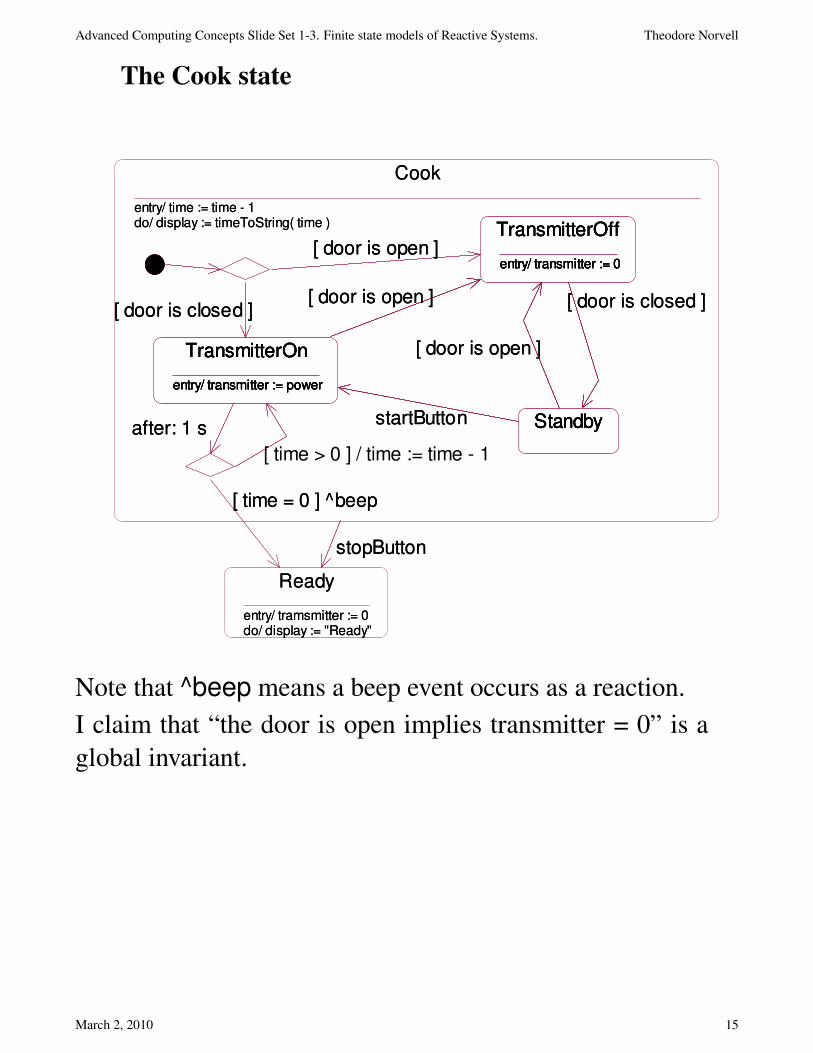
The Cook state
Cook
entry/ time := time - 1do/ display := timeToString( time )
Standby
TransmitterOff
entry/ transmitter := 0
TransmitterOn
entry/ transmitter := power
Ready
entry/ tramsmitter := 0do/ display := "Ready"
stopButton
Standby
TransmitterOff
entry/ transmitter := 0
TransmitterOn
entry/ transmitter := power
[ door is open ]
[ door is open ]
startButton
[ door is closed ]
after: 1 s
[ door is closed ]
[ door is open ]
[ time > 0 ] / time := time - 1
[ time = 0 ] ^beep
Cook
entry/ time := time - 1do/ display := timeToString( time )
Standby
TransmitterOff
entry/ transmitter := 0
TransmitterOn
entry/ transmitter := power
Ready
entry/ tramsmitter := 0do/ display := "Ready"
Standby
TransmitterOff
entry/ transmitter := 0
TransmitterOn
entry/ transmitter := power
stopButton
[ door is open ]
[ door is closed ]
startButton
[ door is open ]
after: 1 s
[ time = 0 ] ^beep
[ door is closed ]
[ door is open ]
Note that ^beep means a beep event occurs as a reaction.
I claim that “the door is open implies transmitter = 0” is a
global invariant.
March 2, 2010 15
Advanced Computing Concepts Slide Set 1-3. Finite state models of Reactive Systems. Theodore Norvell
Using StateCharts to model software
classes
Reactive Systems and objects have a lot in common.
• Reactive systems react to events
• Classes react to method invocations.
• Reactive systems have states on which behaviour depends
• Classes have states on which behaviour depends.
Input Events:
• Method calls to this object
Input variables:
• Variables and objects known to the class
Output events
• Calls to objects known to the class
Output variables
• Variables and objects changeable by this object.
March 2, 2010 16
Advanced Computing Concepts Slide Set 1-3. Finite state models of Reactive Systems. Theodore Norvell
Relationship to other UML diagrams:
• Class diagrams describe the “static” relationships between
classes.
• Sequence and collaboration diagrams show examples of
behaviour.
• StateCharts describe behaviour.
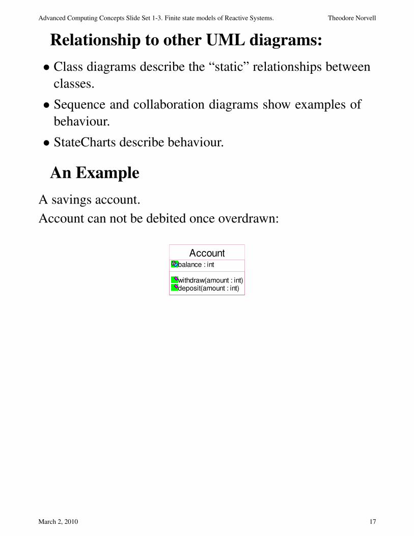
An Example
A savings account.
Account can not be debited once overdrawn:
Accountbalance : int
withdraw(amount : int)deposit(amount : int)
March 2, 2010 17
Advanced Computing Concepts Slide Set 1-3. Finite state models of Reactive Systems. Theodore Norvell
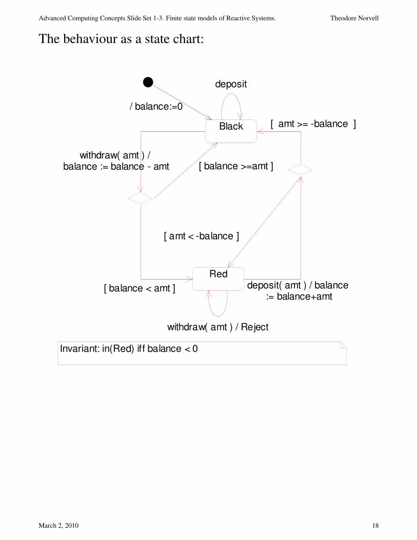
The behaviour as a state chart:
Black
Red
withdraw( amt ) / Reject
deposit
deposit( amt ) / balance := balance+amt
[ balance < amt ]
[ balance >=amt ]withdraw( amt ) /
balance := balance - amt
[ amt < -balance ]
[ amt >= -balance ]
Invariant: in(Red) iff balance < 0
/ balance:=0
March 2, 2010 18
Advanced Computing Concepts Slide Set 1-3. Finite state models of Reactive Systems. Theodore Norvell
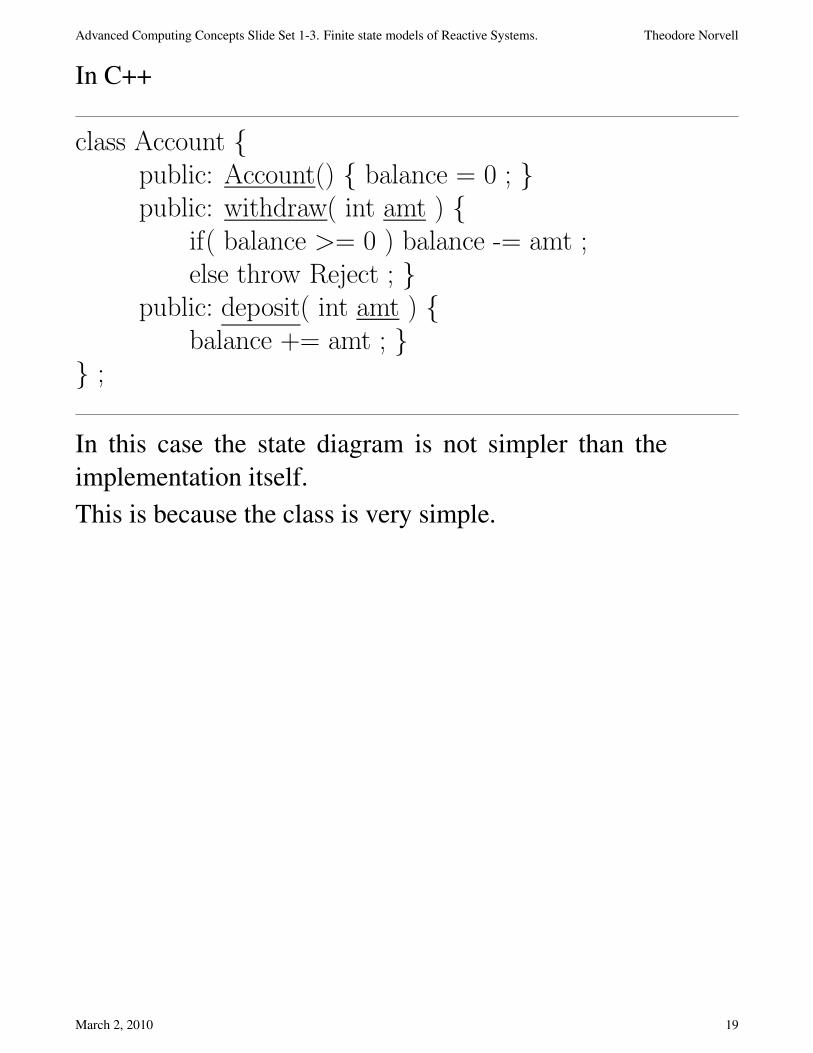
In C++
class Account {public: Account() { balance = 0 ; }public: withdraw( int amt ) {
if( balance >= 0 ) balance -= amt ;else throw Reject ; }
public: deposit( int amt ) {balance += amt ; }
} ;
In this case the state diagram is not simpler than the
implementation itself.
This is because the class is very simple.
March 2, 2010 19

Advanced Computing Concepts Slide Set 1-3. Finite state models of Reactive Systems. Theodore Norvell
Another example:
This class represents a source of network messages.
• It must be initialized before being used and should be
shutdown after use.
• It observes a network channel. Thus the network channel is
an input variable.
• The client of this class may use it to get lines.
Client_network_layer
init()shutdown()get_line(str : StringBuffer) : boolean
networkConnection
0..1
0..1
0..1
0..1
March 2, 2010 20
Advanced Computing Concepts Slide Set 1-3. Finite state models of Reactive Systems. Theodore Norvell
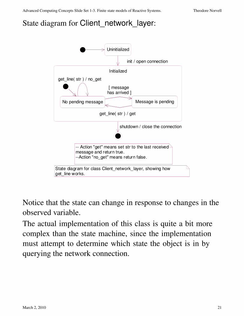
State diagram for Client_network_layer:
Initialized
No pending message Message is pendingNo pending message Message is pending
Uninitialized
init / open connection
get_line( str ) / no_get
[ message has arrived ]
get_line( str ) / get
shutdown / close the connection
-- Action "get" means set str to the last received message and return true.--Action "no_get" means return false.
State diagram for class Client_network_layer, showing how get_line works.
Notice that the state can change in response to changes in the
observed variable.
The actual implementation of this class is quite a bit more
complex than the state machine, since the implementation
must attempt to determine which state the object is in by
querying the network connection.
March 2, 2010 21
Advanced Computing Concepts Slide Set 1-3. Finite state models of Reactive Systems. Theodore Norvell
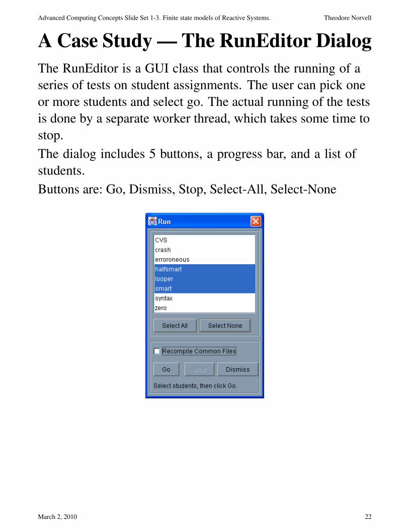
A Case Study — The RunEditor Dialog
The RunEditor is a GUI class that controls the running of a
series of tests on student assignments. The user can pick one
or more students and select go. The actual running of the tests
is done by a separate worker thread, which takes some time to
stop.
The dialog includes 5 buttons, a progress bar, and a list of
students.
Buttons are: Go, Dismiss, Stop, Select-All, Select-None
March 2, 2010 22

Advanced Computing Concepts Slide Set 1-3. Finite state models of Reactive Systems. Theodore Norvell
JDialog
RunEditor JButton
5
JProgressBar
1
JList
1
JCheckBox
1
StateChart
The class has 3 major states
• Waiting. The user: can select students from list, initiate run
(if students are selected), dismiss the dialog.
• Running. The user: can initiate a stop.
• Stop. The user must wait until the stop is complete.
Note the StateChart on the next slide is a simplification as
it omits the state of the selection buttons, the list, and the
progress bar, as well as state inherited from JDialog.
Note that the state of the buttons is properly a part of the state
of the RunEditor. This is because the relationship between
these classes is one of Aggregation.
March 2, 2010 23
Advanced Computing Concepts Slide Set 1-3. Finite state models of Reactive Systems. Theodore Norvell
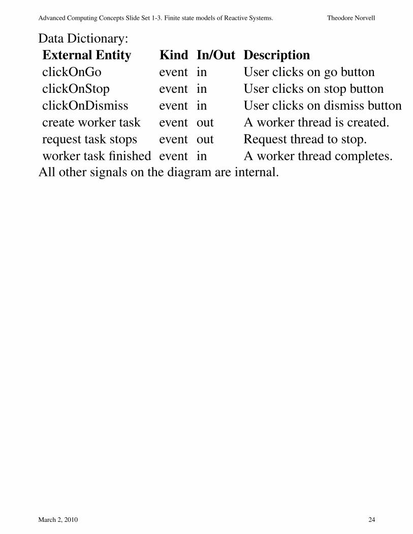
Data Dictionary:
External Entity Kind In/Out Description
clickOnGo event in User clicks on go button
clickOnStop event in User clicks on stop button
clickOnDismiss event in User clicks on dismiss button
create worker task event out A worker thread is created.
request task stops event out Request thread to stop.
worker task finished event in A worker thread completes.
All other signals on the diagram are internal.
March 2, 2010 24
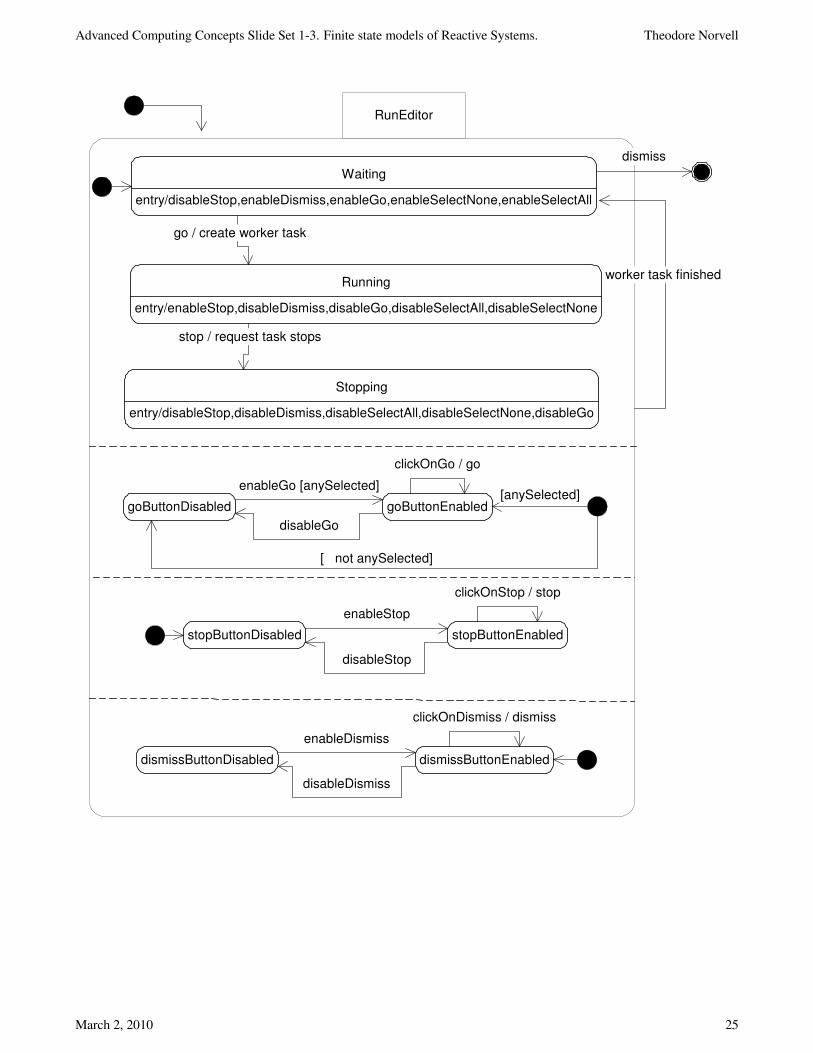
Advanced Computing Concepts Slide Set 1-3. Finite state models of Reactive Systems. Theodore Norvell
entry/disableStop,enableDismiss,enableGo,enableSelectNone,enableSelectAll
Waiting
entry/enableStop,disableDismiss,disableGo,disableSelectAll,disableSelectNone
Running
entry/disableStop,disableDismiss,disableSelectAll,disableSelectNone,disableGo
Stopping
go / create worker task
stop / request task stops
worker task finished
goButtonDisabled goButtonEnabled
enableGo [anySelected]
disableGo
clickOnGo / go
stopButtonDisabled stopButtonEnabled
enableStop
disableStop
clickOnStop / stop
dismiss
dismissButtonDisabled dismissButtonEnabled
enableDismiss
disableDismiss
clickOnDismiss / dismiss
[anySelected]
RunEditor
[ not anySelected]
March 2, 2010 25
Advanced Computing Concepts Slide Set 1-3. Finite state models of Reactive Systems. Theodore Norvell
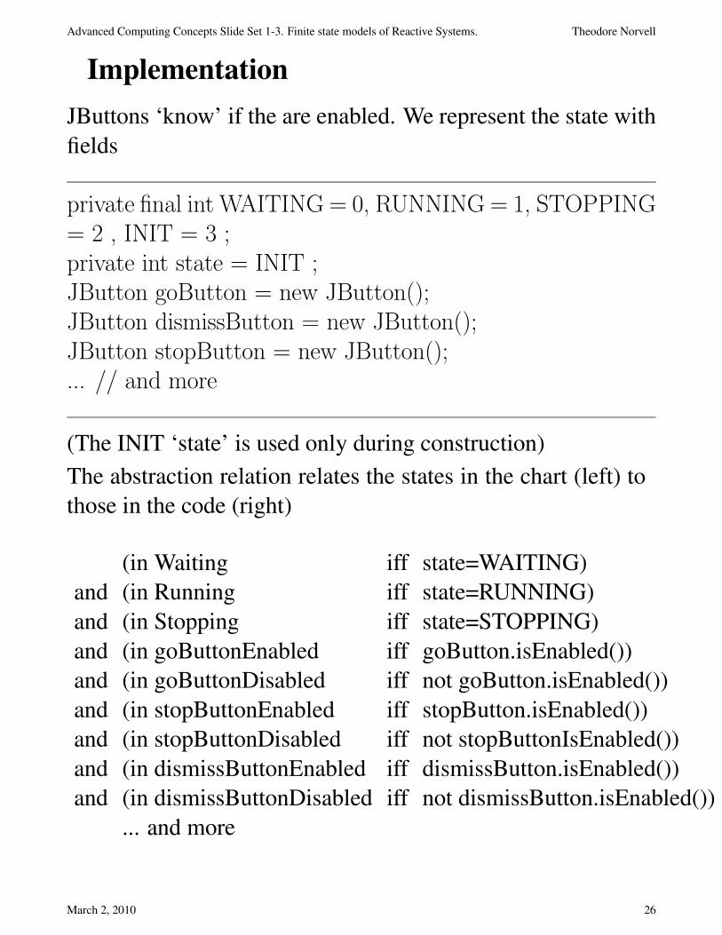
Implementation
JButtons ‘know’ if the are enabled. We represent the state with
fields
private final int WAITING = 0, RUNNING = 1, STOPPING= 2 , INIT = 3 ;private int state = INIT ;JButton goButton = new JButton();JButton dismissButton = new JButton();JButton stopButton = new JButton();... // and more
(The INIT ‘state’ is used only during construction)
The abstraction relation relates the states in the chart (left) to
those in the code (right)
(in Waiting iff state=WAITING)
and (in Running iff state=RUNNING)
and (in Stopping iff state=STOPPING)
and (in goButtonEnabled iff goButton.isEnabled())
and (in goButtonDisabled iff not goButton.isEnabled())
and (in stopButtonEnabled iff stopButton.isEnabled())
and (in stopButtonDisabled iff not stopButtonIsEnabled())
and (in dismissButtonEnabled iff dismissButton.isEnabled())
and (in dismissButtonDisabled iff not dismissButton.isEnabled())
... and more
March 2, 2010 26

Advanced Computing Concepts Slide Set 1-3. Finite state models of Reactive Systems. Theodore Norvell
Implementation continued
It is useful to centralize the state switching code in one
subroutine
private void changeState( int newState ) {if( newState == WAITING ) {
if( studentList.getModel().getSize() != 0 )listLabel.setText(”Select students...”);
else listLabel.setText(”No students ...”) ;removeProgressBar() ;goButton.getModel().setEnabled(anySlctd() );dismissButton.getModel().setEnabled( true );stopButton.getModel().setEnabled( false );allButton.getModel().setEnabled( true );noneButton.getModel().setEnabled( true ); }
else if( newState == RUNNING ) {... code to enter Running state... }
else if( newState == STOPPING ) {...code to enter Stopping State... }
state = newState ;}
March 2, 2010 27