Embed Size (px)
Citation preview

Principle Investigator: John MeyerPresenter: Heidi Crandall
Halla Visteon Climate Control June 10, 2015
Advanced Climate Systems for EV Extended Range
(ACSforEVER)
Project ID # VSS135
This presentation does not contain any proprietary, confidential or otherwise restricted information

Overview
Project Start: Oct. 2013Project End: Jan 2017Percent Complete – 40%
• EV market adoption • Minimize climate system impact on
vehicle energy storage system• Extended range across broad
selection of ambient environments
Total project funding: $4.68M- DOE share $2.34M
- Contractor share $2.34M
Funding received in FY14: $901k
Funding for FY15: $1.7M
Timeline
Budget
Barriers/Challenges
• Hyundai America Technical Center- Vehicle Integration and Testing
• National Renewable Energy Laboratory- CAE Modeling and Test Support
• Halla Visteon Climate Control- Project Lead
Project Partners
2

Relevance - DOE Support
Vehicle Technologies Program Goals:• Develop more energy-efficient and environmentally friendly technologies…and
enable America to use less petroleum and reduce GHG (greenhouse gases).• Further development and validation of models and simulation tools to predict
the performance of advanced conventional and electric-drive vehicle systems.• Support EV Everywhere Grand Challenge through DE-FOA-000793 Area Of
Interest 11 - Climate Auxiliary Load Reduction focus areas:
- Advanced HVAC Technologies to achieve passenger comfort with reduced auxiliary loads
- Cabin Pre-conditioning while connected to the grid to reduce the amount of energy needed from the battery upon initial vehicle operation to either pull-down (hot conditions) or raise (cold conditions) the temperature in the cabin
- Energy Load Reduction and Energy Management to reduce thermal loads that the systems must address
3

Relevance – Project Objectives
ACSforEVER project support of DOE VTP goals through:- Overall objectives:
• Extend electric vehicle range – Reduce climate energy usage from vehicle ESS– Development and validation of modeling tools– Technical areas of focus:
» Cabin pre-conditioning » Thermal energy storage » Refrigerant system efficiencies» Perceived comfort control strategy & zonal
• Maintain occupant comfort
- FY14 objectives:• Set performance targets• Complete baseline vehicle and bench testing• Develop, correlate, & utilize modeling tools • Define system architecture
ESS = energy storage system4
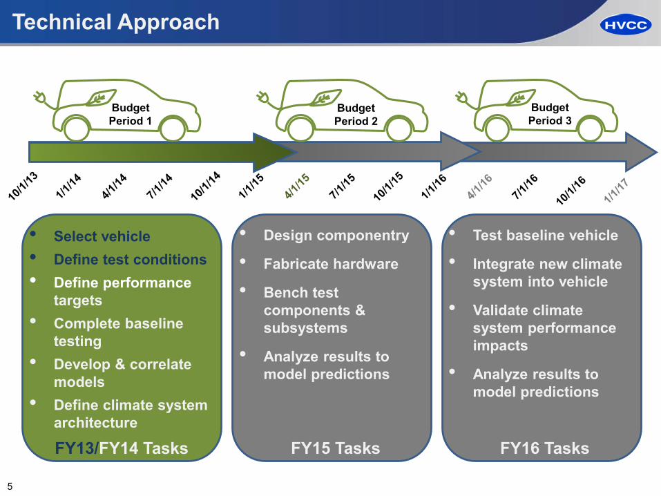
Technical Approach
• Select vehicle • Define test conditions• Define performance
targets• Complete baseline
testing• Develop & correlate
models• Define climate system
architecture
• Design componentry
• Fabricate hardware
• Bench test components & subsystems
• Analyze results to model predictions
• Test baseline vehicle
• Integrate new climate system into vehicle
• Validate climate system performance impacts
• Analyze results to model predictions
Budget Period 1
Budget Period 2
Budget Period 3
FY13/FY14 Tasks FY15 Tasks FY16 Tasks
5

Milestones
Budget Period 1: Subsystem Design and Specification Development Complete
Budget Period 2: Design, Fabricate, and Validate
Budget Period 3: Integration and Vehicle Validation
Month-Year Milestone Type Description
Jun-2016 Vehicle Integration Technical All subsystems integrated into vehicle and ready for testing
Dec-2016 Vehicle Demonstration Technical Demonstration vehicle testing complete
Month/Year Milestone Type Description
Sep-2014 Baseline Vehicle Testing Technical Completion of baseline vehicle testing in a wind tunnel.
Mar-2015 System Architecture Complete Go/No Go
Completion of system architecture design for each subsystem to verify established system requirements are met
Month/Year Milestone Type Description
Mar-2016 Bench Testing Go/No Go Subsystems testing to verify established system requirements are met
6

Accomplishments - FY13
Selected Vehicle:2015MY Kia Soul EV with heat pump and positive temperature coefficient (PTC) heater
Project test conditions
KeyProject drive cycle
Technical accomplishments recap from FY13
Photo courtesy of Tony Vespa, HATCI
7
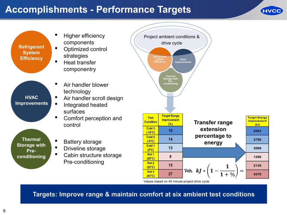
Accomplishments - Performance Targets
Transfer range extension
percentage to energy
Project ambient conditions & drive cycle
Thermal Storage with
Pre-conditioning
HVAC Improvements
Refrigerant System
Efficiency
Refrigerant System
Efficiency
HVAC Improvements
Thermal Storage with
Pre-conditioning
• Higher efficiency components
• Optimized control strategies
• Heat transfer componentry
• Air handler blower technology
• Air handler scroll design• Integrated heated
surfaces• Comfort perception and
control
• Battery storage• Driveline storage• Cabin structure storage
Pre-conditioning
Targets: Improve range & maintain comfort at six ambient test conditions
𝒌𝒌𝒌𝒌 ∗ 𝟏𝟏 −𝟏𝟏
𝟏𝟏 + % =
Values based on 40 minute project drive cycle
Target Energy Improvement
(kJ)
2099
1286
2130
4376
2503
2706
Veh.
Target Range Improvement
(%)
14
13
Cold 2 (-5°C)Cold 1 (5°C)
9
15
Test Condition
10Cold 3(-18°C)
Hot 1 (28°C)Hot 2(32°C)Hot 3(43°C) 27
8

Accomplishments - Vehicle Level Evaluations
Jan2014Cold Weather
Testing
• Took place in International Falls, MN• HATCI “sign-off” trip• Both PTC and HP vehicles tested• Benefit: Cold weather vehicle exposure, gain familiarity with road
evaluation test methods and team building
May2014Wind Tunnel
Testing
• Took place in Farmington Hills, MI• Baseline HP Kia Soul vehicle tested• 5 of 6 test conditions tested: -18°C, -5°C, +5°C, 28°C and 43°C• Benefit: Data utilized for model correlations
Jun2014Hot Weather
Testing
• Took place in Death Valley, CA• HATCI “sign-off” trip• Both PTC and HP vehicles tested• Benefit: Hot weather vehicle exposure and gain familiarity with
road evaluation test methods
Feb2015Cold Weather
Testing
• Took place in Ann Arbor, MI• Kia HP baseline vehicle and second modification vehicle tested• Benefit: Early evaluations of various improvement concepts
9

Accomplishments –Vehicle Wind Tunnel Evaluations
Overconsumption is a large energy savings opportunity
Steady state power used to maintain a comfortable cabin
5000 W needed to propel the car
Overconsumptionadditional climate power used to achieve a comfortable cabin
Vehicle Power Usage at 43°C
10

Accomplishments – Feb 2015 Vehicle Road Evaluations (-18°C)
Directional improvement seen for driveline thermal storage
11

Accomplishments – System Bench Testing
A/CTesting
• Kia system built and fully instrumented in system test room• 17 AC conditions evaluated• 25°C to 60°C ambient temperatures• 2,000 rpm to 7,000 rpm compressor speeds
HP Testing
• Completed system room modifications to run heat pump conditions
• 33+ HP conditions evaluated• 15°C to -10°C ambient temperatures• 1,500 rpm to 5,000 rpm compressor speeds
Data Collected
• Utilized for model correlations• Characterize compressor• System understanding• Examine effect of warming glycol
12
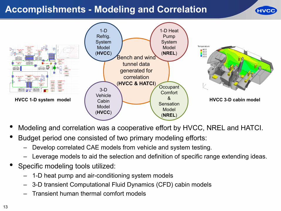
Accomplishments - Modeling and Correlation
• Modeling and correlation was a cooperative effort by HVCC, NREL and HATCI.• Budget period one consisted of two primary modeling efforts:
– Develop correlated CAE models from vehicle and system testing.– Leverage models to aid the selection and definition of specific range extending ideas.
• Specific modeling tools utilized:– 1-D heat pump and air-conditioning system models– 3-D transient Computational Fluid Dynamics (CFD) cabin models– Transient human thermal comfort models
Bench and wind tunnel data
generated for correlation
(HVCC & HATCI)
1-D Refrig. System Model
(HVCC)
3-D Vehicle Cabin Model
(HVCC)
Occupant Comfort
& Sensation
Model(NREL)
1-D Heat Pump
System Model
(NREL)
HVCC 1-D system model HVCC 3-D cabin model
13

Accomplishments – Thermal System Modeling
14
•! 1-D thermal system models –! Both HVCC and NREL have developed 1-D system models –! HVCC is focusing on AC operation, NREL on heat pump
Thermal Model Development and Correlation
Modeling vs. data. Ph diagram for an operating condition
NREL HVCC
1-D A/C thermal model correlation

Accomplishments – Cabin & Comfort Modeling
• A 3-D cabin model was built and successfullycorrelated to wind tunnel test data (5 cases).
• Mannequins were added to the cabin model inorder to predict human thermal comfort.
• Results were used to aid the selection of someof the range extension ideas in FY14.
• Models will be used in FY15 for the design andoptimization of the ideas.
Model Development and Correlation
-5˚C Vehicle Warm Up
-5˚C Occupant Thermal Sensation
-5˚C Average Interior Temperature
-5˚C Occupant Thermal Comfort
15

Accomplishments - Improved Refrigerant Loop Architecture
• Replace TXV with EXV• Add high-pressure chiller• Remove “dehumidification” line and 2-
way valve• For dehumidification, flow goes through
both 2-way and AC EXV• Replace 3-way valve before
chiller/evaporator with 2-way valve asshown
• Improve heat exchanger efficiency(condenser, evaporator, internal heatexchanger)
LP Chiller
HP Chiller
Evaporator
Outside Condenser
Accum.
Inside Condenser AC EXV
2-way Valve
OT & 2-way Valve
3-way Valve
T, P
Compressor
LP Chiller
Revised Refrigerant Loop
Baseline Refrigerant Loop
16

Accomplishments - Improved Coolant Loop Architecture
• Add high-pressure chiller• Add two 3-way valves• Add glycol heater• Include battery (via cold plate)
in glycol loop for thermalstorage
• Utilize insulated motor &inverter for thermal storage
Current Glycol Loop
RadiatorOBC
Reservoir
Pump
3-way Valve
3-way Valve
3-way Valve
Battery
Inverter
Motor
HP ChillerHeater
LP Chiller
From Evap
To Accum.
Revised Glycol Loop
Baseline Coolant Loop
Additional architecture features:• Enhance pre-conditioning
method
17

Progress Towards Targets
• Current architecture assessment shows range extension percentages shown while maintaining occupant comfort
• Opportunity areas include:– 5°C: Very low/no baseline PTC
power consumption » FY15 plan to evaluate potential
improvements to provide heat while keeping compressor off for more significant contribution
– 28-43°C: Using thermal storage to sub-cool refrigerant limits amount of heat transfer and therefore benefit
» Less than 1/3 of thermal storage used
» FY15 plan to evaluate potential opportunities to increase amount of heat transfer for additional benefits
de-superheatcondensesubcool
Target Range Improvement
March 2015 Assessment
(%) (%)
14
13
Cold 2 (-5°C)Cold 1 (5°C)
6
8
10
9
15
Test Condition
10Cold 3(-18°C)
Hot 1 (28°C)Hot 2(32°C)Hot 3(43°C) 27
15
11
3
18

Automotive OEM Partner Key Support:
• Vehicle Selection– Led vehicle selection task of Kia Soul BEV– Driving improvements beyond current state-of-the-
art vehicle architecture• Vehicle Testing
– Coordinates cold and hot weather testing, as well as all wind tunnel testing
– Provides instrumented vehicles to HVCC for evaluation
– Leads data analysis following test trips• Architecture Selection
– Participation in brainstorming events and down-selection
– Maintaining focus on value, not just performance• Vehicle Technology Implementation
– Integration support of vehicle technologies and instrumentation
HATCI Collaboration and Coordination
Photo courtesy of Tony Vespa, HATCI
19

NREL Collaboration and Coordination
National Laboratory Partner Key Support:
• Comfort Modeling– Comfort model creation and correlation to wind
tunnel data – Coordinated simulations for model accuracy – Comfort model assessment of heated surface
impacts to occupant comfort» Results show positive impact of both radiant and
contact heating surfaces » Results provide guidance in hardware selection
• Thermal Modeling– Creation of CoolSim thermal model in
MATLAB/Simulink– Favorable correlation of baseline A/C and heat pump
model when compared to experimental results– Heat pump model utilized in advanced system
concept evaluations including stored heat harvesting• Technology Validation
– Support and consultation during improvement verification testing
Comfort model manikin with heated door panel
Enthalpy diagram for a thermal system operating condition
20

Barriers/Key Challenges
Barriers/Challenges RoadmapTo meet thermal storage requirements, the battery pack will be included in the glycol loop
• Options being evaluated in the next phase are retrofitting the current battery and utilization of a surrogate.
Developing technologies that take advantage of thermal storage without hindering performance when no thermal storage is available
• Design considerations include evaluation of systems with and without thermal storage usage.
Because the vehicle uses very little HVAC power at +5ºC, meeting the range extension goal at this condition is challenging.
• FY15 work plan includes evaluation of identifiedimprovement ideas to provide heat while keeping the compressor off. This will yield more significant range extension at +5ºC.
At hot ambient conditions, using thermal storage to sub-cool refrigerant limits amount of heat transfer
• FY15 work plan includes assessment of improvement ideas to increase heat transfer to mitigate this challenge
The area of human thermal sensation and comfort modeling is complex and still developing. The comfort rating aspect of the tool is relatively immature at extreme ambient conditions.
• Project team leading dialogue with comfort software supplier to help guide future improvements to human thermal comfort model
• FY15 will include more in depth evaluator training
21

Future Work
• Complete vetting of engineering challenge opportunities and evolution of the system
• Specify and design heat exchangers and valves
• Design thermal storage components
• Create and execute keystone comfort control test cases
• Continue design of components
• Begin prototype build of hardware
• Specify design and control of EXV
• Bench test thermal storage components
• Build and bench test system
• Build and program test sequencer system
• Correlate models to bench testing as needed
• Refine system control
• Continue bench testing
• Complete soak room vehicle evaluations
• Define final architecture
• Refine range estimates and system cost
• Correlate results to models
2Q15 3Q15 4Q15 1Q16
FY2015 Roadmap
22

Response to Reviewer Comments
Criteria Comment Response
ApproachReviewer focused on what expected benefit is in terms of percentage improvement in driving range.
• Vehicle range extension targets have been developed and presented in this presentation
• Also included was an update on how we are progressing towards the targets and how remaining challenges are being addressed
Approach
The reviewer commented that the project did not provide specific targets that address EV viability in very cold and hot temperature operating environments that are characteristic of large portions of the U.S. market.
• The range targets established do account for the extreme and mild ambient temperatures experienced throughout the U.S.
• Additionally, the coldest condition (-18C) shows the most benefit
Collaboration
Reviewer stated that NREL should be leveraged for CFD modeling due to their experience and knowledge base in developing and validating thermal models.
• NREL has been a key contributor in comfort and thermal modeling efforts. Their experience and knowledge in these areas has and will continue to be utilized for this project
23

Summary
• Relevance: Project scope addresses VTO objectives of extending electric vehicle driving range through climate load reduction, thus aiding in market adoption
• Approach: Team is utilizing complimentary blend of modeling and testing efforts to identify and verify load reduction and comfort acceptability
• Accomplishments: Phase I architecture does extend the range of the 15MY Kia Soul EV while maintaining comfort with further improvement opportunities identified for FY15 evaluation
• Collaboration: Experienced OEM and National Laboratory partners continue to contribute key knowledge and expertise towards project success
• Future Work: FY15 roadmap paves the way through engineering challenges and tasks required to meet the project objectives
24

www.hvccglobal.com
Thank You