Embed Size (px)
Citation preview

Advanced CAD Modelling Course
(SolidWorks 2009)

Published by: The National Centre for Technology in EducationAndT4 – Technology Subjects Support Service
National Centre for Technology in Education Dublin City University GlasnevinDublin 9 Tel: +353 1 700 8200 Email: [email protected]: www.ncte.ie / www.scoilnet.ie
T4 – Technology Subjects Support Service Galway Education Centre Cluain Mhuire Wellpark GalwayEmail: [email protected]: www.t4.ie
Copyright © National Centre for Technology in Education 2009.
Permission granted to reproduce for educational use providing the source is acknowledged. Copying for any other purposes prohibited without the prior written permission of the publisher.
Please note� Screenshots used in this manual may appear different to those on computer screens
used by participants; variations in versions of the software and differing operating systems may be in use.
� Screenshots and software titles used throughout the manual are from a PC using Microsoft Windows XP©.
� Participants using other operating systems may encounter some differences in screen presentation and layout.
Throughout this module reference may be made to software titles and suppliers of Internet services. These references are made purely to illustrate or expound course content. Any such reference does not imply any endorsement by the NCTE of a product or company. The reader should be aware that typically there are many products and companies providing similar services in areas related to ICT. Participants should be as informed as possible before making decisions on purchases of ICT products or services.

Advanced CAD Modelling Course
SolidWorks 2009 3
Advanced CAD Modelling Course – SolidWorks 2009
Table�of�Contents�
Introduction ……………………………………………………………………………… 4�
Objectives ……………………………………………………………………………….. 5�
Introduction to Sheet Metal Features …………………………………………………….. 6
Base Flange Method – Magazine File…………………………………………… 7
Envelopment & Development of Surfaces………………………………………. 18
Transition Piece Development – Extraction Hood………………………………. 27
Conversion to Sheet Metal - Golf Ball Package...………………………………. 37
Creating Curved Features 2009…………………………………………………………. 43
Helical Slide Exercise ……..…………………………………………………….. 44
Projected Curve & Lofted Boss/Base – Hand Soap Bottle……………………… 50
Introduction to Curves & Splines - Countersunk Screw ………………………… 59
Modifying Curved Features -Hand soap Bottle Modifications………………….. 65
Composite Curve – Wire Clothes Hanger …………..………………………….. 70
Working with Surfaces………………………………………………………………….. 74
Plastic Medicine Spoon…………………………………………………………. 75
Intersecting Lamina………………………………………………………….….. 81
Tangent Planes…………………………………………………………………... 88
Keyboard Button…………………………..…………………………………….. 96
Baseball Cap……………………………………………………………………. 111
Creation of Photorealistic Images………………………………………………………. 124
PhotoWorks – iPhone………………………………………………………….... 125
PhotoView 360 – Skateboard………………..………………………………….. 131

Advanced CAD Modelling Course
SolidWorks 2009 4
Advanced CAD Modelling Course – SolidWorks 2009
Introduction
The revised syllabuses for Design and Communication Graphics (previously Technical Drawing) and a new subject at Leaving Certificate level, Technology, were introduced to the senior cycle curriculum in September 2007 and were examined for the first time in 2009.
A Technology Subjects Support Service (T4) was established to support schools in the implementation of the revised/new syllabuses. The support service has rolled out the intensive phase of a professional development programme for teachers that consisted of a nine day in-service programme over three years. A significant component of this professional development was focused on Computer Aided Design (CAD). Technologies and methodologies including powerful design tools such as parametric CAD are being utilised in the revised and new technology subjects and forms part of a significant assessment component in Design and Communication Graphics. Indeed, SolidWorks parametric CAD software is being used in second level schools providing the technology subjects at both senior and junior cycle. The application integrates the development of Technology and IT skills with a variety of basic and advanced features.
Despite the very successful roll-out of the T4 professional development programme a request for additional CAD and other ICT courses have been made by the teachers of the technology subjects. This request was prompted in part by the upgrade of SolidWorks 2006 to the 2009 Education Version which was made available to all schools in March 2009. In response, the NCTE in collaboration with T4 and the Education Centres Network hope to satisfy the demand by providing additional courses and opportunities for further professional development. The Advanced CAD Modelling Course (SolidWorks 2009) is complementary to the work of the T4 professional development programme and the other three CAD Modules that were developed by the NCTE in collaboration with the Technology Subjects Teacher Professional Network.
The Advanced CAD Modelling Course has been designed to allow participants to do all or some of the exercises in the four broad areas covered – Sheet Metal Features, Curves, Surfaces and Photorealistic images. It is envisaged that this course will be delivered over 15 hours (6 evenings x 2.5 hours) but the pace of progress will be determined by the skill level of the participants. Each group is recommended to discuss the course schedule with the tutor in order to reflect their unique needs, interests and ability level. Prior to commencing the Advanced CAD Modelling Course, it is assumed that participants will have completed CAD Module 2 and 3 and have developed a broad base of basic ICT skills. An opportunity will be provided for participants to share resource materials developed during the course.
While this course is limited in the range and depth of topics it can cover, the NCTE has a wider and more detailed range of courses which address other areas of ICT. Details of these courses can be found at www.ncte.ie/training or through your local education centre. A more extensive range of CAD resource that was developed during the course of the T4 professional programme is available on www.t4.ie or by contacting your local T4 Regional Development Officer.

Advanced CAD Modelling Course
SolidWorks 2009 5
Duration
15 hours
Objectives
This course aims to enable the participant to:
� Build on and reinforce the CAD skills developed to date � Explore the more advanced features and tools within SolidWorks 2009 by:
o Building sheet metal type models and creating their development by flattening the models using the Sheet Metal features
o Creating ‘Curved Features’ which explores the uses of splines, helices, and composite curves to model everyday items and geometric problems
o Using the Surface toolbar to create faces and features which may not be conveniently produced using solid modelling techniques
o Producing high quality photorealistic images using PhotoWorks and PhotoView 360 of CAD models
� Examine the application of these advanced CAD features in enhancing the teaching and learning of the core geometry and its applications

Advanced CAD Modelling Course
SolidWorks 2009 6
Introduction to Sheet Metal Features SolidWorks 2009

Advanced CAD Modelling Course
SolidWorks 2009 7
BASE FLANGE METHOD - MAGAZINE FILE.
Sheet Metal The sheet metal feature within SolidWorks enables the user to build a sheet metal model, using a variety of sheet metal features. The development of the model can be created by flattening the model as a whole or by flattening individual bends.

Advanced CAD Modelling Course
SolidWorks 2009 8
Prerequisite knowledge To complete this model you should have a working knowledge of Solidworks 2006/2009.
Focus of lesson This lesson focuses on using the base flange approach to sheet metal. Commands used include Base Flange, Edge Flange, Corners and Extruded Cut.
Getting started. New File Create a new part file.
Save File Save the file to a chosen location as Magazine File.
Getting Started In order to begin working with Sheet Metal you must first activate the sheet metal tab on the command manager.
To activate this tab, right click on thecommand manager. Choose Sheet Metalfrom the drop-down list.
The Sheet Metal tab is now active on the command manager.
Note: The Sheet Metal commands are also available from the drop down menu by selecting “Insert” and “Sheet Metal”…
Creating a sketch: How do we start to model the magazine file as a sheet metal part?
We will begin by creating a sketch to generate the base of the file.
What plane will this sketch be created on?
Because the file sits on the horizontal plane we will create a sketch on the Top Plane.
Sketch: Create a rectangular sketch on the top plane placingthe top left hand corner coincident with the origin.
Smart dimension the rectangle as shown. Height – 400mm & Width – 100mm

Advanced CAD Modelling Course
SolidWorks 2009 9
Sheet Metal Feature: To create a sheet metal feature, click the Sheet Metal tab on the Command Manager and choose Base Flange
Enter a value of 1.50mm for thickness in the Base Flange options dialog box
Click Ok
About Base Flange When a base flange feature is created SolidWorksimmediately recognises this part as a sheet metal part.
Only one base flange feature may be inserted for each sheet metal part document.
When a base flange feature is created a number of items are added to the feature manager design tree.
Sheet-Metal1: is automatically added above the Base flange feature. It holds the default sheet metal
settings such as sheet metal thickness, radius etc.
Sheet-Metal1 will remain at the top of the feature manager design tree
Sheet-Metal 1 Right click on Sheet-Metal 1 and chooseEdit Feature
The sheet metal settings may be changed here.

Advanced CAD Modelling Course
SolidWorks 2009 10
Choose OK
Flat-Pattern Feature This is added below the base flange feature. It has a couple of special properties that are not found with other features.
Unlike other features, flat-pattern will remain at the bottom of the tree. Other sheet metal features, when added, will appear overhead even though they are added after its creation. Secondly, the feature is suppressed when added to the design tree.
We will look further at this feature as we work through this exercise.
Adding the vertical faces We will create the vertical faces using Edge Flange
Edge Flange Edge flange is used to create a 90° bend to a selected edge, in the direction and distance specified, using the thickness of the part. The shape of the flange by default is rectangular. This may be edited to a custom profile also.
Adding an Edge Flange Select Edge Flange from the sheet metal toolbar.
Choose the back edge of the base flange as the edge on which you wish to create the edge flange.
Drag the edge upwards and left click to indicate directionand an initial value for length.
The default radius of 1mm is used. The gap distance is greyed out as there is only one selection.
The flange angle is set to 90°.
Enter a value of 400mm for Flange Length
Choosing material inside will ensure that the face of the edge flange, when bent, will be flush with

Advanced CAD Modelling Course
SolidWorks 2009 11
the original edge of the base flange, as indicated opposite. A preview of the proposed flange is displayed.
We wish to add further selections to the feature.
Adding further edges. Choose the edges indicated to create further edgeflanges, using the same parameters.
Enter a Gap Distance of 0.01mm. Gap distance refers to the distance between adjacent edge flanges and must be greater than 0mm.
Click OK.
Creating cut edge: In order to complete the shape of the magazine file we must cut a section from the rectangular prism which we have created.
Extruded Cut Extruded cut within Sheet Metal is used in a similar manner to the way we use it in dealing with solid models.
We will begin by creating a sketch of the profile used to create the cut on the right face of the box.
Note: the enlarged detail of the sketch shows a horizontal line coincident with the edge of the front face and the endpoint of the inclined
line on the right face
Gap Distance

Advanced CAD Modelling Course
SolidWorks 2009 12
Select Extrude Cut from the Sheet Metal tab.
The line sketch is automatically selected. From the options list deselect the Direction 2 box.
In the direction 1 box select the Through All end condition.
Select “Flip side to cut”, if necessary, to remove what is above the plane and keep what is underneath.
Choose OK
Corners Zoom into the lower right hand corner. You will notice that the corner is open.
The faces may be extended to close the corner using the Corners feature on the Sheet Metal toolbar.
Choose Corners, Closed Corner.
Select the face indicated.
Choose a gap distance of 0.5mm
Select Overlap as corner type
An overlap ratio of 1 will ensurethat the two faces overlap completely.

Advanced CAD Modelling Course
SolidWorks 2009 13
A preview will be displayed as shown opposite.
Note: The gap distance of 0.5mm can be seen clearly at this stage.
Selecting further faces Rotate the model and choose the face as indicated below.
Rotate the model and choose the corresponding faces on the opposite side.
In total you should now have 4 faces selected.
Choose OK. The corners now appear as shownbelow.

Advanced CAD Modelling Course
SolidWorks 2009 14
Adding tabs To complete the part, tabs must be added to vertical edges of the side pieces.
We will use Edge Flange to add these tabs.
Choose Edge Flange and select the internal corner of the vertical side.
Drag the corner in the direction shown and left left click to assign an initial distance.
Input the following;
Angle - 90°
Flange Length – 20mm
Flange Position –Material Inside
Edit Flange Profile Choose Front View.
Select Edit Flange Profile from the Flange Parameters
The sketch used to create the flange appears along with the profile sketch dialog box shown.
We must edit this sketch in order to edit the shape of the flange.
We are going to edit the sketch so that the top is chamfered at 45°, as shown.

Advanced CAD Modelling Course
SolidWorks 2009 15
How will we achieve this?
Editing the sketch. We must first remove the automatic relations from the line.
To delete the relation; right click on the relation icon, displayed in green when highlighted, and select delete from the dropdown list. Alternatively choose delete from the keyboard.
Removing the relations allows us to add angular dimensions to the line.
Smart Dimension Smart dimension the angle as shown. Add the length of the flange, 20mm.
The profile sketch dialog box will indicate whether the sketch may be used to create the flange or not.
Choose Finish
A preview of the customised tab is displayed.
Choose Isometric View.

Advanced CAD Modelling Course
SolidWorks 2009 16
Selecting other edges We want to add a similar tab to the other 3 internal corners.
Using rotate and zoom commands select the remaining corners, as indicated opposite.
Unfortunately, each of the sketches defining the Individual flange profiles must be edited separately.
Choose Edge 2 and select Edit Flange Profile
Edit the profile as before.
Repeat the procedure for edges 3 & 4.
Choose OK.
Flat-pattern Remember the Flat-pattern1 feature discussed earlier? It is added to the bottom of the feature manager design tree when we create a sheet metal part. As sheet metal features are added to the part it remains at the bottom. You will also notice that it is greyed out or suppressed.
Let’s see what happens when we unsuppress it!
Unsuppress Flat-pattern Right click on the feature and choose unsuppress from the pop-up toolbar
The sheet metal model flattens out into the surface development used to create it.
All of the bend lines are displayed.
Select the top face and choose Normal To

Advanced CAD Modelling Course
SolidWorks 2009 17
Complete surface development
Suppress Left click on Flat-Pattern1 and choose Suppress to return to the sheet metal
Add appearance: Add an appropriate appearance to the model.
Choose Yellow Low Gloss Plastic
Save the completed part
Lesson Complete!

Advanced CAD Modelling Course
SolidWorks 2009 18
Envelopments and Developments of Surfaces
Prerequisite knowledge: Exercise 1 - Magazine File should be completed in advance of this exercise.
Focus of lesson: To further explore the tools available within sheet metal and investigate how these tools may be used to enhance the teaching of geometry.
Commands Used: This lesson includes Sketching, Base Flange, Flatten, Extruded Cut, Fold and Unfold.
Problem: A worksheet is presented based on a hexagonal prism and irregular shaped opening.The hexagonal prism, shown overleaf, is to be produced complete with the given window removed. The solution requires us to generate the hexagonal prism, unfold it, add the true shape of the cut out to the development and then refold the model. The orthographic views will be generated from this model.
We will omit the top and bottom surfaces of the prism from the model as the problem does not require them.
We will explore the use of SolidWorks in completing the problem, focusing on sheet metal features

Advanced CAD Modelling Course
SolidWorks 2009 19
How will we create the solution? To complete the solution to this problem we must first create the development of the hexagonal prism.
Getting started: We will begin by creating the model of the prism and then derive the development from it. To start we will draw the base profile of the prism, a hexagon.
Create a new SolidWorks part document and save it as Hexagonal Prism. What Plane will we sketch on? As the hexagonal prism sits on the horizontal plane we will begin sketching on
the Top Plane.
Sketch: Create a hexagonal sketch on the top plane, placing the centre of the hexagon coincident with the origin.
Add Relation Add a horizontal relation to one of its sides, and a side length of 75mm.
These three pieces of information are needed to fully define the sketch
Base Flange If a base flange is created using this closed sketch it will not allow us to create the thin walled sheet metal hexagonal prism we require.
Instead it will generate a solid prism as shown.
In order for SolidWorks to create the sheet metal container, a joint edge, or break, must be placed in it.
This joint will be the position from which the prism will later be developed.

Advanced CAD Modelling Course
SolidWorks 2009 20
Breaking the sketch How will we create a break in the sketch?
We will use the trim command to create the break in the sketch.
Centreline Select Centreline and draw a line from the origin to the midpoint of the top edge of the hexagon.
Offset Offset this line 0.1mm.
Choose Bi directional. This will offset the line at both sides of the original.
For Construction These lines are for construction purposes only and will not form part of the
feature afterwards. For this reason they must be marked as construction lines.
Zoom in, select the offset lines and choose For Construction from the Line properties dialog box.
These lines will now change to a chain line type.
Trim In order to trim the sketch we will need to zoom in.
Select the Zoom to area icon
Trim (Contd.) Choose Trim Entities Select Trim to closest
Select the portion of the hexagonal sketch which lies between the two offset lines.

Advanced CAD Modelling Course
SolidWorks 2009 21
SolidWorks warning SolidWorks gives us a warning because the original centreline has a midpoint relation with the line we are trying to trim. Trimming the line will delete the relation.
Choose Yes when the SolidWorks dialog box appears.
Choose OK. Exit the sketch
Create feature: What will we use to create the feature from the hexagonal sketch?
Base Flange: Select Base flange from the sheet metal toolbar.
Direction 1: 150mm
Thickness: 1.5mm
Bend radius: 1mm
Adding Window feature In order to create the sketch for the window feature we need to flatten the prism. In the previous exercise we unsuppressed the flat pattern feature to develop the
model.
Unsuppressing the flat-pattern feature is not suitable in this instance. Why?
If we create a sketch on the surface of the unsuppressed flat-pattern feature and then extrude cut that sketch, the feature created will be added to the feature manager tree below the flat pattern feature.
Because the new feature is created below the flat-pattern feature it will not be displayed when the model is suppressed.
About Unfold/Fold Unfold can be used to flatten a model, allowing you to create sheet metal features which cross bend lines eg. a hole. Fold takes the unfolded model in the flattened state and refolds it.
Any feature created in the unfolded state will appear above the flat-pattern feature in the featuremanager design tree and hence will appear when the flat-pattern feature is suppressed.

Advanced CAD Modelling Course
SolidWorks 2009 22
Unfold Select Unfold from the sheet metal toolbar or choose Insert, Sheet metal, Unfold…
Choose the following options;
Fixed face: This will be the only surface which remains stationary. Choose the front face as shown.
Bends to Unfold: These may be selected individually from the graphics area or choose all bends. In this case we wish to unfold all the bends so we
select Collect All Bends.
SolidWorks will automatically select all bends from the model. Choose OK
The model is now unfolded. Notice how similar unfolding is to flattening, however unfolding allows us to add sheet metal features and include them in the flat-pattern feature. Flattening does not allow us to do this.
Hide Sketch The sketch used to create the base-flange may be hidden by clicking on it and choosing hide.
Sketch: Create the following sketch on the front face of the unfolded sheet metal part.

Advanced CAD Modelling Course
SolidWorks 2009 23
Mirror Choose Mirror . Mirror the sketch across the centreline
Choose OK. Exit the sketch
Cut Extrude To remove the material from the development we will create an Extruded Cutfeature.
Choose Extruded cut from the sheet metal toolbar.
Choose the sketched window.
Select the Through All end condition.
Click OK.
Refold To refold the prism select Fold from the sheet metal toolbar orChoose Insert, Sheet metal, Fold from the drop-down menu.
Now that the window has been added to the model, we can refold the model.
Folding the hexagonal prism follows a similar procedure to unfolding it.
We must indicate which surface is to remain stationary and which bends are to be folded.

Advanced CAD Modelling Course
SolidWorks 2009 24
Fixed Face By default SolidWorks chooses the same fixed face as was used to unfold the model. A different face may
be chosen if you wish.
Bends to fold Choose Collect All Bends.
The model will fold along the bend lines and the folded model will include the cut-out.
Flatten the model Right click on the flat-pattern feature and choose unsuppress
or choose flatten from the sheet metal toolbar.
Note: This tool will both flatten and unflatten the model.
Edit Appearance: Choose Blue Medium Gloss Plastic
Save the completed par.t

Advanced CAD Modelling Course
SolidWorks 2009 25
Creating a drawing: As with any Solidworks part, a drawing may be produced by selecting File,Create drawing from Part/Assembly or
Choose from the standard toolbar.
When a drawing is created from a sheet metal part, in addition to the standard views, the opportunity exists to create a view which displays the development of that part.
Create Drawing: With the part file open select File, Create drawing from part/assembly.
Select DCG A3L as the drawing template you wish to use.
Standard Views All of the standard drawing views are displayed in theTask Pane.
Any of these views may be dragged and dropped onto the drawing sheet.
Flat pattern Flat Pattern is included in these views.
Dragging this icon into the sheet will generate a view displaying the development of the prism.
Creating the view layout To generate the solution we want to create 3 orthographic views and add the surface development of the cut hexagonal prism.
Drag the Front View onto the sheet and project an End view and Plan view from the parent view. Use an appropriate scale.

Advanced CAD Modelling Course
SolidWorks 2009 26
Adding the surface To add the surface development, select Model View fromdevelopment: the View Layout toolbar.
Model View Choose the hexagonal prism from the Opendocuments list in the Model View options dialog box.
Select next to proceed
Flat Pattern Select the Flat Pattern option
Position the flat pattern view on the drawing sheet.
Choose OK.
Positioning the views Drag the views to position them on the sheet.
Note: The text may be removed from the surface development by selecting it and choosing Hide
Save all SolidWorks Documents. Lesson Complete!

Advanced CAD Modelling Course
SolidWorks 2009 27
Transition Piece Development – Extraction Hood
Prerequisite knowledge: Exercise 1 – “Magazine File” and Exercise 2 “Easter Egg Box” should be completed before attempting this exercise.
Focus of lesson: To further explore the tools available within sheet metal, through the completion of a transition piece exercise.
Commands Used: This lesson includes Sketching and Lofted Bend, Fold and Unfold. It works through the creation and development of a transition piece.
Development of transition part

Advanced CAD Modelling Course
SolidWorks 2009 28
Getting started. New File Create a new part file.
Save File Save the file to a chosen location as Extractor Hood.
Creating a sketch: How will we create the transition piece? (Extractor Hood) The extractor hood is created in a similar way to the way that pyramids are created as Solidworks parts, as a loft.
Loft is also available in Sheet metal and is called Lofted Bend
What is required to create a loft? Previously, when we used lofts to create pyramids, we created two sketches; a sketch of the base profile and one of the top profile. We then used these two sketches to create a feature. The procedure is the same in sheet metal.
What sketches do we need to represent the profile of the base and top of the extractor hood?
What shape is the Base profile?
What shape is the Top profile?
Base: Rectangular in shape
Top: Circular in shape.
Creating Base Sketch: What Plane will we create the Sketch on?
Because the hood sits on the Horizontal plane we will sketch the profile on the top plane.
Create the sketch shown on the top plane
Width: 600mm
Depth: 450mm
Note: A Centre rectangle was used to create the rectangle. This will allow us to use the origin to reference both sketches, ensuring they are correctly aligned. It will also allow us to use the origin when creating breaks in the sketches.

Advanced CAD Modelling Course
SolidWorks 2009 29
Sketch Fillet: In sheet metal the lofted bend command can only create a feature from sketches which have rounded edges. Although the hood has a rectangular base sketch, we will have to create a fillet at each corner to create the sheet metal part in SolidWorks. We will use a 2mm radius for the purposes of the sketch fillet. Select sketch fillet and add the 2 mm radius to each corner.
Sheet metal sketches: As this sketch will be used to create a sheet metal feature a break must be added. This break in the sketch will later allow Solidworks to develop the completed model.
Break the sketch Where is the best place to create a break in the sketch? In real life the joint or break in the hood would be kept out of view of the user and would be at the back of the hood. For the same reasons we will create the break in the sketch at the back.
To create the break in the sketch first draw a centre line from the origin to the midpoint of the back line of the sketch.
Offset Offset 2 lines 1mm either side of the centreline. These lines will be used to trim the sketch.
Select offset, enter a value of 1mm and check the Bi – directional option.
The lines that we have just drawn will allow us to break or trim our initial sketch. They are not part of the finished sketch and must be converted to construction lines.
To do this left click on the lines and check “For Construction” from the options box.

Advanced CAD Modelling Course
SolidWorks 2009 30
Trim Sketch: Zoom into the area between the lines we have just created, and use Power Trimto remove the material.
Base profile sketch complete!
Exit Sketch Exit the sketch. Rename the sketch base profile.
Creating Top Profile: The top profile is positioned a height of 275mm above the base profile.
How will we create the profile 275mm above the base profile? In order to create this sketch we must first create a plane on which to draw the sketch. This new plane will be a height of 275mm
above the top plane.
From Features select Reference geometry and Plane.
Create a plane 275mm above the Top plane.
Creating the Sketch: Note: Earlier we mentioned that the top profile was circular in shape. However if we use the circle command to create the top profile, the finished
feature will develop without fold lines. In order to create triangulation in the development the top profile must have an equal number of curved and straight sections as the bottom profile.
Circular profile with four flat sections. Flat Section of curve (Highlighted)
Advanced CAD Modelling Course
SolidWorks 2009 31
Creating the circular section with the flat sections included as shown. We could use the circle command and cut sections from it – rejoining these sections with straight lines. Would this be the best way to produce the profile?
Alternatively
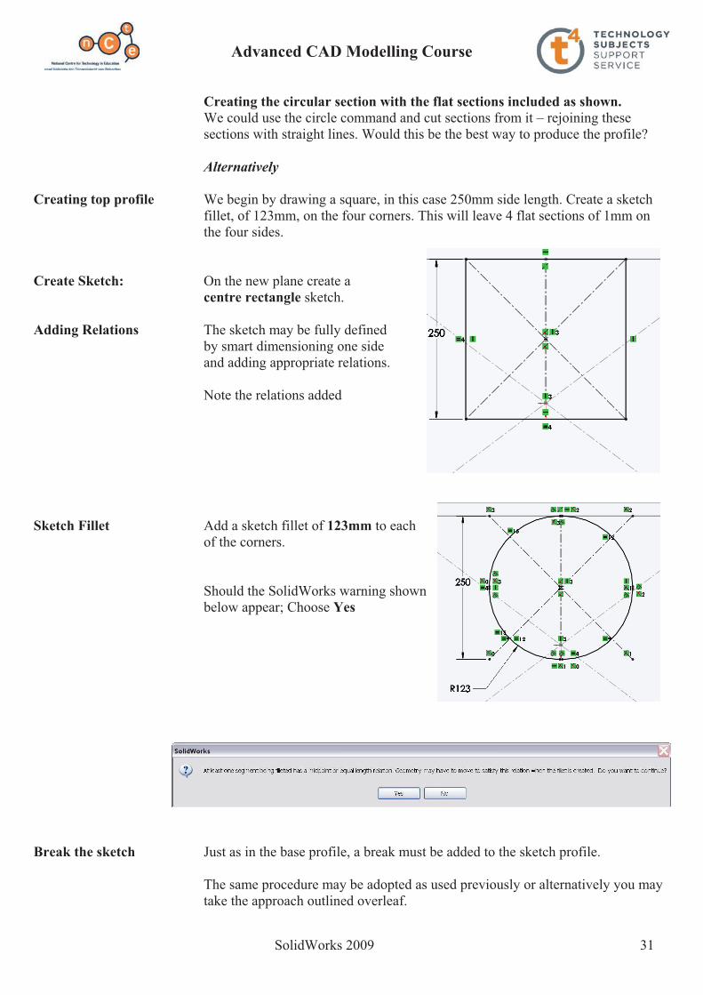
Creating top profile We begin by drawing a square, in this case 250mm side length. Create a sketch fillet, of 123mm, on the four corners. This will leave 4 flat sections of 1mm on the four sides.
Create Sketch: On the new plane create a centre rectangle sketch.
Adding Relations The sketch may be fully defined by smart dimensioning one side and adding appropriate relations.
Note the relations added
Sketch Fillet Add a sketch fillet of 123mm to each of the corners.
Should the SolidWorks warning shown below appear; Choose Yes
Break the sketch Just as in the base profile, a break must be added to the sketch profile.
The same procedure may be adopted as used previously or alternatively you may take the approach outlined overleaf.

Advanced CAD Modelling Course
SolidWorks 2009 32
Alternatively: We can use the break lines from the first sketch to create a break in this sketch using the convert entities sketch command.
Convert Entities This command allows elements from previous sketches or model edges to be converted into sketch entities. In this case it uses the break lines from the base profile sketch to create sketch segments in the current sketch.
Note: When using the Convert Entities command, you must pre select the elements of the sketch you wish to convert before selecting convert entities
Also
Using this command means that any changes made to the distance between the break lines in the base profile automatically updates in the top profile
Select sketch elements: What elements of the base profile sketch do we wish to convert for use in the top profile sketch?
The break lines from the base profile.
Multiple Selections Select the break lines - To select more than one line from the sketch you must hold down the Ctrl button while selecting the lines.
Convert Entities With the break lines and the top profile Selected, choose Convert Entities

Advanced CAD Modelling Course
SolidWorks 2009 33
This will now convert the break lines into sketch lines within the top profile sketch.
Construction Geometry Note: these new lines must now be changed into construction lines, and then the area between them must be trimmed in the same way as we did in the first sketch.
Exit the sketch and rename top profile
Completed Sketches The completed sketches of the top and base profiles.
Creating the Feature: Note: In order to create a lofted bend feature we must have exited both sketches, as both will be used to create the feature.
Lofted Bend Select Lofted bend from the sheet metal toolbar
Profiles Select the sketch profiles to create the loft Sketch1 - Base Profile Sketch2 - Top Profile
Note: When choosing the two sketches pick corresponding parts of both sketches to avoid forming a warped surface.
Thickness Enter a Thickness of 0.5mm
Bend Lines The number of bend lines used to create the transition piece may be controlled here.
Choose 4 bend lines.

Advanced CAD Modelling Course
SolidWorks 2009 34
Click OK to confirm
Hiding the Plane: Left click on plane1 in the feature manager tree and select Hide
Flatten Choose Flatten
The transition piece development is displayed.
Note: 4 bend lines at each transition.
Creating a drawing: As with any Solidworks part, a drawing may be produced by selecting File, Create drawing from Part/Assembly or
Choose from the standard toolbar
When a drawing is created from a sheet metal part, in addition to the standard views, the opportunity exists to create a view which displays the development of that part.
Create Drawing: With the part file open select File, Create drawing from part/assembly.
Select DCG A3L as the drawing template you wish to use.
Standard Views All of the standard drawing views are displayed in the Task Pane
Any of these views may be dragged and dropped onto the drawing sheet.
Flat pattern Flat Pattern is included in these views.
Dragging this icon into the sheet will generate a view displaying the development of the prism.

Advanced CAD Modelling Course
SolidWorks 2009 35
Creating the view layout To generate the solution we want to create 3 orthographic views and add the surface development of the transition piece
Drag the Front View onto the sheet and project a Plan view from the parent view. Use a scale of 1:5
Adding the surface To add the surface development, select Model View fromdevelopment: the View Layout toolbar.
Model View Choose Extractor Hood from the Opendocuments list in the Model View options dialog box.
Select next to proceed
Flat Pattern Select the Flat Pattern option
Position the flat pattern view on the drawing sheet.
Choose OK.
Positioning the views Drag the views to position them on the sheet.
Note: The text may be removed from the surface development by right clicking on it and choosing Hide.

Advanced CAD Modelling Course
SolidWorks 2009 36
Save & Close Save all SolidWorks Documents. Lesson Complete!

Advanced CAD Modelling Course
SolidWorks 2009 37
Convert to Sheet Metal - Golf Ball Package
Prerequisite knowledge: Sheet metal exercises 1, 2, and 3, should be completed in advance of this exercise.
Focus of lesson: To convert solid features to sheet metal and to use sheet metal to create a surface development.
Commands Used: This lesson includes Sketching, Lofted Bend, Flatten, Extruded Cut and Convertto Sheet Metal.
Problem: The development of the Golf ball package is to be created using SolidWorks. The box is based on a square based pyramid. The window is created with a cut generated by a cylinder. Generate the pyramid, removing the cut material for the window. Retrieve the development of the box using sheet metal features.
New File Create a new part file.
Save File Save the file to a chosen location as Package development.We will explore the use of SolidWorks in completing the problem, focusing on sheet metal features.

Advanced CAD Modelling Course
SolidWorks 2009 38
The approach The square based pyramid must first be modelled and the development of the package created from it. As the pyramid is to be cut with a cylindrical feature, we will create it as a solid. We will then convert it to a sheet metal component in order to generate its development.
What geometric shapes are used?
The main body of the package is created by modelling a square based pyramid.
The cut surface is generated by cutting the pyramid with a cylinder to give a circular cut when viewed from the right or left.
Getting Started How will we create the pyramid? In exercise three we created the transition piece using lofted bend. We will
use lofted bend again to create the pyramid.
What two sketch profiles must we create?
Base: Square
Top: Point
Creating Base Sketch: What Plane will we create the Sketch on? Because the pyramid sits on the Horizontal Plane, we will create our sketch on the top plane.
Create the sketch shown on the top plane. Use only the dimension shown. Add appropriate relations
Side: 100mm Exit Sketch In order to create the second sketch we must first exit this sketch.

Advanced CAD Modelling Course
SolidWorks 2009 39
Creating Top Profile: The top profile is positioned a height of 100mm above the base profile.
How will we create the profile 100mm above the base profile? We must begin by creating a plane on which to sketch.
From Features select Reference geometry and Plane.
Create a plane 100mm above the Top plane.
Creating sketch As the pyramid forms a point at the apex, we will use point to create the top profile.
Note: by creating the base profile with the origin as centre it allows us to use the origin to alignboth profile sketches.
Select the new plane as the sketch plane. From the sketch toolbar select pointPosition a point on the origin as shown. This will ensure that the point is positioned directly over the centre of the rectangular base thus producing a right pyramid.
Exit the Sketch Exit sketch.
Creating the Feature: Note: In order to create a lofted bend feature we must have exited both sketches, as both will be used to create the feature.
Loft Select Loft from the features toolbar
Profiles Select the sketch profiles to create the loft
Sketch1: Base Profile Sketch2: Top Profile
Click OK to confirm

Advanced CAD Modelling Course
SolidWorks 2009 40
Creating the Cut The pyramid is to be cut by a cylinder. In order to create this cut we will need to sketch a circle to extrude cut through the pyramid.
The cylinder cuts through the pyramid therefore the sketch is placed on the right plane which cuts the pyramid symmetrically. A mid- plane extrusion will be used to create the cut.
Due to the prudent location of the origin we can use the Right plane on which to sketch.
Create Sketch Create the sketch shown on the Right plane
Creating the feature Create an Extruded Cut feature using a Through All end condition in both directions.
Click OK.

Advanced CAD Modelling Course
SolidWorks 2009 41
Surface Development A cut pyramid has now been created but SolidWorks cannot create a development from a solid model. We must convert the model to a sheet metal part in order to retrieve the surface development.
Convert to sheet metal In Solidworks 2009 solid models can be converted to sheet metal. Using this feature will allow us to create a development from this model.
Choose Convert to sheet metal from the sheet metal toolbar.
When converting to sheet metal you will be required to choose;
� a fixed face, about which the development will be created � corners which will become bends � edges along which you wish to cut or rip the feature to flatten it out
Selecting a fixed face: Any face may be selected as the fixed face.
We will select one of the faces that are not cut by the cylindrical hole.
Face 1 is entered as the selected face.

Advanced CAD Modelling Course
SolidWorks 2009 42
Selecting Bend Edges: The bend edges must be selected. Select each of the bends on the model.
As the bends are selected, SolidWorks will automatically select the edges which will be used as rip edges.
Further parameters The following parameters must be set;
Sheet thickness: 0.1mm
Bend radius: 0.1mm
Gap size: 0.25mm
Click OK.
The pyramid has now been converted to sheet metal.
Design Tree Sheet Metal features have been added to the Feature Manager Design Tree.
Surface Development Right click on Flat-pattern in the design treeand choose Unsuppress.

Advanced CAD Modelling Course
SolidWorks 2009 43
Creating Curved Features SolidWorks 2009

Advanced CAD Modelling Course
SolidWorks 2009 44
Helical Slide Exercise
Prerequisite knowledge A basic knowledge of SolidWorks 2009 is required – use of sketching and extrude boss/base.
Focus of Lesson This lesson will focus on creating a 3-dimensional solution to the geometry problem posed using SolidWorks.
Commands Used This lesson includes Sketching, Helix, Surface Sweep, Sketch Sharing andExtrude Boss/Base.
Getting Started A helix is a curve which lies on the surface of a cylinder or cone. A cylindrical helix is formed by a point moving uniformly at a constant rate around a cylinder.
Create Sketch Create a sketch of a circle on the Top plane using the dimensions shown. Position the sketch so that the origin is coincident with the centre point of the circle.
This circle will be the basis for generating the helix.
Exit the sketch and rename it to Profile of Helix in the Design tree.

Advanced CAD Modelling Course
SolidWorks 2009 45
Creating Helix Select the profile and chooseHelix and Spiral from the features toolbar under Curves.
Or choose; Insert, Curves, Helix/Spiral
Helix/Spiral The Height and Revolution option will be Property Manager used to create the helix.
Parameters Height: 144mm, given in the question. Height defines the height from the profile.
Reverse direction brings the height above or below the plane the profile exists in.
Revolutions: 1.5 Revolutions defines the number of turns,
in this particular case we require 1.5 revolutions.
Start Angle defines the start point of the helixon the sketched circle.Start angle: 90°
Choose OK
The profile sketch is incorporated into the feature and so is out of our view.
Rename feature Rename the Helix/Spiral as Slide Path.
Choose Top View. The helix appears as the profile circle in plan.

Advanced CAD Modelling Course
SolidWorks 2009 46
Slide Select front plane and create the following sketch. Ensure that the endpoint of the horizontal line is coincident with the start point of the helix as shown.
Rename the sketch Slide Profile.
Surface Sweep Surface Sweep command works in the same way as the feature Swept Boss/Basehowever the surface produced is infinitely thin. The question outlined at the start directs us to ignore wall thickness of the chute.
Swept Boss/Base uses a closed sketch and produces a sweep which has thickness. Swept Boss/Base cannot use open sketches as we have here.
Locating the command Add in the surfaces tool bar to the features command manager.
Locate the swept surface option under this menu.
Profile - slide profile Path - Slide path
Choose OK Rename the surface sweep as Slide.

Advanced CAD Modelling Course
SolidWorks 2009 47
Finish Slide Identify the Profile of Helix sketch. This sketch will be used to generate the cylinder.
Note: The advantage of using this circle is; should the helical diameter change, the cylinder will update accordingly.
How to find the circle: Click the plus sign beside Slide
Click the plus sign beside slide path
Right click on Profile of Helix and select show.
Extruded Support Extrude this sketch using the feature Extrude Boss/Base with the end constraint set as Up to Vertex. Choose the top vertex on the slide to be your height. This will keep the extrude referenced to the slide if the height of the helix (slide) is altered.
Rename the extrude Slide support.
Note - Notice the icon representing the sketch for Profile of Helix.
In the same way as shared folders represented on your computer shared sketches have a similar icon to describe the fact that they are shared.

Advanced CAD Modelling Course
SolidWorks 2009 48
Appearance The solid is now complete. However, we can see there is a problem with the surface of the cylinder and the surface of the inner wall of the slide – to accurately complete the question we will manipulate the transparency of the cylinder and allow the slide to overlay it.
Transparency Right click on the feature called Slide Support in the feature manager design tree and select Appearance.
Choose an appropriate colour from the color palette.
Transparency is present under Optical Properties - Set the Transparency to 0.70
Slide Colour Apply a colour to the slide in the same way.
Note: No transparency required for the slide

Advanced CAD Modelling Course
SolidWorks 2009 49
Drawing Make a drawing file from the part Ensure to give the drawing the shaded with edges display under display style – a
surface in SolidWorks has no thickness therefore will not be seen unless the above step is taken.

Advanced CAD Modelling Course
SolidWorks 2009 50
Projected Curve & Lofted Boss/Base – Hand Soap Bottle
Prerequisite knowledge A basic knowledge of SolidWorks 2009 is required – use of sketching and extrude boss/base.
Focus of Lesson This lesson will focus on using the following feature commands- Lofted boss/base with 3 guide curves, Spline and Project Curve.
Commands Used This lesson includes Sketching (Spline), Loft boss/base, projected curve, Swept boss/base and Extrude boss/base.
Getting Started Create the following sketch of an ellipse on the top plane using the dimensions shown. Position the sketch suchthat the origin is at the centre of the sketch.
Note the vertical relation to fully define the sketch.
Save Save the part as Soap Bottle Add the two vertical lines as shown. Smart dimension and add the necessary
relations to fully define the sketch.
Trim the ellipse using the two lines Exit sketch and rename it profile1.

Advanced CAD Modelling Course
SolidWorks 2009 51
Creating Profile 2 The second sketch used to define the loft must be created at a height of 105mmabove profile1.
We must first create a plane on which to sketch.
Offset Plane Choose Insert, Reference Geometry, Plane
Define Plane Selections:
Top Plane Offset Distance: 105mm.
Sketch Create the circular sketch shownon Plane 1.
Close sketch and rename it as Profile2.
Creating the bottle We are going to use Lofted Boss/Base to create the bottle shape, however we will direct the shape of the transition between the two sketches using guide curves.
The guide curves will be generated as sketches using the Spline tool.
Splines Spline draws a freeform curve. Splines may form either a single closed loop or an open loop. In either case the spline is not allowed to cross itself.
You can draw a spline by clicking each location where you want to add a control point. Splines are used mainly for freeform complex shapes in 2d and 3d sketches, although you can also use them for anything that you would use other sketch elements for.

Advanced CAD Modelling Course
SolidWorks 2009 52
Creating Guide Hide Plane 1. Choose Front View. Curves Create a sketch on the front plane. Choose Spline from
the sketch toolbar.
Sketch a spline with its start and end points coincidentwith profile1 and profile2 respectively.
Ensure there are 7 points in total on this spline. Start and finish with 5 in between.
Note: To end the spline; right click and choose Select.
Cartesian Method We will use Cartesian Coordinates to identify the position of spline points and hence drive the shape of the spline.
To give the spline points their Cartesian Coordinates double click on the spline.
Spline point number - where on the spline the point is located
X and Y axis – based on the Cartesian Coordinate System.
Using the values in the table, index through the seven spline point numbers and assign the coordinates for each spline point.
Exit the sketch and rename as guide curve1.
Guide Curve 2 The guide curve on the opposite side will be a mirror image of guide curve1 as the bottle is symmetrical.
Create a new sketch on the front plane.
Select guide curve1 and choose Convert Entities
This sketch will be projected onto the sketch plane and may now be used as sketch geometry.
Point X Axis Y Axis1 -40.524 02 -44 10.5 3 -48 374 -48 56 5 -40.50 816 -25 100 7 -12.5 105

Advanced CAD Modelling Course
SolidWorks 2009 53
Mirror Entities Add in a centreline as shown and mirrorthe curve about the centerline.
For Construction The curve on the right hand side will be used as a guide curve to create the Lofted Boss/Base
The ‘Convert Entities’ curve, on the left, must be marked as Construction Geometry to ensure it is ignored when using the sketch as a guide.
Select the curve on the left and choose Construction Geometry in the pop-up menu.
Exit the sketch and rename as guide curve2.
Note: If Guide Curve1 is edited guide curve2 will automatically update to reflect those changes.
Guide curves 3 & 4 Guide curves 1 & 2 will drive the shape of the left and right hand sides of the bottle. Sketches representing guide curves 3 & 4 must be created to drive the profile of the front and back of the bottle.
Guide curves 3 & 4 will be created using the same steps with different spline point coordinates.
Create Sketch Create a sketch on the Right plane.
Sketch the spline shown using the following Cartesian Coordinates.
Exit Sketch Exit the sketch and rename guide curve3
Point X Axis Y Axis1 -23 02 -25 8 3 -24 104 -22 19 5 -22 496 -18 96 7 -12.5 105

Advanced CAD Modelling Course
SolidWorks 2009 54
Guide Curve4 Guide Curve4 will be created in the same way as guide curve2 as the bottle is again symmetrical in this direction.
Create sketch Create a new sketch on the Right plane. Choose Right View.
Convert Entities Use Convert Entities to convert guide curve3 onto the plane.
Sketch the vertical centerline, coincident with the origin and mirror the curve about the centreline.
Remember: The ‘Convert Entities’ curve, on the left,must be marked as Construction Geometry.
Select the curve on the left and choose Construction Geometry in the pop-up menu.
Exit the sketch and rename guide curve4.
The model should now appear as shown.
Lofted Boss/Base Choose Lofted Boss/Base and create a Loftbetween Profile1 and Profile2.
Without the influence of the guide curves the loftwill appear as shown.
Guide Curves Highlight the Guide Curves dialog box
Select one of the guide curves and choose OK
Repeat the procedure to capture all of the guide curves.
Rename loft as Body of Bottle

Advanced CAD Modelling Course
SolidWorks 2009 55
Neck Feature We will use a Swept Boss/Base to create the feature shown on the neck of the bottle.
In order to generate a sweep we must create a profileand a path around which to sweep the profile.
These will be created as two separate sketches.
Path Sketch Create the sketch shown on the top surface of the bottle using centre rectangle, coincident with the origin, and a sketch fillet of 8mm.
Exit the sketch and rename neck path.
Profile Sketch Choose Right View.
Create the sketch shown on the Right plane.
Exit the sketch and rename neck profile.
Neck of Bottle Choose Swept Boss/Base Choose the profile and path as indicated
below.
Choose OK.
Rename the feature Bottle Neck.

Advanced CAD Modelling Course
SolidWorks 2009 56
Cylindrical Feature We will use profile2, a circle of Ø25, which was used to define the loft earlier, as the sketch to create the cylindrical feature on the top of the bottle.
Show Sketch Expand the Body of bottle feature.
Select profile2 and choose Show.
Extruded Boss/Base Extrude this sketch a distance of 10mm.
Fillet Add a 2mm fillet around the base ofthe cylindrical feature.
Embossed Label The label on the front of the bottle is contained within a raised profile. This embossed profile will be created as a Swept Boss/Base. The profile for the sweep will be a circle of diameter 2.5mm. The path must be positioned on the face of the bottle.
Because the face of the bottle is not planar we must pursue another method of creating the path.
Projected Curve Allows you to project a sketch onto a model face to create a 3D curve.
We will begin by creating the sketch on the Front plane. Ensure that the centre of the rectangle is vertically above the origin.
Use sketch fillet to apply an 8mm fillet to the corners of the rectangle.
Close the sketch and rename it label.
Position of sketch

Advanced CAD Modelling Course
SolidWorks 2009 57
Projected Curve Choose Projected curve from the Curves menu, on the features toolbar.
Selections:
Sketch on faces.
Label as the sketch to project
Front face as Projection Faces
The sketch will project onto the face and will be represented as in the design tree.
This 3D curve will act as the path for the Swept Boss/Base.
Rename the feature label path
Label profile The profile for the label is a circle of Ø2.5mm. This sketch will be positioned on the right plane perpendicular to the label path.
Create a sketch on the right plane of a circle Ø 2.5mm.
Pierce Relation The Pierce relation will make the centre ofthe circle coincident with the label path.
Select the centre of the circle and the projected curve
using ctrl.
Choose from the properties dialog box.
Exit the sketch and rename it label profile.
Swept boss/base Create a swept boss/base feature using the following parameters;
Profile: label profile Path: label path
Choose OK.
Rename the feature as label area.

Advanced CAD Modelling Course
SolidWorks 2009 58
Shell bottle Shell the entire feature using a thickness of 1mm, choosing the top face as facesto remove.
Appearance Apply an appropriate appearance to the part.
Use optical properties to reduce the transparencyof the part.
Apply different appearance settings to the label face
with transparency setting of zero.
Lesson Complete!

Advanced CAD Modelling Course
SolidWorks 2009 59
Introduction to Curves & Splines - Countersunk Screw
Prerequisite knowledge A basic knowledge of Solidworks 2009 is required – use of sketching and extrudeboss/base.
Focus of Lesson This lesson will focus on using the following feature commands; Helix and Circular Pattern.
Commands Used This lesson includes Sketching, Extrude boss/base, Helix, Swept boss/base andExtruded Cut with Circular Pattern.
Getting Started We will begin by creating the straight helical portion of the screw.
Create a sketch of a circle on the Top plane of diameter 5mm.
Position the sketch such that the origin is coincident withthe center point of the circle.
Exit sketch and rename it profile1.
Save as Save the part as Countersunk screw Helix Use profile1 as the sketch to create the Helix.
Choose the Pitch and Revolution option as the means of defining the helix.
Set the Pitch to 2mm and Revolutions to 12.
The Start angle, ie where to start the first turn on the sketch circle, is 90°. Choose OK.
Rename the feature straight helix.
Create Sketch We will create the profile of the screw thread next.

Advanced CAD Modelling Course
SolidWorks 2009 60
Sketch the equilateral triangle shown on the front plane.
The sketch is based on an equilateral triangle with an inscribed circle, marked for construction.
Ensure to pierce the centre point of the construction circle with the straight helix.
Close the sketch and rename sweep profile1. Swept boss/base Use sweep profile1 as the profile and the straight helix as the path.
Rename the sweep as thread1.
Extrude boss/base Select the profile1 sketch from the feature manager design tree; choose Show.
This sketch will be used to generate the cylindrical part of the screw.
Extrude upwards a distance of 40mm.
Rename the extruded feature body of screw.
The lower portion of the screw has a tapered helix. We will again use the Helix/Spiral feature to create this, with some different parameters.
Create Sketch Select the Top plane and create the same sketch as profile1;Circle diameter 5mm, origin coincident with the circle centre.
Rename the sketch profile2
Tapered Helix Defined by: Pitch and Revolution
Pitch: 2mm
Reverse Direction
Revolutions: 4
Start angle: 90°
Counterclockwise Tapered Helix of 15°. Choose OK
Rename Rename feature tapered helix
Advanced CAD Modelling Course
SolidWorks 2009 61
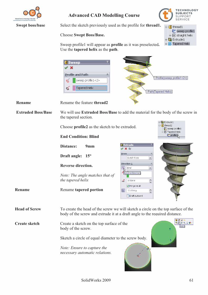
Swept boss/base Select the sketch previously used as the profile for thread1.
Choose Swept Boss/Base.
Sweep profile1 will appear as profile as it was preselected.Use the tapered helix as the path.
Rename Rename the feature thread2
Extruded Boss/Base We will use Extruded Boss/Base to add the material for the body of the screw in the tapered section.
Choose profile2 as the sketch to be extruded.
End Condition: Blind
Distance: 9mm
Draft angle: 15°
Reverse direction.
Note: The angle matches that ofthe tapered helix
Rename Rename tapered portion
Head of Screw To create the head of the screw we will sketch a circle on the top surface of the body of the screw and extrude it at a draft angle to the required distance.
Create sketch Create a sketch on the top surface of the body of the screw.
Sketch a circle of equal diameter to the screw body.
Note: Ensure to capture the necessary automatic relations.

Advanced CAD Modelling Course
SolidWorks 2009 62
Extruded Boss/Base Extrude this sketch with the following parameters;
Rename feature Head of Screw Screwdriver cutout Because the cutout for the screwdriver is symmetrical across two axes, we can
create one simple sketch, create an extruded cut feature from that sketch and then create a circular pattern using that feature.
Create sketch Select the top surface on the head of screwand complete the following sketch.
Ensure the origin is the midpoint of thevertical line on the left side of rectangle.
Close the sketch and rename as head sketch
Extruded Cut Cut extrude the sketch down into head of screw a distance of 2mm.
Rename the feature screw head cut.
Circular Pattern 1 In order to create the circular pattern we must have an axis around which to pattern.
Temporary Axes Choose View, Temporary Axes. An axis for the part will appear as a blue chain line.
Circular Pattern Select circular pattern from the features tools.
Select the temporary axis as the Pattern Axis
Angle: 360° Number of instances: 4 Equal Spacing
Choose screw head cut as the features to pattern.
Choose OK

Advanced CAD Modelling Course
SolidWorks 2009 63
Circular pattern 2 Taking a look at the completed model, we can seethat there is a second cut to be made to complete the head of the screw.
In order to create this cut we must first create the triangular profile of the cut.
This profile will be created on a plane at 45° to the front plane.
Reference geometry To create the plane choose Insert, Reference Geometry, Plane
This plane will be defined as making an angle of 45° to the front plane and the temporary axis lies on it.
Reference Entities: Front Plane Temporary Axis
Angle: 45° Create Sketch Create the sketch shown on plane 1. Exit the sketch, rotate the model and note the
position of the sketch.
Rename Rename the sketch as head sketch1
Extruded Cut Extrude cut this sketch with the following parameters: Distance: 3mm Draft: 6°
Advanced CAD Modelling Course
SolidWorks 2009 64
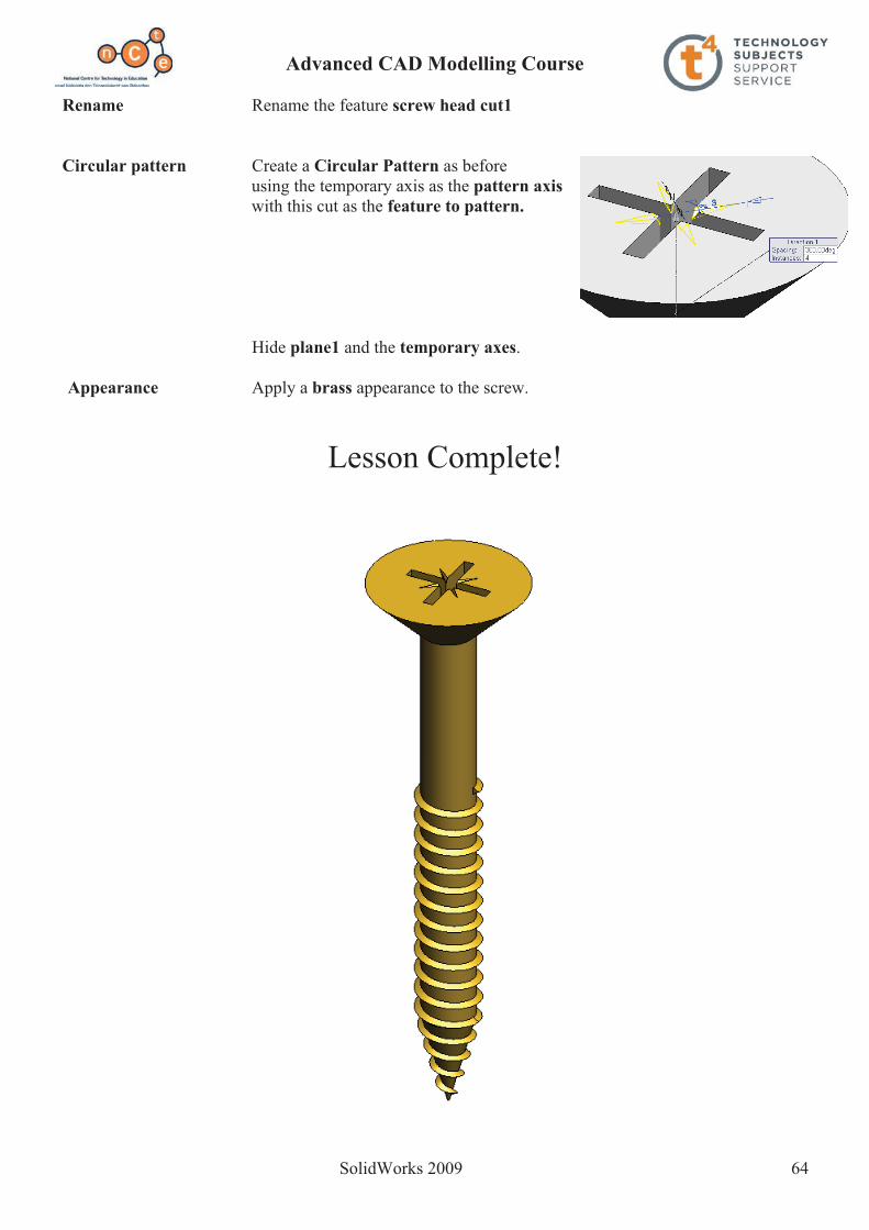
Rename Rename the feature screw head cut1
Circular pattern Create a Circular Pattern as before using the temporary axis as the pattern axiswith this cut as the feature to pattern.
Hide plane1 and the temporary axes.
Appearance Apply a brass appearance to the screw.
Lesson Complete!
Advanced CAD Modelling Course
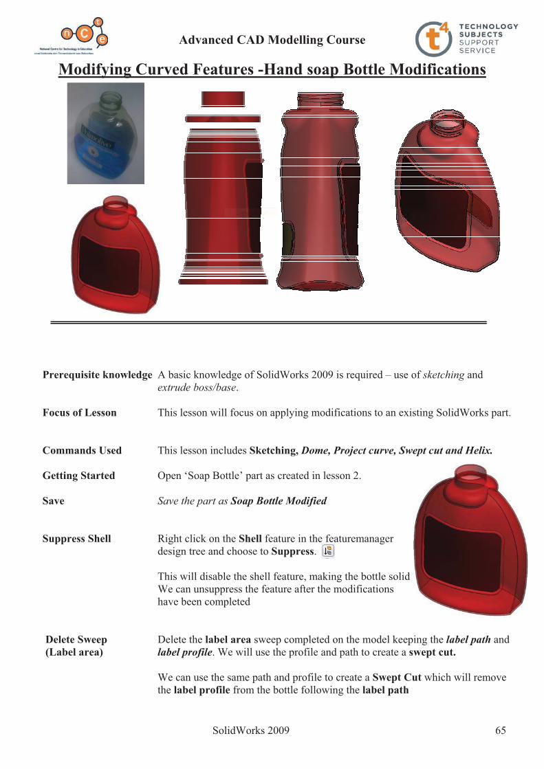
SolidWorks 2009 65
Modifying Curved Features -Hand soap Bottle Modifications
Prerequisite knowledge A basic knowledge of SolidWorks 2009 is required – use of sketching and extrude boss/base.
Focus of Lesson This lesson will focus on applying modifications to an existing SolidWorks part.
Commands Used This lesson includes Sketching, Dome, Project curve, Swept cut and Helix.
Getting Started Open ‘Soap Bottle’ part as created in lesson 2.
Save Save the part as Soap Bottle Modified Suppress Shell Right click on the Shell feature in the featuremanager
design tree and choose to Suppress.
This will disable the shell feature, making the bottle solid We can unsuppress the feature after the modifications have been completed
Delete Sweep Delete the label area sweep completed on the model keeping the label path and (Label area) label profile. We will use the profile and path to create a swept cut.
We can use the same path and profile to create a Swept Cut which will remove the label profile from the bottle following the label path

Advanced CAD Modelling Course
SolidWorks 2009 66
Swept Cut Select Swept Cut from the features toolbar.Choose:
label profile as the profilelabel path as the path
Choose OK.
Rename swept cut as label indent.
Dome The base of the model is flat. In reality the underneath of the soap bottle is curved inwards. This curved geometry may be added using the Dome feature.
The dome feature allows you to add a dome to planar and non-planar surfaces.
Adding the dome Select the bottom surface of the bottle and choose dome
Apply the following settings:
Distance 6mm
Reverse direction Choose Reverse Direction
This ensures the dome is applied to the inside of the bottle and not protruding
below the model. Choose OK.
Rename the feature as Base.
Fillet We will use the fillet command to add more rounded contours to the model to mimic the original model.
Choose Fillet.
Select the FilletXpert tab.
Choose a radius of 5mm.
Select an edge at the base. A pop-upmenu appears with a number of pre-selected edges based on thechosen edge.
From the pop-up menu choose Connected 19, Edges.
Choose OK.

Advanced CAD Modelling Course
SolidWorks 2009 67
Rear Label We will add another label area to the rear of the bottle using the same procedure as was used to create the front label area.
Create the sketch shown on the front plane.
Sketch Fillet Apply an 8mm sketch fillet to all corners of the rectangle
Project Curve Using Project Curve, project the sketch onto theback face of the bottle.
Cut Sweep Create a profile for the cut sweep.
The Profile is a Ø1mm circle drawn on the right plane and pierced with the path.
Path – the projected curve just created.
Rename the feature rear label indent.
Helix (Thread) A helix is required to create the thread on the top of the bottle. This helix will be based on a profile circle located 3 mm above the neck of the bottle.
Insert Plane Choose Insert, Reference geometry, plane…
Select Plane1 as reference entities and a distance of 3mm.
Choose OK.
Create Sketch Create a sketch on Plane2.
Choose TopView.
Convert Entities Select the circular profile andchoose Convert Entities.
Advanced CAD Modelling Course
SolidWorks 2009 68
This will create a circular profile sketch on plane2
Exit the sketch.
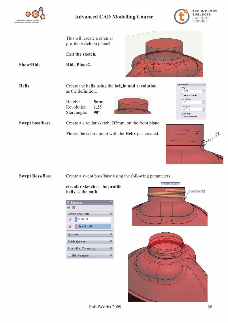
Show/Hide Hide Plane2.
Helix Create the helix using the height and revolution as the definition.
Height: 5mmRevolution 1.25Start angle: 90°
Swept boss/base Create a circular sketch, Ø2mm, on the front plane.
Pierce the centre point with the Helix just created.
Swept Boss/Base Create a swept boss/base using the following parameters:
circular sketch as the profilehelix as the path
Advanced CAD Modelling Course
SolidWorks 2009 69
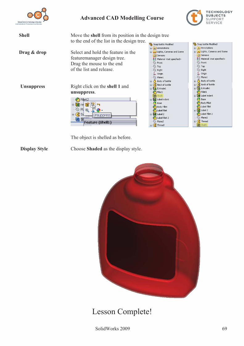
Shell Move the shell from its position in the design tree to the end of the list in the design tree.
Drag & drop Select and hold the feature in the featuremanager design tree. Drag the mouse to the end of the list and release.
Unsuppress Right click on the shell 1 and unsuppress.
The object is shelled as before.
Display Style Choose Shaded as the display style.
Lesson Complete!

Advanced CAD Modelling Course
SolidWorks 2009 70
Composite Curve – Wire Clothes Hanger
Prerequisite knowledge A knowledge of SolidWorks 2006/2009 is required – use of sketching, helix andswept boss/base.
Focus of Lesson This lesson will focus on using Composite Curve.
Commands Used This lesson includes Helix, 3D Sketch, Composite Curve & Swept Boss/Base.
The hanger will be created using Swept Boss/Base. The profile will be a circle. The path will be made up of 3 separate sketches. These 3 sketches will have to be joined to form one curve in order to use it as the sweep path.
Getting Started Create a new part file & save as Wire Clothes Hanger.
Create Sketch Create the sketch shown on the front plane.
Exit Sketch

Advanced CAD Modelling Course
SolidWorks 2009 71
Helix The neck of the clothes hanger is based on a helix. The helix is based on a Ø8mm circle.
Create sketch Create the sketch shown on the Top plane.
Note the prudent positioning of the origin at the outset.
Helix Choose Curves, Helix and Spiral.
Choose the circular sketch as the basis for the helix.
Define the helix using the following parameters;
Height and Revolution
Height: 30mm Revolutions: 4 Start Angle: 180° Counter Clockwise
Choose OK.
3D Sketch To complete the path we must join the helical curve to the initial sketch. We will create a 3D sketch line to join their endpoints.
Choose 3D sketch from the Sketch toolbar. Select line.
Add a 3D sketch line coincident with the endpoint of the helix and sketch1, as shown.
Exit the 3D sketch using the Confirmation Corner

Advanced CAD Modelling Course
SolidWorks 2009 72
Composite Curve At the moment the sweep path is made up of Sketch1, the helix and the 3D sketch joining the endpoints of both. As discussed earlier, these 3 entities must be joined together to form one curve. The Composite Curve feature enables us to do this.
Choose Composite Curve from the features toolbar.
Make Selections Select the aforementioned as entities to join.
Choose OK. The 3 entities will be consumed under the composite curve feature in the design tree.
Rename the feature hanger path.
Hanger Cross-section The cross-section of the hanger is a circle of Ø4mm. This will act as the profile for the swept boss/base.
Insert Plane Prior to creating the sketch representing the circular cross section we must first create a plane on which to sketch.
Choose Insert, Reference Geometry, Plane.
Select Normal to curve option.
Choose the line and point as shown.
Choose OK.
Create Sketch Create a circular sketch of Ø4mm on the plane.
Add a pierce relation between the centre of the circle and the composite curve.
Rename the sketch hanger profile.

Advanced CAD Modelling Course
SolidWorks 2009 73
Swept Boss/Base Create a swept boss/base using;
hanger profile as the swept profile hanger path as the swept path.
Show/hide Hide Plane1.
Appearance Add an appropriate appearance to the model
Lesson Complete!

Advanced CAD Modelling Course
SolidWorks 2009 74
Working with Surfaces SolidWorks 2009

Advanced CAD Modelling Course
SolidWorks 2009 75
Surface Modelling In surface modelling a model is built face by face. Faces created by surface features may knit together to enclose a volume, which may be turned into a solid model.
Surface modelling is used to create faces and features which may not be conveniently produced using solid modelling techniques. Surface tools are employed in situations where they make it easier, more efficient or even possible to complete the task at hand.
The focus of this exercise is to give a basic introduction to surfaces and explore the functionality of some surfacing tools.
As we work through the exercise we will explain the terminology associated with surfaces.
Prerequisite knowledge To complete this model you should have a working knowledge of Solidworks 2006/2009.
Focus of lesson This lesson focuses on using the following surface tools; Filled Surface, SurfaceThicken and Cut with Surface as well as Shell and Extrude feature tools.
Getting started
Plastic Medicine Spoon
Advanced CAD Modelling Course
SolidWorks 2009 76
New File Create a new part file and save it as Plastic Medicine Spoon in the desired location.
New Sketch We are going to begin by creating a sketch to represent the top profile of the spoon. Create a sketch on the Top plane.
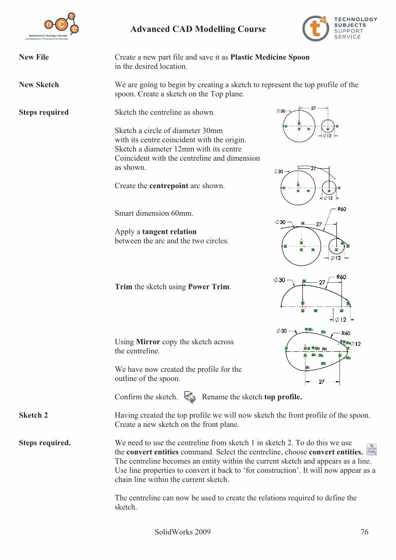
Steps required Sketch the centreline as shown.
Sketch a circle of diameter 30mm with its centre coincident with the origin. Sketch a diameter 12mm with its centre Coincident with the centreline and dimension as shown.
Create the centrepoint arc shown.
Smart dimension 60mm.
Apply a tangent relation between the arc and the two circles.
Trim the sketch using Power Trim.
Using Mirror copy the sketch across the centreline.
We have now created the profile for the outline of the spoon.
Confirm the sketch. Rename the sketch top profile. Sketch 2 Having created the top profile we will now sketch the front profile of the spoon.
Create a new sketch on the front plane.
Steps required. We need to use the centreline from sketch 1 in sketch 2. To do this we use the convert entities command. Select the centreline, choose convert entities.The centreline becomes an entity within the current sketch and appears as a line. Use line properties to convert it back to ‘for construction’. It will now appear as a chain line within the current sketch.
The centreline can now be used to create the relations required to define the sketch.

Advanced CAD Modelling Course
SolidWorks 2009 77
Use circle and centrepoint arc create the following sketch.
Smart dimension the sketch and apply the relations shown.
Now we have the profile for the curvature of the spoon when viewed from the front.
Confirm the sketch. Rename the sketch front profile.
Filled Surface Filled surface enables you to create a surface or ‘Patch’ defined by edges, lines or curves.
Steps required. Select the filled surface tool from the surfaces toolbar.
Select top profile as the patch boundary. This is the outline of the spoon.
Check Optimize surface to ensure that the patch or surface will finish at this outline.
A planar surface is now created within the boundary of this sketch.
Select front profile as the constraint curve. This curve will direct the surface to ‘bend’ to give the curvature required to create the surface.
Select OK
The surface is now created!
Rename the feature Rename the feature as Spoon.
From Surface To When a surface is created in SolidWorks itSolid has no thickness. If we take a section view through the surface we can see this.
To give the spoon wall a thickness we use the Thicken command from the surfaces toolbar.

Advanced CAD Modelling Course
SolidWorks 2009 78
Select Spoon as the surface to thicken.
Set the thickness to 0.5mm.
We have three options to choose from in order to thicken the surface. Selecting ‘Thicken side 1’ will thicken to the outside, ‘Thicken both sides’ will thicken either side of the surface, ‘Thicken side 2’ will thicken to the inside.
Choose Thicken Side 2
Select OK.
Trimming back You will notice that the surface thicken gives Surface thicken a bevelled finish to the edge of the spoon.
To correct this we will use Cut with surface to trim the excess off the top edge.
Cut with surface removes unwanted material by cutting with a surface or a plane.
As the Top Plane will conveniently cut the solid in this case it will be used as the cutting plane. Reverse direction if required.
Select OK.
The edge is now planar.
Creating the To create the handle we must first set up Handle a plane parallel to the Right Plane and create a sketch on that.
From the Surfaces menu select reference geometry, plane.
Select the Right Plane as a reference entity.
Check Reverse direction. Set the distance to 70mm.
Select OK

Advanced CAD Modelling Course
SolidWorks 2009 79
Sketch Sketch a corner rectangle on Plane1.
Apply a coincident relation between the midpoint of the top line of the rectangle and the origin as shown.
Confirm the sketch.
Extruding the Select Extruded Boss/Base from the Profile features menu. Select Up to Surface as the end condition. Select the outer surface of the spoon as the face/plane to extrude to.
Select OK
Rename the feature Rename the feature as ‘Handle’.
Hide Plane 1 Click on Plane 1 and select hide.
Fillet Apply a Full round fillet to the sides of the handle. Select the faces shown.
Select OK
The end of the handle is now rounded shown.
Shell Feature Select Shell from the Features menu. Select the underside of the Handle as the faces to remove.
Set the thickness to 0.5mm.
Select OK
Creating text Create the following sketch on the top surface of the handle.Feature
Select Text from the sketchmenu.
Make the following selections:

Advanced CAD Modelling Course
SolidWorks 2009 80
Select the centreline as the line for the text to follow.
Type in 5 ml as the text.
Select Century Gothic as font, set the units to 3mm and centre align the text.
Select OK
Extrude Text Select Extrude from the Features manager
Set the thickness to 0.25mm.
Select OK
Rename Feature Rename the feature as Text.
Select Material Set the material as PTFE.
Exercise complete!

Advanced CAD Modelling Course
SolidWorks 2009 81
Intersecting Lamina
Prerequisite knowledge To complete this model you should have a working knowledge of Solidworks 2006/2009.
Focus of lesson This lesson focuses on using SolidWorks to solve a geometrical problem. The following Surfaces tools are used: Planar Surface, Ruled Surface.
Problem The horizontal and vertical coordinates for two intersecting planesABC and DEF are given below.
A = 170 --- 95 --- 20
B = 215 --- 25 --- 30
C = 150 --- 55 --- 90
D = 235 --- 20 --- 25
E = 155 --- 5 --- 45
F = 160 --- 95 --- 70
(a) Draw the plan and elevation of the intersecting planes
(b) Determine the line of intersection between the planes
(c) Determine the dihedral angle between the planes

Advanced CAD Modelling Course
SolidWorks 2009 82
New File Create a new part file and save it as Intersecting Lamina in the desired location.
New Sketch We are going to begin by creating a sketch to represent the outline of portion of the Horizontal Plane.
Create the sketch shown on the Top plane.
Smart Dimension as shown.
We want to transform this rectangle into a Planar Surface.
Planar Surface Select Planar Surface from the Surfaces toolbar.
Select Sketch 1 as the Bounding Entities.
Select OK
Rename Feature Rename the feature as Horizontal Plane.
We have now created a portion of the horizontal plane. This planar surface has no thickness but can be used as a datum for measurements, a surface to project views onto, or a surface to sketch on.
The Vertical Plane To create the vertical plane we use Ruled Surface. Ruled Surface command creates surfaces that extend out in a specified direction and distance from selected edges.
Ruled Surface Select Ruled Surface from the Surfaces toolbar.
Select Normal to Surface as the Type. This will create a ruled surface at 90 degrees to another surface at a specified edge.
Set the distance to 150mm. This will extend the surface out 150mm from the selected edge. The width of the surface will be determined by the length of the edge selected.
Select the edge of the Horizontal Plane shown as the edge to set up the ruled surface from.
Select OK.
Rename Feature Rename the feature as Vertical Plane.

Advanced CAD Modelling Course
SolidWorks 2009 83
Positioning In order to use the XYZ Co-ordinates to position Co-Ordinates the points A, B and C, select 3DSketch from the
Sketch toolbar.
The co-ordinates are positioned as follows: The X value is the distance of the point from the Origin or the Right Plane.
The Y value is the distance of the point from the Horizontal Plane.
The Z value is the distance of the point from the Vertical Plane.
Using the front view we can see the X and Yvalues; using top view we can see the X and Z values;
use the right view to see the Y and Z values.
Rotate the sketch as shown so that when the points are dropped in we can avoid making them coincident with the two planes.
Using the Point command from the Sketchtoolbar, drop 3 points into the sketch as shown.
Select OK and press escape to exit the Pointcommand.
We must now enter the coordinates of the points. Select one of the points to access its co-ordinates
or parameters.
Enter the following values for the point.
Select OK.
Labelling the From the Insert dropdown menu, select Coordinates Annotations, Note
Make the endpoint of the arrowhead coincident with the points as shown, select Arial as the text, and label the point A.
Repeat this procedure for points B and C entering the co-ordinates as given at the beginning of the exercise.
N.B. to change the values of the coordinates you must first hide the annotations. This is done from the heads up toolbar. Select hide/show items, de-select annotations display.
Rename Feature Rename the 3DSketch as Ordinates Lamina ABC.
zx

Advanced CAD Modelling Course
SolidWorks 2009 84
Insert Plane We now want to create a lamina containing all three points. In order to do this we must create a
Plane which contains all three points.
Select reference geometry, plane
Choose through lines/points as entities for selection.
Select the three points A, B and C.
Select OK.
Creating the We can now create the lamina on this plane. Lamina Using the line command, create the following sketch on Plane1.
(Note the automatic relations)
Rename Sketch Rename the sketch as sketch abc.
Planar Surface Select Planar Surface from the Surfaces toolbar. We use planar surface so that if needs
be we can sketch on it or project lines/points onto it.
Select sketch abc as bounding entities.
Rename Feature Rename the feature as ABC
Select OK.
Hide Plane1.
Set the colour of ABC as shown.
Lamina DEF Create Lamina DEF following the same steps, and using its coordinates as given at the beginning of the exercise.
Set the colour of DEF as shown.
We have now created the intersecting lamina.
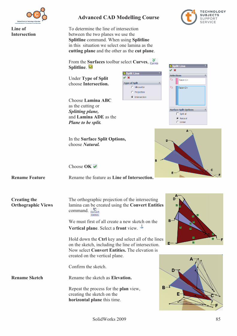
Advanced CAD Modelling Course
SolidWorks 2009 85
Line of To determine the line of intersection Intersection between the two planes we use the
Splitline command. When using Splitlinein this situation we select one lamina as the cutting plane and the other as the cut plane.
From the Surfaces toolbar select Curves,Splitline.
Under Type of Split choose Intersection.
Choose Lamina ABC as the cutting or Splitting plane, and Lamina ADE as the Plane to be split.
In the Surface Split Options,choose Natural.
Choose OK
Rename Feature Rename the feature as Line of Intersection.
Creating the The orthographic projection of the intersecting Orthographic Views lamina can be created using the Convert Entities
command.
We must first of all create a new sketch on the Vertical plane. Select a front view.
Hold down the Ctrl key and select all of the lines on the sketch, including the line of intersection. Now select Convert Entities. The elevation is created on the vertical plane.
Confirm the sketch.
Rename Sketch Rename the sketch as Elevation.
Repeat the process for the plan view, creating the sketch on the
horizontal plane this time.

Advanced CAD Modelling Course
SolidWorks 2009 86
Finding the In order to find the dihedral angle, i.e. the angleDihedral Angle between the two lamina we must take a point view of the Line of Intersection. In order to capture this view we must set up a plane perpendicular to the
Line of Intersection.
Choose reference geometry, plane
Select the midpoint of the Line of intersection as one of the selections. We do this so that if we enter different values for the coordinates, the plane will always set up on the midpoint of the line of intersection. N.B. this plane is for construction only. We will set up the plane required for the auxiliary view parallel to this.
Select the Line of Intersection as the other selection.
Choose normal to curve so that the plane will be perpendicular to the Line of Intersection.
Rename Feature Rename the plane as Perp. to LOI.
We now have the construction plane set up. The next step is to set up the plane onto which the auxiliary view will be projected.
Once again select reference geometry, plane
Select Perp to LOI as the reference plane, set the distance to 120mm.
Choose OK.
We now have the auxiliary plane that will Contain the required view. You will notice that the plane produced can be to the right or left of the initial plane, but it remains parallel to the plane. In order that the projected view will appear directly on the auxiliary plane we will create a portion of the auxiliary plane which has its centrepoint
coincident with the Line of Intersection.
Therefore if we want to change the coordinates to suit another similar problem, the auxiliary plane will always have its centrepoint coincident with the point view of the line of intersection.
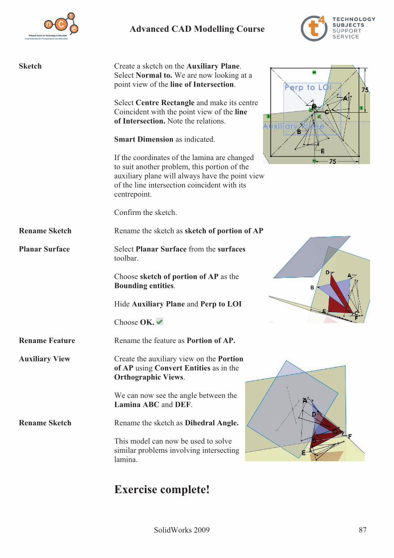
Advanced CAD Modelling Course
SolidWorks 2009 87
Sketch Create a sketch on the Auxiliary Plane. Select Normal to. We are now looking at a point view of the line of Intersection.
Select Centre Rectangle and make its centre Coincident with the point view of the line of Intersection. Note the relations.
Smart Dimension as indicated.
If the coordinates of the lamina are changed to suit another problem, this portion of the auxiliary plane will always have the point view of the line intersection coincident with its centrepoint.
Confirm the sketch.
Rename Sketch Rename the sketch as sketch of portion of AP
Planar Surface Select Planar Surface from the surfaces toolbar.
Choose sketch of portion of AP as the Bounding entities.
Hide Auxiliary Plane and Perp to LOI
Choose OK.
Rename Feature Rename the feature as Portion of AP.
Auxiliary View Create the auxiliary view on the Portion of AP using Convert Entities as in the
Orthographic Views.
We can now see the angle between the Lamina ABC and DEF.
Rename Sketch Rename the sketch as Dihedral Angle.
This model can now be used to solve similar problems involving intersecting lamina.
Exercise complete!

Advanced CAD Modelling Course
SolidWorks 2009 88
Prerequisite knowledge To complete this model you should have a working knowledge of Solidworks 2006/2009.
Focus of lesson This lesson focuses on using SolidWorks to solve a geometrical problem. The following Surfaces tools are used: Planar Surface, Ruled Surface, Surface Revolve and Filled Surface.
Getting started.
New File Create a new part file and save it as Tangent Planes in the desired location.
New Sketch We are going to begin by creating a sketchto represent the outline of portion of theHorizontal Plane.
Create the sketch shown on the Top plane.
Smart Dimension and apply the relations as shown.
We want to transform this rectangle into a Planar Surface.
Planar Surface Select Planar Surface from the Surfaces toolbar.
Tangent Planes

Advanced CAD Modelling Course
SolidWorks 2009 89
Select Sketch 1 as the Bounding Entities.
Select OK
Rename Feature Rename the feature as Horizontal Plane.
We have now created a portion of the horizontal plane. This planar surface has no thickness but can be used as a datum for measurements, a surface to project views onto, or a surface to sketch on.
The Vertical Plane To create the vertical plane we use Ruled Surface. Ruled Surface command creates surfaces that extend out in a specified direction and distance from selected edges.
Ruled Surface Select Ruled Surface from the Surfaces toolbar.
Select Normal to Surface as the Type. This will create a ruled surface at 90 degrees to another surface at a specified edge.
Set the distance to 150mm. This will extend the surface out 150mm from the selected edge. The width of the surface will be determined by the length of the edge selected.
Select the edge of the Horizontal Plane shown as the edge to set up the ruled surface from.
Select OK.
Rename Feature Rename the feature as Vertical Plane.
The Cone We will use Lofted surface to create the cone. We also require a plane to contain the apex of the cone. (Alternatively we could use 3D Sketch)
Sketch Create the sketch shown on the Horizontal Plane.
Smart Dimension as indicated.
This sketch forms the base of the cone.
Rename Sketch Rename the sketch as Trace of cone.
Insert Plane We must now insert a horizontal plane equal in altitude to the height of the cone.
From the Surfaces menu select Reference Geometry,Plane.

Advanced CAD Modelling Course
SolidWorks 2009 90
Make the following selections:
Choose the horizontal plane as the reference entity.
Set the distance to 110 which is the altitude of the cone.
Select OK.
Rename Feature Rename the feature as Cone Altitude.
This plane will contain the apex of the cone.
Sketch Create a new sketch on Cone Altitude.
From the Sketch menu select Point.Make the point coincident with the origin.
Confirm the Sketch.
Rename Sketch Rename the sketch as Apex.
Lofted Surface We will now create a Lofted Surface between the Trace of the cone and the Apex.
About Lofted Surface The difference between lofted surfaces and lofted solids is that surfaces can use edges and curved features between which to loft rather than simply sketches and faces as is the case with solids. Guide Curves may be added, if necessary, to influence the resultant surface.
Creating the loft Choose Lofted Surface from the Surfaces toolbar
Select the two sketches as Profiles
We will not be using any guide curves.
Check - Merge tangent faces. This will create one surface
between the two profiles as opposed to a series of individual surfaces.
Show preview – will provide a preview of the loft.
Choose OK
Hide Hide Cone Altitude.
Appearance Apply a red colour as shown to the cone.
Rename Feature Rename the feature as Cone.

Advanced CAD Modelling Course
SolidWorks 2009 91
Setting Up The sphere is in contact with the cone.The Sphere The point of contact between the sphere and the cone is contained on a vertical plane which also contains the vertical axes of both the sphere and the cone. The plane is inclined at 45 degrees to the vertical plane.
Axis of To define the plane we will use the axis of the coneCone To view the axis of the cone select Reference
Geometry, Axis.
Make the following selections:
Choose Cylindrical/Conical Face
Then select the conical face of the Cone for the Reference Entities.
Insert Plane We must now insert a vertical plane which contains the axis of the cone and is inclined
at 45 degrees to the vertical plane.
From the Surfaces menu select Reference Geometry,Plane.
Make the following selections:
Choose the vertical plane and the Axis of the Cone as the
reference entities.
Set the angle to 45 degrees.
Reverse direction if required.
Select OK.
Hide Hide the axis of the cone.
Sketch Create a sketch on the Construction plane.
Using the Line command set up the sketch opposite. Note the automatic relations.
Smart Dimension (radius = 35mm) and apply the relations as indicated. These relations ensure
that the sphere and cone are tangent to each other.
Confirm the Sketch.

Advanced CAD Modelling Course
SolidWorks 2009 92
Rename Sketch Rename the sketch as Sketch of Sphere. Revolve From the Features menu select Revolve.
Select the diameter line of the Semi-circle as the axis of revolution.
Select OK.
Appearance Apply a blue colour to the Sphere.
Rename Feature Rename the feature as Sphere.
We now have the “Solids in Contact” portion set up.
Creating the The orthographic projection of the Solids in Contact Orthographic Views can be created using the Convert Entities
command.
We must first of all create a new sketch on the Vertical plane. Select a front view.
Hold down the Ctrl key and select all of the lines on the sketch. Now select Convert Entities. The elevation is created on the vertical plane.(Solids hidden for illustration)
Confirm the sketch.
Rename Sketch Rename the sketch as Elevation.
Repeat the process for the plan view, creating the sketch on the
horizontal plane this time.
Confirm the sketch.
Rename Sketch Rename the sketch as Plan.
Setting up the In order to set up the tangent plane, we will have toTangent Plane create a construction cone which fits down over the
Sphere; is tangent to the Sphere and has the same base angle as the Cone. The tangent plane will rest against both of these cones.
Sketch Create a sketch on the Construction Plane.
Set up the centreline first. This will be the axis of the construction cone.

Advanced CAD Modelling Course
SolidWorks 2009 93
Sketch the line then which will be the generator of the construction cone and will
be the line of intersection between the construction plane and the construction cone. (True Length)Make one of the endpoints of the generator
line coincident with the centreline as shown, and the other coincident with the groundline.
A tangent relation is applied between thesphere and the generator line. The intersection
of the construction plane and the sphere produces a circle so it is this circle that is selected for the relation. (True Length)
A parallel relation is applied between thegenerator line and the generator of the cone
which contains the point of contact, which is also the line of intersection between the
construction plane and the cone.
Confirm the sketch.
Rename Sketch Rename the sketch as Generator Line.
Surface Revolve From the Surfaces menu select surface revolve.Surface revolve acts in the same manner as the revolve command in the features menu, but
instead of producing a solid body it produces a hollow body.
Select the centreline as the axis of revolution.
Select OK.
Appearance Apply a green colour to theConstruction cone.
Change the Transparency setting to 0.6. This enables us to view the sphere “inside” the Construction cone.
Hide Hide the Construction Plane.
Horizontal Create a sketch on the horizontal plane and Trace using the line command draw the line shown Tangential to the bases of both cones i.e. HT.
Rename Sketch Rename the sketch as Horizontal Trace.

Advanced CAD Modelling Course
SolidWorks 2009 94
Insert Plane From the reference geometry tool selectPlane.
Select Through Lines/Points as the end condition.
Choose the apex of either cone and theHorizontal trace as the reference entities.
Select OK.
Rename Feature Rename the feature as Tangent Plane.
Vertical Trace From the tools menu select sketch tools,intersection curve.
Select the tangent plane and the vertical
plane as the entities to generate the intersection curve
Select OK.
Rename Sketch Rename the sketch as Vertical Trace.
Portion Of Tangent Using the spline tool and convert entitiesPlane create the sketch shown on the tangent plane.
Confirm the sketch.
Rename Sketch Rename the sketch as sketch of portion of tangent plane
Hide Hide the tangent plane.
Planar Surface From the surfaces menu select planar surface.
Select the sketch of portion of the tangent plane as the bounding entities.
Select OK.
Rename Feature Rename the feature as portion of Tangent Plane.

Advanced CAD Modelling Course
SolidWorks 2009 95
Plane Perpendicular We now want to set up a plane onto which an auxiliary view could be projectedTo Horizontal Trace showing a line view of the tangent plane, and the true inclination of the tangent
plane to the horizontal plane. Therefore we need to set up a plane perpendicular to the horizontal trace.
Once again select reference geometry, plane.
Choose normal to curve as the end condition.
Select the horizontal trace and the end point of the
horizontal trace as the reference entities.
Select OK.
Rename Feature Rename the feature as Plane Perpendicular To HT.
If we want to view the true inclination of the Tangent Plane to the horizontal plane, simply Select the Plane Perpendicular To HT and choose a normal to view.
Plane Perpendicular Repeat the steps above to create a planeTo Vertical Trace perpendicular to the Vertical Trace.
This time select the vertical trace and its endpoint as the reference entities.
Exercise complete!

Advanced CAD Modelling Course
SolidWorks 2009 96
Keyboard Button.
Surface Modelling In surface modelling a model is built face by face. Faces created by surface features may knit together to enclose a volume, which may be turned into a solid model.
Surface modelling is used to create faces and features which may not be conveniently produced using solid modelling techniques. Surface tools are employed in situations where they make it easier, more efficient or possible to complete the task at hand.
The focus of this exercise is to give a basic introduction to surfaces and explore the functionality of some surfacing tools.
As we work through the exercise we will explain the terminology associated with surfaces.
Prerequisite knowledge To complete this model you should have a working knowledge of Solidworks 2006/2009.
Focus of lesson This lesson focuses on using the following surface tools; Surface Loft, Planar Surface, Filled Surface, Surface Knit, Surface Offset, Replace Face, as well as Shell and Extrude feature tools.

Advanced CAD Modelling Course
SolidWorks 2009 97
Getting started. New File Create a new part file and save it as Keyboard Button in the desired location.
New Sketch Using Centre Rectangle , create the sketch shown on the Top plane. This sketch will represent the profile of the top of the button
Steps required Apply an Equals Relation between the horizontal and vertical sides of the rectangle.
Smart dimension one of the sides 14mm
Add sketch fillets of 0.5mm to the four corners.
Should the warning below appear choose Yes.
Exit the sketch.
Inserting a plane We want to insert a plane parallel to the top plane at a distance of 3mm below it. We will sketch the profile of the base of the button on this plane.
Choose Insert, Reference Geometry, Plane… from the drop down menu or choose Plane from the pop-up
menu. Note: The pop-up menu is accessed by pressing ‘s’ on
the keyboard.
Choose the Top plane as the Reference Entity
Insert a distance of 3mm
Toggle Reverse direction to create the new plane below the Top plane if required. Choose OK
Note – You may need to zoom out to see the preview of the parallel plane, as shown below.

Advanced CAD Modelling Course
SolidWorks 2009 98
New Sketch Create a sketch on the offset plane.
Choose Top view.
Using Corner Rectangle, create the rectangle shown.
Add Relations Add a Vertical relation between the midpoint of the top horizontal line of the rectangle and the origin.
Apply a Collinear relation between the top horizontal lines of both sketches.
Smart Dimension Smart Dimension the sketch as shown below right.
Sketch Fillet Create a 0.5mm sketch fillet on thefour corners of the rectangle.
Choose Yes for the warning message as before. Exit the sketch.

Advanced CAD Modelling Course
SolidWorks 2009 99
Profiles with guide curves Loft using guide curves
Hide Plane1 To hide plane 1; left click on plane1 on the featuremanager design tree and choose Hide
Orientation Choose Isometric view
About Lofted Surface The difference between lofted surfaces and lofted solids is that surfaces can use edges and curved features between which to loft rather than simply sketches and faces as is the case with solids.
Guide Curves may be added, if necessary, to influence the resultant surface.
Creating the loft Choose Lofted Surface from the Surfaces toolbar
Select the two sketches as Profiles
We will not be using any guide curves in this example.
Check - Merge tangent faces – This will create one surface between the two profiles as opposed to a series of individual surfaces.
Show preview – will provide a preview of the loft.
Choose OK
Profiles Simple Loft

Advanced CAD Modelling Course
SolidWorks 2009 100
Lofted Surface Examine the model. You will notice that the model is made completely of surfaces, which have zero thickness.
Image Quality Zoom into the filleted corners of the model. Circular edges may be appearing as straight line segments. This may be corrected by increasing the image quality.
Choose Tools, Options, Document properties, Image Quality
Drag the Shaded and Draft Quality slider to a higher setting. Choose OK
Next Step We now want to close off the base of the button by adding another surface. This surface is going to be defined by the edge of the base of the button. To complete this task we are going to use a Planar Surface.
About Planar Surface Planar surfaces are by definition planar. They may be sketched upon or used as a plane for mirroring. Planar surfaces may be defined in SolidWorks by the same means as they are defined in plane geometry, including two parallel lines.
More commonly planar surfaces are defined using a closed sketch e.g. rectangle.
Planar surface Choose Planar Surface from the Surfaces toolbar.
Select the base edge as Bounding Entities
Choose OK
A planar surface has now been added to the base of the model.
Top Surface The next step is to create a surface at the top of the button. You will notice from the graphic of the button,
that the top surface of the button is not flat, but concave.
For this reason planar surface will not create this surface for us.
The surface is defined by the top edge and two constraint curves, which direct the curvature of the surface in both directions.
This surface is created using Filled Surface.

Advanced CAD Modelling Course
SolidWorks 2009 101
About Filled Surface The Filled Surface is intended to be used to fill gaps in surface bodies. Constraint curves may be used to drive the shape of the fill between existing boundaries.
Constraint Curves We must first create the two constraint curves which will be used to define the filled surface.
The constraint curve is defined by the existing surfaces along with a plane which is placed at the lowest point of its curvature.
We will begin by creating this plane.
Insert plane Insert a parallel plane at a distance of 0.75mm below the Top plane, as described in page 2 of this document.
Create sketch Create a sketch on the Front plane. Choose Front view.
Spline Choose Spline from the sketch toolbar. Three points will be used to define the spline. Ensure to capture the co-incident relations.
End Spline To end the spline; Right Click and choose Select.
Add Relation Add a Vertical relation between the lowest point of curvature of the spline and the origin.
Exit the sketch and choose an Isometric View.
The sketch will appear as shown.
Point 1
Point 2
Point 3

Advanced CAD Modelling Course
SolidWorks 2009 102
Creating the other Create a sketch on the Right plane Constraint Curve Choose Right View
Using a similar procedure as before, sketch the spline shown opposite.
Exit the sketch and hide the plane shown.
Choose Isometric View.
We now have the necessary geometry to create the filled surface.
Filled Surface Choose Filled Surface from the surfaces toolbar.
Select the top edge of the model as the Patch Boundaries
Choosing Optimize surface will ensure that SolidWorks tries to fit the patch surface within the limits of the boundary.
Select Show Preview and Preview mesh
Select the two sketches as Constraint Curves
We will choose not to merge result in this case. Therefore the surface produced may be chosen independently of the others.
A preview of the surface is displayed in the graphics area.
Choose OK

Advanced CAD Modelling Course
SolidWorks 2009 103
Fillet Surface Surface fillet works in a very similar manner to that of Solid Fillet.
To apply a fillet to the top edge of the button;
Choose Fillet from the Surface toolbar.
Select the Manual tab. Choose face fillet
Insert a Fillet radius of 0.3mm
Select surfaces Select the top face as face set 1 and the side as face set 2
Ensure that the direction arrows are pointing inward. These may be toggled by choosing reverse face normal
Check Full preview. Choose OK
Section Choose Section from the heads-up toolbar.
A section is created using the front plane by default. Choose OK.
Examine the model You will notice that the model is completely hollow inside and is enclosed by the surfaces created.
Deselect Section View to return to a view of the complete model.

Advanced CAD Modelling Course
SolidWorks 2009 104
Creating a Solid As discussed previously, the aim of surface modelling is commonly to create a solid. A solid model may be generated from a surface model using Knit Surface.
About Knit Surface Knit joins multiple surface bodies into a single surface body. It also has the option to create a solid if the resultant surface body satisfies the requirements; afully enclosed volume without gaps or overlaps. Surface bodies must intersect edge to edge.
Knit Surface Choose Knit Surface from the surfaces toolbar.
Choose the fillet and base surface as Surfaces and Faces to Knit.
Check Try to form solid.
Choose OK.
Section Section the model as before.
You will notice that the model is now completely solid.
Knit has created a solid from our surface model.
Deselect Section View to return to a view of the complete model.
New surfaces We are now going to create two new surfaces. These surfaces will be created as copies of existing surfaces. We are going to use Offset Surface to create these new surfaces.
Offset Surface Offset Surface does in 3D what Offset Sketch does in 2D. When a surface is offset a new surface is generated a distance of the offset away from the original surface.
Similar to Sketch Offset, an offset surface will fail if it is offset in the direction of decreasing radius and the offset is greater than the smallest radius of curvature of the surface.
One way of troubleshooting a failing offset surface is to use Tools, Check… tofind the minimum radius.
A copy of a surface will be generated if it is offset by a distance of zero.
To continue, we will now offset both the top and bottom surface of the model.

Advanced CAD Modelling Course
SolidWorks 2009 105
Offset Surface Choose Offset Surface from the surfaces toolbar.
Select the top face as Surfaces or Faces to Offset with an offset distance of 0.001mm.
Zoom Zoom in to ensure that the surface is being offset above the existing surface.
If below, choose Flip Offset Direction to reverse it.
This will create a copy of the top surface, offset a distance of 0.001mm above it. This surface will be used when applying the letter ‘J’ to the button.
Offset Surface 2 We will now repeat this procedure to create an offset surface from the basesurface at a distance of 2mm. Choose Flip Offset Direction if required.
Choose OK
This surface will be used later to replace a surface created when we shell the button.
Hide Surfaces Choose Surface Offset1 from the feature manager design tree. Hold Ctrl and select Surface Offset2. Release Ctrl and choose Hide.
The two surfaces will be hidden.
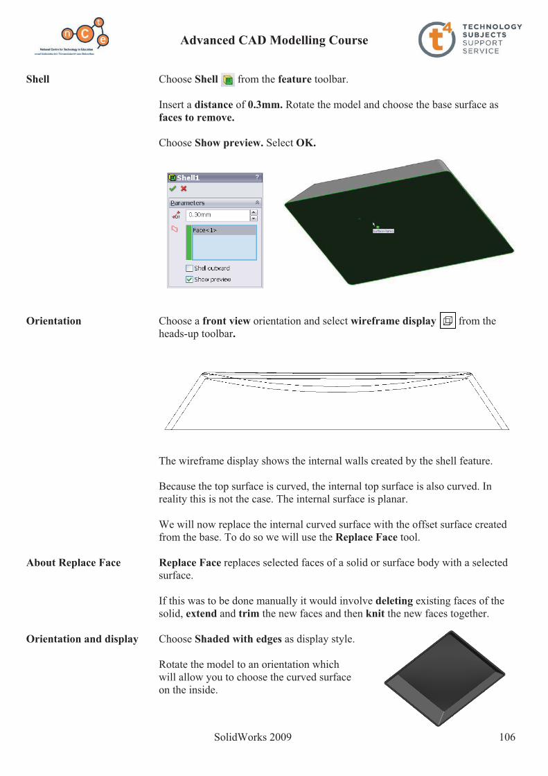
Advanced CAD Modelling Course
SolidWorks 2009 106
Shell Choose Shell from the feature toolbar.
Insert a distance of 0.3mm. Rotate the model and choose the base surface asfaces to remove.
Choose Show preview. Select OK.
Orientation Choose a front view orientation and select wireframe display from the heads-up toolbar.
The wireframe display shows the internal walls created by the shell feature.
Because the top surface is curved, the internal top surface is also curved. In reality this is not the case. The internal surface is planar.
We will now replace the internal curved surface with the offset surface created from the base. To do so we will use the Replace Face tool.
About Replace Face Replace Face replaces selected faces of a solid or surface body with a selected surface.
If this was to be done manually it would involve deleting existing faces of the solid, extend and trim the new faces and then knit the new faces together.
Orientation and display Choose Shaded with edges as display style.
Rotate the model to an orientation which will allow you to choose the curved surface on the inside.

Advanced CAD Modelling Course
SolidWorks 2009 107
Replace Face Choose Replace Face from the surfaces toolbar.
Select the curved surface of the model as the target face for replacement
Highlight the selection box for Replacement Surfaces. Expand the feature manager design tree in the graphics area and choose Surface-Offset2.
Choose OK
Orientation Choose a front view orientation and select wireframe display from the heads-up toolbar.
The top surface inside is no longer curved.It has been replaced by a flat planar surface.
Orientation and display Choose Shaded with edges as display style. Select an Isometric View.
Adding text The final stage in completing the exercise is to add the letter ‘J’ to the curved surface of the button.
In order to do so we must first create a sketch, of the letter, on the top plane.
We will then extrude the letter between the offset face and the top face of the button.

Advanced CAD Modelling Course
SolidWorks 2009 108
Creating the sketch Create a sketch on the Top plane. Choose Top View.
Centreline Sketch a horizontal Centreline andSmart dimension as shown.
Add Relation Add a Vertical Relation between the endpoint of the line and the origin.
Text Choose Text from the sketch toolbar.
Select the centreline sketch as the guide.
Enter ‘J’ as TEXT
Note the preview in the graphics area. You may have to use Flip Vertical or Flip Horizontalto orientate the text correctly.
Deselect Use document Font and select
Choose the settings displayed below.
Choose OK. Choose OK Exit the sketch.
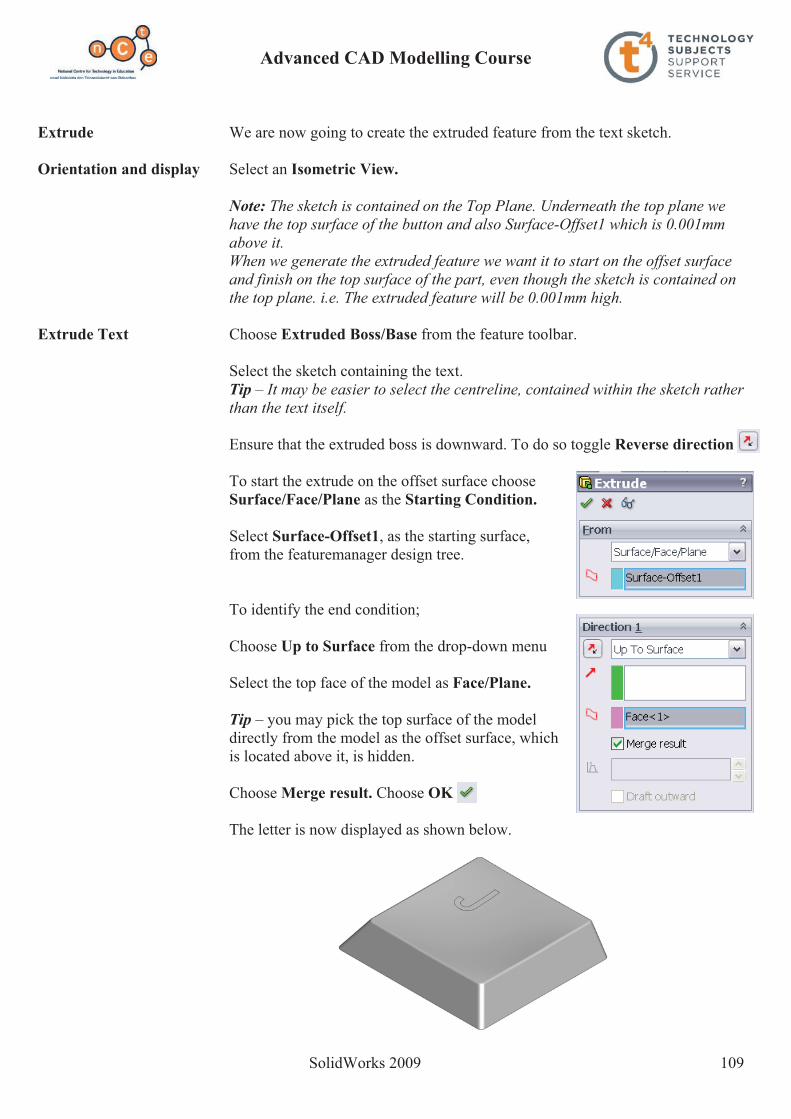
Advanced CAD Modelling Course
SolidWorks 2009 109
Extrude We are now going to create the extruded feature from the text sketch.
Orientation and display Select an Isometric View.
Note: The sketch is contained on the Top Plane. Underneath the top plane we have the top surface of the button and also Surface-Offset1 which is 0.001mm above it. When we generate the extruded feature we want it to start on the offset surface and finish on the top surface of the part, even though the sketch is contained on the top plane. i.e. The extruded feature will be 0.001mm high.
Extrude Text Choose Extruded Boss/Base from the feature toolbar.
Select the sketch containing the text. Tip – It may be easier to select the centreline, contained within the sketch rather than the text itself.
Ensure that the extruded boss is downward. To do so toggle Reverse direction
To start the extrude on the offset surface choose Surface/Face/Plane as the Starting Condition.
Select Surface-Offset1, as the starting surface, from the featuremanager design tree.
To identify the end condition;
Choose Up to Surface from the drop-down menu
Select the top face of the model as Face/Plane.
Tip – you may pick the top surface of the model directly from the model as the offset surface, which is located above it, is hidden.
Choose Merge result. Choose OK
The letter is now displayed as shown below.
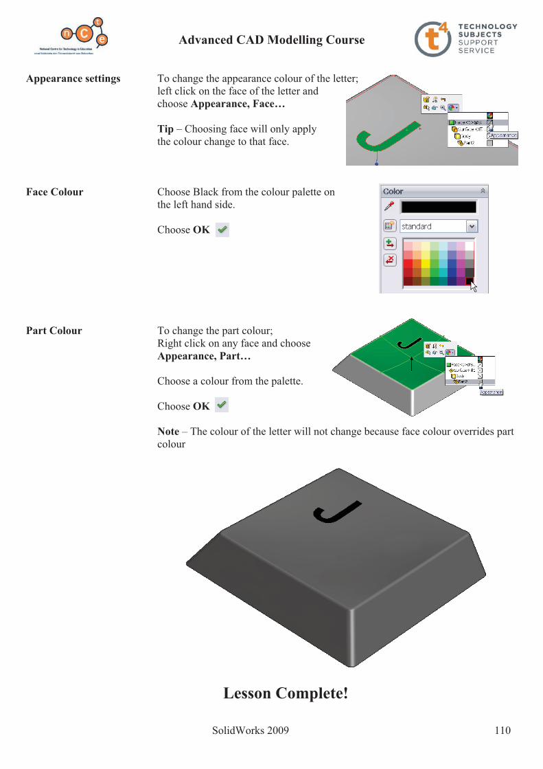
Advanced CAD Modelling Course
SolidWorks 2009 110
Appearance settings To change the appearance colour of the letter; left click on the face of the letter and choose Appearance, Face…
Tip – Choosing face will only applythe colour change to that face.
Face Colour Choose Black from the colour palette on the left hand side.
Choose OK
Part Colour To change the part colour; Right click on any face and choose
Appearance, Part…
Choose a colour from the palette.
Choose OK
Note – The colour of the letter will not change because face colour overrides part colour
Lesson Complete!

Advanced CAD Modelling Course
SolidWorks 2009 111
Prerequisite knowledge To complete this model you should have a working knowledge of Solidworks 2006/2009.
Focus of lesson This lesson focuses on using the following Surfaces tools: Filled Surface, Surface Thicken, Surface Offset as well as the usual sketch and feature Tools.
Introduction We will begin with the hat section of the baseball cap. First let us explore the geometry of the hat section. This will be created using a surface fill based on an elliptical profile and three guide curves as shown below.
Profile: this ellipse forms the boundary of the surface and is drawn on the Top Plane.
Guide Curve 1: drawn on the FrontPlane. Its endpoints are coincidentwith the major and minor axes of the profile ellipse.
Guide curves 2 & 3:drawn on planes which will be defined using the 60 degree lines and the verticalcentreline.
Once the profile and guide curves are drawn, the Surface Fill tool is used to generate the hat section.
Baseball Cap
Guide curve1
Guide curve 2
Guide curve 3
Profile

Advanced CAD Modelling Course
SolidWorks 2009 112
Sketch 1 We begin by creating a sketch on the Top Plane.
Creating the Sketch the two centrelines shown, which will Base Profile act as the major and minor axes of the Of the profile ellipse.Smart Dimension as indicatedBaseball cap and make the midpoints of both coincident
with the Origin.
From the sketch toolbar select ellipse. Make the centre of the ellipse coincident with the Origin and make the ends of the major axis
coincident with the ends of the horizontal centreline. Drop the ends of the minor axis
beyond the ends of the vertical centreline. (If youwere to drop the ends of the minor axis onto these points, the automatic coincident relations will not be added). We have to apply this coincident relation manually.
If it is decided to change the dimensions of the centrelines, the major and minor axes will automatically update to reflect this.
Sketch the centreline shown with the relations applied. Smart dimension the angle indicated. These lines will be used in the setting up of planes to contain
guide profiles for the body of the cap.
Mirror the 60 degree centreline about the major axis as shown.
Mirror both of these lines now about theminor axis. Note the automatic relations.
Should we decide to change the angle, or thedimensions of the ellipse these lines will automatically reflect these changes because of the relations applied.
Confirm the sketch.
Sketch 2 Create a sketch on the Front Plane.Guide curve If the length of the base of the cap from front is changed, the curve forming the profile to back from front to back will need to update to
reflect this change. In order for this to happen we will use the centreline(major axis) from sketch 1.

Advanced CAD Modelling Course
SolidWorks 2009 113
Convert Choose an isometric view, select the major axis, Entities select convert entities from the sketch toolbar.
N.B. The line will revert to a solid line so it must be changed back to a construction line, use the property manager.
Choose a front view. Draw the centreline and smart dimension as shown.
Draw the ellipse with the endpoints of themajor axis coincident with the ends of the horizontal centreline. As with sketch 1 – manually apply the relation afterwards.
Trim Trim the sketch to form the semi-ellipse shown. This curve will be the profile of the baseball cap from front to back.
Confirm the sketch.
Side profiles The profiles for the sides of the baseball cap are needed to give the cap the required shape. Were we to form the surface without them, it would end up rather spoon shaped! The profiles will be drawn on two separate planes, which will be set up using the 60 degree lines from sketch 1 and the endpoint of the 100mm vertical line from sketch 2.
Insert Plane Select reference geometry, plane. Choose the following selections.
Choose OK.
Sketch 3 Create the sketch on this plane in the same fashion used for sketch 2. Use convert entities
Hide Hide plane 1 when the sketch is completed.
Sketch 4 Repeat the process to complete sketch 4.
Filled Surface Select Filled Surface from the Surfaces toolbar.
Use sketch1 as the patch boundary. As can be seen from the graphic, this is basically a planar surface.
Select sketches 2,3 and 4as the guide curves.These curves will define the curvature of the surface we require.
The patch boundary acts like a cutting plane as it trims off the excess surface created bythe guide curves.

Advanced CAD Modelling Course
SolidWorks 2009 114
Select OK.
Rename Feature Rename the feature as Hat Section.
Rotate If the Hat Section is rotated and viewedfrom underneath it can clearly be seen that it has no thickness.
Surface Thicken To give the Hat Section a thickness,select Thicken from the surfaces toolbar.
Select the Hat Section as the surface to thicken.
Select 2mm as the thickness.
Select Thicken Side 1 so that the surface thickens towards the inside of the hat to keep the dimensions of the outer surface unchanged.
Creating the Stitching In order to create the stitching effect we will sweep a semicircular profile along the existing guide curves. We will also use the intersection of these guide curves with the base of the hat section as coincident points for to create the profile of the stitching.
Sketch We will begin by creating the semi-circular profile
sketch on the Top Plane.Choose to show sketch1. Choose a Normal To view.
Make the centre point of the circle coincident with the intersection point as shown.
Use Convert Entities to use the ellipse to trim the circle.
Smart Dimension to diameter 1mm.
Confirm the sketch.
Stitching 1 To create the stitching, select Swept Boss/Base from the Features menu. In order to create
the sweep a profile and a path are required.Use sketch 5 as the profile. Select sketch 4 as the pathalong which the profile will travel.
Select OK.
Rename Feature Rename the feature as Stitching1.
You will now notice an open hand under sketch 4in boththe Hat Section and the Stitching. This indicates that the sketch is being shared by two features. If the dimensions of the hat section are changed the stitching willautomatically update as a result of this selection.

Advanced CAD Modelling Course
SolidWorks 2009 115
Stitching 2 Repeat this process for Stitching 2. First create the sketch of the semi-circle with its centre point
coincident with the intersection of sketch3 and sketch1.
Smart Dimension to diameter 1mm.
Use Convert Entities to use the ellipse to trim the circle.
Confirm the sketch.
Stitching 2 To create the stitching, select Swept Boss/Base from the Features menu. In order to create the sweep a profile and a path are required. Use sketch 6 as the profile. Select sketch 3 as the path along which the profile
will travel.
Select OK.
Rename Feature Rename the feature as Stitching2.
Creating the In order to create the button feature on top of the cap we need to set up a plane Button on which to create the sketch, as we can’t sketch on the surface of the cap. By
creating the sketch on this plane, it can then be extruded to the surface of the cap.
Insert Plane Choose Plane from the Reference Geometry commands on the Features menu.
Choose Top Plane as the first Reference.
Set the distance as 102mm. This puts the plane 2mm above the highest point ofthe hat section.
Reverse direction as required.
Select OK.
Sketch Create the sketch shown on Plane 3. The centre of the circle is coincident with the
Origin.
Confirm the sketch.
Extrude Select Extrude from the Features menu.
Make the following selections:

Advanced CAD Modelling Course
SolidWorks 2009 116
For direction 1 choose Up to Surface.
Select any one of the outer faces of the hat section. This will cause the extrusion to stop when it reaches this surface.
Select OK.
Rename Feature Rename the feature as Button.
Hide Hide Plane 3.
Rear Hole In order to create the rear hole cut on the back of the cap, once again we will have to create the sketch on a plane and extrude cut up to the surface as we can’t sketch on the curved surface.
Create this sketch on the Right Plane, making the centre of the circle coincident with the origin.
Sketch a horizontal line and smart dimension as shown.
Using the Trim command trim the ends of the line and the circle.
Confirm the sketch.
From the Features menu select Extruded Cut.
Set the end condition to through all to ensure that the cut passes through the entire hat structure.
Flip direction as required, to make sure that the cut is made to the rear.
Select OK.
Rename Feature Rename the feature as Rear Hole.
Adjustment Strap The adjustment strap of a baseball cap is usually made from a different material to that of the cap. We already have the strap drawn as part of the hat section. We can use the Split line tool to separate the strap section from the hat surface, and apply a different appearance to the strap. The Split Line tool projects an entity (sketch, solid, surface, face, plane, or surface spline) to surfaces, or curved or planar faces. It divides a selected face into multiple separate faces.

Advanced CAD Modelling Course
SolidWorks 2009 117
Sketch We must first create a sketch to use as the line for the Split line command.
Take a Left View to enable us to view the rear hole of the Hat Section.
Create the sketch shown opposite on the Right Plane, Having its centre on the Origin and making the
circumference of the circle coincident with the point indicated.
Confirm the sketch.
Split Line Select Curves, Split Line, from the Features menu.
Under Type of Split select projection; as we wantto project the sketch onto the curved surface to create the split.
Make the following selections :
Sketch 9 as the sketch to project
Face 1 as the face to split.
Select OK.
Rename Feature Rename the feature as Adjustment Strap Outside.
Appearance It appears as though nothing has changed because we don’t see a line appearing to separate the two surfaces, so for clarity we will add a colour to the strap portion.
Select the strap portion as shown and select the Appearance option.
Select Face<1>@Adj...
Make the followingcolour selection.
The division of the surfaces is now much clearer.
Adjustment Strap The procedure is repeated for the inside surface of Inside adjustment strap.
Select Curves, Split Line, from the Features menu.
Under Type of Split select projection; as we wantto project the sketch onto the curved surface to create
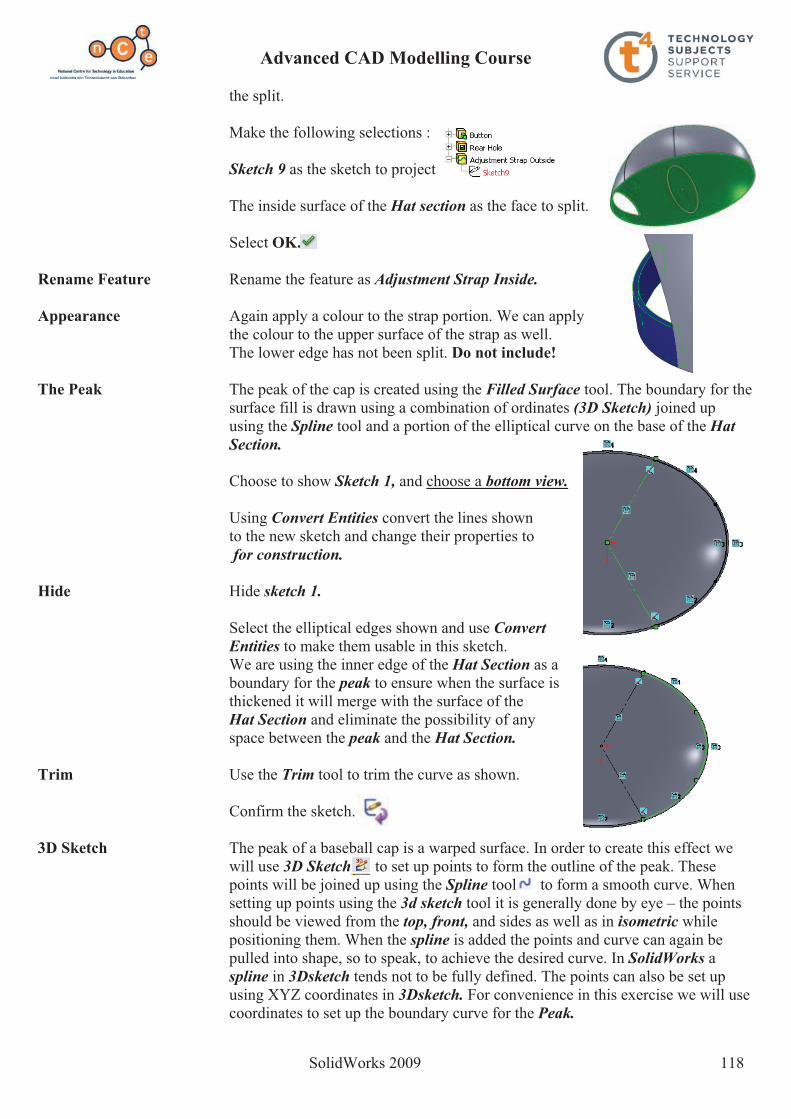
Advanced CAD Modelling Course
SolidWorks 2009 118
the split.
Make the following selections :
Sketch 9 as the sketch to project
The inside surface of the Hat section as the face to split.
Select OK.
Rename Feature Rename the feature as Adjustment Strap Inside.
Appearance Again apply a colour to the strap portion. We can apply the colour to the upper surface of the strap as well. The lower edge has not been split. Do not include!
The Peak The peak of the cap is created using the Filled Surface tool. The boundary for the surface fill is drawn using a combination of ordinates (3D Sketch) joined up using the Spline tool and a portion of the elliptical curve on the base of the HatSection.
Choose to show Sketch 1, and choose a bottom view.
Using Convert Entities convert the lines shown to the new sketch and change their properties to
for construction.
Hide Hide sketch 1.
Select the elliptical edges shown and use ConvertEntities to make them usable in this sketch. We are using the inner edge of the Hat Section as a
boundary for the peak to ensure when the surface is thickened it will merge with the surface of theHat Section and eliminate the possibility of any space between the peak and the Hat Section.
Trim Use the Trim tool to trim the curve as shown.
Confirm the sketch.
3D Sketch The peak of a baseball cap is a warped surface. In order to create this effect we will use 3D Sketch to set up points to form the outline of the peak. These points will be joined up using the Spline tool to form a smooth curve. When setting up points using the 3d sketch tool it is generally done by eye – the points should be viewed from the top, front, and sides as well as in isometric while positioning them. When the spline is added the points and curve can again be pulled into shape, so to speak, to achieve the desired curve. In SolidWorks aspline in 3Dsketch tends not to be fully defined. The points can also be set up using XYZ coordinates in 3Dsketch. For convenience in this exercise we will use coordinates to set up the boundary curve for the Peak.

Advanced CAD Modelling Course
SolidWorks 2009 119
From the Sketch menu select 3D Sketchto activate the tool.
Now select the Point command. Select an isometric view and position the seven random points as illustrated.
Note these points are dropped in randomly for the present. We will apply XYZ values to correctly position them.
As can be seen from the orthographic views the points are randomly positioned but are forming a rough outline of the peak.
XYZ Values To apply the coordinates to the points we will use the values outlined in the table across.
Working from left to right apply the XYZ values to each of the points in turn.
Select the first point by left clicking on it.
Fill in the values for the first point from the table.
Use the TAB key to move between the XYZ value boxes.
Repeat the process for each of the points.
3D Spline Select spline from the Sketch menu.
Start the spline on the intersection of the construction line and elliptical curve of Sketch 10. We want the spline to start here so that when the surface is created and thickened it will merge with the surface of theHat Section and eliminate the possibility of any space between the peak and the Hat Section.
Continue to join up the points with the spline tool taking care to complete the curve in one go.
Finish the spline (Right click and choose end spline) at the intersection of the other construction line andelliptical curve of Sketch 10.
Confirm the sketch.
X� Y� Z�100� -15 90160� -20 75 185� -15 45195� -10 0 185� -15 -45160� -20 -75 100� -15 -90
Wireframe used for visibility

Advanced CAD Modelling Course
SolidWorks 2009 120
Filled Surface From the Surfaces menu select the Filled Surface tool. The Filled Surface toolconstructs a surface patch with any number of sides, within a boundary defined by existingmodel edges, sketches, or curves,including composite curves.
Select 3DSketch 1 and sketch 10as the patch boundaries.
Select OK.
We have now created the under-surface of the baseball cap peak.
Rename Feature Rename the feature as Peak.Surface Thicken To give the Peak some depth we will use Thicken from the surfaces menu.
Select the Peak asthe surface to thicken.
Set the thickness to 2mm.
Choose to thicken side 2 as This will ensure that the Surface of the peak thickens
towards the hat section.
Select OK.
Rename Feature Rename the feature as Thicken Peak.
Nike Logo To create the Nike logo on the peak of the cap we will have to set up the sketch on a plane or planar surface as we can’t create a sketch on a curved or warped surface. The top surface of the logo must also run parallel to the top surface of the peak – as it sits on the peak of the cap. To satisfy this condition we will set up a surface offset. By doing this the extrusion can begin at the offset surface and endat the top surface of the peak.
Offset Surface Select Offset Surface from the surfaces menu.
Choose the top surface of the Peak as theSurface or face to offset.
Set the thickness to 0.3mm.
Select OK.

Advanced CAD Modelling Course
SolidWorks 2009 121
Sketch Create the sketch shown on the Top Plane.
Smart dimension the sketch as shown. Note the automatic relations.
Confirm the sketch.
The sketch has been created on the Top Plane but will be used to create the extrusion from the Surface Offset to the top surface of the Peak.
Extrude Select Extrude boss/base from the features menu.
Select sketch 11 as the sketch to use for the extrusion. Make the following selections:
Set the start condition as Surface/face/plane
Choose surface – offset1 as the start point.
Change the direction of the extrusion so that It is extruding towards the top surface of the
Peak.
Set the end condition as up to next.
Select OK.
Rename Feature Rename the feature as Nike Logo.
Hide Hide Surface-Offset1.
Fillet Apply a fillet of 0.2mm to the top edgesof the logo.
Rename Feature Rename the feature as Logo Fillet.
Fillet Apply a fillet of 0.5mm to the top edge ofthe peak.
Rename Feature Rename the feature as Peak Fillet.
Fillet Apply a fillet of 0.75 to the top edge of the button.
Rename Feature Rename the feature as Button Fillet.

Advanced CAD Modelling Course
SolidWorks 2009 122
Surface Offset In order to put the NIKE text across the frontof the hat section we again have to set up aSurface Offset as we can’t create a sketch on the curved surface.
From the Surfaces menu select surface offset as before.
Choose the front of the hat section as the surface to create the offset from.
Set the offset distance to 0.25mm.
Select OK.
Sketch Create the sketch shown on the Right Plane. Apply a vertical relation betweenthe midpoint of the centreline and theorigin.
Smart dimension as shown.
Text Choose Text from the sketch menu.
Make the following selections:
Choose the centreline as the line for the text to follow.
Select Arial as the Font.
Set the Font Style to Bold Italic.
Set the units to 35mm.
Select OK.
Confirm the sketch.
Extrude Select Extrude boss/base from the features menu.
Select sketch 12 as the sketch to use for the extrusion. Make the following selections:
Set the start condition as Surface/face/plane
Choose surface – offset 2 as the start point.
Change the direction of the extrusion so that It is extruding towards the front surface of the
Hat section.

Advanced CAD Modelling Course
SolidWorks 2009 123
Set the end condition as up to next.
Select OK.
Rename Feature Rename the feature as Nike Text.
Hide Hide surface – offset 2.
Apply Material Under fabrics choose Blue Cotton as the material. Apply it to the body of the hat section.
Apply Colour Select the colour shown across as the colour for the NIKE text and the logo. Make sure the colour is applied to the fillets on the logo as well.
Exercise complete!
Having�completed�the�exercise�it�is�worth�
noting�the�initial�positioning�of�the�origin�and�
the�subsequent�usefulness�of�the�origin�and�
reference�planes�in�completing�the�exercise.�

Advanced CAD Modelling Course
SolidWorks 2009 124
Creation of Photorealistic Images PhotoWorks & PhotoView 360

Advanced CAD Modelling Course
SolidWorks 2009 125
PhotoWorks - iPhone
Prerequisite knowledge A basic knowledge of SolidWorks 2009 is required.
Focus of Lesson This lesson will focus on using PhotoWorks, as part of the SolidWorks program, to generate photorealistic images from a SolidWorks file.
Note These notes are created using a SolidWorks part file, however, the same principles apply in creating a photorealistic image from an assembly.
Getting Started PhotoWorks is integrated into SolidWorks 2009 much more so than 2006. Appearances and scenes are applied in the SolidWorks graphics area and are used
in PhotoWorks to generate the photorealistic image. PhotoWorks PhotoWorks is an add-in of SolidWorks, therefore we must add in the program
to begin.
Choose Tools, Add-ins.
Click on PhotoWorks as an Add in.
If you want PhotoWorks to appear as an add-in each time you launch SolidWorks; check Start Up
Open file Copy the folder called iphone from the CD to your computer. Open the part called iphone from the iphone folder.

Advanced CAD Modelling Course
SolidWorks 2009 126
PhotoWorks can now be accessed in theOffice Products tab in Solidworks
Appearances Because the iphone is predominantly black in colour, we will add a black appearance to the entire part.
Left click on any of the faces of the iphone And choose appearance from the pop-up menu.
The hierarchy of application of appearances is displayed.
Face, Feature, Body or Part
Remember; An appearance applied to a face will override that applied to a feature, which will override that applied to a part…
Black appearance A default appearance has been applied to the part on creation. Click into the square next to the part name – iphone.
(An indicates that no appearance has been applied)
The appearances palette is displayed in the task pane.

Advanced CAD Modelling Course
SolidWorks 2009 127
The appearances are displayed in a tree like format.
We wish to apply a black appearance to the part. Expand the tree to locate:
Miscellaneous, Studio materials, Dark room wall
Drag and drop the appearance onto the model. Choose OK.
The appearance is applied to the entire part because the part was preselected from the hierarchy tree.
Silver trim We will now apply a silver appearance to a number of features of the iphone
The following image shows the Hierarchy of appearances
The face will override the feature, The feature overrides the body
The body overrides the part.
The black appearance we have applied to the entire part will be overridden by a different appearance should we apply it to a face, feature or body
Left click on the top face fillet from the featuremanager design tree.
Choose Appearance and select next to top face fillet, as shown.
Choose Metal, Silver, Polished Silver from the appearances palette in the task pane.
Choose OK.Multiple Selections We can apply this appearance to multiple features at the same time using the
feature manager design tree.

Advanced CAD Modelling Course
SolidWorks 2009 128
Whilst holding down control, select each of the following features;
control button, power button, mute button, volume control,volume space, fillet volume, volume button 2 filletand connection port 2
Release Ctrl and choosethe next to the features in the hierarchy display.
Choose Metal, Silver,Polished Silver from the appearances palette in the task pane.
Choose OK.
The appearance will be applied to all of the preselected features and will override the black appearance applied to the entire part.
Speakers Apply Fabric, Carpet, Carpet colour 4 to the two speakers andthe ear space, in the same way.
Decal The ability to apply a decal is one defining aspect that is different between PhotoView 360 and PhotoWorks. You can only apply a decal in PhotoWorks.

Advanced CAD Modelling Course
SolidWorks 2009 129
A decal is any digital image that can be manipulated into being on a face of a solidworks object. (BMP – bitmap files work best)
We are going to apply the iphone interface decal located in the iphone folderonto the screen of the iphone.
Applying decal Choose PhotoWorks, decal and browse to find thehomescreen iphone(located in the iphone folder)
Select the face on which we want the decal to bePositioned.
Mapping Image We now have to map the digital image to the screen to ensure it fits the screen correctly
Select Mapping tab in the left window.
Ensure that the map is set as label.
Ensure the angle of the decal is correct.
Use the angle adjustments to ensure it fits correctly.
Size/Orientation
Fit to width and fit to height.
You may need to mirror horizontally or vertically.
Choose OK..

Advanced CAD Modelling Course
SolidWorks 2009 130
Scene Choose PhotoWorks, Scene.
Choose the desired scene. Choose Apply.
Alternatively the scene may be draggedand dropped from the task pane or selected from the heads up toolbar.
Render Once the scene has been selected it must be rendered to see the image.
Before rendering orientate the model and zoom in or out to position the required view. Whatever is displayed on screen is what will be captured in the photorealistic image.
Choose PhotoWorks, Render.
Save the file To save the file choose File, Save as. Save the model in the iphone folder in an appropriate file format, JPEG being the most common.
When the model is moved or rotated the rendered model will disappear.
Render to File Alternatively you may choose PhotoWorks, Render to File. This will create the jpeg image file without producing a rendered image on screen.

Advanced CAD Modelling Course
SolidWorks 2009 131
Photoview 360 – Creating Photorealistic Images
Prerequisite knowledge A basic knowledge of SolidWorks 2009 is required.
Focus of Lesson This lesson will focus on using PhotoView 360 to create photorealistic images from SolidWorks models.
PhotoView 360 PhotoView 360 is a software package, separate to SolidWorks, which generates digital lifelike images (photorealistic images) from SolidWorks files. PhotoView 360 is an easy and quick way to produce high quality photorealistic images.
There are a wider range of appearances in PhotoView 360 than in SolidWorks.
Getting Started PhotoView 360 is a separate program which loads with SolidWorks 2009.
To launch the program; double click on the PhotoView 360 icon located on the desktop.
PhotoView 360 allows you to import a SolidWorks part or assembly and apply particular appearances and scenes to that file.

Advanced CAD Modelling Course
SolidWorks 2009 132
The Interface When using PhotoView 360 we work from left to right on the main menu.
1. Open file (Import SolidWorks File) 2. Apply appearances 3. Apply Environment 4. Edit settings 5. Final render, save file
The main menu is shown below;
Toolbars There are four options when applying an appearance – you may choose to apply an appearance to an entire assembly, single part, body of a part or an individual face.The appearance will be applied based on whichever option is pre-selected.
There is a second toolbar under the main toolbar. Its function is to move and rotate the model to enable the user to choose particular faces, features or parts as well as positioning the model to capture the photorealistic image.
The roller ball of the mouse can be used to maneuver a solid in Photoview 360window in the same way as SolidWorks.
The select icon must be highlighted in order to apply appearances to any aspect of the SolidWorks model.

Advanced CAD Modelling Course
SolidWorks 2009 133
Transfer Folder Copy the folder named Photoview 360 from the CD onto your computer.
Open File Open the assembly named Skateboard located in the folder Photoview 360. The parts and assembly were created in SolidWorks using the default material appearance.
When you open a SolidWorks file in PhotoView 360, any appearances applied in SolidWorks will be displayed. However, there are enhanced appearances available in PhotoView 360 and it is recommended that these are applied to achieve better results.
Use the open file button and open the skateboard assembly.
Rotate and Pan Practice moving and rotating the model using the various tools in the navigation toolbar.
Highlight the command, move to the graphics area, manipulate the positioning of the model.
Applying appearances We are going to apply appearances to each individual part of the model.
Appearances A wooden finish is to be applied to the board of the skateboard.
Highlight the part icon in the selection toolbar.
Ensure that select is highlighted in the navigation toolbar.
Adding Appearance Click on appearances button in the main toolbar.
The Presets window will appear. Click on the triangle next to the category name to expand or collapse the selection tree.
Navigate to Organic, wood, walnut.
Drag and drop polished walnut onto thedesired part in the graphics area.

Advanced CAD Modelling Course
SolidWorks 2009 134
Note: Because Part was preselected, the appearance is applied to the entire part not just the face onto which it was dropped.
Edit Appearance If you wish to change an appearance; drag and drop the chosen appearance onto the part and it will replace the existing one.
Wheels Employing the same procedure, apply a blue low gloss plasticappearance to any of the wheels of the skateboard.
Note: The remaining three wheels will also display that same appearance. This is because these are four occurrences of the same SolidWorks part – Wheel.
Bush Apply a green low gloss plastic appearance to the bushes.
Note: You will have to rotate the model in order to access the bush to drop the appearance onto it.
Hex Bolt Apply a polished brass appearance to the Hex Bolts and nuts(Bolts and nuts joining the board to the bearing)
Steel elements All other parts are to have machined steel appearance applied.

Advanced CAD Modelling Course
SolidWorks 2009 135
Face appearance All appearances applied thus far have been applied to entire parts. We can also constrain an appearance to be applied to a particular face of a part.
Just as in SolidWorks, a hierarchy exits when applying appearances within PhotoView 360. A face appearance will override an appearance which has been applied to an entire part.
Wheel face We will apply an appearance to the face of the wheel to enhance the model.
Pre-select face on the selection toolbar.
Navigate to red high gloss plastic in the Presets window.
Drag and drop the appearance onto the face of the wheel. Just as before this appearance will be applied to the faces of the four wheels.
Top of skateboard Choose an appropriate appearance for the top face of theskateboard
Plastic, Composite, Carbon Fiber Inlay Unidirectional
Environments Environments can be looked upon as backdrops and can be applied in a similar manner as the appearances are applied to faces or parts.
Select environments in the main menu. The Environments selection box appears.
Drag and drop the chosen environment into the graphics area.
Alternatively double click on the desiredenvironment.
Dragging and dropping an alternative environment will override the previous selection.

Advanced CAD Modelling Course
SolidWorks 2009 136
The above are examples of environments that can be applied.
Apply a daytime environment.
Positioning Capturing a good photorealistic image can be compared to setting up a camera for taking a photo.
Use the navigation tools to orientate the model so that it fills the majority of the display window and shows good detail of the solid.
Settings for rendering Settings allows us to set the format in which our image will be saved along with the quality of the image.
Open settings option from main menu
Environment properties
Adjust Ground Plane height; Sets the floor height of the environment in relation to the model. Decreasing this number moves the floor down, increasing the number moves the floor up, closer to the model.
Rotate Environment:Rotates the environment in relation to the model. This will affect lighting, shadow and shade etc.
Gamma: corrects the output to compensate for the output device ie a printer or monitor.Image Output Resolution – changes the number of pixels in the final rendering. Increased number of pixels, increases files size and rendering time.
Image output Presets – height and width may be chosen or choose a preset value. 640 x 480 is suitable or an A3 size output.
Default Image File Format – JPEG, BMP, etc Render – good, better, best, max
The higher the quality of the render, the longer the time it takes to complete the render.
A better quality image is sufficient to complete this exercise but sample the other quality images also.

Advanced CAD Modelling Course
SolidWorks 2009 137
Once the type of render is selected a new window opens with the selected options applied
Render The render is now complete and a JPEG file can be created from this window.
Save the image as Skateboardin the PhotoView 360 folder.
Once rendered, the image will be allocated a number 1 – 9 as indicated above. Selecting that number will allow you to retrieve the image at a later stage, if required.
Add different environments and manipulate the positioning of the model to capture various images of the model.
Zoom and span to specific areas of the model to take photorealistic images of different components