Embed Size (px)
Citation preview
Advanced Cable-Stayed Bridge Construction Process Analysis with ANSYS/CivilFEM
Eduardo Salete Ingeciber, S.A., Univ. Politécnica de Madrid
János Néző Ingeciber, S.A. Javier Aparicio Ingeciber, S.A.
Abelardo Baños Ingeciber, S.A.
Emilio Baños - Ayuso Ingeciber, S.A.
Abstract This paper demonstrates how sophisticated computational techniques can help to understand better the behavior of cable-stayed bridges and what kind of tools are available for bridge engineers to handle even the most extreme situations.
Since one of the key elements in the success of this structural system lies in its construction method, the main focus of this paper is on the simulation of the free-cantilever construction process and the determination of cable forces during the phases of the erection in order to achieve the desired shape and internal force distribution in the final state of the structure. The paper, using ANSYS/CivilFEM, a software package developed for advanced civil engineering analyses, presents different numerical techniques (based on both linear and non-linear analysis) to determine the final state of the bridge and the backward process analysis to conduct a step-by-step analysis of the construction.
Finite Element Analysis can provide engineers with an overwhelming amount of data therefore the efficient presentation of results (postprocessing) is of outmost importance especially for such complex systems as cable-stayed bridges.
The paper also demonstrates how the flexibility of ANSYS/CivilFEM allows the users to find a sensible way to access all the necessary data and produce both text based and graphical outputs.
A typical example of a cable-stayed bridge is analyzed by the methods described in the paper and the results are presented using postprocessing techniques.
Introduction CivilFEM is a customization of the finite element analysis software ANSYS, which has the aim to approach the Civil Engineering World with the general purpose tools of ANSYS.
The structure of CivilFEM is made up of a main program, called CivilFEM Intro, onto which several specific modules of Civil Engineering applications can be added: Bridges, Prestressed Concrete and Geotechnics.
The first of these modules has utilities for modeling and analyze virtually any bridge types:
- Metallic bridges.
- Prestressed concrete bridges.
- Mixed or composite bridges.
With different types of supports:
- Simple supports.
- Suspension bridges.
- Cable-Stayed bridges.
- Arch bridges.
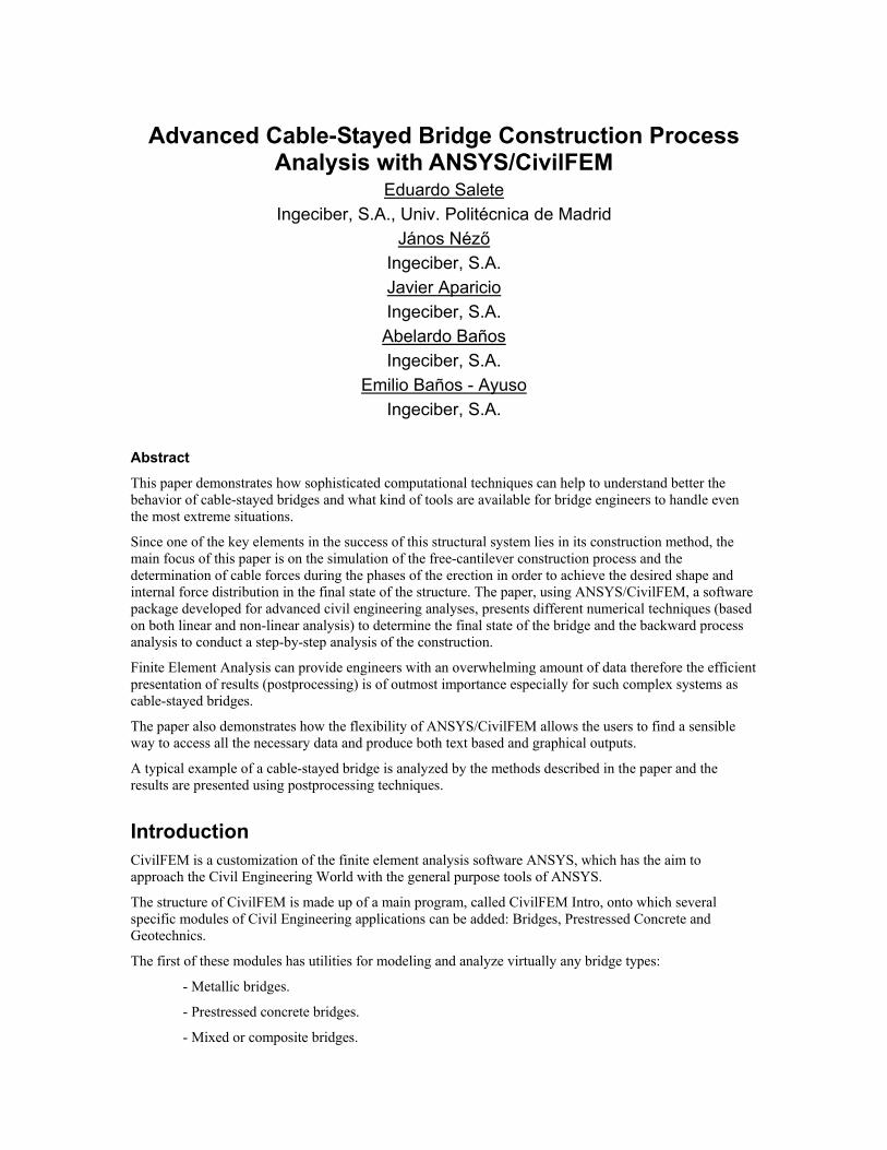
Figure 1. Bridge Sections
The help this system offers to the engineer starts with the definition of the layout of the bridge, in plan and elevation, using for the first one straight lines, circular arcs and clothoids, and parabolic arcs and straight segments for the second.
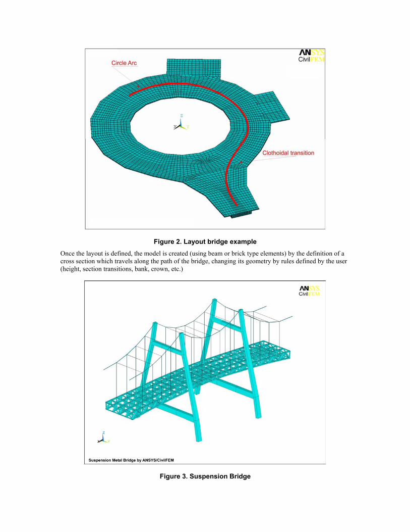
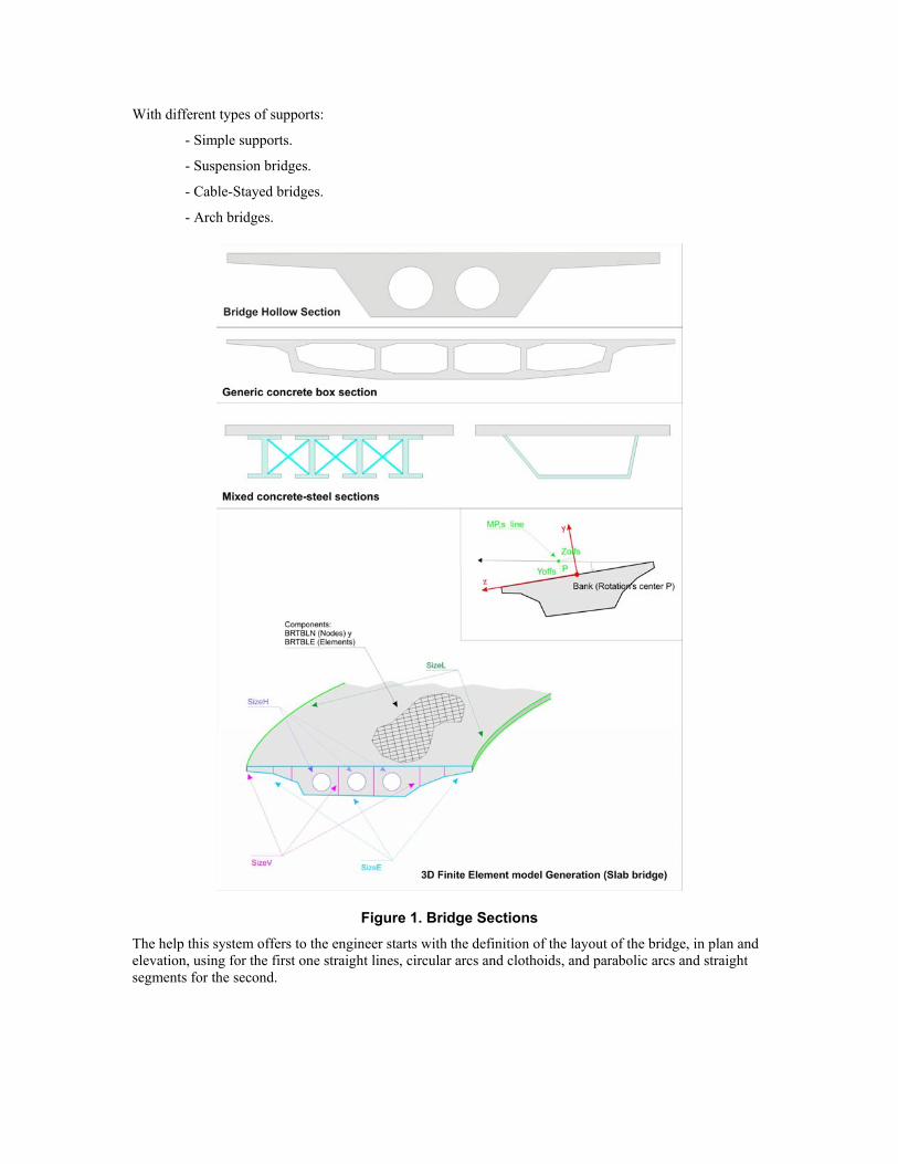
Figure 2. Layout bridge example
Once the layout is defined, the model is created (using beam or brick type elements) by the definition of a cross section which travels along the path of the bridge, changing its geometry by rules defined by the user (height, section transitions, bank, crown, etc.)
Figure 3. Suspension Bridge
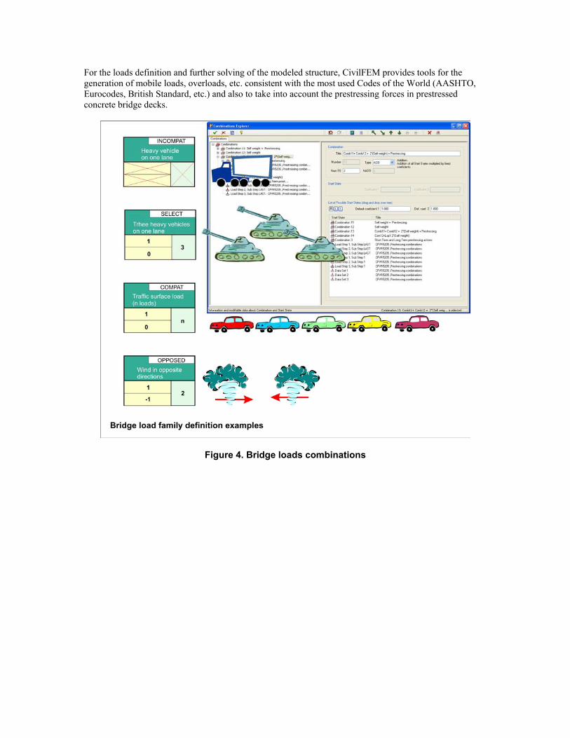
For the loads definition and further solving of the modeled structure, CivilFEM provides tools for the generation of mobile loads, overloads, etc. consistent with the most used Codes of the World (AASHTO, Eurocodes, British Standard, etc.) and also to take into account the prestressing forces in prestressed concrete bridge decks.
Figure 4. Bridge loads combinations
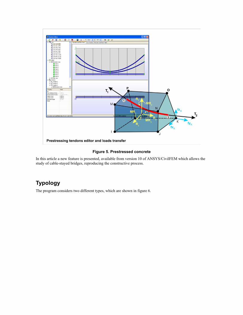
Figure 5. Prestressed concrete
In this article a new feature is presented, available from version 10 of ANSYS/CivilFEM which allows the study of cable-stayed bridges, reproducing the constructive process.
Typology The program considers two different types, which are shown in figure 6.
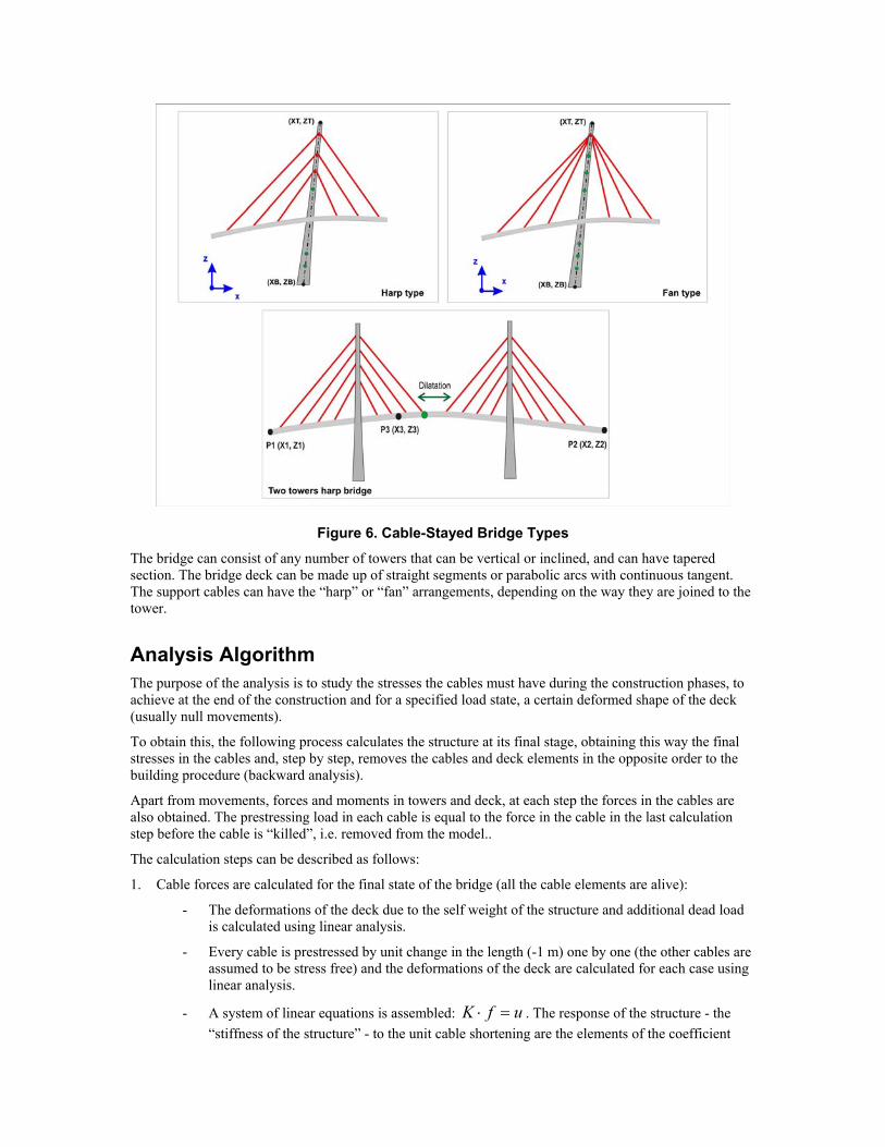
Figure 6. Cable-Stayed Bridge Types The bridge can consist of any number of towers that can be vertical or inclined, and can have tapered section. The bridge deck can be made up of straight segments or parabolic arcs with continuous tangent. The support cables can have the “harp” or “fan” arrangements, depending on the way they are joined to the tower.
Analysis Algorithm The purpose of the analysis is to study the stresses the cables must have during the construction phases, to achieve at the end of the construction and for a specified load state, a certain deformed shape of the deck (usually null movements).
To obtain this, the following process calculates the structure at its final stage, obtaining this way the final stresses in the cables and, step by step, removes the cables and deck elements in the opposite order to the building procedure (backward analysis).
Apart from movements, forces and moments in towers and deck, at each step the forces in the cables are also obtained. The prestressing load in each cable is equal to the force in the cable in the last calculation step before the cable is “killed”, i.e. removed from the model..
The calculation steps can be described as follows:
1. Cable forces are calculated for the final state of the bridge (all the cable elements are alive):
- The deformations of the deck due to the self weight of the structure and additional dead load is calculated using linear analysis.
- Every cable is prestressed by unit change in the length (-1 m) one by one (the other cables are assumed to be stress free) and the deformations of the deck are calculated for each case using linear analysis.
- A system of linear equations is assembled: ufK =⋅ . The response of the structure - the “stiffness of the structure” - to the unit cable shortening are the elements of the coefficient
matrix (K). The deformations (UY of the deck and UX of the tower top) are the elements of the vector on the right-hand side (u).
- The system of linear equations is solved and f is determined. The elements of the f vector are the actual cable shortening required to achieve the desired shape of the structure.
- The f vector is applied as cable shortening and the structure is solved again.
2. Nonlinear construction process analysis: backward analysis ('demolishing' the bridge step by step)
- Remove additional dead load.
- Remove the last section of the deck.
- Loop over the rest of the structure:
- remove one cable (kill cable element).
- remove one segment of the deck (kill deck element).
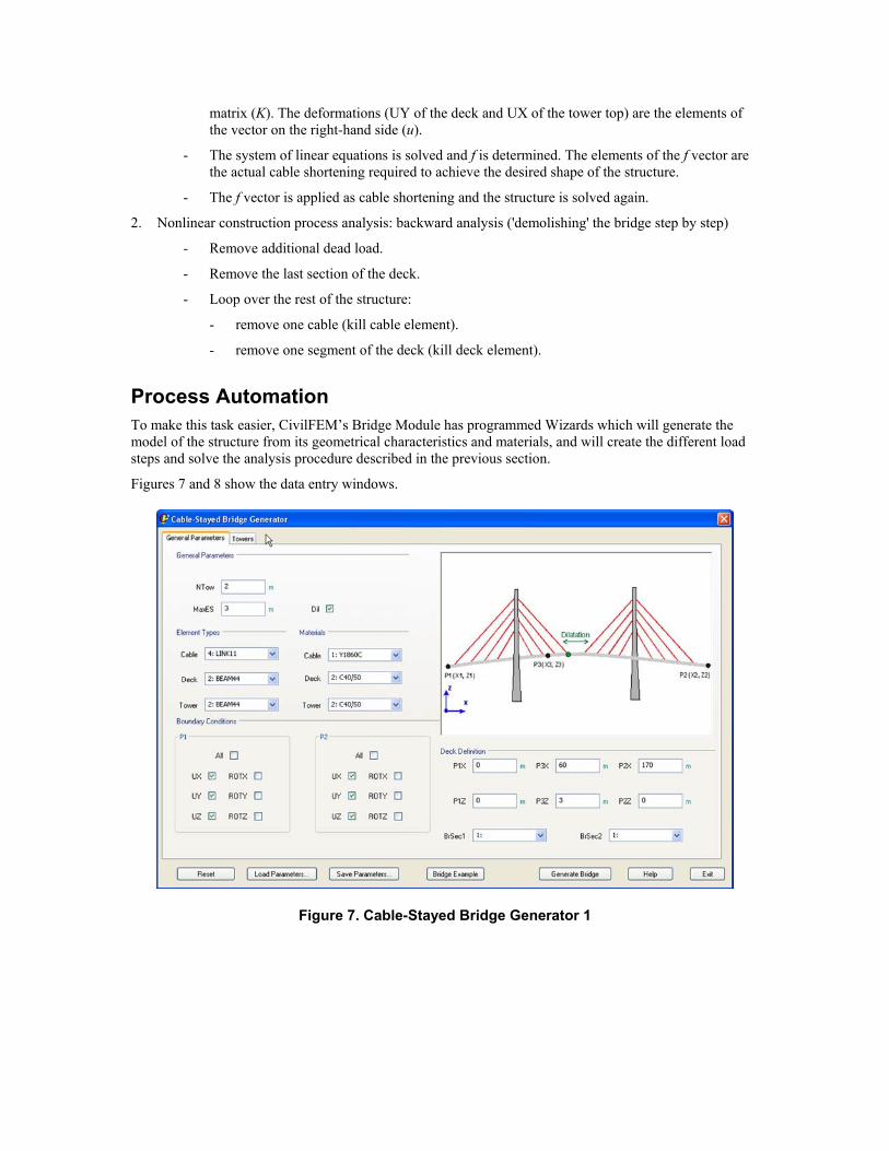
Process Automation To make this task easier, CivilFEM’s Bridge Module has programmed Wizards which will generate the model of the structure from its geometrical characteristics and materials, and will create the different load steps and solve the analysis procedure described in the previous section.
Figures 7 and 8 show the data entry windows.
Figure 7. Cable-Stayed Bridge Generator 1
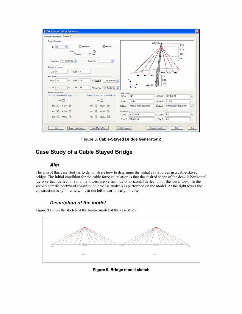
Figure 8. Cable-Stayed Bridge Generator 2
Case Study of a Cable Stayed Bridge
Aim The aim of this case study is to demonstrate how to determine the initial cable forces in a cable-stayed bridge. The initial condition for the cable force calculation is that the desired shape of the deck is horizontal (zero vertical deflection) and the towers are vertical (zero horizontal deflection of the tower tops). In the second part the backward construction process analysis is performed on the model. At the right tower the construction is symmetric while at the left tower it is asymmetric.
Description of the model Figure 9 shows the sketch of the bridge model of the case study.
Figure 9. Bridge model sketch
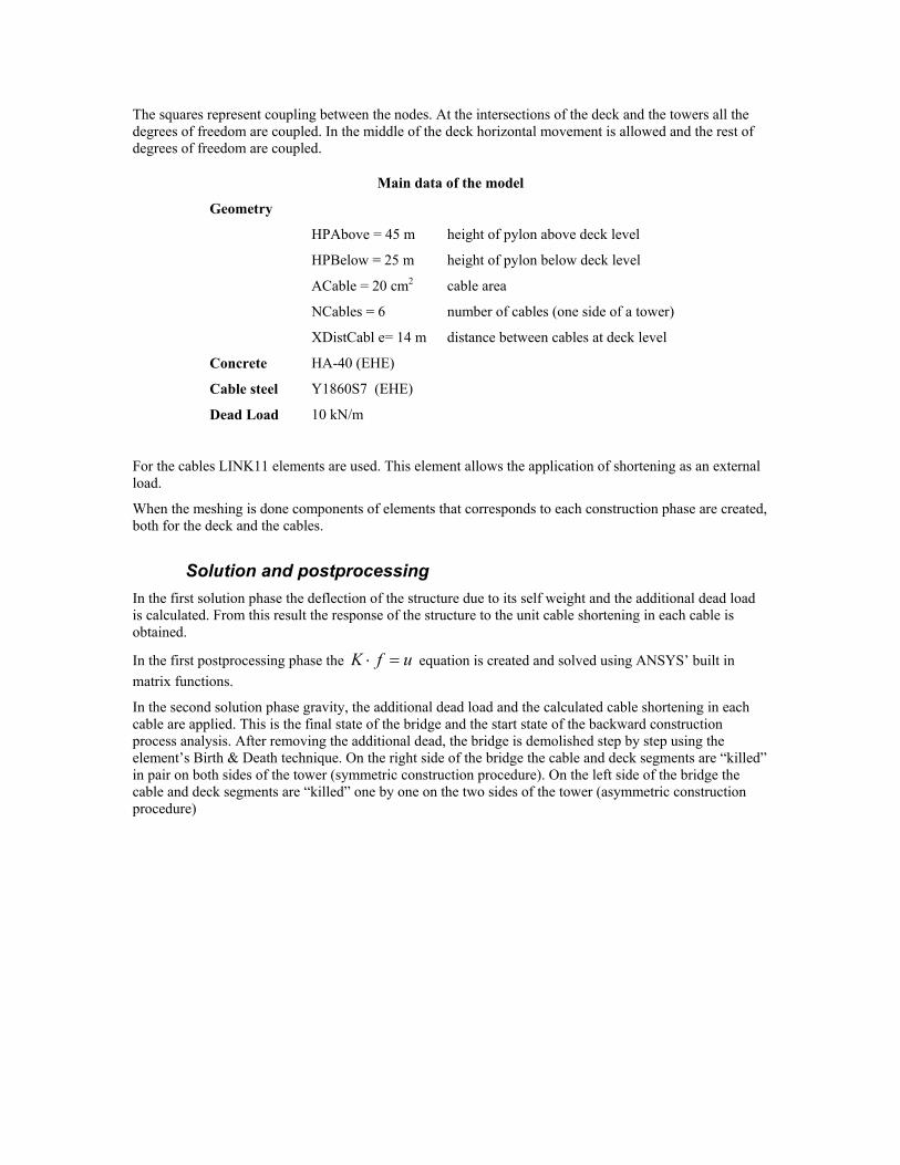
The squares represent coupling between the nodes. At the intersections of the deck and the towers all the degrees of freedom are coupled. In the middle of the deck horizontal movement is allowed and the rest of degrees of freedom are coupled.
Main data of the model
Geometry
HPAbove = 45 m height of pylon above deck level
HPBelow = 25 m height of pylon below deck level
ACable = 20 cm2 cable area
NCables = 6 number of cables (one side of a tower)
XDistCabl e= 14 m distance between cables at deck level
Concrete HA-40 (EHE)
Cable steel Y1860S7 (EHE)
Dead Load 10 kN/m
For the cables LINK11 elements are used. This element allows the application of shortening as an external load.
When the meshing is done components of elements that corresponds to each construction phase are created, both for the deck and the cables.
Solution and postprocessing In the first solution phase the deflection of the structure due to its self weight and the additional dead load is calculated. From this result the response of the structure to the unit cable shortening in each cable is obtained.
In the first postprocessing phase the ufK =⋅ equation is created and solved using ANSYS’ built in matrix functions.
In the second solution phase gravity, the additional dead load and the calculated cable shortening in each cable are applied. This is the final state of the bridge and the start state of the backward construction process analysis. After removing the additional dead, the bridge is demolished step by step using the element’s Birth & Death technique. On the right side of the bridge the cable and deck segments are “killed” in pair on both sides of the tower (symmetric construction procedure). On the left side of the bridge the cable and deck segments are “killed” one by one on the two sides of the tower (asymmetric construction procedure)
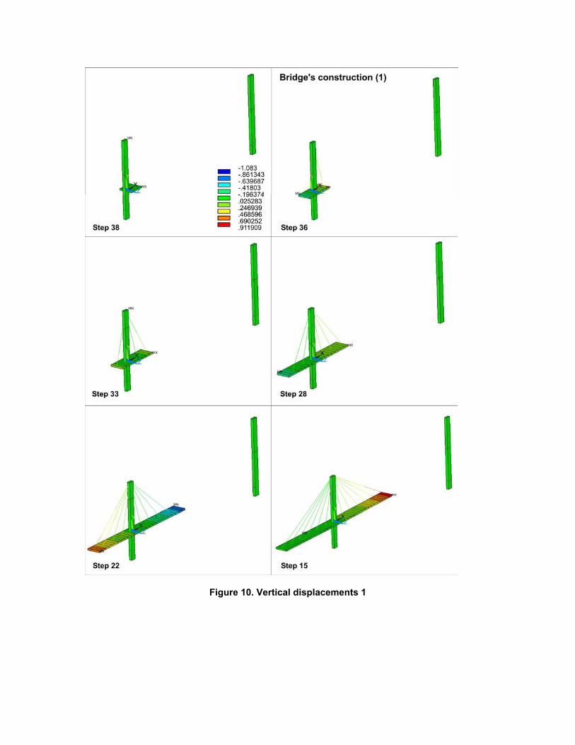
Figure 10. Vertical displacements 1
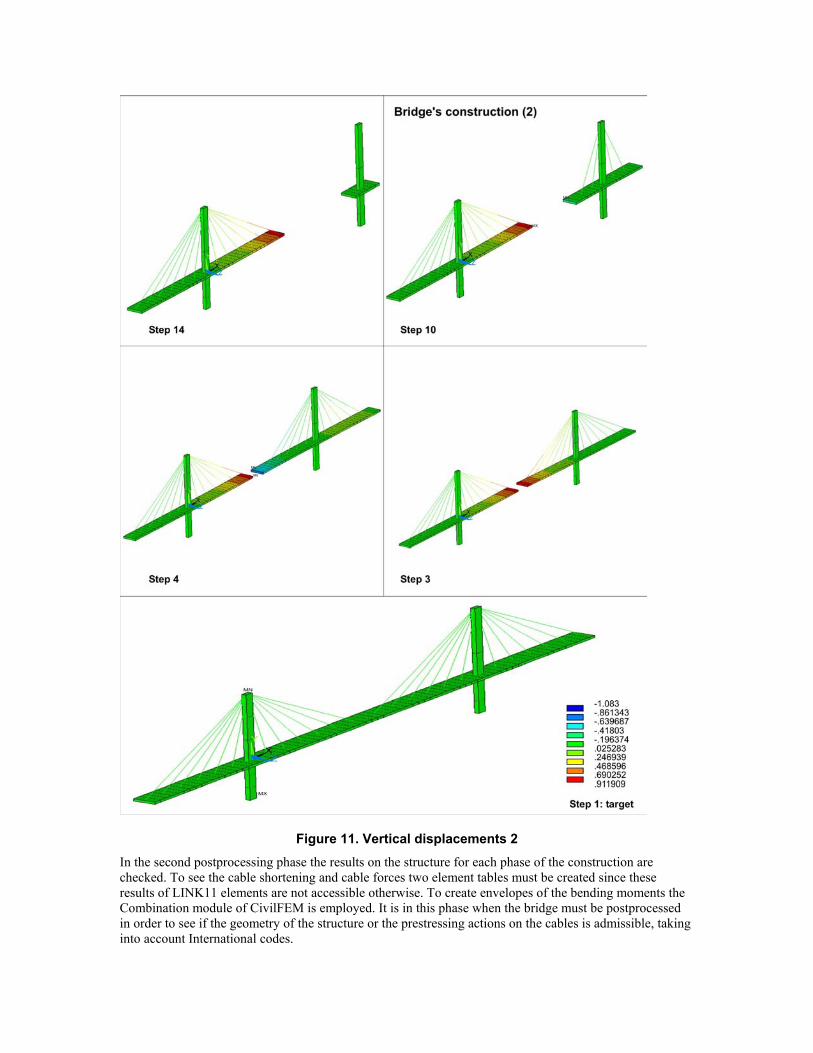
Figure 11. Vertical displacements 2 In the second postprocessing phase the results on the structure for each phase of the construction are checked. To see the cable shortening and cable forces two element tables must be created since these results of LINK11 elements are not accessible otherwise. To create envelopes of the bending moments the Combination module of CivilFEM is employed. It is in this phase when the bridge must be postprocessed in order to see if the geometry of the structure or the prestressing actions on the cables is admissible, taking into account International codes.

Once the results are checked to satisfy the building code, the history of the cable force variation is generated in the third postprocessing phase (figure 12). This result is very important for the building of the bridge because it is the procedure that will be followed for the prestressing of each cable as the construction process goes on.
Figure 12. Cable forces
Conclusion The algorithm described provides an accurate method to obtain the needed prestressing forces in the cables of a cable-stayed bridge, for each of the construction phases. This method allows to solve the bridge in a very short time, which provides obvious benefits compared with other optimization methods, without having to use approximations. This accurate and rapid performance, in conjunction with the preprocessing utilities available, allows the engineer to spend more time in shape design optimization and allows to compare different solutions to obtain the best suitable one.
The postprocessing of the bridge analysis provides a quick review of the structural behavior. It also gives valuable information for the construction of the bridge by automatically exporting the prestressing forces of each cable, at each construction step.


![[TECH]Cable Stayed Bridges](https://img.pdfslide.us/doc/110x75/544cd985b1af9f3a0b8b4c5b/techcable-stayed-bridges.jpg)
