Embed Size (px)
DESCRIPTION
advance steel
Citation preview
Advance Steel COM APIDeveloper Training Guide
ADVANCE STEEL COM API DEVELOPER TRAINING GUIDE
Contents
Chapter 1 Advance Steel Development possibilities.............................................................................5
1.1 Introduction to the Advance Steel API....................................................................................6
1.2 What can you do with the Advance Steel API?......................................................................6
1.3 Requirements......................................................................................................................... 6
1.4 Installation.............................................................................................................................. 6
Chapter 2 Advance Steel Modeling.......................................................................................................7
2.1 What are joints?..................................................................................................................... 8
2.2 Joint description..................................................................................................................... 8
2.3 How joints work?....................................................................................................................8
2.4 Commands description..........................................................................................................9
Chapter 3 Advance Steel Modeling API Presentation.........................................................................11
3.1 Geometry API....................................................................................................................... 12
3.1.1 IPoint3d........................................................................................................................ 12
3.1.2 IVector3d...................................................................................................................... 13
3.1.3 ILine3d......................................................................................................................... 14
3.1.4 IPlane........................................................................................................................... 15
3.1.5 ICS3d........................................................................................................................... 16
3.1.6 IAugPolygon3d.............................................................................................................17
3.2 Modeling API........................................................................................................................ 18
3.2.1 Beams.......................................................................................................................... 19
3.2.2 Plates........................................................................................................................... 26
3.2.3 Features....................................................................................................................... 32
3.2.4 Special parts................................................................................................................. 37
3.2.5 Gratings........................................................................................................................ 38
3.2.6 Bolts, Welds and Anchors............................................................................................39
Chapter 4 Joints API........................................................................................................................... 43
4.1 User interface....................................................................................................................... 44
4.2 Query method...................................................................................................................... 44
4.3 CreateObjects method.........................................................................................................44
4.4 InField/OutField methods.....................................................................................................44
4.5 GetUserPages method.........................................................................................................44
4.6 GetTableName method........................................................................................................45
4.7 GetExportData..................................................................................................................... 45
4.8 GetFeatureName.................................................................................................................45
4.9 FreeUserPages.................................................................................................................... 45
4.10 Libraries............................................................................................................................... 45
4.11 Attributes and categories......................................................................................................46
4.12 JointTransfer........................................................................................................................ 46
3
ADVANCE STEEL COM API DEVELOPER TRAINING GUIDE
4.13 Database Structure..............................................................................................................46
4.14 Joint table............................................................................................................................. 47
4.15 Developing a joint................................................................................................................. 47
4.15.1 Visual Studio solution...................................................................................................47
4.15.2 Create GUID................................................................................................................. 51
4.15.3 Build the program.........................................................................................................51
4.15.4 Add records in database..............................................................................................51
4.15.5 User interface...............................................................................................................52
4.15.6 Create first page...........................................................................................................53
4.15.7 Add ActiveX control......................................................................................................53
4.15.8 Control Properties........................................................................................................54
4.15.9 Run joint....................................................................................................................... 55
Chapter 5 Joints Design API...............................................................................................................57
5.1.1 Implementation of a joint calculation module................................................................58
5.1.2 How it works?...............................................................................................................58
5.1.3 Communication interface..............................................................................................58
5.1.4 Description of interface methods..................................................................................59
5.1.5 Database Structure......................................................................................................61
5.2 Developing a joint design.....................................................................................................61
Chapter 6 Advance Steel Scripting Possibilities.................................................................................65
6.1 Advance Steel Lisp API........................................................................................................66
6.2 Numbering scripts................................................................................................................66
6.2.1 Workflow...................................................................................................................... 66
6.2.2 Numbering standard parts............................................................................................66
6.2.3 Numbering prefix..........................................................................................................67
6.2.4 Main part of an assembly.............................................................................................67
6.2.5 Numbering methods.....................................................................................................67
6.3 Drawing styles scripts..........................................................................................................69
6.3.1 Overview...................................................................................................................... 69
6.4 Drawing process scripts.......................................................................................................70
6.4.1 Overview...................................................................................................................... 70
6.5 BOM pre-processing using XSLT.........................................................................................72
4

1 Chapter 1Advance Steel Development possibilities

1.1 Introduction to the Advance Steel API
The Advance Steel API allows you to program with any .NET compliant language including Visual Basic.NET, C#, and C++. Before using the API, learn to use Advance Steel and its features so that you can better understand this API.
1.2 What can you do with the Advance Steel API?
Create joints Create commands
1.3 Requirements
Understanding Advance Steel Programming language like C# or VB.NET Microsoft Visual Studio 2013 or Microsoft Visual Studio 2013 Express Edition Advance Steel 2016
1.4 Installation
The Advance Steel API is installed with Advance Steel. Microsoft Visual Studio 2013 Express can be downloaded from http://www.visualstudio.com/en-us/products/visual-studio-express-vs.aspx
2 Chapter 2Advance Steel Modeling

2.1 What are joints?
Joints are complex elements that consist of basic elements and dependent elements that are controlled by a construction rule.
All individual elements in the joint, including their properties and processing objects, are held together and represented as a gray box (connection object).
All connection objects and definitions are included in the gray box.
2.2 Joint descriptionA joint is created through an object which implements the IRule interface and uses the IJoint interface to create Advance Steel elements.
Joint workflow:
Input definition (Query)
Create objects (CreateObjects)
Display dialog (GetUserPages)
Through a joint, the created objects depend on the selected input objects, as long as the joint object exists in the dwg. The created objects or their properties are modifiable at any time using the joint properties dialog box. Previously created objects can be updated.
The IRule interface Query method is called when a joint should be created. In this method you can select the input objects for your joint and to initialize default parameters.
The IRule interface CreateObjects contains the joint functionality. It uses the global variables declared in the declaration section and do the main work. The IRule interface GetUserPages is called when the “Advance Steel Joint Properties" command is invoked.
The IJointInfo interface properties are interrogated to get information about the developer. You need to add a record in AstorRules.HRLDefinition and AstorRules.RulesDllSigned tables after developing a joint to be able to execute it in Advance Steel.
The joint can be executed with a command like"AstM4CrConByVB RuleName" or "AstM4CommStructAsJointVB box RuleName"
2.3 How joints work?
Advance Steel creates and modifies joints by using rules. The IRule interface defines several methods/properties, each being responsible for a certain task.
The Joint provides the link of IRule with the underlying Joint object of Advance Steel. The Joint object is set by Advance Steel before calling any method of the Rule.
The Query method describes the input parameters of the joint. Its implementation should ask for the user for input with the help of IAstUI and add the necessary entities to InputObjects of the joint.
Note: If the joint is called with "AstM4CommStructAsJointVB box RuleName" the InputObjects array contains an element (the structural box) of type IStructuralBox in the beginning of the Query Method. You can take the box parameter from the InputObjects array and use it or modify it.
ADVANCE STEEL COM API DEVELOPER TRAINING GUIDE
The CreateObjects method should create Advance Steel objects and add them to the CreatedObjects of the joint. Rules can be written by anybody. The Advance Steel framework is able to execute them at runtime. Thus, several services are provided - creation, list, modification, explode, deletion of a joint object:
A joint object is created along with its driven objects. A dialog box appears displaying all the parameters which apply to that joint category.
AutoCAD’s list command lists the joint type (and parameters in later versions).
Editing a joint object leads to the appropriate dialog box.
Exploding an object means deleting the “logical joint unit” while maintaining the driven objects. These objects will live explicitly then and will not know anything about the joint anymore.
Deleting an object means deleting the logical unit and the driven objects as well. This includes features at driving objects, e.g. beam notches etc.
2.4 Commands description
A command is created through an object which implements the IExternalMethod interface defined by AstSTEELAUTOMATIONLib library. The difference between joint is that, the command is a “once-only” logic type, being unable to update already created objects. The Run method must be implemented.The command can be executed “AstM9CommExecuteExternalCode commandName”
9
3 Chapter 3Advance Steel Modeling API Presentation
3.1 Geometry API
These are the basic geometric objects. In any joint that will be developed you will have to use at least a few of these objects (IPoint3d, IVector3d, IPlane, etc.).
3.1.1 IPoint3d
3.1.1.1 Properties
X (property) - Gets or sets the x coordinate of the point. Y (property) - Gets or sets the y coordinate of the point. Z (property) - Gets or sets the z coordinate of the point.
3.1.1.2 Methods
Add(IVector3d VectorToAdd) - Adds the specified vector to this point. Create(double dfX, double dfY, double dfZ) - Creates the point with specified coordinates. DistanceTo(IPoint3d target) - Returns the distance between points.Project(IPlane targetPlane, IVector3d projDir) - Projects the point on the specified plane, along
the direction given by the vector.Subtract(IPoint3d Subtracter) - Returns a vector, oriented from subtracter to this point:
p1.Subtract(p2) – the vector is oriented from p2 to p1TransformBy(IMatrix3d TransformMatrix) - Applies the transformation specified by the matrix to
this point.
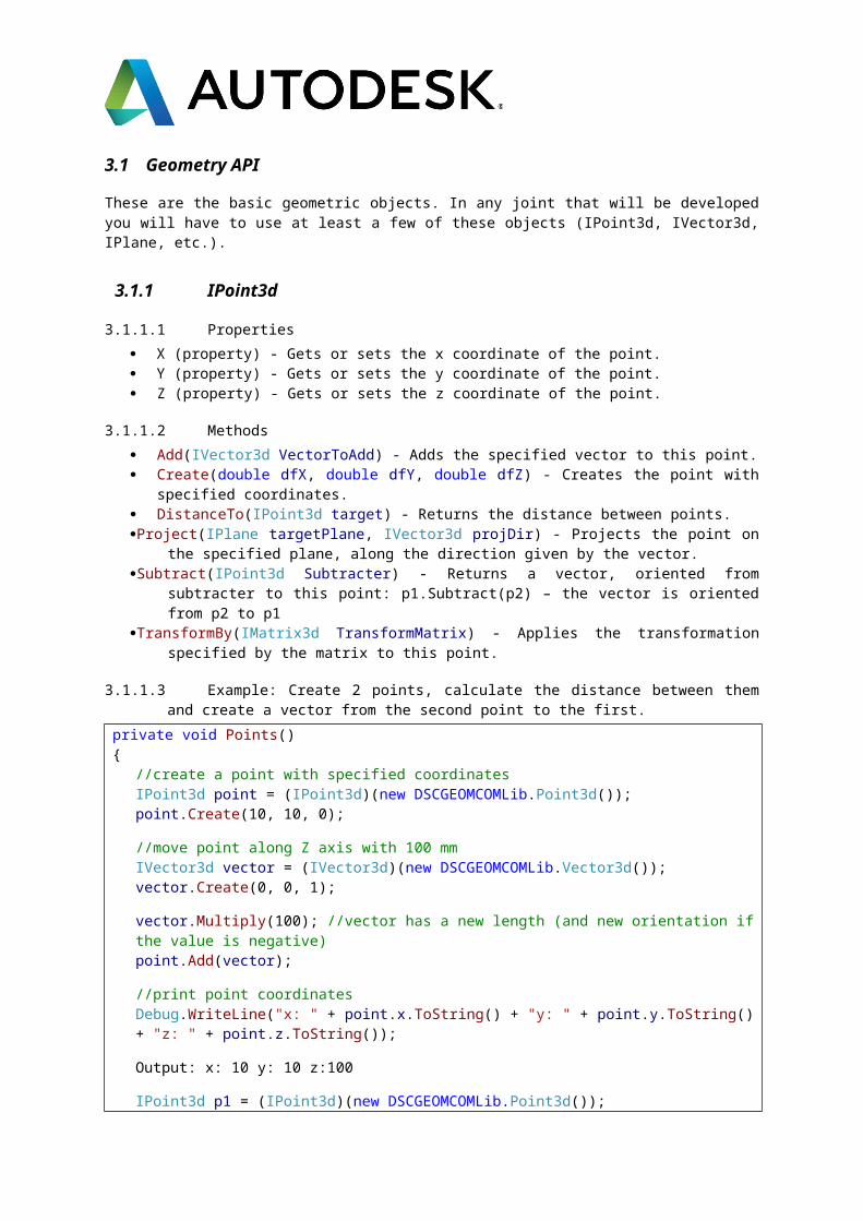
3.1.1.3 Example: Create 2 points, calculate the distance between them and create a vector from the second point to the first.
private void Points(){
//create a point with specified coordinatesIPoint3d point = (IPoint3d)(new DSCGEOMCOMLib.Point3d());point.Create(10, 10, 0);
//move point along Z axis with 100 mmIVector3d vector = (IVector3d)(new DSCGEOMCOMLib.Vector3d());vector.Create(0, 0, 1);
vector.Multiply(100); //vector has a new length (and new orientation if the value is negative)point.Add(vector);
//print point coordinatesDebug.WriteLine("x: " + point.x.ToString() + "y: " + point.y.ToString() + "z: " + point.z.ToString());
Output: x: 10 y: 10 z:100
IPoint3d p1 = (IPoint3d)(new DSCGEOMCOMLib.Point3d());IPoint3d p2 = (IPoint3d)(new DSCGEOMCOMLib.Point3d());
p1.Create(0, 0, 0);p2.Create(50, 0, 0);
double distance = p1.DistanceTo(p2);//print distance between pointsDebug.WriteLine("Distance between points is: " + distance.ToString());
Output: Distance between points is: 50.0
//return a vector oriented from p2 to p1vector = p1.Subtract(p2);
ADVANCE STEEL COM API DEVELOPER TRAINING GUIDE
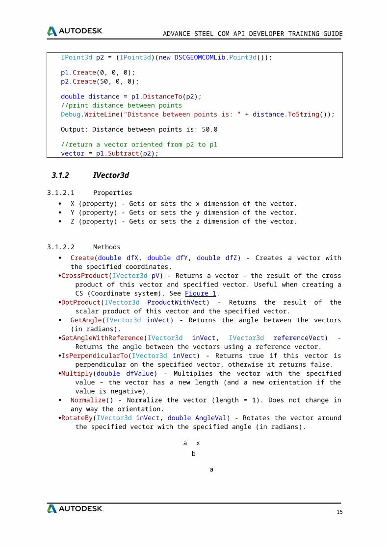
3.1.2 IVector3d
3.1.2.1 Properties
X (property) - Gets or sets the x dimension of the vector. Y (property) - Gets or sets the y dimension of the vector. Z (property) - Gets or sets the z dimension of the vector.
3.1.2.2 Methods
Create(double dfX, double dfY, double dfZ) - Creates a vector with the specified coordinates.CrossProduct(IVector3d pV) - Returns a vector - the result of the cross product of this vector and
specified vector. Useful when creating a CS (Coordinate system). See Figure 1.DotProduct(IVector3d ProductWithVect) - Returns the result of the scalar product of this vector
and the specified vector. GetAngle(IVector3d inVect) - Returns the angle between the vectors (in radians).GetAngleWithReference(IVector3d inVect, IVector3d referenceVect) - Returns the angle
between the vectors using a reference vector.IsPerpendicularTo(IVector3d inVect) - Returns true if this vector is perpendicular on the specified
vector, otherwise it returns false.Multiply(double dfValue) - Multiplies the vector with the specified value – the vector has a new
length (and a new orientation if the value is negative). Normalize() - Normalize the vector (length = 1). Does not change in any way the orientation.RotateBy(IVector3d inVect, double AngleVal) - Rotates the vector around the specified vector
with the specified angle (in radians).
Figure 1.
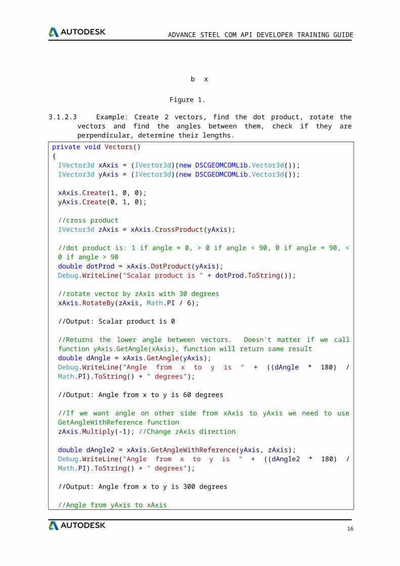
3.1.2.3 Example: Create 2 vectors, find the dot product, rotate the vectors and find the angles between them, check if they are perpendicular, determine their lengths.
private void Vectors(){
IVector3d xAxis = (IVector3d)(new DSCGEOMCOMLib.Vector3d());IVector3d yAxis = (IVector3d)(new DSCGEOMCOMLib.Vector3d());
xAxis.Create(1, 0, 0);yAxis.Create(0, 1, 0);
//cross productIVector3d zAxis = xAxis.CrossProduct(yAxis);
//dot product is: 1 if angle = 0, > 0 if angle < 90, 0 if angle = 90, < 0 if angle > 90double dotProd = xAxis.DotProduct(yAxis);Debug.WriteLine("Scalar product is " + dotProd.ToString());
//rotate vector by zAxis with 30 degreesxAxis.RotateBy(zAxis, Math.PI / 6);
//Output: Scalar product is 0
13
a x b
a
b
b x a
ADVANCE STEEL COM API DEVELOPER TRAINING GUIDE
//Returns the lower angle between vectors. Doesn't matter if we call function yAxis.GetAngle(xAxis), function will return same resultdouble dAngle = xAxis.GetAngle(yAxis);Debug.WriteLine("Angle from x to y is " + ((dAngle * 180) / Math.PI).ToString() + " degrees");
//Output: Angle from x to y is 60 degrees
//If we want angle on other side from xAxis to yAxis we need to use GetAngleWithReference functionzAxis.Multiply(-1); //Change zAxis direction
double dAngle2 = xAxis.GetAngleWithReference(yAxis, zAxis);Debug.WriteLine("Angle from x to y is " + ((dAngle2 * 180) / Math.PI).ToString() + " degrees");
//Output: Angle from x to y is 300 degrees
//Angle from yAxis to xAxisdAngle2 = yAxis.GetAngleWithReference(xAxis, zAxis);Debug.WriteLine("Angle from y to x is " + ((dAngle2 * 180) / Math.PI).ToString() + " degrees");
//Output: Angle from y to x is 60 degrees
if(zAxis.IsPerpendicularTo(xAxis)){ Debug.WriteLine("Vectors are perpendicular!");}
//Output: Vectors are perpendicular!
zAxis.Multiply(57);Debug.WriteLine("Vector length is " + zAxis.Length.ToString());
//Output: Vector length is 57
zAxis.Normalize(); //Normalize vectorDebug.WriteLine("Vector length is " + zAxis.Length.ToString());
//Output: Vector length is 1}
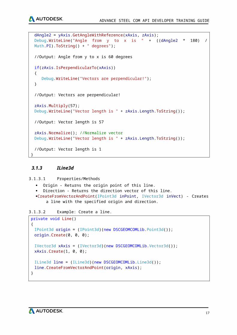
3.1.3 ILine3d
3.1.3.1 Properties/Methods
Origin - Returns the origin point of this line. Direction - Returns the direction vector of this line.CreateFromVectorAndPoint(IPoint3d inPoint, IVector3d inVect) - Creates a line with the specified
origin and direction.
3.1.3.2 Example: Create a line.
private void Line(){
IPoint3d origin = (IPoint3d)(new DSCGEOMCOMLib.Point3d());origin.Create(0, 0, 0);
IVector3d xAxis = (IVector3d)(new DSCGEOMCOMLib.Vector3d());xAxis.Create(1, 0, 0);
14
ADVANCE STEEL COM API DEVELOPER TRAINING GUIDE
ILine3d line = (ILine3d)(new DSCGEOMCOMLib.Line3d());line.CreateFromVectorAndPoint(origin, xAxis);
}
3.1.4 IPlane
3.1.4.1 Properties/Methods
PointOnPlane - Returns the origin of this plane. Normal - Returns the plane’s normal vector.CreateFromPointAndNormal(IPoint3d inPoint, IVector3d inVect) - Create a plane with the
specified origin and normal. get_DistanceTo(IPoint3d ptIn) - Returns the distance from this plane to the input pointintersectWithLine(ILine3d inLine, out IPoint3d ptIntersection) - Calculates the intersection point of
this plane with a line. Returns True or False depending on whether the objects intersect.
3.1.4.2 Example: Create a plane and a line and find the intersection point where the line meets the plane.
private void Planes(){ IPoint3d origin = (IPoint3d)(new DSCGEOMCOMLib.Point3d()); origin.Create(100, 100, 100);
IVector3d normal = (IVector3d)(new DSCGEOMCOMLib.Vector3d()); normal.Create(0, 0, 1);
//create plane from point and normal IPlane plane = (IPlane)(new DSCGEOMCOMLib.plane()); plane.CreateFromPointAndNormal(origin, normal);
IPoint3d pt = (IPoint3d)(new DSCGEOMCOMLib.Point3d()); pt.Create(20, 30, -45);
//get perpendicular distance from point to plane double distance = plane.get_DistanceTo(pt); Debug.WriteLine("Distance from point to plane is " + distance);
//Output: Distance from point to plane is 145
ILine3d line = (ILine3d)(new DSCGEOMCOMLib.Line3d()); line.CreateFromVectorAndPoint(pt, normal);
//intersect line with plane IPoint3d ptInt;
if(plane.intersectWithLine(line, out ptInt)) { Debug.WriteLine("Intersection point is " + ptInt.x + ", " + ptInt.y + ", " + ptInt.z); } //Output: Intersection point is (20, 30, 100)}
3.1.5 ICS3d
15
ADVANCE STEEL COM API DEVELOPER TRAINING GUIDE
There are two coordinate Systems: - fixed system called World Coordinate System (WCS), and a movable system called User Coordinate System (UCS). When create a beam for example you need to specify a coordinate system where beam will be created. Coordinate systems can make easier your work when create joints. A coordinate system is defined by three axes (vectors) and origin point. The axes define three coordinate planes. The (XY) plane contains the x - axis and the y- axis. The (YZ) contains the y - axis and z - axis. The (XZ) plane contains x - axis and z- axis. Origin point is at intersection of these planes.
3.1.5.1 Properties
Origin - Gets or sets the CS origin (as a Point3d). XAxis - Gets or sets the CS X axis (as a Vector3d). YAxis - Gets or sets the CS Y axis (as a Vector3d). ZAxis - Gets or sets the CS Z axis (as a Vector3d).
3.1.5.2 Methods
RotateCSAroundX(double AngleVal) - Rotates the CS around X axis with the specified angle value (in radians).
RotateCSAroundY(double AngleVal) - Rotates the CS around Y axis with the specified angle value (in radians).
RotateCSAroundZ(double AngleVal) - Rotates the CS around Z axis with the specified angle value (in radians).
TransformBy(IMatrix3d TransforMatrix) - Applies the transformation specified by the matrix to this CS.
TranslateCS(IVector3d TranslationVect) - Translates the CS origin with the specified vector. The vector is interpreted as being in this CS, not in WCS. For example: To translate this CS along its own X-axis the vector (1, 0, 0) multiplied by the desired value should be passed to this method.
SetToAlignCS(ICS3d pToCS) - Returns the Matrix3d that transforms objects from this coordinate system to the “pToCS” coordinate system (the matrix can be used in an object.TransformBy(matrix) method call).
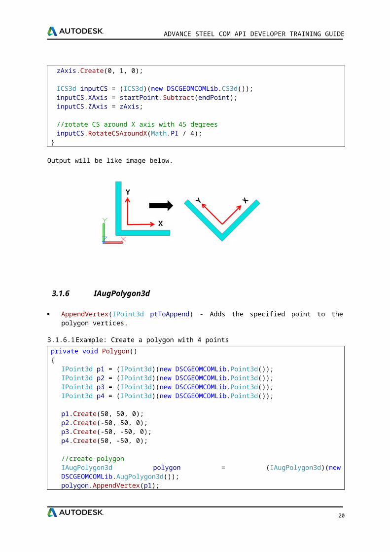
3.1.5.3 Example: Create a coordinate system and rotate it by 45 degrees
private void CreateCS(){
IVector3d zAxis = (IVector3d)(new DSCGEOMCOMLib.Vector3d());zAxis.Create(0, 1, 0);
ICS3d inputCS = (ICS3d)(new DSCGEOMCOMLib.CS3d());inputCS.XAxis = startPoint.Subtract(endPoint);inputCS.ZAxis = zAxis;
//rotate CS around X axis with 45 degreesinputCS.RotateCSAroundX(Math.PI / 4);
}
Output will be like image below.
16
ADVANCE STEEL COM API DEVELOPER TRAINING GUIDE
3.1.6 IAugPolygon3d
AppendVertex(IPoint3d ptToAppend) - Adds the specified point to the polygon vertices.
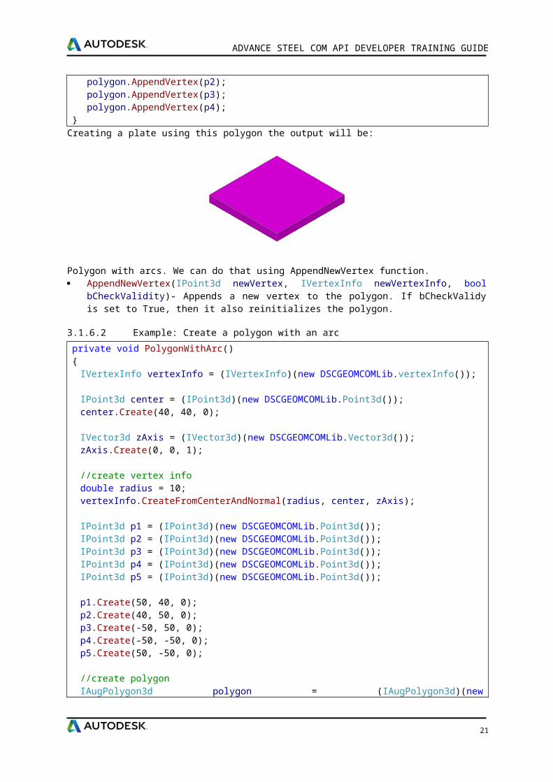
3.1.6.1 Example: Create a polygon with 4 points
private void Polygon(){
IPoint3d p1 = (IPoint3d)(new DSCGEOMCOMLib.Point3d());IPoint3d p2 = (IPoint3d)(new DSCGEOMCOMLib.Point3d());IPoint3d p3 = (IPoint3d)(new DSCGEOMCOMLib.Point3d());IPoint3d p4 = (IPoint3d)(new DSCGEOMCOMLib.Point3d());
p1.Create(50, 50, 0);p2.Create(-50, 50, 0);p3.Create(-50, -50, 0);p4.Create(50, -50, 0);
//create polygonIAugPolygon3d polygon = (IAugPolygon3d)(new DSCGEOMCOMLib.AugPolygon3d());polygon.AppendVertex(p1);polygon.AppendVertex(p2);polygon.AppendVertex(p3);polygon.AppendVertex(p4);
}Creating a plate using this polygon the output will be:
Polygon with arcs. We can do that using AppendNewVertex function. AppendNewVertex(IPoint3d newVertex, IVertexInfo newVertexInfo, bool bCheckValidity)-
Appends a new vertex to the polygon. If bCheckValidy is set to True, then it also reinitializes the polygon.
3.1.6.2 Example: Create a polygon with an arc
private void PolygonWithArc()
17
ADVANCE STEEL COM API DEVELOPER TRAINING GUIDE
{IVertexInfo vertexInfo = (IVertexInfo)(new DSCGEOMCOMLib.vertexInfo());
IPoint3d center = (IPoint3d)(new DSCGEOMCOMLib.Point3d());center.Create(40, 40, 0);
IVector3d zAxis = (IVector3d)(new DSCGEOMCOMLib.Vector3d());zAxis.Create(0, 0, 1);
//create vertex infodouble radius = 10;vertexInfo.CreateFromCenterAndNormal(radius, center, zAxis);
IPoint3d p1 = (IPoint3d)(new DSCGEOMCOMLib.Point3d());IPoint3d p2 = (IPoint3d)(new DSCGEOMCOMLib.Point3d());IPoint3d p3 = (IPoint3d)(new DSCGEOMCOMLib.Point3d());IPoint3d p4 = (IPoint3d)(new DSCGEOMCOMLib.Point3d());IPoint3d p5 = (IPoint3d)(new DSCGEOMCOMLib.Point3d());
p1.Create(50, 40, 0);p2.Create(40, 50, 0);p3.Create(-50, 50, 0);p4.Create(-50, -50, 0);p5.Create(50, -50, 0);
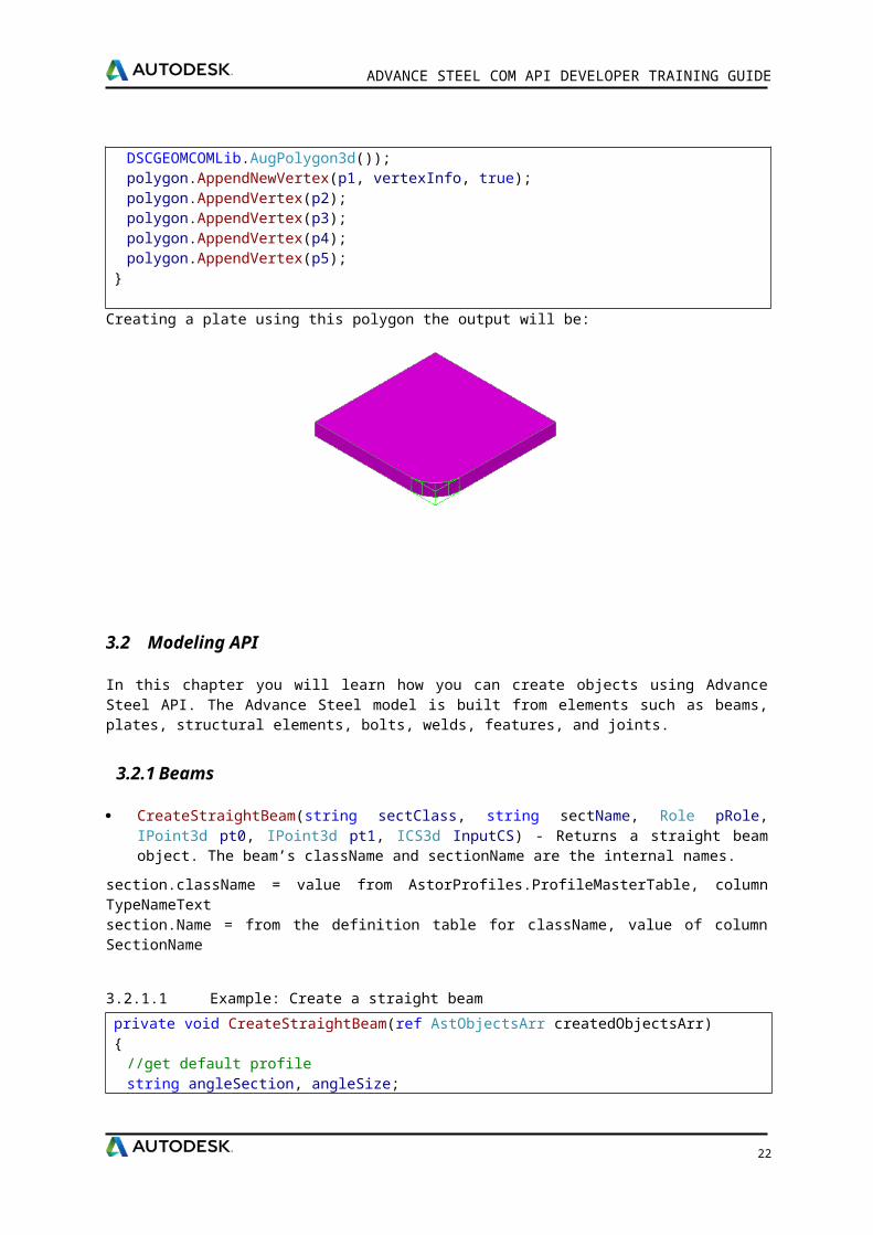
//create polygonIAugPolygon3d polygon = (IAugPolygon3d)(new DSCGEOMCOMLib.AugPolygon3d());polygon.AppendNewVertex(p1, vertexInfo, true);polygon.AppendVertex(p2);polygon.AppendVertex(p3);polygon.AppendVertex(p4);polygon.AppendVertex(p5);
}
Creating a plate using this polygon the output will be:
3.2 Modeling API
In this chapter you will learn how you can create objects using Advance Steel API. The Advance Steel model is built from elements such as beams, plates, structural elements, bolts, welds, features, and joints.
18
ADVANCE STEEL COM API DEVELOPER TRAINING GUIDE
3.2.1 Beams
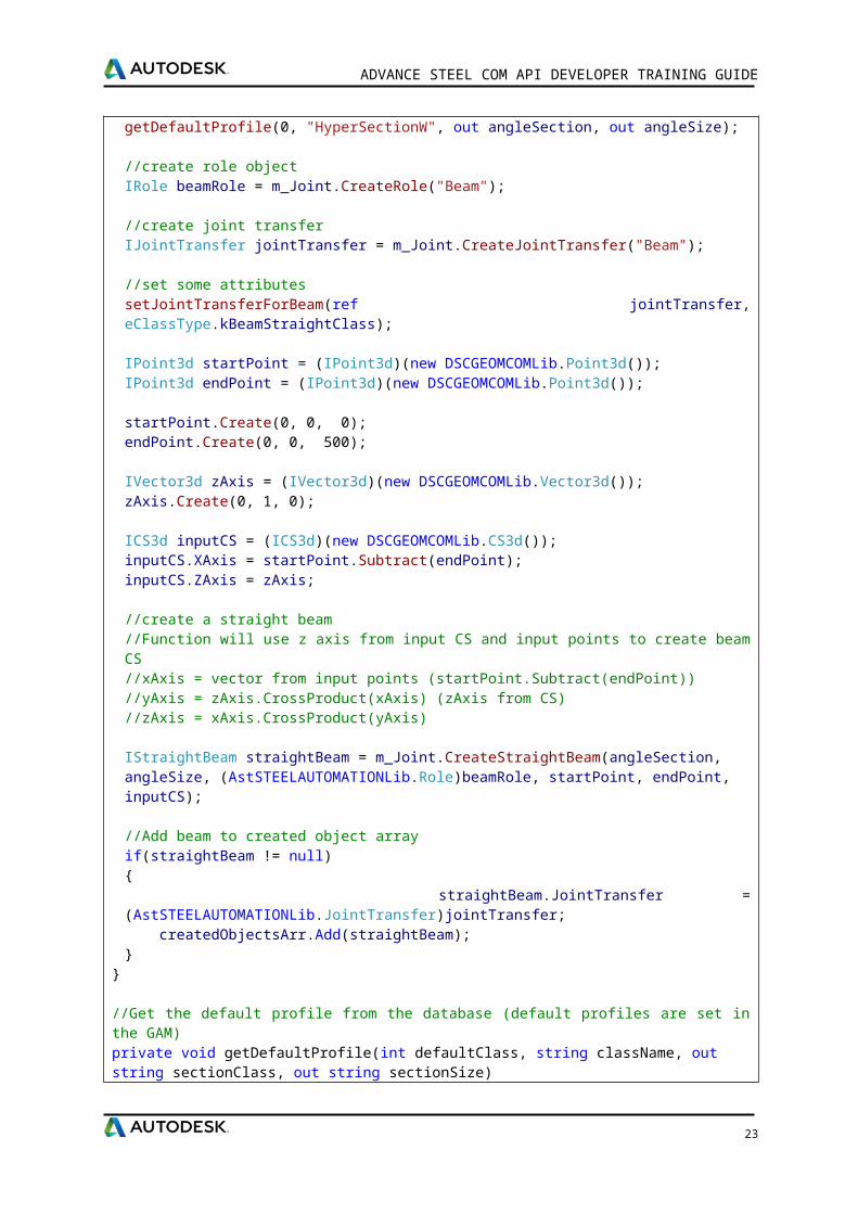
CreateStraightBeam(string sectClass, string sectName, Role pRole, IPoint3d pt0, IPoint3d pt1, ICS3d InputCS) - Returns a straight beam object. The beam’s className and sectionName are the internal names.
section.className = value from AstorProfiles.ProfileMasterTable, column TypeNameTextsection.Name = from the definition table for className, value of column SectionName
3.2.1.1 Example: Create a straight beam
private void CreateStraightBeam(ref AstObjectsArr createdObjectsArr){
//get default profilestring angleSection, angleSize;getDefaultProfile(0, "HyperSectionW", out angleSection, out angleSize);
//create role objectIRole beamRole = m_Joint.CreateRole("Beam");
//create joint transferIJointTransfer jointTransfer = m_Joint.CreateJointTransfer("Beam");
//set some attributessetJointTransferForBeam(ref jointTransfer, eClassType.kBeamStraightClass);
IPoint3d startPoint = (IPoint3d)(new DSCGEOMCOMLib.Point3d());IPoint3d endPoint = (IPoint3d)(new DSCGEOMCOMLib.Point3d());
startPoint.Create(0, 0, 0);endPoint.Create(0, 0, 500);
IVector3d zAxis = (IVector3d)(new DSCGEOMCOMLib.Vector3d());zAxis.Create(0, 1, 0);
ICS3d inputCS = (ICS3d)(new DSCGEOMCOMLib.CS3d());inputCS.XAxis = startPoint.Subtract(endPoint);inputCS.ZAxis = zAxis;
//create a straight beam//Function will use z axis from input CS and input points to create beam CS//xAxis = vector from input points (startPoint.Subtract(endPoint))//yAxis = zAxis.CrossProduct(xAxis) (zAxis from CS)//zAxis = xAxis.CrossProduct(yAxis)
IStraightBeam straightBeam = m_Joint.CreateStraightBeam(angleSection, angleSize, (AstSTEELAUTOMATIONLib.Role)beamRole, startPoint, endPoint, inputCS); //Add beam to created object arrayif(straightBeam != null){ straightBeam.JointTransfer = (AstSTEELAUTOMATIONLib.JointTransfer)jointTransfer; createdObjectsArr.Add(straightBeam);}
}
//Get the default profile from the database (default profiles are set in the GAM)private void getDefaultProfile(int defaultClass, string className, out string sectionClass, out string sectionSize)
19
ADVANCE STEEL COM API DEVELOPER TRAINING GUIDE
{sectionClass = "";sectionSize = "";
IOdbcUtils tableUtils = (IOdbcUtils)(new DSCODBCCOMLib.OdbcUtils());string sSectionProf = tableUtils.GetDefaultString(defaultClass, className);
string separator = "#@" + '§' + "@#";string[] section = sSectionProf.Split(new string[] { separator }, StringSplitOptions.None);
if (section.Length == 2){
sectionClass = section[0]; sectionSize = section[1];}
}//Create the JointTransfer for a beamprivate void setJointTransferForBeam(ref IJointTransfer jointTrans, eClassType classType){
jointTrans.ClassType = classType;
/set here all the properties which can be modified outside the jointjointTrans.set_Attribute(eAttributeCodes.kBeamDenotation, 1);jointTrans.set_Attribute(eAttributeCodes.kBeamMaterial, 1);jointTrans.set_Attribute(eAttributeCodes.kBeamCoating, 1);jointTrans.set_Attribute(eAttributeCodes.kBeamSinglePartNumber, 1);jointTrans.set_Attribute(eAttributeCodes.kBeamMainPartNumber, 1);jointTrans.set_Attribute(eAttributeCodes.kBeamSinglePartPrefix, 1);jointTrans.set_Attribute(eAttributeCodes.kBeamMainPartPrefix, 1);jointTrans.set_Attribute(eAttributeCodes.kBeamAssembly, 1);jointTrans.set_Attribute(eAttributeCodes.kBeamItemNumber, 1);jointTrans.set_Attribute(eAttributeCodes.kBeamSinglePartDetailStyle, 1);jointTrans.set_Attribute(eAttributeCodes.kBeamMainPartDetailStyle, 1);jointTrans.set_Attribute(eAttributeCodes.kBeamNote, 1);jointTrans.set_Attribute(eAttributeCodes.kBeamSPUsedForCollisionCheck, 1);jointTrans.set_Attribute(eAttributeCodes.kBeamSPUsedForNumbering, 1);jointTrans.set_Attribute(eAttributeCodes.kBeamSPDisplayRestriction, 1);jointTrans.set_Attribute(eAttributeCodes.kBeamSPExplicitQuantity, 1);jointTrans.set_Attribute(eAttributeCodes.kBeamMPUsedForCollisionCheck, 1);jointTrans.set_Attribute(eAttributeCodes.kBeamMPUsedForNumbering, 1);
}
20
ADVANCE STEEL COM API DEVELOPER TRAINING GUIDE
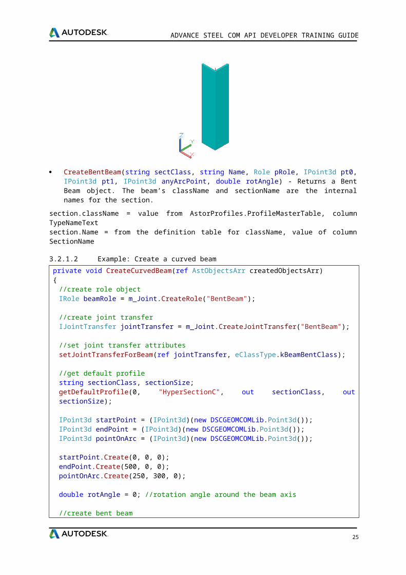
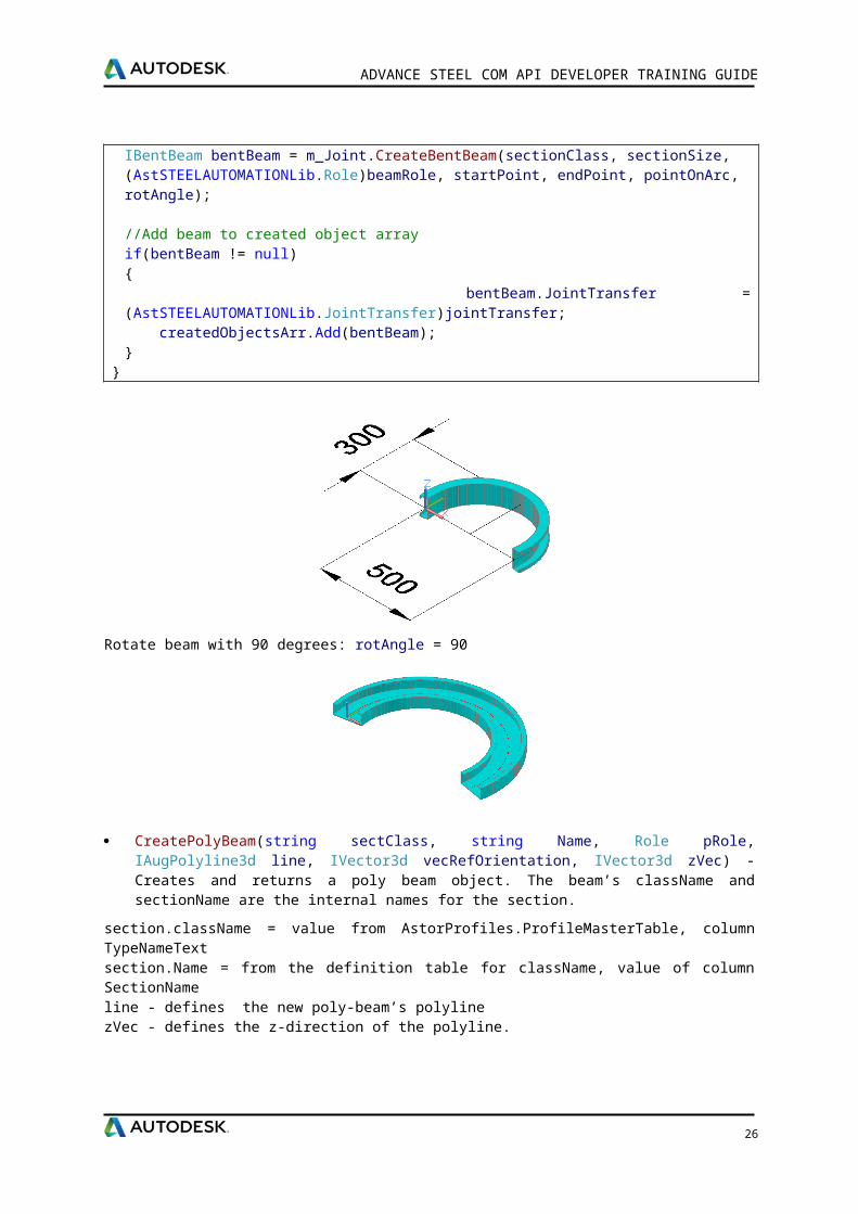
CreateBentBeam(string sectClass, string Name, Role pRole, IPoint3d pt0, IPoint3d pt1, IPoint3d anyArcPoint, double rotAngle) - Returns a Bent Beam object. The beam’s className and sectionName are the internal names for the section.
section.className = value from AstorProfiles.ProfileMasterTable, column TypeNameTextsection.Name = from the definition table for className, value of column SectionName
3.2.1.2 Example: Create a curved beam
private void CreateCurvedBeam(ref AstObjectsArr createdObjectsArr){
//create role objectIRole beamRole = m_Joint.CreateRole("BentBeam");
//create joint transferIJointTransfer jointTransfer = m_Joint.CreateJointTransfer("BentBeam");
//set joint transfer attributessetJointTransferForBeam(ref jointTransfer, eClassType.kBeamBentClass);
//get default profilestring sectionClass, sectionSize;getDefaultProfile(0, "HyperSectionC", out sectionClass, out sectionSize);
IPoint3d startPoint = (IPoint3d)(new DSCGEOMCOMLib.Point3d());IPoint3d endPoint = (IPoint3d)(new DSCGEOMCOMLib.Point3d());IPoint3d pointOnArc = (IPoint3d)(new DSCGEOMCOMLib.Point3d());
startPoint.Create(0, 0, 0);endPoint.Create(500, 0, 0);pointOnArc.Create(250, 300, 0);
double rotAngle = 0; //rotation angle around the beam axis
//create bent beamIBentBeam bentBeam = m_Joint.CreateBentBeam(sectionClass, sectionSize, (AstSTEELAUTOMATIONLib.Role)beamRole, startPoint, endPoint, pointOnArc, rotAngle);
//Add beam to created object arrayif(bentBeam != null){ bentBeam.JointTransfer = (AstSTEELAUTOMATIONLib.JointTransfer)jointTransfer; createdObjectsArr.Add(bentBeam);}
}
21
ADVANCE STEEL COM API DEVELOPER TRAINING GUIDE
Rotate beam with 90 degrees: rotAngle = 90
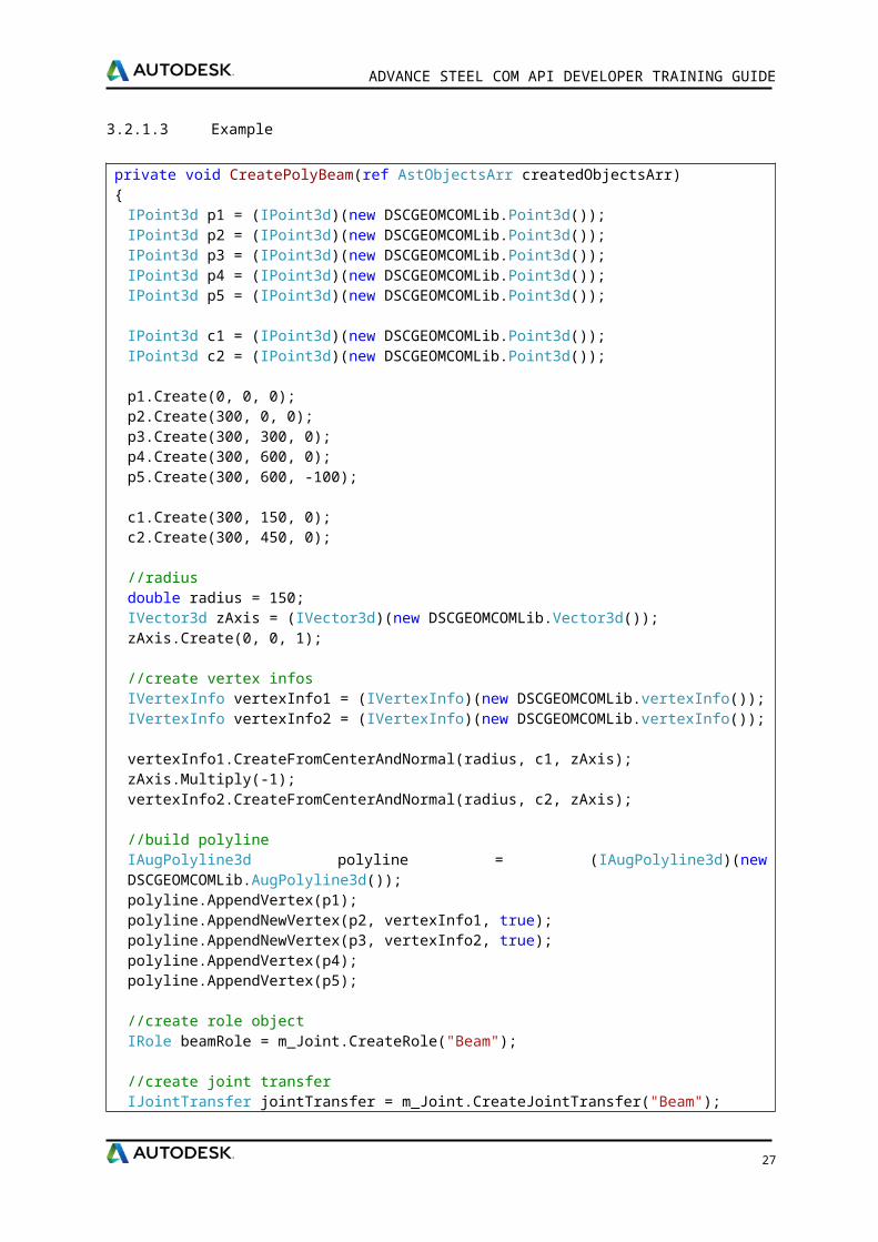
CreatePolyBeam(string sectClass, string Name, Role pRole, IAugPolyline3d line, IVector3d vecRefOrientation, IVector3d zVec) - Creates and returns a poly beam object. The beam’s className and sectionName are the internal names for the section.
section.className = value from AstorProfiles.ProfileMasterTable, column TypeNameTextsection.Name = from the definition table for className, value of column SectionNameline - defines the new poly-beam’s polylinezVec - defines the z-direction of the polyline.
3.2.1.3 Example
private void CreatePolyBeam(ref AstObjectsArr createdObjectsArr){
IPoint3d p1 = (IPoint3d)(new DSCGEOMCOMLib.Point3d());IPoint3d p2 = (IPoint3d)(new DSCGEOMCOMLib.Point3d());IPoint3d p3 = (IPoint3d)(new DSCGEOMCOMLib.Point3d());IPoint3d p4 = (IPoint3d)(new DSCGEOMCOMLib.Point3d());IPoint3d p5 = (IPoint3d)(new DSCGEOMCOMLib.Point3d());
IPoint3d c1 = (IPoint3d)(new DSCGEOMCOMLib.Point3d());IPoint3d c2 = (IPoint3d)(new DSCGEOMCOMLib.Point3d());
p1.Create(0, 0, 0);p2.Create(300, 0, 0);p3.Create(300, 300, 0);p4.Create(300, 600, 0);p5.Create(300, 600, -100);
c1.Create(300, 150, 0);c2.Create(300, 450, 0);
//radiusdouble radius = 150;IVector3d zAxis = (IVector3d)(new DSCGEOMCOMLib.Vector3d());zAxis.Create(0, 0, 1);
//create vertex infosIVertexInfo vertexInfo1 = (IVertexInfo)(new DSCGEOMCOMLib.vertexInfo());IVertexInfo vertexInfo2 = (IVertexInfo)(new DSCGEOMCOMLib.vertexInfo());
vertexInfo1.CreateFromCenterAndNormal(radius, c1, zAxis);zAxis.Multiply(-1);vertexInfo2.CreateFromCenterAndNormal(radius, c2, zAxis);
//build polyline
22
ADVANCE STEEL COM API DEVELOPER TRAINING GUIDE
IAugPolyline3d polyline = (IAugPolyline3d)(new DSCGEOMCOMLib.AugPolyline3d());polyline.AppendVertex(p1);polyline.AppendNewVertex(p2, vertexInfo1, true);polyline.AppendNewVertex(p3, vertexInfo2, true);polyline.AppendVertex(p4);polyline.AppendVertex(p5);
//create role objectIRole beamRole = m_Joint.CreateRole("Beam");
//create joint transferIJointTransfer jointTransfer = m_Joint.CreateJointTransfer("Beam");
//set joint transfer attributessetJointTransferForBeam(ref jointTransfer, eClassType.kBeamPolyClass);
//get default profilestring sectionClass, sectionSize;getDefaultProfile(0, "HyperSectionC", out sectionClass, out sectionSize);
IVector3d zVec = (IVector3d)(new DSCGEOMCOMLib.Vector3d());zVec.Create(0, 0, 1);
IVector3d vecRefOrientation = (IVector3d)(new DSCGEOMCOMLib.Vector3d());vecRefOrientation.Create(0, 1, 0);
IPolyBeam polyBeam = m_Joint.CreatePolyBeam(sectionClass, sectionSize, (AstSTEELAUTOMATIONLib.Role)beamRole, polyline, vecRefOrientation, zVec);
//Add beam to created object arrayif (polyBeam != null){ polyBeam.JointTransfer = (AstSTEELAUTOMATIONLib.JointTransfer)jointTransfer; createdObjectsArr.Add(polyBeam);}
}
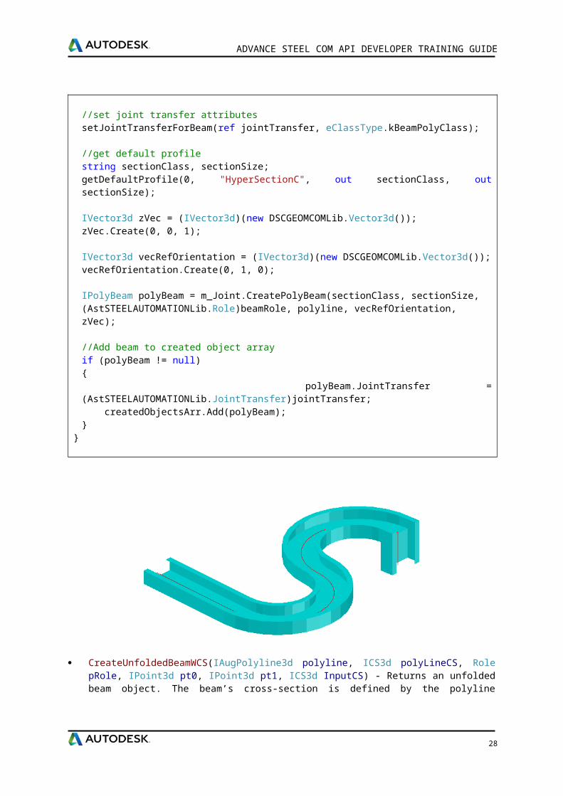
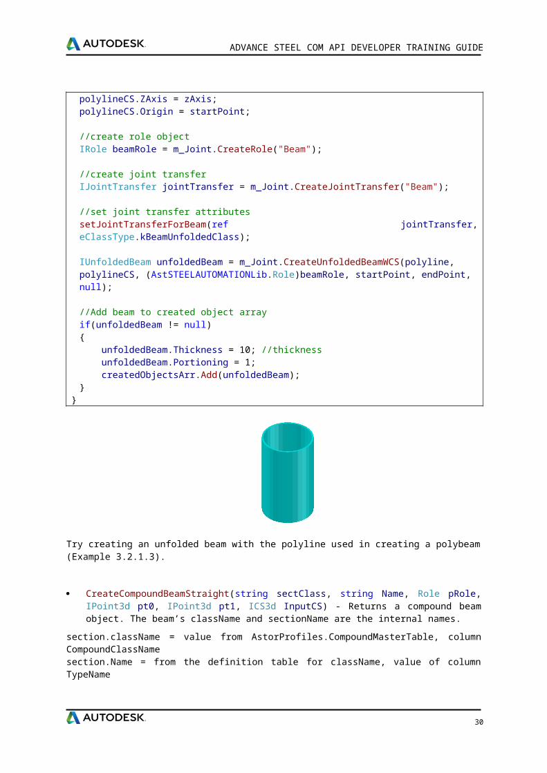
CreateUnfoldedBeamWCS(IAugPolyline3d polyline, ICS3d polyLineCS, Role pRole, IPoint3d pt0, IPoint3d pt1, ICS3d InputCS) - Returns an unfolded beam object. The beam’s cross-section is defined by the polyline together with its coordinate system and the systemline of the beam passes is defined by pt0 and pt1 points.
23
ADVANCE STEEL COM API DEVELOPER TRAINING GUIDE
3.2.1.4 Example: Create an unfolded beam
private void CreateUnfoldedBeam(ref AstObjectsArr createdObjectsArr){
//create vectorsIVector3d xAxis = (IVector3d)(new DSCGEOMCOMLib.Vector3d());IVector3d yAxis = (IVector3d)(new DSCGEOMCOMLib.Vector3d());IVector3d zAxis = (IVector3d)(new DSCGEOMCOMLib.Vector3d());
xAxis.Create(1, 0, 0);yAxis.Create(0, 1, 0);zAxis.Create(0, 0, 1);
double diameter = 300, height = 500;
//start point of beamIPoint3d startPoint = (IPoint3d)(new DSCGEOMCOMLib.Point3d());startPoint.Create(0, 0, 0);
IPoint3d pt = (IPoint3d)(new DSCGEOMCOMLib.Point3d());pt.setFrom(startPoint); xAxis.Multiply(diameter / 2);pt.Add(xAxis);xAxis.Normalize();
IVertexInfo vertexInfo = (IVertexInfo)(new DSCGEOMCOMLib.vertexInfo());vertexInfo.CreateFromCenterAndNormal(diameter / 2, startPoint, zAxis);
//build polylineIAugPolyline3d polyline = (IAugPolyline3d)(new DSCGEOMCOMLib.AugPolyline3d());
polyline.AppendNewVertex(pt, vertexInfo, false);polyline.Reinitialize();
//end point of beamIPoint3d endPoint = (IPoint3d)(new DSCGEOMCOMLib.Point3d());endPoint.setFrom(startPoint);zAxis.Multiply(height);endPoint.Add(zAxis);zAxis.Normalize();
//polyline CSICS3d polylineCS = (ICS3d)(new DSCGEOMCOMLib.CS3d());polylineCS.XAxis = xAxis;polylineCS.YAxis = yAxis;polylineCS.ZAxis = zAxis;polylineCS.Origin = startPoint;
//create role objectIRole beamRole = m_Joint.CreateRole("Beam");
//create joint transferIJointTransfer jointTransfer = m_Joint.CreateJointTransfer("Beam");
//set joint transfer attributessetJointTransferForBeam(ref jointTransfer, eClassType.kBeamUnfoldedClass);
24
ADVANCE STEEL COM API DEVELOPER TRAINING GUIDE
IUnfoldedBeam unfoldedBeam = m_Joint.CreateUnfoldedBeamWCS(polyline, polylineCS, (AstSTEELAUTOMATIONLib.Role)beamRole, startPoint, endPoint, null);
//Add beam to created object arrayif(unfoldedBeam != null){ unfoldedBeam.Thickness = 10; //thickness unfoldedBeam.Portioning = 1; createdObjectsArr.Add(unfoldedBeam);}
}
Try creating an unfolded beam with the polyline used in creating a polybeam (Example 3.2.1.3).
CreateCompoundBeamStraight(string sectClass, string Name, Role pRole, IPoint3d pt0, IPoint3d pt1, ICS3d InputCS) - Returns a compound beam object. The beam’s className and sectionName are the internal names.
section.className = value from AstorProfiles.CompoundMasterTable, column CompoundClassNamesection.Name = from the definition table for className, value of column TypeName
3.2.1.5 Example: Create a compound beam
private void CreateCompoundBeam(ref AstObjectsArr createdObjectsArr){
string sectionClass = "Compound2U", sectionName = "Default";
//create role objectIRole role = m_Joint.CreateRole("Beam");
//create joint transfer objectIJointTransfer jointTransfer = m_Joint.CreateJointTransfer("Beam");setJointTransferForBeam(ref jointTransfer, eClassType.kBeamStraightCompoundClass);
//section start, end pointIPoint3d startPoint = (IPoint3d)(new DSCGEOMCOMLib.Point3d());IPoint3d endPoint = (IPoint3d)(new DSCGEOMCOMLib.Point3d());startPoint.Create(0, 0, 0);endPoint.Create(0, 0, 500);
IVector3d yAxis = (IVector3d)(new DSCGEOMCOMLib.Vector3d());yAxis.Create(0, 1, 0);
//input CSICS3d inputCS = (ICS3d)(new DSCGEOMCOMLib.CS3d());inputCS.ZAxis = yAxis;
25
ADVANCE STEEL COM API DEVELOPER TRAINING GUIDE
//create compound beam ICompoundBeamStraight compoundBeam = m_Joint.CreateCompoundBeamStraight(sectionClass, sectionName, (AstSTEELAUTOMATIONLib.Role)role, startPoint, endPoint, inputCS);
//Add compound beam to created object arrayif (compoundBeam != null){ compoundBeam.JointTransfer = (AstSTEELAUTOMATIONLib.JointTransfer)jointTransfer; //set joint transfer createdObjectsArr.Add(compoundBeam);}
}
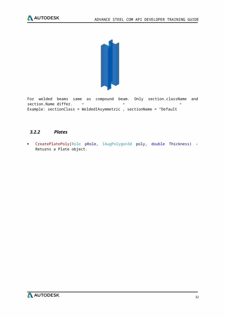
For welded beams same as compound beam. Only section.className and section.Name differ.Example: sectionClass =”WeldedIAsymmetric”, sectionName = “Default”
3.2.2 Plates
CreatePlatePoly(Role pRole, IAugPolygon3d poly, double Thickness) - Returns a Plate object.
3.2.2.1 Example: Create a polygonal plate
private void CreatePolyPlate(ref AstObjectsArr createdObjectsArr){
IVertexInfo vertexInfo = (IVertexInfo)(new DSCGEOMCOMLib.vertexInfo());
IPoint3d center = (IPoint3d)(new DSCGEOMCOMLib.Point3d());center.Create(40, 40, 0);
IVector3d zAxis = (IVector3d)(new DSCGEOMCOMLib.Vector3d());zAxis.Create(0, 0, 1);
//create vertex infodouble radius = 10;vertexInfo.CreateFromCenterAndNormal(radius, center, zAxis);
IPoint3d p1 = (IPoint3d)(new DSCGEOMCOMLib.Point3d());IPoint3d p2 = (IPoint3d)(new DSCGEOMCOMLib.Point3d());IPoint3d p3 = (IPoint3d)(new DSCGEOMCOMLib.Point3d());IPoint3d p4 = (IPoint3d)(new DSCGEOMCOMLib.Point3d());IPoint3d p5 = (IPoint3d)(new DSCGEOMCOMLib.Point3d());
26
ADVANCE STEEL COM API DEVELOPER TRAINING GUIDE
p1.Create(50, 40, 0);p2.Create(40, 50, 0);p3.Create(-50, 50, 0);p4.Create(-50, -50, 0);p5.Create(50, -50, 0);
//create polygonIAugPolygon3d polygon = (IAugPolygon3d)(new DSCGEOMCOMLib.AugPolygon3d());polygon.AppendNewVertex(p1, vertexInfo, true);polygon.AppendVertex(p2);polygon.AppendVertex(p3);polygon.AppendVertex(p4);polygon.AppendVertex(p5);
//create plate role and joint transferIRole plateRole = m_Joint.CreateRole("Plate");IJointTransfer jointTransfer = m_Joint.CreateJointTransfer("Plate");setJointTransferForPlate(ref jointTransfer);
//plate thicknessdouble plateThickness = 10;
//create plateIPlate platePoly = m_Joint.CreatePlatePoly((AstSTEELAUTOMATIONLib.Role)plateRole, polygon, plateThickness);
//Add plate to created object arrayif (platePoly != null){ //set joint transfer platePoly.JointTransfer = (AstSTEELAUTOMATIONLib.JointTransfer)jointTransfer; platePoly.Portioning = 0; createdObjectsArr.Add(platePoly);}
}
private void setJointTransferForPlate(ref IJointTransfer jointTrans){
jointTrans.ClassType = eClassType.kPlateClass;
//set here all the properties which can be modified outside the jointjointTrans.set_Attribute(eAttributeCodes.kPlateDenotation, 1);jointTrans.set_Attribute(eAttributeCodes.kPlateMaterial, 1);jointTrans.set_Attribute(eAttributeCodes.kPlateCoating, 1);jointTrans.set_Attribute(eAttributeCodes.kPlateSinglePartNumber, 1);jointTrans.set_Attribute(eAttributeCodes.kPlateMainPartNumber, 1);jointTrans.set_Attribute(eAttributeCodes.kPlateSinglePartPrefix, 1);jointTrans.set_Attribute(eAttributeCodes.kPlateMainPartPrefix, 1);jointTrans.set_Attribute(eAttributeCodes.kPlateAssembly, 1);jointTrans.set_Attribute(eAttributeCodes.kPlateItemNumber, 1);jointTrans.set_Attribute(eAttributeCodes.kPlateSinglePartDetailStyle, 1);jointTrans.set_Attribute(eAttributeCodes.kPlateMainPartDetailStyle, 1);jointTrans.set_Attribute(eAttributeCodes.kPlateNote, 1);jointTrans.set_Attribute(eAttributeCodes.kPlateSPUsedForCollisionCheck, 1);jointTrans.set_Attribute(eAttributeCodes.kPlateSPUsedForNumbering, 1);jointTrans.set_Attribute(eAttributeCodes.kPlateSPDisplayRestriction, 1);jointTrans.set_Attribute(eAttributeCodes.kPlateSPExplicitQuantity, 1);jointTrans.set_Attribute(eAttributeCodes.kPlateMPUsedForCollisionCheck, 1);
27
ADVANCE STEEL COM API DEVELOPER TRAINING GUIDE
jointTrans.set_Attribute(eAttributeCodes.kPlateMPUsedForNumbering, 1);jointTrans.set_Attribute(eAttributeCodes.kPlateMPDisplayRestriction, 1);jointTrans.set_Attribute(eAttributeCodes.kPlateMPExplicitQuantity, 1);
}
CreatePlateRectangular(Role pRole, double dLength, double dWidth, double dThickness, ICS3d cs) - Returns a plate object with the specified length, width and thickness in the specified coordinate system. The center of the plate will be in the origin of the given coordinate system.
3.2.2.2 Example: Create a rectangular plate
private void CreateRectangularPlate(ref AstObjectsArr createdObjectsArr){
IPoint3d origin = (IPoint3d)(new DSCGEOMCOMLib.Point3d());origin.Create(0, 0, 0);
IVector3d xAxis = (IVector3d)(new DSCGEOMCOMLib.Vector3d());IVector3d yAxis = (IVector3d)(new DSCGEOMCOMLib.Vector3d());IVector3d zAxis = (IVector3d)(new DSCGEOMCOMLib.Vector3d());
xAxis.Create(1, 0, 0);yAxis.Create(0, 1, 0);zAxis.Create(0, 0, 1);
ICS3d csPlate = (ICS3d)(new DSCGEOMCOMLib.CS3d());csPlate.Origin = origin;csPlate.XAxis = xAxis;csPlate.YAxis = yAxis;csPlate.ZAxis = zAxis;
double dPlateLength = 400, dPlateWidth = 200, dPlateThickness = 10;
//create rectangular plateIPlate rectangularPlate = m_Joint.CreatePlateRectangular((AstSTEELAUTOMATIONLib.Role)plateRole, dPlateLength, dPlateWidth, dPlateThickness, csPlate); //Add plate to created object arrayif (rectangularPlate != null){ //set joint transfer rectangularPlate.JointTransfer = (AstSTEELAUTOMATIONLib.JointTransfer)jointTransfer; rectangularPlate.Portioning = 0; createdObjectsArr.Add(rectangularPlate);}
}
3.2.2.3 Example: Create a folded plate using 6 plates
private void CreateFoldedPlates (ref AstObjectsArr createdObjectsArr){ IPoint3d p1 = (IPoint3d)(new DSCGEOMCOMLib.Point3d()); IPoint3d p2 = (IPoint3d)(new DSCGEOMCOMLib.Point3d()); IPoint3d p3 = (IPoint3d)(new DSCGEOMCOMLib.Point3d()); IPoint3d p4 = (IPoint3d)(new DSCGEOMCOMLib.Point3d());
p1.Create(50, 50, 0); p2.Create(-50, 50, 0);
28
ADVANCE STEEL COM API DEVELOPER TRAINING GUIDE
p3.Create(-50, -50, 0); p4.Create(50, -50, 0);
//create polygon 1 IAugPolygon3d polygon = (IAugPolygon3d)(new DSCGEOMCOMLib.AugPolygon3d()); polygon.AppendVertex(p1); polygon.AppendVertex(p2); polygon.AppendVertex(p3); polygon.AppendVertex(p4);
//create plate role and joint transfer IJointTransfer jointTransfer = m_Joint.CreateJointTransfer("FoldedPlate"); setJointTransferForPlate(ref jointTransfer); IJointTransfer jointTransfer2 = m_Joint.CreateJointTransfer("FoldedPlateRelation");
jointTransfer.ClassType = eClassType.kPlateFoldedClass; jointTransfer2.ClassType = eClassType.kPlateFoldRelationClass;
//plate thickness double plateThickness = 10;
//create first plate of folded plate IPlateFold platePolyFold = m_Joint.CreatePolyPlateFold(polygon, plateThickness);
IPoint3d p1b = (IPoint3d)(new DSCGEOMCOMLib.Point3d()); IPoint3d p2b = (IPoint3d)(new DSCGEOMCOMLib.Point3d()); IPoint3d p3b = (IPoint3d)(new DSCGEOMCOMLib.Point3d()); IPoint3d p4b = (IPoint3d)(new DSCGEOMCOMLib.Point3d()); p1b.Create(100, -45, 75); p2b.Create(100, 45, 75); p3b.Create(50, 45, 0); p4b.Create(50, -45, 0);
//create polygon 2 IAugPolygon3d polygon2 = (IAugPolygon3d)(new DSCGEOMCOMLib.AugPolygon3d()); polygon2.AppendVertex(p1b); polygon2.AppendVertex(p2b); polygon2.AppendVertex(p3b); polygon2.AppendVertex(p4b);
//create second plate of folded plate IPlateFold platePolyFold2 = m_Joint.CreatePolyPlateFold(polygon2, plateThickness);
IPoint3d p1c = (IPoint3d)(new DSCGEOMCOMLib.Point3d()); IPoint3d p2c = (IPoint3d)(new DSCGEOMCOMLib.Point3d()); IPoint3d p3c = (IPoint3d)(new DSCGEOMCOMLib.Point3d()); IPoint3d p4c = (IPoint3d)(new DSCGEOMCOMLib.Point3d()); p1c.Create(-50, -45, 0); p2c.Create(-50, 45, 0); p3c.Create(-100, 45, 75); p4c.Create(-100, -45, 75);
//create polygon 3 IAugPolygon3d polygon3 = (IAugPolygon3d)(new DSCGEOMCOMLib.AugPolygon3d()); polygon3.AppendVertex(p1c); polygon3.AppendVertex(p2c); polygon3.AppendVertex(p3c); polygon3.AppendVertex(p4c);
29
ADVANCE STEEL COM API DEVELOPER TRAINING GUIDE
IPlateFold platePolyFold3 = m_Joint.CreatePolyPlateFold(polygon3, plateThickness);
IPoint3d p1d = (IPoint3d)(new DSCGEOMCOMLib.Point3d()); IPoint3d p2d = (IPoint3d)(new DSCGEOMCOMLib.Point3d()); IPoint3d p3d = (IPoint3d)(new DSCGEOMCOMLib.Point3d()); IPoint3d p4d = (IPoint3d)(new DSCGEOMCOMLib.Point3d()); p1d.Create(-45, 50, 0); p2d.Create(45, 50, 0); p3d.Create(45, 100, 75); p4d.Create(-45, 100, 75);
//create polygon 4 IAugPolygon3d polygon4 = (IAugPolygon3d)(new DSCGEOMCOMLib.AugPolygon3d()); polygon4.AppendVertex(p1d); polygon4.AppendVertex(p2d); polygon4.AppendVertex(p3d); polygon4.AppendVertex(p4d);
IPlateFold platePolyFold4 = m_Joint.CreatePolyPlateFold(polygon4, plateThickness);
IPoint3d p1e = (IPoint3d)(new DSCGEOMCOMLib.Point3d()); IPoint3d p2e = (IPoint3d)(new DSCGEOMCOMLib.Point3d()); IPoint3d p3e = (IPoint3d)(new DSCGEOMCOMLib.Point3d()); IPoint3d p4e = (IPoint3d)(new DSCGEOMCOMLib.Point3d()); p1e.Create(-45, -100, 75); p2e.Create(45, -100, 75); p3e.Create(45, -50, 0); p4e.Create(-45, -50, 0);
//create polygon 5 IAugPolygon3d polygon5 = (IAugPolygon3d)(new DSCGEOMCOMLib.AugPolygon3d()); polygon5.AppendVertex(p1e); polygon5.AppendVertex(p2e); polygon5.AppendVertex(p3e); polygon5.AppendVertex(p4e);
IPlateFold platePolyFold5 = m_Joint.CreatePolyPlateFold(polygon5, plateThickness);
IPoint3d p1f = (IPoint3d)(new DSCGEOMCOMLib.Point3d()); IPoint3d p2f = (IPoint3d)(new DSCGEOMCOMLib.Point3d()); IPoint3d p3f = (IPoint3d)(new DSCGEOMCOMLib.Point3d()); IPoint3d p4f = (IPoint3d)(new DSCGEOMCOMLib.Point3d()); p1f.Create(100, -45, 75); p2f.Create(100, 45, 75); p3f.Create(200, 45, 50); p4f.Create(200, -45, 50);
//create polygon 6 IAugPolygon3d polygon6 = (IAugPolygon3d)(new DSCGEOMCOMLib.AugPolygon3d()); polygon6.AppendVertex(p1f); polygon6.AppendVertex(p2f); polygon6.AppendVertex(p3f); polygon6.AppendVertex(p4f);
IPlateFold platePolyFold6 = m_Joint.CreatePolyPlateFold(polygon6, plateThickness);
if ((platePolyFold != null) && (platePolyFold2 != null)) {
30
ADVANCE STEEL COM API DEVELOPER TRAINING GUIDE
IRole foldedPlateRole = m_Joint.CreateRole("FoldedPlate"); string relationRole = "Relation"; int stringerID;
//create folded plate using first plate created IPlateFolded foldedPlate =
m_Joint.CreateFoldedPlate((AstSTEELAUTOMATIONLib.Role)foldedPlateRole, (AstSTEELAUTOMATIONLib.PlateFold)platePolyFold, out stringerID);
if (foldedPlate != null) { createdObjectsArr.Add(foldedPlate); int stringerID2; PlateFoldRelation plateFoldRelation; bool ok; //extend the folded plate to the second created plate and get the Relation between the 2
plates ok = foldedPlate.ExtendBy((AstSTEELAUTOMATIONLib.PlateFold)platePolyFold2, 1,
stringerID, p1, p3b, relationRole, out stringerID2, out plateFoldRelation);
foldedPlate.JointTransfer = (AstSTEELAUTOMATIONLib.JointTransfer)jointTransfer; int stringerIDFold2 = stringerID2; //remember this to connect plate #6 if (plateFoldRelation != null) { plateFoldRelation.JointTransfer =
(AstSTEELAUTOMATIONLib.JointTransfer)jointTransfer2; createdObjectsArr.Add(plateFoldRelation); plateFoldRelation.Radius = 10; //set the radius }
if (platePolyFold3 != null) { ok = foldedPlate.ExtendBy((AstSTEELAUTOMATIONLib.PlateFold)platePolyFold3, 1,
stringerID, p2, p2c, relationRole, out stringerID2, out plateFoldRelation); if (plateFoldRelation != null) { plateFoldRelation.JointTransfer =
(AstSTEELAUTOMATIONLib.JointTransfer)jointTransfer2; createdObjectsArr.Add(plateFoldRelation); plateFoldRelation.Radius = 10; //set the radius } }
if (platePolyFold4 != null) { ok = foldedPlate.ExtendBy((AstSTEELAUTOMATIONLib.PlateFold)platePolyFold4, 1,
stringerID, p1, p2d, relationRole, out stringerID2, out plateFoldRelation); if (plateFoldRelation != null) { plateFoldRelation.JointTransfer =
(AstSTEELAUTOMATIONLib.JointTransfer)jointTransfer2; createdObjectsArr.Add(plateFoldRelation); plateFoldRelation.Radius = 10; //set the radius } }
if (platePolyFold5 != null) {
31
ADVANCE STEEL COM API DEVELOPER TRAINING GUIDE
ok = foldedPlate.ExtendBy((AstSTEELAUTOMATIONLib.PlateFold)platePolyFold5, 1, stringerID, p3, p4e, relationRole, out stringerID2, out plateFoldRelation);
if (plateFoldRelation != null) { plateFoldRelation.JointTransfer =
(AstSTEELAUTOMATIONLib.JointTransfer)jointTransfer2; createdObjectsArr.Add(plateFoldRelation); plateFoldRelation.Radius = 10; //set the radius } }
if (platePolyFold6 != null) { ok = foldedPlate.ExtendBy((AstSTEELAUTOMATIONLib.PlateFold)platePolyFold6, 1,
stringerIDFold2, p1b, p1f, relationRole, out stringerID2, out plateFoldRelation); if (plateFoldRelation != null) { plateFoldRelation.JointTransfer =
(AstSTEELAUTOMATIONLib.JointTransfer)jointTransfer2; createdObjectsArr.Add(plateFoldRelation); plateFoldRelation.Radius = 10; //set the radius } } } }}
3.2.3 Features
The basic objects (i.e., beams and plates) have available processing features. The most important processing types are:
Beam processing: coping, miter cuts, rectangular and circular contour cuts, or any type of contour.
Plate processing: corner finishes, chamfers, outer plate contours and inner contours, etc.
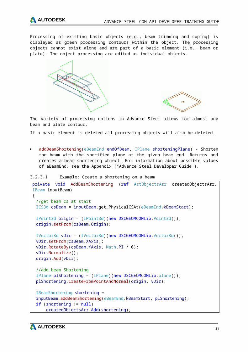
Processing of existing basic objects (e.g., beam trimming and coping) is displayed as green processing contours within the object. The processing objects cannot exist alone and are part of a basic element (i.e., beam or plate). The object processing are edited as individual objects.
The variety of processing options in Advance Steel allows for almost any beam and plate contour.
If a basic element is deleted all processing objects will also be deleted.
32
ADVANCE STEEL COM API DEVELOPER TRAINING GUIDE
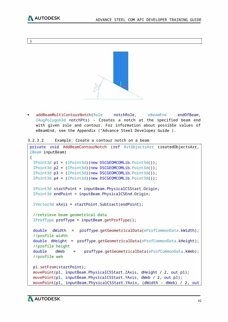
addBeamShortening(eBeamEnd endOfBeam, IPlane shorteningPlane) - Shorten the beam with the specified plane at the given beam end. Returns and creates a beam shortening object. For information about possible values of eBeamEnd, see the Appendix (“Advance Steel Developer Guide”).
3.2.3.1 Example: Create a shortening on a beam
private void AddBeamShortening (ref AstObjectsArr createdObjectsArr, IBeam inputBeam){
//get beam cs at startICS3d csBeam = inputBeam.get_PhysicalCSAt(eBeamEnd.kBeamStart);
IPoint3d origin = (IPoint3d)(new DSCGEOMCOMLib.Point3d());origin.setFrom(csBeam.Origin);
IVector3d vDir = (IVector3d)(new DSCGEOMCOMLib.Vector3d());vDir.setFrom(csBeam.XAxis);vDir.RotateBy(csBeam.YAxis, Math.PI / 6);vDir.Normalize();origin.Add(vDir);
//add beam ShorteningIPlane plShortening = (IPlane)(new DSCGEOMCOMLib.plane());plShortening.CreateFromPointAndNormal(origin, vDir);
IBeamShortening shortening = inputBeam.addBeamShortening(eBeamEnd.kBeamStart, plShortening);if (shortening != null) createdObjectsArr.Add(shortening);
}
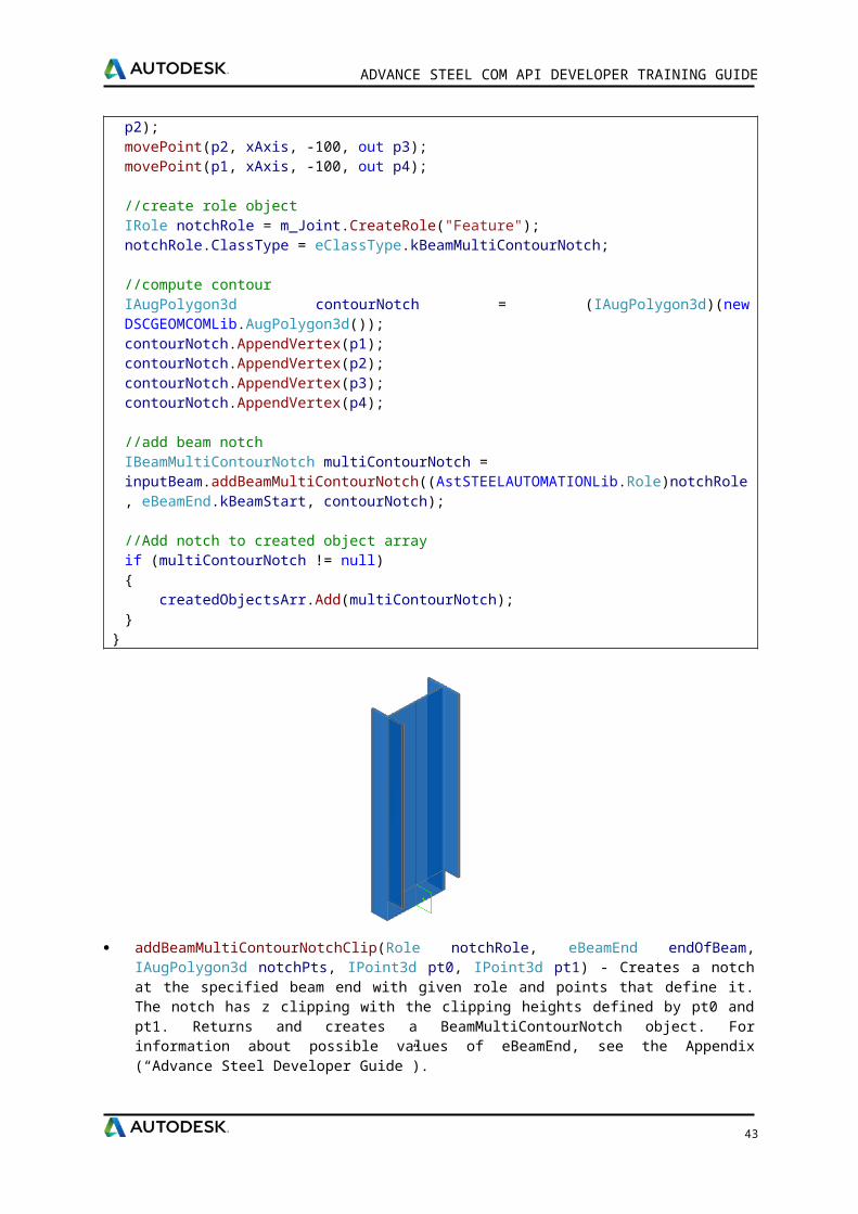
addBeamMultiContourNotch(Role notchRole, eBeamEnd endOfBeam, IAugPolygon3d notchPts) - Creates a notch at the specified beam end with given role and contour. For information about possible values of eBeamEnd, see the Appendix (“Advance Steel Developer Guide”).
3.2.3.2 Example: Create a contour notch on a beam
private void AddBeamContourNotch (ref AstObjectsArr createdObjectsArr, IBeam inputBeam){
IPoint3d p1 = (IPoint3d)(new DSCGEOMCOMLib.Point3d());IPoint3d p2 = (IPoint3d)(new DSCGEOMCOMLib.Point3d());IPoint3d p3 = (IPoint3d)(new DSCGEOMCOMLib.Point3d());IPoint3d p4 = (IPoint3d)(new DSCGEOMCOMLib.Point3d());
IPoint3d startPoint = inputBeam.PhysicalCSStart.Origin;
33
ADVANCE STEEL COM API DEVELOPER TRAINING GUIDE
IPoint3d endPoint = inputBeam.PhysicalCSEnd.Origin;
IVector3d xAxis = startPoint.Subtract(endPoint);
//retrieve beam geometrical dataIProfType profType = inputBeam.getProfType();
double dWidth = profType.getGeometricalData(eProfCommonData.kWidth); //profile widthdouble dHeight = profType.getGeometricalData(eProfCommonData.kHeight); //profile heightdouble dWeb = profType.getGeometricalData(eProfCommonData.kWeb); //profile web
p1.setFrom(startPoint);movePoint(p1, inputBeam.PhysicalCSStart.ZAxis, dHeight / 2, out p1);movePoint(p1, inputBeam.PhysicalCSStart.YAxis, dWeb / 2, out p1);movePoint(p1, inputBeam.PhysicalCSStart.YAxis, (dWidth - dWeb) / 2, out p2);movePoint(p2, xAxis, -100, out p3);movePoint(p1, xAxis, -100, out p4);
//create role objectIRole notchRole = m_Joint.CreateRole("Feature");notchRole.ClassType = eClassType.kBeamMultiContourNotch;
//compute contourIAugPolygon3d contourNotch = (IAugPolygon3d)(new DSCGEOMCOMLib.AugPolygon3d());contourNotch.AppendVertex(p1);contourNotch.AppendVertex(p2);contourNotch.AppendVertex(p3);contourNotch.AppendVertex(p4);
//add beam notchIBeamMultiContourNotch multiContourNotch = inputBeam.addBeamMultiContourNotch((AstSTEELAUTOMATIONLib.Role)notchRole, eBeamEnd.kBeamStart, contourNotch);
//Add notch to created object arrayif (multiContourNotch != null){ createdObjectsArr.Add(multiContourNotch);}
}
34

ADVANCE STEEL COM API DEVELOPER TRAINING GUIDE
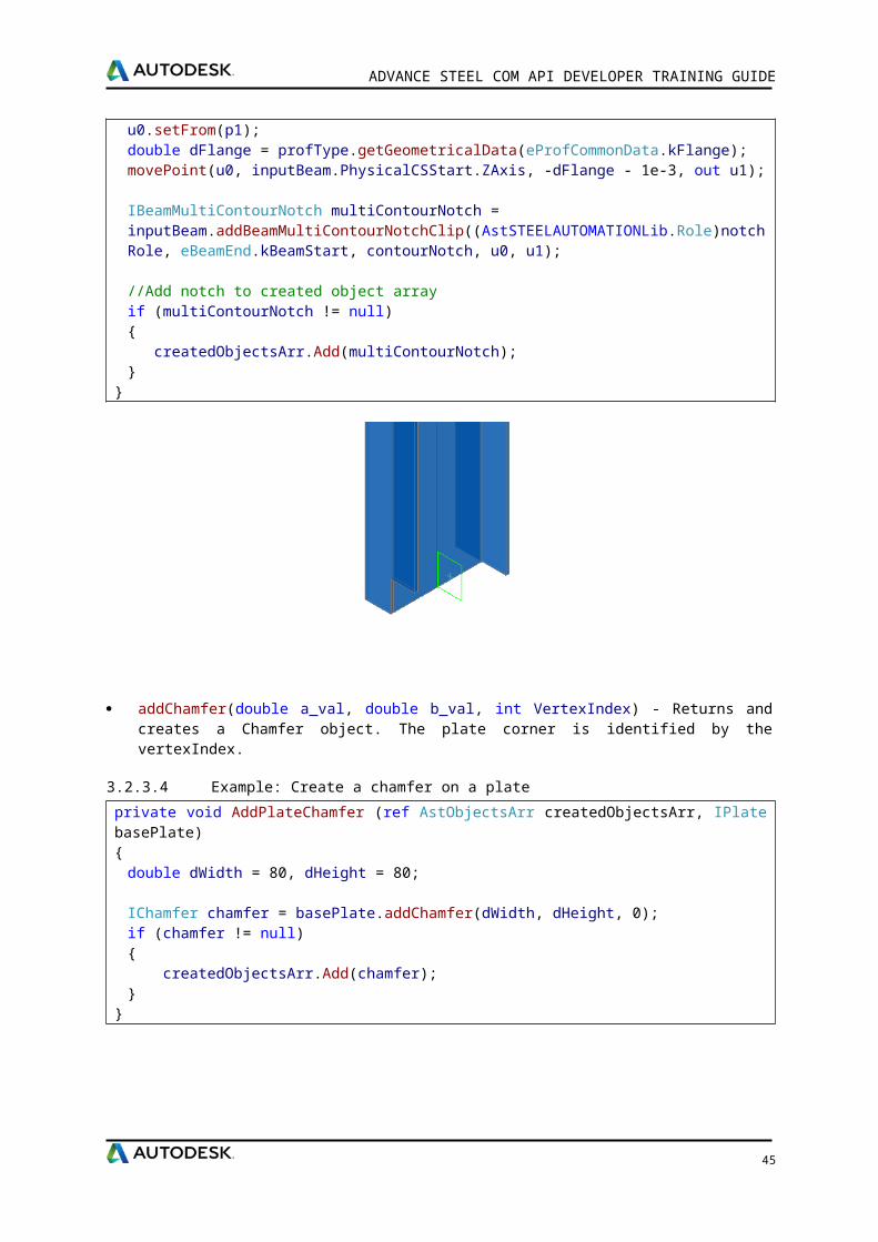
addBeamMultiContourNotchClip(Role notchRole, eBeamEnd endOfBeam, IAugPolygon3d notchPts, IPoint3d pt0, IPoint3d pt1) - Creates a notch at the specified beam end with given role and points that define it. The notch has z clipping with the clipping heights defined by pt0 and pt1. Returns and creates a BeamMultiContourNotch object. For information about possible values of eBeamEnd, see the Appendix (“Advance Steel Developer Guide”).
3.2.3.3 Example: Create a clipped contour notch on a beam
private void AddBeamContourNotchClip (ref AstObjectsArr createdObjectsArr, IBeam inputBeam){
IPoint3d p1 = (IPoint3d)(new DSCGEOMCOMLib.Point3d());IPoint3d p2 = (IPoint3d)(new DSCGEOMCOMLib.Point3d());IPoint3d p3 = (IPoint3d)(new DSCGEOMCOMLib.Point3d());IPoint3d p4 = (IPoint3d)(new DSCGEOMCOMLib.Point3d());
IPoint3d startPoint = inputBeam.PhysicalCSStart.Origin;IPoint3d endPoint = inputBeam.PhysicalCSEnd.Origin;
IVector3d xAxis = startPoint.Subtract(endPoint);
//retrieve beam geometrical dataIProfType profType = inputBeam.getProfType();
double dWidth = profType.getGeometricalData(eProfCommonData.kWidth); //profile widthdouble dHeight = profType.getGeometricalData(eProfCommonData.kHeight); //profile heightdouble dWeb = profType.getGeometricalData(eProfCommonData.kWeb); //profile web
p1.setFrom(startPoint);movePoint(p1, inputBeam.PhysicalCSStart.ZAxis, dHeight / 2, out p1);movePoint(p1, inputBeam.PhysicalCSStart.YAxis, dWeb / 2, out p1);movePoint(p1, inputBeam.PhysicalCSStart.YAxis, (dWidth - dWeb) / 2, out p2);movePoint(p2, xAxis, -100, out p3);movePoint(p1, xAxis, -100, out p4);
//create role objectIRole notchRole = m_Joint.CreateRole("Feature");notchRole.ClassType = eClassType.kBeamMultiContourNotch;
//compute contourIAugPolygon3d contourNotch = (IAugPolygon3d)(new DSCGEOMCOMLib.AugPolygon3d());contourNotch.AppendVertex(p1);contourNotch.AppendVertex(p2);contourNotch.AppendVertex(p3);contourNotch.AppendVertex(p4);
IPoint3d u0 = (IPoint3d)(new DSCGEOMCOMLib.Point3d());IPoint3d u1 = (IPoint3d)(new DSCGEOMCOMLib.Point3d());
u0.setFrom(p1);double dFlange = profType.getGeometricalData(eProfCommonData.kFlange);movePoint(u0, inputBeam.PhysicalCSStart.ZAxis, -dFlange - 1e-3, out u1);
IBeamMultiContourNotch multiContourNotch = inputBeam.addBeamMultiContourNotchClip((AstSTEELAUTOMATIONLib.Role)notchRole, eBeamEnd.kBeamStart, contourNotch, u0, u1);
//Add notch to created object arrayif (multiContourNotch != null){ createdObjectsArr.Add(multiContourNotch);
35
ADVANCE STEEL COM API DEVELOPER TRAINING GUIDE
}}
addChamfer(double a_val, double b_val, int VertexIndex) - Returns and creates a Chamfer object. The plate corner is identified by the vertexIndex.
3.2.3.4 Example: Create a chamfer on a plate
private void AddPlateChamfer (ref AstObjectsArr createdObjectsArr, IPlate basePlate){
double dWidth = 80, dHeight = 80;
IChamfer chamfer = basePlate.addChamfer(dWidth, dHeight, 0);if (chamfer != null){ createdObjectsArr.Add(chamfer);}
}
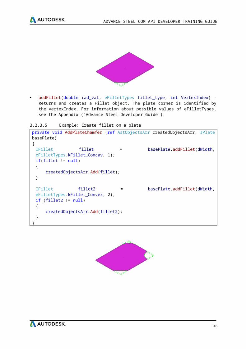
addFillet(double rad_val, eFilletTypes fillet_type, int VertexIndex) - Returns and creates a Fillet object. The plate corner is identified by the vertexIndex. For information about possible values of eFilletTypes, see the Appendix (“Advance Steel Developer Guide”).
3.2.3.5 Example: Create fillet on a plate
private void AddPlateChamfer (ref AstObjectsArr createdObjectsArr, IPlate basePlate){
IFillet fillet = basePlate.addFillet(dWidth, eFilletTypes.kFillet_Concav, 1);if(fillet != null){ createdObjectsArr.Add(fillet);}
36
ADVANCE STEEL COM API DEVELOPER TRAINING GUIDE
IFillet fillet2 = basePlate.addFillet(dWidth, eFilletTypes.kFillet_Convex, 2);if (fillet2 != null){ createdObjectsArr.Add(fillet2);}
}
3.2.4 Special parts
Objects that are not Advance Steel standard objects can be created as special parts. When Advance Steel creates drawings and bills of material with special parts they are handled like standard objects. If these objects (special parts) are to appear in the bill of material, they must be provided with Advance Steel properties.
CreateSpecialPart(Role pRole, double Scale, string BlockName, ICS3d pCS) - Creates and returns an SpecialPart object. For insertion point, the inputCS origin must be correctly specified.
3.2.4.1 Example: Create a special part
private void AddSpecialPart (ref AstObjectsArr createdObjectsArr){
double dScale = 1.0;string blockName = "agcal12"; C:\ProgramData\Autodesk\Advance Steel 2016\Shared\ Support\Symbols\agcal12.dwg
//create role objectIRole partRole = m_Joint.CreateRole("block");
IJointTransfer jointTransfer = m_Joint.CreateJointTransfer("block");jointTransfer.ClassType = eClassType.kSpecialPartWithBlock;
//create special partISpecialPart specialPart = m_Joint.CreateSpecialPart((AstSTEELAUTOMATIONLib.Role)partRole, dScale, blockName, cs);
//Add special part to created object arrayif(specialPart != null){ specialPart.JointTransfer = (AstSTEELAUTOMATIONLib.JointTransfer)jointTransfer;
37
ADVANCE STEEL COM API DEVELOPER TRAINING GUIDE
createdObjectsArr.Add(specialPart);}
}
3.2.5 Gratings
CreateStandardGrating(Role pRole, string strClass, string strSize, ICS3d cs) - Returns a grating object. The grating’s className and sectionName are the internal names.
section.className = value from AstorGratings.GratingStandardMaster, column ClassNamesection.size = from the definition table for className, value of column Name.
CreateVariablePolygonalGrating(Role pRole, string strClass, string strSize, IAugPolygon3d ptsWCS) - Returns a grating object. The grating’s className and sectionName are the internal names.
section.className = value from AstorGratings.GratingVariableMaster, column ClassNamesection.size = from the definition table for className, value of column Name.
3.2.5.1 Example: Create a grating
private void CreateGrating (ref AstObjectsArr createdObjectsArr){
//create role objectIRole gratingRole = m_Joint.CreateRole("Grating");
//create joint transferIJointTransfer jointTransfer = m_Joint.CreateJointTransfer("Grating");jointTransfer.ClassType = eClassType.kGratingClass;
string sectionClass = "Meiser_Standard";string sectionSize = "Meiser_Standard_01";
IGrating grating = m_Joint.CreateStandardGrating((AstSTEELAUTOMATIONLib.Role)gratingRole, sectionClass, sectionSize, cs);
//Add grating to created object arrayif(grating != null){ grating.JointTransfer = (AstSTEELAUTOMATIONLib.JointTransfer)jointTransfer; //set joint transfer createdObjectsArr.Add(grating);}
}
38
ADVANCE STEEL COM API DEVELOPER TRAINING GUIDE
3.2.6 Bolts, Welds and Anchors
The basic objects (i.e., beams and plates) can be connected with:
Bolt patterns (or holes only)
Welds
Anchors
These objects establish a connection between objects (e.g., beams and plates). This information is stored on the objects (i.e., beam or plate) including any bolt pattern (with its definition) or welds (with its relevant properties). Any individual element in the connection “knows” what holes, bolts, or welds it contains or with which element it is connected.
A bolt pattern can describe one or several bolts, which are automatically created in any plane together with the appropriate holes.
Changes in the bolt pattern automatically update the holes.
The tools for creating bolt patterns are used for bolts in addition to:
Holes, slotted holes, countersunk holes, blind holes, threaded holes and punch marks
Shear studs
The above are all created with their respective properties or definitions.
It is also possible to create the various hole types as part of a bolt object and a separate hole object.
Weld points are displayed as crosses in the model.
CreateBoltFinitRect(Role pRole, string Material, string norm, double wx_dim, double wy_dim, double dx_dim, double dy_dim, double nx_dim, double ny_dim, double diameter, ICS3d coordSys) - Returns a Bolt object. Create a bolt pattern of type finite, rectangular.
3.2.6.1 Example: Add bolts to a plate
private void AddBolts (ref AstObjectsArr createdObjectsArr, IPlate basePlate){
//read defaults from databaseIOdbcUtils tableUtils = (IOdbcUtils)(new DSCODBCCOMLib.OdbcUtils());
39
ADVANCE STEEL COM API DEVELOPER TRAINING GUIDE
string sBoltType = tableUtils.GetDefaultString(401, "Norm");string sBoltGrade = tableUtils.GetDefaultString(401, "Material");string sBoltAssembly = tableUtils.GetDefaultString(401, "Garnitur");double dBoltDiameter = tableUtils.GetDefaultDouble(401, "Diameter");
//Create boltsIRole boltRole = m_Joint.CreateRole("Bolt"); //role object
//create joint transfer objectIJointTransfer jointTransfer = m_Joint.CreateJointTransfer("Bolt#1");setJointTransferForBolt(ref jointTransfer);
//create bolt patternIBolt bolt = m_Joint.CreateBoltFinitRect((AstSTEELAUTOMATIONLib.Role)boltRole, sBoltGrade, sBoltType, 0, 0, 100, 100, 2, 2, dBoltDiameter, csPlate);
//Add bolt to created object arrayif (bolt != null){ //set joint transfer bolt.JointTransfer = (AstSTEELAUTOMATIONLib.JointTransfer)jointTransfer;
bolt.SetHoleTolerance(2, true); bolt.BoltSet = sBoltAssembly;
//connect objects AstObjectsArr conObj = m_Joint.CreateObjectsArray(); conObj.Add(basePlate);
bolt.Connect(conObj, eAssembleLocation.kOnSite); createdObjectsArr.Add(bolt);}
}
private void setJointTransferForBolt(ref IJointTransfer jointTrans){ jointTrans.ClassType = eClassType.kFinitrectScrewBoltPattern;
//set here all the properties which can be modified outside the joint jointTrans.set_Attribute(eAttributeCodes.kBoltPatternCommonGripLengthAddition, 1); jointTrans.set_Attribute(eAttributeCodes.kBoltPatternCommonHoleTolerance, 1); jointTrans.set_Attribute(eAttributeCodes.kBoltPatternCommonCoating, 1); jointTrans.set_Attribute(eAttributeCodes.kBoltPatternCommonDenotation, 1); jointTrans.set_Attribute(eAttributeCodes.kBoltPatternCommonAssembly, 1); jointTrans.set_Attribute(eAttributeCodes.kBoltPatternCommonItemNumber, 1); jointTrans.set_Attribute(eAttributeCodes.kBoltPatternCommonInvertAble, 1); jointTrans.set_Attribute(eAttributeCodes.kBoltPatternCommonNote, 1); jointTrans.set_Attribute(eAttributeCodes.kBoltPatternCommonIgnoreMaxGap, 1); jointTrans.set_Attribute(eAttributeCodes.kBoltPatternCommonSPUsedForCollisionCheck, 1); jointTrans.set_Attribute(eAttributeCodes.kBoltPatternCommonSPUsedForNumbering, 1); jointTrans.set_Attribute(eAttributeCodes.kBoltPatternCommonSPUsedForBillOfMaterial, 1); jointTrans.set_Attribute(eAttributeCodes.kBoltPatternCommonSPExplicitQuantity, 1); jointTrans.set_Attribute(eAttributeCodes.kBoltPatternCommonRole, 1);}
40
ADVANCE STEEL COM API DEVELOPER TRAINING GUIDE
CreateWeld(Role pRole, eWeldType Type, double Thickness, IPoint3d pLocation, ICS3d coordSys) - Returns a weld object with the specified type and thickness.
3.2.6.2 Example: Add weld between a beam and a plate
private void AddWeld (ref AstObjectsArr createdObjectsArr, IPlate basePlate, IBeam inputBeam){
//create new role objectIRole weldRole = m_Joint.CreateRole("Weld");
//create new joint transfer objectIJointTransfer jointTrans = m_Joint.CreateJointTransfer("Weld#1");
//set some attributesjointTrans.set_Attribute(eAttributeCodes.kWeldPatternThickness, 1);jointTrans.set_Attribute(eAttributeCodes.kWeldPatternAssembleLocation, 0);jointTrans.set_Attribute(eAttributeCodes.kWeldPatternSeamType, 1);
IWeld weld = m_Joint.CreateWeld((AstSTEELAUTOMATIONLib.Role)weldRole, eWeldType.kTWeld, 4, point, csAtPoint);
//Add weld to created object arrayif (weld != null){ //set joint transfer weld.JointTransfer = (AstSTEELAUTOMATIONLib.JointTransfer)jointTrans;
createdObjectsArr.Add(weld);
//connect objects AstObjectsArr conObj = m_Joint.CreateObjectsArray(); conObj.Add(inputBeam); conObj.Add(basePlate);
weld.Connect(conObj, eAssembleLocation.kInShop);}
}
41
ADVANCE STEEL COM API DEVELOPER TRAINING GUIDE
3.2.6.3 Example: Add a weld preparation on a plate
private void AddWeldPreparation (ref AstObjectsArr createdObjectsArr, IPlate basePlate){
//create weld preparationIPlateWeldingBevel weldBevel;//create weld role IRole weldRole = m_Joint.CreateRole("Feature");
int edgeIndex = 1; //which edge of platedouble xDist = 10; //x dist of weld prepdouble yDist = 5; // ydist of weld prepint plateSide = 0; // side of plate
weldBevel = platePoly.addPlateWeldingBevel((AstSTEELAUTOMATIONLib.Role)weldRole, edgeIndex, xDist, yDist, plateSide);
if (weldBevel != null) createdObjectsArr.Add(weldBevel);
}
42
4 Chapter 4Joints API
4.1 User interface
The joint with its attributes is controlled by a property sheet dialog box. This means, that this dialog box will appear during creation and modification. It exposes the joint category, the type, and all the joint attributes. One default page appears in every property sheet dialog box.The Type page contains a runtime list of all types of this category. It allows for switching between types.The Update contains a check box indicating whether this joint should be updated automatically or not (which means that the user will be informed).The rule designer has to design all other pages. This is done by implementing the GetUserPages method of the IRule. The relationship between joint type and category is represented by a table in the database AstRules.mdb. The rule designer has to create entries there in order to create this relationship.
4.2 Query method
The Query method implementation should use the provided AstUI object and get user input regarding necessary parameters or objects. The objects must be added to the Joint.InputObjects. The selected objects will become “driver objects” for the joint. Modification of the “driver objects” will instigate an update of the Joint.Also, if the rule is called using _astm4commstructasJointVB box _RuleName there is always a structural box inside the InputObjects array at the beginning of the Query method.
4.3 CreateObjects method
CreateObjects method implementation should create AS objects and add them to the CreatedObjects of the Joint. The objects can be created by using the methods of the Joint object. Once the objects are created they are automatically added to the drawing. The connection between them and the Joint object is done after they are added to the Joint.CreatedObjects. Although is possible to create objects without add them Joint.CreatedObjects is wrong to do that because in that case connection is not created and those object are “out of joint”. They will not be erased when updating the joint and other will be created.
4.4 InField/OutField methods
Advance Steel will call the OutField method every time is necessary to get the values and/or the names of the Rule attributes. Similarly will call the InField method every time is necessary for the Rule to change its current attribute values. For example calls to these methods will happen when a dwg containing a joint created with this Rule is opened/saved, when the user changes the joint parameters in the joint properties dialog box, etc.
4.5 GetUserPages method
By implementing this method you are able to specify the GUI of this Rule. This method should return handles to the created windows. The windows will become property pages for the Rule dialog box. Also here you should assign the corresponding prompts for the Rule dialog box title and for the PropertyPages titles.
ADVANCE STEEL COM API DEVELOPER TRAINING GUIDE
4.5.1.1 Example
//Set Title(From AstCrtlDb.ErrorMessages)pPropSheetData.SheetPrompt = 81309;
//First Page bitmap index(From AstorBitmaps)pPropSheetData.FirstPageBitmapIndex = 60782;pPropSheetData.ResizeOption = eGUIDimension.kStandard;
//Property Sheet 1RulePage rulePage1 = m_Joint.CreateRulePage();rulePage1.title = 88438; //Base plate layoutm_Page1 = new Page1(this);rulePage1.hWnd = m_Page1.Handle.ToInt64();pagesRet.Add(rulePage1);
4.6 GetTableName method
Return the name of the table used by the rule to run.
4.7 GetExportData
By implementing this method the Rule can specify the necessary external data for the Rule to run. Based on this information a tool is able to import/export data from/into Advance Steel databases
4.8 GetFeatureName
Must return true or false depending on license feature usage for this rule.
4.9 FreeUserPages
Release user pages
4.10 Libraries
Advance Steel provides several libraries that are intended to be used when implementing a Rule. AstSteelAutomation library – provide access to all Advance Steel dwg objects.
DSCGeomCom library – Geometry library, useful for geometric calculation (vectors, coordinates, points, parametric curves)
DSCProfilesAccesCom library – Provides access to the profiles defined used by Advance Steel.
DSCUtilFacetCom library - Provides access to the geometric body of an Advance Steel object.
DSCOdbcCom library - Provides access to data used by Advance Steel and stored in external databases.
AstControls library – Provides several controls intended to be used for the GUI of the joints.
Mainly this library has regular controls but uses database prompts (language dependent) instead of hardcoded prompts. Also this library has a Bitmap control that uses bitmaps stored in AstorBitmaps or in dll’s.
45
ADVANCE STEEL COM API DEVELOPER TRAINING GUIDE
4.11 Attributes and categories
Whenever you need to create and Advance Steel object you should define a new IRole object. This object is used to identify object from model. To create a role you need to assign a name from AstorBase database, table ModelRole corresponding to your object.
// create role objectIRole role = m_Joint.CreateRole("Haunch"); // name from AstorBase.ModelRole table
To set the user attributes of an object:role.set_Attribute(eAttributeCodes.kUserAttr1, 0);
string userAttribute = beam.get_UserAttribute(0);beam.set_UserAttribute(0, "value");
4.12 JointTransfer
This object will be passed after it is created to almost all of the methods that create Advance Steel objects. The joint transfer has mainly two “visible” applications: identify objects with identical geometry and properties and set which of the properties of joint created objects can be set by the user outside of the joint.
To define a complete joint transfer means to assign a name, the class type of the objects it will be applied to and to define which of the object’s properties will be editable outside the joint.
After setting the object class type, you have to specify which will be the editable attributes. In Visual C# syntax, this is what you have to do:
// create the joint transfer objectIJointTransfer jointTransfer = m_Joint.CreateJointTransfer("Beam");
// this joint transfer will be used when creating a straight beamjointTransfer.ClassType = eClassType.kBeamStraightClass;
//set here all the properties which can be modified outside the jointjointTransfer.set_Attribute(eAttributeCodes.kBeamMaterial, 1); //means the beam material can be set outside the jointjointTransfer.set_Attribute(eAttributeCodes.kBeamCoating, 1); //other editable properties of object with this joint transfer
If a joint transfer attribute should not be modified outside the joint (this is the default state of attributes – read only), you could use: jointTransfer.set_Attribute(eAttributeCodes.kBeamMaterial, 0); //means the beam material cannot be set outside the joint
4.13 Database Structure
Usually, the following databases are used for joint development.AstCrtlDb.mdb - used to store the localized texts the joint uses to display in AutoCAD windows or dialog box pages.AstorRules.mdb - used to store the joint "definition" records (HRLDefintion and RulesDllSigned tables) and to store any table the joint uses.The definition record in HRLDefinition requires the specification of the GUID on the ClassID column.
46
ADVANCE STEEL COM API DEVELOPER TRAINING GUIDE
4.13.1.1 Relationships
AutoCAD
AstorRules.HRLDefintionKey RuleRunNam
eInternalNam
eCategory Dll SubNameInDl
lClassID
200000
Create Plate CreatePlate CreatePlate
1000
CreatePlate {DFB7A86F-7E86-40F2-8E58-C16C776F7464}
AstorRules.RulesDllSigned tableKey FileName x86 Filename x641000 SampleJoint.dll
4.14 Joint table
Each joint can store its parameters to database. This is useful when you need to create the joint for many times. You need to configure joint one time and then save its values to database. Then when make a new joint will be created with this values. Joint table columns must be in order and with same name like members from (InField/OutField).In Query method after adding the input objects you can set parameters for joint (load from joint table or initialize with some values).
IOdbcTable odbcTable = (IOdbcTable)(new DSCODBCCOMLib.OdbcTable());odbcTable.SetCurrent("RULE_CreatePlate"); // table nameodbcTable.AddSearchCriteria(1, "Default");
//Search if joint table contain a record with "Default" name. If succeeded load values from that record.int key = (int)odbcTable.Search();if (-1 != key){ int idx = 2; m_dPlateThickness = (double)odbcTable.GetAt(idx++); //…}else{ m_dPlateThickness = 10;}
4.15 Developing a joint
4.15.1 Visual Studio solution
After starting visual studio, you need to choose new project (File / New / Project).
47
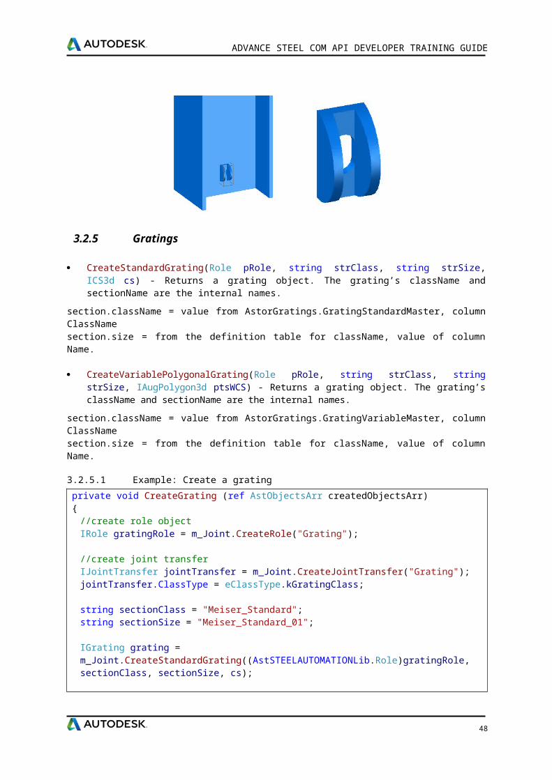
ADVANCE STEEL COM API DEVELOPER TRAINING GUIDE
The dialog below will appear. Choose Class Library
From menu Project choose Add Reference. In the Add Reference dialog box, click the Browse tab. Locate the folder where Advance Steel is installed and select the following files:
C:\Program Files (x86)\Autodesk\Advance Steel 2016\Common\Bin Interop.DSCGEOMCOMLib.dll
Interop.DSCODBCCOMLib.dll
Interop.DSCPROFILESACCESSCOMLib.dll
C:\Program Files (x86)\Autodesk\Advance Steel 2016\Common\Bin Interop.AstSTEELAUTOMATIONLib5.dll
Interop.DSCUTILFACETCOMLib.dll
48
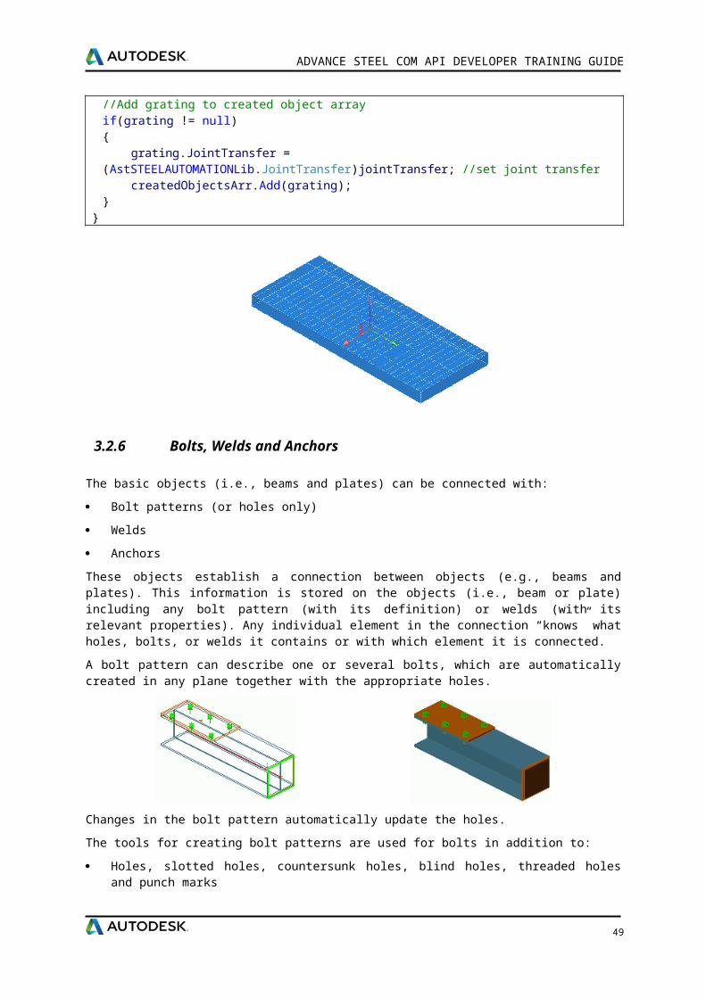
ADVANCE STEEL COM API DEVELOPER TRAINING GUIDE
Each of these libraries has a well-defined role in the joint development process and will be described in the following brief descriptions.AstSteelAutomation handles all the “core” Advance Steel functionalities. It exposes interfaces to objects that can be created with Advance Steel and also handles joint, GUI and other functionalities.
AstControls is used mainly for GUI development of joints. Several ActiveX objects have been provided with this library. For example the joint developer can link one static prompt to a CrtlDb message through a StaticDbTextControl.
DSCUtilFacetCom mainly handles the body interface. It provides access to body intersection with lines and other basic geometry interfaces.
DSCGeomCom handles basic geometry classes. This library can be used without Advance Steel. It exposes interfaces like point, vector, plane etc.
DSCOdbcCom library provides useful and easy access to Advance Steel databases. One can get prompts, defaults or easily access tables through interfaces provided by this library.
DSCProfilesAccesCom library is used to handle Proftype objects (beam profiles, userdefined and general use profiles).
At this stage the project should have only one class (default named “Class1”). This can be renamed to fit the joint’s name. Your class should inherit from IRule interface and IJointInfo.
You need to implement several methods/properties. To do that, right click on IRule and select Implement Interface.
Query methodIs the function that is passed only once when the joint is run the first time. Its role is to ask the user for input objects and set defaults.
public void Query(AstUI pAstUI){
//Filter to select only straight beamIClassFilter classFilter;classFilter = pAstUI.GetClassFilter();classFilter.AppendAcceptedClass(eClassType.kBeamStraightClass);
//Declare the input objectsAstObjectsArr inputObjectsArr = m_Joint.CreateObjectsArray();eUIErrorCodes errCode;IAstObject selectedObject = pAstUI.AcquireSingleObject(163, out errCode);
//selection incorrectif (errCode == eUIErrorCodes.kUIError)
return;
//user abort the selectionif (errCode == eUIErrorCodes.kUICancel)
return;
49
ADVANCE STEEL COM API DEVELOPER TRAINING GUIDE
//add selected object to the input objects arrayif (selectedObject != null)
inputObjectsArr.Add(selectedObject);
//add all the objects selected by the user (input objects)m_Joint.InputObjects = inputObjectsArr;
//load default parameters for jointloadDefaultValues();
}
CreateObjects contains the joint functionality. It uses the global variables declared in the declaration section and does the main work. The normal behavior when creating a new joint is to create objects in the "CreateObjects()" method and show the property pages. Remember - when you show property pages you should not force the update of the joint. For the correct functionality of a joint when a problem has appeared and the box should be red, the joint should implement the CreateObjects method as follows:
public void CreateObjects(){ bool bCreationStatus = true; AstObjectsArr createdObjectsArr = m_Joint.CreateObjectsArray();
try {
//…creation stuff….. } catch (COMException ex) { System.Diagnostics.Debug.WriteLine(ex.Message); bCreationStatus = false; } catch (System.Exception ex) { System.Diagnostics.Debug.WriteLine(ex.Message); bCreationStatus = false; }
//Set it to false will result in a joint "red box" situation. The //objects created by the joint until the error occurred will be deleted and the old objects will be available. m_Joint.CreationStatus = bCreationStatus; m_Joint.CreatedObjects = createdObjectsArr;}
50
ADVANCE STEEL COM API DEVELOPER TRAINING GUIDE
4.15.2 Create GUID
From Visual Studio menu, select (Tools/Create GUID). Select Registry Format and click Copy. Then add the following lines to you project before class name
[ComVisible(true)][Guid("paste generated GUID here")]
4.15.3 Build the program
After completing the code, you must build the project. From the Build menu, click Build Solution.
4.15.4 Add records in database
Go to C:\ProgramData\Autodesk\Advance Steel 2016\Steel\Data and open AstorRules database.
Open HRLDefinition table
Table structure:
Key
RuleRunName - The name that would appear on joint property sheet
InternalName - Command name used to call joint
Category - Joint category
Dll - Key to RulesDllSigned table
ClassID - Generated GUID
Add new record
Open RulesDllSigned table
Table structure
51
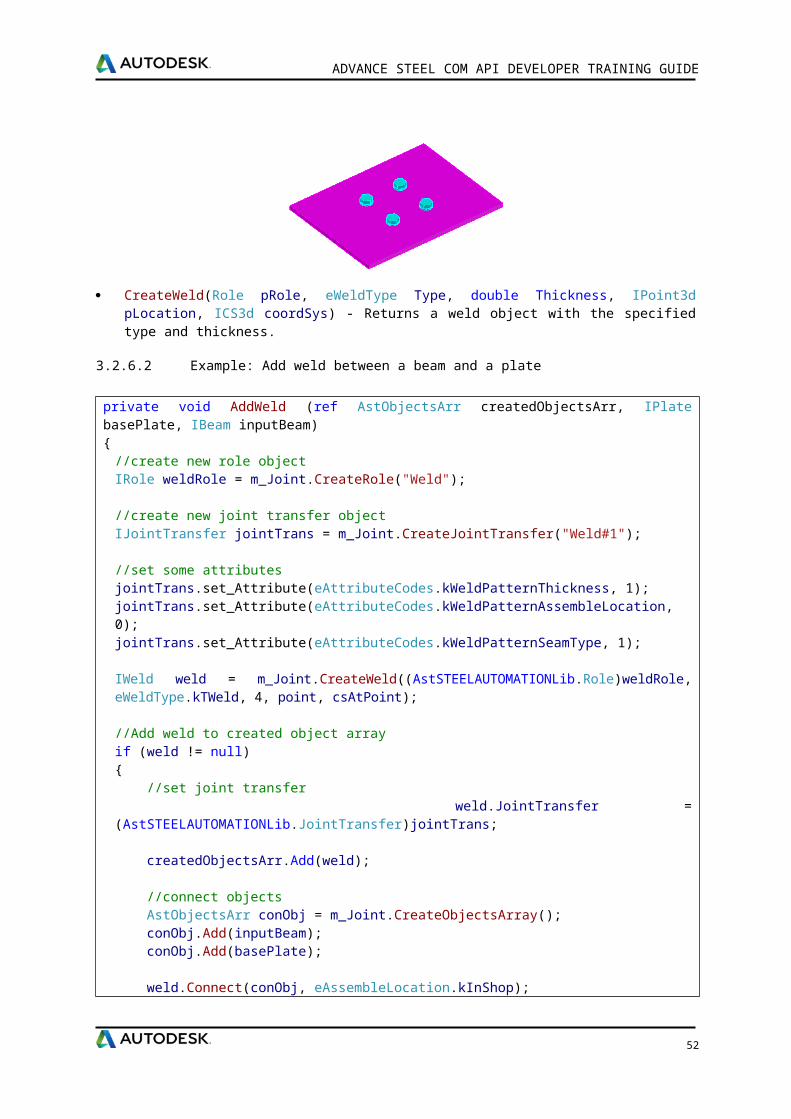
ADVANCE STEEL COM API DEVELOPER TRAINING GUIDE
Key - number from HRLDefinition.Dll
FileName x86 - DLL name for 32 bits.
FileName x64 – DLL name for 64 bits. If you compile project Any CPU this cell should be empty.
Add new record
Save and close databasePrompts are stored in AstCrtlDb database, table ErrorMessages.Go to PromptSetDefinition and set your prompt range.
When you need to add a new prompt, use numbers from this range.
4.15.5 User interface
The joint with its attributes is controlled by a property sheet dialog box. This means, that this dialog box will appear during creation and modification. It exposes the joint category, the type, and all thejoint attributes.
The rule designer has to design all pages. This is done by implementing the GetUserPages method of the IRule.
GetUserPages provides the link between the ActiveX class object created and forms created for theGUI. The joint developer is responsible for creating GUI forms for the joint. Each form represents one property sheet in the Joint Properties tab.
InField should contain persistent data reading from the dwg. In the InField function there should be calls to pFiler.readItem like:m_dPlateThickness = (double) pFiler.readItem("PlateThickness");
Please note that the “PlateThickness” string is important and should be exactly the same in the reverse operation, Outfield: pFiler.writeItem(m_dPlateThickness, "PlateThickness")
52
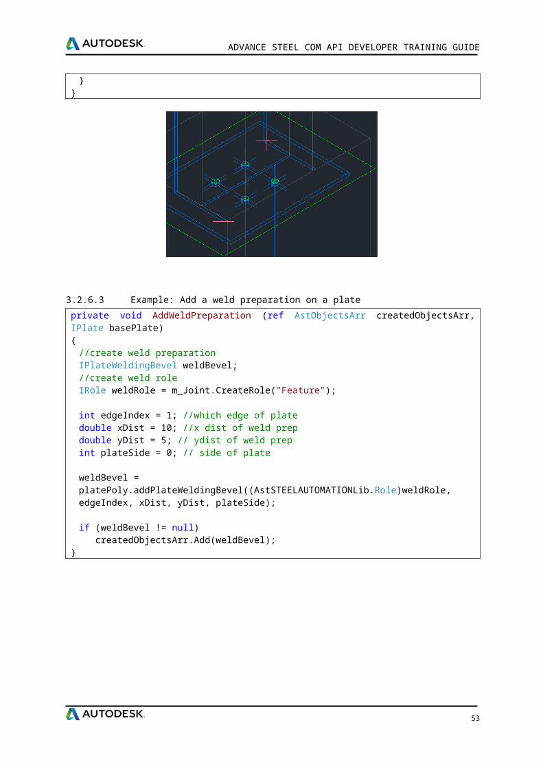
ADVANCE STEEL COM API DEVELOPER TRAINING GUIDE
4.15.6 Create first page
Right click on your project select (Add/New item/ Windows Form)
After that you need to set some properties to the form: ShowIcon: False
ShowInTaskBar: False
FormBorderStyle: None
Override CreateParams
private const int WS_CHILD = 0x40000000;
protected override CreateParams CreateParams{
get{
CreateParams cp = base.CreateParams;cp.Style = cp.Style | WS_CHILD;return cp;
}}
4.15.7 Add ActiveX control
Right click on Toolbox and select Choose Items.
53

ADVANCE STEEL COM API DEVELOPER TRAINING GUIDE
On COM Components tab select browse (*.ocx files)
Go to C:\Program Files (x86)\Autodesk\Advance Steel 2016\Kernel\Bin
Select AstControlsu.ocx
4.15.8 Control Properties
AstUnitControl
EditType: Length, Angle, Area, Weight, Volume, Double Adimensional, Integer Adimensional and String
LabelDbkey: UPS Prompt number from database(AstCrtlDb, table ErrorMessages) LabelLength: Control length
54
ADVANCE STEEL COM API DEVELOPER TRAINING GUIDE
Visible: True/False IntegerValue: Control value (use ONLY for integer type controls) DoubleValue: Control value (use ONLY for double type controls)
AstComboTableControl
LabelKey: Prompt number from database(AstCrtlDb, table ErrorMessages) LabelLength: Control length TableName: Link to table name from AstorRules database ComboIndex: Order of runname in list, starting from 0 - not the key of the table record ComboCaption: Displayed runname StringLey: Key of record for current runname - use ONLY when table has a string key LongKey: Key of record for current runname - use ONLY when table has an integer key
AstBitmapControl
Key: AstorBitmaps. BitmapIndex table
AstCheckBoxControl
CaptionKey: UPS Prompt number from database(AstCrtlDb, table ErrorMessages) Value: Control value Enable: True/False
AstBoltStandards
BoltStandard: Bolt type BoltMaterial: Bolt material BoltSet: Bolt assembly BoltDiameter: Bolt diameter LabelStandard: UPS Prompt number from database(AstCrtlDb, table ErrorMessages) LabelMaterial: UPS Prompt number from database(AstCrtlDb, table ErrorMessages) LabelBoltSet: UPS Prompt number from database(AstCrtlDb, table ErrorMessages) LabelDiameter: UPS Prompt number from database(AstCrtlDb, table ErrorMessages) ElementType: Bolt, Shear stud, Anchor LabelLength: Control length
AstProfileControl
CaptionClass: UPS Prompt number from database(AstCrtlDb, table ErrorMessages) CaptionShowHideAllSection: UPS Prompt number from database (AstCrtlDb, table
ErrorMessages) CaptionTyp: UPS Prompt number from database(AstCrtlDb, table ErrorMessages) CurrentClass: Value from AstorProfiles.ProfileMasterTable, column TypeNameText CurrentSection: From the definition table for className, value of column SectionName
AstWeldControl
LabelDbKey: Prompt number from database(AstCrtlDb, table ErrorMessages) LabelLength: Control length SelectItemByKey: Control value
4.15.9 Run joint
Compile your project
Copy output dll to C:\Program Files (x86)\Autodesk\Advance Steel 2016\Shared\Joints\Bin
Run Advance Steel
Call joint with astm4crconbyvb <jointName>
55
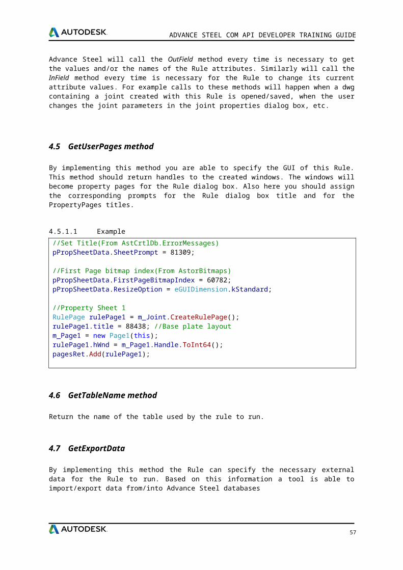
ADVANCE STEEL COM API DEVELOPER TRAINING GUIDE
56

5 Chapter 5Joints Design API
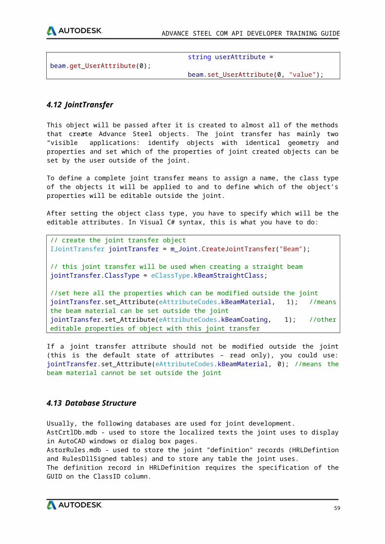
5.1.1 Implementation of a joint calculation module
We will use the following terms: joint calculation module - the module which implements the interface for communication between
Advance Steel and the program used to calculate the steel structure
calculation engine - the external calculation program
5.1.2 How it works?
A joint calculation module must be able to perform the following operations: accept input data
process input data
display results of input processing
Description of the above operations: The calculation module must be able to read joint data:
Joint parameters - values that define the configuration of the joint and are important to the calculation engine used (e.g. thickness of a plate, number of bolts, position of bolts, dimensions of a plate, etc.)
Efforts - the values should be read from Advance Steel node object defined in the proximity of the joint, but also the efforts / loadings can be entered and stored as persistent data in the calculation module itself
Processing the read data: The data processing (with an external calculation engine) must support the following actions:
Check joint - The external calculation engine must receive all important information’s from the joint and then only check if the joint configuration is correct.
Presize joint - The external calculation engine receives required data from the joint and supplies the “best configuration” for the joint, and then the joint calculation module must set the modified parameters back into the joint.
Export - The current joint configuration in the format required by the external calculation engine.
Import - The joint configuration from a previously created file by the external calculation engine.
Displaying the results: Ideally, the external calculation engine must be able to produce two types of reports (after a “check” or a “presize” operation):
Quick report - In TXT format (which will be displayed in the “Joint Design” sheet) and which contains general information’s.
Detailed report - which should be in RTF format, and should contain detailed information about the calculation results.
5.1.3 Communication interface
The joint calculation module must implement the INodeStressAppModule interface.
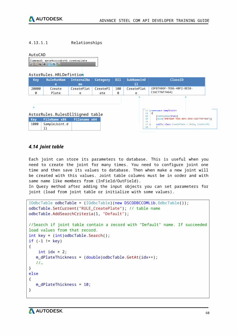
ADVANCE STEEL COM API DEVELOPER TRAINING GUIDE
5.1.4 Description of interface methods
We will describe below the main methods which need to be implemented for a calculation module and the type of actions which should be performed when each of them is called by Advance Steel.
ModuleName - You need to return from this method the internal name of the calculation module, as it was specified in the database during configuration.
Standard - Currently, from the get method you need to return “Default”.
GetExportName() -This method is called to obtain the string required to complete the text displayed in the “Joint Design” sheet on the button “Export”. Example: return “to my app” will make the “Export” button display the “Export to my app” text.
GetImportName() -This method is called to obtain the string required to complete the text displayed in the “Joint Design” sheet on the button “Import”.
GetLastReportFilename(bool bQuickReportFilename) - On the “Joint Design” sheet, after a check or presize operation, reports should be available in order to see the results of the calculation. This method must return the full path of the last created quick report and detailed report files. Depending on the values of the input parameter “QuickReportFilename” you must return true (the quick report file path) or false (the detailed report file path).
CheckJoint() - This method is called in two situations:
When you press the “Check” button from “Joint Design” sheet. When the joint updates, if the checkbox “Automatic checking” is checked.
After the check operation is finished, you need to return the joint status, depending on the results returned by the calculation engine (the joint is correctly designed, incorrectly designed or not possible to calculate).
PresizeJoint() - This method is called when the “Presize” button is pressed. You need to pass required parameters to the calculation engine, read back the results and set the new configuration of the joint, as well as returning the new status of the joint (correctly designed, incorrectly designed or impossible to calculate).
ImportJoint()/ExportJoint () - Each method is called when the “Export”, respectively “Import” buttons are pressed. In case of export: you need to save the current joint configuration in a format which can be read by the calculation engine. In case of import: you need to set the joint parameters to the corresponding values, depending on the imported data, which has been created previously by the calculation engine. You must to display the “Save As…” or “Open…” dialogs when the methods are called.
GetUserPages(RulePageArray pagesRet, PropertySheetData pPropSheetData) - Called when the “Torsors” button is pressed – you need to prepare the dialogs which display the efforts/loadings from the Node (if it exists) and also allow the creation of new sets of efforts/loadings.
GetUserTorsorsPage(RulePage pageRet) - Called when the “Joint Design” sheet is displayed. You need to prepare the display of the “torsor” values on the “Joint Design” sheet.
GetUserSettingsPages(RulePageArray pagesSettingsRet, PropertySheetData pPropSheetData) - Called when the “Settings” button is pressed. You need to prepare the dialogs which allow the setting of other data required by the calculation engine (other than efforts and joint parameters) - like detailed report format (TXT, RTF …), reports creation (only in certain conditions, like calculation failed), etc…
59
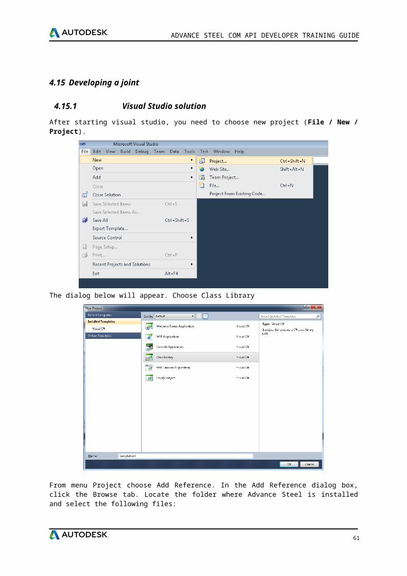
ADVANCE STEEL COM API DEVELOPER TRAINING GUIDE
In addition to the implementation of the INodeStressAppModule interface, the joint calculation module requires the use of an object of IStressModuleJoint type.
Methods and properties available in IStressModuleJoint interface: InputObjects - obtain the array of input objects for the joint.
CreatedObjects - obtain the array of objects created by the joint.
CreateObjectsArray - create an array for storing objects.
UseDetailedTorsors - check if all efforts/loadings should be used in calculation, or only the maximum torsor is to be considered.
Units - get current Advance Steel units.
JointName - identifies the internal name of the joint currently being calculated
GetJointParam - obtain the specified parameter value from the joint (requires the use of a string that identifies the parameter - must be the same string used in the joint OutField/InField methods).
SetJointParam - set the specified joint parameter value - you need to use this after a presize or import operation (requires the use of a string that identifies the parameter - must be the same string used in the joint OutField/InField methods).
GetJointNSAModuleSpecificData - retrieve the value of a persistent parameter set by the calculation module (similar to the joint InField functionality).
SetJointNSAModuleSpecificData - set the value of a persistent parameter for the calculation module (similar to the joint OutField functionality).
GetNodeInputObjectIds - retrieve the IDs assigned to the specified input object (one or two IDs) - when a Node is defined.
GetNodeEffortSetsLengthAtId - retrieve the number of efforts sets for the specified ID - when a Node is defined.
GetNodeEffortSetAtId - retrieve, from the specified ID, the effort set with the specified index - when a Node is defined.
GetJointNSAModuleLoadingCases - retrieve the efforts/loadings defined in the calculation module.
SetJointNSAModuleLoadingCases - save the new set of efforts/loadings for the calculation module.
CreateJointEffort - create a new object for storing one effort.
CreateJointEfforts - create an object for storing efforts.
CreateJointLoadingCase - create one loading object.
CreateJointLoadingCases - create an array of loadings.
GetModuleOutputFileName - get the name of the file for saving current joint data (full path, supplied by Advance Steel - contains joint name and joint ID).
GetJointUserId - get the ID of this joint (unique in the dwg).
CreateRulePage - create an IRulePage object (for dialogs).
60
ADVANCE STEEL COM API DEVELOPER TRAINING GUIDE
5.1.5 Database Structure
In order to attach a joint calculation module to a joint, you need to create records for the calculation module in the AstorJointsCalculation.mdb database.
JointInternalName - Key to AstorRules.HRLDefinition table
NSAModuleInternalName - Key to AstorJointsCalculation.NSAModuleDefinition
DefaultModule - 1
ClassID - GUID from “CreatePlateDesign” class
5.1.5.1 Relationships
AstorJointsCalculation.NSAModule tableKey
StressAnalysisCodeID
JointInternalName
NSAModuleInternalName
DefaultModule
1 0 CreatePlate CreatePlateNSAModule 1
AstorJointsCalculation.NSAModuleDefinition tableKey ModuleRunName InternalName NSAModuleDll ClassID
1 My module CreatePlateNSAModule 12 {C64ECF63-D01C-451F-B0E0-E3F85DFAC05E}
AstorJointsCalculation.NSAModuleDllSigned tableKey FileName x86 FileName x6412 SampleDesign.dll
5.2 Developing a joint design
Use same bat from developing joint section.
Create new Project
Choose Class Library
Add References
Interop.AstSteelAutomationLib5 Interop.DSCGEOMCOMLib Interop.DSCRootsCOMLib DotNetRoots
Implement INodeStressAppModule interface
61
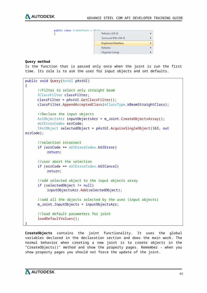
ADVANCE STEEL COM API DEVELOPER TRAINING GUIDE
CheckJoint method contains the joint design functionality.
public eJointStatus CheckJoint(){
eJointStatus ret = eJointStatus.JointSupported;
//report formatint nReportFormat = (int)getJointNSAModuleSpecificData(m_joint, this, "ReportFormat", 0);
//get effortsList<double> dM, dN, dV;List<string> sCaseName;getEfforts(m_joint, m_joint.GetJointNSAModuleLoadingCases(this),
m_joint.UseDetailedTorsors, out dM, out dN, out dV, out sCaseName);
//read some values from jointbool bModifiable = false;double dPlateThickness = (double)m_joint.GetJointParam("PlateThickness", ref bModifiable);double dPlateLength = (double)m_joint.GetJointParam("PlateLength", ref bModifiable);double dPlateWidth = (double)m_joint.GetJointParam("PlateWidth", ref bModifiable);
return ret;}
Generate GUID
[ComVisible(true)] [Guid("C64ECF63-D01C-451F-B0E0-E3F85DFAC05E")]
After completing the code, you must build the project. From the Build menu, click Build Solution.
Go to C:\ProgramData\Autodesk\Advance Steel 2016\StressAnalysis\Data and open AstorJointsCalculation database.
Open NSAModule table and add new record
Open NSAModuleDefinition table and add new record
Open NSAModuleDllSigned table and add new record
Save and close database
Compile your project
Copy output dll in C:\Program Files (x86)\Autodesk\Advance Steel 2016\Shared\Joints\Bin\
Run Advance Steel
62
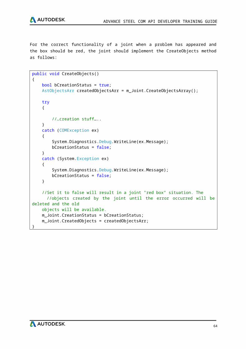
ADVANCE STEEL COM API DEVELOPER TRAINING GUIDE
Call joint. Now you should see a new Page “Joint Design”
63
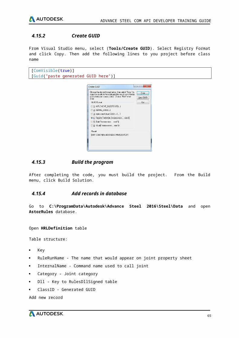
6 Chapter 6Advance Steel Scripting Possibilities
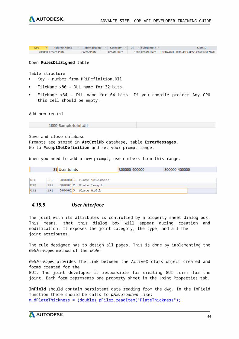
6.1 Advance Steel Lisp API
See Advance Steel Visual Lisp Script Language manual
6.2 Numbering scripts
Before creating the project documentation (drawings, BOMs, etc.), the structure must be numbered. The basis for numbering is finding identical parts that should have the same mark.
Each object in Advance Steel has two part marks: a Single Part number and an Assembly part number. The basis for numbering is finding identical parts that should have the same mark.
During the numbering process, the numbering tool: Analyzes the model to identify equal parts and determine quantities.
Analyzes the relationship between parts to identify assemblies and main parts.
Assigns part and assembly numbers to objects in the structure.
Single Parts and Assemblies are automatically numbered for the entire model.The elements are compared by geometry, material properties, coating, and commodity (and behavior). The properties name and lot/phase are not considered for numbering. The Model Role is used by the prefix tool to assign prefixes but it is not used directly for numbering.
6.2.1 Workflow
At first, all structural parts should be numbered so start with single part marks.
The program then determines the assembly marks for parts connected in the shop. The biggest part of an assembly is the main part and will get an assembly mark and all other parts are considered attached and will have a single part mark.
Standard parts are numbered using additional options. Any part in the current model that matches a Standard Part in the template will get the same mark (single part mark or assembly mark, according to the situation).
During the numbering process beams and then plates are the first to be numbered. In each case, the group with the most elements will get the lowest number.
6.2.2 Numbering standard parts
A Standard Part Template makes a particular item or group of items have assigned a fixed part mark.Standard parts are created in a template model using normal Advance Steel functionalities and then assigned required part marks. During a numbering process objects are compared to detect identical parts. Any part of the current model that matches a Standard Part in the template will get the same mark. The standard part templates can be linked to the current project. The folder C:\ProgramData\Autodesk\Advance Steel 2016\Shared\StandardPartTemplate contains the standard part models. The available templates are listed on the Standard part template tab of the Numbering dialog box.
The standard part template can be reused for any other project or new standard part templates can be created if necessary.
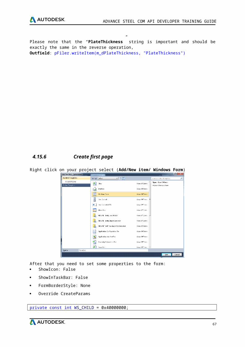
ADVANCE STEEL COM API DEVELOPER TRAINING GUIDE
6.2.3 Numbering prefix
In a steel structure, to make the difference between single parts and assemblies, prefixes can be used to have distinct part marks.
Prefixes can be manually assigned, separately for parts and assemblies, or automatically assigned during the numbering process, according to the model role of the model elements (e.g.: beam, column, rafter, plate, etc.).
6.2.4 Main part of an assembly
Main part assignment is either performed manually or by the numbering process using Create main part of assembly that automatically detects attached parts. Alternatively, during assembly numbering, the biggest part automatically becomes the main part.
6.2.5 Numbering methods
There are few methods for numbering available in Numbering - General tab.
The first three numbering methods assign fixed numbers to the objects. There will be no link between the assigned element number and the drawing the piece is detailed on.
SP: 1000, 10001, ...; MP: 1,2,3: The Single parts and the Main parts are numbered starting with the defined value.
SP: 1000, 10001, ...; MP: 1000, 1,2,3: The Single parts and the Main parts are numbered starting with the defined value. The standalone parts are numbered using same numbering rule defined for the Single parts.
SP: 1/1 ..1/32..3/32;MP:1/1..: The Single parts and the Main part mark contains the number of identical parts.
With drawing number: Assigns an internal number to each object. During the detail creation, the internal number will be changed to the drawing number the element is detailed on. At drawing creation, the first part gets the prefix a001, then b001, etc.
These methods are implemented in VBScript. The code can be found in C:\ProgramData\Autodesk\Advance Steel 2016\Kernel\Data database AstorKernelEnvironment.mdb, NumberingMethod table.
67
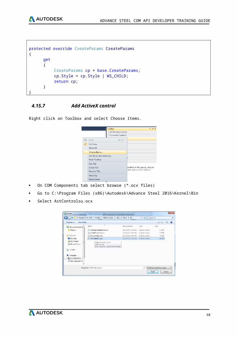
ADVANCE STEEL COM API DEVELOPER TRAINING GUIDE
The IPositionMarkCreator interface properties/methods are interrogated to get information about numbering options from user dialog.
Methods and properties available in IPositionMarkCreator interface
MarkProcessType - Gets or sets the process type (kSinglePart, kMainPart, kPreliminaryPart)
Single part marks: All structural parts are numbered.
Assembly marks: The program determines the assembly marks for parts connected in the shop. The biggest part of an assembly is the main part and gets an assembly mark and all other parts are considered attached and will have a single part mark.
UseTemplateType – Gets or sets template type.
CurrentObject – Gets or sets the object to be numbered.
IsUniqueInTheModel – Checks if a part number is unique in the model.
GetAsInternalFormat – Formats a part number. (Ex: 1001 -> #internalnumber1001)
IsInternalNumber – Checks if a part number is an internal number.
GetStartAtForSingleParts – Returns the start number for the single parts numbering. By default, single parts marks begin with 1000 and increase by increments of 1.
GetStartAtForMainParts – Returns the start number for main parts.
GetDeltaForSingleParts – Returns the increment for the single parts numbering.
GetDeltaForMainParts – Returns the increment for the main parts numbering.
UpdateStartAtForSingleParts – Update the start number for the single parts numbering.
UpdateStartAtForMainParts – Update the start number for the main parts numbering.
UpdateDeltaForSingleParts – Update the increment for the main parts numbering.
UpdateDeltaForMainParts – Update the increment for the main parts numbering.
GetNextNumber – Returns the next number for numbering.
GetStartAtForSinglePartsWithPrefix – Returns the current start number for the single parts numbering with prefix.
GetStartAtForMainPartsWithPrefix – Returns the current start number for the main parts numbering with prefix.
UpdateStartAtForSinglePartsWithPrefix – Update the current start number for the single parts numbering with prefix.
UpdateStartAtForMainPartsWithPrefix – Update the current start number for the main parts numbering with prefix.
UpdateNumber – Update the number for an IEqualPartObject.
GetStartAtForPreliminaryPartsWithPrefix – Returns the current start number for the preliminary parts with prefix.
GetDeltaForPreliminaryParts – Returns the increment for the preliminary parts numbering.
GetStartAtForPreliminaryParts – Returns the start number for the preliminary parts numbering.
68
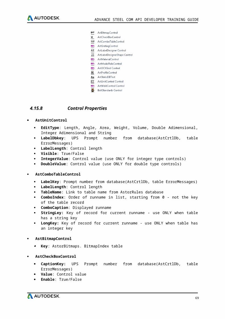
ADVANCE STEEL COM API DEVELOPER TRAINING GUIDE
UpdateStartAtForPreliminaryPartsWithPrefix – Update the start number for the preliminary parts numbering with prefix.
UpdateStartAtForPreliminaryParts – Update the start number for the preliminary parts numbering.
UpdateDeltaForPreliminaryParts – Update the increment for the preliminary parts numbering.
AddZerosToPartMark – Adds zeros to part mark.
Your script must implement the getNumber method.
Example:
''''''''''''''''''''''''''''''''''''''''''''''''''''''''''''''''''''''''''''''''''''''Script used by Numbering process'''''''''''''''''''''''''''''''''''''''''''''''''''''''''''''''''''''''''''''''''''''Function getNumber(EqualPartObject) Number = -1 If PositionMarkCreator.MarkProcessType = kSinglePart Then 'Calculate the single part number StartAt PositionMarkCreator.GetStartAtForSinglePartsWithPrefix( EqualPartObject.Type, EqualPartObject.SinglePartPrefix) Delta = PositionMarkCreator.getDeltaForSingleParts(EqualPartObject.Type)
Number = StartAt Number = PositionMarkCreator.AddZerosToPartMark(Number)
Do Until PositionMarkCreator.isUniqueInTheModel(kBoth, EqualPartObject.SinglePartPrefix & Number) StartAt = StartAt + Delta Number = StartAt Number = PositionMarkCreator.AddZerosToPartMark(Number) Loop PositionMarkCreator.UpdateStartAtForSinglePartsWithPrefix EqualPartObject.Type, EqualPartObject.SinglePartPrefix, StartAt+Delta End If getNumber = Number
End Function
6.3 Drawing styles scripts
6.3.1 Overview
Upon building a 3D model, dimensioned and labeled 2D general arrangement and shop drawings can be automatically created. The drawings are created in separate DWG files from the model, however they are linked to track changes.The model knows which drawings have been linked and checks if these drawings still correlate. Thus, the drawings can be updated after any model modifications. This link is ‘one way’ and changing a drawing will not modify the model.A drawing may consist of several linked details, which are individual Advance objects with their own properties.
Advance offers a variety of drawing styles for general arrangement drawings, sections, and shop drawings in various designs. The drawing style is a group of instructions used to create a detail
69
ADVANCE STEEL COM API DEVELOPER TRAINING GUIDE
drawing and defines the selection of the elements that are to be displayed including labeling and dimensioning preferences.
The drawing styles provide the option to automatically create drawings and to modify the layout exactly to user requirements. Drawing styles are used in a similar way to standard CAD dimension styles, line styles, etc. The styles are defined with various settings (e.g., parts to be displayed, view, dimensions, labeling, representation etc.) in MS Access tables (libraries).
Scripts are implemented in VBScript. The code can be found C:\ProgramData\Autodesk\Advance Steel 2016\Steel\Data database AstorDetails.mdb, DetailStyleMapItems table.
Your script must implement the checkElement method.
Example:
'Script to filter " C" profiles onlyFunction checkElement(Obj) checkElement = False 'Be sure the object is a beam. If Obj.Type = kBeamStraightClass OR Obj.Type = kBeamPolyClass Then 'Get the name of the profile and convert it to upper letters. ProfName = Ucase(Obj.getProfType.getSectionName) 'Check if the name contains "C". If InStr(ProfName, "C") Then checkElement = True End If End IfEnd Function
70

ADVANCE STEEL COM API DEVELOPER TRAINING GUIDE
6.4 Drawing process scripts
6.4.1 Overview
To accelerate the drawing creation by automatically assigning drawing styles and layouts for the selected parts, drawing processes are used.
Drawing processes automatically create part drawings (using appropriate drawing styles) and arrange the created details within a drawing (.dwg) or across several drawings. A drawing process will step through all the selected objects, choose a suitable Drawing Style and create a drawing of the object, then move on to the next object. In this way many drawings of many objects can be created quickly and easily.
A drawing process includes a number of sub-processes:
Selection of parts
Sorting, selection of an appropriate drawing style based on the object type and model role
Selection of the appropriate prototype
Rules for arranging details on the sheet: several drawing scales are tested to find the best fit on the sheet. The actual scales tried are defined within the Process. If multiple sizes are allowed all scales will be tried on the smallest sheet first then all scales on the next sheet size and so on working up. If a single sheet size is selected and none of the scales fit the border the views will be still created at the smallest scale on the given sheet.
Rules to attach new sheets.
Automatically naming the file
Scripts are implemented in VBScript. The code can be found in the C:\ProgramData\Autodesk\Advance Steel 2016\Kernel\Data database AstorDetailsBase.mdb, DetObjQualifierFilter table.
Your script must implement the checkElement method.
Example:
'Returns true for bolts connected On ShopFunction checkElement(Obj) bOnShop = False If Obj.IsKindOf(kScrewBoltPattern) = True Then 'See if bolt is On shop If Obj.AssemblyLocation = kInShop Then bOnShop = True End If End If checkElement = bOnShopEnd Function
71

ADVANCE STEEL COM API DEVELOPER TRAINING GUIDE
6.5 BOM pre-processing using XSLT
From the model information an extract is created which is used to generate reports. The model extract can be pre-processed using XSL transformation. XSLT files are stored in C:\ProgramData\Autodesk\Advance Steel 2016\Shared\Support\Transformation folder. In order to pre-process the model extract xml file user has to create the XSL file and save it in the Transformation folder, assign the XSLT file to the report template in BOM Editor and save the template. When a report is generated the XSL transformation is applied to the selected model extract and the resulted extract is then used by the BOM tool.Example: The Cladding list report template uses Cladding list.xslt in order to preprocess the cladding profiled which contain additional information (set via Cladding joint dialog) about the inside/outside coating, number of bolts needed to fix the profile.
72
ADVANCE STEEL COM API DEVELOPER TRAINING GUIDE
73