Embed Size (px)
Citation preview
8/3/2019 Adrian Down- Particle Beam Waist Location in Plasma Wakefield Acceleration: Introduction and Background
http://slidepdf.com/reader/full/adrian-down-particle-beam-waist-location-in-plasma-wakefield-acceleration 1/12
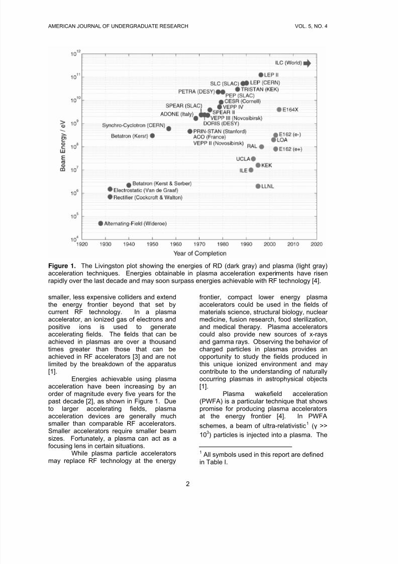
AMERICAN JOURNAL OF UNDERGRADUATE RESEARCH VOL. 5, NO. 4
Particle Beam Waist Location in Plasma WakefieldAcceleration: Introduction and Background
Adrian Down‡
Department of PhysicsUniversity of CaliforniaBerkeley, California 94720-7300 USA
Received: September 27, 2006 Accepted: January 2, 2007
ABSTRACT
The role of beam waist location in interactions between a plasma and a particle beam is not yetfully understood. Nonlinear effects with the plasma make an analysis of such interactions difficult.Five simulations are presented in this report, with the waist location of a beam of ultra-relativisticelectrons propagating through one meter of self-ionized lithium plasma. The simulationparameters are chosen to model the recent experiment 167 at the Stanford Linear Accelerator,
relevant to the design of future plasma wakefield accelerating afterburners. It is found that beamsfocused near the point of entry into the plasma propagate further into the plasma and acceleratewitness particles to a greater maximum energy before disintegrating. These results couldindicate that ion channel formation is dependent on the drive beam waist location and that theplasma accelerating medium can have an observable effect on the focusing of the drive beam.
I. INTRODUCTION
Experiments using high energyparticle accelerators have led to discoveriesabout the structure of matter, astrophysicalprocesses, and the early history of theuniverse [1]. Future colliders that accelerateparticles to higher energies could provideinsight into the nature of mass and theunification of the fundamental forces of nature [2]. Constructing higher energyparticle accelerators could contribute toresearch in many branches of physics.Particles accelerated to lower energy areuseful for other purposes and are animportant source of radiation for researchand medical devices.
In conventional colliders, particlesare accelerated using electric fieldsproduced by microwave radiation. Thesefields travel synchronously with the particles
to be accelerated [2]. The energy of theaccelerated particles is a function of thestrength of the accelerating field and thedistance over which the field acts.
The fields that can be achieved bythis radio frequency (RF) technology arefundamentally limited by the structuralintegrity of the collider apparatus. RFaccelerating fields are generated in metal
devices called slow wave cavities.Increasing the field in these cavities far beyond levels employed in current highenergy colliders leads to electricalbreakdown within the cavities and ionizationof the materials with which the cavities areconstructed [1].
Because the fields achievable usingRF technology are limited, the energies thatcan be obtained with this technology havethus far been increased by increasing thedistance over which the accelerating fieldacts. The highest energy RF collider iscurrently the Large Hadron Collider under construction at CERN [2] and scheduled tobe completed in 2007. At this enormousfacility, protons will circle a loop 8.7 km inradius before colliding with 7 TeV [Teraelectron volts or 1012 eV] of energy.Continuing to advance the energy frontier of RF accelerators by increasing the size of the
devices faces shortfalls of funding andresources. Plans for a SuperconductingSuper Collider that would be 28 km indiameter and cost $8 billion to constructwere cancelled by the U.S. Congress in1993, and a proposed linear collider 30 kmin length has yet to receive funding [3].
New techniques for acceleratingparticles using plasmas could soon produce
1
8/3/2019 Adrian Down- Particle Beam Waist Location in Plasma Wakefield Acceleration: Introduction and Background
http://slidepdf.com/reader/full/adrian-down-particle-beam-waist-location-in-plasma-wakefield-acceleration 2/12
AMERICAN JOURNAL OF UNDERGRADUATE RESEARCH VOL. 5, NO. 4
Figure 1. The Livingston plot showing the energies of RD (dark gray) and plasma (light gray)acceleration techniques. Energies obtainable in plasma acceleration experiments have risenrapidly over the last decade and may soon surpass energies achievable with RF technology [4].
smaller, less expensive colliders and extendthe energy frontier beyond that set bycurrent RF technology. In a plasmaaccelerator, an ionized gas of electrons andpositive ions is used to generateaccelerating fields. The fields that can beachieved in plasmas are over a thousandtimes greater than those that can beachieved in RF accelerators [3] and are notlimited by the breakdown of the apparatus[1].
Energies achievable using plasmaacceleration have been increasing by an
order of magnitude every five years for thepast decade [2], as shown in Figure 1. Dueto larger accelerating fields, plasmaacceleration devices are generally muchsmaller than comparable RF accelerators.Smaller accelerators require smaller beamsizes. Fortunately, a plasma can act as afocusing lens in certain situations.
While plasma particle acceleratorsmay replace RF technology at the energy
frontier, compact lower energy plasmaaccelerators could be used in the fields of materials science, structural biology, nuclear medicine, fusion research, food sterilization,and medical therapy. Plasma acceleratorscould also provide new sources of x-raysand gamma rays. Observing the behavior of charged particles in plasmas provides anopportunity to study the fields produced inthis unique ionized environment and maycontribute to the understanding of naturallyoccurring plasmas in astrophysical objects[1].
Plasma wakefield acceleration(PWFA) is a particular technique that showspromise for producing plasma acceleratorsat the energy frontier [4]. In PWFA
schemes, a beam of ultra-relativistic1 (γ >>
103) particles is injected into a plasma. The
1 All symbols used in this report are definedin Table I.
2
8/3/2019 Adrian Down- Particle Beam Waist Location in Plasma Wakefield Acceleration: Introduction and Background
http://slidepdf.com/reader/full/adrian-down-particle-beam-waist-location-in-plasma-wakefield-acceleration 3/12
AMERICAN JOURNAL OF UNDERGRADUATE RESEARCH VOL. 5, NO. 4
behavior of the particles during accelerationand the maximum achievable energy issensitive to the properties of the plasma andparticle beam that is used.
The point at which the particle beamis focused is one parameter that affects thePWFA process. The impact of focusingdistance on the interaction of a plasma andparticle beam is not yet fully understood.The fields generated by the propagation of the particle beam through the plasma arehighly nonlinear [5], and so an analyticaldescription of the situation is difficult. Abetter understanding of the role of beamfocusing distance in PWFA situations couldlead to improved understanding of thephysics of beam propagation within aplasma. The effects of beam focusingdistance are also important to other areas of plasma research, such as inertial
confinement fusion [6].The envelope of a beam in an
optical system generally focuses to a planeof minimum transverse spot size, known asthe waist of the beam, and then expands inthe transverse direction in a manner that islongitudinally symmetric [7], as shown inFigure 5.
This study presents the results of computer simulations performed with theQuickPIC algorithm [8] in which the locationof the beam waist is varied relative to thelocation of the plane at which the particle
beam first encounters the plasma. Thewaist location is adjusted in 5 cm incrementsfrom 0 to 25 cm in simulations of a 42 GeV[Giga electron volts or 109 eV] electronbeam propagating through a plasma of ionized lithium.
I find that focusing the particle beamnear the entrance of the beam into theplasma, with the beam waist positioned at 0and 5 cm, results in a longer propagationdistance for the particle beam and a higher maximum energy of the acceleratedparticles relative to beams focused more
deeply into the plasma, such as a beam with20 or 25 cm waist location. Althoughshallowly focused beams propagate a longer distance than those focused more deeplywithin the plasma, shallowly focused beamsappear to be more susceptible toinstabilities.
These simulations are directlyrelevant to the recent experiment 167 at theStanford Linear Accelerator Center (SLAC).
In this experiment, the SLAC electron beamwas passed through a meter of lithium vapor that became ionized upon impact of theelectron beam. Some beam particlesachieved spectacular energy gain, doublingin energy from 42 GeV to over 80 GeV in adistance of 1 m [9]. However, theexperimental results show a spectrum of particle energies with some particles withenergies far below those seen in computer simulations. The study of beam waistposition in PWFA suggests that theseparticles are likely self-trapped during theacceleration process.
Based on the simulations reportedhere, it appears that the minimum spot sizeof the beam in the E-167 simulations maynot be as small as initially believed, which iscontrary to the expectation that the plasmashould act as a focusing device. These
results may also challenge the assumptionthat the envelope of the beam in the plasmaevolves as if the beam were propagating ina vacuum.
II. BACKGROUND: PLASMAWAKEFIELD ACCELERATION
a. Basic Wakefield Formation
In most plasma accelerationschemes, a high energy beam, called the
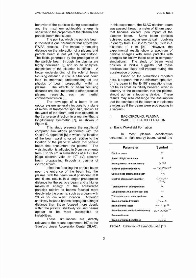
Parameter Symbol
Electron mass m
Speed of light in vacuum c
Beam (plasma) number density nb (n p )
Electron plasma frequency ω p = (n p e2 / ε 0 m)
1/2
Collisionless plasma skin depth c/ ω p
Electron plasma wave number k p = ω p /c =
2 π / λ p Total number of beam particles N
Longitudinal r.m.s. beam spot size σ z
Transverse r.m.s. beam spot size σ r
Beam normalized velocity β = v b /c
Beam Lorentz factor γ = (1 - β )-1/2
Beam betatron oscillation frequency ωb = ω p /(2 γ )1/2
Beam emittance ε
Beam normalized emittance ε N = γε
Table 1. Definition of symbols used [10].
3
8/3/2019 Adrian Down- Particle Beam Waist Location in Plasma Wakefield Acceleration: Introduction and Background
http://slidepdf.com/reader/full/adrian-down-particle-beam-waist-location-in-plasma-wakefield-acceleration 4/12
AMERICAN JOURNAL OF UNDERGRADUATE RESEARCH VOL. 5, NO. 4
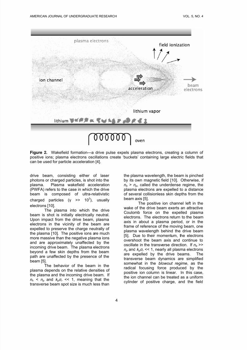
Figure 2. Wakefield formation—a drive pulse expels plasma electrons, creating a column of positive ions; plasma electrons oscillations create ‘buckets’ containing large electric fields thatcan be used for particle acceleration [4].
drive beam, consisting either of laser photons or charged particles, is shot into the
plasma. Plasma wakefield acceleration(PWFA) refers to the case in which the drivebeam is composed of ultra-relativistic
charged particles (γ >> 103), usually
electrons [10].The plasma into which the drive
beam is shot is initially electrically neutral.Upon impact from the drive beam, plasmaelectrons in the vicinity of the beam areexpelled to preserve the charge neutrally of the plasma [10]. The positive ions are muchmore massive than the negative plasma ionsand are approximately unaffected by theincoming drive beam. The plasma electronsbeyond a few skin depths from the beampath are unaffected by the presence of thebeam [5].
The behavior of the beam in theplasma depends on the relative densities of the plasma and the incoming drive beam. If nb < n p and k pσ r << 1, meaning that thetransverse beam spot size is much less than
the plasma wavelength, the beam is pinchedby its own magnetic field [10]. Otherwise, if
nb > n p, called the underdense regime, theplasma electrons are expelled to a distanceof several collisionless skin depths from thebeam axis [5].
The positive ion channel left in thewake of the drive beam exerts an attractiveCoulomb force on the expelled plasmaelectrons. The electrons return to the beamaxis in about a plasma period, or in theframe of reference of the moving beam, oneplasma wavelength behind the drive beam[5]. Due to their momentum, the electronsovershoot the beam axis and continue to
oscillate in the transverse direction. If nb >> n p and k pσ r << 1, nearly all plasma electronsare expelled by the drive beams. Thetransverse beam dynamics are simplifiedsomewhat in the blowout regime, as theradical focusing force produced by thepositive ion column is linear. In this case,the ion channel can be treated as a uniformcylinder of positive charge, and the field
4
8/3/2019 Adrian Down- Particle Beam Waist Location in Plasma Wakefield Acceleration: Introduction and Background
http://slidepdf.com/reader/full/adrian-down-particle-beam-waist-location-in-plasma-wakefield-acceleration 5/12
AMERICAN JOURNAL OF UNDERGRADUATE RESEARCH VOL. 5, NO. 4
within the ion channel can be obtained fromGauss’s law,
r en
E p
r
02
1
ε −= (1)
As the particle beam propagates forward,those oscillating electrons set up a wakefield
consisting of a series of regions of positivecharge, known as buckets, each followed bya dense region of negative charge, asshown in Figure 2. High electric fields candevelop in the region with the positive ionchannel at the rear of each bucketimmediately preceding the region of densenegative charge.
Linear theory predicts that the peakaccelerating field that can be obtained usingthe PWFA method is [10],
2
10
6.0
104) / (240)( ⎟⎟
⎠
⎞⎜⎜
⎝
⎛ ⎟⎟
⎠
⎞⎜⎜
⎝
⎛
×=
z
linear
mm N m MeV E e
σ
.
(2)
Although the underdense regime, nb > n p, isdesirable for particle acceleration, linear theory is no longer valid in this regime. Dueto nonlinearities, the underdense regimemust be studied with particle-in-cell (PIC)
computer simulations. One important linear
theory result, namely that ,
appears to remain valid when theunderdense plasma condition is satisfied[10].
2)()(−∝ z E e σ
Acceleration gradients achieved in
the underdense regime can be greater thanthose predicted by linear theory. As shorter drive beam bunch lengths become possible,acceleration gradients of more than 40GeV/m can be realized [10]. In comparison,the SLAC accelerates particles toapproximately 40 GeV in energy over adistance of about 3.2 km.
Achieving high energies with plasmaaccelerators relies on the ability to injectcharged particles into the region of maximum accelerating gradient at the rear of the first bucket. A pulse, called the
witness beam, is launched behind the drivebeam. The timing is such that the witnessbeam experiences the maximumaccelerating gradient once the wakefield isformed by the drive beam. As the drivebeam propagates through the plasma, theparticles in the witness beam are influencedby the accelerating field and gain energy.
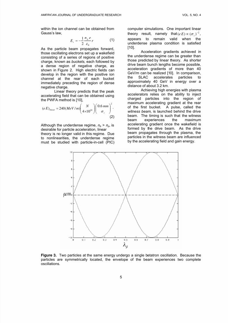
Figure 3. Two particles at the same energy undergo a single betatron oscillation. Because theparticles are symmetrically located, the envelope of the beam experiences two completeoscillations.
5
8/3/2019 Adrian Down- Particle Beam Waist Location in Plasma Wakefield Acceleration: Introduction and Background
http://slidepdf.com/reader/full/adrian-down-particle-beam-waist-location-in-plasma-wakefield-acceleration 6/12
AMERICAN JOURNAL OF UNDERGRADUATE RESEARCH VOL. 5, NO. 4
Because the drive beam is ultra-relativistic, the witness beam must also beultra-relativistic before injection. Thewitness beam travels at nearly the speed of light, and so most energy gained fromacceleration is due to change in momentum
rather than a change in speed. Thus thewitness beam does not outrun the drivepulse as acceleration proceeds. In effect,the plasma acts as a transformer: theenergy of the drive beam is transferred tothe plasma in the formation of the wake,which in turn transfers energy to the witnessbeam.
b. Betatron Oscillation
The focusing force exerted by theion channel can cause the electrons of thedrive beam to oscillate about the axis of the
beam. In the blowout regime, the focusingforce exerted by the ion channel given byequation (1) can be recast in terms of theplasma wave number [11],
( ) r k cmr en
E eF p
p
r r
22
0
2
2
1
2
1−=−==
ε
(3)
The relativistic equation of motion for asingle beam electron is thus,
)( r r
r vmdt
d
dt
dpF γ == (4)
Because the beam is ultra-relativistic, therelation z = ct can be used to rephrase (4) interms of the longitudinal location z,
( )( )( )
r k cmc zd
md p
c zd
r d
22 / )(
2
1
/ −=
γ
or
0)(2
1 2 =+⎟ ⎠
⎞⎜⎝
⎛ r k
dz
dr
dz
d pγ (5)
Equation (5) can be written as the equationof motion for a simple harmonic oscillator
with the definition2 ,2 / 1)2( / γ β pk k =
2 The normalized emittance εN whichappears in (6) is discussed in the later section “Phase space analysis of beamoptics.”
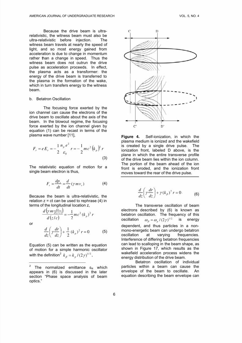
Figure 4. Self-ionization, in which theplasma medium is ionized and the wakefieldis created by a single drive pulse. Theionization front, labeled D above, is theplane in which the entire transverse profileof the drive beam lies within the ion column.The portion of the beam ahead of the ionfront is eroded, and the ionization frontmoves toward the rear of the drive pulse.
0)(2 =+⎟
⎠
⎞⎜⎝
⎛ r k
dz
dr
dz
d β γ γ . (6)
The transverse oscillation of beamelectrons described by (6) is known asbetatron oscillation. The frequency of thisoscillation is energy
dependent, and thus particles in a non-mono-energetic beam can undergo betatronoscillation at varying frequencies.
Interference of differing betatron frequenciescan lead to scalloping in the beam shape, asshown in Figure 17, which results as thewakefield acceleration process widens theenergy distribution of the drive beam.
2 / 1)2( / γ ω ω β p=
Betatron oscillation of individualparticles within a beam can cause theenvelope of the beam to oscillate. Anequation describing the beam envelope can
6
8/3/2019 Adrian Down- Particle Beam Waist Location in Plasma Wakefield Acceleration: Introduction and Background
http://slidepdf.com/reader/full/adrian-down-particle-beam-waist-location-in-plasma-wakefield-acceleration 7/12
AMERICAN JOURNAL OF UNDERGRADUATE RESEARCH VOL. 5, NO. 4
be obtained by summing the oscillations of all individual electrons. The result is [10],
( ) ( )
( )0)()(
42
2
2'' =⎥⎦
⎤⎢⎣
⎡−+ zk z r
r
N
r σ σ γ
ε σ β
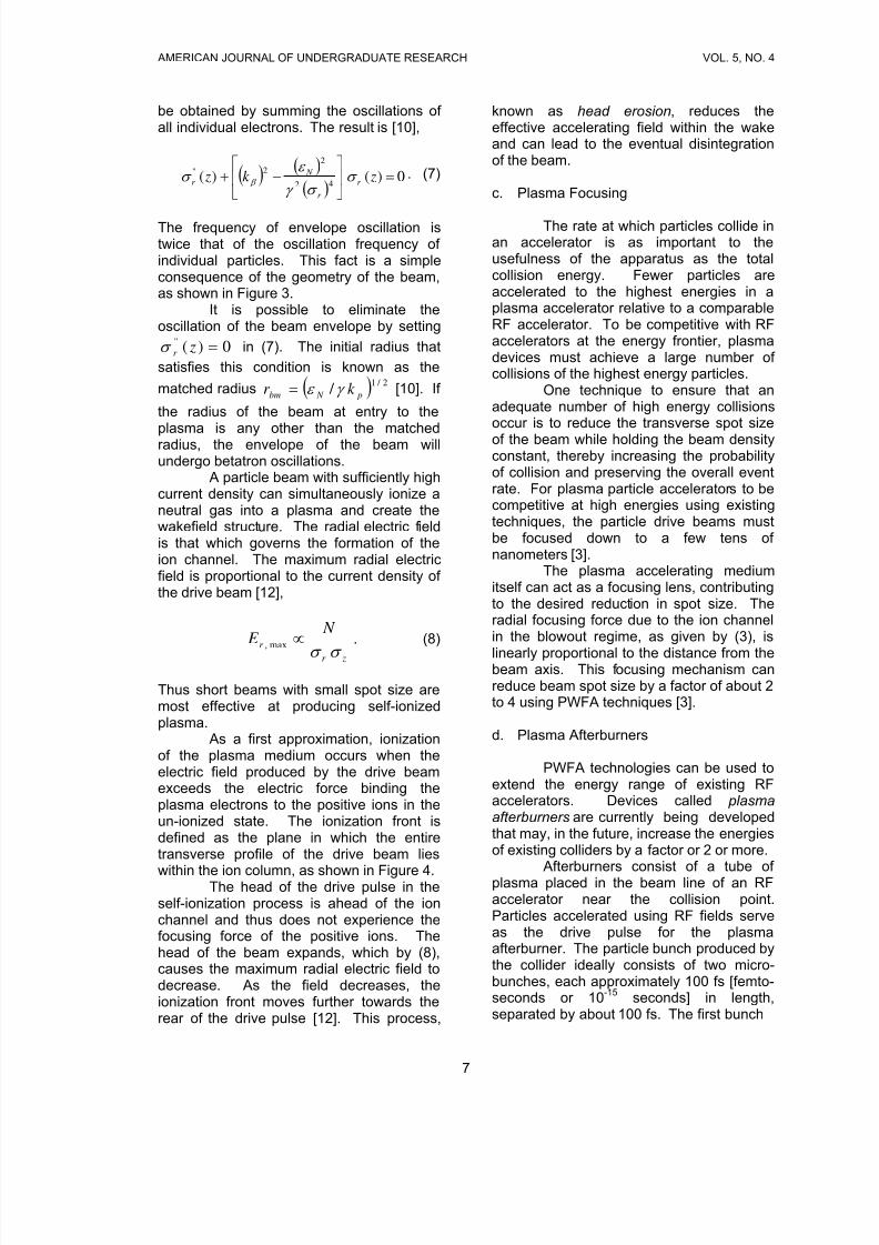
. (7)
The frequency of envelope oscillation istwice that of the oscillation frequency of individual particles. This fact is a simpleconsequence of the geometry of the beam,as shown in Figure 3.
It is possible to eliminate theoscillation of the beam envelope by setting
in (7). The initial radius that
satisfies this condition is known as the
matched radius [10]. If
the radius of the beam at entry to theplasma is any other than the matchedradius, the envelope of the beam willundergo betatron oscillations.
0)('' = zr σ
( 2 / 1 /
p N bm k r γ ε = )
A particle beam with sufficiently highcurrent density can simultaneously ionize aneutral gas into a plasma and create thewakefield structure. The radial electric fieldis that which governs the formation of theion channel. The maximum radial electricfield is proportional to the current density of the drive beam [12],
zr
r
N E
σ σ
∝max,. (8)
Thus short beams with small spot size aremost effective at producing self-ionizedplasma.
As a first approximation, ionizationof the plasma medium occurs when theelectric field produced by the drive beamexceeds the electric force binding theplasma electrons to the positive ions in theun-ionized state. The ionization front isdefined as the plane in which the entiretransverse profile of the drive beam lies
within the ion column, as shown in Figure 4.The head of the drive pulse in the
self-ionization process is ahead of the ionchannel and thus does not experience thefocusing force of the positive ions. Thehead of the beam expands, which by (8),causes the maximum radial electric field todecrease. As the field decreases, theionization front moves further towards therear of the drive pulse [12]. This process,
known as head erosion, reduces theeffective accelerating field within the wakeand can lead to the eventual disintegrationof the beam.
c. Plasma Focusing
The rate at which particles collide inan accelerator is as important to theusefulness of the apparatus as the totalcollision energy. Fewer particles areaccelerated to the highest energies in aplasma accelerator relative to a comparableRF accelerator. To be competitive with RFaccelerators at the energy frontier, plasmadevices must achieve a large number of collisions of the highest energy particles.
One technique to ensure that anadequate number of high energy collisionsoccur is to reduce the transverse spot size
of the beam while holding the beam densityconstant, thereby increasing the probabilityof collision and preserving the overall eventrate. For plasma particle accelerators to becompetitive at high energies using existingtechniques, the particle drive beams mustbe focused down to a few tens of nanometers [3].
The plasma accelerating mediumitself can act as a focusing lens, contributingto the desired reduction in spot size. Theradial focusing force due to the ion channelin the blowout regime, as given by (3), is
linearly proportional to the distance from thebeam axis. This focusing mechanism canreduce beam spot size by a factor of about 2to 4 using PWFA techniques [3].
d. Plasma Afterburners
PWFA technologies can be used toextend the energy range of existing RFaccelerators. Devices called plasmaafterburners are currently being developedthat may, in the future, increase the energiesof existing colliders by a factor or 2 or more.
Afterburners consist of a tube of plasma placed in the beam line of an RFaccelerator near the collision point.Particles accelerated using RF fields serveas the drive pulse for the plasmaafterburner. The particle bunch produced bythe collider ideally consists of two micro-bunches, each approximately 100 fs [femto-seconds or 10-15 seconds] in length,separated by about 100 fs. The first bunch
7
8/3/2019 Adrian Down- Particle Beam Waist Location in Plasma Wakefield Acceleration: Introduction and Background
http://slidepdf.com/reader/full/adrian-down-particle-beam-waist-location-in-plasma-wakefield-acceleration 8/12
AMERICAN JOURNAL OF UNDERGRADUATE RESEARCH VOL. 5, NO. 4
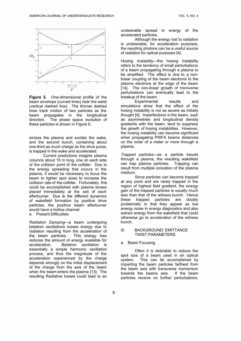
Figure 5. One-dimensional profile of thebeam envelope (curved lines) near the waist(vertical dashed line). The thinner dashedlines track motion of two particles as thebeam propagates in the longitudinal
direction. The phase space evolution of these particles is shown in Figure 6.
ionizes the plasma and excites the wake,and the second bunch, containing aboutone-third as much charge as the drive pulse,is trapped in the wake and accelerated.
Current predictions imagine plasmacolumns about 10 m long, one on each sideof the collision point of the collider. Due tothe energy spreading that occurs in theplasma, it would be necessary to focus the
beam to tighter spot sizes to increase thecollision rate of the collider. Fortunately, thiscould be accomplished with plasma lensesplaced immediately at the exit of eachafterburner. Due to the different dynamicsof wakefield formation by positive driveparticles, the positron beam afterburner would have a hollow channel.e. Present Difficulties
Radiation Damping —a beam undergoingbetatron oscillations looses energy due toradiation resulting from the acceleration of the beam particles. This energy loss
reduces the amount of energy available for acceleration. Betatron oscillation isessentially a simple harmonic oscillationprocess, and thus the magnitude of theacceleration experienced by the chargedepends strongly on the initial displacementof the charge from the axis of the beamwhen the beam enters the plasma [13]. Theresulting Radiative losses could lead to an
undesirable spread in energy of theaccelerated particles.
Although the energy lost to radiationis undesirable, for acceleration purposes,the resulting photons can be a useful sourceof radiation for optical purposes [4].
Hosing Instability —the hosing instabilityrefers to the tendency of small perturbationsof a beam propagating through a plasma tobe amplified. The effect is due to a non-linear coupling of the beam electrons to theplasma electrons at the edge of the beam[14]. The non-linear growth of transverseperturbations can eventually lead to thebreakup of the beam.
Experimental results andsimulations show that the effect of thehosing instability is not as severe as initiallythought [4]. Imperfections in the beam, such
as asymmetries and longitudinal densitygradients with the beam, tend to suppressthe growth of hosing instabilities. However,the hosing instability can become significantwhen propagating PWFA beams distanceson the order of a meter or more through aplasma.
Trapped particles—as a particle travelsthrough a plasma, the resulting wakefieldcan trap plasma particles. Trapping canresult from multiple ionization of the plasmamedium.
Since particles can become trappedat any point and are rarely trapped in theregion of highest field gradient, the energygain of the trapped particles is usually muchless than that of the witness bunch. Hencethese trapped particles are doublyproblematic in that they appear as lowenergy noise in energy diagnostics and alsoextract energy from the wakefield that couldotherwise go to acceleration of the witnessbunch.
III. BACKGROUND: EMITTANCETWIST PARAMETERS
a. Beam Focusing
Often it is desirable to reduce thespot size of a beam used in an opticalsystem. This can be accomplished byimparting the beam particles farthest fromthe beam axis with transverse momentumtowards the beams axis. If the beamparticles receive no further perturbations,
8
8/3/2019 Adrian Down- Particle Beam Waist Location in Plasma Wakefield Acceleration: Introduction and Background
http://slidepdf.com/reader/full/adrian-down-particle-beam-waist-location-in-plasma-wakefield-acceleration 9/12
AMERICAN JOURNAL OF UNDERGRADUATE RESEARCH VOL. 5, NO. 4
the beam envelope contracts to minimumspot size. The location of the plane at whichthis minimum occurs is known as the beamwaist . The beam envelope expandssymmetrically on the opposite side of thebeam waist [7], as shown in Figure 5.
In the case that the beam is notazimuthally symmetrical, the waist locationcan vary for differing transverse directions.The beam envelope will evolveindependently in the two planes formed bythe transverse coordinate axes, respectively,and the beam axis.
Consider a single transversedimension of a beam undergoing focusing.Let this arbitrarily-chosen direction be calledy . Beam particles farthest from the beamaxis are given transverse momentum toreduce the spot size of the beam. Henceparticles at large –y receive momentum in
the positive direction and particles at large+y receive momentum in the negativetransverse direction.
The behavior of a representativeparticle is shown in Figure 5, labeled ‘1’.Assuming that no forces act on the beamparticles, the transverse momentum of particle 1 carries it through the beam axis.The particle continues past the beam axis.Similar behavior for other beam particlesresults in expansion of the beam envelopeas the beam propagates past the plane of the waist.
Because of focusing imperfections,some beam particles off the beam axisreceive no transverse momentum. Theseparticles limit the minimum spot size of thebeam. A representative particle is labeledas ‘2’ in Figure 5. As the beam propagates,such particles maintain constant transversepositions.
b. Phase Space Analysis
It is useful to analyze the focusing of such a beam in phase space. The phase
space description leads to the definition of emittance and the Twist parameters. Theemittance is an important characterization of the angular spread of the beam, and theTwist parameters can be used to specify thewaist location of the beam.
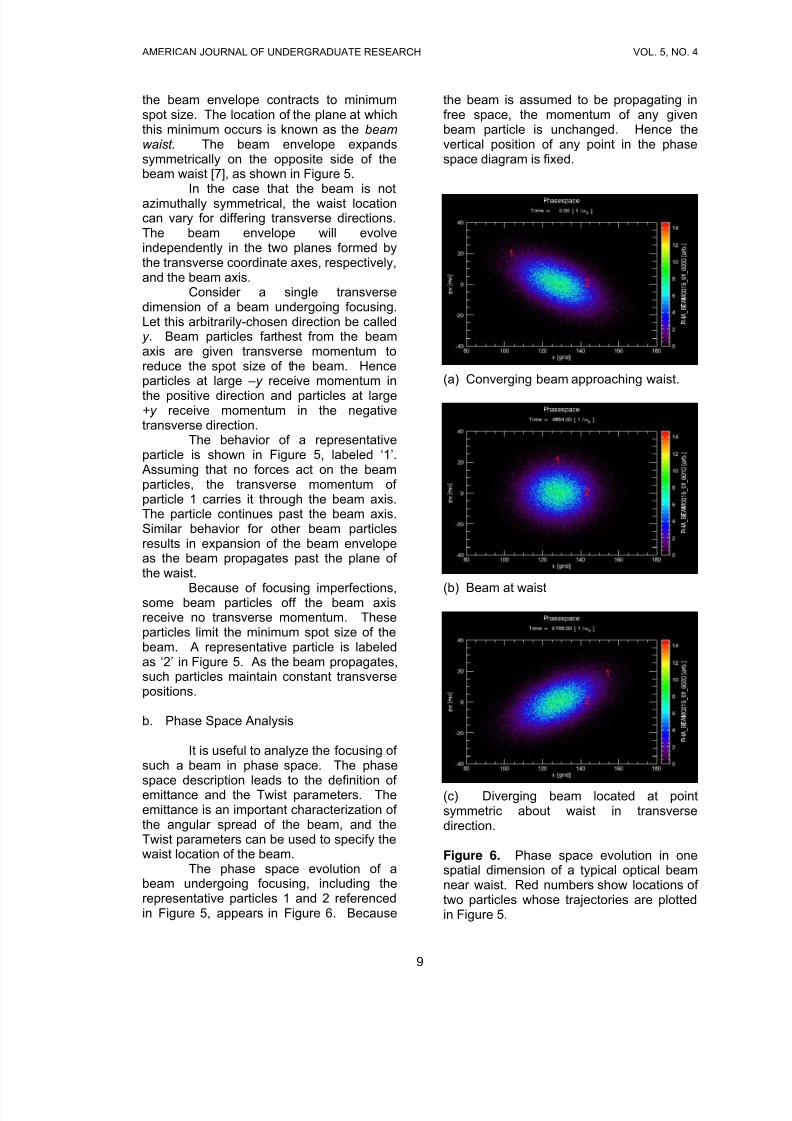
The phase space evolution of abeam undergoing focusing, including therepresentative particles 1 and 2 referencedin Figure 5, appears in Figure 6. Because
the beam is assumed to be propagating infree space, the momentum of any givenbeam particle is unchanged. Hence thevertical position of any point in the phasespace diagram is fixed.
(a) Converging beam approaching waist.
(b) Beam at waist
(c) Diverging beam located at pointsymmetric about waist in transversedirection.
Figure 6. Phase space evolution in onespatial dimension of a typical optical beamnear waist. Red numbers show locations of two particles whose trajectories are plottedin Figure 5.
9
8/3/2019 Adrian Down- Particle Beam Waist Location in Plasma Wakefield Acceleration: Introduction and Background
http://slidepdf.com/reader/full/adrian-down-particle-beam-waist-location-in-plasma-wakefield-acceleration 10/12
AMERICAN JOURNAL OF UNDERGRADUATE RESEARCH VOL. 5, NO. 4
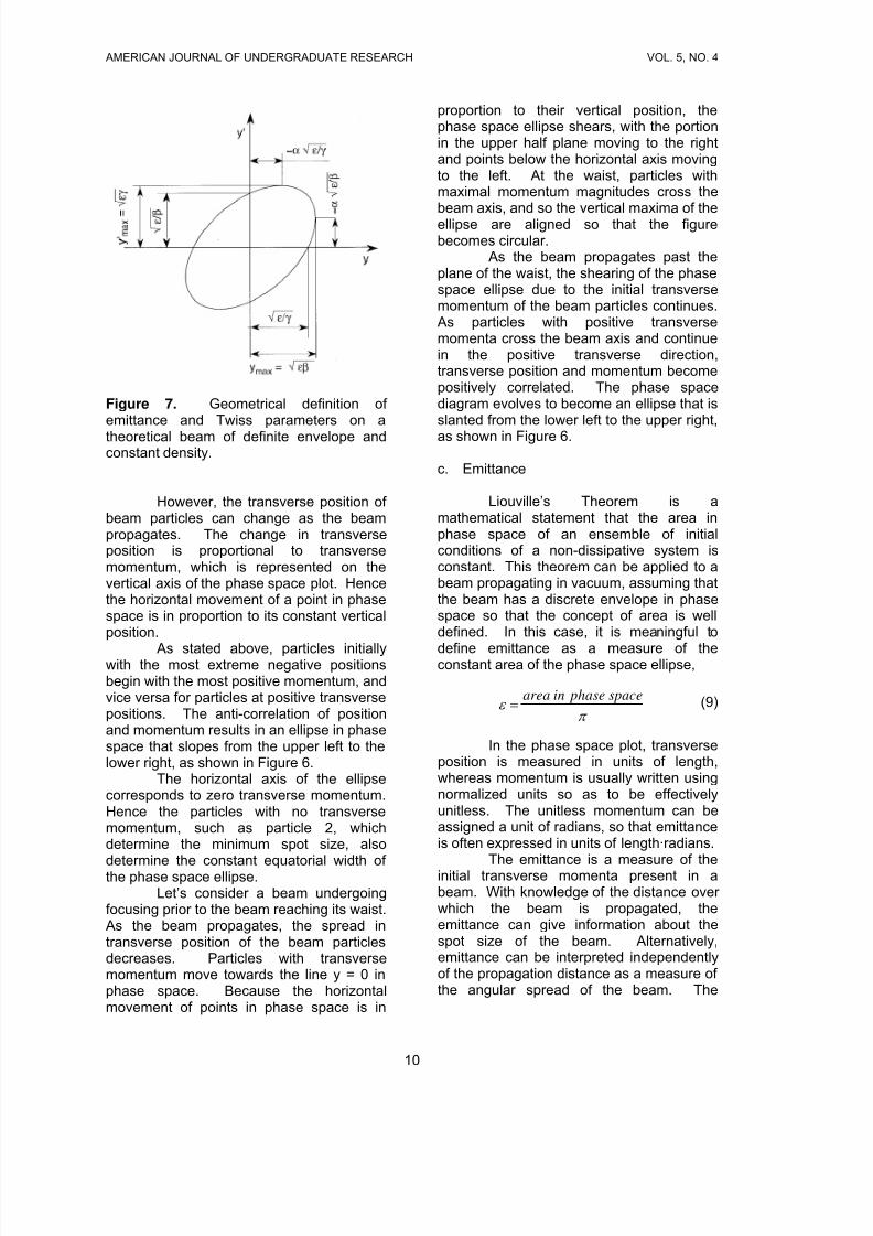
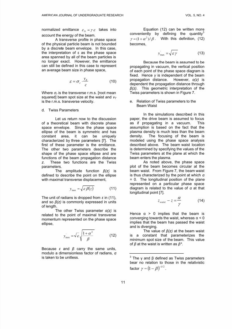
Figure 7. Geometrical definition of emittance and Twiss parameters on a
theoretical beam of definite envelope andconstant density.
However, the transverse position of beam particles can change as the beampropagates. The change in transverseposition is proportional to transversemomentum, which is represented on thevertical axis of the phase space plot. Hencethe horizontal movement of a point in phasespace is in proportion to its constant verticalposition.
As stated above, particles initiallywith the most extreme negative positionsbegin with the most positive momentum, andvice versa for particles at positive transversepositions. The anti-correlation of positionand momentum results in an ellipse in phasespace that slopes from the upper left to thelower right, as shown in Figure 6.
The horizontal axis of the ellipsecorresponds to zero transverse momentum.Hence the particles with no transversemomentum, such as particle 2, whichdetermine the minimum spot size, also
determine the constant equatorial width of the phase space ellipse.Let’s consider a beam undergoing
focusing prior to the beam reaching its waist.As the beam propagates, the spread intransverse position of the beam particlesdecreases. Particles with transversemomentum move towards the line y = 0 inphase space. Because the horizontalmovement of points in phase space is in
proportion to their vertical position, thephase space ellipse shears, with the portionin the upper half plane moving to the rightand points below the horizontal axis movingto the left. At the waist, particles withmaximal momentum magnitudes cross thebeam axis, and so the vertical maxima of theellipse are aligned so that the figurebecomes circular.
As the beam propagates past theplane of the waist, the shearing of the phasespace ellipse due to the initial transversemomentum of the beam particles continues.As particles with positive transversemomenta cross the beam axis and continuein the positive transverse direction,transverse position and momentum becomepositively correlated. The phase spacediagram evolves to become an ellipse that isslanted from the lower left to the upper right,
as shown in Figure 6.
c. Emittance
Liouville’s Theorem is amathematical statement that the area inphase space of an ensemble of initialconditions of a non-dissipative system isconstant. This theorem can be applied to abeam propagating in vacuum, assuming thatthe beam has a discrete envelope in phasespace so that the concept of area is welldefined. In this case, it is meaningful to
define emittance as a measure of theconstant area of the phase space ellipse,
π ε
space phaseinarea= (9)
In the phase space plot, transverseposition is measured in units of length,whereas momentum is usually written usingnormalized units so as to be effectivelyunitless. The unitless momentum can beassigned a unit of radians, so that emittanceis often expressed in units of length·radians.
The emittance is a measure of theinitial transverse momenta present in abeam. With knowledge of the distance over which the beam is propagated, theemittance can give information about thespot size of the beam. Alternatively,emittance can be interpreted independentlyof the propagation distance as a measure of the angular spread of the beam. The
10
8/3/2019 Adrian Down- Particle Beam Waist Location in Plasma Wakefield Acceleration: Introduction and Background
http://slidepdf.com/reader/full/adrian-down-particle-beam-waist-location-in-plasma-wakefield-acceleration 11/12
AMERICAN JOURNAL OF UNDERGRADUATE RESEARCH VOL. 5, NO. 4
normalized emittance ε γ ε = N takes into
account the energy of the beam.A transverse profile in phase space
of the physical particle beam is not boundedby a discrete beam envelope. In this case,the interpretation of ε as the phase space
area spanned by all of the beam particles isno longer exact. However, the emittancecan still be defined in this case to representan average beam size in phase space,
c
vT r ⋅=σ ε (10)
Where σ r is the transverse r.m.s. [root meansquared] beam spot size at the waist and v T is the r.m.s. transverse velocity.
d. Twiss Parameters
Let us return now to the discussionof a theoretical beam with discrete phasespace envelope. Since the phase spaceellipse of the beam is symmetric and hasconstant area, it can be uniquelycharacterized by three parameters [7]. Thefirst of these parameter is the emittance.The other two parameters describe theshape of the phase space ellipse and arefunctions of the beam propagation distancez . These two functions are the Twissparameters.
The amplitude function β
(z) isdefined to describe the point on the ellipsewith maximal transverse displacement,
( ) z y β ε =max
(11)
The unit of radians is dropped from ε in (11),and so β(z) is commonly expressed in unitsof length.
The other Twiss parameter α (z) isrelated to the point of maximal transversemomentum represented on the phase spaceellipse,
β
α ε
2'
max
1+= y (12)
Because ε and β carry the same units,modulo a dimensionless factor of radians, α is taken to be unitless.
Equation (12) can be written mor e conveniently by defining the quantity3
. With this definition, (12)
becomes,
β α γ / )1(2+=
γ ε ='
max y (13)
Because the beam is assumed to bepropagating in vacuum, the vertical positionof each point of the phase space diagram isfixed. Hence γ is independent of the beampropagation distance. However, α (z) isdependent the propagation distance through β(z). This geometric interpretation of theTwiss parameters is shown in Figure 7.
e. Relation of Twiss parameters to theBeam Waist
In the simulations described in thispaper, the drive beam is assumed to focusas if propagating in a vacuum. Thisassumption is based on the fact that theplasma density is much less than the beamdensity. The focusing of the beam ismodeled using the phase space analysisdescribed above. The beam waist locationis determined by specifying the values of theTwiss parameters at the plane at which thebeam enters the plasma.
As noted above, the phase spaceplot of the beam becomes circular at thebeam waist. From Figure 7, the beam waistis thus characterized by the point at which α = 0. The longitudinal position of the planerepresented on a particular phase spacediagram is related to the value of α at thatlongitudinal point [7].
γ
α =− z zwaist (14)
Hence α > 0 implies that the beam isconverging towards the waist, whereas α < 0implies that the beam has passed the waistand is diverging.
The value of β(z) at the beam waistis a constant that parameterizes theminimum spot size of the beam. This valueof β at the waist is written as β* .
3 The γ and β defined as Twiss parametersbear no relation to those in the relativistic
factor ( ) 2 / 11
−−= β γ .
11
8/3/2019 Adrian Down- Particle Beam Waist Location in Plasma Wakefield Acceleration: Introduction and Background
http://slidepdf.com/reader/full/adrian-down-particle-beam-waist-location-in-plasma-wakefield-acceleration 12/12
AMERICAN JOURNAL OF UNDERGRADUATE RESEARCH VOL. 5, NO. 4
ACKNOWLEDGEMENTS
I would like to thank Professor W. B. Moriand Miaomiao Zhou for their guidance inpreparing this research. I would also like tothank Françcoise Quéval, the University of California, Los Angeles, and the National
Science Foundation Research Experiencesfor Undergraduates program for their generosity and support.
Editorial Note: The research outlined abovewill be continued in the next issue (June2007), where Methods, Data and Discussionsections will be reported.
REFERENCES
1. John M. Dawson, “Plasma ParticleAccelerators,” Scientific American, vol.
260 (1989) 54-61.2. Chandrasekhar Joshi, “Plasma
Accelerators,” Scientific American, vol.294, no. 2 (2006) 41-47.
3. Chandrasekhar Joshi and ThomasKatsouleas, “Particle Accelerators at theEnergy Frontier and on Tabletops,”Physics Today (June 2003) 47-53.
4. F.J. Decker, et al., “Multi-GeV PlasmaWakefield Acceleration Experiments,” E-167 Proposal (2005).
5. W. Lu, C. Huang, M. Zhou, W.B. Mori,and T. Katsouleas, “Nonlinear Theory
for Relativistic Plasma Wakefields in theBlowout Regime,” Physical Review Letters, vol. 96 (2006) 165002.
6. K. Fournier, “Recent Progress on Laser-Driven X-Ray Sources” [presentation tothe Department of ElectricalEngineering, UCLA] 2006.
7. K.G. Steffen, High Energy Beam Optics (Interscience-Wiley, New York, 1965).
8. C. Huang, V.K. Decyk, C. Ren, M. Zhou,W. Lu, W.B. Mori, J.H. Cooley, T. M.Antonsen, and T. Katsouleas, Journal of Computational Physics (2006).
9. M. Shou, Preliminary Data from theE167 collaboration (personalcommunication).
10. C. Joshi, et al., Physics of Plasmas, vol.9 (2002) 1845.
11. A.A. Geraci and D.H. Whittum, Physicsof Plasmas, vol. 7 (2000) 3431.
12. Miaomiao Zhou, Development and applications of the ionization: package inQuickPIC - a novel quasi-static PIC
code for PWFA study . Thesis (M.S.)UCLA, 2005.
13. P. Michel, E. Esarey, C. Schroeder, B.Shadwick, W. Leemans, “High EfficiencyElectron Injection for PlasmaAccelerators Using Higher-order laser Modes,” Physics of Plasmas (in press).
14. D.H. Whittum, W.M. Sharp, S.S. Yu, M.Lampe, and G. Joyce, Physical Review Letters, vol. 67 (1991) 991.
UNIVERSITY OF
CALIFORNIA
BERKELEY
PHYSICS AT BERKELEY has long been inthe forefront of discovery and achievement.In 1931, Ernest O. Lawrence invented thecyclotron at Berkeley, ushering in the era of high-energy physics and a tradition of achievement that continues today. Seven of Berkeley’s nineteen Nobel Prizes wereawarded to Berkeley physicists. The most
recent National Research Councilnationwide rankings identify the Departmentas one of the best in the nation. In the last50 years, Berkeley physicists have mademany of the significant discoveries thatsupport today’s science. These discoveriesextend from fundamental properties of elementary particles to spin echoes – thebasis of magnetic resonance imaging – tocutting-edge breakthroughs for building anaccurate model of how the universe tookshape following the monster explosioncommonly known as the Big Bang. Today,faculty members are leading the way to inscientific research and discovery in waysthat may challenge the fundamental laws of
physics particularly in the areas of gravitation, matter, and energy. At thesame time, undergraduate and graduateteaching—through formal courses andresearch activity—is an integral part of thefaculty’s commitment to the development of tomorrow’s scientists. In their pursuit of original research, physics faculty memberscollaborate with postdoctoral fellows, PhDgraduate students, undergraduate students,and visiting scholars.
12