Embed Size (px)
Citation preview
ADR2100
ANALOG/DIGITALRS232/RS485INTERFACE
USER MANUAL
V 3.0
Caution: The ADR2100 is a static sensitive device. Observe proper proceduresfor handling static sensitive devices.
ONTRAK CONTROL SYSTEMS INC.764 Notre Dame Avenue
Unit # 1Sudbury Ontario
CANADA P3A 2T2(705) 671-2652 ( VOICE )
(705) 671-6127 ( FAX )www.ontrak.net ( WEB )
Ontrak Control Systems Inc. reserves the right to change product specifications to improve the
product.
Although every attempt has been made to insure accuracy of information contained in this manual,
Ontrak Control Systems Inc. assumes no liability for inadvertent errors.
Warranty: This ADR2100 is warranted from defects in workmanship and materials for a period of
90 days. Liability for defects is limited to the purchase price of the product. This warranty shall not
apply to defects resulting from improper modifications or use outside published specifications.
Hyperterminal and Windows are trademarks of Microsoft Corporation.
APPLE , MACINTOSH and MAC are trademarks of Apple Computer Inc.
PC, XT, AT, PS/2 are trademarks of International Business Machines Inc.
COPYRIGHT 1998 ONTRAK CONTROL SYSTEMS INC.

TABLE OF CONTENTS
READ ME FIRST 3
1. Communication options.
a) The ADR2100 RS232 Interface. 4
b) The ADR2100 RS485 Interface 5
2. Powering the ADR2100 5
3. ADR2100 Commands 6
a) Analog Input Commands 7
b) Digital Port Commands 7
c) PWM Output Commands 8
d) Event Counter Commands 9
e) Stepper Motor Indexer Commands 9
f) Interrupt Commands 10
g) ID Command 11
4. Using BASIC with ADR Products 12
5. Using TURBO C with ADR Products 13
6. Daisy Chain Options for the ADR2100 16
7. Interfacing to the ADR2100 ( basic examples ) 17
a) Reading Potentiometer Position 17
b) Connecting Switches to Digital Ports 18
c) Connecting LED'S to Digital Ports 19
d) Driving Solid-State Relays 20
e) Solid-State Temperature Measurement 20
f) Event-Counter Connections 21
g) Using the Stepper Motor Indexer 21
h) Using Interrupt Functions. 23
APPENDIX
A-CONNECTION DIAGRAM 25
B-ELECTRICAL SPECIFICATIONS 26
C-MOUNTING DIMENSIONS 27
ONTRAK CONTROL SYSTEMS INC. 2/27 www.ontrak.net
ONTRAK CONTROL SYSTEMS INC. 3/27 www.ontrak.net
READ ME FIRST
Thank you for purchasing this ADR2100 Serial Data Acquisition Interface. Thereare three steps to using the ADR2100.
1.Connecting your computer or terminal to the ADR2100.
2.Providing power to the ADR2100.
3.Sending commands to the ADR2100.
This manual will provide guidance for completing these steps along with BASIC and TURBO C programming tips. An applications section is also provided to describehow to interface various electronic transducers and other devices to the ADR2100.Additional applications and programming examples are available on our web pageat http://www.ontrak.net/
FEATURES
-4 10-bit analog inputs ( 0 - 5 VDC )-2, 10-bit PWM outputs-2, 16-bit contact or TTL input event counters-32 digital I/O lines individually programmable as input or output-high current digital I/O lines ( sink 20mA/source 20mA )-4, interrupt lines ( TTL )-dual stepper motor indexer function-on-board RS232 to RS485 converter-daisy-chainable up to 10 boards-daisy-chainable power supply-low power requirements ( 5 volts at 30mA Typical )-power-up via standard wall adapter ( optional )-simple yet versatile commands-easy to use with Visual BASIC or TURBO C programs-compatible with ADR2000 interfaces
ONTRAK CONTROL SYSTEMS INC. 4/27 www.ontrak.net
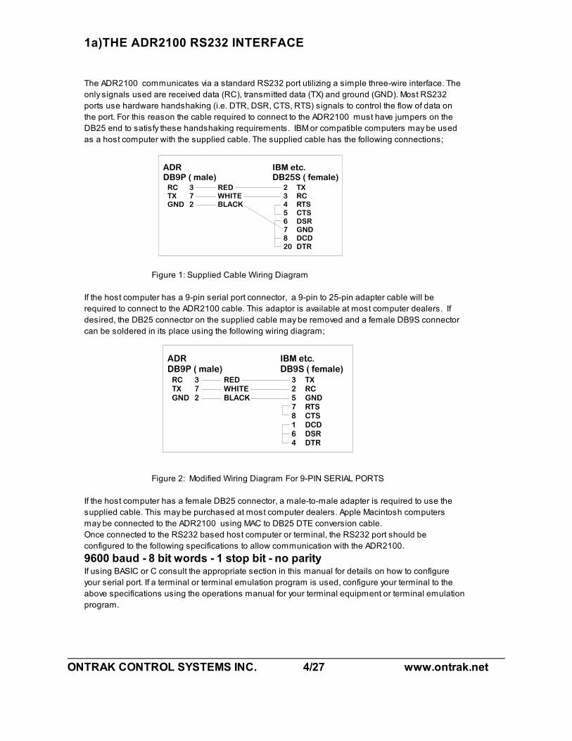
1a)THE ADR2100 RS232 INTERFACE
The ADR2100 communicates via a standard RS232 port utilizing a simple three-wire interface. The
only signals used are received data (RC), transmitted data (TX) and ground (GND). Most RS232
ports use hardware handshaking (i.e. DTR, DSR, CTS, RTS) signals to control the flow of data on
the port. For this reason the cable required to connect to the ADR2100 must have jumpers on the
DB25 end to satisfy these handshaking requirements. IBM or compatible computers may be used
as a host computer with the supplied cable. The supplied cable has the following connections;
Figure 1: Supplied Cable Wiring Diagram
If the host computer has a 9-pin serial port connector, a 9-pin to 25-pin adapter cable will be
required to connect to the ADR2100 cable. This adaptor is available at most computer dealers. If
desired, the DB25 connector on the supplied cable may be removed and a female DB9S connector
can be soldered in its place using the following wiring diagram;
Figure 2: Modified Wiring Diagram For 9-PIN SERIAL PORTS
If the host computer has a female DB25 connector, a male-to-male adapter is required to use the
supplied cable. This may be purchased at most computer dealers. Apple Macintosh computers
may be connected to the ADR2100 using MAC to DB25 DTE conversion cable.
Once connected to the RS232 based host computer or terminal, the RS232 port should be
configured to the following specifications to allow communication with the ADR2100.
9600 baud - 8 bit words - 1 stop bit - no parityIf using BASIC or C consult the appropriate section in this manual for details on how to configure
your serial port. If a terminal or terminal emulation program is used, configure your terminal to the
above specifications using the operations manual for your terminal equipment or terminal emulation
program.
ONTRAK CONTROL SYSTEMS INC. 5/27 www.ontrak.net
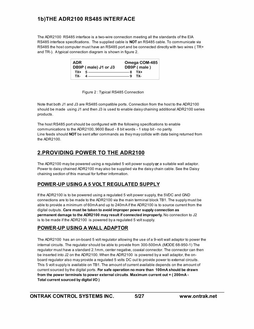
1b)THE ADR2100 RS485 INTERFACE
The ADR2100 RS485 interface is a two-wire connection meeting all the standards of the EIA
RS485 interface specifications. The supplied cable is NOT an RS485 cable. To communicate via
RS485 the host computer must have an RS485 port and be connected directly with two wires ( TR+
and TR-). A typical connection diagram is shown in figure 2.
Figure 2 : Typical RS485 Connection
Note that both J1 and J3 are RS485 compatible ports. Connection from the host to the ADR2100
should be made using J1 and then J3 is used to enable daisy chaining additional ADR2100 series
products.
The host RS485 port should be configured with the following specifications to enable
communications to the ADR2100, 9600 Baud - 8 bit words - 1 stop bit - no parity.
Line feeds should NOT be sent after commands as they may collide with data being returned from
the ADR2100.
2.PROVIDING POWER TO THE ADR2100
The ADR2100 may be powered using a regulated 5 volt power supply or a suitable wall adaptor.
Power to daisy chained ADR2100 may also be supplied via the daisy chain cable. See the Daisy
chaining section of this manual for further information.
POWER-UP USING A 5 VOLT REGULATED SUPPLY
If the ADR2100 is to be powered using a regulated 5 volt power supply, the 5VDC and GND
connections are to be made to the ADR2100 via the main terminal block TB1. The supply must be
able to provide a minimum of 60mA and up to 240mA if the ADR2100 is to source current from the
digital outputs. Care must be taken to avoid improper power supply connection as
permanent damage to the ADR2100 may result if connected improperly. No connection to J2
is to be made if the ADR2100 is powered by a regulated 5 volt supply.
POWER-UP USING A WALL ADAPTOR
The ADR2100 has an on-board 5 volt regulator allowing the use of a 9-volt wall adaptor to power the
internal circuits. The regulator should be able to provide from 300-500mA .(MODE 68-950-1) The
regulator must have a standard 2.1mm, center negative, coaxial connector. The connector can then
be inserted into J2 on the ADR2100. When the ADR2100 is powered by a wall adaptor, the on-
board regulator also may provide a regulated 5 volts DC out to provide power to external circuits.
This 5 volt supply is available on TB1. The amount of current available depends on the amount of
current sourced by the digital ports. For safe operation no more than 100mA should be drawn
from the power terminals to power external circuits. Maximum current out = ( 200mA -
Total current sourced by digital I/O )
ONTRAK CONTROL SYSTEMS INC. 6/27 www.ontrak.net
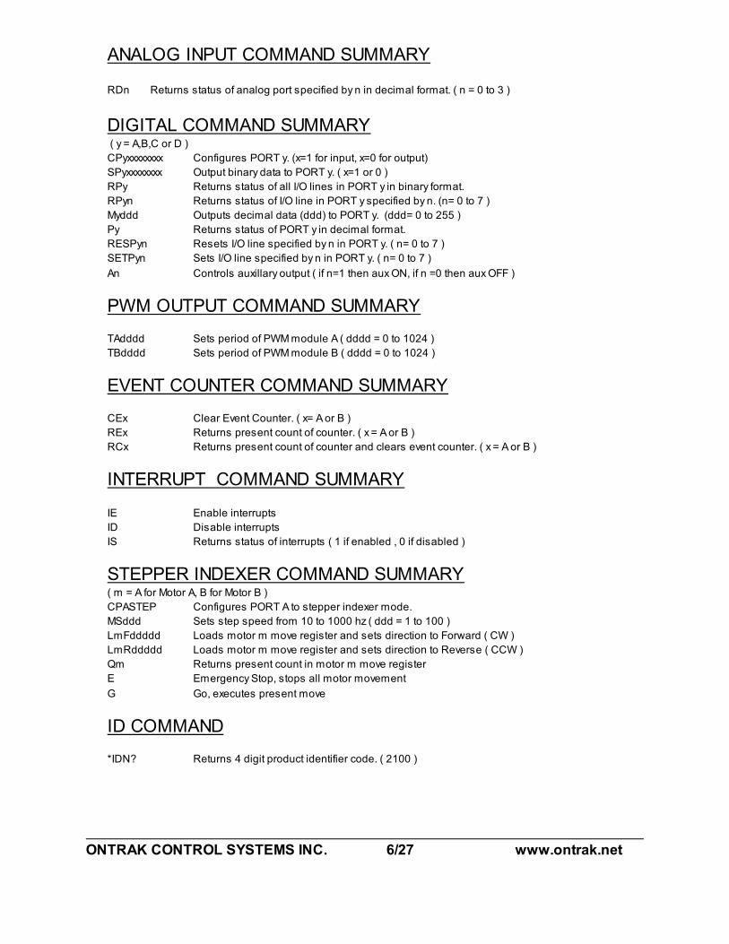
ANALOG INPUT COMMAND SUMMARY
RDn Returns status of analog port specified by n in decimal format. ( n = 0 to 3 )
DIGITAL COMMAND SUMMARY ( y = A,B,C or D )
CPyxxxxxxxx Configures PORT y. (x=1 for input, x=0 for output)
SPyxxxxxxxx Output binary data to PORT y. ( x=1 or 0 )
RPy Returns status of all I/O lines in PORT y in binary format.
RPyn Returns status of I/O line in PORT y specified by n. (n= 0 to 7 )
Myddd Outputs decimal data (ddd) to PORT y. (ddd= 0 to 255 )
Py Returns status of PORT y in decimal format.
RESPyn Resets I/O line specified by n in PORT y. ( n= 0 to 7 )
SETPyn Sets I/O line specified by n in PORT y. ( n= 0 to 7 )
An Controls auxillary output ( if n=1 then aux ON, if n =0 then aux OFF )
PWM OUTPUT COMMAND SUMMARY
TAdddd Sets period of PWM module A ( dddd = 0 to 1024 )
TBdddd Sets period of PWM module B ( dddd = 0 to 1024 )
EVENT COUNTER COMMAND SUMMARY
CEx Clear Event Counter. ( x= A or B )
REx Returns present count of counter. ( x = A or B )
RCx Returns present count of counter and clears event counter. ( x = A or B )
INTERRUPT COMMAND SUMMARY
IE Enable interrupts
ID Disable interrupts
IS Returns status of interrupts ( 1 if enabled , 0 if disabled )
STEPPER INDEXER COMMAND SUMMARY( m = A for Motor A, B for Motor B )
CPASTEP Configures PORT A to stepper indexer mode.
MSddd Sets step speed from 10 to 1000 hz ( ddd = 1 to 100 )
LmFddddd Loads motor m move register and sets direction to Forward ( CW )
LmRddddd Loads motor m move register and sets direction to Reverse ( CCW )
Qm Returns present count in motor m move register
E Emergency Stop, stops all motor movement
G Go, executes present move
ID COMMAND
*IDN? Returns 4 digit product identifier code. ( 2100 )
ONTRAK CONTROL SYSTEMS INC. 7/27 www.ontrak.net
3. ADR2100 COMMANDS
a) ANALOG INPUT COMMAND
There are 4 analog inputs, with a resolution of 10-bits, on the ADR2100 labeled AN0 to AN3. The
analog input range is 0 to 5 VDC.
RDn Returns status of analog port specified by n in decimal format. ( n = 0 to 3 )
(Input voltage range used for conversion 0 to 5VDC)
example; RD0<CR>
0786
To convert to voltage; voltage = ( reading/1023 ) * 5
Ex. AN0 is at (786/1023) * 5 volts= 3.842 volts
b) DIGITAL PORT COMMANDS
There are 4 eight bit digital ports on the ADR2100 labeled PORT A,B,C and D. The individual I/O
lines are labeled Py0-Py7. ( y = A,B,C or D ). There is also one open drain output capable of
sinking 60mA labeled AUX. The following commands allow the user to;
-configure individual bits an input or output
-SET or RESET individual bits
-read individual bits
-read entire port in binary or decimal format
-write to entire port in binary or decimal format.
-turn AUX output on and off
NOTE: PORT A bits 0,1,2 and 3 have built in pull-up resistors active when configured as
input. Care should be taken when using these pins as output, because on power-up, all
digital I/O is configured as input, pulling these pins high.
CPyxxxxxxxx Configures each bit of PORT y . All eight bits must be specified. Order
is MSB-LSB ( x=1 for input, x=0 for output )
example; CPA11110000<CR>
( PA7 ,PA6, PA5, PA4 are configured as inputs and PA3, PA2, PA1, PA0 are
configured as outputs )
SPyxxxxxxxx Outputs binary data to PORT y. All eight bits must be specified.
Order is MSB-LSB. Individual bits configured as input are not
effected by this command. (x=1 or 0 )
example; SPA10101000<CR>
( PA7, PA5, PA3 are set, PA6, PA4, PA2, PA1, PA0 are reset )
RPy Returns status of all I/O lines in PORT y in binary format. Order is MSB-LSB.
Individual lines configured as output will return last data set on the port.
ONTRAK CONTROL SYSTEMS INC. 8/27 www.ontrak.net
example; RPA<CR>
0 1 1 1 0 0 1 0
( PA7, PA3, PA2, PA0 are low, PA6, PA5 ,PA4, PA1 are high )
RPyn Returns status of I/O line in PORT y specified by n.( n=0 to 7 )
example; RPA4<CR>
1
( PA4 is high )
Myddd Outputs decimal data (ddd) to PORT y. Individual lines configured as
input are not effected by this command. (ddd= 000 to 255 )
example; MC255<CR>
( All lines of PORT C are set )
Py Returns status of PORT y in decimal format. Individual lines configured as
output will return last data set on PORT y.
example; PA<CR>
128
( PA7 is high, PA6 thru PA0 are low )
RESPyn Resets I/O line specified by n in PORT y. This command has no effect on I/O
lines configured as input. ( n=0 to 7 )
example; RESPD4<CR>
( PD4 is reset )
SETPyn Sets I/O line specified by n in PORT y. This command has no effect on I/O
lines configured as input. ( n=0 to 7)
example; SETPA3<CR>
( PA3 is set )
An Controls open drain auxiliary output ( n=1 for ON, n=0 for OFF)
example; A1<CR>
AUX open drain output is turned on
example; A0<CR>
AUX open drain output is OFF ( high impedance )
c) PWM OUTPUT COMMANDS
There are two 10-bit PWM outputs on the ADR2100 labeled PWMA and PWMB. The output
frequency is fixed at 9.76KHz and the duty cycle is variable from 0 to 100%. The commands used
to set the duty cycle are;
TAdddd Sets the period of PWMA output. ( dddd=0000 to 1024 )
( 0000 = 0% 1024 = 100% )
ONTRAK CONTROL SYSTEMS INC. 9/27 www.ontrak.net
example; TA512<CR>
period is set to 512/1024 = 50%
TBdddd Sets the period of PWMB output. ( dddd=0000 to 1024 )
( 0000 = 0% 1024 = 100% )
example; TB232<CR>
period is set to 232/1024 = 22.65%
d) EVENT COUNTER COMMANDS
The ADR2100 is equipped with two 16-bit event counters ( ECA and ECB ) that accept TTL or
contact input. There are three commands available to read, and clear the event counters. If the
maximum count of 65535 is reached the counter will rollover to 00000 .
REy Returns decimal value of event counter (y = A or B )
example; REA<CR>
00456
( Present count in counter A is 456.)
CEy Clears event counter ( y = A or B )
example; CEB<CR>
( Event counter B is cleared to 00000 )
RCy Reads and clears event counter (y = A or B )
example; RCA<CR>
12034
( ECA count is returned ( 12034 ) and counter is reset to 00000. )
e) STEPPER INDEXER COMMANDS
The ADR2100 has a dual stepper indexer that will provide step and direction information to two
stepper motor translator circuits. The indexer uses PORT A ( when configured to indexer mode ) to
provide drive signals and read limit switches. See section 7g) of this manual for further information.
CPASTEP Configures PORT A to indexer mode and assigns the following functions
to PORT A.
PA0 Motor A Reverse ( CCW) limit (INPUT)
PA1 Motor A Forward (CW) limit (INPUT)
PA2 Motor B Reverse ( CCW) limit (INPUT)
PA3 Motor B Forward ( CW ) limit (INPUT)
PA4 Motor A STEP output (OUTPUT)
PA5 Motor A DIR output (OUTPUT)
PA6 Motor B STEP output (OUTPUT)
PA7 Motor B DIR output (OUTPUT)
ONTRAK CONTROL SYSTEMS INC. 10/27 www.ontrak.net
MSddd Sets speed of moves for both motors from 10 to 1000 steps/second.
( ddd= 1 to 100 )
Actual speed = ddd*10
example; MS23<CR>
Sets speed of moves to 230 steps per second
LmFddddd Loads move register for motor m ( A or B ) with move information and sets
direction to forward.
ddddd = 0 to 49999
example; LAF10000<CR>
Loads motor A move register with 10000 and sets direction for motor A to forward (
CW )
LmRddddd Loads move register for motor m ( A or B ) with move information and sets
direction to reverse.
ddddd = 0 to 49999
example; LBF4400<CR>
Loads motor B move register with 4400 and sets direction for motor B to reverse (
CCW )
Qm Returns contents of move register specified by m ( A or B )
example; QB<CR>
3200
Motor B move register contains 3200
E Emergency stop. Stops all motor movement
G Go, starts indexer and executes present moves.
f ) INTERRUPT COMMANDS
The ADR2100 has four digital I/O lines that can be enabled to provide interrupts to the host when
the lines are pulled LOW. PA0,PA1,PA2 and PA3 have built in pull-up resistors when configured as
input. When interrupts are enabled, bringing any or these lines low will return a two digit interrupt
code to the host. The first digit in the code is the board address ( 0-9) and the second identifies the
pin that generated the interrupt.(1 for PA0, 2 for PA1, 3 for PA2, 4 for PA3).For example;
an interrupt on PA1 on board 0 returns;
02
an interrupt on PA0 of board 3 returns;
31
PA0 has the highest priority, while PA3 has the lowest priority, and in the case of a dual interrupt,
the highest priority interrupt will be sent first. Once an interrupt is sent, the interrupt for that pin is
disabled until re-enabled using the IE command. Upon power-up all interrupts are disabled.
IE Enables interrupts on PORT A bits 0 to 3
ONTRAK CONTROL SYSTEMS INC. 11/27 www.ontrak.net
ID Disables all interrupts
IS Returns status of interrupts.( 0 if disabled, 1 if enabled )
E) ID COMMAND
*IDN? Returns ID code ( 2100 )
* may be omitted

ONTRAK CONTROL SYSTEMS INC. 12/27 www.ontrak.net
4.SENDING COMMANDS IN BASIC TO THE ADR2100
OPENING A SERIAL FILE
Commands may be sent to the ADR2100 using a terminal emulation program such as
Hyperterminal by simply entering commands and pressing <cr>. With BASIC, the ADR2100 is
connected to the computer via a serial cable and BASIC treats the ADR2100 as a serial file. Before
commands can be sent to the ADR2100 this serial file must be opened and initialized. This should
be done at the start of any program that is to access the ADR2100. The command to open a serial
file is shown below;
10 OPEN "COM1:9600,n,8,1,CS,DS,RS" AS#1
This line opens a serial file and labels it as serial file #1. This allows access to the ADR2100 using
PRINT#1 and INPUT#1 commands.
SENDING COMMANDS
Sending commands in BASIC to the ADR2100 can be done using PRINT#1 commands. For
example, sending an RD0 command could be done as shown below;
20 PRINT#1, "RD0"
Extra spaces inside the quotes are ignored by the ADR2100. Avoid sending commands on
consecutive lines because a <CR> is not sent after the first command resulting in an unrecognized
command. This problem arises with the configuring of a digital port and then trying to access the
port immediately after it is configured. A REM statement should be inserted between consecutive
PRINT#1 commands as shown below;
20 PRINT#1, "CPA00000000"
30 REM FORCES <CR>
40 PRINT#1, "SETPA0"
Variable names may also be used with PRINT#1 commands. One example of this shown below.
This program configures PORT A as output and the increments it from 0 to 255.
10 OPEN "COM1:9600,n,8,1,CS,DS,RS" AS#1
20 PRINT#1, "CPA00000000"
30 FOR X = 0 to 255
40 PRINT#1, "MA",X
50 NEXT X
60 END
RECEIVING DATA
When reading analog inputs or the digital port, data is sent from the ADR2100 to the host
computers serial buffer. This data can be retrieved using INPUT#1 commands. The INPUT#1
command should be used following PRINT#1 commands if data is expected to be sent by the
ADR2100. If a single piece of data is expected then one variable name should be used with the
INPUT#1 command. If eight pieces of data are to be received as with the RPA command then eight
variable names must be used with the INPUT#1 command. Examples of both cases are shown
below;
ONTRAK CONTROL SYSTEMS INC. 13/27 www.ontrak.net
20 PRINT#1, "RD0"
30 INPUT#1, ANADAT
40 PRINT#1, "RPA"
50 INPUT#1, PA7,PA6,PA5,PA4,PA3,PA2,PA1,PA0
The variable names used in the INPUT#1 commands now contain the data sent by the ADR2100
The data can now be scaled, printed, displayed, saved or whatever is required by the application.
A BASIC PROGRAM EXAMPLE
A complete BASIC program which reads analog port 0 and sets PA0 if the analog port is above
decimal value 512 ( 2.5 volts ) is shown below;
10 OPEN "COM1:9600,n,8,1,CS,DS,RS" AS#1 ;opens and configures serial file
20 PRINT#1, "CPA11111110" ;configures PA0 as output
30 REM FORCES <CR>
40 PRINT#1, "RESPA0" ;resets PA0
50 REM FORCES <CR>
50 PRINT#1, "RD0" ;sends RA0 command
60 INPUT#1, AN0 ;receives data into variable AN0
70 IF AN0>512 then PRINT#1, "SETPA0":GOTO 50 ;sends SETPA0 command if
AN0>2.5V and returns to line 50
80 PRINT#1, "RESPA0" : GOTO 50 ;resets PA0 and returns to 50
Visit our web page at www.ontrak.net for additional programming examples in BASIC, Visual Basic
and C.
5) SENDING COMMANDS IN TURBO C TO THE ADR2100
This section will demonstrate how to send and receive data from the ADR2100 using TURBO C. It
outlines the commands used to, configure the serial port (bioscom), send data out through the
serial port (fprintf), and receive data through the serial port (fscanf).
Commands used in TURBO C to access the ADR2100 require the following include files to be
declared at the start of TURBO C programs;
#include <stdio.h>
#include <bios.h>
CONFIGURING THE SERIAL PORT
The first step in accessing the ADR2100 via the serial port is configuring the serial port to the
proper communication parameters which are, 9600 baud, 8 bit words, no parity. This is done using
the "bioscom" command. The syntax for this command is;
bioscom (0,settings,com1);
where settings is previously defined as HEX E3 and com1 is defined as 0. Defining "settings" and
"com1" should be done using;
#define com1 0
#define settings (0xE3)
ONTRAK CONTROL SYSTEMS INC. 14/27 www.ontrak.net
These statements should be placed immediately following your include files (see programming
examples). The bioscom command needs only to be executed once before the ADR2100 is
accessed.
SENDING COMMANDS TO THE ADR2100
To send commands to the ADR2100 the "fprintf" command is used. For example, the following
command sends an RD0 ( read analog port 0 ) command to the ADR2100;
fprintf (stdaux,"RD0 \xD");
The \xD suffix sends a carriage return after the command which is needed by the ADR2100 to
recognize a command. Integer variables may also be used in the command line. For example, the
following command sends a MAddd ( make port A=ddd ) command, where DOUT is a previously
defined integer value of 0 to 255.
fprintf (stdaux,"MA %d \xD",DOUT);
RECEIVING DATA FROM THE ADR2100
If a command sent to the ADR2100 is a responsive command, that is, one that results in data
being sent back to the host, the data is retrieved using the "fscanf" command. After this command
is used the serial buffer must be re-initialized using the "rewind" command. The syntax for this
command is;
rewind (stdaux);
This command is executed after data is retrieved using the "fscanf" command. For example, the
following commands send a RD0 command and stores the retrieved data in an integer variable
named AN0;
fprintf (stdaux,"RD0 \xD");
fscanf (stdaux,"%D",&an0);
rewind (stdaux);
In this example, the command PA ( read port A )is sent to the ADR2100 and the retrieved data is
stored in an integer variable named PORTA;
fprintf (stdaux,"PA \xD");
fscanf (stdaux,"%D",&PORTA);
rewind (stdaux);
The following test programs outline the proper syntax for using the commands in simple
applications. The first program retrieves the status of analog port 0 and displays the data on the
video screen. The second program configures PORT A as output, sets the port to decimal 255,
reads back the port status and displays the data on the video screen.
ONTRAK CONTROL SYSTEMS INC. 15/27 www.ontrak.net
/* PROGRAM EXAMPLE ONE - ANALOG PORT TEST PROGRAM */
#include <stdio.h>
#include <bios.h>
#define com1 0
#define settings (0xE3)
main( )
{ /* declare an0 as an integer number */
int an0 ;
/* configure com1 9600 baud, 8 bit words, no parity */
bioscom (0,settings,com1);
/* send RD0 command to ADR2100 on com1 */
fprintf(stdaux,"RD0 \xD");
/* read data from com1 and store it at address of an0 */
fscanf (stdaux,"%d",&an0);
/* initialize com1 buffer */
rewind (stdaux);
/* print data on screen */
printf ("ANALOG PORT 0= %d \n",an0);
}
/* PROGRAM EXAMPLE TWO - DIGITAL PORT TEST PROGRAM */
#include <stdio.h>
#include <bios.h>
#define com1 0
#define settings (0xE3)
main ( )
{ /* declare PORTA and DOUT as integer numbers */
int PORTA,DOUT ;
/* set DOUT to integer 255 */
DOUT=255;
/* configure com1 9600 baud, 8 bit words, no parity */
bioscom (0,settings,com1);
/* send CPA00000000 command to ADR2100 on com1 */
fprintf (stdaux,"CPA00000000 \xD");
/* send MAddd (ddd=DOUT) command to ADR2100 on com1 */
fprintf (stdaux,”MA %d \xD",DOUT );
/* send PA command to ADR2100 on com1 */
fprintf (stdaux,"PA \xD");
/* read data from com1 and store at address of PORTA */
fscanf (stdaux,"%d",&PORTA );
/* initialize com1 buffer */
rewind (stdaux);
/* print data on screen */
printf ("PORT A is %d DECIMAL \n",PORTA);
}
ONTRAK CONTROL SYSTEMS INC. 16/27 www.ontrak.net
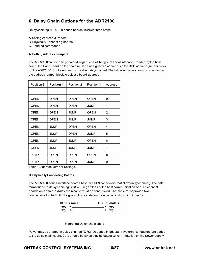
6. Daisy Chain Options for the ADR2100
Daisy chaining ADR2000 series boards involves three steps.
A. Setting Address Jumpers
B. Physically Connecting Boards
C. Sending commands
A. Setting Address Jumpers
The ADR2100 can be daisy-chained, regardless of the type of serial interface provided by the host
computer. Each board on the chain must be assigned an address via the BCD address jumper block
on the ADR2100. Up to ten boards may be daisy-chained. The following table shows how to jumper
the address jumper block to select a board address.
Position 8 Position 4 Position 2 Position 1 Address
OPEN OPEN OPEN OPEN 0
OPEN OPEN OPEN JUMP 1
OPEN OPEN JUMP OPEN 2
OPEN OPEN JUMP JUMP 3
OPEN JUMP OPEN OPEN 4
OPEN JUMP OPEN JUMP 5
OPEN JUMP JUMP OPEN 6
OPEN JUMP JUMP JUMP 7
JUMP OPEN OPEN OPEN 8
JUMP OPEN OPEN JUMP 9
Table 1. Address Jumper Settings.
B. Physically Connecting Boards
The ADR2100 series interface boards have two DB9 connectors that allow daisy chaining. The data
format used in daisy chaining is RS485 regardless of the host communication type. To connect
boards on a chain, a daisy chain cable must be constructed. The cable must provide two
connections for the RS485 signals. A typical daisy-chain cable is shown in Figure 5a)
Figure 5a) Daisy-chain cable
Power may be shared in daisy-chained ADR2100 series interfaces if two extra conductors are added
to the daisy-chain cable. Care should be taken that the output current limitation on the power supply
ONTRAK CONTROL SYSTEMS INC. 17/27 www.ontrak.net
is not exceeded. The connections for a powered daisy-chain cable are shown in Figure 5B) NOTE:
Power sharing is available only if power is applied via J2 ( 7-9VDC ).
Figure 5b) Powered Daisy-chain cable
The Daisy-chain cable can be connected from J3 to either J1 or J3 on additional ADR2100
interfaces. Both J1 and J3 have identical pinouts for RS485 and power signals used for daisy-chain
applications. Figure 5c) shows a typical daisy-chain application. If a Powered daisy-chain cable is
used, power need only be connected to J2 on any one ADR2100 in the chain.
Figure 5c) Typical Daisy-Chain Application
C Sending Commands
Once a board is jumpered, it will respond only to commands preceded by its address as a single
digit integer number. For example to read analog port 0 on board 3 the command “3RD0"<cr> is
sent. To set PA4 on board 7 the command “7SETPA4"<cr> is sent. Spaces sent between the
board address and commands are ignored. Board zero will respond to both commands with no
preceding address and commands preceded with a zero for reasons of continuity. Never connect two
boards with the same address on the same chain. This will result in both boards responding at the
same time and will cause contention on the network with possible damage to the ADR boards.
7. Interfacing to the ADR2100 ( Basic Examples )
The following interface examples show basic examples of interfacing various devices to the
ADR2100. Sample programs are written in BASIC and demonstrate proper command syntax.
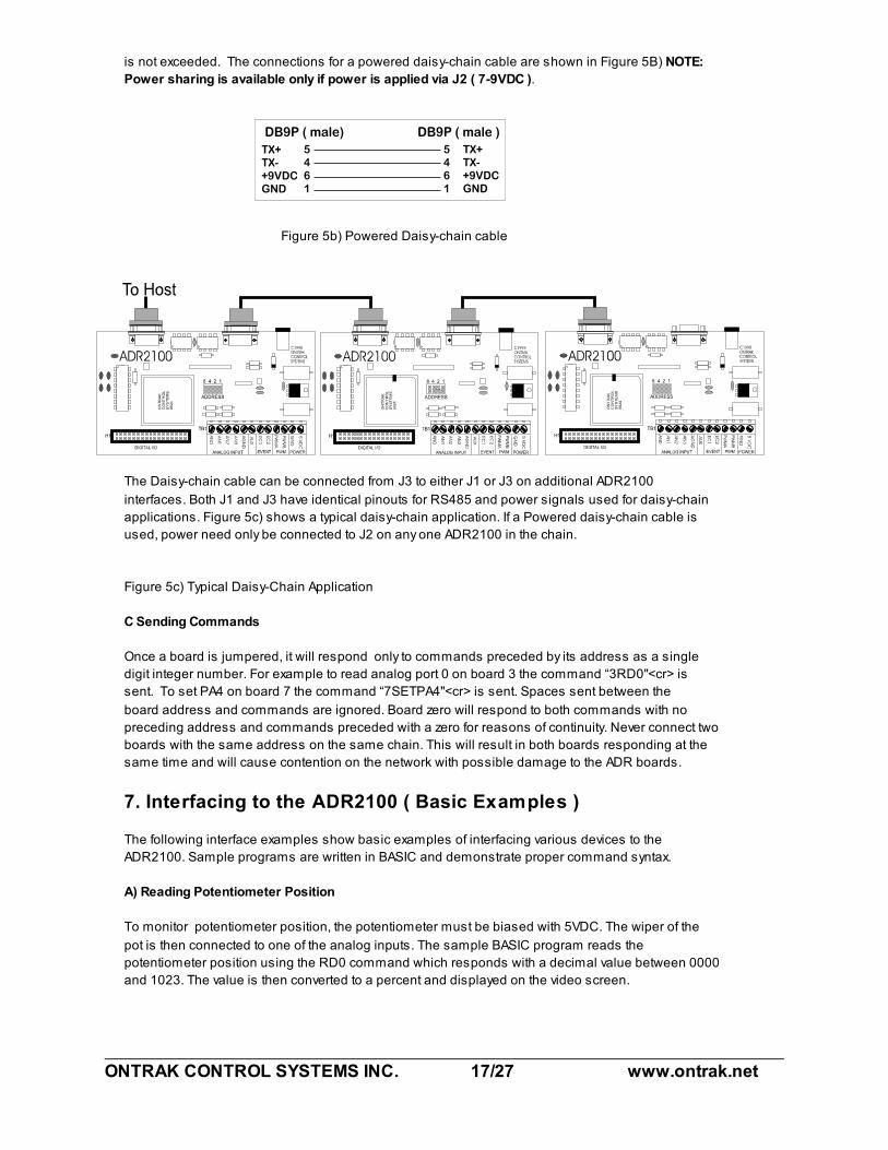
A) Reading Potentiometer Position
To monitor potentiometer position, the potentiometer must be biased with 5VDC. The wiper of the
pot is then connected to one of the analog inputs. The sample BASIC program reads the
potentiometer position using the RD0 command which responds with a decimal value between 0000
and 1023. The value is then converted to a percent and displayed on the video screen.
ONTRAK CONTROL SYSTEMS INC. 18/27 www.ontrak.net
10 OPEN”COM1:9600,N,8,1,CS,DS,RS” AS#1 ;open com port
20 CLS ;clear screen
30 LOCATE 1,1 ;locate cursor
40 PRINT#1, “RD0" ;send RD0 command to ADR2100
50 INPUT#1, POT ;retrieve data from ADR2100
60 POT=(POT/1023)*100 ;convert data to percent
70 PRINT “Potentiometer Position is”, POT ;display it
80 GOTO 30 ;repeat procedure
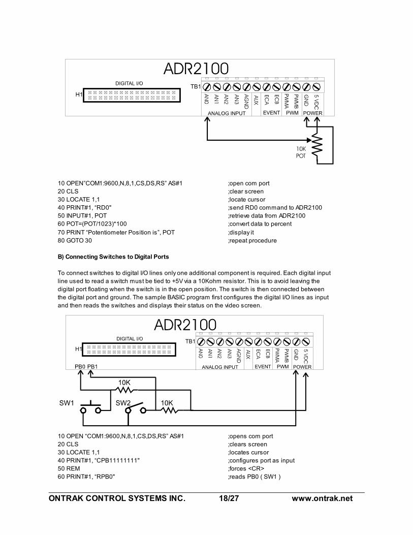
B) Connecting Switches to Digital Ports
To connect switches to digital I/O lines only one additional component is required. Each digital input
line used to read a switch must be tied to +5V via a 10Kohm resistor. This is to avoid leaving the
digital port floating when the switch is in the open position. The switch is then connected between
the digital port and ground. The sample BASIC program first configures the digital I/O lines as input
and then reads the switches and displays their status on the video screen.
10 OPEN “COM1:9600,N,8,1,CS,DS,RS” AS#1 ;opens com port
20 CLS ;clears screen
30 LOCATE 1,1 ;locates cursor
40 PRINT#1, “CPB11111111" ;configures port as input
50 REM ;forces <CR>
60 PRINT#1, “RPB0" ;reads PB0 ( SW1 )

ONTRAK CONTROL SYSTEMS INC. 19/27 www.ontrak.net
70 INPUT#1, SW1 ;saves status in variable SW1
80 PRINT#1, “RPB1" ;reads PB1 ( SW2 )
90 INPUT#1,SW2 ;saves status in variable SW2
100 T1$=”CLOSED” IF SW1=1 THEN T1$=”OPEN “ ;define T1$
110 T2$=”CLOSED” IF SW2=1 THEN T2$=”OPEN “ ;define T2$
120 PRINT “SW1 is “ T1$ ;print SW1 status
130 PRINT “SW2 is “ T2$ ;print SW2 status
140 GOTO 60 ;repeat procedure
Note: Switches connected to PA0,PA1,PA2 or PA3 do not require pull-up resistors as they are built
into those four inputs.
C) Connecting LED’s to Digital Ports
LED’s may be controlled using the digital I/O lines on the ADR2100. Only one additional component
is needed to drive LED’s. A current limit resistor is required for each LED with a value of around 220
Ohms. The LED is the turned on by resetting PB0 to a logic zero or turned off by setting PB0 to a
logic one. The sample BASIC program demonstrates how to turn the LED on and off.
10 OPEN “COM1:9600,N,8,1,CS,DS,RS” AS#1 ;opens com port
20 CLS ;clears screen
30 PRINT#1, “SETPB0" ;sets PB0*
40 REM ;forces <cr>
50 PRINT#1, “CPB11111110" ;configures PB0 as output
60 REM Turn on LED ;forces <cr>
70 PRINT#1, “RESPB0" ;turns on LED
80 REM Turn off LED ;forces <cr>
90 PRINT#1, “SETPB0" ;turns off LED
100 END
* PB0 remains in high impedance state until the CPB command is used to configure the port as
output.
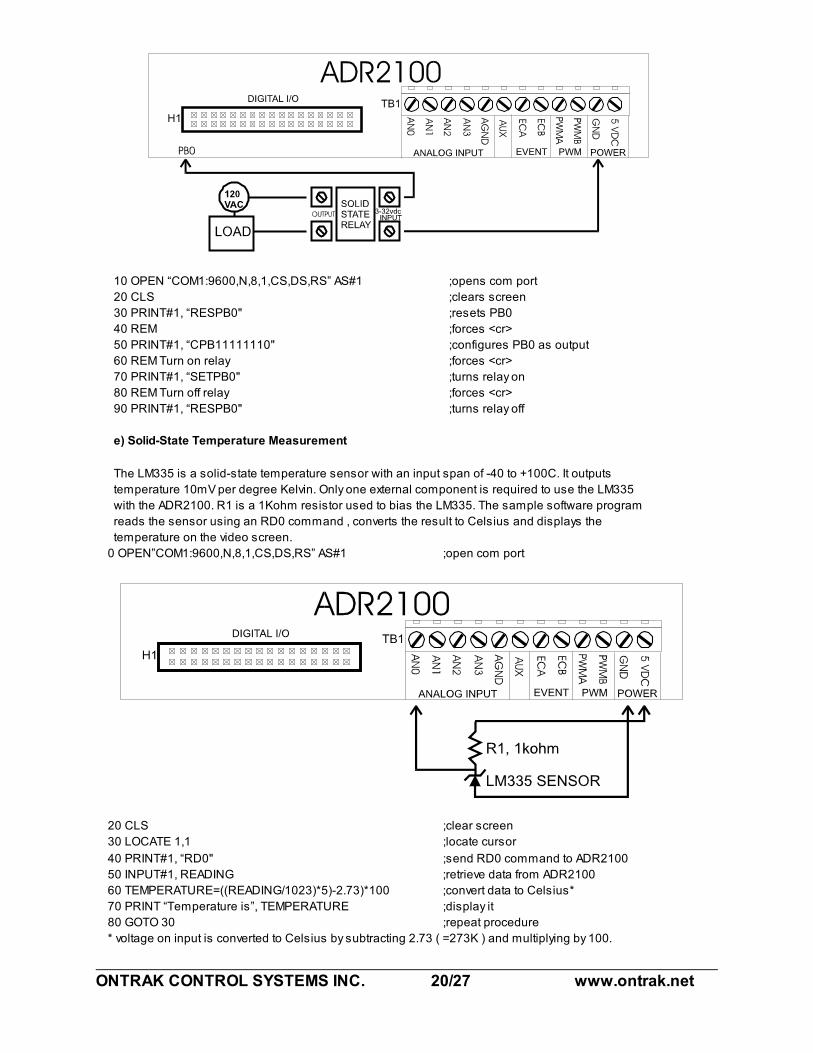
d) Driving Solid State Relays
Solid-State relays that require a DC voltage to operate may be driven by ADR2100 digital I/O lines
directly if the current input specification for the relay is 20mA or less. The relay must be rated for the
proper voltage and current required by the load. Each relay requires one digital I/O line to operate
and requires no other external components. The sample BASIC program demonstrates how the
relay is turned on. Note that the I/O line is RESET before the CPB command is used to configure
the port as output to avoid the relay turning on unexpectedly when the port is configured.
ONTRAK CONTROL SYSTEMS INC. 20/27 www.ontrak.net
10 OPEN “COM1:9600,N,8,1,CS,DS,RS” AS#1 ;opens com port
20 CLS ;clears screen
30 PRINT#1, “RESPB0" ;resets PB0
40 REM ;forces <cr>
50 PRINT#1, “CPB11111110" ;configures PB0 as output
60 REM Turn on relay ;forces <cr>
70 PRINT#1, “SETPB0" ;turns relay on
80 REM Turn off relay ;forces <cr>
90 PRINT#1, “RESPB0" ;turns relay off
e) Solid-State Temperature Measurement
The LM335 is a solid-state temperature sensor with an input span of -40 to +100C. It outputs
temperature 10mV per degree Kelvin. Only one external component is required to use the LM335
with the ADR2100. R1 is a 1Kohm resistor used to bias the LM335. The sample software program
reads the sensor using an RD0 command , converts the result to Celsius and displays the
temperature on the video screen.
0 OPEN”COM1:9600,N,8,1,CS,DS,RS” AS#1 ;open com port
20 CLS ;clear screen
30 LOCATE 1,1 ;locate cursor
40 PRINT#1, “RD0" ;send RD0 command to ADR2100
50 INPUT#1, READING ;retrieve data from ADR2100
60 TEMPERATURE=((READING/1023)*5)-2.73)*100 ;convert data to Celsius*
70 PRINT “Temperature is”, TEMPERATURE ;display it
80 GOTO 30 ;repeat procedure
* voltage on input is converted to Celsius by subtracting 2.73 ( =273K ) and multiplying by 100.
ONTRAK CONTROL SYSTEMS INC. 21/27 www.ontrak.net
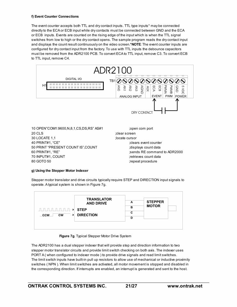
f) Event Counter Connections
The event counter accepts both TTL and dry contact inputs. TTL type inputs* may be connected
directly to the ECA or ECB input while dry contacts must be connected between GND and the ECA
or ECB inputs. Events are counted on the rising edge of the input which is when the TTL signal
switches from low to high or the dry contact opens. The sample program reads the dry contact input
and displays the count result continuously on the video screen.*NOTE: The event counter inputs are
configured for dry contact input from the factory. To use with TTL inputs the debounce capacitors
must be removed from the ADR2100 PCB. To convert ECA to TTL input, remove C3. To convert ECB
to TTL input, remove C4.
10 OPEN”COM1:9600,N,8,1,CS,DS,RS” AS#1 ;open com port
20 CLS ;clear screen
30 LOCATE 1,1 ;locate cursor
40 PRINT#1, “CE" ;clears event counter
50 PRINT “PRESENT COUNT IS”,COUNT ;displays count data
60 PRINT#1, “RE” ;sends RE command to ADR2000
70 INPUT#1, COUNT ;retrieves count data
80 GOTO 50 ;repeat procedure
g) Using the Stepper Motor Indexer
Stepper motor translator and drive circuits typically require STEP and DIRECTION input signals to
operate. A typical system is shown in Figure 7g.
Figure 7g. Typical Stepper Motor Drive System
The ADR2100 has a dual stepper indexer that will provide step and direction information to two
stepper motor translator circuits and provide limit switch checking on both axis. The indexer uses
PORT A ( when configured to indexer mode ) to provide drive signals and read limit switches.
The limit switch inputs have built-in pull up resistors to allow use of mechanical or inductive proximity
switches ( NPN ). When limit switches are activated, all motor movement is stopped and disabled in
the corresponding direction. If interrupts are enabled, an interrupt is generated and sent to the host.
ONTRAK CONTROL SYSTEMS INC. 22/27 www.ontrak.net
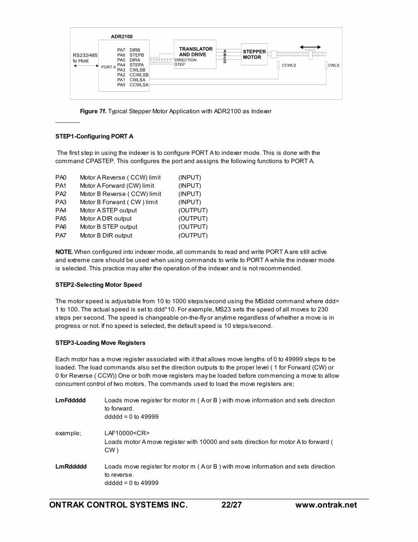
Figure 7f. Typical Stepper Motor Application with ADR2100 as Indexer
STEP1-Configuring PORT A
The first step in using the indexer is to configure PORT A to indexer mode. This is done with the
command CPASTEP. This configures the port and assigns the following functions to PORT A.
PA0 Motor A Reverse ( CCW) limit (INPUT)
PA1 Motor A Forward (CW) limit (INPUT)
PA2 Motor B Reverse ( CCW) limit (INPUT)
PA3 Motor B Forward ( CW ) limit (INPUT)
PA4 Motor A STEP output (OUTPUT)
PA5 Motor A DIR output (OUTPUT)
PA6 Motor B STEP output (OUTPUT)
PA7 Motor B DIR output (OUTPUT)
NOTE. When configured into indexer mode, all commands to read and write PORT A are still active
and extreme care should be used when using commands to write to PORT A while the indexer mode
is selected. This practice may alter the operation of the indexer and is not recommended.
STEP2-Selecting Motor Speed
The motor speed is adjustable from 10 to 1000 steps/second using the MSddd command where ddd=
1 to 100. The actual speed is set to ddd*10. For example, MS23 sets the speed of all moves to 230
steps per second. The speed is changeable on-the-fly or anytime regardless of whether a move is in
progress or not. If no speed is selected, the default speed is 10 steps/second.
STEP3-Loading Move Registers
Each motor has a move register associated with it that allows move lengths of 0 to 49999 steps to be
loaded. The load commands also set the direction outputs to the proper level ( 1 for Forward (CW) or
0 for Reverse ( CCW)) One or both move registers may be loaded before commencing a move to allow
concurrent control of two motors. The commands used to load the move registers are;
LmFddddd Loads move register for motor m ( A or B ) with move information and sets direction
to forward.
ddddd = 0 to 49999
example; LAF10000<CR>
Loads motor A move register with 10000 and sets direction for motor A to forward (
CW )
LmRddddd Loads move register for motor m ( A or B ) with move information and sets direction
to reverse.
ddddd = 0 to 49999
ONTRAK CONTROL SYSTEMS INC. 23/27 www.ontrak.net
example; LBR4400<CR>
Loads motor B move register with 4400 and sets direction for motor B to reverse (
CCW )
If a number is not specified in the command string ( ex. LAF,LAR,LBF,LBR ) the indexer is set for
continuous move operation and will run until a limit is reached or an emergency stop command is
sent. Typically, move registers are loaded before a move is started, however, they may be loaded
while the indexer is operating to extend moves. The registers may be read back using the QA or QB
command whether the indexer is operating or not. This allows the host to monitor moves in operation.
STEP4- Starting a Move.
Once the move registers are loaded and the speed is selected, a move may be started. The
command to start a move is G ( GO command ). Once initiated, the indexer will begin the move and
decrement the move registers with each step. The move will continue until all move registers are zero
or a limit is reached. If a limit is reached, all movement stops and cannot be restarted until new move
information is loaded into the move registers and a new GO command is given.
STEP5-Stopping a Move.
Once a move is started it will terminate in one of two ways. The first is if after the move registers
decrement to zero meaning the move was successfully completed. The second is if the host sends
an E ( emergency stop ) command. In this case the motors will stop and move registers maintain
present count values and may be restarted by sending a G ( GO command ).
Using Interrupts with the Stepper Motor Indexer
Interrupts may be used to signal the host that a move has been completed or a limit switch has been
activated. See section 7h for details
7h) Using Interrupt Functions
The ADR2100 has interrupt capabilities using the first four bits of PORT A ( PA0,PA1,PA2,PA3). All
four bits have built-in weak pull-ups when configured as digital inputs to facilitate contact inputs. The
Interrupts operate in two modes determined by the mode of PORT A.
STANDARD MODE
In standard mode ( PORT A configured as digital I/O with no stepper indexer functions ) the interrupts
can be used to signal the host when a digital I/O line is brought low by an external event such as a
key press. The inputs are scanned 10,000 times per second requiring a pulse width of 100us to
guarantee an interrupt. When interrupts are enabled, the host will return a two digit integer code upon
interrupt where the first digit is the board address and the second digit is the interrupt number. The
interrupt number corresponds to the digital I/O line that generated the interrupt as follows;
PA0 1
PA1 2
PA2 3
PA3 4
For example, if an interrupt is generated by PA2 brought low on board 0, the ADR2100 will return 03
<cr>. Or if PA0 is brought low on board 3 the ADR2100 will return 31<cr>
Interrupts are enabled using the command “IE” and must be enabled after the ”CPAxxxxxxxx” is
used to configure the port. When the port is configured using the “CPAxxxxxxxx” command,

ONTRAK CONTROL SYSTEMS INC. 24/27 www.ontrak.net
interrupts are disabled.
Once an interrupt is generated for a particular I/O line, it is masked and no longer checked until re-
enabled by an “IE” command sent by the host.
Interrupts may be disabled using the “ID” command. Care should be exercised In disabling interrupts
as the “ID” command may “collide” with interrupt data being sent by the ADR2100 if an interrupt is
generated at that instant. Because of this, the command “IS” ( interrupt status ) is provided to query
the ADR2100 as to the status of its interrupts. This command returns a “1" if the interrupts are
enabled or a “0" if they are disabled. The “IS” command should be used after the “ID” command to
verify interrupts are disabled.
STEPPER INDEXER MODE
If the ADR2100 PORT A is operating in stepper indexer mode, the interrupt functions operate to alert
the host to a limit switch being activated or the successful completion of a move. The inputs are
checked before each step and thus the scan rate is set by the actual motor speed setting. The
interrupts will return a two digit code where the first digit is the board address ( 0-9 ) and the second
digit indicates a successful move or a limit switch being activated as per table below;
( board address is zero)
CODE Cause
00 Indicates successful move completion
01 Motor A Reverse limit ( CCW ) reached
02 Motor A Forward limit ( CW ) reached
03 Motor B Reverse limit ( CCW ) reached
04 Motor B Forward limit ( CW ) reached
Once an interrupt is generated, the motors can not be restarted until new information is loaded into
the move registers. Interrupts need not be re-enabled after each move. They are only disabled if the
“ID” command is sent or the port is configured to another mode using the “CPAxxxxxxxx” command.

ONTRAK CONTROL SYSTEMS INC. 25/27 www.ontrak.net
APPENDIX A CONNECTION DIAGRAM
ONTRAK CONTROL SYSTEMS INC. 26/27 www.ontrak.net
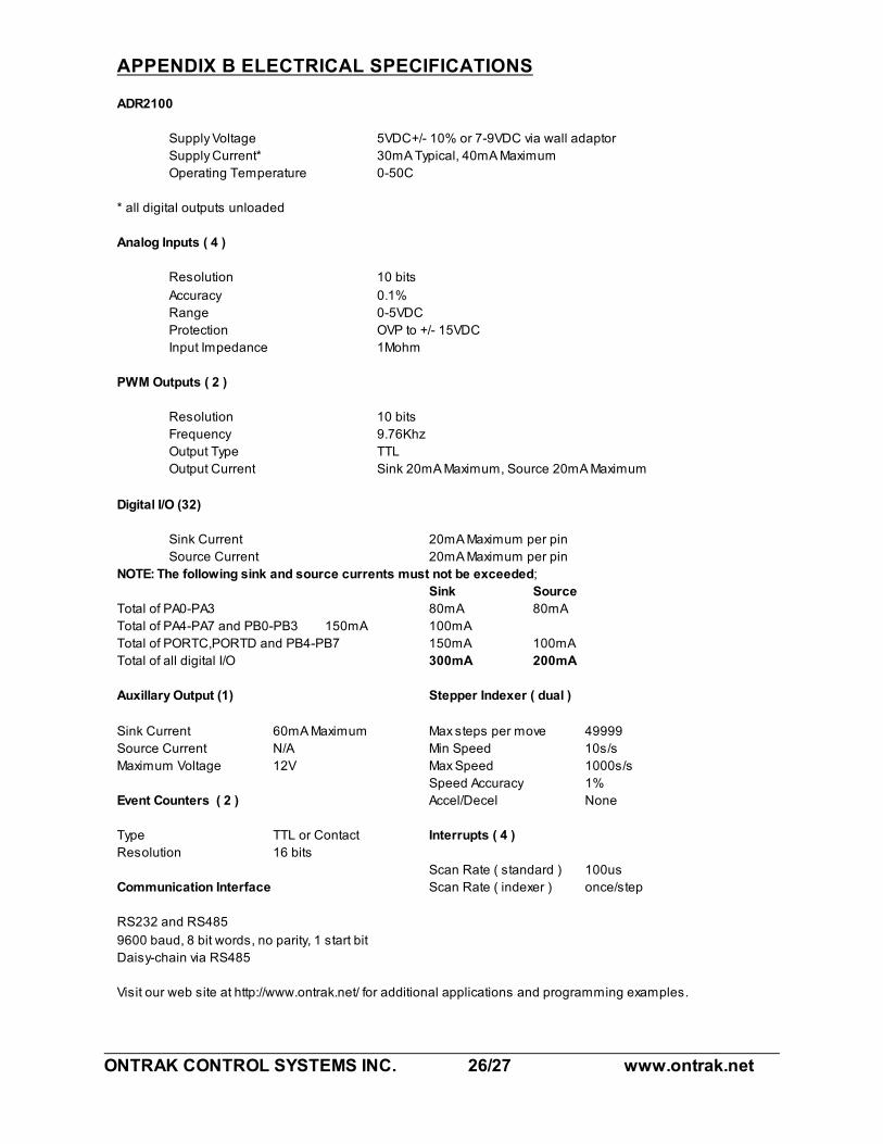
APPENDIX B ELECTRICAL SPECIFICATIONS
ADR2100
Supply Voltage 5VDC+/- 10% or 7-9VDC via wall adaptor
Supply Current* 30mA Typical, 40mA Maximum
Operating Temperature 0-50C
* all digital outputs unloaded
Analog Inputs ( 4 )
Resolution 10 bits
Accuracy 0.1%
Range 0-5VDC
Protection OVP to +/- 15VDC
Input Impedance 1Mohm
PWM Outputs ( 2 )
Resolution 10 bits
Frequency 9.76Khz
Output Type TTL
Output Current Sink 20mA Maximum, Source 20mA Maximum
Digital I/O (32)
Sink Current 20mA Maximum per pin
Source Current 20mA Maximum per pin
NOTE: The following sink and source currents must not be exceeded;
Sink Source
Total of PA0-PA3 80mA 80mA
Total of PA4-PA7 and PB0-PB3 150mA 100mA
Total of PORTC,PORTD and PB4-PB7 150mA 100mA
Total of all digital I/O 300mA 200mA
Auxillary Output (1) Stepper Indexer ( dual )
Sink Current 60mA Maximum Max steps per move 49999
Source Current N/A Min Speed 10s/s
Maximum Voltage 12V Max Speed 1000s/s
Speed Accuracy 1%
Event Counters ( 2 ) Accel/Decel None
Type TTL or Contact Interrupts ( 4 )
Resolution 16 bits
Scan Rate ( standard ) 100us
Communication Interface Scan Rate ( indexer ) once/step
RS232 and RS485
9600 baud, 8 bit words, no parity, 1 start bit
Daisy-chain via RS485
Visit our web site at http://www.ontrak.net/ for additional applications and programming examples.

ONTRAK CONTROL SYSTEMS INC. 27/27 www.ontrak.net
APPENDIX C MOUNTING DIMENSIONS