Embed Size (px)
Citation preview
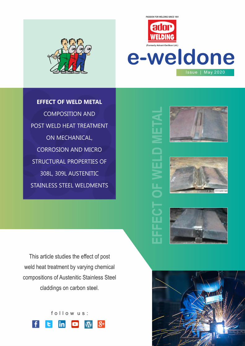
e-weldoneIssue | May 2020
f o l l o w u s :
PASSION FOR WELDING SINCE 1951
EF
FE
CT
OF
WE
LD
ME
TAL
EFFECT OF WELD METAL
COMPOSITION AND
POST WELD HEAT TREATMENT
ON MECHANICAL,
CORROSION AND MICRO
STRUCTURAL PROPERTIES OF
308L, 309L AUSTENITIC
STAINLESS STEEL WELDMENTS
This article studies the effect of post
weld heat treatment by varying chemical
compositions of Austenitic Stainless Steel
claddings on carbon steel.
ABSTRACT
Austenitic stainless steels (ASS) are widely used material in nuclear reactors and power plants because of their good
ductility, excellent corrosion resistance and reasonable weld ability. But, to reduce the construction cost of vessels,
stainless steel (SS) base metal is replaced by Carbon or low alloy steel and SS was cladded above the carbon steel for
corrosion resistance. During cladding or welding, internal stresses are formed in the base metal. To remove those
stresses, cladded base metal parts are post weld heat treated at 620°C & 690°C for 1hour. ASS weld metal contains some
amount of ferrite to reduce the hot cracking. During Post weld heat treatment ferrite content in the weld metal is
transformed into chromium rich secondary phases. These secondary phases make chromium depletion zones around
them. The chromium depletion zones led to intergranular corrosion and affect the mechanical properties of the weld
metal. The transformations of secondary phases depend on ferrite number of weld metal. Hence, the ferrite number was
varied to achieve better mechanical property and corrosion resistance of weld metal. In this work, two different grades
(AISI 308L, 309L) of austenitic stainless steel electrodes are manufactured to 6 different types to attain different ferrite
number weld metal by changing chemical composition through flux. The properties of undiluted weld metal are
evaluated before and after post weld heat treatment condition of 620°C & 690°C for 1hour. This thesis reports the effect
of PWHT on impact toughness properties, lateral expansion, ferrite number, corrosion properties and micro structural
properties of E308L, E309L weld metals with different ferrite numbers. From this investigation, it is found that mechanical
properties of the high ferrite number weld metal drastically changed compared to low ferrite number weld metal.
KEYWORDS: 308L, 309L austenitic stainless steel, ferrite number, post weld heat treatment, impact toughness, micro
structural properties
f o l l o w u s :
www.adorwelding.com
e-weldoneIssue | May 2020
PASSION FOR WELDING SINCE 1951
EFFECT OF WELD METAL COMPOSITION AND POST WELD HEAT TREATMENT ON MECHANICAL,
CORROSION AND MICRO STRUCTURAL PROPERTIES OF 308L, 309L AUSTENITIC STAINLESS STEEL WELDMENTS
1. INTRODUCTION
Austenitic stainless steel is widely used among stainless steel
group because of the properties of easily weldable and
formable. They are most easily recognized as nonmagnetic. A
literature survey indicates austenitic stainless steel used as
electrodes for the welding of heavy structures in ship building,
pressure vessels and heavy vehicles, in order to meet the
requirement of good impact properties along with
adequate strength [1]. Austenitic stainless steel had less than
0.15% carbon, 16 to 28% chromium and 9 to 30 % nickel.
Chromium reacts with the atmosphere oxygen and form passive
layer of chromium oxide. It prevents the further oxidation and
nickel is enhancing the property of the toughness at cryogenic
temperature. Austenitic stainless steels are indicated by 200 and
300 series. Austenitic stainless steel weldments are solidified as
austenite as their primary phase and small amount of ferrite
[2],[3]. This ferrite was act as barrier to hot cracks, small fissures
during solidification of weld zone. Fissures size and amount in
the weldment is indirectly proportional to amount of ferrite
present on the weldment [4]. The most widely used austenite
steel electrode is the E308L, E309L also known as 18/9, 22/12 for
its composition of 18% chromium, 9% nickel and 22%
chromium, 12% nickel. By varying the chemical composition of
the 308L, 309L weld metal within the range mentioned in the
ASME SEC II, ferrite content is changed. Post weld heat
treatment is the stress relieving process and during this
process weldment and HAZ is heated near to critical
temperature and kept for some time based on material
thickness. Then cooled slowly to room temperature during post
weld heat treatment strength of the material is increase [5].
The two major problems that arise during depositing of the
austenitic stainless steel electrodes are hot cracking and
sensitization. Low melting impurities such as sulphur (S),
phosphorous (P) are reason for the hot cracking in austenitic
stainless steel weld metal. Which tend to penetrate grain
boundaries during welding and generating cracks and
shrinkage stress during solidification of weldmetal. This problem
can be controlled by adjusting the composition of the filler
material to obtain a δ-ferrite in the austenite matrix [3]. Heat
input or cooling rate of the weld metal also have some influence
on the ferrite formation, but chemical composition have more
influence on changing ferrite level in weldment compared to
heat input [6]. The ferrite provides ferrite-austenite grain
boundaries, which are able to control the sulphur and
phosphorous compounds and hot cracking.
f o l l o w u s :
www.adorwelding.com
e-weldoneIssue | May 2020
PASSION FOR WELDING SINCE 1951
If austenitic stainless steels will extensively heated or slowly
cooled in the temperature range of 450˚C to 850˚C, chromium
rich secondary phases like metal carbides, chi phase and sigma
phase are precipitate along the grain boundaries of the ferrite in
the weldment leading to chromium depletion in the vicinity of
the grain boundaries, this phenomenon is called sensitization
[7-13]. The chromium depletion vicinity area in the aged
material is directly proportional to aged time and temperature
[14]. These secondary phases were reduces the Corrosion and
mechanical properties like toughness and ductility of the
austenitic stainless steel weldment drastically [5], [15], [16].
Some chemical elements like molybdenum, silicon are promotes
these secondary phase formation and copper will delays the
secondary phase formation [17]. During aging, if ferrite grain
boundary has low carbon content, chi and sigma phases will
form. Otherwise metal carbides will form before chi and sigma
phase formation. Chi phase will fully converted in to sigma phase
by long time of aging [11]. This problem is controlled by
adjusting the ferrite content and ferrite morphology in the
austenite matrix weldment.
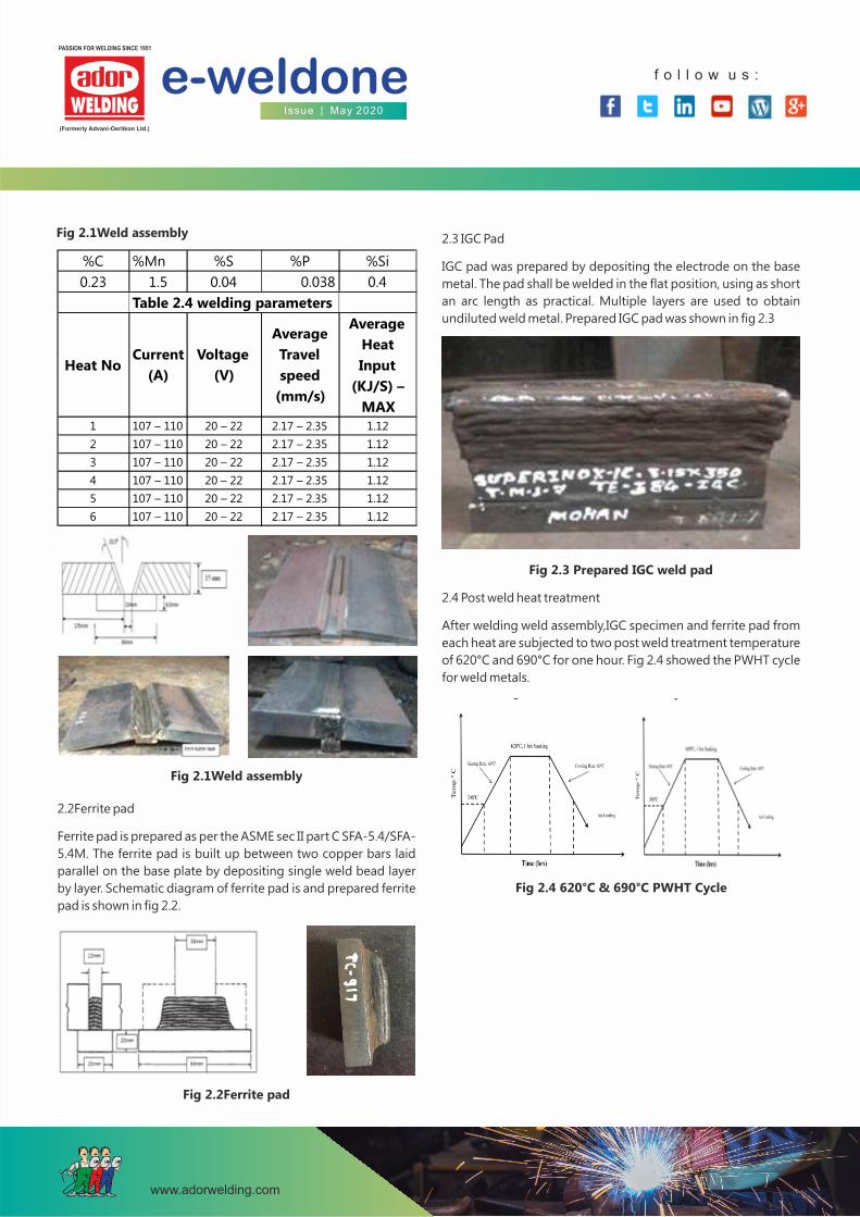
2. EXPERIMENTAL WORK 2.1 WELD ASSEMBLY
308L and 309L bare wire is used to produce electrodes in this
project work. Chemical composition of the bare wire is showed
in the table 2.1. These 2 wires are made in to 6 different austenitic
stainless steel ferrite number weld metal by varying the chemical
composition through flux. Chemical composition of the 6
different ferrite number weldmetal is shown in the table 2.2.
Heat no 1-3 indicates 308L and heat no 4 – 6 indicates 309L weld
metal chemical composition. C-Mn steel (IS 2062 grade B) is
used as base material and 3.15 × 350 mm austenitic stainless
steel electrode was used to make SMAW joints. The chemical
composition of the base metal is shown in table 2.3. IS 2062
material is used as base metal for weld assembly, ferrite pad and
IGC pad.
C-Mn steel, 15 mm thickness is used for fabrication of single 'V'
but joint configuration as shown in Figure 2.1. Welding
parameters like root gap, Bevel angle, Interpass temperature,
Back plate and Base plate dimensions are selected as per the
ASME section II C – SFA 5.4. The base material IS 2062 used in the
present investigation at the size of 300mm X 125mm X 15mm
and Backing plate of size 370mm X 30mm X6.5mm. The initial
joint configuration was obtained by securing the plates in
position using tack welding. After tack welding 3mm butter layer
is added to base metal to prevent the dilution of the base metal
into weld metal. Interpass temperature was maintained at
maximum of 150°C. The process parameters used in the
fabrication of joints are presented in Table 2.4. Then weld is
made Plates are welded in flat (1G) position and DCEP polarity
was used.
The welded joints are sliced and machined to required
dimensions for preparing impact and micro specimens under
(American Society for Testing of Materials) ASTM guidelines.
Table 2.1 Bare wire Chemical Composition
%C %Cr %Ni %Mo %Mn %Si %P %S %Cu %Nb %N
308L 0.022 19.75 9.2 0.176 1.51 0.42 0.028 0.01 0.102 0.02 0.064
309L 0.025 23.48 12.98 0.011 1.83 0.41 0.016 0.01 0.104 0.03 0.084
BARE
WIRE
Table 2.2 308L & 309L electrode Chemical Composition
Table 2.3 Base material Chemical Composition
Heat WRC
No FN
1 0.036 19.5 9.6 0.103 0.91 0.45 0.034 0.01 0.074 0.038 0.086 4
2 0.037 19.98 9.54 0.065 0.89 0.43 0.039 0.01 0.046 0.038 0.082 7
3 0.032 20.69 9.31 0.235 0.94 0.42 0.033 0.01 0.17 0.04 0.08 11
4 0.03 22.59 13.06 0.304 1.47 0.7 0.027 0.02 0.166 0.047 0.104 6
5 0.037 23.56 12.82 0.302 1.5 0.77 0.017 0.014 0.103 0.042 0.11 9.5
6 0.038 24.47 12.8 0.302 1.58 0.77 0.024 0.024 0.106 0.046 0.106 13
%P %S %Cu %Nb %N%C %Cr %Ni %Mo %Mn %Si
f o l l o w u s :
www.adorwelding.com
e-weldoneIssue | May 2020
PASSION FOR WELDING SINCE 1951
%C %Mn %S %P %Si
0.23 1.5 0.04 0.038 0.4
Table 2.4 welding parameters
Heat NoCurrent
(A)
Voltage
(V)
Average
Travel
speed
(mm/s)
Average
Heat
Input
(KJ/S) –
MAX
1 107 – 110 20 – 22 2.17 – 2.35 1.12
2 107 – 110 20 – 22 2.17 – 2.35 1.12
3 107 – 110 20 – 22 2.17 – 2.35 1.12
4 107 – 110 20 – 22 2.17 – 2.35 1.12
5 107 – 110 20 – 22 2.17 – 2.35 1.12
6 107 – 110 20 – 22 2.17 – 2.35 1.12
Fig 2.1Weld assembly
2.2Ferrite pad
Ferrite pad is prepared as per the ASME sec II part C SFA-5.4/SFA-
5.4M. The ferrite pad is built up between two copper bars laid
parallel on the base plate by depositing single weld bead layer
by layer. Schematic diagram of ferrite pad is and prepared ferrite
pad is shown in fig 2.2.
Fig 2.2Ferrite pad
2.3 IGC Pad
IGC pad was prepared by depositing the electrode on the base
metal. The pad shall be welded in the flat position, using as short
an arc length as practical. Multiple layers are used to obtain
undiluted weld metal. Prepared IGC pad was shown in fig 2.3
Fig 2.1Weld assembly
Fig 2.3 Prepared IGC weld pad
2.4 Post weld heat treatment
After welding weld assembly,IGC specimen and ferrite pad from
each heat are subjected to two post weld treatment temperature
of 620°C and 690°C for one hour. Fig 2.4 showed the PWHT cycle
for weld metals.
Fig 2.4 620°C & 690°C PWHT Cycle
f o l l o w u s :
www.adorwelding.com
e-weldoneIssue | May 2020
PASSION FOR WELDING SINCE 1951
Fig 2.5 IGC specimen
3. RESULTS
3.1 Ferrite number
Ferrite numbers of each heat weldments is measured by
ferritescope before and after post weld heat treatment and
listed in table 3.1. From the results we know that ferrite number
of the weld is reduced after post weld heat treatment. Reduction
percentage of ferrite number is increase with increasing post
weld heat treatment temperature from 620 to 690 °C. It shows
that secondary phase formation increased with post weld heat
treatment temperature.
In 308L weld metal high amount of ferrite was transformed into
secondary phases in high ferrite weldment (FN 11) compared to
low ferrite weldment (FN 4). But, During PWHT high percentage
of ferrite in the low ferrite weldment (FN 4) will be transformed
into 55% of secondary phases compared to high ferrite
weldment (FN 11) transformed into only 45 % of secondary
phases at post weld heat treatment temperature of 690 °C. In
309L material ferrite reduction rate was high in the high ferrite
number weld metal due to high amount of chromium content.
2.5 Sample preparation
Test samples are prepared with dimensions and tested as per the
ASTM E23 standard. From each assembly, impact samples are
prepared with specified dimensions. The Charpy impact test was
conducted at -20°C using a pendulum type impact testing
machine.
The microstructure of weldments was analyzed using a light
optical microscope. The specimens after polishing to mirror
finish then etched with combination of distilled water – 70ml,
HCL – 15ml and HNO3 – 5ml was specified in ASTM E407 is used
to reveal the microstructure. IGC specimens are prepared with
dimensions mentioned in the ASTM E262 standard and
prepared. IGC specimens are shown in fig 2.5. Corrosion rate was
measured by following formulae Corrosion rate (Millimeters per
month) = (7305×W)
(D×A×T)
Table 3.1 Ferrite number According to Ferritescope and
WRC-1992(FN) Diagram
ELECTRODE
TYPE HEAT
NO
FERRITE
NUMBER
FOR
WRC1992
DIAGRAM
Ferritescope
As Weld
condition PWHT
@
620°C PWHT
@
690°C
308L
1
4
7.7
4.5
3.4
2
7
9.7
6.3
4.7
3 11 12.8 8.8 6.8
309L
4 6 6.5 5.1 3.5
5 9 9 6.8 2.9
6 13 12.6 9.5 2.3
3.2 Impact properties
The Charpy impact toughness value and lateral expansion are
observed to all heat at as weld condition and post weld heat
treated specimens at - 20°C and found that low ferrite number
weld have high toughness compared to high ferrite weld. For
each heat number, as welded joints have higher toughness when
compared to post weld heat treated weld joints. Ferrite is brittle
phase compared to austenite. So toughness was reduced while
increasing ferrite content. When the weldment is subjected to
post weld heat treatment chromium rich secondary phases like
chromium carbide, chi phase and sigma phase are formed. It will
reduce the ductility and toughness drastically.
ELECTRODE
TYPE HEAT NO
FERRITE
NUMBER
As weld
condition
(JOULE)
PWHT @
620°C
(JOULE)
PWHT @
690°C
(JOULE)
308L
1
4
80
68
60
2 7 74 62 58
3
11
68
60
56
309L
4
6
63
56
11
5 9 55 47 08
6 13 52 38 07
Table 3.2 Impact toughness value at – 20 °C
ELECTRODE
TYPE
HEAT
NO
FERRITE
NUMBER
As weld
condition
(mm)
PWHT @
620°C
(mm)
PWHT @
690°C
(mm)
308L
1
4
1.35
1.19 1.07
2 7 1.27 1.11 1.02
3
11
1.14
1.05 0.94
309L
4
6
1.05
0.91 0.37
5 9 0.91 0.70 0.33
6 13 0.82 0.65 0.30
Table 3.2 Impact toughness value at – 20 °C
f o l l o w u s :
www.adorwelding.com
e-weldoneIssue | May 2020
PASSION FOR WELDING SINCE 1951
Table 3.4 shows IGC practice E results. In 308L all ferrite number
electrode at all weld conditions are passed without any fissures
and cracks formation in IGC practice E. In 309L all ferrite number
electrode weld metal at as weld condition was passed. At post
weld heat treated condition of 690°C for 1 hour all ferrite
number welds are failed. Because formation of secondary phase
was faster in 690°C PWHT temperature compared to 620°C
PWHT temperature.
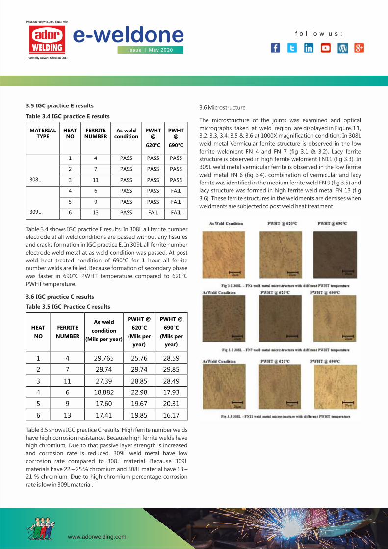
3.6 Microstructure
The microstructure of the joints was examined and optical
micrographs taken at weld region are displayed in Figure.3.1,
3.2, 3.3, 3.4, 3.5 & 3.6 at 1000X magnification condition. In 308L
weld metal Vermicular ferrite structure is observed in the low
ferrite weldment FN 4 and FN 7 (fig 3.1 & 3.2). Lacy ferrite
structure is observed in high ferrite weldment FN11 (fig 3.3). In
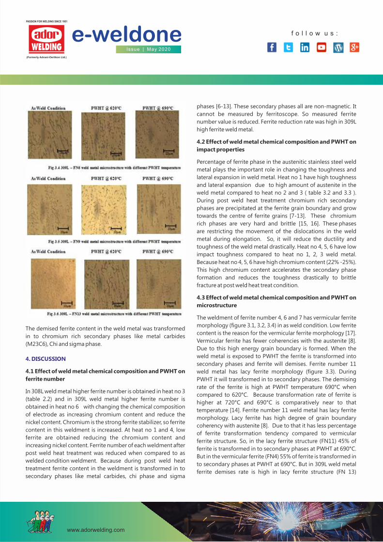
309L weld metal vermicular ferrite is observed in the low ferrite
weld metal FN 6 (fig 3.4), combination of vermicular and lacy
ferrite was identified in the medium ferrite weld FN 9 (fig 3.5) and
lacy structure was formed in high ferrite weld metal FN 13 (fig
3.6). These ferrite structures in the weldments are demises when
weldments are subjected to post weld heat treatment.
3.5 IGC practice E results
Table 3.4 IGC practice E results
MATERIAL TYPE
HEAT NO
FERRITE NUMBER
As weld condition
PWHT@
620°C
PWHT@
690°C
308L
1
4
PASS
PASS PASS
2 7 PASS PASS PASS
3
11
PASS
PASS PASS
309L
4
6
PASS
PASS FAIL
5 9 PASS PASS FAIL
6 13 PASS FAIL FAIL
3.6 IGC practice C results
Table 3.5 IGC Practice C results
HEAT
NO
FERRITE
NUMBER
As weld
condition
(Mils per year)
PWHT @
620°C
(Mils per
year)
PWHT @
690°C
(Mils per
year)
1 4 29.765 25.76 28.59
2 7 29.74 29.74 29.85
3 11 27.39 28.85 28.49
4 6 18.882 22.98 17.93
5 9 17.60 19.67 20.31
6 13 17.41 19.85 16.17
Table 3.5 shows IGC practice C results. High ferrite number welds
have high corrosion resistance. Because high ferrite welds have
high chromium, Due to that passive layer strength is increased
and corrosion rate is reduced. 309L weld metal have low
corrosion rate compared to 308L material. Because 309L
materials have 22 – 25 % chromium and 308L material have 18 –
21 % chromium. Due to high chromium percentage corrosion
rate is low in 309L material.
f o l l o w u s :
www.adorwelding.com
e-weldoneIssue | May 2020
PASSION FOR WELDING SINCE 1951
The demised ferrite content in the weld metal was transformed
in to chromium rich secondary phases like metal carbides
(M23C6), Chi and sigma phase.
4. DISCUSSION
4.1 Effect of weld metal chemical composition and PWHT on
ferrite number
In 308L weld metal higher ferrite number is obtained in heat no 3
(table 2.2) and in 309L weld metal higher ferrite number is
obtained in heat no 6 with changing the chemical composition
of electrode as increasing chromium content and reduce the
nickel content. Chromium is the strong ferrite stabilizer, so ferrite
content in this weldment is increased. At heat no 1 and 4, low
ferrite are obtained reducing the chromium content and
increasing nickel content. Ferrite number of each weldment after
post weld heat treatment was reduced when compared to as
welded condition weldment. Because during post weld heat
treatment ferrite content in the weldment is transformed in to
secondary phases like metal carbides, chi phase and sigma
phases [6-13]. These secondary phases all are non-magnetic. It
cannot be measured by ferritoscope. So measured ferrite
number value is reduced. Ferrite reduction rate was high in 309L
high ferrite weld metal.
4.2 Effect of weld metal chemical composition and PWHT on
impact properties
Percentage of ferrite phase in the austenitic stainless steel weld
metal plays the important role in changing the toughness and
lateral expansion in weld metal. Heat no 1 have high toughness
and lateral expansion due to high amount of austenite in the
weld metal compared to heat no 2 and 3 ( table 3.2 and 3.3 ).
During post weld heat treatment chromium rich secondary
phases are precipitated at the ferrite grain boundary and grow
towards the centre of ferrite grains [7-13]. These chromium
rich phases are very hard and brittle [15, 16]. These phases
are restricting the movement of the dislocations in the weld
metal during elongation. So, it will reduce the ductility and
toughness of the weld metal drastically. Heat no 4, 5, 6 have low
impact toughness compared to heat no 1, 2, 3 weld metal.
Because heat no 4, 5, 6 have high chromium content (22% -25%).
This high chromium content accelerates the secondary phase
formation and reduces the toughness drastically to brittle
fracture at post weld heat treat condition.
4.3 Effect of weld metal chemical composition and PWHT on
microstructure
The weldment of ferrite number 4, 6 and 7 has vermicular ferrite
morphology (figure 3.1, 3.2, 3.4) in as weld condition. Low ferrite
content is the reason for the vermicular ferrite morphology [17].
Vermicular ferrite has fewer coherencies with the austenite [8].
Due to this high energy grain boundary is formed. When the
weld metal is exposed to PWHT the ferrite is transformed into
secondary phases and ferrite will demises. Ferrite number 11
weld metal has lacy ferrite morphology (figure 3.3). During
PWHT it will transformed in to secondary phases. The demising
rate of the ferrite is high at PWHT temperature 690°C when
compared to 620°C. Because transformation rate of ferrite is
higher at 720°C and 690°C is comparatively near to that
temperature [14]. Ferrite number 11 weld metal has lacy ferrite
morphology. Lacy ferrite has high degree of grain boundary
coherency with austenite [8]. Due to that it has less percentage
of ferrite transformation tendency compared to vermicular
ferrite structure. So, in the lacy ferrite structure (FN11) 45% of
ferrite is transformed in to secondary phases at PWHT at 690°C.
But in the vermicular ferrite (FN4) 55% of ferrite is transformed in
to secondary phases at PWHT at 690°C. But in 309L weld metal
ferrite demises rate is high in lacy ferrite structure (FN 13)
f o l l o w u s :
www.adorwelding.com
e-weldoneIssue | May 2020
PASSION FOR WELDING SINCE 1951
5. 309L weld metal has high corrosion resistance compared to
308L weld metal. After PWHT 309L corrosion resistance is
further increased.
ACKNOWLEDGEMENTS
The authors are thankful to ADOR WELDING, PUNE for providing
base material, electrodes and extending fabrication facility for
joint fabrication providing testing facilities to carry out this
investigation.
REFERENCES
1) E. R. SZUMACHOWSKI AND H. F. REID, THE WELDING
IOURNAL, Cryogenic Toughness of SMA Austenitic Stainless
Steel Weld Metals Introduction Part I —Role of Ferrite,
NOVEMBER 1978.
2) G. L. LEONE AND H. W. KERR, WELDING RESEARCH
SUPPLEMENT, The Ferrite to Austenite Transformation in
Stainless Steels, JANUARY 1982-13s.
3) V. P. KUJANPAA, S. A. DAVID AND C. L. WHITE, WELDING
RESEARCH SUPPLEMENT, Formation of Hot Cracks in
Austenitic Stainless Steel Welds—Solidification Cracking,
AUGUST 1986 –203s.
4) C. D. LUNDIN, W. T. DELONG AND D. F. SPOND, WELDING
RESEARCH SUPPLEMENT, Ferrite- Fissuring Relationship in
Austenitic Stainless Steel Weld Metals, august 1975, 241-S.
5) S. Kožuh, M. Goji´c, L.Kosec, Kovove Mater, Mechanical
properties and microstructure of austenitic stainless steel
after welding and post-weld heat treatment, volume 47,
2009 253–262.
6) V. Muthupandi, Materials Science and Engineering, Effect of
weld metal chemistry and heat input on the structure and
properties of duplex stainless steel welds, A358 (2003).
7) T. P. S. GILL, WELDING RESEARCH SUPPLEMENT,
Transformation of Delta-Ferrite during the Post weld Heat
Treatment of Type 316L Stainless Steel Weld Metal, may 1986
– 124-S.
8) H. KOKAWA, T. KUWANA AND A. YAMAMOTO, WELDING
RESEARCH SUPPLEMENT, Crystallographic Characteristics
of Delta Ferrite Transformations in a 304L Weld Metal at
Elevated Temperatures, MARCH 1989 – 92s.
9) P. Atanda , A. Fatudimu1 and O.Oluwole, Sensitisation Study
of Normalized 316L Stainless Steel, Jmmce Vol. 9, No.1,
pp.13-23, 2010.
compared to vermicular ferrite (FN 6). It clearly shows chromium
content in the weld metal also play the major role in the demises
of ferrite phase.
4.4 Effect of weld metal chemical composition and PWHT on
corrosion properties
In 308l material, high ferrite number weld metal have high
corrosion resistance due to high amount of chromium present in
the weld metal. Chromium content in the weld metal was
further strengthening the passive layer of the weld metal. Due to
that corrosion resistance was increased. After post weld heat
treatment corrosion rate was reduced in low ferrite weld metal
due to stress relive and for high ferrite weld metal corrosion rate
was increased due to chromium rich secondary phases formed.
These chromium rich secondary phases formed chromium
depletion zones. It leads to low resistance to corrosion.
In 309l material also same trend is followed in the as weld
condition weld metal. But after post weld heat treatment
corrosion resistance was increased. In 309L weld metal also
chromium rich secondary phases formed. But due to high
chromium content( 22- 25%) and diffusion rate of chromium in
the weld metal, chromium depletion zones are not formed in
the weld metal[14]. Due to that 309L have high corrosion
resistance [19].
5. CONCLUSIONS
From this investigation, following conclusions are derived,
1. Ferrite number of weld material was reduced when the
material was exposed to PWHT. Reduction percentage of
ferrite was high at 690 °C compared to 620 °C. Ferrite was
transformed into secondary phases like metal carbides,
sigma phase and secondary austenite due to PWHT.
2. The impact toughness, lateral expansion of the weld metal
was reduced when the ferrite content of the weld metal was
increased. Because ferrite had higher amount of chromium
and it reduced the ductility.
3. The impact toughness, lateral expansion of the weld metal
was reduced when the weld metal exposed to PWHT due to
secondary phases formation. 309L weld metal has low
toughness and lateral expansion.
4. Microstructure was analyzed before and after PWHT. The
weld metal of low ferrite number microstructure consisted of
austenite and vermicular ferrite and high ferrite number
have austenite and lacy ferrite morphology.
f o l l o w u s :
www.adorwelding.com
e-weldoneIssue | May 2020
PASSION FOR WELDING SINCE 1951
10) Yasuhiro MAEHARA, Transactions ISIJ, Precipitation of sigma
Phase in a 25Cr-7Ni-3Mo Duplex Phase Stainless Steel, Vol.
23, 1983.
11) D.M. Escriba, MATERIALS CHARACTERIZATION, Chi-phase
precipitation in a duplex stainless steel, 60 (2009) 1214 –
1219.
12) Chih-Chun Hsieh and Weite Wu, ISRN Metallurgy, Overview
of Intermetallic Sigma Phase Precipitation in Stainless Steels,
Volume 2012, Article ID 732471, 16 pages.
13) B. Matesa, I. Samardzic, M. Dunder, The influence of the heat
treatment on delta ferrite transformation in austenitic
stainless steel welds, metabk 51(2) 229-232(2012).
14) ERNEST L. HALL and CLYDE L. BRIANT, METALLURGICAL
TRANSACTIONS A, Chromium Depletion in the Vicinity of
Carbides in Sensitized Austenitic Stainless Steels, VOLUME
15A, MAY1984—793.
15) K.N. Adhe, V. Kain, K. Madangopal and H.S. Gadiyar,
Journal of Materials Engineering and Performance, Influence
of Sigma-Phase Formation on the Localized Corrosion
Behavior of a Duplex Stainless Steel, Volume 5(4) August
1996----500.
16) Sergio Souto Maior Tavaresa, Clovis Ribeiro Rodriguesa,
Juan Manuel Pardala, Edvan da Silva Barbosaa, Hamilton
Ferreira Gomes de Abreub, Effects of Post Weld Heat
Treatments on the Microstructure and Mechanical
Properties of Dissimilar Weld of Super martensític
Stainless Steel, Materials Research. 2014.
17) J. WEGRZYN AND A. KLIMPEL, WELDING RESEARCH
SUPPLEMENT, The Effect of Alloying Elements on Sigma
Phase Formation in 18-8 Weld Metal, AUGUST
1981–146s.
18) S. A. DAVID, WELDING RESEARCH SUPPLEMENT, Ferrite
Morphology and Variations in Ferrite Content in
Austenitic Stainless Steel Welds, APRIL 1981 – 63s
19) Branko MATEŠA, Ivan SAMARDŽIC,Marko DUNÐER,
Intergranular corrosion of dissimilar austenitic weld,
trojarstvo 54 (1) 23-30 (2012), ISSN 0562-1887


![[Untitled] (44) [] · Company Ador Welding ted 517041 ayes: ... showing ShareHolding Pattern Name of the Company Ador Welding ted aers 31- Mar — e ... ctc …](https://img.pdfslide.us/doc/110x75/5b17f6327f8b9a19258b5746/untitled-44-company-ador-welding-ted-517041-ayes-showing-shareholding.jpg)