Embed Size (px)
Citation preview

Adopting Circuit Breakers for High Voltage DC networks.
Appropriating the vast advantages of DC transmission grids
Dragan Jovcic
University of Aberdeen
Guangfu Tang
State Grid Corporation of China
Hui Pang
Global Energy Interconnection Research
Institute

2
1 Introduction AC (Alternating Current) power transmission systems have been used since the late 19th Century as a
universal method of interconnecting multiple power producing plants with load centers. Highly meshed
AC transmission grids with high redundancy and operating flexibility have been built worldwide. These
complex AC systems have provided high power availability and security, while multiple voltage levels
facilitate reduction in losses.
In addition to transmission lines, there are two key components which are essential for building
transmission systems: circuit breakers (CBs) and transformers. These two components can be fabricated
as relatively simple, reliable, and efficient units when AC transmission is used. Circuit breakers enable
opening a circuit (line) under load and fault currents, which is essential for regular maintenance, system
expansion, and the physical integrity of large transmission systems. Transformers facilitate voltage level
change, which is necessary for safety and reliability, but also for reducing losses with long distance
transmission.
The shortcomings of AC transmission are numerous, and have been publically debated since the time of
“war of the currents” between Tesla and Westinghouse on one side and Edison on the other. In particular,
AC transmission implies reactive current transfers, which increase losses and cause operating difficulties.
With subsea cable transmission at distances over 50-100km, reactive power issues become severe caused
by excessive line charging and AC transmission is not practically feasible.
HVDC (High Voltage Direct Current) transmission has been used since 1954, but it has experienced
substantial technological advances and increased application in the last 20 years. The technology is
facilitated by high-power electronic devices including thyristors and more recently transistors, which
enabled development of more compact VSC (Voltage Source Converters). The vast majority of HVDC
systems consist of a single line or cable and use one AC/DC converter at each end. It has not been
possible to directly connect multiple DC lines in a network, primarily because of lack of suitable DC
(Direct Current) circuit breakers. Nevertheless, in the last 5 years, two multiterminal VSC HVDC systems
have been built in China, and others are under design and development.
DC transmission grids represent a substantial technological advance over point-to-point HVDC
connections, and they are under investigation for many applications worldwide. In Europe, researchers in
several major EU projects studied a North Sea cable DC grid as the means for integrating large amounts
of offshore wind energy and strengthening interconnections between EU countries. In China, there are
firm plans for building a 4-terminal DC grid with overhead lines.
The facilitation of DC grids requires the market availability of a DC Circuit Breaker, preferably from
multiple vendors that all offer acceptable performance, cost, size, losses and reliability. Much has been
learned from long experience with AC Circuit Breaker technologies, which are standardised at high
voltage and very high current ratings. However, they are not suitable for DC applications, and the
technologies for DC CBs will be substantially different from AC CBs. The performance requirements for
DC CBs in DC grids are more stringent, while DC circuit opening is also technically much more
challenging.
In the last 5-10 years some major advances have been made developing High Voltage DC CB
technologies. Multiple DC CB topologies have been demonstrated in laboratories and brought to the
market, with the first installations having emerged in recent years.
2 Basic Performance Requirements for DC Circuit Breakers
2.1 The role of DC CBs The critical functions of DC CBs include controlled opening/closing of circuits and in case of faults
isolating faulted DC lines, which are necessary to enable continued operation of the remaining portion of
the DC network. If the faulted line were not isolated, grid voltage would be low and currents would be
high under the fault condition. High current would likely lead to component damage while low voltage
would reduce power transfer capability. Fast DC fault isolation is particularly significant for large DC
grids, which may have numerous converter stations and transmission lines. The converters considered for

3
the European North Sea DC grid are rated at 1.5-2 GW, while the total DC Grid capacity may exceed 150
GW in some scenarios.
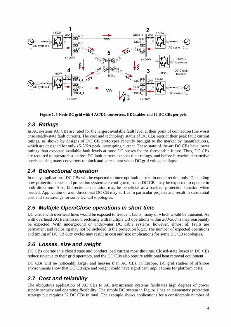
Figure 1shows a single line diagram of a 5-node ±400 kV DC grid, which consists of 4 AC/DC bi-pole
converters rated 800 MVA, 2kA per pole interconnecting the DC grid (busses 1-4) with corresponding
AC systems, one DC bus without a converter (node 5), 8 DC cables and 16 DC CBs per pole (32 DC CBs
in total). The grid topology has been selected as an illustrative example that provides reasonable power
transfer security while trying to limit the number of DC CBs. In comparable AC systems, considering
modern grid development practices, the number of AC CB would be much higher. The indicated power
and voltage levels are in the highest range of demonstrated DC CB technology.
For example, a short circuit fault occurring on line 3-4 would insert a low impedance at the point of fault
and result in high currents flowing into the fault from all parts of the network (as indicated by red
arrows). Depending on the impedances of the grid cables and of the severity of the fault itself, the fault
currents would have different magnitudes, but they can easily reach 10-30 times the rated current (say 20-
60 kA) at some points. These are destructive currents which grid components cannot withstand.
All high-power AC/DC converters have self-protection control logic, which blocks and disconnects
converters in the event of disturbances. Typically, self-protection thresholds are set at approximately 2 pu
current and 0.8 pu DC voltage, which for the considered system implies 4 kA current and a 320 kV
voltage.
In conventional AC transmission systems, generators have numerous self-protection controls, but the
thresholds are significantly higher relative to the nameplate rated variables. The line/cable impedances
also have much higher values in AC than DC systems because the frequency, f, contributes to the
reactance (the imaginary part of the impedance, 2πfL, where L is the inductance).
These factors lead to the conclusion that in a DC system CBs (and protection system) must respond much
faster than in AC systems, in order to prevent widespread loss in capacity (converter blocking) and
destructive fault current magnitudes.
2.2 Operating speed In a DC fault situation, current rises, and voltage falls throughout the DC grid during the delays
associated with DC protection and DC CB operation. Once the DC CBs open and isolate the DC fault, the
DC voltage recovers and DC power flows over the reconfigured grid at a newly established balance
operating point, which depends on the number of remaining operating converters and their control
strategies. The faster the DC CBs operate, the less the DC fault adversely affects the DC grid.
However, the blocking of nearby converters cannot be completely avoided even with application of the
fastest available DC CBs. This is because the converters closest to the fault point may experience high
current and thus block prior to the DC CBs opening. The most recent DC grid studies indicate that
temporary converter blocking for 10-30 ms is possible until the DC fault is cleared and the converters can
then be de-blocked to resume normal operation. The need for blocking converters will depend on the grid
topology and the fault location.
Many studies indicate that DC grids of various sizes and topologies can recover from any DC line fault if
the total protection time (DC CB opening time plus protection operation time) is within
approximaely10ms. This assumes that some converters may block by self-protection temporarily or
permanently, depending on the grid topology and the strategy used for protecting the network. Permanent
blocking after fault clearing occurs if the converter becomes isolated, and results in loss of grid capacity.
4
Figure 1. 5-Node DC grid with 4 AC/DC converters, 8 DCcables and 16 DC CBs per pole.
2.3 Ratings In AC systems AC CBs are rated for the largest available fault level at their point of connection (the worst
case steady-state fault current). The cost and technology status of DC CBs restrict their peak fault current
ratings, as shown by designs of DC CB prototypes recently brought to the market by manufacturers,
which are designed for only 15-20kA peak interrupting current. These state-of-the-art DC CBs have lower
ratings than expected available fault levels at most DC busses for the foreseeable future. Thus, DC CBs
are required to operate fast, before DC fault current exceeds their ratings, and before it reaches destructive
levels causing many converters to block and a resultant wider DC grid voltage collapse.
2.4 Bidirectional operation In many applications, DC CBs will be expected to interrupt fault current in one direction only. Depending
how protection zones and protection system are configured, some DC CBs may be expected to operate in
both directions. Also, bidirectional operation may be beneficial as a back-up protection function when
needed. Application of a unidirectional DC CB may suffice in particular projects and result in substantial
cost and size savings for some DC CB topologies.
2.5 Multiple Open/Close operations in short time DC Grids with overhead lines would be exposed to frequent faults, many of which would be transient. As
with overhead AC transmission, reclosing with multiple CB operations within 200-500ms may reasonably
be expected. With underground or underwater DC cable systems, however, almost all faults are
permanent and reclosing may not be included in the protection logic. The number of expected operations
and timing of DC CB duty cycles may result in cost and size implications for some DC CB topologies.
2.6 Losses, size and weight DC CBs operate in a closed state and conduct load current most the time. Closed-state losses in DC CBs
reduce revenue to their grid operators, and the DC CBs also require additional heat removal equipment.
DC CBs will be noticeably larger and heavier than AC CBs. In Europe, DC grid studies of offshore
environments show that DC CB size and weight could have significant implications for platform costs.
2.7 Cost and reliability The ubiquitous application of AC CBs to AC transmission systems facilitates high degrees of power
supply security and operating flexibility. The simple DC system in Figure 1 has an elementary protection
strategy but requires 32 DC CBs in total. The example shows applications for a considerable number of
5
DC CBs in future grids would be anticipated. DC CB costs will be higher than AC CBs, and for some DC
CB topologies perhaps substantially higher than AC CB costs.
The internal complexity of DC CBs requires further study of their failure modes to fully understand their
reliability considering that operational experience is minimal. . Some DC CBs using semiconductor
technologies have self-protection as discussed below, which needs to be considered by grid planners and
protection system developers.
2.8 Standardisation of inputs/outputs In large DC grids, the protection system will consist of multiple relays (microcontroller-based), which are
interconnected and use adjusted settings controlled by the grid operator. Grid topology changes and
expandability must be considered as important factors developing protection logic. Achieving desired
relay commands with components made by different vendors requires standardization of interconnections
and interoperability as important DC CB requirements.
3 Challenges with DC circuit opening
3.1 DC current commutation The first developers of DC systems learned that interrupting DC current is difficult. Trying to separate CB
contacts under a current flow creates an arc, which for high voltage systems is self-sustaining and
generates large amounts of heat caused by the arc resistance. With AC currents, there is a natural current
zero crossing twice every cycle (every 10 ms in 50 Hz systems). This momentary current interruption,
with the aid of engineering devices that ensure sufficient contact separation and an arc extinguishing
chamber, enables modern AC CBs to reliably interrupt very large currents within 20-60 ms.
There are no natural current zero crossings in DC systems. At low voltages of 10-30 V (automotive
applications) the arc voltage is larger than the system voltage and this reduces the current to zero. At
higher voltages there are two principal methods to interrupt DC current:
1) Use power electronics to commutate current into a parallel circuit. Semiconductors provide solid
insulation, and can interrupt large currents very quickly and without arcing. The principal
challenges are large component costs and high loses during normal closed-state operation.
2) Using additional circuits, such as commonly used LC resonant systems, to create current zero-
crossings in mechanical switches. Mechanical switches have practically negligible closed-state
losses and generally have low weigh, size, and cost at high voltage ratings. The foremost
challenge is arcing, which implies heavier and more complex contacts necessary for successful
operation that in turn leads to slower opening speeds.
Both methods are viable and have been demonstrated on high voltage and large current DC CB units.
3.2 DC current reduction and dissipation of energy The energy dissipation in a device is the product of the current and voltage across the device, multiplied
by time. With AC CBs there is minimal dissipation of energy because the contacts open when the load
current crosses zero. Any energy in the system is conveniently dissipated in the arc chamber.
With DC CBs, the moment of interruption occurs for a large value of DC load current that is reduced for
interruption by inserting a larger counter DC voltage, usually by the means of non-linear resistors (surge
arresters). An integral part of all DC CBs, these resistors are also called energy absorbers because they
need to absorb the energy from the line inductances and thus experience high voltage and high current for
a short period until the DC current is brought to zero. The expected energy dissipation at a 400 kV DC
voltage level is on the order of 10-100 MJ that affects the thermal ratings and time constants of the
absorbers, which is especially important if repeated DC CB operations are required. This degree of energy
dissipation also influences the DC CB cost, size, and weight.
6
3.3 Series inductor with DC Circuit Breakers Each DC CB in HVDC grids requires use of a series inductor on the order of 50-300 mH. Although this
inductor cannot reduce the amplitude of the DC fault current, it can limit the rate or rise of the fault
current. Sized for a given protection and DC CB operating times, this inductor limits the peak fault
current that is experienced by DC CBs and other components in the DC grid. For example, a 400 kV DC
bus with a desired interrupt time (DC CB opening and protection time) of 4 ms and with a maximum peak
interrupting current of 16 kA requires inductor of around 100mH.
Installation of series inductors with DC CBs also facilitate DC grid protection system selectivity, i.e. they
enable the protection system to differentiate between faults in inner and outer protective zones.
Because of these multiple requirements for the series inductor, it is not clear if the series inductor will be
considered as part of future DC CB units, or if it will be regarded as a part of the DC protection system.
On the negative side, series inductors store energy and negatively influence voltage control of DC grids.
In addition, the energy stored in the inductor must be dissipated by DC CBs in the event of fault
interruption.
4 Main DC CB topologies Several manufacturers have invested substantially in further developing DC CBs to high technology
readiness levels. These manufacturers have reported results from laboratory tests of DC CB prototypes in
the range of 40-80 kV with peak fault current interruption capabilities of approximately 15-20 kA. Plans
call for these units to become standard modules through series connections to achieve higher DC voltage
levels. The communications from manufacturers and data from recent installations indicate that there are
no substantial obstacles to implement 300-400 kV DC CBs.
The European Union has directed substantial resources towards understanding DC CBs, including tests of
several full-scale (70-80 kV) DC CBs at an independent laboratory. There is joint effort by multiple
manufacturers, grid operators, academia, and consultants substantially contributes towards acceptance of
DC CBs by advancing the understanding of their control, operating limits, testing, failure modes, and
interactions with DC grid components. Considerable further effort is being directed toward achieving
interoperability among various DC CB technologies and different manufacturers, and to initiate
standardisation.
Many different DC CB topologies discussed in research papers have been proposed, with some prototypes
of varying ratings undergoing field tests. Many new patents related to DC CBs have emerged recently,
and intensive research will continue in this field.
It is possible to group most DC CB designs into two main families: 1) mechanical DC CBs and 2) hybrid
DC CBs using semiconductor valves. The typical designs from each family will be presented below for
illustration purposes, without reference to any particular manufacturer.
5 Mechanical DC Circuit Breaker
5.1 Topology Figure 2 shows a typical topology of a mechanical HVDC circuit breaker. It consists of the following:
1) Main branch consisting of a breaker which is able to sustain arcing. Commonly this is an AC VI
(Vacuum Interrupter) with an enhanced driving mechanism to reduce opening time.
2) Current injection branches with pre-charged capacitors. Two branches are shown, which enable
two operations in a short period of time, considering that capacitor charging may take a long
time. The second branch is not needed if the required breaker duty cycle consists of only a single
opening. Switches VI3a and VI3b are similar to VI1. The natural resonant frequency of the LC
circuit can be increased to practical values approximating 2-3 kHz that would reduce the required
sizes of L1 and C1. The resistors R1 are required for capacitor charging.
3) Energy absorber which consists of banks of surge arresters. These arresters are based on standard
surge arresters widely used in AC systems for overvoltage protection.

7
4) Residual breaker, VI2, which interrupts only a small current, and where opening speed is not
critical.
5) Ldc is a current limiting inductor that reduces the rate of rise of fault current.
The mechanical DC CB presented is also called a current injection DC CB, since it employs pre-charged
capacitors, C1a and C1b, which substantially improve the speed of each operation.
Figure 2. Mechanical DC Circuit Breaker.
5.2 Operating principles Figure 3 illustrates interruption of 15kA peak DC fault current with a mechanical DC CB on a 400 kV DC
system, assuming a DC fault at t=0s. A series inductor of Ldc=240 mH is used. Figure 3A shows that it
takes approximately 8 ms for the VI1 contacts to fully separate, and at this instant VI3 closes, injecting an
oscillating current, IS3 that facilitates a zero crossing of IVI1. When the arc is interrupted in VI1, the DC
current IDC is transferred to the energy absorber and voltage VDCCB abruptly rises to the clipping voltage
of the surge arresters, which is commonly around 1.5 pu (600 kV). This high voltage brings a negative
voltage across inductor Ldc (400 kV-600 kV), enabling fault current suppression. The fault current is fully
extinguished after an additional 20 ms, as seen in Figure 3B.
Commonly, manufacturers will specify the time to voltage recovery (8 ms in Figure 3) as the key DC CB
performance indicator. The peak fault current is specified as the single indicator of interrupting capability
(15 kA in 0), which is a key parameter for sizing the series inductor Ldc, which could also vary for
different DC CB technologies because of different opening speeds.
The expected energy dissipation by the arrestors in this case is around ESA=83MJ, as seen in 0D. Figure 3
illustrates fault current interruption in the positive direction, but this DC CB topology can similarly
interrupt DC fault current in the negative direction. However, since the charge of capacitor C1 is unipolar,
the responses in the negative direction will be slightly different and component stresses might be higher.

8
Figure 3 DC fault current interruption with 400kV, 16kA, 8ms Mechanical DC Circuit Breaker.
6 Hybrid DC Circuit Breaker
6.1 Topology A representative topology for hybrid DC CB is shown in Figure 4. It consists of the following:
1) A Main Branch with two 400kV semiconductor valves T2A and T2B (one for each direction). If
protection in only one direction is desired, then only one valve would be required. Each valve is
similar to one arm of a (6-arm) VSC HVDC converter. This branch can conduct load current in a
closed state, but losses would be high with prolonged operation.
2) The auxiliary branch, which has low resistance, conducts full load current in closed state. This
branch includes:
a. A low-voltage semiconductor valve T1. This valve is also called the load commutation
switch, and it should have a voltage rating comparable with the closed-state voltage drop
of the valve T2 (i.e. in the order of 10kV).
b. An ultrafast disconnect switch S1. This switch cannot support arcing (it can open only at
zero current), but has an extremely fast opening speed. Significant technological
advances have been made recently using Thomson coil drivers, and the opening speed for
320kV units has been demonstrated as approximately 2ms.
3) Energy absorber, SA, which consists of banks of surge arresters.
4) Residual breaker S2 which interrupts only the arrester leakage current. Its opening speed is not
critical.
Ldc is a current limiting inductor.

9
Figure 4 Hybrid DC Circuit Breaker.
The low voltage valve T1 continuously conducts load current, and it must withstand fault current in the
period before the protection relay sends the trip signal. In practice, this valve consists of several parallel
branches, with each branch having a few IGBTs (Insulated Gate Bipolar Transistors) in series. Because of
the continuous conduction stress, this valve requires a forced liquid cooling system. The main valve T2
only conducts the fault current for around 2ms and therefore it does not need liquid cooling. However, the
whole hybrid DC CB should be located indoors (in a valve hall) similar to any large converter.
6.2 Operating principles Figure 5 illustrates a DC fault on a 400 kV DC system interrupted by a hybrid DC CB that uses a series
inductor of Ldc=76 mH. The fault occurs at t=0s and the current peaks at 15 kA Figure 5B shows that S1
begins to open when the current is transferred to T2 and IT1 drops to zero. It takes 2ms for S1 to fully open
while T2 is conducting. Once S1 is open, the current is commutated to the energy absorber by opening T2.
As current commutates to surge arresters, their voltage rises to 1.5 pu, which initiates current suppression.
It takes another 5 ms for the fault current to reduce to zero, as seen in Figure 5A. Figure 5D illustrates
that the expected total energy dissipation in this case is ESA is equal to 21 MJ.

10
Figure 5. DC fault current interruption with 400kV, 16kA, 8ms Hybrid DC CB.
6.3 Self protection Similar to all high-power converters, the semiconductor valves in hybrid DC CBs have self-protection
that opens the valves in the event of excessive current. Although unlikely, a failure in some grid
protection components (relay, sensor, communication, etc.) could fail to send a trip signal to the DC CB
in a DC fault situation, which results in rising high DC CB current without a DC CB trip command. In
practical terms this means that the DC CB may open on its own to protect itself at some DC current
threshold (which is much higher than DC grid protection settings).
This function will have a largely positive connotation. If the DC grid protection were to fail for whatever
reason, it can be expected that the hybrid DC CB would open at its self-protection threshold as the last
line of defense.
6.4 Fault current limiting Hybrid DC CBs can also act as DC fault current limiters. By employing ON/OFF control of the individual
modules in the valve T2, the number of inserted arresters can be varied, which can regulate current. This
operating mode is limited by the thermal capability of energy absorbers, and can most likely be achieved
for only short periods of time.
This fault limiting operating mode can be beneficial in some applications, for example:
1. Limiting fault currents allows additional response time for fault clearing by other DC CBs
installed on other lines in a DC grid. In practical terms, the DC CBs or protection systems on the
other lines may have slower response times.
2. Limiting inrush currents when connecting DC lines eliminates the need for pre-insertion resistors
on the DC CBs.
11
7 DC Circuit Breakers Installed in China
7.1 Installed hybrid DC CB in the Zhoushan multiterminal system Among the islands of the Zhoushan archipelago, the largest power-consuming islands include the main
island of Zhoushan, followed by the islands of Daishan, Qushan, Yangshan, and Sijiao. The annual load
of the Zhoushan power grid reached 780 MW in 2010, and is estimated to reach 2000 MW in 2020 as a
result of higher demand arising from economic development.
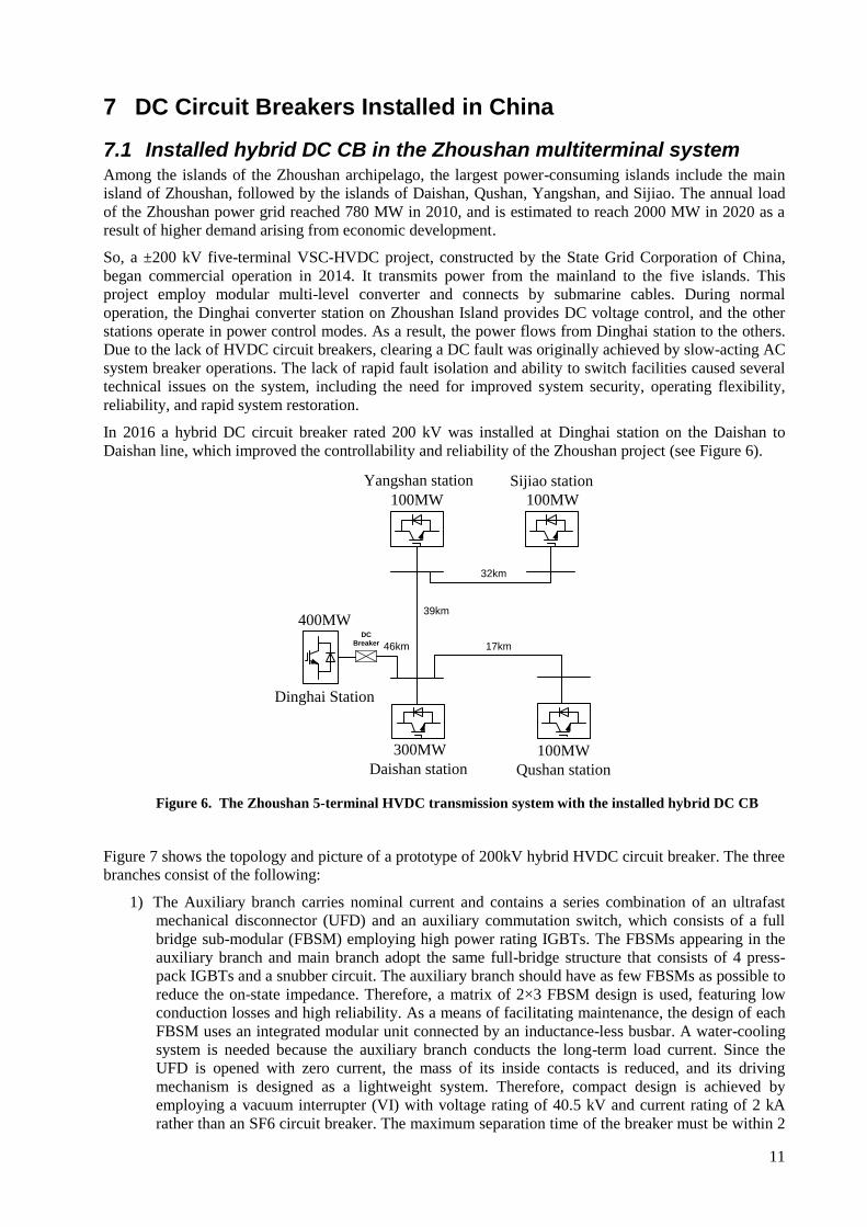
So, a ±200 kV five-terminal VSC-HVDC project, constructed by the State Grid Corporation of China,
began commercial operation in 2014. It transmits power from the mainland to the five islands. This
project employ modular multi-level converter and connects by submarine cables. During normal
operation, the Dinghai converter station on Zhoushan Island provides DC voltage control, and the other
stations operate in power control modes. As a result, the power flows from Dinghai station to the others.
Due to the lack of HVDC circuit breakers, clearing a DC fault was originally achieved by slow-acting AC
system breaker operations. The lack of rapid fault isolation and ability to switch facilities caused several
technical issues on the system, including the need for improved system security, operating flexibility,
reliability, and rapid system restoration.
In 2016 a hybrid DC circuit breaker rated 200 kV was installed at Dinghai station on the Daishan to
Daishan line, which improved the controllability and reliability of the Zhoushan project (see Figure 6).
400MW
300MW
100MW 100MW
100MW
Qushan station
Dinghai Station
Yangshan station Sijiao station
Daishan station
32km
17km
39km
46km
DC
Breaker
Figure 6. The Zhoushan 5-terminal HVDC transmission system with the installed hybrid DC CB
Figure 7 shows the topology and picture of a prototype of 200kV hybrid HVDC circuit breaker. The three
branches consist of the following:
1) The Auxiliary branch carries nominal current and contains a series combination of an ultrafast
mechanical disconnector (UFD) and an auxiliary commutation switch, which consists of a full
bridge sub-modular (FBSM) employing high power rating IGBTs. The FBSMs appearing in the
auxiliary branch and main branch adopt the same full-bridge structure that consists of 4 press-
pack IGBTs and a snubber circuit. The auxiliary branch should have as few FBSMs as possible to
reduce the on-state impedance. Therefore, a matrix of 2×3 FBSM design is used, featuring low
conduction losses and high reliability. As a means of facilitating maintenance, the design of each
FBSM uses an integrated modular unit connected by an inductance-less busbar. A water-cooling
system is needed because the auxiliary branch conducts the long-term load current. Since the
UFD is opened with zero current, the mass of its inside contacts is reduced, and its driving
mechanism is designed as a lightweight system. Therefore, compact design is achieved by
employing a vacuum interrupter (VI) with voltage rating of 40.5 kV and current rating of 2 kA
rather than an SF6 circuit breaker. The maximum separation time of the breaker must be within 2
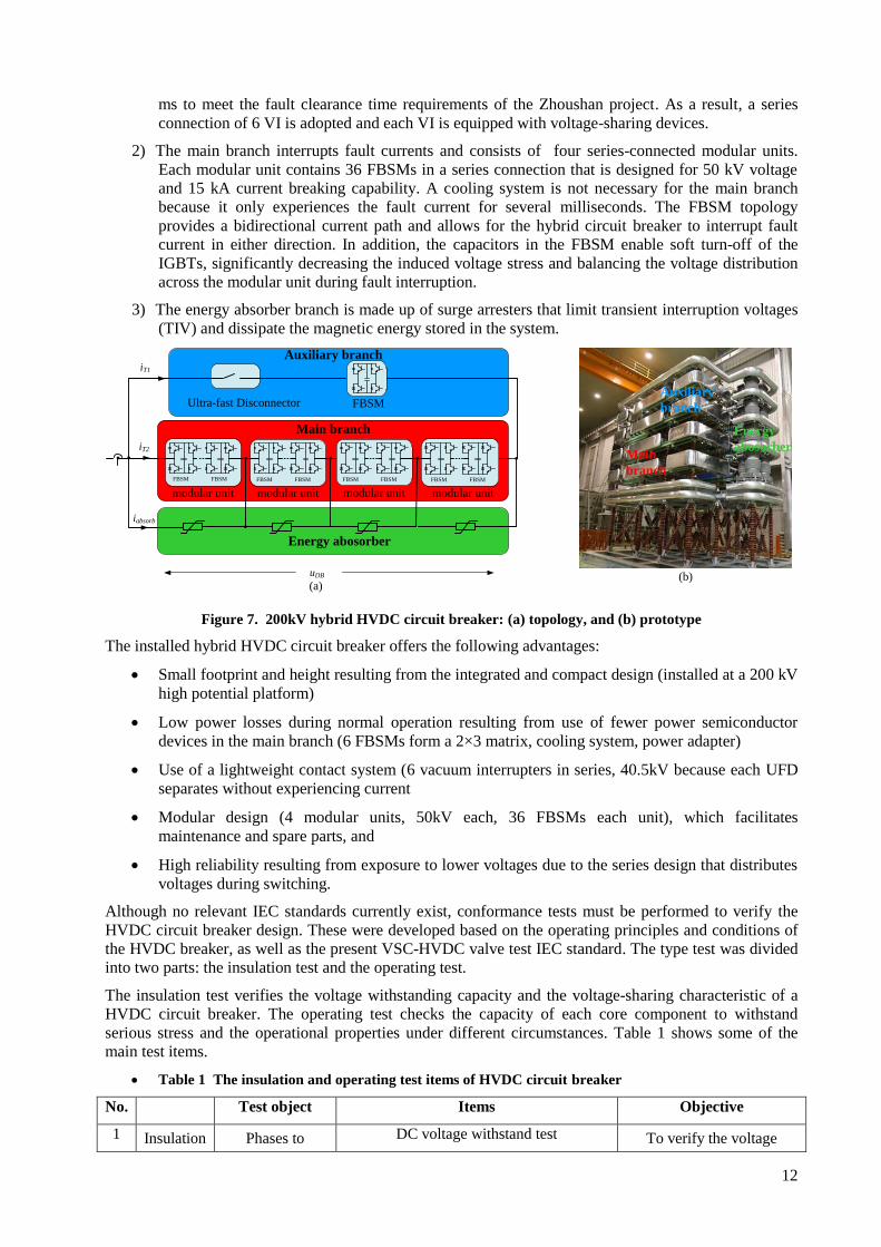
12
ms to meet the fault clearance time requirements of the Zhoushan project. As a result, a series
connection of 6 VI is adopted and each VI is equipped with voltage-sharing devices.
2) The main branch interrupts fault currents and consists of four series-connected modular units.
Each modular unit contains 36 FBSMs in a series connection that is designed for 50 kV voltage
and 15 kA current breaking capability. A cooling system is not necessary for the main branch
because it only experiences the fault current for several milliseconds. The FBSM topology
provides a bidirectional current path and allows for the hybrid circuit breaker to interrupt fault
current in either direction. In addition, the capacitors in the FBSM enable soft turn-off of the
IGBTs, significantly decreasing the induced voltage stress and balancing the voltage distribution
across the modular unit during fault interruption.
3) The energy absorber branch is made up of surge arresters that limit transient interruption voltages
(TIV) and dissipate the magnetic energy stored in the system.
Auxiliary branch
Main branch
Ultra-fast Disconnector FBSM
modular unit modular unit modular unit
iT1
iT2
iabsorb
uDB
Energy abosorber
FBSM FBSM FBSM FBSM FBSM FBSM
(a)(b)
Energy
abosorberMain
branch
Auxiliary
branch
modular unit
FBSM FBSM
Figure 7. 200kV hybrid HVDC circuit breaker: (a) topology, and (b) prototype
The installed hybrid HVDC circuit breaker offers the following advantages:
Small footprint and height resulting from the integrated and compact design (installed at a 200 kV
high potential platform)
Low power losses during normal operation resulting from use of fewer power semiconductor
devices in the main branch (6 FBSMs form a 2×3 matrix, cooling system, power adapter)
Use of a lightweight contact system (6 vacuum interrupters in series, 40.5kV because each UFD
separates without experiencing current
Modular design (4 modular units, 50kV each, 36 FBSMs each unit), which facilitates
maintenance and spare parts, and
High reliability resulting from exposure to lower voltages due to the series design that distributes
voltages during switching.
Although no relevant IEC standards currently exist, conformance tests must be performed to verify the
HVDC circuit breaker design. These were developed based on the operating principles and conditions of
the HVDC breaker, as well as the present VSC-HVDC valve test IEC standard. The type test was divided
into two parts: the insulation test and the operating test.
The insulation test verifies the voltage withstanding capacity and the voltage-sharing characteristic of a
HVDC circuit breaker. The operating test checks the capacity of each core component to withstand
serious stress and the operational properties under different circumstances. Table 1 shows some of the
main test items.
Table 1 The insulation and operating test items of HVDC circuit breaker
No. Test object Items Objective
1 Insulation Phases to DC voltage withstand test To verify the voltage
13
2 test ground Switching impulse withstand test (SWT) withstanding capacity and
partial discharge level of
support structure 3 Lighting impulse withstand test (LWT)
4 Across the open
contacts
DC voltage withstand test To verify the voltage
withstanding capacity of
across the open contacts 5 SWT
6
Operating
test
Key components
Peak withstand current test
To verify the current
withstanding capacitor of
the circuit breaker
7 Overload withstand current test
8 Short-time withstand current test
9 Short-time withstand current test
10
Overall
prototype
Rated current interruption test To verify the current
interruption capacity and
the interruption time of the
overall prototype and the
program correctness of the
control and protection
system
11 Short-circuit current interruption test
12 Rated current making test
13 Short-circuit making test
The 200kV hybrid DC circuit breaker successfully passed the test where a 15 kA short-circuit current was
cleared within 3ms and the transient interruption voltage across the test object exceeded 320kV.
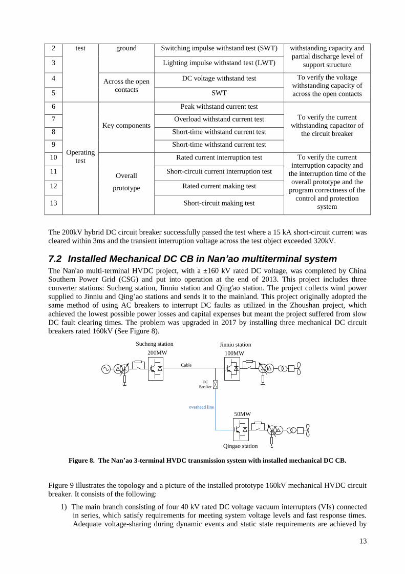
7.2 Installed Mechanical DC CB in Nan’ao multiterminal system The Nan'ao multi-terminal HVDC project, with a ±160 kV rated DC voltage, was completed by China
Southern Power Grid (CSG) and put into operation at the end of 2013. This project includes three
converter stations: Sucheng station, Jinniu station and Qing'ao station. The project collects wind power
supplied to Jinniu and Qing’ao stations and sends it to the mainland. This project originally adopted the
same method of using AC breakers to interrupt DC faults as utilized in the Zhoushan project, which
achieved the lowest possible power losses and capital expenses but meant the project suffered from slow
DC fault clearing times. The problem was upgraded in 2017 by installing three mechanical DC circuit
breakers rated 160kV (See Figure 8).
200MW
overhead line
Cable
100MW
50MW
DC
Breaker
Sucheng station Jinniu station
Qingao station
Figure 8. The Nan’ao 3-terminal HVDC transmission system with installed mechanical DC CB.
Figure 9 illustrates the topology and a picture of the installed prototype 160kV mechanical HVDC circuit
breaker. It consists of the following:
1) The main branch consisting of four 40 kV rated DC voltage vacuum interrupters (VIs) connected
in series, which satisfy requirements for meeting system voltage levels and fast response times.
Adequate voltage-sharing during dynamic events and static state requirements are achieved by
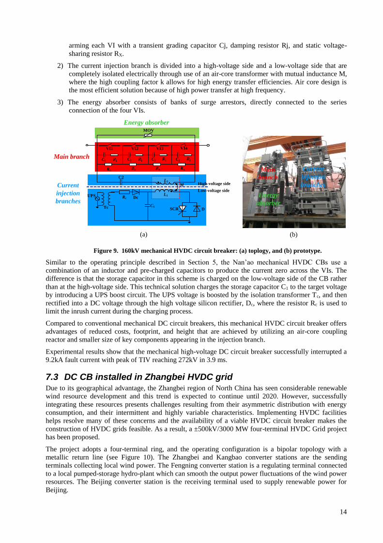
14
arming each VI with a transient grading capacitor Cj, damping resistor Rj, and static voltage-
sharing resistor RX.
2) The current injection branch is divided into a high-voltage side and a low-voltage side that are
completely isolated electrically through use of an air-core transformer with mutual inductance M,
where the high coupling factor k allows for high energy transfer efficiencies. Air core design is
the most efficient solution because of high power transfer at high frequency.
3) The energy absorber consists of banks of surge arrestors, directly connected to the series
connection of the four VIs.
VI1
Cj Rj
Rx
MOV
C1
C2
SCR
High-voltage side
Low-voltage side
L2
L1Rc Dc
Tc
M
VI2 VI3 VI4
UPS
D
Rx Rx Rx
Rj Rj RjCj Cj Cj
(a) (b)
Main branch
Current
injection
branches
Energy absorber
Main
branch
Current
injection
branches
Energy
absorber
Figure 9. 160kV mechanical HVDC circuit breaker: (a) toplogy, and (b) prototype.
Similar to the operating principle described in Section 5, the Nan’ao mechanical HVDC CBs use a
combination of an inductor and pre-charged capacitors to produce the current zero across the VIs. The
difference is that the storage capacitor in this scheme is charged on the low-voltage side of the CB rather
than at the high-voltage side. This technical solution charges the storage capacitor C1 to the target voltage
by introducing a UPS boost circuit. The UPS voltage is boosted by the isolation transformer Tc, and then
rectified into a DC voltage through the high voltage silicon rectifier, Dc, where the resistor Rc is used to
limit the inrush current during the charging process.
Compared to conventional mechanical DC circuit breakers, this mechanical HVDC circuit breaker offers
advantages of reduced costs, footprint, and height that are achieved by utilizing an air-core coupling
reactor and smaller size of key components appearing in the injection branch.
Experimental results show that the mechanical high-voltage DC circuit breaker successfully interrupted a
9.2kA fault current with peak of TIV reaching 272kV in 3.9 ms.
7.3 DC CB installed in Zhangbei HVDC grid Due to its geographical advantage, the Zhangbei region of North China has seen considerable renewable
wind resource development and this trend is expected to continue until 2020. However, successfully
integrating these resources presents challenges resulting from their asymmetric distribution with energy
consumption, and their intermittent and highly variable characteristics. Implementing HVDC facilities
helps resolve many of these concerns and the availability of a viable HVDC circuit breaker makes the
construction of HVDC grids feasible. As a result, a ±500kV/3000 MW four-terminal HVDC Grid project
has been proposed.
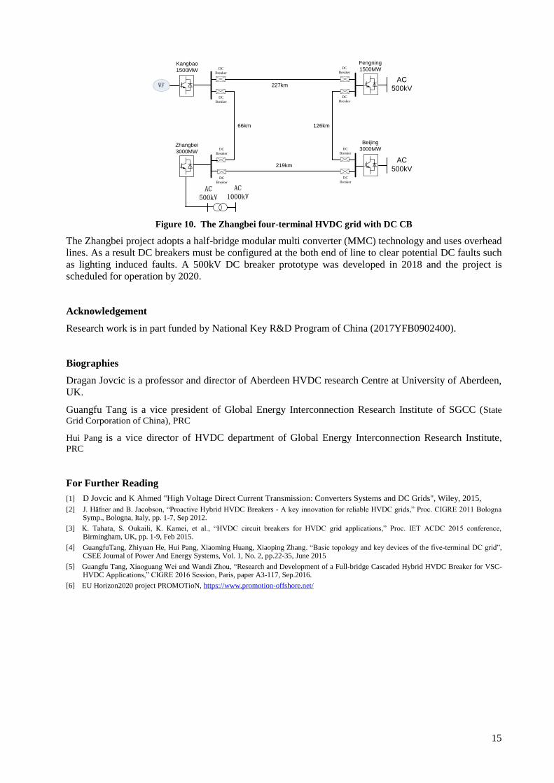
The project adopts a four-terminal ring, and the operating configuration is a bipolar topology with a
metallic return line (see Figure 10). The Zhangbei and Kangbao converter stations are the sending
terminals collecting local wind power. The Fengning converter station is a regulating terminal connected
to a local pumped-storage hydro-plant which can smooth the output power fluctuations of the wind power
resources. The Beijing converter station is the receiving terminal used to supply renewable power for
Beijing.
15
WF
Kangbao
1500MW
Zhangbei
3000MW
Fengning
1500MW
AC 500kV
AC
500kV
227km
219km
66km 126km
AC
500kV
Beijing
3000MW
AC 1000kV
DC
Breaker
DC
Breaker
DC
Breaker
DC
Breaker
DC
Breaker
DC
Breaker
DC
Breaker
DC
Breaker
Figure 10. The Zhangbei four-terminal HVDC grid with DC CB
The Zhangbei project adopts a half-bridge modular multi converter (MMC) technology and uses overhead
lines. As a result DC breakers must be configured at the both end of line to clear potential DC faults such
as lighting induced faults. A 500kV DC breaker prototype was developed in 2018 and the project is
scheduled for operation by 2020.
Acknowledgement
Research work is in part funded by National Key R&D Program of China (2017YFB0902400).
Biographies
Dragan Jovcic is a professor and director of Aberdeen HVDC research Centre at University of Aberdeen,
UK.
Guangfu Tang is a vice president of Global Energy Interconnection Research Institute of SGCC (State
Grid Corporation of China), PRC
Hui Pang is a vice director of HVDC department of Global Energy Interconnection Research Institute,
PRC
For Further Reading
[1] D Jovcic and K Ahmed "High Voltage Direct Current Transmission: Converters Systems and DC Grids", Wiley, 2015,
[2] J. Häfner and B. Jacobson, “Proactive Hybrid HVDC Breakers - A key innovation for reliable HVDC grids,” Proc. CIGRE 2011 Bologna Symp., Bologna, Italy, pp. 1-7, Sep 2012.
[3] K. Tahata, S. Oukaili, K. Kamei, et al., “HVDC circuit breakers for HVDC grid applications,” Proc. IET ACDC 2015 conference, Birmingham, UK, pp. 1-9, Feb 2015.
[4] GuangfuTang, Zhiyuan He, Hui Pang, Xiaoming Huang, Xiaoping Zhang. “Basic topology and key devices of the five-terminal DC grid”, CSEE Journal of Power And Energy Systems, Vol. 1, No. 2, pp.22-35, June 2015
[5] Guangfu Tang, Xiaoguang Wei and Wandi Zhou, “Research and Development of a Full-bridge Cascaded Hybrid HVDC Breaker for VSC-HVDC Applications,” CIGRE 2016 Session, Paris, paper A3-117, Sep.2016.
[6] EU Horizon2020 project PROMOTioN, https://www.promotion-offshore.net/