Embed Size (px)
Citation preview
~ 1 ~ Signature of Bidder
ADMINISTRATOR
WESCO UTILITY *************************************************
TENDER SPECIFICATION FOR
CONSTRUCTION OF NEW 33 KV BAY WITH
INSTALLATION OF ALL REQUIRED
EQUIPMENTS & METERING ARRANGEMENT IN
EXISTING 33/11 KV ODSSP PRIMARY SUB-
STATION, DARLIPALI, KARAMDIHI,
BALISHANKARA, DALPOSH, JAREIKELA,
DHULUNDA, LAKANPUR
for
POWER SUPPLY TO MEGA LIFT PROJECT
TENDER NOTICE No.: WESCO/WORKS/18-19/04 Date:
04.11.2018
Semi Turnkey Contract (Supply & Erection)
1) DATE OF OPENING OF TENDER : 26.11.2018
2) TIME : 16:00 hrs.
3) PLACE : WESCO Utility Head Quarter Office
(EAST Block), Burla
~ 2 ~ Signature of Bidder
WESCO UTILITY
Headquarter: At/PO: Burla, Dist: Sambalpur - 768017, Odisha
Phone: (0663)2431297, Facsimile: (0663) 2432115
E-Mail: [email protected], Web site: www.wescoorissa.com
DEPARTMENT OF WORKS & PLANNING
Head Quarter Office (EAST BUILDING), Burla-768017
E-Mail: [email protected] ***************************************************************************************
TENDER NOTICE NO: WESCO/WORKS/18-19/04 Date: 04.11.2018
Work Description: CONSTRUCTION OF 33 KV NEW BAY WITH INSTALLATION
OF EQUIPMENTS IN EXISTING 33/11 KV ODSSP PRIMARY
SUB-STATION, DARLIPALI, KARAMDIHI, BALISHANKARA,
DALPOSH, JAREIKELA, DHULUNDA, LAKANPUR FOR
POWER SUPPLY TO MEGA LIFT PROJECT
CONTENTS
SECTION NO. DESCRIPTION PAGE NO.
SECTION: I INVITATION FOR BIDS (IFB) 5-9
SECTION: II GENERAL TERMS AND CONDITIONS OF CONTRACT (GTCC) 10-25
SECTION: III TECHNICAL SPECIFICATION 26-84
SECTION: IV LIST OF ANNEXURES (SCHEDULES & FORMATS) 85-113
~ 3 ~ Signature of Bidder
WESCO UTILITY
Headquarter: At/PO: Burla, Dist: Sambalpur - 768017, Odisha
Phone: (0663)2431297, Facsimile: (0663) 2432115
E-Mail: [email protected], Web site: www.wescoorissa.com
DEPARTMENT OF WORKS & PLANNING
Head Quarter Office (EAST Building), Burla-768017
E-Mail: worksandplanning @wescoorissa.com ***************************************************************************************
TENDER NOTICE NO: WESCO/WORKS/18-19/04 Date: 04.11.2018
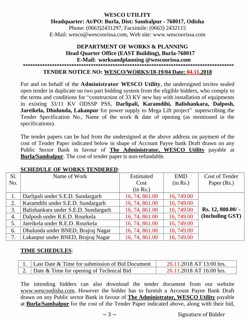
For and on behalf of the Administrator WESCO Utility, the undersigned invites sealed
open tender in duplicate on two part bidding system from the eligible bidders, who comply to
the terms and conditions for “construction of 33 KV new bay with installation of equipments
in existing 33/11 KV ODSSP PSS, Darlipali, Karamdihi, Balishankara, Dalposh,
Jareikela, Dhulunda, Lakanpur for power supply to Mega Lift project” superscribing the
Tender Specification No., Name of the work & date of opening (as mentioned in the
specifications).
The tender papers can be had from the undersigned at the above address on payment of the
cost of Tender Paper indicated below in shape of Account Payee bank Draft drawn on any
Public Sector Bank in favour of The Administrator, WESCO Utility payable at
Burla/Sambalpur. The cost of tender paper is non-refundable.
SCHEDULE OF WORKS TENDERED:
Sl.
No.
Name of Work Estimated
Cost
(in Rs.)
EMD
(in Rs.)
Cost of Tender
Paper (Rs.)
1. Darlipali under S.E.D. Sundargarh 16, 74, 861.00 16, 749.00
Rs. 12, 800.00/ -
(Including GST)
2. Karamdihi under S.E.D. Sundargarh 16, 74, 861.00 16, 749.00
3. Balishankara under S.E.D. Sundargarh 16, 74, 861.00 16, 749.00
4. Dalposh under R.E.D. Rourkela 16, 74, 861.00 16, 749.00
5. Jareikela under R.E.D. Rourkela 16, 74, 861.00 16, 749.00
6. Dhulunda under BNED, Brajraj Nagar 16, 74, 861.00 16, 749.00
7. Lakanpur under BNED, Brajraj Nagar 16, 74, 861.00 16, 749.00
TIME SCHEDULES:
1. Last Date & Time for submission of Bid Document 26.11.2018 AT 13:00 hrs.
2. Date & Time for opening of Technical Bid 26.11.2018 AT 16:00 hrs.
The intending bidders can also download the tender document from our website
www.wescoodisha.com. However the bidder has to furnish a Account Payee Bank Draft
drawn on any Public sector Bank in favour of The Administrator, WESCO Utility payable
at Burla/Sambalpur for the cost of the Tender Paper indicated above, along with their bid,
~ 4 ~ Signature of Bidder
failing of which the bid will be rejected outright. In the event of any specified date for the
sale, submission or opening of bids being declared as holiday for WESCO Utility, the bids
will be sold / received / opened up at the appointed time on the next working day.
WESCO Utility also reserves the right to accept or reject any or all tenders without
assigning any reason thereof, if the situation so warrants.
For detail Tender Specification & Terms and Conditions, please visit our website
www.wescoodisha.com.
(sd/-)
GM (Works)
~ 5 ~ Signature of Bidder
SECTION – I
INVITATION FOR BIDS (IFB)
~ 6 ~ Signature of Bidder
WESCO UTILITY
Headquarter: At/PO: Burla, Dist: Sambalpur - 768017, Odisha
Phone: (0663)2431297, Facsimile: (0663) 2432115
E-Mail: [email protected], Web site: www.wescoorissa.com
DEPARTMENT OF WORKS & PLANNING
Head Quarter Office (EAST Building), Burla-768017
E-Mail: [email protected] ***************************************************************************************
TENDER NOTICE NO: WESCO/WORKS/18-19/04 Date: 04.11.2018
INVITATION FOR BIDS (IFB)
for
“Construction of 33 KV new bay with installation of
equipments in existing 33/11 KV ODSSP PSS,
Darlipali, Karamdihi, Balishankara, Dalposh,
Jareikela, Dhulunda, Lakanpur for power supply to
Mega Lift project”
(COMPETITIVE BIDDING)
TENDER NOTICE NO: WESCO/WORKS/18-19/04 Date: 04.11.2018
SECTION – I
1.0 For and on behalf of the WESCO Utility, the undersigned invites bid under two part
bidding system in sealed cover in duplicate duly superscribed with tender Notice
No.: _______, and Date of Opening: _______ from the reputed licensed firms/
individuals having valid HT Electrical License for carrying out “Construction of 33
KV new bay with installation of equipments in existing 33/11 KV ODSSP PSS,
Darlipali, Karamdihi, Balishankara, Dalposh, Jareikela, Dhulunda, Lakanpur for
power supply to Mega Lift project”.
2.0 Submission of the Bids:
2.1 The Bidders are required to submit a detailed and comprehensive bid, consisting of
Technical and Commercial Proposal and conditions / schedule of non-compliance,
if any.
2.2 The submission of the Bids shall be in the manner specified in the instruction to
Bidders. The due date of submission shall be 26.11.2018 up-to 13:00 hrs.
3.0 WESCO Utility will not be responsible for any costs or expenses incurred by bidders
in connection with the preparation and delivery of bids.

~ 7 ~ Signature of Bidder
3.1 WESCO Utility reserves the right to cancel, postpone, withdraw the invitation for Bids
without assigning any reason thereof and shall bear no liability whatsoever consequent
upon such a decision if the situation so warrants.
4.0 E.M.D & TIME SCHEDULES:
Description Date
Last Date for Submission
of Tenders
26.11.2018 up to 13.00 hrs.
Opening of Technical Bid 26.11.2018 up to 16.00 hrs.
Cost of Tender
Paper
(Non Refundable)
Rs. 12, 800.00 (Rupees Twelve Thousand Eight Hundred
only) including GST in shape of Account Payee demand
draft issued in favour of The Administrator, WESCO
Utility payable at Burla/Sambalpur
Amount of
E.M.D. Payable
As mentioned Packages in Tender Notice in shape of account
payee demand draft / Bank Guarantee in favour of The
Administrator, WESCO Utility payable at
Burla/Sambalpur. In case of Bank Guarantee, the Bank
Guarantee must be encashable at Burla/ Sambalpur
5.0 SCHEDULE OF REQUIREMENTS:
Bidder must have to quote for the entire quantum of works specified in the tender
schedule specified under each such package(s).
6.0 QUALIFICATION OF BIDDERS:
6.1 Financial Criteria for qualification:
The HT Electrical Contractor should be having the average Annual turnover (the
average of Best three financial years out of the last five financial years ending 31st
March of previous year) not less than 50% of the estimated value of all the
package(s) quoted by the bidder(s) in the Electrification works. In case the Bidder is in
existence for less than three financial years, the average annual turnover shall be sum of
turnover in the completed no. of financial years divided by no. of years for which the
bidder is in existence for the purpose of meeting the above criteria. Turnover of the
entity only (excluding its sister concerns) shall be considered for arriving at Annual
Turnover.
6.2 Technical Criteria for qualification:
6.2.1 “The bidder must have executed construction of 1 no. 33 KV VCB Installation or
above capacity during the last five financial years preceding to the year of tender
notification and should have successful operation of minimum period of one year.
Bidder must enclose copies of the relevant work orders along with client certified
copies of Performance Certificates.
6.2.2 If the bidder(s) participate in multiple packages, the qualifying requirement for work
experience shall be considered / evaluated independently/separately for each package.
However, the qualifying requirement for Turn Over shall be added together to qualify

~ 8 ~ Signature of Bidder
the Turnover requirement for each package(s).
7.0 WESCO Utility reserves the right to waive minor deviation, if they do not materially
affect the capacity of the bidder to perform the contract.
8.0 WORK COMPLETION PERIOD:
Work completion period for the complete of each project: 60 Days
9.0 Bid documents can be downloaded from the website namely: wescoodisha.com. The bid
documents filled in all respects should be accompanied with the following documents in
a sealed cover envelops clearly “Super scribing, Tender Call Notice No., Name of the
package, Dtd. of opening”.
10.0 The cost of Tender Paper as indicated above should be deposited in shape of Bank Draft
drawn on any scheduled Bank in favour of Administrator WESCO Utility payable at
Burla/Sambalpur.
11.0 The E.M.D. as mentioned above should be deposited in shape of Bank Draft drawn on
any scheduled Bank in favour of Administrator WESCO Utility payable at Burla /
Sambalpur. The E.M.D. of unsuccessful tenderers will be refunded soon after
finalization of the tender.
12.0 Bid documents will be received at WESCO Utility, Works & Planning Department,
Head Quarter Office, Burla, Dist: Sambalpur on or before 26.11.2018 at 13.00 hrs. The
“Technical and commercial bid” will be opened on 26.11.2018 at 16.00 hrs. in the
presence of the bidders/ or his authorized representatives.
13.0 The Date & time for opening of “Price Bid” will be intimated latter on. The price bid of
bidders who are successfully qualified on “Techno-Commercial” evaluation shall only
be opened. The price bid shall be opened in presence of the bidders/ or his authorized
representatives.
14.0 Bidders are required to quote the rates in words and figures and put their signatures
below every page and also sign every corrections made in the bid documents. No over-
writing will be entertained.
15.0 The intending tenderers / applicants may verify the scope of the work from the Office of
the Concern Executive Engineer or Works and Planning Department, WESCO, Burla in
any working day between 10:00 AM to 05:00 PM. The last date of receipt of
tender/application by the Works and Planning Department, WESCO, Burla, is on Dt.
26.11.2018 up to 13:00 Hour and tender received beyond the stipulated period will
not be taken into consideration.
16.0 In the event of any specified date for the sale, submission or opening of bids being
declared as holiday. The bids will be sold/received/opened up at the appointed time on

~ 9 ~ Signature of Bidder
the next working day. The undersigned reserves every right to accept or reject any or all
the tenders without assigning any reason thereof and the authority reserves the right to
negotiate with the L1 bidder only.
17.0 DOCUMENTATION:
17.1 Bidder shall furnish copies of original documents defining the constitution or legal
status, place of registration and principal place of business namely of Memorandum and
Article of Association.
17.2 Written power of attorney / Board Resolution of the authorized signatory of the bid.
17.3 Bidders shall submit their audited financial statements for best three financial years
out of last five years excluding the financial year in which the tender is floated. In case
the Bidder is in existence for less than 5 years the audited financial report/s from
the date of its incorporation should be furnished.
17.4 Photocopy of valid HT Electrical License confirming to scope of work mentioned in the
Technical Bid.
17.5 Copy of PAN Card.
17.6 Copy of acknowledgement of Income Tax Return for Last five financial years or such
no. of years for which the firm is in existence.
17.7 Up-to-date VAT Clearance Certificate and Goods & Service Tax (G.S.T.) Registration
Certificate.
17.8 Photocopy of EPF and Labour License. The successful bidder shall submit Labour
License of the concerned district within 15 days of issue of LOI.
17.9 Photocopy of Experience Certificate, if any relating to this type of work.
17.10 The bidders registered in other States, are to produce “Non-assessment Certificate”
from the Sale Tax Commissioner Odisha.
17.11 Photocopy of ESI registration certificate.
18.0 All correspondence with regard to the above shall be made to the following
address:
WESCO UTILITY
Headquarter: At/PO: Burla, Dist: Sambalpur - 768017, Odisha
Phone: (0663)2431297, Facsimile: (0663) 2432115
E-Mail: [email protected], Web site: www.wescoorissa.com
DEPARTMENT OF WORKS & PLANNING
Head Quarter Office (EAST BUILDING), Burla-768017
E-Mail: [email protected]
~ 10 ~ Signature of Bidder
SECTION – II
GENERAL TERMS AND CONDITIONS OF
CONTRACT (GTCC)

~ 11 ~ Signature of Bidder
WESCO UTILITY
Headquarter: At/PO: Burla, Dist: Sambalpur - 768017, Odisha
Phone: (0663)2431297, Facsimile: (0663) 2432115
E-Mail: [email protected], Web site: www.wescoorissa.com
DEPARTMENT OF WORKS & PLANNING
Head Quarter Office (EAST Building), Burla-768017
E-Mail: [email protected] ***************************************************************************************
TENDER NOTICE NO: WESCO/WORKS/18-19/04 Date: 04.11.2018
GENERAL TERMS AND CONDITIONS OF CONTRACT (GTCC) for
“Construction of 33 KV new bay with installation of
equipments in existing 33/11 KV ODSSP PSS, Darlipali,
Karamdihi, Balishankara, Dalposh, Jareikela, Dhulunda,
Lakanpur for power supply to Mega Lift project”
(COMPETITIVE BIDDING)
SECTION: II
1.0 GENERAL INSTRUCTIONS:
1.1 All the Bids shall be prepared and submitted in accordance with these instructions.
1.2 Bidder shall bear all costs associated with the preparation and delivery of its Bid and
the Employer will in no case shall be responsible or liable for these costs.
1.3 The Bid should be submitted by the Bidder in whose name the bid document has
been issued and under no circumstances it shall be transferred / sold to the other party.
1.4 The Employer reserves the right to request for any additional information and also
reserves the right to reject the proposal of any Bidder, if in the opinion of the Purchaser,
the data in support of Tender requirement is incomplete.
1.5 The Bidder is expected to examine all instructions, forms, terms & conditions and
specifications in the Bid Documents. Failure to furnish all information required in the
Bid Documents or Submission of a Bid not substantially responsive to the Bid
Documents in every respect may result in rejection of the Bid. However, the
Purchaser‟s decision in regard to the responsiveness and rejection of bids shall be final
and binding without any obligation, financial or otherwise, on the Purchaser.
2.0 GENERAL INFORMATION:
Administrator, WESCO Utility hereinafter referred to as the “Employer / Owner” is
desirous for construction of 33 KV new bay with installation of equipments in existing
33/11 KV ODSSP PSS, Darlipali, Karamdihi, Balishankara, Dalposh, Jareikela,
Dhulunda, Lakanpur for power supply to Mega Lift project the following materials.
~ 12 ~ Signature of Bidder
a) 33 KV 1250 amp. Outdoor VCB with CT (400-200-100/1-1) A & Indoor Control Relay
Panel including bimetallic clamps and connectors with structure for Feeder Protection
b) 33 KV / √3 / 110 V / √3 Single Phase Outdoor Dead Tank Double Wound Oil
Immersed Type Hermetically sealed Potential Transformer complying with IEC: 186 &
IS: 3156
c) 33 KV Metering Unit with meter
3.0 DEFINITION OF TERMS:
3.1 Administrator, WESCO Uti l i ty shall mean the “EMPLOYER / OWNER” and shall
include its legal representatives, successors and assigns on whose behalf this bid
enquiry is issued by its authorized representative / officers.
3.2 The „Contract‟ means the agreement entered into between the Owner and the
Contractor as per the Contract Agreement signed by the parties, including all
attachments and appendices there to and all documents incorporated by reference
therein.
3.3 „Contractor‟ shall mean the bidder whose bid will be accepted by the Owner for the
award of the Works and shall include such successful Bidder‟s legal representatives,
successors and permitted assigns.
3.4 „Sub-Contractor‟ shall mean the person named in the Contract for any part of the
works or any person to whom any part of the Contract has been sublet by the
contractor with the consent in writing of the Owner and will include the legal
representatives, successors and permitted assigns of such person.
3.5 „Engineer in Charge‟ shall mean the officer appointed in writing by the Owner to act
as Engineer from time to time for the purpose of the Contract.
3.6 „Specifications‟ shall mean the specifications and Bidding Document forming a part
of the Contract and such other schedules and drawings as may be mutually agreed
upon.
3.7 „Site‟ shall mean and include the land and other places on, into or through which the
works and the related facilities are to be erected or installed and any adjacent land,
paths, street or reservoir which may be allocated or used by the Owner or Contractor in
the performance of the Contract.
3.8 „Inspector‟ shall mean the Purchaser or any person nominated by the Owner from
time to time to inspect the equipment, stores or Works under the Contract and/or the
duly authorized representative of the Owner.
3.9 „Notice of Award of Contract‟/ „Letter of Award‟ shall mean the official notice
issued by the Owner notifying the Contractor that his bid has been accepted.
3.10 „Date of Contract‟ shall mean the date on which notice of Award of Contract/ Letter
of Award has been issued.
3.11 „Performance and Guarantee Tests‟, shall mean all operational checks and tests
required to determine and demonstrate capacity, efficiency, and operating characteristics
as specified in the Contract Documents.
3.12 The term „Final Acceptance‟/ „Taking Over‟ shall mean the Owner‟s written
acceptance of the works performed under the Contract, after successful commissioning/
completion of Performance and Guarantee Tests, as specified in the accompanying
Technical Specifications or otherwise agreed in the contract.

~ 13 ~ Signature of Bidder
3.13 „Commercial Operation‟ shall mean the condition of operation in which the
complete equipment covered under the Contract is officially declared by the Owner to
be available for continuous operation at different loads up to and including rated
capacity. Such declaration by the Owner, however, shall not relieve or prejudice the
Contractor of any of his obligations under the Contract.
3.14 Words pertaining “PERSON” shall include firms, body corporate including companies,
corporations and associations or bodies of individuals whether incorporated or not.
3.15 Terms and expressions not herein defined shall have the same meaning as are
assigned to them in the Indian Sale of goods Act (1930) failing that in the Indian
Contract Act (1872) and failing that in the General Clauses Act (1897) including
amendments thereof, if any.
3.16 In addition to the above, the following definition shall also apply:
a) „All equipment and materials‟ to be supplied shall also mean „Goods‟
b) „Constructed‟ shall also mean erected and installed.
c) „Contract Performance Guarantee‟ shall also mean „Contract Performance
Security‟.
d) “WESCO” wherever mentioned shall always mean “Administrator WESCO Utility”.
4.0 SUBMISSION OF TENDER:
4.1 Sealed tenders in Two parts, each complete in all respects in the manner hereinafter
specified are to be submitted at Works Department, Head Quarter Office, WESCO,
BURLA, SAMBALPUR-768017 on or before the date and time specified in the notice
inviting the tenders. The bids shall be submitted in separate double sealed envelopes
superscripted on covers the tender specification number and the due date of opening of
the bids on the right hand top side of the envelop.
4.2 The tenders are required to be submitted in Two Parts each in separate double
sealed covers.
4.2.1 Part - I: Superscribed as “Technical and commercial bid” shall contain Cost of Bid
Documents, Techno commercial documents and EMD.
4.2.2 Part - II, Superscribed as “Price Bid, Package Name”. The Part - II should contain
Price bid only”. (hard copy and soft copy in CD)
4.3 Fax and Telegraphic tenders shall not be accepted.
4.4 Receipt of bids/ revised bids after the cut off time and date as specified in the
Tender specification shall not be permitted and such bids shall be rejected outright.
The Owner shall not be responsible for any delay in transit in post / courier etc. in this
regard.
5.0 SCOPE OF WORK:
The detailed scope of the work shall include:
5.1 Detailed survey of lines, PSS and preparation of SLD & BOQ.
5.2 Complete manufacture, including shop testing & supply of materials from the
approved vendors (materials which are to be supplied by the bidder) on prior approval
of the owner.
~ 14 ~ Signature of Bidder
5.3 Providing Engineering drawing, data, operational manual etc wherever applicable for
the Owner‟s approval.
5.4 Packing and transportation from the manufacturer‟s works to the site.
5.5 Receipt, storage, preservation and conservation of equipment at the site.
5.6 Pre-assembly, if any, erection testing and commissioning of all the equipment.
5.7 Reliability tests and performance and guarantee tests on completion of commissioning.
5.8 Loading, unloading and transportation as required.
5.9 Erection of equipment including civil works.
5.10 Erection of lines of specified voltage.
5.11 Testing, Commissioning of BAY and lines / installations.
5.12 Getting the sub-stations & lines inspected by Electrical Inspector after completion of
work. The expenditure towards inspection by Electrical Inspector to be borne by
executant contractor. The required inspection fee to be borne by the executant
contractor. No claim in this regard will be entertained.
5.13 Transportation and transit insurance of all free issue materials to be supplied from
Owner‟s nearest stores to site and as well as all other required materials (under the
scope of supply by bidder) from supplier‟s premises to work site, construction of new
electrical / civil structures, etc. free of cost. No claim in this regard will be entertained.
5.14 Dismantling of existing electrical structures and return of these dismantled items at the
Owner‟s stores, safe custody of the items and return of unused Owner‟s supplied
materials to the Owner‟s stores free of cost. No claim in this regard will be entertained.
5.15 Clearance from Govt. authority, railway authority, Forest Authority if any to be
obtained by the executant contractor at his own cost. The required statutory payments
towards railway authority / Forest Authority only to be paid by WESCO Utility on
submission of authenticated / approved documents.
5.16 Rectify any damage occur during execution to its original position.
5.17 Provide other miscellaneous materials required as per site condition to execute the
work in complete manner.
5.18 Erection of equipment including civil works.
5.19 Before starting of work necessary approval regarding single line Diagram, Forest
Department / Railway department work permit is to be taken from the Forest
Department / Railway department / Govt. of Odisha by the contractor.
6.0 VALIDITY:
The offer shall be valid for a period not less than 180 days from the date of bid
opening.
7.0 PRICE:
Bidders are required to quote firm price as per the prescribed format. The
quoted price shall be firm and inclusive of all taxes, duties, freight & insurance and
other levies, if any. Owner shall not be liable to pay anything extra over and above
the quoted price.
8.0 RECEIPT AND OPENING OF THE BID:
8.1 Bids as described under clause 4.0 shall be received in the office of the Owner and
~ 15 ~ Signature of Bidder
shall be opened on the scheduled date and time. The Owner‟s authorized representatives
shall open bids in the presence of Bidders‟ representatives on the date and time for
opening of bids as specified in the Invitation to Bid or in case any extension has been
given thereto, on the extended bid opening date and time notified.
8.2 Only one representative for each bidder shall be allowed to witness the opening of
bids. The representative must produce suitable authorization in this regard to be
eligible to witness the bid opening on behalf of the bidder. Bidders‟ representatives who
are present shall sign in a register evidencing their attendance.
8.3 The Bidder‟s names, bid prices, modifications, bid withdrawals and the presence or
absence of the requisite bid guarantee and such other details as the Owner, at its
discretion, may consider appropriate will be announced at the opening. No electronic
recording devices will be permitted during bid opening.
8.4 Information relating to the examination, clarification, evaluation and comparison of
Bids and recommendations for the award of a contract shall not be disclosed to Bidders
or any other persons not officially concerned with such process. Any effort by a Bidder
to influence the Owner‟s processing of Bids or award decisions may result in the
rejection of the Bidder's Bid.
9.0 EVALUATION OF BIDS & AWARD OF CONTRACT:
9.1 To assist in the examination, evaluation and comparison of Bids, the Owner may, at its
discretion, ask the Bidder for a clarification of its Bid. All responses to requests for
clarification shall be in writing and no change in the price or substance of the Bid shall
be sought, offered or permitted.
9.2 Owner will examine the Bids to determine whether they are complete, whether any
computational errors have been made, whether required sureties have been furnished,
whether the documents have been properly signed, and whether the Bids are generally
in order.
9.3 Arithmetical errors will be rectified on the following basis. If there is a discrepancy
between the unit price and the total price per item that is obtained by multiplying the
unit price and quantity, the unit price shall prevail and the total price per item
will be corrected. If there is a discrepancy between the Total Amount and the sum of
the total price per item, the sum of the total price per item shall prevail and the Total
Amount will be corrected.
9.4 Prior to the detailed evaluation, Owner will determine the substantial responsiveness
of each Bid to the Bidding Documents including production capability and acceptable
quality of the Goods offered. A substantially responsive Bid is one, which conforms to
all the terms and conditions of the Bidding Documents without material deviation.
9.5 The Owner‟s evaluation of a Bid will take into account in addition to the Bid price, the
following factors in the manner and to the extent indicated in this Clause:
(a) Work Schedule
(b) Deviations from Bidding Documents
9.6 The Owner will award the Contract to the successful Bidder whose Bid has been
determined to be the lowest evaluated responsive Bid, when the lowest bidders is not
~ 16 ~ Signature of Bidder
ready and/or express their inability to undertake the entire work envisaged, then the
Owner may explore the possibility of the execution of works through other bidders if
they are willing to execute at L1 negotiated final rate. Such exploration shall be carried
out in a sequential order starting with L2 bidder then with L3 bidder and so on.
9.7 In case of omission of any item in the price bid or the price for the item has not
been quoted by the firm, then zero cost shall be loaded to the bid and the contract shall
be awarded with zero cost that means the firm will have to bear the cost of that item
entirely as the item price shall be considered as inclusive anywhere in other items.
The bidder shall have to give an undertaking to the effect that prices for any item not
quoted shall be treated as free supply or to be done free of cost.
9.8 In case of different price quoted for the supply of same material for different works, the
lowest price quoted shall be considered for supply of the material for all the works of the
project.
10.0 EARNEST MONEY DEPOSIT (EMD):
10.1 The Tender must be accompanied by Earnest Money Deposit as described in the
Tender Notice in shape of Bank Guarantee issued by a Scheduled Bank (valid for
180 days beyond the validity of bid) only and en-cashable at Burla/ Sambalpur or in
shape of Demand Draft drawn on any scheduled bank in favour of “Administrator
WESCO Utility” payable at Burla/Sambalpur. Bids without EMD deposit will be
rejected out rightly. The Bank Guarantee for EMD shall be strictly as per the format
(Annexure – XIII (A)) prescribed by the Owner. In case of any deficiency such as the
ownership of the security bond (other than the issuing bank), deviation from the
approved format, absence of signature of witness etc. found in the EMD Bank
Guarantee, the same shall be liable for rejection upfront. The bidder will not be given
any chance to rectify the same.
NB: The validity of EMD BG shall be minimum for 30 days over and
above the validity of the tender (180 days), i.e., 210 days from the date of
opening of the tender.
10.2 No adjustment of any previous deposit or any amount payable from Purchaser shall
be entertained for EMD. EMD amount so submitted shall not carry any interest
payable to the bidder.
10.3 The Earnest Money so deposited shall be forfeited:
a) If the Bidder:
i) Withdraws its bid during the period of bid validity specified by the
Bidder in the Bid Form
b) In the case of a successful Bidder, if the Bidder fails:
i) To sign the Contract
or
ii) To furnish the required Contract Performance Bank Guarantee
10.4 The EMD of unsuccessful bidders shall be returned within 30 days from the date of
finalization of the order.

~ 17 ~ Signature of Bidder
11.0 OWNER‟S RIGHT TO VARY QUANTITIES AT TIME OF AWARD:
11.1 While placing orders and / or during execution of contract, Owner reserve the right to
increase or decrease the quantity of goods and services specified in the Schedule of
Requirement up to 20% of the tender quantity without any change in price or other
terms and conditions.
11.2 In case of deviation in quantity of any material is more than 120% of the estimated
quantity, then the payment for the quantity over & above the 120% of the estimated
quantity shall be made at lowest quoted rate (supply + erection) among all the bidders of
the same tender or the rate finalized by the competent authority of WESCO Utility.
12.0 INSPECTION AND TESTING:
12.1 All the materials shall be inspected by the Owner or any authorized representative
(including RITES Ltd.) of the Owner as per relevant ISS at the Contractor‟s or its Sub-
Vendors manufacturing works. They shall give the advance notice in writing about
the place of Inspection and or testing at least 15 days before the schedule date on which
the materials will be ready for Inspection & Testing. In this regard, the discretion of
inspection shall be with the owner.
12.2 The Engineer-in-charge shall be entitled at all reasonable times during manufacture
/ installation to inspect examine and test the materials at the contractor‟s premises
/ erection site about workmanship of the materials to be supplied under this contract. If
the said materials are being manufactured in other premises, the contractor shall provide
unhindered clearance, giving full rights to the purchaser to inspect, examine and test as
if the materials were being manufactured in his premises. Such inspection /
examination and testing shall not relieve the contractor of his obligations to execute the
contract by letter and spirit. The contractor shall give the purchaser advance notice in
writing of the Date and the Place at which the materials will be ready for inspection &
testing. The inspecting officer‟s coordinating office for the entire work shall be the
Owner‟s authorized representative.
13.0 COMPLETION & COMPLETENESS OF THE EQUIPMENT:
13.1 Time being the essence of the contract, the work shall be completed as per tender
schedule.
13.2 The work shall be treated as complete item wise when each item shall be complete in
all respects with all mountings, fixtures and standard accessories which are
normally supplied even though not specifically detailed in the specification. No
extra payment shall be payable for such mounting, fittings, fixtures and accessories
which are needed for safe operations of the equipment as required by applicable code of
the country though this might not have specifically been included in the contract.
13.3 All similar components and/or parts of similar equipment supplied shall be inter-
changeable with one another. All equipment supplied under this contract shall be subject
to Owner‟s approval.
13.4 Owner however reserves the right to re-schedule the completion period, if required.
14.0 REJECTION OF MATERIALS:
In the event of the materials supplied by the contractor and/or the installation works are

~ 18 ~ Signature of Bidder
found to be defective in quality and the workmanship is poor or otherwise not in
conformity with the requirements of the contract specification, Owner shall reject
such materials / services and ask the contractor in writing to replace / rectify the
defects. The contractor on receipt of such notification shall rectify or replace the
defective materials and/or re-install the work already executed, free of cost to the
Owner. If the contactor fails to do so the Purchaser may at his option take the following
actions which could be on concurrent basis.
a) Replace or rectify such defective materials and recover the extra cost so
involved plus 25% from the Contractor.
b) Terminate the contract for balance supply and erection with enforcement
of penalty as per contract.
c) Acquire the defective materials at reduced price considered acceptable under
the circumstances.
d) Forfeit the Contract Performance Bank Guarantee.
15.0 DEVIATION FROM SPECIFICATION:
The bidders are requested to study the specification and the attached drawings
thoroughly before tendering so that if they make any deviations, the same are
prominently brought on a separate sheet under the headings “Deviations”. All such
deviations to the technical & commercial terms of the specification shall be indicated
in a separate list as indicated above. In absence of such deviation schedule, it will be
presumed that the bidder has accepted all the conditions stipulated in the tender
specification, notw ithstanding any deviations mentioned elsewhere in the Bid.
However the acceptance of deviation is not binding on the Owner.
In case of inconsistency between technical specification (TS) & bid proposal sheet,
(BPS) quantities of various items as specified in the bid proposal sheet shall be
considered for quoting. However the work shall be executed as specified in the
technical specification. Only brief description is given in the BPS & the work shall
be executed in line with the requirement given in the TS.
16.0 CONTRACTOR TO INFORM HIMSELF FULLY:
The contractor shall examine the instructions, general conditions of the contract,
specifications and the schedule of quantity and delivery to satisfy himself as to all the
terms and conditions and circumstances affecting the contract price. He shall quote
prices according to his own judgment and shall understand that no additional cost except
as quoted shall only be considered.
17.0 PATENT RIGHT:
The contractor shall indemnify the Owner against all claims, actions, suits and
proceedings for the alleged infringement any patent design or copy right protected either
in country of origin or in India by the use of any equipment supplied by the contractor
but such indemnity shall not cover any use of the equipment other than for the purpose
indicated by or reasonable to be informed from the specification.

~ 19 ~ Signature of Bidder
18.0 GUARANTEE PERIOD:
18.1 The materials to be supplied by the contractor if any shall be expressly
guaranteed for satisfactory operation against defects in design and workmanship for a
period of 24 months from the date of handing over the completed installations for
commercial operation at required voltage level.
18.2 The above guarantee certificate shall be furnished in triplicate to the Owner by the
contractor for their approval. Any defects noticed during the above period shall be
rectified by the Contractor free of cost to the Utility provided such defects are due to
faulty design, bad workmanship or bad materials used on receipt of written notice from
the Owner. The Contractor as notified by the Owner shall rectify any such defects
within one month failing which the Owner will set right the defects through other
agency and recover the cost so incurred either from any pending Invoices or Bank
Guarantee.
19.0 PENALTY FOR DELAY IN COMPLETION OF CONTRACT:
19.1 If the contractor fails to complete the works by the scheduled period or any
extension granted thereby, the contractor shall be liable for payment of penalty
amounting to 0.5% (half percent) of the contract price per week of un-finished
works subject to the maximum of 5% (five percent) of the total contract price and
subject to force majeure conditions. After receipt of LOA, the Contractor shall sign a
contract agreement with the Owner within 15 days along with the detail work plan
through PERT chart/BAR chart. The penalty for liquidated damage as mentioned above
will be levied if any deviation to be schedule on any item of work due to the fault of the
contractor is observed.
19.2 Penalty amount can be realized from the proceeds of the Contract Performance
Bank Guarantee, if the situation so warrants.
19.3 Extension of delivery period could be with / without levy of penalty with the discretion
of the Owner.
20.0 RIGHT OF WAY:
Right of way issues, if any, arising during execution of the works shall have no
liability on the Owner. These issues shall be settled at the sole discretion of the
Contractor. The Owner shall however extend all possible help to the Contractor
including discussion with the local authorities for early resolution of these issues.
21.0 CONTRACTOR‟S DEFAULT:
21.1 If the Contractor neglects to execute the works with due diligence and expedition
or refuses or neglects to comply with any reasonable order given to him, in writing by
the Engineer in connection with the works or contravenes the provisions or the contract,
the Owner may give notice in writing to the Contractor to make good the failure, neglect
or contravention complained of. Should the Contractor fail to comply with the notice
within thirty (30) days from the date of serving the notice, the Owner shall be at
liberty to employ other workmen and forthwith execute such part of the works as the
contractor may have neglected to do or if the Owner thinks fit, without prejudice to any
other right, he may have under the Contract to take the work wholly or in part out of the

~ 20 ~ Signature of Bidder
Contractor‟s hands and re-contract with any other person or persons to complete the
works or any part thereof and in that event the Owner shall have free use of all
Contractor‟s equipment that may have been at the time on the Site in connection with
the works without being responsible to the Contractor for wear and tear thereof and to
the exclusion of any right of the Contractor over the same, and the Owner shall be
entitled to retain and apply any balance which may otherwise be due on the Contract
by him to the Contractor, or such part thereof as may be necessary, to the payment of
the cost of executing the said part of works or of completing the works as the case may
be. If the cost of completing of works or executing part thereof as aforesaid shall
exceed the balance due to the Contractor, the Contractor shall pay such excess.
Such payment of excess amount shall be independent of the liquidated damages for
delay which the Contractor shall have to pay if the completion of works is delayed.
21.2 In addition, such action by the Owner as aforesaid shall not relieve the Contractor of
their liability to pay liquidated damages for delay in completion of works.
21.3 Such action by the Owner as aforesaid the termination of the Contract under this
clause shall not entitle the Contractor to reduce the value of the Contract Performance
Guarantee nor the time thereof. The Contract Performance Guarantee shall be valid for
the full value and for the full period of the Contract including guarantee.
22.0 TERMINATION OF CONTRACT ON OWNER‟S INITIATIVE:
22.1 Owner reserves the right to terminate the Contract either in part or in full due to
reasons other than those mentioned under clause entitled „Contractor‟s Default‟. The
Owner shall in such an event give fifteen (15) days notice in writing to the Contractor
of his decision to do so.
22.2 The Contractor upon receipt of such notice shall discontinue the work on the date and
to the extent specified in the notice, make all reasonable efforts to obtain cancellation of
all orders and Contracts to the extent they related to the work terminated and terms
satisfactory or the Owner, stop all further sub-contracting or purchasing activity related
to the work terminated, and assist Owner in maintenance, protection, and disposition of
the works acquired under the Contract by the Purchaser. In the event of such a
termination the Contractor shall be paid compensation, equitable and reasonable,
dictated by the circumstance prevalent at the time of termination to be determined by
the arbitrator without stopping the work but to carry out the left over work to other
agency.
22.3 If the Contractor is an individual or a proprietary concern and the individual or the
proprietor dies and if the Contractor is a partnership concern and one of the partners dies
then unless the Owner is satisfied that the legal representatives of the individual
Contractor or of the proprietor of the propriety concern and in the case of partnership,
the surviving partners, are capable of carrying out and in the case of partnership,
the surviving partners, are capable of carrying out and completing the Contract the
Owner shall be entitled to cancel the Contract as to its uncompleted part without
being in any way liable to payment of any compensation to the estate of deceased
Contractor and /or to the surviving partners of the Contractor‟s firm on account of the
cancellation of the contract. The decision of the Owner that the legal representatives of
the deceased Contractor or surviving partners of the Contractor‟s firm cannot carry out
~ 21 ~ Signature of Bidder
and complete the contract shall be final and binding on the parties. In the event of such
cancellation the Owner shall not hold the estate of the deceased Contractor and/ or the
surviving partners of the Contractor‟s firm liable to damages for not completing the
Contract.
23.0 FORCE MAJEURE:
The Contractor shall not be liable for any penalty for delay or for failure to perform the
contract for reasons of Force Majeure such as “acts of God, acts of the Public enemy,
acts of Govt., Fires, Flood, Epidemics, Quarantine restrictions, Strikes, Freight
Embargos and provided that the Contractor shall within ten (10) days from the
beginning of such delay notify the Owner in writing of the cause of delay. The Owner
shall verify the facts and grant extension as facts justify.
24.0 EXTENSION OF TIME:
If the delivery of the equipments / materials is delayed due to reasons beyond the
control of the Contractor, the Contractor shall immediately inform within 3 days to the
Owner in writing of his claim for an extension of time. The Owner on receipt of such
notice may agree to extend the contract period as may be reasonable but without
prejudice to other terms & conditions of the contract.
25.0 SAFETY PRECAUTIONS:
The agency shall observe all applicable regulations regarding safety at the Site.
Any compensation due on account of accident at site shall be to the contractor‟s account.
26.0 STORE:
Storing of materials from supply to erection shall be arranged by the contractor at
his own cost. No compensation shall be made by the Owner for any damage or loss of
materials during storing, transit transportation and at the time of erection.
27.0 INSURANCE:
27.1 Contractor shall arrange adequate Transit-cum-storage-cum-erection policy and shall
submit the copy of the same to the Owner. The policy shall initially remain valid for a
period of sixty days over & above of the contractual guarantee period and shall be
extended as required till handing over. Contractor shall be responsible for lodging
of claim with the insurer as well as for all required follow up with the insurer for
settlement of claim in case of loss/ damage/ theft of material during
transit/storage/erection till the completed works is handed over to the Purchaser and is
accepted by the authorized representative of the Purchaser in writing.
27.2 Contractor shall also arrange adequate cover for his employees / labours engaged in the
works as well as arrange third party insurance cover to indemnify any possible
damages to public at large not connected with the works process. Any claim(s)
pertaining to this shall be the responsibility of the Contractor. The contractor shall
undertake free replacement of the materials damaged or lost during transit, which will
be intimated by the Consignee within 30 days of receipt of the materials at
Owner‟s stores.
~ 22 ~ Signature of Bidder
28.0 ENGINEER-IN-CHARGE:
Authorized Engineer of the Owner in writing shall be the Engineer in charge for the
Project.
29.0 CONTRACT PERFORMANCE BANK GUARANTEE:
29.1 Within 7 days of issue of the Work Order or Letter of Award, whichever is earlier, the
Contractor shall submit Contract Performance Bank Guarantee issued by a scheduled
Bank, in favour of the Owner, covering 10% of the total value of the work order.
29.2 The said Bank Guarantee shall be prepared in the prescribed proforma. The Bank
Guarantee furnished shall be executed on Non- judicial Stamp paper worth of Rs 100/-
(Rupees Hundred only), purchased in the name of the issuing bank, as per the prevalent
rules. The Bank Guarantee so provided shall be encashable on the Burla /
Sambalpur branch of the issuing Bank.
29.3 The Contract Performance Bank Guarantee shall remain valid for a period not less
than 90 days over and above the guarantee period, basing on stipulated completion
period in the W.O. or LOA towards security and acceptance thereof, failing which the
work order or LOA will be liable for cancellation without any further notice with
forfeiture of E.M.D.
29.4 No interest shall be allowed by the Owner on the above Performance Security Deposit.
29.5 Additional performance security shall be deposited by the successful bidder when
the bid amount is less than the estimated cost put to the tender. In such an event,
the successful L1 Bidder will deposit an amount equal to the extent of exact
differential cost, i.e., Estimated Cost put to the tender minus The quoted amount,
as additional performance security (APS) in shape of Demand Draft drawn in any
scheduled bank in favour of “The Administrator, WESCO Utility” payable at
Burla / Sambalpur. The successful bidder shall deposit Additional Performance
Security within 7 days from issue of LOI or Work Order, whichever is earlier.
Otherwise, the bid of the successful L1 bidder shall be cancelled and EMD /
Security Deposit shall be forfeited with initiation of black listing procedure against
the bidder with intimation to other Utilities, OPTCL and Dept. of Energy, GoO.
29.6 Additional performance security shall be released on successful completion of
works and after 90 days over and above the guarantee period.
29.7 No interest shall be allowed by the Owner on the above Additional performance security
Deposit.
30.0 TERMS OF PAYMENT:
30.1 An advance of 10% (ten percent) of total lump sum contract price shall be paid as
Mobilization Advance subject to the following:
30.1.1 Submission of Invoice for payment of advance.
30.1.2 Receipt and acceptance of unconditional irrevocable „ Contract Performance Bank
Guarantee‟ in favour of Owner as mentioned in clause 29.0.
30.1.3 Receipt and acceptance of unconditional and irrevocable Advance Payment Bank
Guarantee in favour of Owner for an amount equivalent to the amount of advance as
per the prescribed format. The Bank Guarantee so provided should be en-cashable on

~ 23 ~ Signature of Bidder
the Burla/Sambalpur branch of the issuing Bank.
30.1.4 Establishment of contract site office and certification by the engineer that
satisfactory mobilization for erection exists.
30.1.5 All advance payment shall be interest bearing and recovery of advance along with
the interest component on the advance amount shall be as under:
30.1.5.1 All advance payment made shall be recovered proportionately from each running
bill of the contractor.
30.1.5.2 The amount of interest to be recovered from a particular bill shall be calculated
@ 10% per annum on the value of advance corresponding to the percentage of total
progressive payment being released. The period for which the interest is to be
calculated shall be reckoned from the date of release of the advance payment to
the actual date of release of the said progressive payment or the expiry of the
stipulated time frame for release of such progressive payment. If any amount
payable under any interim bill is not sufficient to cover all deductions to be made
for interest on the advance payment and other sums deductible there from, the
balance outstanding shall be recovered from the next payments immediately
falling due.
30.2 80% (Eighty percent) of contract price with taxes and duties shall be paid after
completion of the total work package wise and certified by the Jr. Manager, Asst.
Manager/SDO/EE concerned with utilization certificate. No payment shall be released
if the material utilization certificate duly certified by the concerned Jr. Manager,
Asst. Manager/SDO/EE not submitted within 30 days of submission of such claim
subject to certification by Owner‟s Engineer-in-charge on the basis of check points
involved in such items of work.
30.3 Balance 20% (twenty percent) of contract price shall be paid after completion of all
works, envisaged under this package including any additions and alterations, testing &
commissioning, return of dismantled materials/ un-used free supply material, taking
over certificate and entire stretch is fully ready for commercial operation. The payments
shall be subjected to clearance from electrical inspectorate.
30.4 The final payment will be made as per actual quantity of materials work done.
31.0 PAYING OFFICER:
D.D.O, WESCO Utility, Head Quarter, Burla.
32.0 OWNER‟S RIGHTS:
The Owner reserves the right to accept any bid or reject any or all bids or cancel /
withdraw invitation of bid or to vary the quantity for placement of order
without assigning any reason to such decision. Such decision by the Owner shall bear no
liability.
33.0 DISTINCT MARK ON EQUIPMENT AND MATERIALS:
All the accessories shall have distinct mark of „WESCO‟ either by way of punching
on metal part(s) and/or in built during casting and painting on insulation cover of Cable
~ 24 ~ Signature of Bidder
as per common practice. This should be clearly visible in day light in naked eye.
34.0 DISPUTE RESOLUTION AND JURISDICTION:
All disputes shall be subjected to exclusive jurisdiction of the Courts at
Sambalpur and the writ jurisdiction of Hon‟ble High Court of Orissa at Cuttack.
35.0 TRANSFER AND SUB-LETTING:
The Contractor shall not sublet, transfer, assign or otherwise part with the Contract or
any part thereof, either directly or indirectly, without prior written permission of Owner.
36.0 FREE ISSUE OF MATERIALS:
36.1 Owner shall issue 33 KV 1250 amp. Outdoor VCB with CT (400-200-100/1-1) A &
Indoor Control Relay Panel including bimetallic clamps and connectors with
structure for Feeder Protection, 33 KV / √3 / 110 V / √3 Single Phase Outdoor Dead
Tank Double Wound Oil Immersed Type Hermetically sealed Potential
Transformer complying with IEC: 186 & IS: 3156 & 33 KV Metering Unit with
meter for execution of work.
36.2 All other materials shall be supplied by the Bidder.
36.3 Before issue of the free issue materials the Contractor at its own cost shall arrange
suitable stores adjacent to the works site and shall offer the same for inspection to the
Owner‟s Engineer.
36.4 The bidder shall furnish Indemnity bond for an amount equivalent to the estimated value
of the free supply materials / dismantled materials returnable as certified by Engineer in
charge. The Contractor shall submit Indemnity Bond in the prescribed format.
36.5 Subject to compliance of above clauses, the Contractor shall be permitted to draw
the materials from the designated stores of the owner. The Contractor shall duly
acknowledge the materials along with copies of the notification to the Insurer regarding
such transit of material from designated stores of the Owner to the stores of the
Contractor at their own cost. No financial claim on this regard will be entertained by the
Owner.
36.6 After completion of the works, all surplus materials shall be returned to the Owner‟s
stores at contractor‟s own cost. No financial claim on this regard will be entertained by
the Owner.
36.7 For any shortage with regard to materials supplied by the Owner, the Owner shall be
entitled to recover 125% of the purchase cost of such materials or present market cost,
whichever is higher, from the dues of the Contractor.
37.0 SUBMITTALS REQUIRED AFTER AWARD OF CONTRACT:
37.1 Within 15 days of the effective date of contract the contractor shall provide three
copies of an outline program of production, inspection, testing, delivery, survey,
erection, pre-commissioning and commissioning in chart form. Included in the program
will be the detailed schedule of drawing to be submitted.
37.2 The periodic progress report as required by the Owner shall be submitted by the
contractor as per the format prescribed by the Engineer in Charge.
~ 25 ~ Signature of Bidder
38.0 DRAWINGS:
Within 3 days of contract commencement, the contractor shall submit for approval by
the Engineer in Charge, a schedule of the drawings to be produced. The schedule
shall also provide a program of drawing submission, for approval by the Engineer in
Charge. All drawings and design should be submitted to Engineer-In-Charge within the
period specified above.
39.0 APPROVAL PROCEDURE OF SUB-VENDORS & DRAWINGS OF
BOUGHT OUT MATERIALS:
39.1 The contractor shall submit all drawings, documents and type test reports, QAP, Name
of Sub vendor, samples (as applicable) etc, to the engineer in charge within 15
days of award of LOA for approval. If modifications to be made if such are deemed
necessary, the contractor has to resubmit them for approval without delaying the initial
deliveries or completion of the contract work.
39.2 Three copies of all drawings, GTP, QAP shall be submitted for approval and three
copies for any subsequent revision.
39.3 If the drawings are as per the technical specifications, the competent authority of the
Purchaser will return the drawings & documents to the contractor marked with
“Approved” stamp.
40.0 TAKING OVER:
40.1 Upon successful completion of all the tests to be performed at site on equipment
/ materials supplied, erected and commissioned by the contractor, the supply engineer
shall issue to the contractor a taking over certificate as a proof of the final acceptance of
the equipment / materials on a written request within 10 days of commercial operation.
Such certificate shall not be un-reasonably withheld nor will the engineer delay the
issuance thereof on account of minor omission or defects, which do not affect the
commercial operation and / or cause any serious to the equipment/material. A
conditional Taking over Certificate can be issued if any minor omission or defects
pointed by the Engineer- in-Charge/Supervising Officer/Electrical Inspector. The
Contractor should rectify those defects within a month of conditional T.O.C failing
which Owner will rectify those by replacing those materials or engaging other
agencies. The amount so involved will be fully recovered from the Contractor‟s bill.
Such certificate shall, however, not relieve the contractor of any of his obligations
which otherwise survive by the terms & conditions of the contract after issuance of
such certificate.
40.2 For the satisfaction of Owner about quality, the Owner shall have unreserved right
for arrangement of testing of equipment/ materials and the complete system
independently by self or any other agency chosen by the Owner. The contractor is
expected to agree and extend necessary help during such test if necessary.
40.3 The Contractor, its successor and assignee shall indemnify the Owner, its successor and
assignee from all current & future liabilities that may arise out of Turn Key Contract(s)
entered into between the Owner & the Contractor under this Project.
~ 26 ~ Signature of Bidder
SECTION – III
TECHNICAL SPECIFICATION
for
“CONSTRUCTION OF 33 KV NEW BAY WITH
INSTALLATION OF EQUIPMENTS IN
EXISTING 33/11 KV ODSSP PSS, DARLIPALI,
KARAMDIHI, BALISHANKARA, DALPOSH,
JAREIKELA, DHULUNDA, LAKANPUR FOR
POWER SUPPLY TO MEGA LIFT PROJECT
UNDER DEPOSIT SCHEME”

~ 27 ~ Signature of Bidder
DETAILED TECHNICAL SPECIFICATION
1.0 NATURE OF WORK:
The work covered by this Specification is for installation of construction of 33 KV new
bay with installation of equipments in existing 33/11 KV ODSSP PSS, Darlipali,
Karamdihi, Balishankara, Dalposh, Jareikela, Dhulunda, Lakanpur for power supply to
Mega Lift project as specified herein and in the attached Schedules.
Important: The eligible Contractor has to obtain project license from the
competent authority in respect of the mentioned works prior to
commencement of the work. All the expenses towards the project
license and inspection thereof have to be borne by the
contractor.
1.1 GENERAL PARTICULARS OF THE SYSTEM:
The following are the general particulars governing the design and working of the
complete system of which the Works will form a part:
1.1.1 Construction of 33 KV new bay with installation of equipments in existing 33/11 KV
ODSSP PSS.
1.1.2 The system will be in continuous operation during the varying atmospheric and
climatic conditions occurring at all seasons.
1.2 SURVEY (Detail & Check, Estimating of Quantities & Spotting of Towers / Poles):
Walk over survey, Theodolite survey, profile survey (if required) shall have to be
carried out to establish the Route alignment by the contractor for construction of new
bay. Suitable distance has to be maintained towards placement of line poles.
1.3 CHECK SURVEY:
The contractor shall undertake the check survey during execution on the basis of the
alignment profile drawing and tower schedule approved by the employer. If during
check survey necessity arises for minor change in route to eliminate way leave or other
unavoidable constraints, the contractor may change the said alignment after obtaining
prior approval from the employer.
1.4 GENERAL:
Preliminary route alignment in respect of the proposed 33 bay extension has been fixed
by the employer subject to alteration of places due to unavoidable constraints. The
Right of way shall be solved by the contractor and all expenses there of shall be borne
by him. However, WESCO shall render all helps in co-ordination with law and order
department for solving the same. Involvement of Forest land should be restricted as far
as possible.
Provisional quantities/numbers of different types of Joist poles have been estimated and
indicated in the BOQ Schedule given. However final quantities for work shall be as

~ 28 ~ Signature of Bidder
determined by the successful bidder, on completion of the detail survey, preparation of
route profile drawing and designing of the different types of tower structures/Joist
poles/PSC poles as elaborated in the specification and scope of work.
The contractor shall undertake detailed survey on the basis of the tentative alignment
fixed by the employer. The said preliminary alignment may, however, change in the
interest of economy to avoid forest and hazards in work. While surveying the
alternative route the following points shall be takencare by the contractor.
1.4.1 The route is straight and short as far as possible.
1.4.2 Difficult and unsafe approaches are avoided.
1.4.3 The survey shall be conducted along the approved alignment only.
1.4.4 After completing the detailed survey, the contractor shall submit the final profile and
pole schedule (with no. of stay or struct) for final approval of the employer. To
facilitate checking of the alignment, suitable reference marks shall be provided.
1.5 DISCLAIMER:
This Document includes statements, which reflect various assumptions, which may or
may not be correct. Each Bidder/Bidding Consortium should conduct its own
estimation and analysis and should check the accuracy, reliability and
completeness of the information in this Document and obtain independent advice
from appropriate sources in their own interest.
Neither Purchaser nor its employees will have any liability whatsoever to any Bidder or
any other person under the law or contract, the principle of restitution or unjust
enrichment or otherwise for any loss, expense or damage whatsoever which may arise
from or be incurred or suffered in connection with anything contained in this
Documents and mater deemed to form part of this documents, provision of services and
any other information supplied by or on behalf of purchaser or its employees, or
otherwise arising in any way from the selection process for the supply.
Though adequate care has been taken while issuing the Bid document, the Bid
document, the Bidder should satisfy itself those documents are complete in all
respects. Intimation for any discrepancy shall be given to this office immediately.
1.6 SCOPE:
Construction of 33 KV new bay with installation of equipments in existing 33/11 KV
ODSSP PSS, Darlipali, Karamdihi, Balishankara, Dalposh, Jareikela, Dhulunda,
Lakanpur for power supply to Mega Lift project.
1.6.1 WESCO Utility will provide the following materials required for execution of
work as follows:
1.6.1.1 33 KV 1250 amp. Outdoor VCB with CT (400-200-100/1-1) A & Indoor Control
Relay Panel including bimetallic clamps and connectors with structure for Feeder
~ 29 ~ Signature of Bidder
Protection
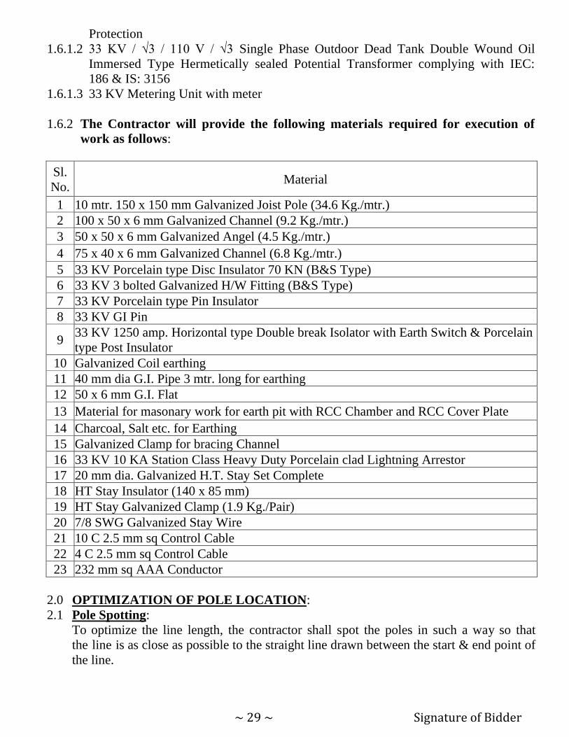
1.6.1.2 33 KV / √3 / 110 V / √3 Single Phase Outdoor Dead Tank Double Wound Oil
Immersed Type Hermetically sealed Potential Transformer complying with IEC:
186 & IS: 3156
1.6.1.3 33 KV Metering Unit with meter
1.6.2 The Contractor will provide the following materials required for execution of
work as follows:
Sl.
No. Material
1 10 mtr. 150 x 150 mm Galvanized Joist Pole (34.6 Kg./mtr.)
2 100 x 50 x 6 mm Galvanized Channel (9.2 Kg./mtr.)
3 50 x 50 x 6 mm Galvanized Angel (4.5 Kg./mtr.)
4 75 x 40 x 6 mm Galvanized Channel (6.8 Kg./mtr.)
5 33 KV Porcelain type Disc Insulator 70 KN (B&S Type)
6 33 KV 3 bolted Galvanized H/W Fitting (B&S Type)
7 33 KV Porcelain type Pin Insulator
8 33 KV GI Pin
9 33 KV 1250 amp. Horizontal type Double break Isolator with Earth Switch & Porcelain
type Post Insulator
10 Galvanized Coil earthing
11 40 mm dia G.I. Pipe 3 mtr. long for earthing
12 50 x 6 mm G.I. Flat
13 Material for masonary work for earth pit with RCC Chamber and RCC Cover Plate
14 Charcoal, Salt etc. for Earthing
15 Galvanized Clamp for bracing Channel
16 33 KV 10 KA Station Class Heavy Duty Porcelain clad Lightning Arrestor
17 20 mm dia. Galvanized H.T. Stay Set Complete
18 HT Stay Insulator (140 x 85 mm)
19 HT Stay Galvanized Clamp (1.9 Kg./Pair)
20 7/8 SWG Galvanized Stay Wire
21 10 C 2.5 mm sq Control Cable
22 4 C 2.5 mm sq Control Cable
23 232 mm sq AAA Conductor
2.0 OPTIMIZATION OF POLE LOCATION:
2.1 Pole Spotting:
To optimize the line length, the contractor shall spot the poles in such a way so that
the line is as close as possible to the straight line drawn between the start & end point of
the line.
~ 30 ~ Signature of Bidder
2.2 Details En-route:
After survey and finalization of route, the contractor shall submit detailed route map
for each line. This would be including following details:
2.3 Final Schedule:
The final schedule including Bill of quantity indicating location of poles specifically
marking locations of failure containment pole/structure, 3 3 KV line sectionalizes,
line tapping points, angle of deviation at various tension pole locations, all type of
crossings and other details shall be submitted for the approval of the owner. After
approval, the contractor shall submit six more sets of the approved documents along
with one set in reproducible form to purchaser for record purpose.
2.4 Danger Board:
The vendor shall provide & install danger plates on all 33 KV DP structures, 4- pole
structures and towers besides in all poles where high voltage equipments have to be
installed. The danger plates shall conform to REC specification No.: 57/1993.
2.5 Anti-climbing Devices:
The vendor shall provide and install anti-climbing device on all 33 KV DP structures,
towers and at all poles as per CEA guide line. This shall be done with G.I. Barbed wire
or modified spikes as specified. The barbed wire shall conform to IS: 278 (Grade A1).
The barbed wires shall be given chromatin dip as per procedure laid down in IS: 1340.
3.0 FITTINGS COMMON TO ALL LINE:
3.1 PIN INSULATOR BINDING:
The contractor shall use aluminium binding wire for binding shall be as per REC
Construction Standards No.: C-5 or better thereof.
3.2 MID SPAN COMPRESSION JOINT & REPAIR SLEEVES:
The contractor shall supply & install the Mid Span Compression Joint and Repair
Sleeves as per IS: 2121 (Part II).
3.3 GUY/STAY WIRE CLAMP:
The contractor shall supply & install Guy/Stay wire Clamp as per REC Construction
Standard G-1 or better here of as specified.
3.4 STAY/GUY SETS:
3.4.1 The Stay/Guys shall be used at the following pole locations:
3.4.1.1 At all the tapping points & dead end poles
3.4.1.2 At all the points where DT is to be installed
3.4.1.3 At all the points as per REC construction drawing No.: A-10 ( for the diversion
angle of 10 to 60 degree)
3.4.1.4 At every pole for 33 KV line
3.4.1.5 Both side poles at all the crossing for road, nalla & railway crossings etc.
~ 31 ~ Signature of Bidder
3.4.2 The arrangement and number of stay sets to be installed on different pole
structures shall be as per REC Construction Standards No.: A-23 to A-27, G-5 &
G-8. However, this shall be decided finally during erection as per the advice of
Engineer In-Charge.
3.4.3 The stay set to be installed complete in all respect and would broadly consist
of following items:
3.4.3.1 7/8 SWG G.I. Stay wire for 33 KV lines as per REC Specification No.: 46/1986
3.4.3.2 Stay Insulator type C for 33 KV line as per REC Specification No.: 21/1981
3.4.3.3 Turn Buckle, Anchor rod and plate (Hot Dipped galvanized)
3.4.3.4 Thimbles and Guy Grip
3.4.3.5 Complete stay set shall be as per REC Construction Standards no. G-1
3.4.3.6 The stay clamp is envisaged as GS structure along with other clamps brackets etc.
3.4.4 Erection of Stay Set:
3.4.4.1 The contractor shall install the stay set complete in all respect. This includes
excavation of pit in all kinds of soil with PCC in the ratio 1:2:4 as specified which
shall be placed in the bottom of the pit.
3.4.4.2 The rest (upper half) of the pit shall be filled with excavated soil duly compacted
layer by layer. An angle between 30 to 45 degrees shall be maintained between
stay wire and the pole. The stay wire shall be used with a stay insulator at a height
of 5 mtr. above ground level with GI turn buckle.
3.5 STRINGING AND INSTALLATION OF LINE WITH BARE CONDUCTORS:
3.5.1 General:
3.5.1.1 The scope of erection work shall include the cost of all labour, tools and plants
such as tension stringing equipment and all other incidental expenses in
connection with erection and stringing work. The Bidders shall indicate in the offer
the sets of stringing equipment he would deploy exclusively for work under this
package. The stringing equipments shall be of sufficient capacity to string
AAA conductor.
3.5.1.2 The Contractor shall be responsible for transportation to site of all the materials to
be provided by the Contractor as well as proper storage, insurance etc. at his own
cost, till such time the erected line is taken over by the owner.
3.5.1.3 Contractor shall set up required number of stores along the line and the exact
location of such stores shall be discussed and agreed upon with the owner.
3.5.2 Insulator Fixing:
3.5.2.1 Pin insulators shall be used on all poles while strain insulators shall be used on all
angle & dead end poles.
3.5.2.2 The special type Pin Insulators should be used for conductors more than 100
mm2.
3.5.2.3 Damaged insulators and fittings, if any, shall not be used.
3.5.2.4 Prior to fixing, all insulators shall be cleaned in a manner that those shall not
spoil, injure or scratch the surface of the insulator but in no case shall any oil be
~ 32 ~ Signature of Bidder
used for this purpose.
3.5.2.5 Torque wrench shall be used for fixing various line materials and components
such as suspension clamp for conductor, whenever recommended by the
manufacturer of the same.
3.5.3 Running Out of the Conductors:
3.5.3.1 The contractor shall be entirely responsible for any damage to the pole or
conductors during stringing. The conductors shall be run out of the drums from the
top in order to avoid damage to conductor.
3.5.3.2 A suitable braking device shall be provided to avoid damaging, loose running out
and kinking of the conductors. Care shall be taken to ensure that the conductor
does not touch and rub against the ground or objects, which could scratch or damage
the strands.
3.5.3.3 The sequence of running out shall be from the top to down i.e. the top conductor
shall be run out first, followed in succession by the side conductors. Unbalanced
loads on poles shall be avoided as far as possible.
3.5.3.4 Wherever applicable, inner phase off-line conductors shall be strung before the
stringing of the outer phases is taken up.
3.5.3.5 When lines being erected run parallel to existing energized power lines, the
Contractor shall take adequate safety precautions to protect personnel from the
potentially dangerous voltage build up due to electromagnetic and electrostatic
coupling in the pulling wire, conductors and earth wire during stringing operations.
3.5.3.6 The Contractor shall also take adequate safety precautions to protect personnel from
potentially dangerous voltage build up due to distant electrical storms or any other
reason.
3.5.4 Repairs to Conductors:
3.5.4.1 The conductor shall be continuously observed for loose or broken strands or any
other damage during the running out operations. Repair to conductors, if necessary,
shall be carried out with repair sleeves and not more than one repair sleeve will be
used in one span.
3.5.4.2 Repairing of the conductor surface shall be carried out free of cost only in case
of minor damage, scuff marks, etc. The final conductor surface shall be clean,
smooth and free from projections, sharp points, cuts, abrasions etc. After compression
the sharp edges must be smoothened by filing.
3.5.4.3 The Contractor shall be entirely responsible for any damage to the poles, insulators
etc during stringing.
3.5.5 Stringing of Conductor:
3.5.5.1 The stringing of the conductor shall be done by the standard stringing method.
3.5.5.2 The Bidder shall submit complete details of the stringing method for owner‟s
approval. Conductors shall not be allowed to hang in the stringing blocks for more
than 96 hours before being pulled to the specified sag.
3.5.5.3 Derricks/ scaffoldings or other equivalent methods shall be used to ensure that
normal services are not interrupted and any property is not damaged during
stringing operations for roads, telecommunication lines, power lines and railway
~ 33 ~ Signature of Bidder
lines. However, shut-down shall be obtained when working at crossings of overhead
power lines. The contractor shall make specific request for the same to the owner.
3.5.6 Jointing:
3.5.6.1 When approaching the end of a drum length, at least three coils shall be left in place
when the stringing operations are stopped. These coils are to be removed carefully,
and if another length is required to be run out, a joint shall be made as per the
recommendations of the accessories manufacturer.
3.5.6.2 Conductor splices shall not crack or otherwise be susceptible to damage during
stringing operation. The Contractor shall use only such equipment/methods during
conductor stringing which ensures complete compliance in this regard.
3.5.6.3 All the joints on the conductor shall be of compression type in accordance with the
recommendations of the manufacturer for which all necessary tools and equipment
like compressors, dies etc. shall be arranged by the contractor.
3.5.6.4 Each part of the joint shall be cleaned by wire brush till it is free of rust or dirt etc.
This shall be properly greased with anticorrosive compound if recommended by the
manufacturer before the final compression is carried out with the compressors.
3.5.6.5 All the joints or splices shall be made at least 30 meters away from the pole. No
joints or splices shall be made in spans crossing over main roads, railway line and
Small River spans. Not more than one joint per conductor per span shall be allowed.
3.5.6.6 The compression type fittings shall be of the self-centering type or care shall be taken
to mark the conductors to indicate when the fitting is centered properly.
3.5.6.7 During compression or splicing operation, the conductor shall be handled in such a
manner as to prevent lateral or vertical bearing against the dies. After compressing
the joint, the aluminium sleeve shall have all corners rounded, burrs and sharp edges
removed and smoothened.
3.5.6.8 To avoid any damage to the joint, the contractor shall use a suitable protector for
mid span compression joints in case they are to be passed over pulley blocks/aerial
rollers. The pulley groove size shall be such that the joint along with protection can
be passed over it smoothly.
3.5.6.9 In case AAAC is used, each press should overlap 25% of the previous press.
3.5.7 Tensioning and Sagging Operations:
3.5.7.1 The tensioning and sagging shall be done in accordance with the approved
stringing charts or sag tables.
3.5.7.2 The sag shall be checked in the first and the last section span for sections up to eight
spans and in one additional intermediate span for sections with more than eight
spans Tensioning and sagging operations shall be carried out in calm weather when
rapid changes in temperature are not likely to occur.
3.5.8 Clipping In:
3.5.8.1 Clipping of the conductors into position shall be done in accordance with the
manufacturer‟s recommendations.
3.5.8.2 Jumpers at section and angle towers shall be formed to parabolic shape to ensure
maximum clearance requirements. Pilot pin insulator shall be used, if found
~ 34 ~ Signature of Bidder
necessary, to restrict jumper swing & to ensure proper clearance to design values.
3.5.8.3 Fasteners in all fittings and accessories shall be secured in position. The security clip
shall be properly opened and sprung into position.
3.5.9 Fixing of Conductors and Earth wire Accessories:
Conductor and earth wire accessories supplied by the Contractor shall be installed
by the Contractor as per the design requirements and owner‟s instructions. While
installing the conductor and earth wire accessories, proper care shall be taken to
ensure that the surfaces are clean and smooth and that no damage occurs to any part of
the accessories or of the conductors.
4.0 REFERENCE STANDARDS:
The codes and/or standards referred to in the specifications shall govern in all cases
wherever such references are made. In case of a conflict between such codes and/or
standards and the specifications, latter shall govern. Such codes and/or standards,
referred to shall mean the latest revisions, amendments / changes adopted and published
by the relevant agencies unless otherwise indicated. Other internationally accepted
standards which ensure equal or better performance than those specified shall also be
accepted, subject to prior approval by the owner. In case no reference is given for any
item in these specifications, latest REC specification & Construction Standards shall be
referred to.
5.0 CONDUCTOR:
AAA conductors of 232 sq mm will be used in 33 KV BUS.
6.0 ERECTION WORK:
When the survey is approved, the contractor shall submit to the employer a complete
detail schedule of all materials to be used in the line. Size and length of conductor etc.
are also to be given in the list. This schedule is very essential for finalizing the
quantities of all line materials. The contractor shall furnish the same.
7.0 SCHEDULE OF ERECTION PROGRAMME:
After due approval of the detailed and check survey, the contractor shall submit to the
employer a complete detailed schedule of erection programme with a Bar-Chart for
construction of the lines indicating there in the target date of completion.
8.0 CONSTRUCTION OF FOUNDATION FOR TOWER, R. S. JOIST POLES &
PSC POLES:
8.1 ERECTION OF POLE, CONCRETING OF POLES AND COMPACTION OF
SOIL:
8.1.1 Drawing for the excavation of pits, Foundation of both wet and Black cotton soil is
enclosed which are to be adopted. If better design with less volume approved or
tested by any other distribution agencies will also be acceptable.
8.1.2 Following arrangement shall be adopted for proper erection of poles wherever
necessary and properly compacting of the soil around the base / foot of the poles under
~ 35 ~ Signature of Bidder
this package.
8.1.2.1 Excavation has to be done as per the drawing to the required depth and size. After
final excavation the pit should be dressed properly so that uneven portion and
loose soil should be removed before PCC (M-7.5) of thickness 75 mm is laid. The
base footing of the pole concreting RCC (M-15) has to be done by proper
alignment and verticality.
8.1.2.2 The verticality and leveling of pole/structure should be done by the help of
plumbob or with theodolite and leveling instrument.
8.1.2.3 In case of Joist pole Base clits and in case of PSC pole GI base plate (450 x 450 x
10) mm or RCC Pre–cast slab of size (500 x 500 x 100) mm has to be
provided over the Lean concrete.
8.2 CEMENT CONCRETE (PLAIN OR REINFORCED), STUB SETTING
GROUNDING & BACK FILLING:
8.2.1 Materials:
All materials whether to be consumed in the work or used temporarily shall conform to
relevant IS specification, unless stated otherwise, and shall be of the best approved
quality.
8.2.2 Cement:
8.2.2.1 Cement to be used in the work under the contract shall generally conform to IS:
269/455-1989. Cement bags shall be stored by the contractor in a water tight well
ventilated store sheds on raised wooden platform (raised at least 150 mm above
ground level) in such a manner as to prevent deterioration due to moisture or
intrusion of foreign matter.
8.2.2.2 Cements to be used within three months from the date of manufacture. Sub-
standard or partly set cement shall not be used and shall be removed from the site
by the contractor at his cost.
8.2.2.3 Coarse Aggregates, i.e., stone chips or stone ballast. For M15 concrete (mix 1:2:4)
the aggregate will be in the ranges from 12 mm to 20 mm size and for M 7.5
concrete (mix 1:4:8) these will be from 25 mm to 40 mm size.
8.2.3 Pole Erection:
8.2.3.1 After proper alignment, checking of verticality and leveling, the pole or structure
should be properly tied before placing of base concrete of required height. Again
the verticality and leveling should be checked.
8.2.3.2 The RCC pedestal concrete (M-15) is to be done by providing good quality of
shutters, so that there will no leakage of cement slurry during concreting. The
cooping height should be 450 mm / 750 mm above the existing ground level in
urban area and in cultivated lands respectively. The top portion of the cooping
should be made tapered.
8.2.3.3 All the bolted joints should be tightened properly by providing suitable size GI
bolt, nuts and spring washers. After completion of erection works all the bolts
should be spot welded in order to avoid theft of members.
~ 36 ~ Signature of Bidder
8.2.3.4 The back filling of locations should be done by using the excavated soil only in
layers (each layer should not be more than 500 mm) by putting water and
ramming by using wooden rammers. In no case stone of size more than 75mm
used for back filling. Back-filling has to be done 75mm above ground level or as
specified.
8.2.3.5 Curing of concrete should be done for 28 day continuously. Curing should not be
done within 24 Hours of concreting.
8.2.3.6 All the excess excavated materials and other unused materials from the concreting
site should be disposed of to a suitable site by the contractor.
a) Mixer (Running time-2 min.)
b) In case of hand mixing, 10% extra cement has to be provided. Hand mixing
should be done on GI sheet platform o n l y .
c) Poking rod may be used for compacting in locations at PSC poles only
d) Use of vibrator for compacting is mandatory.
e) Clean water (free from saline and alkaline) should be used for concreting.
f) Aggregates (both coarse and fine) used should be free from foreign materials.
g) Shutters used should not be removed before 24 hrs. of casting.
h) In case of black cotton soil borrowed earth (morum soil mixed with sand is
preferable) may be used for back filling.
i) Sufficient qty. of water should be sprinkled over backfilled earth and
chimney kept wet by using wet gunny bags.
8.2.3.7 All the persons working on tower shall wear safety helmet, safety belt and
safety shoes. Similarly all the persons working on ground shall wear safety helmet
and safety shoes.
8.2.3.8 If there is any LT/HT power line near the vicinity of tower erection, necessary
shutdown of the power line shall be obtained in writing from the concerned
Agency in order to avoid electrical hazards caused by accidental touching of
stay/Guy ropes with power line.
8.2.3.9 Safety precaution Safety shall be given utmost importance during stringing. The
following need to be ensured.
8.2.3.10 Safe working conditions shall be provided at the stringing site.
8.2.3.11 Full proof communication through walky-talkie / mobile phones shall be used in
order to avoid any damage to workmen or public on ground.
9.0 TECHNICAL SPECIFICATION OF MATERIALS / EQUIPMENTS TO BE
SUPPLIED BY BIDDER / CONTRACTOR FOR EXECUTION OF PROJECT:
The Contractor will provide the following materials required for execution of work as
follows:
Sl.
No. Material
1 10 mtr. 150 x 150 mm Galvanized Joist Pole (34.6 Kg./mtr.)
2 100 x 50 x 6 mm Galvanized Channel (9.2 Kg./mtr.)
~ 37 ~ Signature of Bidder
3 50 x 50 x 6 mm Galvanized Angel (4.5 Kg./mtr.)
4 75 x 40 x 6 mm Galvanized Channel (6.8 Kg./mtr.)
5 33 KV Porcelain type Disc Insulator 70 KN (B&S Type)
6 33 KV 3 bolted Galvanized H/W Fitting (B&S Type)
7 33 KV Porcelain type Pin Insulator
8 33 KV GI Pin
9 33 KV 1250 amp. Horizontal type Double break Isolator with Earth Switch & Porcelain
type Post Insulator
10 Galvanized Coil earthing
11 40 mm dia G.I. Pipe 3 mtr. long for earthing
12 50 x 6 mm G.I. Flat
13 Material for masonary work for earth pit with RCC Chamber and RCC Cover Plate
14 Charcoal, Salt etc. for Earthing
15 Galvanized Clamp for bracing Channel
16 33 KV 10 KA Station Class Heavy Duty Porcelain clad Lightning Arrestor
17 20 mm dia. Galvanized H.T. Stay Set Complete
18 HT Stay Insulator (140 x 85 mm)
19 HT Stay Galvanized Clamp (1.9 Kg./Pair)
20 7/8 SWG Galvanized Stay Wire
21 10 C 2.5 mm sq Control Cable
22 4 C 2.5 mm sq Control Cable
23 232 mm sq AAA Conductor
10.0 LAYING OF CABLES:
10.1 CABLE TERMINATIONS:
10.1.1 Cable terminations required are both indoor and outdoor type and invariably be of
heat shrinkable types conforming to the specifications vide Sec-iv. Alternatively
push-on or Tapex or cold shrinkable type can be used with the approval of WESCO
with appropriate sheds for rainwater in case of outdoor terminations. All the
technical particulars to establish the superiority in the performance of these joints
shall be furnished while seeking approval. The terminations shall conform to
specifications as per IS: 13573 – 1992. The instructions furnished by the
manufacturer of termination boxes/kits should strictly be followed.
10.1.2 Whenever a cable raised from the trench to end in termination, to be finally
connected to an overhead line or transformer, the following instructions should be
complied with:
10.1.2.1 One coil to made and left in the ground for future needs.
10.1.2.2 The rise of cable, immediately from the ground level should be enclosed in
suitable diameter GI pipe to height of 2 mtr.
10.1.2.3 The balance portion of the cable should be neatly curved, in „S‟ shape.
10.1.2.4 The cable and pipe should be properly fastened by using appropriate clamps
/support. The hardware of clamps shall be painted with red oxide and enamel paint
~ 38 ~ Signature of Bidder
or galvanized.
10.1.2.5 The lugs on the termination shall be compressed with a suitable compression
tool.
10.2 EARTHING AND BONDING:
The metal sheath and Armour should be efficiently bonded and earthed at all
terminals to earth electrodes provided. The cross sectional area of the bond shall be
such that the resistance of each bond connection shall not exceed the combined
resistance of an equal length of the metal sheath and Armour of the cable.
10.3 TESTING AFTER LAYING AND JOINTING:
10.3.1 All cables after laying and jointing works are completed should be tested
systematically and insulation and pressure tests should be made on all underground
cables.
10.3.2 All test results should be recorded in tabular form in logbooks kept for the purpose.
10.3.3 The cable cores should be tested for:
a) Continuity
b) Absence of cross phasing
c) Insulation resistance to earth; insulation resistance between conductors.
10.4 TESTING AND RECORD OF CABLE CONSTANTS:
When the cable is ready, just before commissioning, the cable constants viz,
the resistance, capacitance and inductance of each conductor should be determined
and recorded, along with frequency at which the values of capacitance and
inductance are determined.
10.5 GUARANTEE:
All the cable joints / termination done by the contractor shall be guaranteed
for 24 months from the date of energisation of the complete cable. In the event of
failure during the guarantee period, the restoration work shall be done free of cost
by the contractor within 24 hours of giving notice or else the expenditure incurred
by WESCO to re-do the joint / termination will be recovered from the performance
guarantee amount held with the WESCO.
10.6 CABLE RECORDS:
10.6.1 Accurate neat plans / sketches, drawn to suitable scale (1 cm = 10 M) should be
prepared and furnished by the contractor after the completion of each work.
10.6.2 All relevant information should be collected at site, during the progress of work and
preserved for preparation of drawings.
10.6.3 The following essential data should be incorporated on all drawings:
a) Size, type of cable or cables
b) Location of the cable in relation to prominent land mark property, Kerb-line
etc., with depths.

~ 39 ~ Signature of Bidder
c) The cross section showing where cables are laid in piper or ducts, giving their
sizes, type and depths.
d) Position and type of all joints
e) Location of other cables which run alongside or across the cable route.
f) Position and depths of all pipers, ducts, etc., which are met as obstruction to
the cable route.
g) Accurate lengths from joint to joint
h) Manufacturers name and drum number of the cable, between sections / joint to
joint.
11.0 NUMBER PLATE (SUPPORT): 11.1 SCOPE:
Weather proof number plate shall have unique name are to be installed on the pole
support. The plate shall be made from mild steel sheet of at least 1.6mm thick and
vitreous enameled white, with letters in signal red color (refer IS: 5-1978) on the front
side. The rear side of the plate shall also be enameled. The digits shall be as under:
110121
000001
226
Digits shall be displayed as detailed above having at-least 25mm height. The overall size
of the plate shall be 200 x 250 mm x 1.6 mm. The corners of the plate shall be rounded
off. All lettering shall be centrally spaced. The dimensions of the letters, figures and
their respective position shall be as shown above.
The size of digits and spacing between them shall be so chosen that these are uniformly
written in the space earmarked for them. The type and size of digits to be written in
English as indicated above. The plate should be provided with 6mm dia holes in
horizontal alignment for fixing to the pole by means of Galvanized MS flat clamp of 25
x 3 mm size. The nut & bolts used for fixing of plate should be of galvanized and
washers of electro-plated. The bolt should be used of at-least 6mm diameter.
11.2 TEST:
The following tests shall be carried out:
i) Visual examination as per IS: 2551-1982
ii) Dimensional check as per IS: 2551-1982
iii) Test for weather proofness as per IS: 8709-1977 (or its latest version)
11.3 NUMBERING OF TRANSFORMER/ FEEDERS/ EQUIPMENTS (IN SUB-
STATION):
All augmented/ new power transformer, Breakers, Outgoing feeders, respective control
panels, Kiosks are to be named. Base should be painted with yellow paint and black
digits should be displayed of at least 25 mm height. Experienced painter should be used
~ 40 ~ Signature of Bidder
to provide this work. LT and HT bushing should be colour coded, CT and PT panels are
to be named. The Yellow base plate should be encircled by a black strip. Naming shall
be in the local as well as English language.
11.4 NUMBERING OF CONTROL PANEL:
Name of Feeder should be displayed on front end and at rear end along with serial
number of the panel. Yellow base paint and 25 mm high black digits are to be used for
this purpose. The base paint should be encircled by a black strip. Naming shall be in the
local as well as English language.
12.0 DANGER NOTICE PLATES: 12.1 SCOPE:
This Specification covers Danger Notice Plates to be displayed in accordance with rule
No.: 35 of Indian Electricity Rules, 2003.
12.2 APPLICABLE STANDARD:
Unless otherwise modified in this specification, the Danger Notice Plates shall comply
with IS: 2551- 1982 or the latest version thereof.
12.3 DIMENSION:
12.3.1 Two sizes of Danger Notice Plates as follows are recommended:
a) For display at 415 V installations : 200 x 150 mm
b) For display at 11 KV or higher voltage installations : 250 x 200 mm
12.3.2 The corners of the plate shall be rounded off.
12.3.3 The location of fixing holes can be modified to suit the requirements of the purchaser.
12.4 LETTERING:
All letterings shall be centrally spaced. The dimensions of the letters, figures and their
respective position shall be submitted with bid. The size of letters in the words in each
language and spacing between them shall be so chosen that these are uniformly written
in the space earmarked for them.
12.5 LANGUAGE:
12.5.1 Under Rule No.: 35 of Indian Electricity Rules, 2003, the owner of every medium,
high and extra high voltage installation is required to affix permanently in a
conspicuous position. A danger notice in Hindi or English and in addition to this, in
the local language with the sign of skull and bones.
12.5.2 The type and size of lettering to be done in ENGLISH, HINDI & ODIA to be indicated
in the specimen danger notice plates and must be in line with latest Indian standards.
12.5.3 Adequate space has been provided in the specimen danger notice plates for having the
letterings in local language for the equivalent of' Danger', „415‟, „11000‟ & „Volts‟.
~ 41 ~ Signature of Bidder
12.6 MATERIAL AND FINISH:
The plate shall be made from mild steel sheet of at least 1.6mm thick and vitreous
enameled white, with letters, figures and the conventional skull and cross-bones in
signal red colour (refer IS: 5-1978) on the front side. The rear side of the plate shall
also be enameled in black colour.
12.7 TEST:
The following tests shall be carried out:
i) Visual examination as per IS: 2551-1982
ii) Dimensional check as per IS: 2551-1982
iii) Test for weather proofness as per IS: 8709-1977 (or its latest version)
12.8 MARKING:
Maker's name and trade mark and the purchaser‟s name shall be marked in such a
manner and position on the plates that it does not interfere with the other information.
12.9 PACKING:
The plates shall be packed in wooden crates suitable for rough handling and acceptable
for rail/road transport.
13.0 GALVANIZED JOIST, CHANNEL & ANGLE: 13.1 APPLICABLE STANDARDS:
The mild steel shall conform to IS: 2062 grade „A‟ modified up to date or equivalent
international standard for steel materials, documents for which shall be made available
at the time of inspection to the owner‟s representative.
13.2 GENERAL REQUIREMENTS:
Material shall be supplied as per the following sizes:
a) 10 mtr. 150 x 150 mm Galvanized Joist Pole (34.6 Kg./mtr.)
b) 100 x 50 x 6 ISMC Galvanized channel conforming to IS: 2062 grade „A‟ modified up
to date or its equivalent International Standard having length ranging from 5.5 to 13.5
meters & weight of 9.2 Kg/mtr.
c) 75 x 40 x 6 ISMC Galvanized channel conforming to IS: 2062 grade „A‟ modified up
to date or its equivalent International Standard having length ranging from 5.5 to 13.5
meters & weight of 6.8 Kg/mtr.
d) 50 x 50 x 6 mm ISA Galvanized angles conforming to IS: 2062 grade „A‟ modified up
to date or its equivalent international standard having length ranging from 5.5 to 13.5
meters & weight of 4.5 Kg/mtr.
13.3 GALVANISATION:
All above steel members shall be fabricated as per approved drawing having smooth
edge, drilled circular / elliptical holes of suitable measurements. All structural steel
members and bolts shall be galvanized as per IS: 4759 and zinc coating shall not be less

~ 42 ~ Signature of Bidder
than 610 gm/sq. meter for all structural steel members. All welds shall be 6mm filled
weld unless specified otherwise. All nuts and bolt shall be of property class 5.6 of IS:
1367. Plain washers shall be as per IS: 2016 and spring washers shall be IS: 3063
13.4 INSPECTION:
All inspection/test will be carried out by representative of owner. All tests and
inspection shall be made at the place of manufacturer unless otherwise specially agreed
upon by the manufacturer and the owner. The manufacturer shall provide all reasonable
facilities without charge to satisfy him that the material is being supplied in accordance
with the specification.
14.0 G.I. NUTS, BOLTS & WASHER (ASSORTED SIZE): 14.1 GENERAL:
14.1.1 The bolts & Nuts shall be ISI Marked Mild Steel of Black Grade “B” and shall be
round with hexagonal head.
14.1.2 The Bolts and Nuts shall be manufactured by Hot/Cold forging process neatly and
cleanly finished and shall have metric threads as per IS: 4218/1967 with its latest
amendments.
14.1.3 The dimensions of the bolts & nuts and tolerances should conform to IS: 1363 with
their latest amendments in all respect.
14.1.4 The eccentricity and angular errors of various elements shall be within specified limits
as per IS: 1367/1967 with its latest amendments the bolts & nuts shall be free from
forging and threading defects such as cuts, spats, burns, bulging taper eccentricity &
loose fill etc. which may affect their serviceability.
14.1.5 The colt heads and nuts shall be chamfered on one face only and other face shall be
machined made.
14.1.6 Mechanical property requirement of tester shall conform to IS: 1367 (Part-III): 1979
property class: 4.6 for bolts & property class: 5 for nuts as per IS: 1367 (Part VI):
1980.
14.1.7 The bolts, nuts & washer are to be galvanized with hot dip as per IS: 2633/1989 with
latest amendment.
14.1.8 The assorted size of bolts & nuts shall be supplied in well-cleaned conditions and
suitably protected against corrosion in bags of 50 Kgs.
14.2 ACCEPTANCE TEST:
The bidder should furnish test certificate from recognized Govt. Laboratory (NABL
accredited) giving the results of tests as per IS: 1367 (Part-Ill)-1979 & IS: 1367 (Part-
VI) 1980. The test certificate shall be in respect of the following for all sizes of both
bolts & nuts as applicable given below:
14.2.1 Dimensional particulars (Sampling accordance with IS: 2614 for both bolts & nuts
(tolerance as per drawing).
14.2.2 Tensile strength test on full size (for bolts minimum 400 NI sq. mm and for Nuts Proof
Stress test Mm 610 N/sq. mm).
14.2.3 Power load test on full size bolts and M-12-51400 N for 15 sec.
~ 43 ~ Signature of Bidder
14.2.4 Head soundness tests for bolts (no fracture).
14.2.5 Brinnel hardness tests or Rockwell Hardness or Vickers‟s Hardness tests for bolts min-
114 & max. 209 or min. 67 & max. 95 or min. 120 & max. 220 respectively.
14.2.6 For nuts Vickers‟s Hardness min. 130 & max. 302.
14.3 MARKING:
On the bolt head, there shall be identification marking of the manufacturer as well as
property class „4.6”. If possible property class “5” shall be marked on Nuts also. Further
„ISI‟ mark shall be marked on Gunny Bags for proper identification.
15.0 MATERIAL FOR MASONARY WORK FOR EARTH PIT: Good quality of materials to be used for masonry work for construction of earth pit and
the work to be executed as per REC guideline. The design & drawing to be approved by
WESCO Utility prior to execution of work.
16.0 CHARCOAL & SALT ETC. FOR EARTHING: Good quality of Charcoal & Salt to be used for achieving proper earthing for safety of
equipment & line and the work to be executed as per REC guideline. The design &
drawing to be approved by WESCO Utility prior to execution of work.
17.0 MATERIALS & GRADE OF CONCRETE:
17.1 Concrete:
17.1.1 Minimum grade of structural concrete shall be M-25 conforming to IS: 456.
17.1.2 Blinding concrete below foundations, cable trenches, shall be PCC of minimum grade
M- 7.5.
17.1.3 Blinding concrete under brick foundations shall be minimum 150 mm thick in PCC of
minimum grade M-10.
17.2 Cement:
17.2.1 Cement shall be ordinary Portland cement conforming to IS: 269, Portland slag cement
conforming to IS: 455, Fly ash based pozzolona cement conforming to IS: 1489 (Part–
I) or Portland pozzolona cement conforming to IS: 1489 (Part–II).
17.2.2 For miscellaneous concrete works, Fly ash based Portland pozzolona cement or Blast
slag cement may be used as per the specifications if directed by the Project Manager.
17.2.3 Ordinary Portland cement conforming to IS: 269 shall be used for all structures
requiring grade of concrete M – 25 or above. Supply of all types of cement shall be in
Bidder‟s scope.
17.3 Reinforcement Steel:
HYSD bars (Fe: 415) conforming to IS: 1786 shall be used for all structures. Supply of
reinforcement steel shall be in bidder‟s scope.
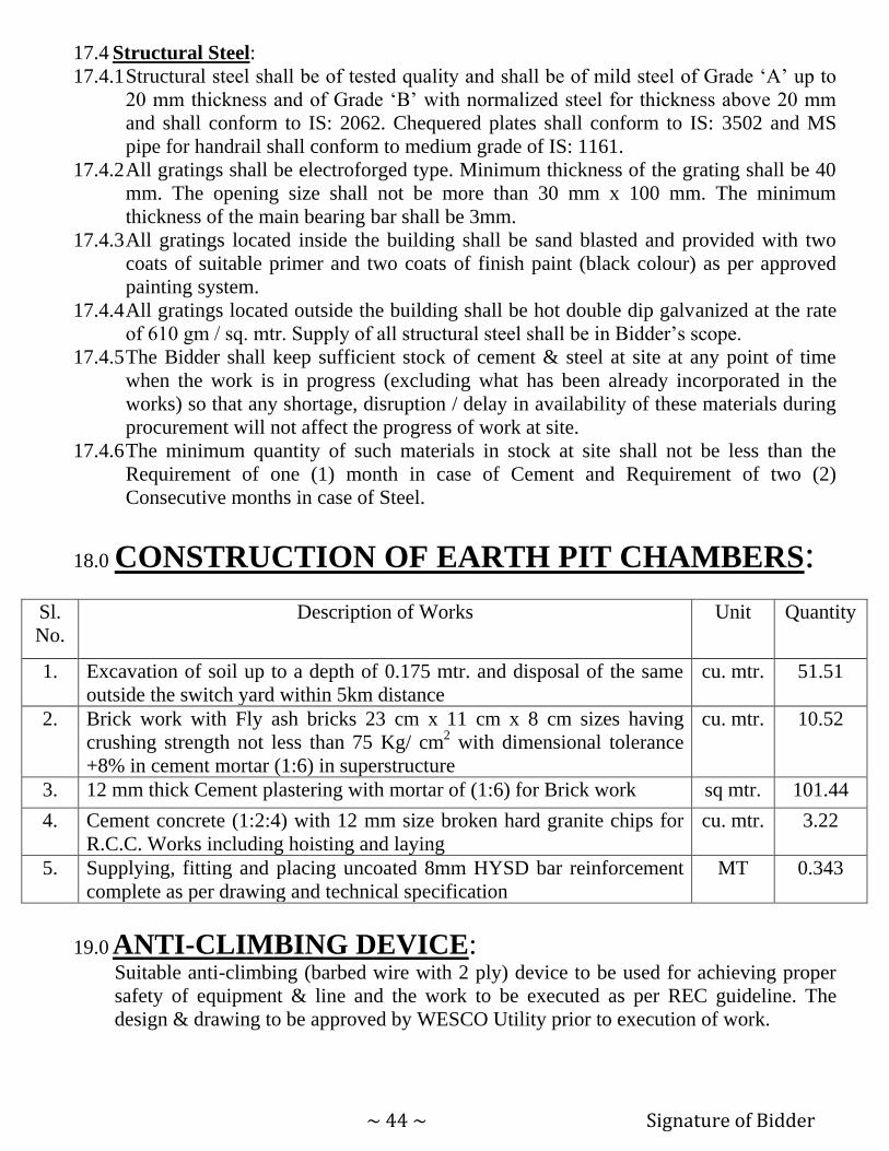
~ 44 ~ Signature of Bidder
17.4 Structural Steel:
17.4.1 Structural steel shall be of tested quality and shall be of mild steel of Grade „A‟ up to
20 mm thickness and of Grade „B‟ with normalized steel for thickness above 20 mm
and shall conform to IS: 2062. Chequered plates shall conform to IS: 3502 and MS
pipe for handrail shall conform to medium grade of IS: 1161.
17.4.2 All gratings shall be electroforged type. Minimum thickness of the grating shall be 40
mm. The opening size shall not be more than 30 mm x 100 mm. The minimum
thickness of the main bearing bar shall be 3mm.
17.4.3 All gratings located inside the building shall be sand blasted and provided with two
coats of suitable primer and two coats of finish paint (black colour) as per approved
painting system.
17.4.4 All gratings located outside the building shall be hot double dip galvanized at the rate
of 610 gm / sq. mtr. Supply of all structural steel shall be in Bidder‟s scope.
17.4.5 The Bidder shall keep sufficient stock of cement & steel at site at any point of time
when the work is in progress (excluding what has been already incorporated in the
works) so that any shortage, disruption / delay in availability of these materials during
procurement will not affect the progress of work at site.
17.4.6 The minimum quantity of such materials in stock at site shall not be less than the
Requirement of one (1) month in case of Cement and Requirement of two (2)
Consecutive months in case of Steel.
18.0 CONSTRUCTION OF EARTH PIT CHAMBERS:
Sl.
No.
Description of Works Unit Quantity
1. Excavation of soil up to a depth of 0.175 mtr. and disposal of the same
outside the switch yard within 5km distance
cu. mtr. 51.51
2. Brick work with Fly ash bricks 23 cm x 11 cm x 8 cm sizes having
crushing strength not less than 75 Kg/ cm2 with dimensional tolerance
+8% in cement mortar (1:6) in superstructure
cu. mtr. 10.52
3. 12 mm thick Cement plastering with mortar of (1:6) for Brick work sq mtr. 101.44
4. Cement concrete (1:2:4) with 12 mm size broken hard granite chips for
R.C.C. Works including hoisting and laying
cu. mtr. 3.22
5. Supplying, fitting and placing uncoated 8mm HYSD bar reinforcement
complete as per drawing and technical specification
MT 0.343
19.0 ANTI-CLIMBING DEVICE: Suitable anti-climbing (barbed wire with 2 ply) device to be used for achieving proper
safety of equipment & line and the work to be executed as per REC guideline. The
design & drawing to be approved by WESCO Utility prior to execution of work.

~ 45 ~ Signature of Bidder
20.0 33 KV 3 POLE 1250 AMPERE HORIZONTAL TYPE
DOUBLE BREAK ISOLATOR WITH EARTH SWITCH
(WITHOUT MOTOR) WITH PORCELAIN POST
INSULATOR:
20.1 SCOPE:
This specification provides for design, manufacture, testing at manufactures works,
delivery of outdoor station type 33 KV (Local) manual operating mechanism 3-Pole
isolating with earthing blades and complete in all respect with bi-metallic connectors.
Operating mechanism, fixing details etc. shall be as described herein.
20.2 PARTICULARS OF THE SYSTEM:
The isolators to be provided under this specification are intended to be used on 3 phase
A.C. 50 cycles, effectively grounded system. The nominal system voltage is 33 KV.
20.3 STANDARD:
The Isolator shall comply in all respects with IS: 9921 (Part-1)/1981 (reaffirmed in
1992), IS: 9921 (Part- 2 & 3)/1982 (reaffirmed in 1992), IS: 9921 (Part- 4)/1985
(reaffirmed in 1992), IS: 2544/1973 (1st revision, Amendment-4, reaffirmed in 1991) or
IEC Publication No.: 129. Equipment meeting any other authoritative standard which
ensures an equal or better quality than the standard mentioned above will also be
accepted.
20.4 TYPE & RATING:
20.4.1 Isolators shall have three posts per phase, triple pole single throw, gang operated out-
door type silver plated contacts with horizontal operating blade and isolators posts
arranged vertically.
20.4.2 The isolators will be double break type. Rotating blade feature with pressure relieving
contacts is necessary, i.e., the isolator shall be described in detail along-with the offer.
20.4.3 However, the design of turn & twist arrangement shall be subject to owner‟s approval
(Banging type feature is not acceptable). All isolators shall operate through 90 degree
from their fully closed position to fully open position, so that the break is distinct and
clearly visible from the ground level.
20.4.4 The equipment offered by the tenderer shall be designed for a normal current rating of
1250 A for 33 KV suitable for continuous service at the system voltage specified
herein.
20.4.5 The isolators are not required to operate under load but they must be called upon to
handle magnetization currents of the power transformers and capacitive currents of
bushings, bus-bars connections, very short lengths of cables and current of voltage
transformers.
20.4.6 The rated insulation strength of the equipment shall not be lower than the levels
specified in IS: 9921 or IEC publication No.: 129, which are reproduced below:
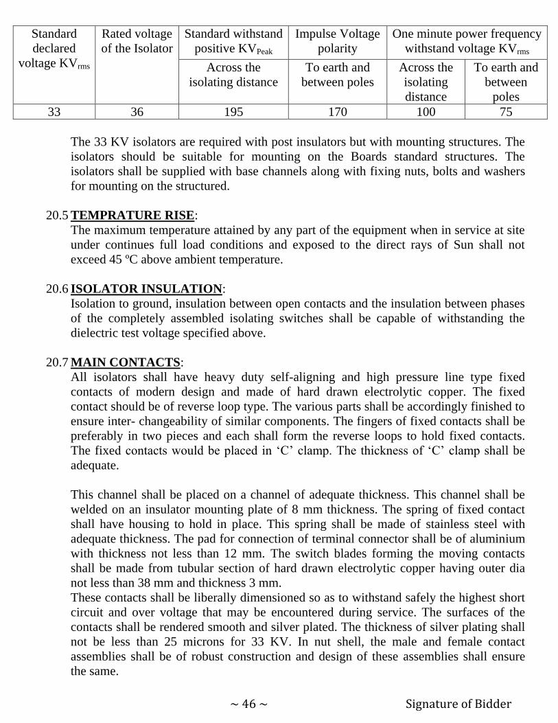
~ 46 ~ Signature of Bidder
Standard
declared
voltage KVrms
Rated voltage
of the Isolator
Standard withstand
positive KVPeak
Impulse Voltage
polarity
One minute power frequency
withstand voltage KVrms
Across the
isolating distance
To earth and
between poles
Across the
isolating
distance
To earth and
between
poles
33 36 195 170 100 75
The 33 KV isolators are required with post insulators but with mounting structures. The
isolators should be suitable for mounting on the Boards standard structures. The
isolators shall be supplied with base channels along with fixing nuts, bolts and washers
for mounting on the structured.
20.5 TEMPRATURE RISE:
The maximum temperature attained by any part of the equipment when in service at site
under continues full load conditions and exposed to the direct rays of Sun shall not
exceed 45 ºC above ambient temperature.
20.6 ISOLATOR INSULATION:
Isolation to ground, insulation between open contacts and the insulation between phases
of the completely assembled isolating switches shall be capable of withstanding the
dielectric test voltage specified above.
20.7 MAIN CONTACTS:
All isolators shall have heavy duty self-aligning and high pressure line type fixed
contacts of modern design and made of hard drawn electrolytic copper. The fixed
contact should be of reverse loop type. The various parts shall be accordingly finished to
ensure inter- changeability of similar components. The fingers of fixed contacts shall be
preferably in two pieces and each shall form the reverse loops to hold fixed contacts.
The fixed contacts would be placed in „C‟ clamp. The thickness of „C‟ clamp shall be
adequate.
This channel shall be placed on a channel of adequate thickness. This channel shall be
welded on an insulator mounting plate of 8 mm thickness. The spring of fixed contact
shall have housing to hold in place. This spring shall be made of stainless steel with
adequate thickness. The pad for connection of terminal connector shall be of aluminium
with thickness not less than 12 mm. The switch blades forming the moving contacts
shall be made from tubular section of hard drawn electrolytic copper having outer dia
not less than 38 mm and thickness 3 mm.
These contacts shall be liberally dimensioned so as to withstand safely the highest short
circuit and over voltage that may be encountered during service. The surfaces of the
contacts shall be rendered smooth and silver plated. The thickness of silver plating shall
not be less than 25 microns for 33 KV. In nut shell, the male and female contact
assemblies shall be of robust construction and design of these assemblies shall ensure
the same.
~ 47 ~ Signature of Bidder
a) Electro-dynamic withstands ability during short circuit without any risk of repulsion of
contacts.
b) The current density in the copper parts shall not be less than 2 Amp/sq.mm and
aluminium parts shall be less than 1 Amp/sq.mm.
c) Thermal withstands ability during short circuit.
d) Constant contact pressure even when the live parts of the insulator stacks are subjected
to tensile stresses due to linear expansion of connected bus bar of flexible conductors
either because of temperature verification or strong winds.
e) Wiping action during closing and opening.
f) Self-alignment assuring closing of the switch without minute adjustment.
The earthing switch should be provided with three sets of suitable type of fixed contacts
below the fixed contacts assemblies of the main switch on the incoming supply side and
the sets of moving contacts having ganged operation. These contacts shall be fabricated
out of electrolytic copper for 33 KV isolators with earth switch and designed to
withstand current on the line.
a) Arcing contacts / Horn : Arcing contacts are not required
b) Auxiliary switches : Auxiliary switches are not required
20.8 CONNECTORS:
The connectors for 33 KV isolator shall be made of Aluminium alloy LM-9 or LM-25
and shall be suitable for Raccoon/Dog conductors for 33 KV with horizontal and
vertical takeoff arrangement. The details in regard to dimensions, the number of bolts to
be provided, material and manufacture shall be furnished by the bidder for owner‟s
approval before manufacturing. The groove provided in the connection should be able to
accommodate conductor size mentioned above smoothly. The clamps to be offered
should be manufactured by gravity die-casting method only and not by sand casting
process. It is necessary that suitable clamps are offered along with the isolator and also it
is obligatory to give complete technical particular of clamps along with the drawing, as
per details given above and also as per following detail.
a) The terminal connector shall be manufactured and tested as per IS: 5561.
b) All castings shall be free from blow holes, surface blisters, cracks and cavities.
c) All the sharp edges shall be blurred and rounded off.
d) No part of the clamp shall be less than 12 mm thick.
e) All current carrying parts shall be designed and manufactured to have minimum
contact resistance.
f) Connectors shall be designed to be corona free in accordance with the requirement
of IS: 5561.
g) All nuts and bolts shall be made of stainless steel only. Bimetallic sleeve/liner shall
be 2 mm thick.
h) Wherever necessary, bi-metallic strip of standard quality and adequate dimension
shall be used.
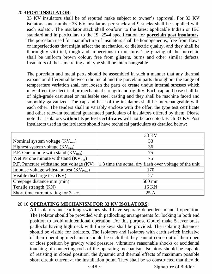
~ 48 ~ Signature of Bidder
20.9 POST INSULATOR:
33 KV insulators shall be of reputed make subject to owner‟s approval. For 33 KV
isolators, one number 33 KV insulators per stack and 9 stacks shall be supplied with
each isolator. The insulator stack shall conform to the latest applicable Indian or IEC
standard and in particulars to the IS: 2544 specification for porcelain post insulators.
The porcelain used for manufacture of insulators shall be homogeneous, free from flaws
or imperfections that might affect the mechanical or dielectric quality, and they shall be
thoroughly vitrified, tough and impervious to moisture. The glazing of the porcelain
shall be uniform brown colour, free from glisters, burns and other similar defects.
Insulators of the same rating and type shall be interchangeable.
The porcelain and metal parts should be assembled in such a manner that any thermal
expansion differential between the metal and the porcelain parts throughout the range of
temperature variation shall not loosen the parts or create undue internal stresses which
may affect the electrical or mechanical strength and rigidity. Each cap and base shall be
of high-grade cast steel or malleable steel casting and they shall be machine faced and
smoothly galvanized. The cap and base of the insulators shall be interchangeable with
each other. The tenders shall in variably enclose with the offer, the type test certificate
and other relevant technical guaranteed particulars of insulators offered by them. Please
note that isolators without type test certificates will not be accepted. Each 33 KV Post
Insulators used in the isolators should have technical particulars as detailed below:
33 KV
Nominal system voltage (KVrms) 33
Highest system voltage (KVrms) 36
P.F. One minute with stand (KVrms) 75
Wet PF one minute withstand (KVrms) 75
P.F. Puncture withstand test voltage (KV) 1.3 time the actual dry flash over voltage of the unit
Impulse voltage withstand test (KVPeak) 170
Visible discharge test (KV) 27
Creepage distance mm (min) 580 mm
Tensile strength (KN) 16 KN
Short time current rating for 3 sec. 25 A
20.10 OPERATING MECHANISM FOR 33 KV ISOLATORS:
All Isolators and earthing switches shall have separate dependent manual operation.
The Isolator should be provided with padlocking arrangements for locking in both end
position to avoid unintentional operation. For this purpose Godrej make 5 lever brass
padlocks having high neck with three keys shall be provided. The isolating distances
should be visible for isolators. The Isolators and Isolators with earth switch inclusive
of their operating mechanism should be such that they cannot come out of their open
or close position by gravity wind pressure, vibrations reasonable shocks or accidental
touching of connecting rods of the operating mechanism. Isolators should be capable
of resisting in closed position, the dynamic and thermal effects of maximum possible
short circuit current at the installation point. They shall be so constructed that they do

~ 49 ~ Signature of Bidder
not open under the influence of the short circuit current. The operating mechanism
should be of robust construction and easy to operate by a single person and
conveniently located for local operation in the switchyard. Provision for earthing of
operating handle by means of 8 SWG GS wire must be made.
20.11 PIPES:
Tandem pipes operating handle shall be class „B‟ ISI marked type having at least 24
mm internal diameter for 33 KV isolator. The operating pipe shall also be of class „B‟
ISI marked with internal diameter of at least 38 mm for 33 KV isolators. The pipe shall
be terminated in to suitable universal type joints between the insulator bottom bearing
and operating mechanism.
20.12 BASE CHANNEL:
The Isolator shall be mounted on base fabricated from steel channel section of
adequate size not less than 100 x 50 x 6 mm for 33 KV. To withstand total weight of
isolator and insulator and also all the forces that may encounter by the isolator during
services, suitable holes shall be provided on this base channel to facilitate it‟s
mounting on our standard structures. The steel channel in each phase shall be mounted
in vertical position and over it two mounting plates at least 8 mm thick with suitable
nuts and bolts shall be provided for minor adjustment at site.
20.13 CLEARANCES:
We have adopted the following minimum clearance for isolators in our system. The
bidder should therefore keep the same in view while submitting their offers:
Description Center distance between Poles (Center to
Center), i.e., Phase to Phase clearance
Distance between center lines of
outer posts on same pole
33 KV Isolator 120 cm 96 cm
21.0 30 KV 10 KA STATION CLASS HEAVY DUTY TYPE
PORCELAIN CLAD LIGHTNING ARRESTOR: 21.1 30 KV VOLTAGE CLASS SURGE ARRESTORS:
Lightning Arrestors at Grid Substation shall be of Station class only in 33 KV System.
21.2 INTRODUCTION:
The section covers the specification of 33 KV voltage level, 10 KA, Station class heavy
duty, gapless metal (zinc) oxide Surge Arrestors complete with insulating base, terminal
clamps, complete fittings & accessories for installation on outdoor type 33 KV
switchgear/transmission lines / transformers.
21.3 STANDARDS:
The design, manufacture and performance of Surge Arrestors shall comply with IS:
3070 Part-3 and other specific requirements stipulated in the specification. Unless
otherwise specified, the equipment, material and processes shall conform to the latest

~ 50 ~ Signature of Bidder
applicable Indian/International Standards as listed hereunder:
IS: 2071-1993 (Part-1) Methods of High Voltage Testing General Definitions & Test Requirements
IS: 2071-1974(Part-2) Test Procedures
IS: 2629-1985 Recommended Practice for hot dip galvanizing on Iron & Steel
IS: 2633-1986 Method for Testing uniformity of coating of zinc coated Articles
IS: 3070-1993 (Part –3) Specification for surge arrestor for alternating current systems. Metal-Oxide
lightening Arrestors without gaps
IS: 4759-1996 Specification for hot dip zinc coating on Structural Steel and Other allied
products
IS: 5621-1980 Hollow Insulators for use in Electrical Equipment
IS: 6209-1982 Methods of Partial discharge measurement
IS: 6745 Method for determination of mass of zinc coating on zinc coated iron and
steel articles
ANSI/IEEE-C:.62.11 Metal oxide, Surge Arrestor for AC Power Circuits
IEC: 60099-4 Surge Arrestors
The equipment complying with any other internationally accepted standards shall also
be considered if it ensures performance equivalent to or superior to the Indian Standards.
21.4 GENERAL REQUIREMENT:
21.4.1 The metal oxide gap less Surge Arrestor without any series or shunt gap shall be
suitable for protection of 33 KV switchgear, transformers, associated equipment and
33 KV lines from voltage surges resulting from natural disturbance like lightning as
well as system disturbances.
21.4.2 The surge arrestor shall draw negligible current at operating voltage and at the same
time offer least resistance during the flow of surge current.
21.4.3 The surge arrestor shall consist of non-linear resistor elements placed in series and
housed in electrical grade porcelain housing / silicon polymeric of specified creepage
distance.
21.4.4 The assembly shall be hermetically sealed with suitable rubber gaskets with effective
sealing system arrangement to prevent ingress of moisture.
21.4.5 The surge arrestor shall be provided with line and earth terminals of suitable size. The
ground side terminal of surge arrestor shall be connected with 25 x 6 mm galvanized
strip, one end connected to the surge arrestor and second end to a separate ground
electrode. The bidder shall also recommend the procedure which shall be followed in
providing the earthing system to the Surge Arrestor.
21.4.6 The surge arrestor shall not operate under power frequency and temporary over
voltage conditions but under surge conditions, the surge arrestor shall change over to
the conducting mode.
21.4.7 The surge arrestor shall be suitable for circuit breaker performing 0-0.3 sec.-CO-3 min
– CO - duty in the system.
21.4.8 Surge arrestors shall have a suitable pressure relief system to avoid damage to the
porcelain/silicon polymeric housing and providing path for flow of rated fault currents
in the event of arrestor failure.

~ 51 ~ Signature of Bidder
21.4.9 The reference current of the arrestor shall be high enough to eliminate the influence of
grading and stray capacitance on the measured reference voltage.
21.4.10 The arrestors for 33 KV system shall be suitable for mounting on transformers, Bus,
Line & structure as per scheme. The supplier shall furnish the drawing indicating the
dimensions, weights etc. of the surge arrestors for the design of mounting Structure.
21.4.11 The arrestor shall be capable of handling terminal energy for high surges, external
pollution and transient over voltage and have low losses at operating voltages.
21.5 ARRESTOR HOUSING:
21.5.1 The arrestor housing shall be made up of porcelain housing and shall be homogenous,
free from laminations, cavities and other flaws of imperfections that might affect the
mechanical and dielectric quality. The housing shall be of uniform brown (for
porcelain) colour, free from blisters, burrs and other similar defects. Arrestors shall be
complete with fasteners for stacking units together and terminal connectors.
21.5.2 The housing shall be so coordinated that external flashover shall not occur due to
application of any impulse or switching surge voltage up to the maximum design value
for arrestor. The arrestors shall not fail due to contamination. The 33 KV arrestors
housing shall be designed for pressure relief class as given in Technical Parameters of
the specification. Sealed housings shall exhibit no measurable leakage.
21.6 FITTINGS & ACCESSORIES:
21.6.1 The surge arrestor shall be complete with fasteners for stacking units together and
terminal connectors.
21.6.2 The terminals shall be non-magnetic, corrosion proof, robust and of adequate size and
shall be so located that incoming and outgoing connections are made with minimum
possible bends. The top metal cap and base of surge arrestor shall be galvanized. The
line terminal shall have a built in clamping device which can be adjusted for both
horizontal and vertical takeoff.
21.7 TEST:
21.7.1 TEST ON SURGE ARRESTORS:
The Surge Arrestors offered shall be type tested and shall be subjected to routine and
acceptance tests in accordance with IS: 3070 (Part-3)/IEC: 60099-4. In addition, the
suitability of the surge arresters shall also be established for the followings.
i) Acceptance Test:
a) Measurement of power frequency reference voltage of arrester units.
b) Lightning impulse residual voltage on arrester units (IEC clause 6.3.2)
c) Internal ionization or partial discharge test
ii) Special Acceptance Test:
a) Thermal stability test (IEC: 99-4 Clause: 7.2.2)
b) Watt loss test

~ 52 ~ Signature of Bidder
iii) Routine Test:
a) Measurement of reference voltage
b) Residual voltage test of arrester unit
c) Internal ionization or partial discharge test
d) Sealing test
e) Verticality check on completely assembled surge arresters as a sample test on
each lot if applicable.
iv) Type Test:
Following shall be type test as per IS: 3070 (Part 3): 1993 or its latest amendment.
1) Insulation Withstand Test:
a) Lightning Impulse
b) Power Frequency (Dry/Wet)
2) Residual Voltage Test:
a) Steep current impulse residual voltage test
b) Lightning impulse residual voltage test
c) Switching Impulse Residual voltage test
3) Long duration current impulse withstand test
4) Switching surge operating duty test
5) Power frequency voltage Vs. Time characteristics
6) Accelerated Ageing test
7) Pressure relief test:
a) High Current
b) Low Current
8) Artificial pollution test (for porcelain housing)
9) Seismic Test
10) Partial Discharge test
11) Bending test
12) Temperature cycle test (for porcelain housing)
13) Porosity test (for porcelain housing)
14) Galvanizing test on metal parts
15) Seal Leakage test (for porcelain housing)
16) Seal leak test and operation tests ( for surge monitor)
17) Weather ageing test (for polymer housing)
21.7.2 The maximum residual voltages corresponding to nominal discharge current of 10 KA
for steep current, impulse residual voltage test, lightning impulse protection level and
switching impulse level shall generally conform to Annex-K of IEC: 99-4.
21.7.3 The contractor shall furnish the copies of the type tests and the characteristics curves
between the residual voltage and nominal discharge current of the offered surge
arrestor and power frequency voltage v/s time characteristic of the surge arrestor
subsequent to impulse energy consumption as per clause No.: 6.6.7 of IS: 3070 (Part-
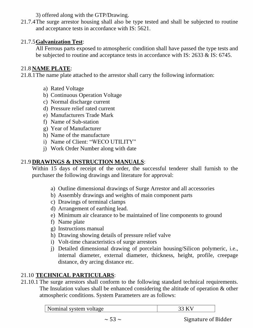
~ 53 ~ Signature of Bidder
3) offered along with the GTP/Drawing.
21.7.4 The surge arrestor housing shall also be type tested and shall be subjected to routine
and acceptance tests in accordance with IS: 5621.
21.7.5 Galvanization Test:
All Ferrous parts exposed to atmospheric condition shall have passed the type tests and
be subjected to routine and acceptance tests in accordance with IS: 2633 & IS: 6745.
21.8 NAME PLATE:
21.8.1 The name plate attached to the arrestor shall carry the following information:
a) Rated Voltage
b) Continuous Operation Voltage
c) Normal discharge current
d) Pressure relief rated current
e) Manufacturers Trade Mark
f) Name of Sub-station
g) Year of Manufacturer
h) Name of the manufacture
i) Name of Client: “WECO UTILITY”
j) Work Order Number along with date
21.9 DRAWINGS & INSTRUCTION MANUALS:
Within 15 days of receipt of the order, the successful tenderer shall furnish to the
purchaser the following drawings and literature for approval:
a) Outline dimensional drawings of Surge Arrestor and all accessories
b) Assembly drawings and weights of main component parts
c) Drawings of terminal clamps
d) Arrangement of earthing lead.
e) Minimum air clearance to be maintained of line components to ground
f) Name plate
g) Instructions manual
h) Drawing showing details of pressure relief valve
i) Volt-time characteristics of surge arrestors
j) Detailed dimensional drawing of porcelain housing/Silicon polymeric, i.e.,
internal diameter, external diameter, thickness, height, profile, creepage
distance, dry arcing distance etc.
21.10 TECHNICAL PARTICULARS:
21.10.1 The surge arrestors shall conform to the following standard technical requirements.
The Insulation values shall be enhanced considering the altitude of operation & other
atmospheric conditions. System Parameters are as follows:
Nominal system voltage 33 KV
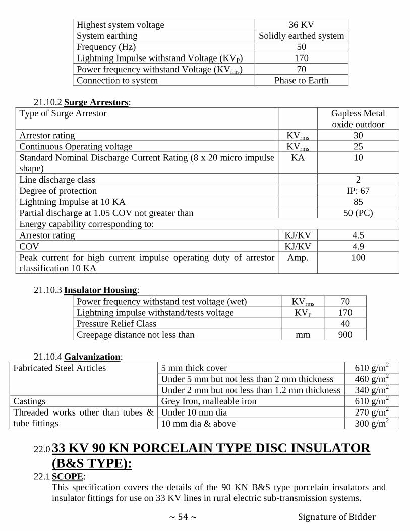
~ 54 ~ Signature of Bidder
Highest system voltage 36 KV
System earthing Solidly earthed system
Frequency (Hz) 50
Lightning Impulse withstand Voltage (KVP) 170
Power frequency withstand Voltage (KVrms) 70
Connection to system Phase to Earth
21.10.2 Surge Arrestors:
Type of Surge Arrestor Gapless Metal
oxide outdoor
Arrestor rating KVrms 30
Continuous Operating voltage KVrms 25
Standard Nominal Discharge Current Rating (8 x 20 micro impulse
shape)
KA 10
Line discharge class 2
Degree of protection IP: 67
Lightning Impulse at 10 KA 85
Partial discharge at 1.05 COV not greater than 50 (PC)
Energy capability corresponding to:
Arrestor rating KJ/KV 4.5
COV KJ/KV 4.9
Peak current for high current impulse operating duty of arrestor
classification 10 KA
Amp. 100
21.10.3 Insulator Housing:
Power frequency withstand test voltage (wet) KVrms 70
Lightning impulse withstand/tests voltage KVP 170
Pressure Relief Class 40
Creepage distance not less than mm 900
21.10.4 Galvanization:
Fabricated Steel Articles 5 mm thick cover 610 g/m2
Under 5 mm but not less than 2 mm thickness 460 g/m2
Under 2 mm but not less than 1.2 mm thickness 340 g/m2
Castings Grey Iron, malleable iron 610 g/m2
Threaded works other than tubes &
tube fittings
Under 10 mm dia 270 g/m2
10 mm dia & above 300 g/m2
22.0 33 KV 90 KN PORCELAIN TYPE DISC INSULATOR
(B&S TYPE): 22.1 SCOPE:
This specification covers the details of the 90 KN B&S type porcelain insulators and
insulator fittings for use on 33 KV lines in rural electric sub-transmission systems.
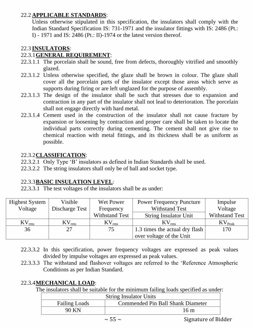
~ 55 ~ Signature of Bidder
22.2 APPLICABLE STANDARDS:
Unless otherwise stipulated in this specification, the insulators shall comply with the
Indian Standard Specification IS: 731-1971 and the insulator fittings with IS: 2486 (Pt.:
I) - 1971 and IS: 2486 (Pt.: II)-1974 or the latest version thereof.
22.3 INSULATORS:
22.3.1 GENERAL REQUIREMENT:
22.3.1.1 The porcelain shall be sound, free from defects, thoroughly vitrified and smoothly
glazed.
22.3.1.2 Unless otherwise specified, the glaze shall be brown in colour. The glaze shall
cover all the porcelain parts of the insulator except those areas which serve as
supports during firing or are left unglazed for the purpose of assembly.
22.3.1.3 The design of the insulator shall be such that stresses due to expansion and
contraction in any part of the insulator shall not lead to deterioration. The porcelain
shall not engage directly with hard metal.
22.3.1.4 Cement used in the construction of the insulator shall not cause fracture by
expansion or loosening by contraction and proper care shall be taken to locate the
individual parts correctly during cementing. The cement shall not give rise to
chemical reaction with metal fittings, and its thickness shall be as uniform as
possible.
22.3.2 CLASSIFICATION:
22.3.2.1 Only Type „B‟ insulators as defined in Indian Standards shall be used.
22.3.2.2 The string insulators shall only be of ball and socket type.
22.3.3 BASIC INSULATION LEVEL:
22.3.3.1 The test voltages of the insulators shall be as under:
Highest System
Voltage
Visible
Discharge Test
Wet Power
Frequency
Withstand Test
Power Frequency Puncture
Withstand Test
Impulse
Voltage
Withstand Test String Insulator Unit
KVrms KVrms KVrms KVrms KVPeak
36 27 75 1.3 times the actual dry flash
over voltage of the Unit
170
22.3.3.2 In this specification, power frequency voltages are expressed as peak values
divided by impulse voltages are expressed as peak values.
22.3.3.3 The withstand and flashover voltages are referred to the „Reference Atmospheric
Conditions as per Indian Standard.
22.3.4 MECHANICAL LOAD:
The insulators shall be suitable for the minimum failing loads specified as under:
String Insulator Units
Failing Loads Commended Pin Ball Shank Diameter
90 KN 16 m
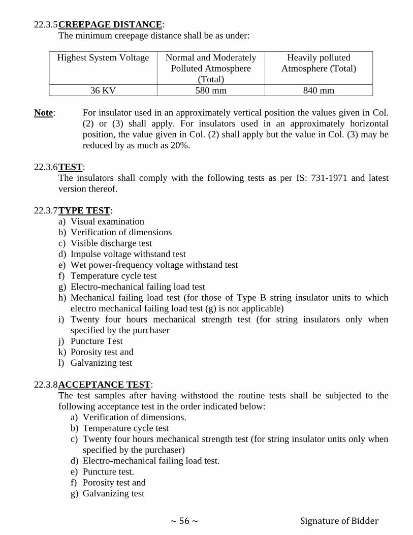
~ 56 ~ Signature of Bidder
22.3.5 CREEPAGE DISTANCE:
The minimum creepage distance shall be as under:
Highest System Voltage Normal and Moderately
Polluted Atmosphere
(Total)
Heavily polluted
Atmosphere (Total)
36 KV 580 mm 840 mm
Note: For insulator used in an approximately vertical position the values given in Col.
(2) or (3) shall apply. For insulators used in an approximately horizontal
position, the value given in Col. (2) shall apply but the value in Col. (3) may be
reduced by as much as 20%.
22.3.6 TEST:
The insulators shall comply with the following tests as per IS: 731-1971 and latest
version thereof.
22.3.7 TYPE TEST:
a) Visual examination
b) Verification of dimensions
c) Visible discharge test
d) Impulse voltage withstand test
e) Wet power-frequency voltage withstand test
f) Temperature cycle test
g) Electro-mechanical failing load test
h) Mechanical failing load test (for those of Type B string insulator units to which
electro mechanical failing load test (g) is not applicable)
i) Twenty four hours mechanical strength test (for string insulators only when
specified by the purchaser
j) Puncture Test
k) Porosity test and
l) Galvanizing test
22.3.8 ACCEPTANCE TEST:
The test samples after having withstood the routine tests shall be subjected to the
following acceptance test in the order indicated below:
a) Verification of dimensions.
b) Temperature cycle test
c) Twenty four hours mechanical strength test (for string insulator units only when
specified by the purchaser)
d) Electro-mechanical failing load test.
e) Puncture test.
f) Porosity test and
g) Galvanizing test
~ 57 ~ Signature of Bidder
22.3.9 ROUTINE TEST:
a) Visual examination
b) Mechanical routine test
c) Electrical routine test
22.3.10 MARKING:
22.3.10.1 Each insulator shall be legibly and indelibly marked to show the following:
a) Name or trade mark of the manufacturer
b) Month and year of manufacture
c) Minimum failing load in Newton
d) Country of the manufacture and
e) ISI Certification mark, if any
22.3.10.2 Marking on porcelain shall be printed and shall be applied before firing.
22.3.11 PACKING:
All insulators (without fittings) shall be packed in wooden crates suitable for easy but
rough handling and acceptable for rail transport. Where more than one insulator is
packed in a crate, wooden separators shall be fixed between the insulators to keep
individual insulators in position without movement within the crate. Disc insulators,
however, may be assembled in string and packed inside a crate to prevent movement.
23.0 33 KV 4 BOLTED HARDWARE FITTINGS (B&S
TYPE): 23.1 GENERAL REQUIREMENT:
23.1.1 All forgings and castings shall be of good finish and free of flaws and other defects.
The edges on the outside of fittings, such as at the ball socket and holes shall be
rounded.
23.1.2 All parts of different fittings which provide for interconnection shall be made such that
sufficient clearance is provided at the connection point to ensure free movement and
suspension of the insulator string assembly. All ball and socket connections shall be
free in this manner but care shall be taken that too much clearance between ball and
socket is avoided.
23.1.3 All ferrous fittings and the parts other than those of stainless steel, shall be galvanized.
Small fittings like spring washers, nuts, etc. may be electro-galvanized.
23.2 TYPE & DIMENSION:
23.2.1 Only ball and socket type insulator sets shall be used. The nominal dimensions of the
ball and sockets, ball eye and cross-arm straps.
23.2.2 Strain clamps shall be suitable for ACSR conductors 7/3.35 mm (50 mm2 Al. area),
7/4.09 mm (80 mm2 Al. area) and 6/4.72 mm + 7/1.57 mm (100 mm
2 Al. area). The
ultimate strength of clamps shall not be less than 41 KN.
~ 58 ~ Signature of Bidder
23.3 TEST:
String insulator fittings shall comply with the following tests as per IS: 2486 (Pt. I).
23.3.1 TYPE TEST:
a) Slip strength test
b) Mechanical test
c) Electrical resistance test
d) Heating cycle test
e) Verification of dimensions
f) Galvanizing/Electroplating test
g) Visual examination test
23.3.2 ACCEPTANCE TEST:
a) Verification of dimensions
b) Galvanizing/Electroplating test
c) Mechanical tests
23.3.3 ROUTINE TEST:
a) Visual examination test and
b) Routine mechanical test
23.4 MARKING:
The caps and clamps shall have marked on them the following:
a) Name or trade mark of the manufacturer and
b) Year of manufacture
23.5 PACKING:
23.5.1 For packing of GI pins, strain clamps and related hardware, double gunny bags (or
wooden cases, if deemed necessary) shall be employed. The heads and threaded
portions of pins and the fittings shall be properly protected against damage. The gross
weight of each packing shall not normally exceed 50 Kg. Different fittings shall be
packed in different bags or cases and shall be complete with their minor accessories
fitted in place. All nuts shall be hand-tightened over the bolts and screwed up to the
farthest point.
23.5.2 The packages containing fittings may also be marked with the ISI certification mark.
24.0 33 KV PORCELAIN TYPE PIN INSULATOR: 24.1 SCOPE:
This specification covers details of porcelain insulators (Pin Insulators) for use on 33
KV overhead power lines in rural electric distribution system.
24.2 APPLICABLE STANDARDS:
Except when it conflicts with the specific requirements of this specification, the

~ 59 ~ Signature of Bidder
insulators shall comply with IS: 731 & IS: 3188 as amended from time to time.
24.3 GENERAL REQUIREMENTS:
24.3.1 The porcelain shall be sound, free from defects, thoroughly vitrified and smoothly
glazed.
24.3.2 Unless otherwise specified, the glaze shall be brown in colour. The glaze shall cover
all the porcelain parts of insulators except those areas which serve as support during
firing or are left unglazed for the purpose of assembly.
24.3.3 The design of insulators shall be such that stresses due to expansion and contraction in
any part of the insulator shall not lead to deterioration. The porcelain shall not engage
directly with hard metal.
24.3.4 Cement used in construction of insulators shall not cause fracture by expansion or
loosening by contraction and proper care shall be taken to locate the individual parts
correctly during cementing. The cement shall not give rise to chemical reaction with
metal fittings and its thickness shall be a uniform as possible.
24.3.5 The insulators should preferably be manufactured in automatic temperature -
controlled kilns to obtain uniform baking and better electrical and mechanical
properties.
24.4 CLASSIFICATION & DIMENSION:
Pin insulators shall conform to Type B of IS: 731.
24.5 TEST VOLTAGE:
The test voltages of insulators shall be as under:
Highest
System voltage
Visible Discharge
Test
Wet Power
Frequency
withstand Test
Power Frequency puncture
withstand test
Impulse
voltage
withstand Test Pin Insulator
KVrms KVrms KVrms KVrms KVPeak
36 27 75 180 170
24.6 FAILING LOAD:
24.6.1 Mechanical Failing Load (For Pin Insulators only):
The insulators shall be suitable for a minimum failing load of 10 KN applied in
transverse direction.
24.6.2 CREEPAGE DISTANCE:
The minimum creepage distance shall be as under:
Highest System Voltage Normal and Moderately
polluted atmosphere
Heavily Polluted atmosphere
Pin Insulator
KV mm mm
36 580 mm 840 mm
Note: For insulator used in an approximately vertical position the values given in Col. (2) or
~ 60 ~ Signature of Bidder
(3) shall apply. For insulators used in an approximately horizontal position, the value
given in Col. (2) shall apply but the value in Col. (3) may be reduced by as much as
20%.
24.7 TEST:
The insulators shall comply with the following tests as per IS: 731-1971 & latest version
thereof.
24.7.1 TYPE TEST:
a) Visual examination
b) Verification of dimensions
c) Visible discharge test
d) Impulse Voltage Withstand Test
e) Wet Power Frequency Voltage Withstand Test
f) Temperature cycle test
g) Mechanical Failing load test to be carried out as per procedure described at sub-
clause: 8.4
h) Puncture Test
i) Porosity Test
j) Galvanizing Test
24.7.2 ROUTINE TEST:
a) Visual examination
b) Hydraulic Internal Pressure test on shells for strain insulators to be carried out as
per procedure described at sub-clause 8.4
24.7.3 ACCEPTANCE TEST:
a) Verification of Dimensions
b) Temperature cycle Test
c) Porosity test
d) Galvanizing test
24.7.4 Following procedure shall be used for conducting tests on insulators:
24.7.4.1 Thermal Mechanical Performance Test (if applicable):
24.7.4.1.1 Thermal Mechanical Performance Test shall be performed in accordance with
IEC: 383-1-1993 Clause No.: 20 with the following modifications:
24.7.4.1.1.1 The applied mechanical load during this test shall be 70% of the rated
electromechanical or mechanical value.
24.7.4.1.1.2 The acceptance criteria shall be:
(a) X greater than or equal to R + 3S
Where:
X: Mean value of the individual mechanical failing load
R: Rated electro-mechanical / mechanical failing load

~ 61 ~ Signature of Bidder
S: Standard deviation
(b) The minimum sample size shall be taken as 20 for disc insulator units.
(c) The individual electromechanical failing load shall be at least equal to the rated
value. Also puncture shall not occur before the ultimate fracture.
24.7.4.2 Electromechanical/Mechanical Failing Load Test:
This test shall be performed in accordance with clause 18 and 19 of IEC: 383 with
the following acceptance:
a) X greater than or equal to R + 3S
Where:
X: Mean value of the electro-mechanical/mechanical/ failing load
R: Rated electro-mechanical / mechanical failing load
S: Standard deviation
b) The minimum sample size shall be taken as 20 for disc insulators units. However for
larger lot size, IEC: 591 shall be applicable.
c) The individual electro-mechanical/mechanical failing load shall be at least equal to the
rated value. Also electrical puncture shall not occur before the ultimate fracture.
24.8 MARKING:
24.8.1 Each insulator shall be legibly and indelibly marked to show the following:
a) Name or trade mark of manufacturer
b) Month and year of manufacture
c) Minimum failing load in KN
d) ISI certification mark, if any
24.8.2 Markings on porcelain shall be printed and shall be applied before firing.
24.9 PACKING:
All insulators (without fittings) shall be packed in wooden crates suitable for easy but
rough handling and acceptable for rail transport. Where more than one insulator is
packed in a crate, wooden separators shall be fixed between the insulators to keep
individual insulators in position without movement within the crate.
24.10 INSPECTION:
24.10.1 All tests and inspection shall be made at the place of manufacture unless otherwise
especially agreed upon by the manufacturer and purchaser at the time of purchase.
The manufacturer shall afford the inspector representing the purchaser all reasonable
facilities, without charge, to satisfy him that the material is being furnished in
accordance with this specification.
24.10.2 The purchaser has the right to have the tests carried out at his own cost by an
independent agency whenever there is dispute regarding the quality of supply.
~ 62 ~ Signature of Bidder
25.0 33 KV GI PIN: 25.1 GENERAL REQUIREMENT:
25.1.1 The pin shall be a single piece obtained preferably by the process of forging. It shall
not be made by joining, welding, shrink-fitting or any other process from more than
one piece of material.
25.1.2 It shall be of good finish, free from flaws and other defects. The finish of the collar
shall be such that a sharp angle between the collar and the shank is avoided.
25.1.3 All ferrous pins, nuts and washer except those made of stainless steel shall be
galvanized. The threads of nuts shall be cut after galvanizing and shall be well oiled
and greased.
25.2 TYPE & DIMENSION:
Pins with large steel head Type L300N as per IS: 2486 (Pt.: II) having stalk length of
300 mm and shank length of 150 mm with minimum failing load of 10 KN shall be
used.
25.3 TEST:
Insulator pins shall comply with the following tests as per IS: 2486 (Pt.: I).
25.3.1 TYPE TEST:
a) Visual examination test
b) Checking of threads on heads
c) Galvanizing test and
d) Mechanical test
25.3.2 ACCEPTANCE TEST:
a) Checking of threads on heads
b) Galvanizing test and
c) Mechanical test
25.3.3 ROUTINE TEST:
a) Visual examination
25.4 PACKING:
25.4.1 For packing of GI pins, strain clamps and related hardware, double gunny bags (or
wooden cases, if deemed necessary) shall be employed. The heads and threaded
portions of pins and the fittings shall be properly protected against damage. The gross
weight of each packing shall not normally exceed 50 Kg.
25.4.2 Different fittings shall be packed in different bags or cases and shall be complete with
their minor accessories fitted in place. All nuts shall be hand-tightened over the bolts
and screwed up to the farthest point.
25.4.3 The packages containing fittings may also be marked with the ISI certification mark.
~ 63 ~ Signature of Bidder
26.0 20 mm DIA GALVANISED HT STAY SET: 26.1 The 20 mm dia. Stay set (Line Guy set) will consist of the following components:
26.1.1 ANCHOR ROD WITH ONE WASHER AND NUT:
Overall length of Rod should be 1800 mm to be made out of 20 mm dia GS Rod, one
end threaded up to 40 mm length with a pitch of a thread per cm. And provided with
one square G.S. Washer of Size 50 x 50 x 1.6 mm and one GS Hexagonal nut
conforming to IS: 1367: 1967 & IS: 1363: 1967. Both washer & nut to suit the
threaded rod of 20 mm. The other end of the rod to be made into a round eye having an
inner dia of 40 mm with best quality welding. Dimensional and other details are
indicated and submitted by bidders for owner‟s approval before start of manufacturing.
26.1.2 ANCHOR PLATE:
Size 300 x 300 x 8 mm: To be made out of G.S. Plate of 8 mm thickness. The anchor
plate to have at its center 22 mm dia hole.
26.1.3 TURN BUCKLE, EYE BOLT WITH 2 NUTS:
To be made of 20 mm dia G.S. Rod having an overall length of 450 mm. One end of
the rod to be threaded up to 300 mm length with a pitch of 4 threads per cm. The 20
mm dia bolt so made shall be provided with two G.S. Hexagonal nuts of suitable size
conforming to IS: 1637/1967 & IS: 1363/1967. The other end of the rod shall be
rounded into a circular eye of 40mm inner dia with proper and good quality of
welding. Welding details are to be indicated by the bidder separately for approval.
26.1.4 BOW WITH WELDED CHANNEL:
To be made out of 16 mm dia G.S. Rod. The finished bow shall have and overall
length of 995 mm ad height of 450 mm. The apex or top of the bow shall be bent at an
angle of 10 R. The other end shall be welded with proper and good quality welding to
a G.S. Channel 200 mm long having a dimension of 100 x 50 x 4.7 mm. The Channel
shall have 2 holes of 18 mm dia and 22 dia hole at its center.
26.1.5 THIMBLE 2 Nos.:
To be made of 1.5 mm thick G.S. sheet into a size of 75 x 22 x 40 mm and shape as
per standard.
26.1.6 GALVANISING:
The complete assembly shall be hot dip galvanized.
26.1.7 WELDING:
The minimum strength of welding provided on various components of 20 mm dia stay
sets shall be 4900 Kg. Minimum 6mm filet weld or its equivalent weld area should be
deposited in all positions of the job, i.e., at any point of the weld length. The welding
shall be conforming to relevant IS: 823/1964 or its latest amendment.
~ 64 ~ Signature of Bidder
26.1.8 THREADING:
The threads on the Anchor Rods, Eye Bolts and Nuts shall be as per specification IS:
4218:1967 (ISO Metric Screw Threads). The Nuts shall be conforming to the
requirements of IS: 1367:1967 and have dimension as per IS: 1363: 1967. The
mechanical property requirement of fasteners shall confirm to the properly clause 4.6
each for anchor rods and Eye bolt and property Clause: 4 for nuts as per IS: 1367:
1967.
Average weight of finished 20 mm dia. Stay Sets : 14.523 Kg. (minimum)
(Excluding Nuts, Thimbles & Washers)
15.569 Kg. (maximum)
26.2 TEST CERTIFICATE FOR 20 mm DIA HT STAY SET:
The contractor shall be required to conduct testing of materials at NABL accredited
testing laboratory during pre–dispatch inspection for Tensile Load of 4900 Kg. applied
for one minute on the welding & maintained for one minute for 20 mm dia stay sets.
26.3 IDENTIFICATION MARK FOR 20 mm DIA HT STAY SET:
All stay sets should carry the identification mark of word “WESCO Utility” and size of
the stay set. This should be engraved on the stay plate and on stay rods to ensure proper
identification of the materials. The nuts should be of a size compatible with threaded
portion of rods and there should be no play or slippage of nuts. Welding wherever
required should be perfect and should not give way after erection.
26.4 TOLERANCES FOR 20 mm DIA HT STAY SET:
The tolerances for various components of the stay sets are indicated below subject to the
condition that the average weight of finished stay sets of 16mm dia excluding nuts,
thimbles & washers shall not be less than the weight specified above:
27.0 7/8 SWG GI STAY WIRE: 27.1 SCOPE:
This Specification covers details of G.I. stranded stay wires of 7/8 SWG for use in 33
KV distribution system.
27.2 APPLICABLE STANDARD:
Except when they conflict with the specific requirements of this specification, the G.I.
Stranded Wires shall comply with the specific requirements of IS: 2141-1979. IS: 4826-
1979 & IS: 6594-1974 or the latest versions thereof.
27.3 APPLICATION & SIZES:
27.3.1 The G.I. stranded wires covered in this Specification are intended for use on the
overhead power line poles, distribution transformer structures etc.
27.3.2 The G.I. stranded wires shall be of 7/3.15 mm standard sizes.

~ 65 ~ Signature of Bidder
27.4 MATERIAL:
The wires shall be drawn from steel made by the open hearth basic oxygen or electric
furnace process and of such quality that when drawn to the size of wire specified and
coated with zinc, the finished strand and the individual wires shall be of uniform quality
and have the properties and characteristics as specified in this specification. The wires
shall not contain sulphur and phosphorus exceeding 0.060% each.
27.5 TENSILE GRADE:
The wires shall be of tensile grade 4, having minimum tensile strength of 700 N/mm2
conforming to IS: 2141.
27.6 GENERAL REQUIREMENTS:
27.6.1 The outer wire of strands shall have a right-hand lay.
27.6.2 The lay length of wire strands shall be 12 to 18 times the strand diameter.
27.7 MINIMUM BREAKING LOAD:
The minimum breaking load of the wires before and after stranding shall be as follows:
No. of wires
& const.
Wire dia
(mm)
Min. breaking load of Single
wire before stranding (KN)
Min. breaking load of the
standard wire (KN)
7 (6/1) 3.15 5.45 36.26
27.8 CONSTRUCTION:
27.8.1 The galvanized stay wire shall be of 7-wire construction. The wires shall be so
stranded together that when an evenly distributed pull is applied at the ends of
completed strand, each wire shall take an equal share of the pull.
27.8.2 Joints are permitted in the individual wires during stranding but such joints shall not be
less than 15 meter apart in the finished strands.
27.8.3 The wire shall be circular and free from scale, irregularities, imperfection, flaws, splits
and other defects.
27.9 TOLERANCES:
A tolerance of (±) 2.5% on the diameter of wires before stranding shall be permitted.
27.10 SAMPLING CRITERIA:
The sampling criteria shall be in accordance with IS: 2141.
27.11 TESTS ON WIRES BEFORE MANUFACTURE:
The wires shall be subjected to the following tests in accordance with IS: 2141:
a) Ductility Test
b) Tolerance on Wire Diameter
27.12 TESTS ON COMPLETED STRAND:
The completed strand shall be tested for the following tests in accordance with IS:
2141.

~ 66 ~ Signature of Bidder
a) Tensile and Elongation Test : The percentage elongation of the
Stranded wire shall not be less than 6%
b) Chemical Analysis
c) Galvanizing Test : The Zinc Coating shall conform to
“Heavy Coating” as laid down in IS: 4826
27.13 MARKING:
Each coil shall carry a metallic tag, securely attached to the inner part of the coil,
bearing the following information:
a) Manufacturers‟ name or trade mark
b) Lot number and coil number
c) Size
d) Construction
e) Tensile Designation
f) Lay
g) Coating
h) Length
i) Mass
j) ISI certification mark, if any
27.14 PACKING:
The wires shall be supplied in 75-100 Kg. coils. The packing should be done in
accordance with the provisions of IS: 6594.
28.0 HT STAY CLAMP (1.4 KG./PAIR): HT stay clamp suitable for R.S. Joist poles made out of 50x8 mm M.S Flat, confirming
to latest IS Specification. After fabrication, the clamp for HT stay shall be painted with
two coats of Red Oxide and two coats of aluminium paint conforming to REC
construction standard and drawing.
29.0 HT STAY INSULATOR 29.1 SCOPE:
This Specification covers porcelain guy strain insulators for use in high tension
electrification system.
29.2 APPLICABLE STANDARDS:
Unless otherwise modified in this specification, the insulators shall comply with IS:
5300-1969 or the latest version thereof.
29.3 GENERAL REQUIREMENTS:
29.3.1 The porcelain insulator shall be sound, free from defects, thoroughly vitrified and
smoothly glazed.
29.3.2 The design of the insulator shall be such that the stresses due to expansion and
~ 67 ~ Signature of Bidder
contraction in any part of the insulator shall not lead to its deterioration.
29.3.3 The glaze, unless otherwise specified, shall be brown in colour. The glaze shall cover
the entire porcelain surface parts except those areas that serve as supports during
firing.
29.4 TYPE OF INSULATORS:
29.4.1 The standard guy strain insulators shall be of designations „A‟ and „C‟ as per IS: 5300.
29.4.2 The recommended type of guy strain insulators for use on guy wires of overhead lines
of different voltage levels are as follows:
Power Line Voltage Designation of Insulators
33000 V C (2 Insulators to be used in series)
29.5 DIMENSION:
The dimensions of guy strain insulators shall be in accordance with Indian standards.
29.6 BASIC INSULATION LEVEL:
The test voltage of the insulators shall be as under:
Designation of
Insulator
Dry one minute power Frequency
withstand Voltage (KVrms)
Wet one minute power Frequency
withstand voltage (KVrms)
C 27 13
29.7 MECHANICAL STRENGTH:
The insulators shall be suitable for the minimum failing loads specified as under:
Designation of Insulator Minimum failing load (KN)
C 44
29.8 TEST:
The insulators shall comply with the following routine, type and acceptance tests as per
IS: 5300.
29.9 Routine Test:
a) Visual examination
29.10 Type Test:
a) Visual examination
b) Verification of dimensions
c) Temperature cycle test
d) Dry one-minute power-frequency voltage withstand test
e) Wet one-minute power frequency voltage withstand test
f) Mechanical strength test
g) Porosity test
~ 68 ~ Signature of Bidder
29.11 Acceptance Test:
Acceptance Tests to be conducted in the following order:
a) Verification of dimensions
b) Temperature cycle test
c) Mechanical strength test
d) Porosity test
29.12 MARKING:
29.12.1 Each insulator shall be legibly and indelibly marked to show the following:
a) Name or trade mark of the manufacturer
b) Year of manufacture
c) ISI certification mark, if any
29.12.2 Marking on porcelain shall be applied before firing.
29.13 PACKING:
All insulators shall be packed in wooden crates suitable for easy but rough handling
and acceptable for rail transport. Wooden separators shall be fixed between the
insulators to keep individual insulators in position without movement within the crate.
30.0 GI WIRE / GS WIRE FOR EARTHING 30.1 GI WIRE FOR EARTHING:
30.1.1 SCOPE:
This specification covers details of solid G.I. Wires for use in rural distribution
system.
30.1.2 APPLICABLE STANDARDS:
Except when they conflict with the specific requirements of this specification, the
G.I. wires shall comply with the provisions of IS: 280-1978 and IS: 7887-1975 or the
latest version thereof.
30.1.3 APPLICATION & SIZES:
G.I. wires covered in this Specification are intended for the following applications:
Application Sizes (nominal dia)
Bearer wire for service 3.15 mm (for single phase cables services)
4 mm (for three phase services)
Earthing of Transformers, poles & Fittings 4 mm for No. 8 SWG
Continuous Earth wire for 33 KV lines 4 mm
Protective guarding at the crossing of over-head power
lines with roads, railway tracks
3.15 mm, 4 mm & 5 mm
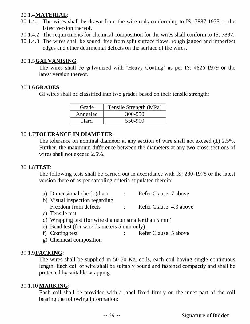
~ 69 ~ Signature of Bidder
30.1.4 MATERIAL:
30.1.4.1 The wires shall be drawn from the wire rods conforming to IS: 7887-1975 or the
latest version thereof.
30.1.4.2 The requirements for chemical composition for the wires shall conform to IS: 7887.
30.1.4.3 The wires shall be sound, free from split surface flaws, rough jagged and imperfect
edges and other detrimental defects on the surface of the wires.
30.1.5 GALVANISING:
The wires shall be galvanized with „Heavy Coating‟ as per IS: 4826-1979 or the
latest version thereof.
30.1.6 GRADES:
GI wires shall be classified into two grades based on their tensile strength:
Grade Tensile Strength (MPa)
Annealed 300-550
Hard 550-900
30.1.7 TOLERANCE IN DIAMETER:
The tolerance on nominal diameter at any section of wire shall not exceed (±) 2.5%.
Further, the maximum difference between the diameters at any two cross-sections of
wires shall not exceed 2.5%.
30.1.8 TEST:
The following tests shall be carried out in accordance with IS: 280-1978 or the latest
version there of as per sampling criteria stipulated therein:
a) Dimensional check (dia.) : Refer Clause: 7 above
b) Visual inspection regarding
Freedom from defects : Refer Clause: 4.3 above
c) Tensile test
d) Wrapping test (for wire diameter smaller than 5 mm)
e) Bend test (for wire diameters 5 mm only)
f) Coating test : Refer Clause: 5 above
g) Chemical composition
30.1.9 PACKING:
The wires shall be supplied in 50-70 Kg. coils, each coil having single continuous
length. Each coil of wire shall be suitably bound and fastened compactly and shall be
protected by suitable wrapping.
30.1.10 MARKING:
Each coil shall be provided with a label fixed firmly on the inner part of the coil
bearing the following information:
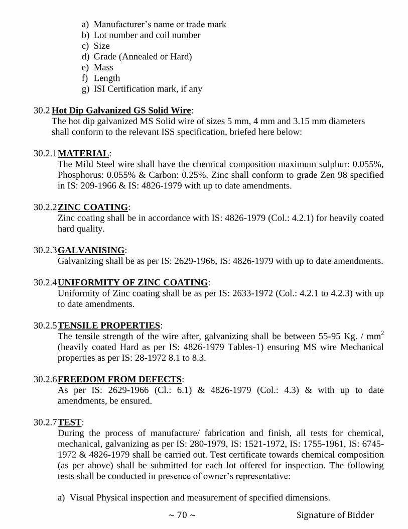
~ 70 ~ Signature of Bidder
a) Manufacturer‟s name or trade mark
b) Lot number and coil number
c) Size
d) Grade (Annealed or Hard)
e) Mass
f) Length
g) ISI Certification mark, if any
30.2 Hot Dip Galvanized GS Solid Wire:
The hot dip galvanized MS Solid wire of sizes 5 mm, 4 mm and 3.15 mm diameters
shall conform to the relevant ISS specification, briefed here below:
30.2.1 MATERIAL:
The Mild Steel wire shall have the chemical composition maximum sulphur: 0.055%,
Phosphorus: 0.055% & Carbon: 0.25%. Zinc shall conform to grade Zen 98 specified
in IS: 209-1966 & IS: 4826-1979 with up to date amendments.
30.2.2 ZINC COATING:
Zinc coating shall be in accordance with IS: 4826-1979 (Col.: 4.2.1) for heavily coated
hard quality.
30.2.3 GALVANISING:
Galvanizing shall be as per IS: 2629-1966, IS: 4826-1979 with up to date amendments.
30.2.4 UNIFORMITY OF ZINC COATING:
Uniformity of Zinc coating shall be as per IS: 2633-1972 (Col.: 4.2.1 to 4.2.3) with up
to date amendments.
30.2.5 TENSILE PROPERTIES:
The tensile strength of the wire after, galvanizing shall be between 55-95 Kg. / mm2
(heavily coated Hard as per IS: 4826-1979 Tables-1) ensuring MS wire Mechanical
properties as per IS: 28-1972 8.1 to 8.3.
30.2.6 FREEDOM FROM DEFECTS:
As per IS: 2629-1966 (Cl.: 6.1) & 4826-1979 (Col.: 4.3) & with up to date
amendments, be ensured.
30.2.7 TEST:
During the process of manufacture/ fabrication and finish, all tests for chemical,
mechanical, galvanizing as per IS: 280-1979, IS: 1521-1972, IS: 1755-1961, IS: 6745-
1972 & 4826-1979 shall be carried out. Test certificate towards chemical composition
(as per above) shall be submitted for each lot offered for inspection. The following
tests shall be conducted in presence of owner‟s representative:
a) Visual Physical inspection and measurement of specified dimensions.
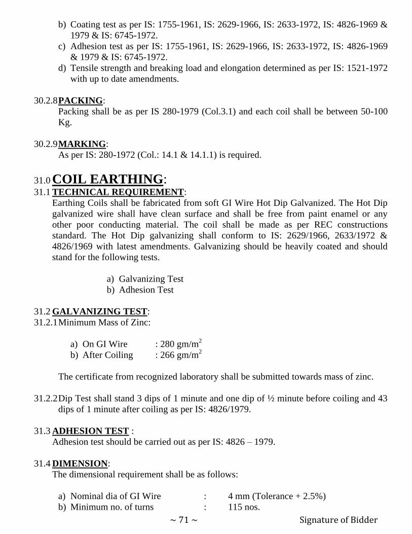
~ 71 ~ Signature of Bidder
b) Coating test as per IS: 1755-1961, IS: 2629-1966, IS: 2633-1972, IS: 4826-1969 &
1979 & IS: 6745-1972.
c) Adhesion test as per IS: 1755-1961, IS: 2629-1966, IS: 2633-1972, IS: 4826-1969
& 1979 & IS: 6745-1972.
d) Tensile strength and breaking load and elongation determined as per IS: 1521-1972
with up to date amendments.
30.2.8 PACKING:
Packing shall be as per IS 280-1979 (Col.3.1) and each coil shall be between 50-100
Kg.
30.2.9 MARKING:
As per IS: 280-1972 (Col.: 14.1 & 14.1.1) is required.
31.0 COIL EARTHING: 31.1 TECHNICAL REQUIREMENT:
Earthing Coils shall be fabricated from soft GI Wire Hot Dip Galvanized. The Hot Dip
galvanized wire shall have clean surface and shall be free from paint enamel or any
other poor conducting material. The coil shall be made as per REC constructions
standard. The Hot Dip galvanizing shall conform to IS: 2629/1966, 2633/1972 &
4826/1969 with latest amendments. Galvanizing should be heavily coated and should
stand for the following tests.
a) Galvanizing Test
b) Adhesion Test
31.2 GALVANIZING TEST:
31.2.1 Minimum Mass of Zinc:
a) On GI Wire : 280 gm/m2
b) After Coiling : 266 gm/m2
The certificate from recognized laboratory shall be submitted towards mass of zinc.
31.2.2 Dip Test shall stand 3 dips of 1 minute and one dip of ½ minute before coiling and 43
dips of 1 minute after coiling as per IS: 4826/1979.
31.3 ADHESION TEST :
Adhesion test should be carried out as per IS: 4826 – 1979.
31.4 DIMENSION:
The dimensional requirement shall be as follows:
a) Nominal dia of GI Wire : 4 mm (Tolerance + 2.5%)
b) Minimum no. of turns : 115 nos.

~ 72 ~ Signature of Bidder
c) External dia of Coil (Min) : 50 mm
d) Length of Coil (Min : 460 mm
e) Free length of
GI Wire at one end coil (Min.) : 2500 mm
f) The turns should be closely bound
g) Weight of one
Finished Earthing Coils (min.) : 1.850 Kg.
32.0 40 mm DIA 3 mtr. GI PIPE EARTHING: The scope of supply shall include design, engineering, manufacture, pre-delivery
inspection at your works, loading at your works, transit insurance, transportation,
supply/delivery & unloading at WESCO‟s Store/Site including guaranteed obligation of
complete supply of 40 mm dia 3 mtr. long GI Pipe Earthing as specified here under and
in conformity to the guaranteed technical particulars enclosed herewith.
33.0 CONTROL CABLE:
33.1 SCOPE & CONDITIONS:
This specification covers the testing and performance requirements of control cables for
installation on the Distribution System of WESCO.
The control cable offered shall have been successfully type tested and the design shall
have been in satisfactory operation for a period not less than preceding two years on the
date of bid opening. Compliance shall be demonstrated by submitting with the bid as
follows:
(i) Authenticated copies of the type test reports
(ii) Performance certificates from the users
The control cables shall conform in all respects to highest standards of
engineering, design, workmanship, this specification and the latest revisions of
relevant standards at the time of offer and the Engineer-In-charge shall have the
power to reject any work or material, which, in his judgment, is not in full accordance
therewith.
33.2 STANDARDS:
Except where modified by this specification, the control cables shall be designed,
manufactured and tested in accordance with the latest editions of the following
standards.
IEC / ISO Indian Standard Title
IEC: 811 IS: 18-10810: 1982 Testing cables
IEC: 502 IS: 7098: 1985 (Part: 2) LT and 3.3 – 33 KV XLPE cables
IS: 1554: 1988 (Part: 1) PVC Cables 0.65/1.1 KV
IS: 6474: 1984 XLPE Cables

~ 73 ~ Signature of Bidder
IEC: 502 Extruded solid dielectric insulated power cables for rated
voltages from 1.1 KV to 30 KV
IEC: 227 IS: 5819: 1970 Short circuit ratings for PVC cables
IEC: 228 IS: 15-8130: 1984 Conductors for insulated cables
IEC: 540 IS: 5831: 1984 Test Methods for insulation and sheaths of electric cables and
cords
IEC: 287 Calculation of the continuous current rating of cables
IS: 3975: 1979 Mild steel wires, strips and tapes for armouring of
cables
The Bidder may propose alternative standards, provided it is demonstrated that they
give a degree of quality and performance equivalent to or better than the referenced
standards. Acceptability of any alternative standard is at the discretion of the Project
Manager. The Bidder shall furnish a copy of the alternative standard proposed along
with his bid. If the alternative standard is in a language other than English, an English
translation shall be submitted with the standard. In the case of conflict the order of
precedence shall be:
a) IEC or ISO Standards
b) Indian Standards
c) Other alternative standards
This list is not to be considered exhaustive and reference to a particular standard
or recommendation in this Specification does not relieve the Contractor of the necessity
of providing the goods complying with other relevant standards or recommendations.
33.3 SERVICE CONDITIONS:
The service conditions shall be as follows:
Maximum altitude above sea level 1000 mtr.
Maximum ambient air temperature 50 C
Maximum daily average ambient air temperature 35 C
Maximum temperature attainable by an object exposed to the sun 60 C
maximum yearly weighted average ambient temperature 32 C
maximum relative humidity 100%
Average number of thunderstorm days per annum (Isokeraunic
level)
70
Average number of rainy days per annum 120
wind pressures as per IS: 802 (Part I/ Sec. l): 1995 150 cm
Environmentally, the region where the work will take place includes coastal
areas, subject to high relative humidity, which can give rise to condensation.
Onshore winds will frequently be salt laden. On occasions, the combination of salt and
condensation may create pollution conditions for outdoor insulators. Therefore, outdoor
material and equipment shall be designed and protected for use in exposed, heavily
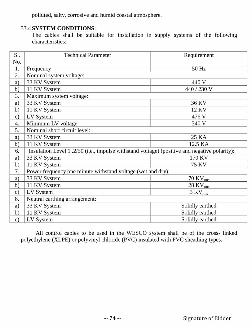
~ 74 ~ Signature of Bidder
polluted, salty, corrosive and humid coastal atmosphere.
33.4 SYSTEM CONDITIONS:
The cables shall be suitable for installation in supply systems of the following
characteristics:
Sl.
No.
Technical Parameter Requirement
1. Frequency 50 Hz
2. Nominal system voltage:
a) 33 KV System 440 V
b) 11 KV System 440 / 230 V
3. Maximum system voltage:
a) 33 KV System 36 KV
b) 11 KV System 12 KV
c) LV System 476 V
4. Minimum LV voltage 340 V
5. Nominal short circuit level:
a) 33 KV System 25 KA
b) 11 KV System 12.5 KA
6. Insulation Level 1 .2/50 (i.e., impulse withstand voltage) (positive and negative polarity):
a) 33 KV System 170 KV
b) 11 KV System 75 KV
7. Power frequency one minute withstand voltage (wet and dry):
a) 33 KV System 70 KVrms
b) 11 KV System 28 KVrms
c) LV System 3 KVrms
8. Neutral earthing arrangement:
a) 33 KV System Solidly earthed
b) 11 KV System Solidly earthed
c) LV System Solidly earthed
All control cables to be used in the WESCO system shall be of the cross- linked
polyethylene (XLPE) or polyvinyl chloride (PVC) insulated with PVC sheathing types.
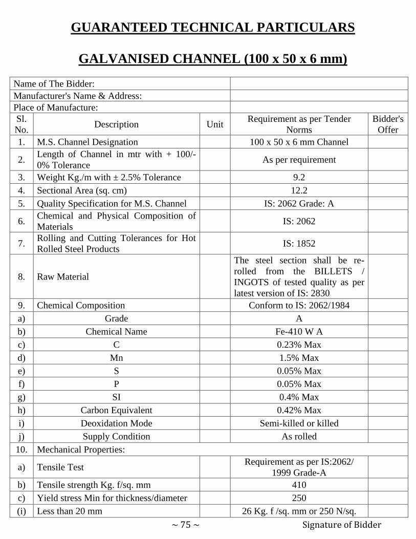
~ 75 ~ Signature of Bidder
GUARANTEED TECHNICAL PARTICULARS
GALVANISED CHANNEL (100 x 50 x 6 mm)
Name of The Bidder:
Manufacturer's Name & Address:
Place of Manufacture:
Sl.
No. Description Unit
Requirement as per Tender
Norms
Bidder's
Offer
1. M.S. Channel Designation
100 x 50 x 6 mm Channel
2. Length of Channel in mtr with + 100/-
0% Tolerance As per requirement
3. Weight Kg./m with ± 2.5% Tolerance
9.2
4. Sectional Area (sq. cm)
12.2
5. Quality Specification for M.S. Channel IS: 2062 Grade: A
6. Chemical and Physical Composition of
Materials IS: 2062
7. Rolling and Cutting Tolerances for Hot
Rolled Steel Products IS: 1852
8. Raw Material
The steel section shall be re-
rolled from the BILLETS /
INGOTS of tested quality as per
latest version of IS: 2830
9. Chemical Composition Conform to IS: 2062/1984
a) Grade
A
b) Chemical Name
Fe-410 W A
c) C 0.23% Max
d) Mn 1.5% Max
e) S 0.05% Max
f) P 0.05% Max
g) SI 0.4% Max
h) Carbon Equivalent
0.42% Max
i) Deoxidation Mode
Semi-killed or killed
j) Supply Condition
As rolled
10. Mechanical Properties:
a) Tensile Test
Requirement as per IS:2062/
1999 Grade-A
b) Tensile strength Kg. f/sq. mm 410
c) Yield stress Min for thickness/diameter 250
(i) Less than 20 mm 26 Kg. f /sq. mm or 250 N/sq.
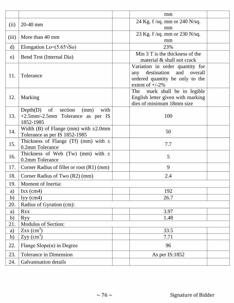
~ 76 ~ Signature of Bidder
mm
(ii) 20-40 mm 24 Kg. f /sq. mm or 240 N/sq.
mm
(iii) More than 40 mm 23 Kg. f /sq. mm or 230 N/sq.
mm
d) Elongation Lo=(5.65√So) 23%
e) Bend Test (Internal Dia) Min 3 T is the thickness of the
material & shall not crack
11. Tolerance
Variation in order quantity for
any destination and overall
ordered quantity be only to the
extent of +/-2%
12. Marking
The mark shall be in legible
English letter given with marking
dies of minimum 18mm size
13.
Depth(D) of section (mm) with
+2.5mm/-2.5mm Tolerance as per IS
1852-1985
100
14. Width (B) of Flange (mm) with ±2.0mm
Tolerance as per IS 1852-1985 50
15. Thickness of Flange (Tf) (mm) with ±
0.2mm Tolerance 7.7
16. Thickness of Web (Tw) (mm) with ±
0.2mm Tolerance 5
17. Corner Radius of fillet or root (R1) (mm) 9
18. Corner Radius of Two (R2) (mm) 2.4
19. Moment of Inertia:
a) Ixx (cm4) 192
b) Iyy (cm4) 26.7
20. Radius of Gyration (cm):
a) Rxx 3.97
b) Ryy 1.48
21. Modulus of Section:
a) Zxx (cm3) 33.5
b) Zyy (cm3) 7.71
22. Flange Slope(α) in Degree 96
23. Tolerance in Dimension As per IS:1852
24. Galvanisation details
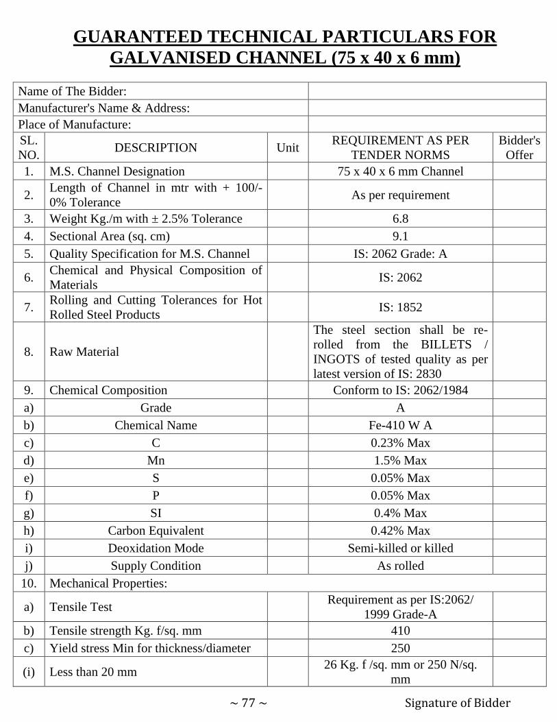
~ 77 ~ Signature of Bidder
GUARANTEED TECHNICAL PARTICULARS FOR
GALVANISED CHANNEL (75 x 40 x 6 mm)
Name of The Bidder:
Manufacturer's Name & Address:
Place of Manufacture:
SL.
NO. DESCRIPTION Unit
REQUIREMENT AS PER
TENDER NORMS
Bidder's
Offer
1. M.S. Channel Designation
75 x 40 x 6 mm Channel
2. Length of Channel in mtr with + 100/-
0% Tolerance As per requirement
3. Weight Kg./m with ± 2.5% Tolerance
6.8
4. Sectional Area (sq. cm)
9.1
5. Quality Specification for M.S. Channel IS: 2062 Grade: A
6. Chemical and Physical Composition of
Materials IS: 2062
7. Rolling and Cutting Tolerances for Hot
Rolled Steel Products IS: 1852
8. Raw Material
The steel section shall be re-
rolled from the BILLETS /
INGOTS of tested quality as per
latest version of IS: 2830
9. Chemical Composition Conform to IS: 2062/1984
a) Grade
A
b) Chemical Name
Fe-410 W A
c) C 0.23% Max
d) Mn 1.5% Max
e) S 0.05% Max
f) P 0.05% Max
g) SI 0.4% Max
h) Carbon Equivalent
0.42% Max
i) Deoxidation Mode
Semi-killed or killed
j) Supply Condition
As rolled
10. Mechanical Properties:
a) Tensile Test
Requirement as per IS:2062/
1999 Grade-A
b) Tensile strength Kg. f/sq. mm 410
c) Yield stress Min for thickness/diameter 250
(i) Less than 20 mm 26 Kg. f /sq. mm or 250 N/sq.
mm

~ 78 ~ Signature of Bidder
(ii) 20-40 mm 24 Kg. f /sq. mm or 240 N/sq.
mm
(iii) More than 40 mm 23 Kg. f /sq. mm or 230 N/sq.
mm
d) Elongation Lo=(5.65√So) 23%
e) Bend Test (Internal Dia) Min 3 T is the thickness of the
material & shall not crack
11. Tolerance
Variation in order quantity for
any destination and overall
ordered quantity be only to the
extent of +/-2%
12. Marking
The mark shall be in legible
English letter given with marking
dies of minimum 18mm size
13.
Depth(D) of section (mm) with
+2.5mm/-2.5mm Tolerance as per IS
1852-1985
75
14. Width (B) of Flange (mm) with ±2.0mm
Tolerance as per IS 1852-1985. 40
15. Thickness of Flange (Tf) (mm) with
±0.2mm Tolerance. 7.5
16. Thickness of Web (Tw) (mm) with
±0.2mm Tolerance. 4.8
17. Corner Radius of fillet or root (R1) (mm) 8.5
18. Corner Radius of Two (R2) (mm) 2.4
19. Moment of Inertia:
a) Ixx (cm4) 78.5
b) Iyy (cm4) 12.9
20. Radius of Gyration (cm):
a) Rxx 2.94
b) Ryy 1.19
21. Modulus of Section:
a) Zxx(cm3) 20.9
b) Zyy(cm3) 4.81
22. Flange Slope(α) in Degree 96
23. Tolerance in Dimension As per IS:1852
24. Galvanisation Details

~ 79 ~ Signature of Bidder
GUARANTEED TECHNICAL PARTICULARS FOR
GALVANISED ANGLE (50 x 50 x 6 mm)
Name of The Bidder:
Manufacturer's Name & Address:
Place of Manufacture:
SL.
NO. DESCRIPTION Unit
REQUIREMENT AS PER TENDER
NORMS
Bidder's
Offer
1. M.S. Angle Designation
50 x 50 x 6 mm
2. Quality Specification for M.S Angle IS: 2062 Grade A
3. Chemical and Physical Composition
of Materials IS: 2062
4. Rolling and Cutting Tolerances for
Hot Rolled Steel Products IS: 1852
5. Raw Material
The steel section shall be re-rolled from
the BILLETS/INGOTS of tested
quality as per latest version of IS: 2830
6. Chemical Composition Conform to IS: 2062/1984 &
IS:2062/1999 Grade-A
a) Grade
A
b) Chemical Name
Fe-410W A
c) C 0.23% Max
d) Mn 1.5% Max
e) S 0.05% Max
f) P 0.05% Max
g) SI 0.4% Max
h) Carbon Equivalent (%Max.)
0.42
i) De-oxidation Mode
Semi-killed or killed
7. Mechanical Properties:
a) Tensile strength Kg. f/sq mm 410 as per IS:2062/ 1999 Grade-A
b) Yield stress Min for thickness/diameter:
(i) Less than 20 mm 26 Kg. f /sq. mm or 250 N/sq. mm
(ii) 20-40 mm 24 Kg. f /sq. mm or 240 N/sq. mm
(iii) More than 40 mm 23 Kg. f /sq. mm or 230 N/sq. mm
c) Elongation (min.) (LO = 5.65√SO) 23%
d) Bend Test (Internal Dia) Min 3 T is the thickness of the material
& shall not crack
8. Tolerance
Variation in order quantity for any
destination and overall ordered quantity
be only to the extent of +/-2%
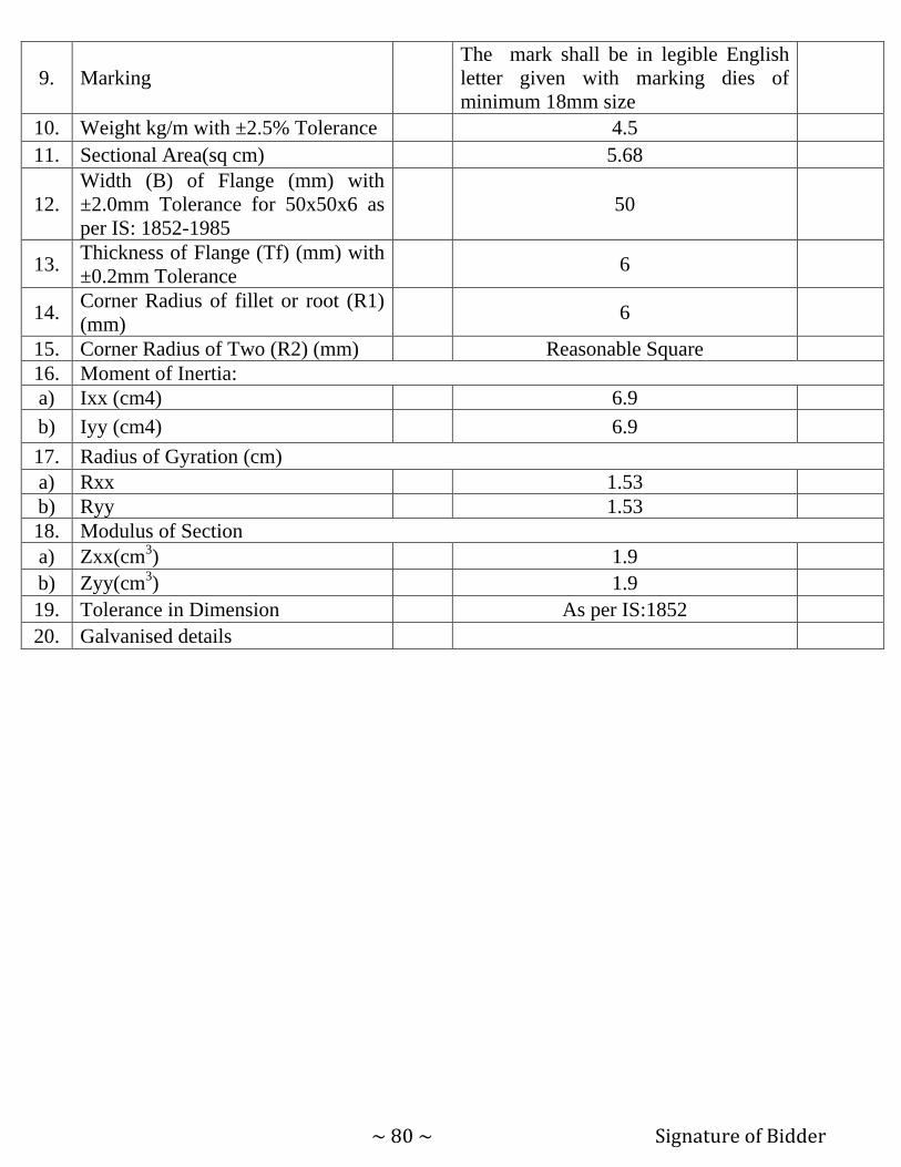
~ 80 ~ Signature of Bidder
9. Marking
The mark shall be in legible English
letter given with marking dies of
minimum 18mm size
10. Weight kg/m with ±2.5% Tolerance 4.5
11. Sectional Area(sq cm) 5.68
12.
Width (B) of Flange (mm) with
±2.0mm Tolerance for 50x50x6 as
per IS: 1852-1985
50
13. Thickness of Flange (Tf) (mm) with
±0.2mm Tolerance 6
14. Corner Radius of fillet or root (R1)
(mm) 6
15. Corner Radius of Two (R2) (mm) Reasonable Square
16. Moment of Inertia:
a) Ixx (cm4) 6.9
b) Iyy (cm4) 6.9
17. Radius of Gyration (cm)
a) Rxx 1.53
b) Ryy 1.53
18. Modulus of Section
a) Zxx(cm3) 1.9
b) Zyy(cm3) 1.9
19. Tolerance in Dimension As per IS:1852
20. Galvanised details
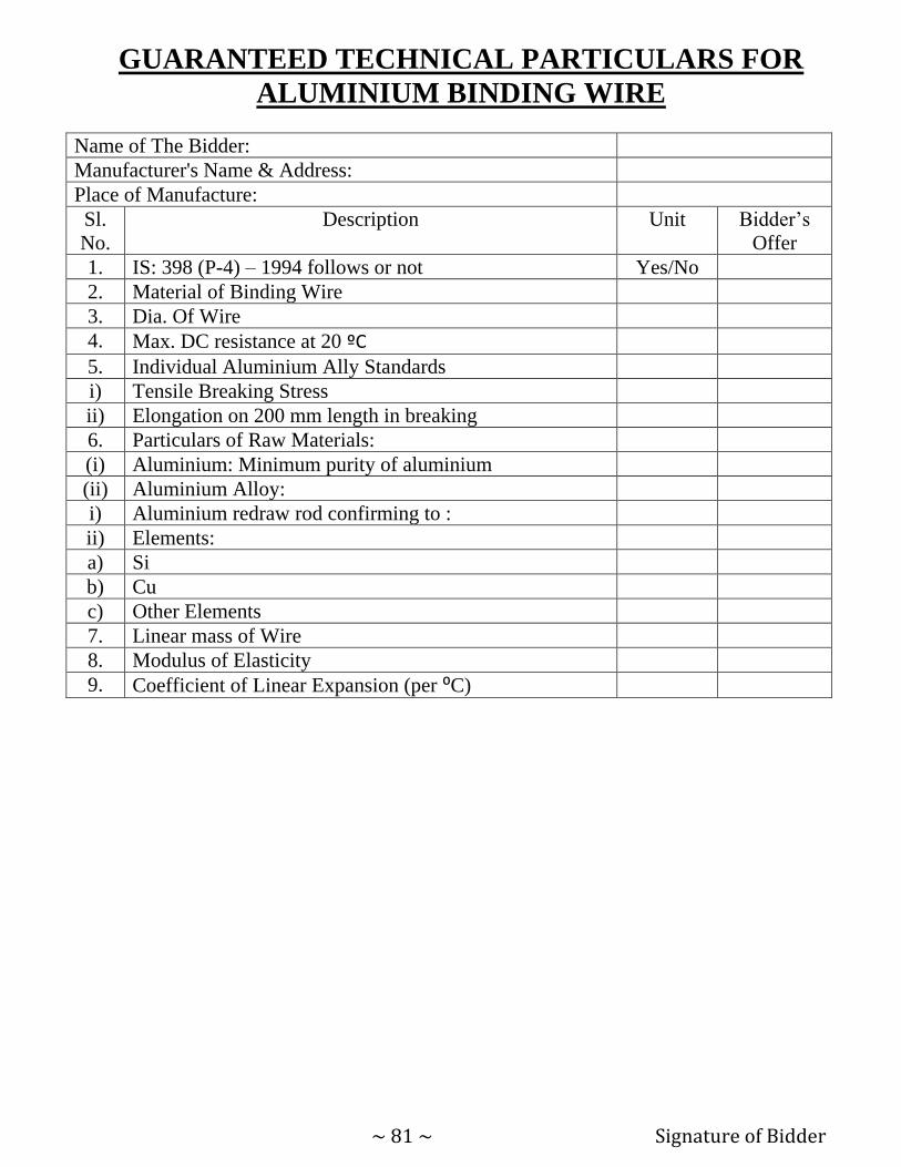
~ 81 ~ Signature of Bidder
GUARANTEED TECHNICAL PARTICULARS FOR
ALUMINIUM BINDING WIRE
Name of The Bidder:
Manufacturer's Name & Address:
Place of Manufacture:
Sl.
No.
Description Unit Bidder‟s
Offer
1. IS: 398 (P-4) – 1994 follows or not Yes/No
2. Material of Binding Wire
3. Dia. Of Wire
4. Max. DC resistance at 20 ºC
5. Individual Aluminium Ally Standards
i) Tensile Breaking Stress
ii) Elongation on 200 mm length in breaking
6. Particulars of Raw Materials:
(i) Aluminium: Minimum purity of aluminium
(ii) Aluminium Alloy:
i) Aluminium redraw rod confirming to :
ii) Elements:
a) Si
b) Cu
c) Other Elements
7. Linear mass of Wire
8. Modulus of Elasticity
9. Coefficient of Linear Expansion (per ⁰C)

~ 82 ~ Signature of Bidder
GUARANTEED TECHNICAL PARTICULARS FOR
33 KV 1250 AMPERE ISOLATOR WITH EARTHSWITCH
(WITHOUT MOTOR)
Name of the Bidder:
Name of Manufacturer:
Place of Manufacture
Sl.
No.
Technical Particulars Units Requirement Bidder‟s
Offer
1. Rated Frequency Hz 50
2. No. of Phase (Pole) No. 3
3. Temperature Rise ºC As per relevant
IS/IEC
4. Safe duration of overload:
a) At 150% of rated current Minutes 5
b) At 120% of rated current Minutes 30
5) Rated Nominal Voltage KV 33
6) Highest System Voltage KVrms 36
7) Type of Discount
8) Rated normal current Amp. 1250
9) Rated short time withstand current main switch for 3 sec KArms 25
10) Rated peak current of main switch KAPeak 62.5
11) Basic Insulation Level:
(i) Lightning Impulse Withstand Voltage:
a) To earth and between poles KVPeak 170
b) Across Isolating Distance KVPeak 195
(ii) Rated Power Frequency Withstand Voltage:
a) To earth and between poles KVrms 70
b) Across Isolating Distance KVrms 80
12) Minimum Creepage mm 900
13) Centre to centre spacing for installation mm
14) Minimum Clearance:
a) Phase to earth mm
b) Between the rotating post and fixed post on one phase mm
15) Height of centre line of terminal pad above ground level mm
16) Special Requirement:
a) Isolating main switch shall be required to make or break
the line charging current when no significant change in
voltage occurs across the isolating distance on account
of make or break
Yes/No
b) The isolator required is not with turn and twist
mechanism. It must be of rotating type
Yes/No
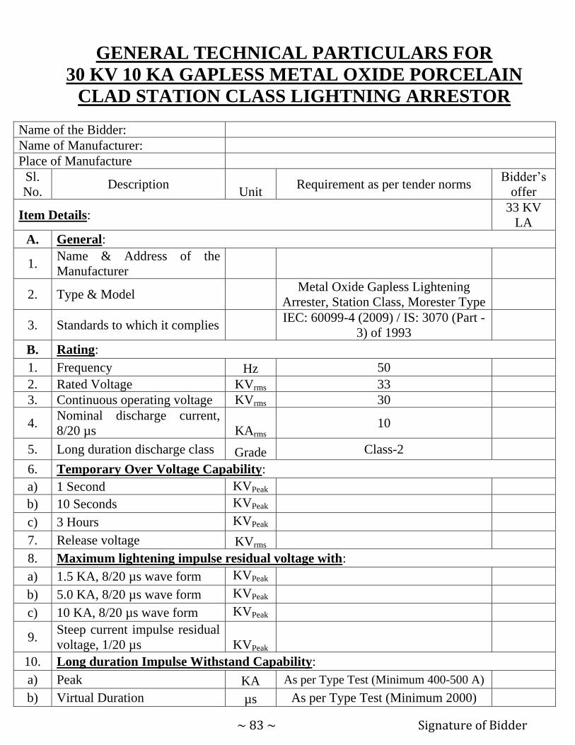
~ 83 ~ Signature of Bidder
GENERAL TECHNICAL PARTICULARS FOR
30 KV 10 KA GAPLESS METAL OXIDE PORCELAIN
CLAD STATION CLASS LIGHTNING ARRESTOR
Name of the Bidder:
Name of Manufacturer:
Place of Manufacture
Sl.
No. Description
Unit Requirement as per tender norms
Bidder‟s
offer
Item Details: 33 KV
LA
A. General:
1. Name & Address of the
Manufacturer
2. Type & Model
Metal Oxide Gapless Lightening
Arrester, Station Class, Morester Type
3. Standards to which it complies
IEC: 60099-4 (2009) / IS: 3070 (Part -
3) of 1993
B. Rating:
1. Frequency Hz 50
2. Rated Voltage KVrms 33
3. Continuous operating voltage KVrms 30
4. Nominal discharge current,
8/20 µs KArms 10
5. Long duration discharge class Grade Class-2
6. Temporary Over Voltage Capability:
a) 1 Second KVPeak
b) 10 Seconds KVPeak
c) 3 Hours KVPeak
7. Release voltage KVrms 8. Maximum lightening impulse residual voltage with:
a) 1.5 KA, 8/20 µs wave form KVPeak
b) 5.0 KA, 8/20 µs wave form KVPeak
c) 10 KA, 8/20 µs wave form KVPeak
9. Steep current impulse residual
voltage, 1/20 µs KVPeak
10. Long duration Impulse Withstand Capability:
a) Peak KA As per Type Test (Minimum 400-500 A)
b) Virtual Duration µs As per Type Test (Minimum 2000)
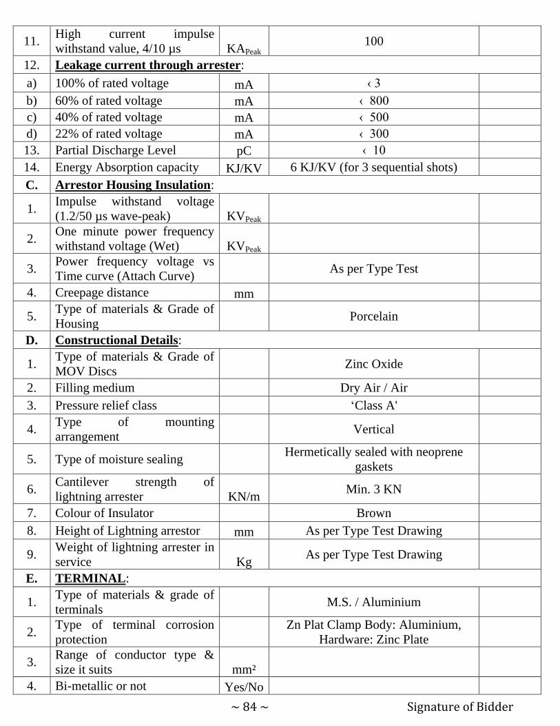
~ 84 ~ Signature of Bidder
11. High current impulse
withstand value, 4/10 µs KAPeak 100
12. Leakage current through arrester:
a) 100% of rated voltage mA ‹ 3
b) 60% of rated voltage mA ‹ 800
c) 40% of rated voltage mA ‹ 500
d) 22% of rated voltage mA ‹ 300
13. Partial Discharge Level pC ‹ 10
14. Energy Absorption capacity KJ/KV 6 KJ/KV (for 3 sequential shots)
C. Arrestor Housing Insulation:
1. Impulse withstand voltage
(1.2/50 µs wave-peak) KVPeak
2. One minute power frequency
withstand voltage (Wet) KVPeak
3. Power frequency voltage vs
Time curve (Attach Curve)
As per Type Test
4. Creepage distance mm
5. Type of materials & Grade of
Housing
Porcelain
D. Constructional Details:
1. Type of materials & Grade of
MOV Discs
Zinc Oxide
2. Filling medium
Dry Air / Air
3. Pressure relief class
„Class A'
4. Type of mounting
arrangement
Vertical
5. Type of moisture sealing
Hermetically sealed with neoprene
gaskets
6. Cantilever strength of
lightning arrester KN/m Min. 3 KN
7. Colour of Insulator
Brown
8. Height of Lightning arrestor mm As per Type Test Drawing
9. Weight of lightning arrester in
service Kg As per Type Test Drawing
E. TERMINAL:
1. Type of materials & grade of
terminals
M.S. / Aluminium
2. Type of terminal corrosion
protection
Zn Plat Clamp Body: Aluminium,
Hardware: Zinc Plate
3. Range of conductor type &
size it suits mm²
4. Bi-metallic or not Yes/No
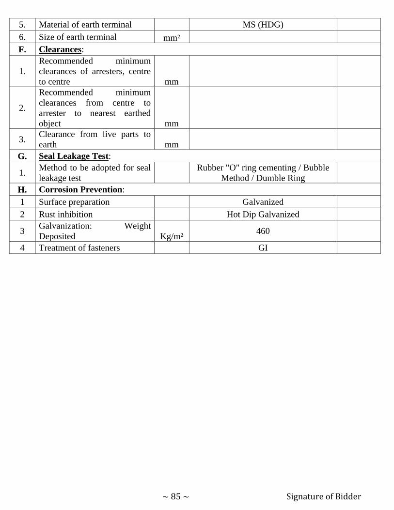
~ 85 ~ Signature of Bidder
5. Material of earth terminal
MS (HDG)
6. Size of earth terminal mm²
F. Clearances:
1.
Recommended minimum
clearances of arresters, centre
to centre mm
2.
Recommended minimum
clearances from centre to
arrester to nearest earthed
object mm
3. Clearance from live parts to
earth mm
G. Seal Leakage Test:
1. Method to be adopted for seal
leakage test
Rubber "O" ring cementing / Bubble
Method / Dumble Ring
H. Corrosion Prevention:
1 Surface preparation
Galvanized
2 Rust inhibition
Hot Dip Galvanized
3 Galvanization: Weight
Deposited Kg/m² 460
4 Treatment of fasteners
GI
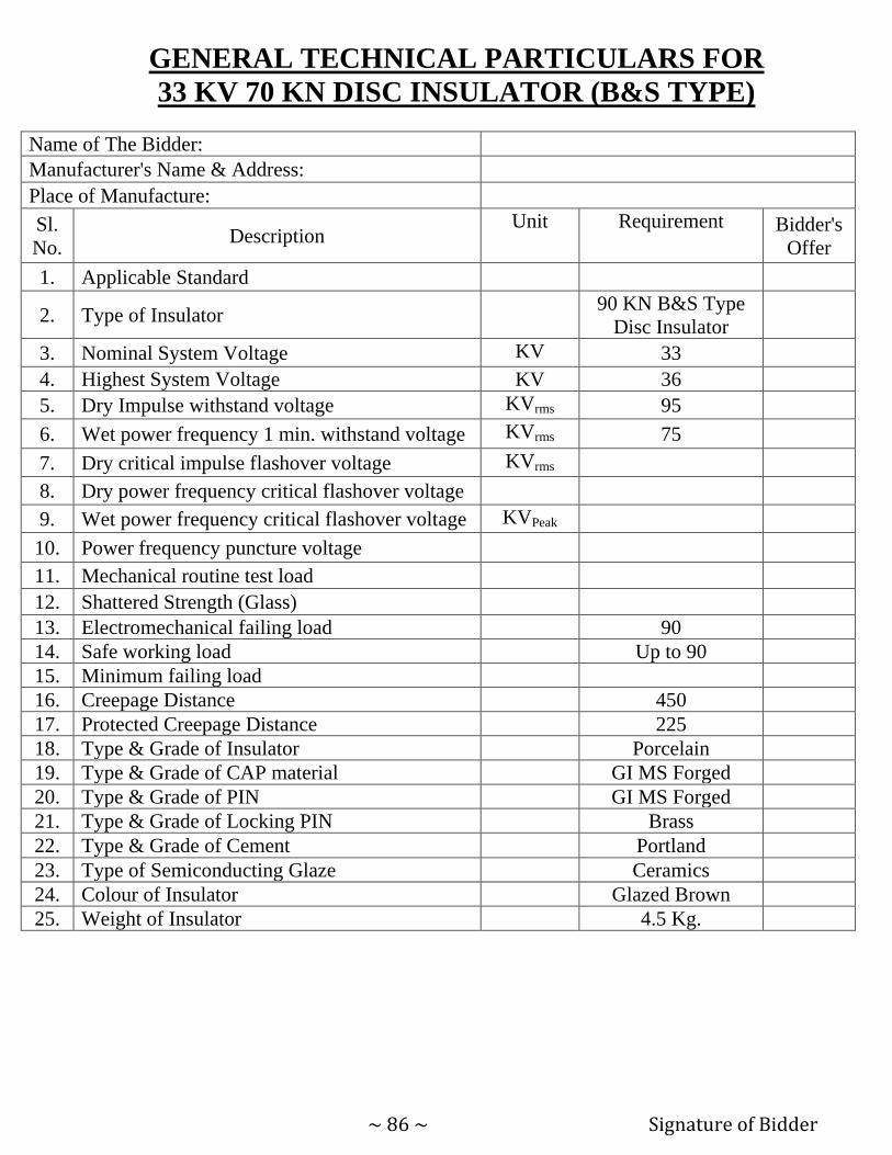
~ 86 ~ Signature of Bidder
GENERAL TECHNICAL PARTICULARS FOR
33 KV 70 KN DISC INSULATOR (B&S TYPE)
Name of The Bidder:
Manufacturer's Name & Address:
Place of Manufacture:
Sl.
No. Description
Unit Requirement Bidder's
Offer
1. Applicable Standard
2. Type of Insulator 90 KN B&S Type
Disc Insulator
3. Nominal System Voltage KV 33
4. Highest System Voltage KV 36
5. Dry Impulse withstand voltage KVrms 95
6. Wet power frequency 1 min. withstand voltage KVrms 75
7. Dry critical impulse flashover voltage KVrms
8. Dry power frequency critical flashover voltage
9. Wet power frequency critical flashover voltage KVPeak
10. Power frequency puncture voltage
11. Mechanical routine test load
12. Shattered Strength (Glass)
13. Electromechanical failing load 90
14. Safe working load Up to 90
15. Minimum failing load
16. Creepage Distance 450
17. Protected Creepage Distance 225
18. Type & Grade of Insulator Porcelain
19. Type & Grade of CAP material GI MS Forged
20. Type & Grade of PIN GI MS Forged
21. Type & Grade of Locking PIN Brass
22. Type & Grade of Cement Portland
23. Type of Semiconducting Glaze Ceramics
24. Colour of Insulator Glazed Brown
25. Weight of Insulator 4.5 Kg.
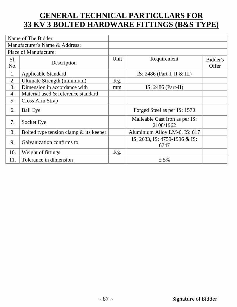
~ 87 ~ Signature of Bidder
GENERAL TECHNICAL PARTICULARS FOR
33 KV 3 BOLTED HARDWARE FITTINGS (B&S TYPE)
Name of The Bidder:
Manufacturer's Name & Address:
Place of Manufacture:
Sl.
No. Description
Unit Requirement Bidder's
Offer
1. Applicable Standard IS: 2486 (Part-I, II & III)
2. Ultimate Strength (minimum) Kg.
3. Dimension in accordance with mm IS: 2486 (Part-II)
4. Material used & reference standard
5. Cross Arm Strap
6. Ball Eye Forged Steel as per IS: 1570
7. Socket Eye Malleable Cast Iron as per IS:
2108/1962
8. Bolted type tension clamp & its keeper Aluminium Alloy LM-6, IS: 617
9. Galvanization confirms to IS: 2633, IS: 4759-1996 & IS:
6747
10. Weight of fittings Kg.
11. Tolerance in dimension ± 5%
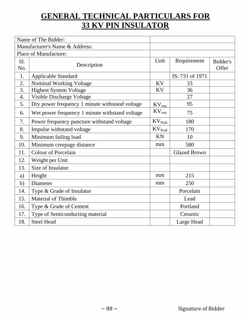
~ 88 ~ Signature of Bidder
GENERAL TECHNICAL PARTICULARS FOR
33 KV PIN INSULATOR
Name of The Bidder:
Manufacturer's Name & Address:
Place of Manufacture:
Sl.
No. Description
Unit Requirement Bidder's
Offer
1. Applicable Standard IS: 731 of 1971
2. Nominal Working Voltage KV 33
3. Highest System Voltage KV 36
4. Visible Discharge Voltage 27
5. Dry power frequency 1 minute withstand voltage KVrms 95
6. Wet power frequency 1 minute withstand voltage KVrms 75
7. Power frequency puncture withstand voltage KVPeak 180
8. Impulse withstand voltage KVPeak 170
9. Minimum failing load KN 10
10. Minimum creepage distance mm 580
11. Colour of Porcelain Glazed Brown
12. Weight per Unit
13. Size of Insulator
a) Height mm 215
b) Diameter mm 250
14. Type & Grade of Insulator Porcelain
15. Material of Thimble Lead
16. Type & Grade of Cement Portland
17. Type of Semiconducting material Ceramic
18. Steel Head Large Head
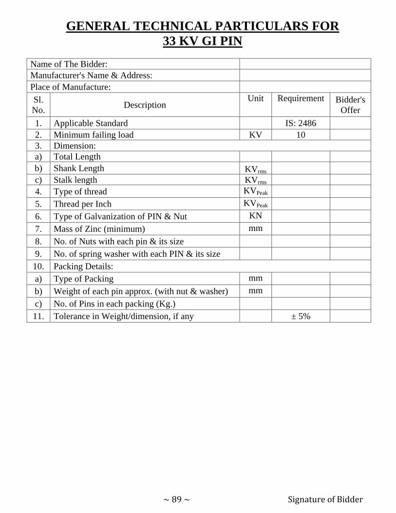
~ 89 ~ Signature of Bidder
GENERAL TECHNICAL PARTICULARS FOR
33 KV GI PIN
Name of The Bidder:
Manufacturer's Name & Address:
Place of Manufacture:
Sl.
No. Description
Unit Requirement Bidder's
Offer
1. Applicable Standard IS: 2486
2. Minimum failing load KV 10
3. Dimension:
a) Total Length
b) Shank Length KVrms
c) Stalk length KVrms
4. Type of thread KVPeak
5. Thread per Inch KVPeak
6. Type of Galvanization of PIN & Nut KN
7. Mass of Zinc (minimum) mm
8. No. of Nuts with each pin & its size
9. No. of spring washer with each PIN & its size
10. Packing Details:
a) Type of Packing mm
b) Weight of each pin approx. (with nut & washer) mm
c) No. of Pins in each packing (Kg.)
11. Tolerance in Weight/dimension, if any ± 5%
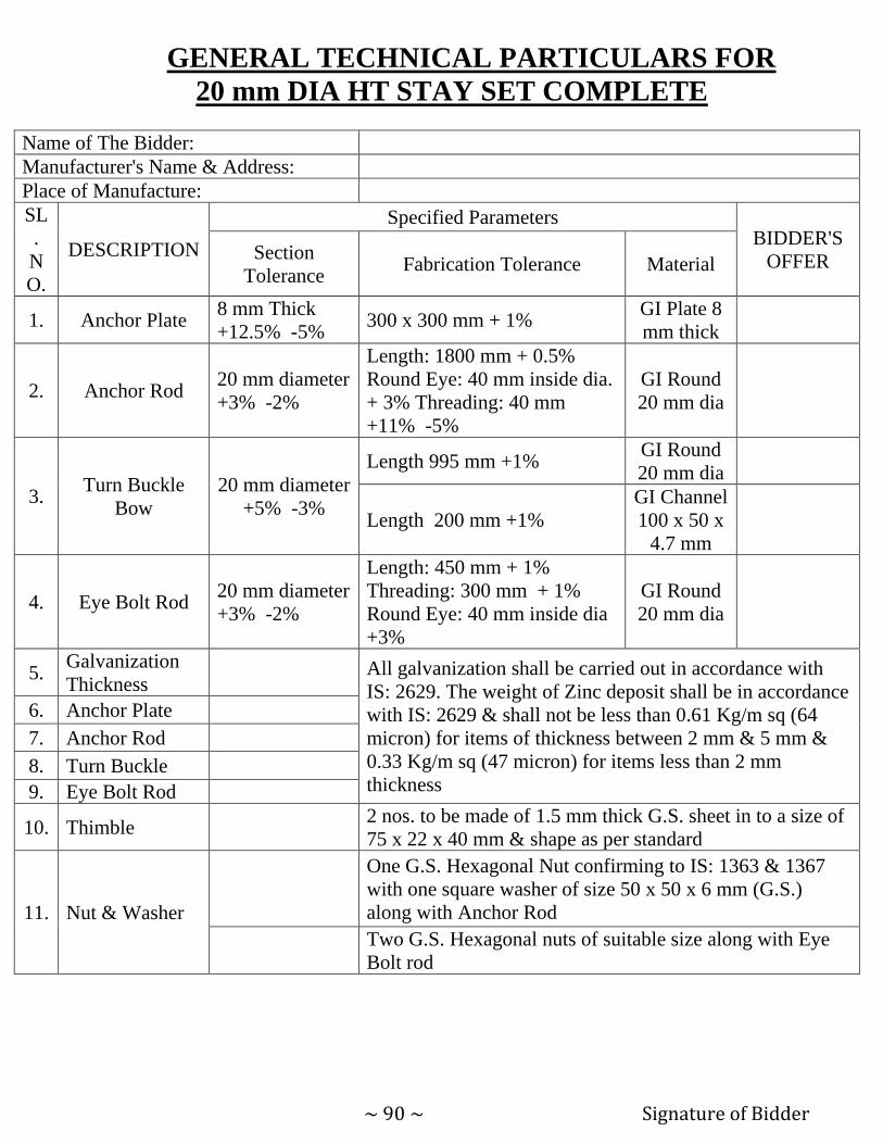
~ 90 ~ Signature of Bidder
GENERAL TECHNICAL PARTICULARS FOR
20 mm DIA HT STAY SET COMPLETE
Name of The Bidder:
Manufacturer's Name & Address:
Place of Manufacture:
SL
.
N
O.
DESCRIPTION
Specified Parameters BIDDER'S
OFFER Section
Tolerance Fabrication Tolerance Material
1. Anchor Plate 8 mm Thick
+12.5% -5% 300 x 300 mm + 1%
GI Plate 8
mm thick
2. Anchor Rod 20 mm diameter
+3% -2%
Length: 1800 mm + 0.5%
Round Eye: 40 mm inside dia.
+ 3% Threading: 40 mm
+11% -5%
GI Round
20 mm dia
3. Turn Buckle
Bow
20 mm diameter
+5% -3%
Length 995 mm +1% GI Round
20 mm dia
Length 200 mm +1%
GI Channel
100 x 50 x
4.7 mm
4. Eye Bolt Rod 20 mm diameter
+3% -2%
Length: 450 mm + 1%
Threading: 300 mm + 1%
Round Eye: 40 mm inside dia
+3%
GI Round
20 mm dia
5. Galvanization
Thickness All galvanization shall be carried out in accordance with
IS: 2629. The weight of Zinc deposit shall be in accordance
with IS: 2629 & shall not be less than 0.61 Kg/m sq (64
micron) for items of thickness between 2 mm & 5 mm &
0.33 Kg/m sq (47 micron) for items less than 2 mm
thickness
6. Anchor Plate
7. Anchor Rod
8. Turn Buckle
9. Eye Bolt Rod
10. Thimble 2 nos. to be made of 1.5 mm thick G.S. sheet in to a size of
75 x 22 x 40 mm & shape as per standard
11. Nut & Washer
One G.S. Hexagonal Nut confirming to IS: 1363 & 1367
with one square washer of size 50 x 50 x 6 mm (G.S.)
along with Anchor Rod
Two G.S. Hexagonal nuts of suitable size along with Eye
Bolt rod
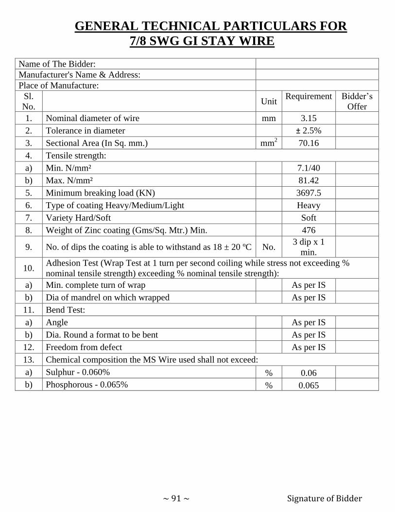
~ 91 ~ Signature of Bidder
GENERAL TECHNICAL PARTICULARS FOR
7/8 SWG GI STAY WIRE
Name of The Bidder:
Manufacturer's Name & Address:
Place of Manufacture:
Sl.
No. Unit
Requirement Bidder‟s
Offer
1. Nominal diameter of wire mm 3.15
2. Tolerance in diameter
± 2.5%
3. Sectional Area (In Sq. mm.) mm2 70.16
4. Tensile strength:
a) Min. N/mm²
7.1/40
b) Max. N/mm²
81.42
5. Minimum breaking load (KN)
3697.5
6. Type of coating Heavy/Medium/Light
Heavy
7. Variety Hard/Soft
Soft
8. Weight of Zinc coating (Gms/Sq. Mtr.) Min.
476
9. No. of dips the coating is able to withstand as 18 ± 20 ºC No. 3 dip x 1
min.
10. Adhesion Test (Wrap Test at 1 turn per second coiling while stress not exceeding %
nominal tensile strength) exceeding % nominal tensile strength):
a) Min. complete turn of wrap
As per IS
b) Dia of mandrel on which wrapped
As per IS
11. Bend Test:
a) Angle
As per IS
b) Dia. Round a format to be bent
As per IS
12. Freedom from defect
As per IS
13. Chemical composition the MS Wire used shall not exceed:
a) Sulphur - 0.060% % 0.06
b) Phosphorous - 0.065% % 0.065
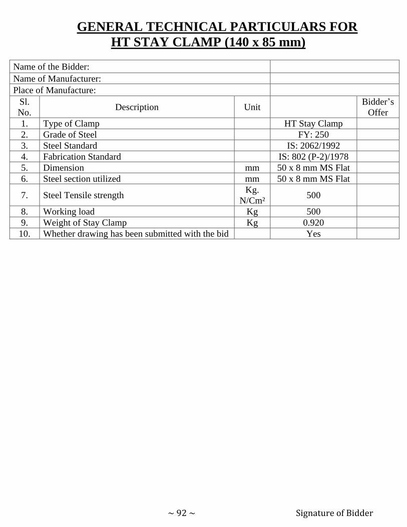
~ 92 ~ Signature of Bidder
GENERAL TECHNICAL PARTICULARS FOR
HT STAY CLAMP (140 x 85 mm)
Name of the Bidder:
Name of Manufacturer:
Place of Manufacture:
Sl.
No. Description Unit
Bidder‟s
Offer
1. Type of Clamp HT Stay Clamp
2. Grade of Steel FY: 250
3. Steel Standard IS: 2062/1992
4. Fabrication Standard IS: 802 (P-2)/1978
5. Dimension mm 50 x 8 mm MS Flat
6. Steel section utilized mm 50 x 8 mm MS Flat
7. Steel Tensile strength Kg.
N/Cm² 500
8. Working load Kg 500
9. Weight of Stay Clamp Kg 0.920
10. Whether drawing has been submitted with the bid Yes

~ 93 ~ Signature of Bidder
GENERAL TECHNICAL PARTICULARS FOR
HT STAY INSULATOR
Name of the Bidder:
Name of Manufacturer:
Place of Manufacture:
Sl.
No. Description Unit
Bidder‟s
Offer
1 Type of Insulator HT Stay Insulator
2 Applicable standard
3 Type of insulator (Porcelain or toughened glass)
4 Dry impulse withstand voltage
5 Wet power frequency, 1 minute, withstand voltage
6 Dry, Critical Impulse Flashover Voltage
7 Dry, power frequency, Critical Flashover Voltage
8 Wet, power frequency, Critical Flashover Voltage
9 Power frequency Puncture Voltage
10 Safe Working Load
11 Minimum Failing Load
12 Creepage Distance
13 Protected Creepage Distance
14 Type and Grade of Materials : Insulator
15 Colour of Insulator
16 Weight of Insulator
17 Number of Insulators per Crate
18 Type of semi-conducting glaze
19 Minimum dia of Stay wire hole
20
Gross Weight of Loaded Crate Whether drawing
showing dimensional details have been furnished
along with Bid
21 Whether Type Test Certificates have been furnished
22 Other particulars (if any)

~ 94 ~ Signature of Bidder
GENERAL TECHNICAL PARTICULARS FOR
GI COIL EARTHING
Name of the Bidder:
Name of Manufacturer:
Place of Manufacture:
Sl.
No. Description
Requirement Bidder's
Offer
1 Nominal diameter of wire mm 4 (8 SWG)
2 No. of Turns No. 115
3 External dia. Of coil mm 50
4 Length of Coil mm 460
5 Free length of GI wire at one end coil mm 2500
6 Mass of Zinc Gm/m² 266
7 Total weight of Coil Kg. 1.850

~ 95 ~ Signature of Bidder
GENERAL TECHNICAL PARTICULARS FOR
40 mm DIA GI PIPE EARTHING
Name of The Bidder:
Manufacturer's Name & Address:
Place of Manufacture:
Sl.
No. Description Unit
Requirement Bidder's
Offer
1 Type of Pipe
40 mm dia GI Pipe
Earthing
2 Size of:
a) Pipe mm 40 mm N.B.
b) Earthing Strips
N.A.
3 Length mtr. 3 mtr.
4 Thickness of Pipe mm 3.2 mm
5 Galvanization Process
IS: 2629/85
6 Galvanization thickness:
a) For Earthing device micron 86
b) For Connecting No. 6 SWG Wire
N.A.
7 Galvanization tests to be conducted as per ISS
IS: 2633
8 Any other Particulars ( like details of Clamp/ G.I. Bolts)
50 mm width 6 mm
thickness 65 mm
flange each side
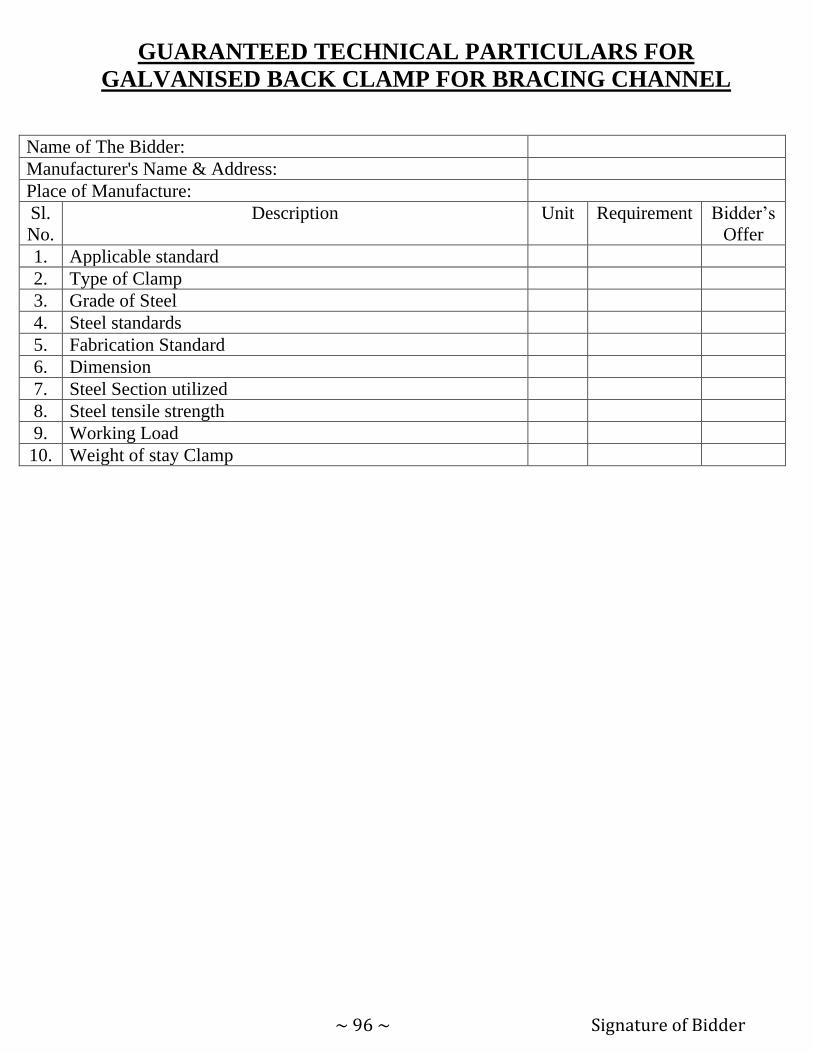
~ 96 ~ Signature of Bidder
GUARANTEED TECHNICAL PARTICULARS FOR
GALVANISED BACK CLAMP FOR BRACING CHANNEL
Name of The Bidder:
Manufacturer's Name & Address:
Place of Manufacture:
Sl.
No.
Description Unit Requirement Bidder‟s
Offer
1. Applicable standard
2. Type of Clamp
3. Grade of Steel
4. Steel standards
5. Fabrication Standard
6. Dimension
7. Steel Section utilized
8. Steel tensile strength
9. Working Load
10. Weight of stay Clamp

~ 97 ~ Signature of Bidder
GUARANTEED TECHNICAL PARTICULARS FOR
10 CORE x 2.5 mm2 LT CONTROL CABLE
Name of The Bidder:
Manufacturer's Name & Address:
Place of Manufacture:
SL.
No. Particulars Unit Requirement
Bidder‟s
Offer
1. Type of Cable
10 C x 2.5 mm2
2. Standard applicable
IS: 1554 (Part-I) / 1988
3. ISI Mark Details With Validity Period
4. Rated Voltage
1100 V
5. Suitable for Earth or Unearthed
Earthed
6. Continuous Current rating at an ambient temp:
a) 40 ºC
15
b) 70 ºC
7. Current Carrying Capacity:
a) Short Circuit Current
0.288
b) Duration of short circuit
1 Sec
c) Conductor temp. allowed for short circuit
160
8. Conductor Details :
a) Materials
E.C. Annealed Copper
Wire Class: 1 of IS:
8130/1984
b) Nominal Cross Sectional Area of conductor
2.5
c) Average dia of Copper conductor in mm
1.78
d) Conductor Resistance /Km at 20 ºC
7.41
9. Insulation Details:
a) Type
PVC, Type: A of IS:
5831/84
b) Thickness
0.9
c) Tolerance In Thickness
0.2
10. Colour Scheme for identification
As per IS: 15549 (Part-
I)/1988
11. Inner Sheath Details:
a) Materials
PVC
b) Extruded / Wrapped
Extruded
c) Calculated Dia over laid up cores
14.4
d) Thickness
0.3 min.
12. Armour:

~ 98 ~ Signature of Bidder
a) Type of armour
G.S Flat Strips
b) Nominal Dia over inner sheath
15
c) Nominal thickness of steel strip/dia of wire
1.4
13. Outer Sheath:
a) Materials
Black PVC Type –ST: 1
of IS: 5831/1988
b) Extruded / Wrapped
Extruded
c) Calculated diameter under sheath
18.2 mm
d) Thickness
1.4
e) Tolerance in thickness
0.2
14. Overall dia Cable
23.0 ± 2 mm
15. Volume resistivity at 27 º C and 70 º C
1 x 10¹³ at 27 ºC & 1 x
10¹º at 70 ºC
16. Test Voltage
a) High Voltage
3 KV for 5 min.
b) Water Immersion test voltage
1.2 KV (D.C) for 10 Days
17. Recommended Minimum installation Radius
12 x O.D.
18. Maximum length of cable per drum
1000 ± 5%
19. The Weight of Drum
130 Kg.
20. Net Weight of Cable Kg./Km
710
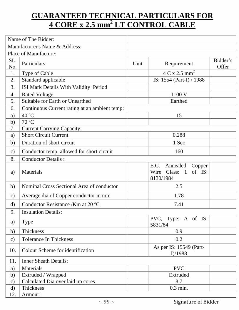
~ 99 ~ Signature of Bidder
GUARANTEED TECHNICAL PARTICULARS FOR
4 CORE x 2.5 mm2 LT CONTROL CABLE
Name of The Bidder:
Manufacturer's Name & Address:
Place of Manufacture:
SL.
No. Particulars Unit Requirement
Bidder‟s
Offer
1. Type of Cable
4 C x 2.5 mm2
2. Standard applicable
IS: 1554 (Part-I) / 1988
3. ISI Mark Details With Validity Period
4. Rated Voltage
1100 V
5. Suitable for Earth or Unearthed
Earthed
6. Continuous Current rating at an ambient temp:
a) 40 ºC
15
b) 70 ºC
7. Current Carrying Capacity:
a) Short Circuit Current
0.288
b) Duration of short circuit
1 Sec
c) Conductor temp. allowed for short circuit
160
8. Conductor Details :
a) Materials
E.C. Annealed Copper
Wire Class: 1 of IS:
8130/1984
b) Nominal Cross Sectional Area of conductor
2.5
c) Average dia of Copper conductor in mm
1.78
d) Conductor Resistance /Km at 20 ºC
7.41
9. Insulation Details:
a) Type
PVC, Type: A of IS:
5831/84
b) Thickness
0.9
c) Tolerance In Thickness
0.2
10. Colour Scheme for identification
As per IS: 15549 (Part-
I)/1988
11. Inner Sheath Details:
a) Materials
PVC
b) Extruded / Wrapped
Extruded
c) Calculated Dia over laid up cores
8.7
d) Thickness
0.3 min.
12. Armour:
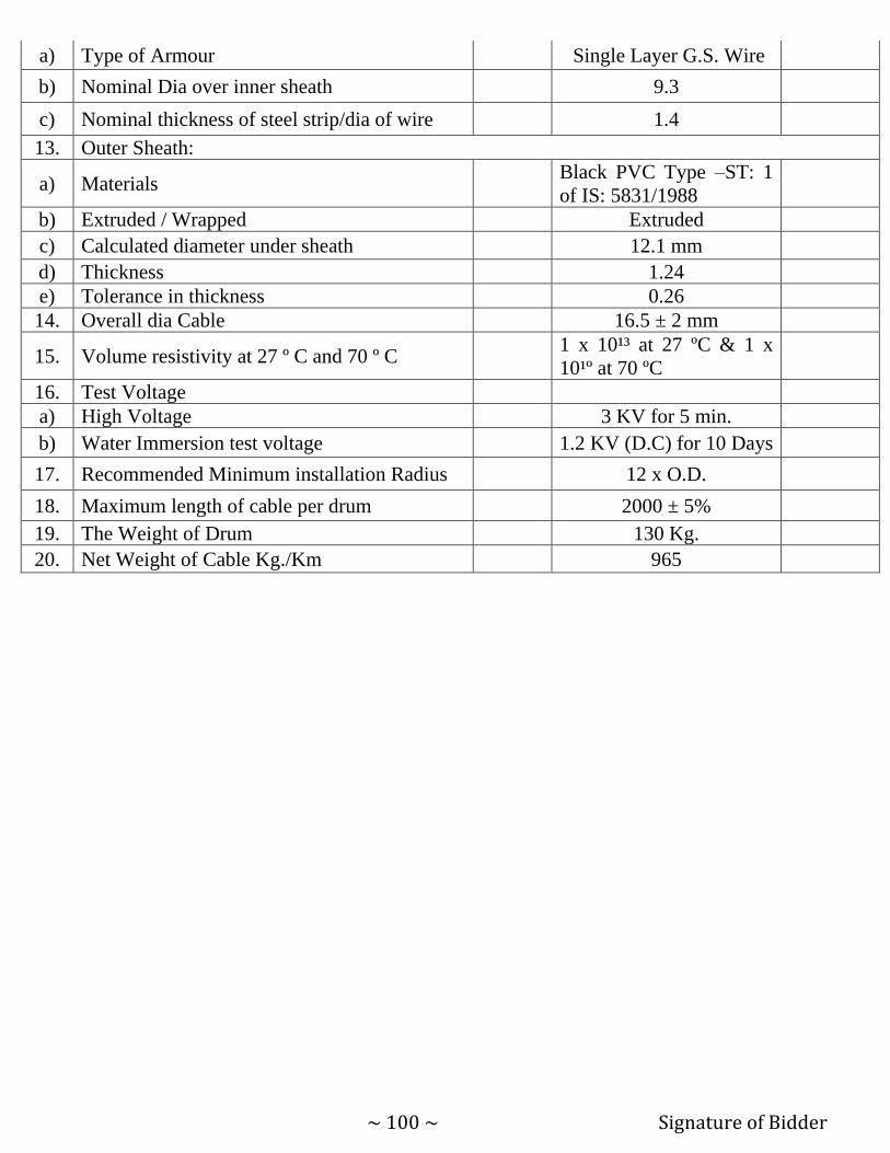
~ 100 ~ Signature of Bidder
a) Type of Armour
Single Layer G.S. Wire
b) Nominal Dia over inner sheath
9.3
c) Nominal thickness of steel strip/dia of wire
1.4
13. Outer Sheath:
a) Materials
Black PVC Type –ST: 1
of IS: 5831/1988
b) Extruded / Wrapped
Extruded
c) Calculated diameter under sheath
12.1 mm
d) Thickness
1.24
e) Tolerance in thickness
0.26
14. Overall dia Cable
16.5 ± 2 mm
15. Volume resistivity at 27 º C and 70 º C
1 x 10¹³ at 27 ºC & 1 x
10¹º at 70 ºC
16. Test Voltage
a) High Voltage
3 KV for 5 min.
b) Water Immersion test voltage
1.2 KV (D.C) for 10 Days
17. Recommended Minimum installation Radius
12 x O.D.
18. Maximum length of cable per drum
2000 ± 5%
19. The Weight of Drum
130 Kg.
20. Net Weight of Cable Kg./Km
965
~ 101 ~ Signature of Bidder
SECTION – IV
ANNEXURES
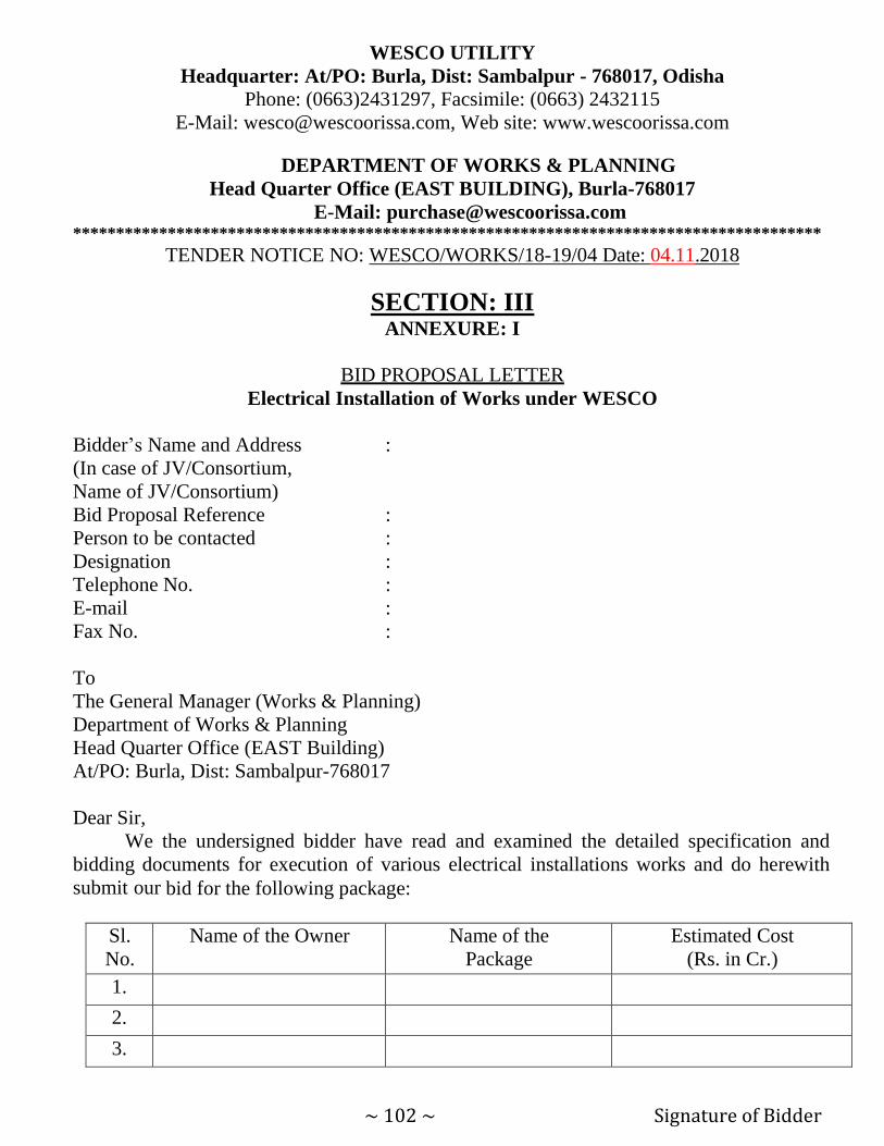
~ 102 ~ Signature of Bidder
WESCO UTILITY
Headquarter: At/PO: Burla, Dist: Sambalpur - 768017, Odisha
Phone: (0663)2431297, Facsimile: (0663) 2432115
E-Mail: [email protected], Web site: www.wescoorissa.com
DEPARTMENT OF WORKS & PLANNING
Head Quarter Office (EAST BUILDING), Burla-768017
E-Mail: [email protected] ***************************************************************************************
TENDER NOTICE NO: WESCO/WORKS/18-19/04 Date: 04.11.2018
SECTION: III ANNEXURE: I
BID PROPOSAL LETTER
Electrical Installation of Works under WESCO
Bidder‟s Name and Address :
(In case of JV/Consortium,
Name of JV/Consortium)
Bid Proposal Reference :
Person to be contacted :
Designation :
Telephone No. :
E-mail :
Fax No. :
To
The General Manager (Works & Planning)
Department of Works & Planning
Head Quarter Office (EAST Building)
At/PO: Burla, Dist: Sambalpur-768017
Dear Sir,
We the undersigned bidder have read and examined the detailed specification and
bidding documents for execution of various electrical installations works and do herewith
submit our bid for the following package:
Sl.
No.
Name of the Owner Name of the
Package
Estimated Cost
(Rs. in Cr.)
1.
2.
3.

~ 103 ~ Signature of Bidder
We declare the following:
1.0 PRICES AND VALIDITY:
1.1 All the prices and price components stated in our bid proposal are firm and not subject
to any price adjustment, in line with the bidding documents. All the prices and other
terms and conditions of this proposal are valid for a period of 180 days from the date of
opening of the bids. We further declare that prices stated in our proposal are in
accordance with “Instructions to Bidders” of bidding documents.
1.2 We do hereby confirm that our bid prices as quoted in attached Schedules include all
import duties and levies including license fees lawfully payable by us on imported items
and other taxes, duties and levies applicable on bought – out components, materials,
equipment and other items and confirm that any such taxes, duties and levies
additionally payable shall be to our account.
1.3 We confirm that the G.S.T. on Works Contract, Turnover Tax or any other similar
taxes, as applicable, are included in our quoted bid price and there shall not be any
liability on this account to the Owner. We understand that Owner shall, deduct such
taxes at source as per the rules and issue TDS Certificate to us.
1.4 We confirm that, in our Bid Price, we have considered G.S.T. in line with lawful
prevalent practice.
1.5 Price components of various items are indicated in the B.O.Q. for the works.
1.6 We further declare that while quoting the price, the due credit under Input tax credit
scheme, as per relevant Government policies wherever applicable, have been taken into
account.
1.7 We, having studied the bidding document in three volumes relating to taxes & duties
and hereby, declare that if any income tax, charge on income tax or any other corporate
tax is attracted under the law, we agree to pay the same.
1.8 We are aware that the Price schedules do not generally give a full description of the
supplies to be made and work to be performed under each item and we shall be deemed
to have read the Technical Specifications and other bidding documents and drawings to
ascertain the full scope of work included in each item while filling in the related and
prices. We agree that the entered rates and prices shall be deemed to include the full
scope as aforesaid, including overheads and profits.
1.9 We understand that in the price schedule, if there is discrepancy between the unit price
and total price, the same shall be corrected as per relevant provisions.
1.10 We declare that prices for items left blank in the schedules will be deemed to have been
included in other items. The TOTAL for each schedule and the TOTAL of Grand
summary shall be deemed to be the total price for executing the facilities and sections
thereof in complete accordance with the contract, whether or not each item has been
priced.
2.0 CONSTRUCTION OF THE CONTRACT:
We declare that we are making the offer on the basis of indivisible supply-cum-
Erection contract on a single source responsibility basis.
3.0 BID SECURITY (EMD):
We are enclosing Bank Draft / Bank Guarantee No.: __________ dtd. ______
~ 104 ~ Signature of Bidder
amounting to Rs. ______ (Rupees ______ only) issued by Bank ______ branch payable
at Burla/ Sambalpur towards Bid Security against our above Bid. The Bid Security
amount has been computed by adding the Estimated Cost of the work.
4.0 EQUIPMENT PERFORMANCE GURANTEE:
We declare that the ratings and performance figures of the equipment to be furnished
and erected by us are guaranteed. The Guaranteed particulars of different equipments
are enclosed along with our bid.
5.0 BID PRICING:
We further declare that the prices stated in our proposal are in accordance with your
„Instruction of Bidders of Conditions of Contract, of the bid documents.
6.0 PRICE ADJUSTMENT:
We declare that all the prices and price components stated in our offer are on FIRM
price basis.
7.0 QUALIFICATION:
We confirm having submitted the Qualification Data in original plus one copy, as
required by you under clause 2.0 „Invitation for Bids‟. Further we have filled in the
information for qualification requirements. In case you require any further
information in this regard, we agree to furnished the same in time.
8.0 DEVIATIONS:
8.1 We declare that the contract shall be executed strictly in accordance with the
specifications and documents except for the variations and deviations all of which
have been detailed out exhaustively in the following schedules, irrespective of whatever
has been stated to the contrary anywhere else in our proposal.
a) Commercial Deviations Schedule
b) Cost of withdrawal of Deviations on Critical clauses
c) Technical Deviation Schedule
8.2 We confirm that specified stipulation of following critical clauses is acceptable to us
and no deviations/exceptions are taken on any account whatsoever in the following
clauses:
a) Payment Terms :
b) Bid Guarantee :
c) Contract Performance Guarantee :
d) Liquidated Damages for delay :
e) Prices and Price Adjustment :
f) Guarantee / Warrantees :

~ 105 ~ Signature of Bidder
Further, we agree that the additional conditions, deviations, if any, found in our bid
proposal documents other than those stated in attached Deviation Schedules, save that
pertaining to any rebates offered, shall not be given effect to.
9.0 ADDITIONAL INFORMATION:
We have included with this proposal additional information listed. We further confirm
that such additional information does not imply any additional deviation beyond those
covered in appropriate schedules and in case of any contradiction between these
additional information and other provisions of Bid, the latter prevail.
10.0 GURANTEE DECLARATION:
We guarantee that the equipment offered shall meet the rating and performance
requirements stipulated in this specification. The Guarantee Declaration which shall
attract levy of liquidated damages for non-performance is indicated in the relevant
schedule.
11.0 BOUGHTOUT AND SUB-CONTRACTED ITEM:
We are furnishing herewith at appropriate Schedule, the detail of all major item of
supply amounting to more than 10% of our Bid Price, which were propose subletting
giving detail of the name of sub-contractor/sub-vendor and quantity for each item.
12.0 WORK SCHEDULE:
If this proposal is accepted by you, we agree to submit engineering data, provide
services and complete the entire work from time to time, in accordance with schedule
indicated in the proposal. We fully understand that the time schedule stipulated in this
proposal is the essence of the contract, if awarded. The completion schedule of the
various major key phases of the work is indicated in the designated schedule.
13.0 CONTRACT PERFORMANCE GUARANTEE:
We further agree that if our Bid is accepted we shall provide an irrevocable Bank
guarantee towards Contract Performance Guarantee, of value equivalent to ten percent
(10%) of the Contract Price initially valid up to the end of ninety (90) days after the end
of the contract warranty period in the form of Bank Guarantee in your favour within 15
(fifteen) days from the date of „Notice of Award of Contract‟ and enter into a formal
agreement with you immediately thereafter.
Dated this ___________ day of_______ 20__
Thanking you,
Yours faithfully,
(Signature of the Authorized Signatory)
Name: ___________________
Designation: ______________
Seal of the company: ________
Date: _____________________

~ 106 ~ Signature of Bidder
Place:
(Written power of Attorney of all signatories of the bid to commit the Bid must be
enclosed with the Bid. In case of joint venture, the written Power of Attorney of all
signatories from respective partners must be enclosed with the Bid. .
N.B.: Applicable case of a Bid from Joint Venture of Firms. Further, the Bid must be signed
by each partner of the Joint venture.
~ 107 ~ Signature of Bidder
ANNEXURE – II
To The General Manager (Works & Planning) Department of Works & Planning Head Quarter Office (EAST Building) At/PO: Burla, Dist: Sambalpur-768017
Sir, Having examined the above specifications together with the Tender terms and conditions
referred to therein:
1) I / We the undersigned do hereby offer to execute the contract covered there on in
complete shape in all respects as per the rules entered in the attached contract schedule
of prices in the tender.
2) I / We do hereby under take to have executed the contract within the time specified in
the tender.
3) 3 – I / We do hereby guarantee the technical particulars given in the tender supported
with necessary reports from concerned authorities.
4) I / We do hereby certify to have purchased a copy of the tender specifications by
remitting Cash / Demand draft & this has been duly acknowledged by you in your letter
No.: __________ dtd. _________.
5) I / We do hereby agree to furnish the composite Bank Guarantee in the manner specified
/ acceptable by WESCO (as the case may be) & for the sum as applicable to me / us as
per clause No.29 of Section-II of this specification within fifteen days of issue of
Letter of Award / Work Order, in the event of Work order being decided in my / us
favour, failing which I / We clearly understand that the said LOA / W.O. shall be liable
to be withdrawn by the Owner.
Signed this ________ Day of __________ 20______
Yours faithfully
(Signature of Bidder with Seal of Company)
~ 108 ~ Signature of Bidder
ANNEXURE – III
PROFORMA FOR COMPOSITE BANK GUARANTEE FOR SECURITY DEPOSIT,
PAYMENT & PERFORMANCE
This Guarantee Bond is executed this ___ day of ___ by us the __________ Bank at _______
P.O. _____ P.S. _______ Dist. ________ State __________
(The Administrator, WESCO Utility, Burla)
Whereas WESCO Utility having head quarter office at Burla, Sambalpur-768017 (here in
after called “the Purchaser”) has placed Purchase Order No._________ Dt.___________
(hereinafter called “the Agreement”) with M/s. _________________ (hereinafter called “the
Contractor”) for supply of ________________ (name of the material) and whereas WESCO
Utility has agreed (1) to exempt the Contractor from making payment of security deposit, (2)
to release 100% payment of the cost of materials as per the said agreement and (3) to exempt
from performance guarantee on furnishing by the Contractor to the Purchaser a composite
Bank Guarantee of the value of 10% (ten percent) of the Contract price of the said
Agreement.
1. Now, therefore, in consideration of Purchaser having agreed (1) to exempt the
Contractor for making payment of security deposit, (2) to release 100% payment to the
Contractor and (3) to exempt from furnishing performance guarantee in terms of the said
Agreement as aforesaid, we the ___________ Bank, Address ___________ (code No.
____) (hereinafter referred to as “the Bank”) do hereby undertake to pay to the
Purchaser an amount not exceeding Rs.________ (Rupees ___________) only against
any loss or damage caused to or suffered by Purchaser by reason of any breach by the
said Contractor(s) of any of the terms or conditions contained in the said Agreement.
2. We, the_____ Bank do hereby undertake to pay the amounts due and payable under the
guarantee without any demur, merely on a demand from Purchaser stating that the
amount claimed is due by way of loss or damage caused to or suffered by Purchaser by
reason of any breach by the said Contractor(s) of any of the terms or conditions
contained in the said Agreement or by the reason of any breach by the said Contractor‟s
failure to perform the said Agreement. Any such demand made on the Bank shall be
conclusive as regards the amount due and payable by the Bank under this Guarantee.
However, our liability under this guarantee shall be restricted to an amount not
exceeding Rs.______ (Rupees ______ ) only.
3. We, the ________________________ Bank also undertake to pay to Purchaser any
money so demanded not withstanding any dispute or dispute raised by the Contractor(s)
in any suit or proceeding instituted/ pending before any court or Tribunal relating
thereto our liability under this Agreement being absolute and irrevocable. The payment
so made by us under this bond shall be valid discharge of our liability for payment there
under and the Contractor(s) shall have no claim against us for making such payment.
~ 109 ~ Signature of Bidder
4. We, the ____________ Bank further agree that the guarantee herein contain shall
remain in full force and affect during the period that would be taken for the performance
of the said Agreement and it shall continue to remain in force till all the dues of
Purchaser under by virtue of the said Agreement have been fully paid and its claim
satisfied or discharged or till Purchaser certifies that the terms and conditions of the said
Agreement have been fully and properly carried out by the said Contractor(s) and
accordingly discharge this guarantee and will not be revoked by us during the validity of
the guarantee period.
Unless a demand or claim under this guarantee is made on us or with_____________
____________________________________ (Local Bank Name, address and code No.)
_________________________________________________, Burla / Sambalpur in
writing on or before __________________ (date) we shall be discharged from all
liability under this guarantee thereafter.
5. We, the _________________________ Bank further agree that Purchaser shall have the
fullest liberty without our consent and without affecting in any manner our obligations
hereunder to vary any of the terms and conditions of the said Agreement or to extend
time of performance by the said Contractor(s) and we shall not be relieved from our
liability by reason of any such variation or extension being granted to the said
Contractor(s) or for any forbearance act or omission on part of Purchaser or any
indulgence by Purchaser to the said Contractor(s) or by any such matter or thing
whatsoever which under the law relating to sureties would but for this provisions have
effect of so relieving us.
6. The Guarantee will not be discharged due to change in the name, style and constitution
of the Bank and or Contractor(s).
7. We, the _________________________ Bank lastly undertake not to revoke this
Guarantee during its currency except with the previous consent of Purchaser in writing.
Dated ___________ the __________ day of Two thousand _________.
Notwithstanding anything contained herein above.
Our liability under this Bank Guarantee shall not exceed Rs.______________ (Rupees
_______ ________________________________________ ) only.
The Bank Guarantee shall be valid up to _____________________ only.
We or our Bank at Burla / Sambalpur (Name & Address of the Local Bank) are liable to
pay the guaranteed amount depending on the filing of claim and any part thereof under
this Bank Guarantee only and only if you serve upon us or our local Bank at Burla /
Sambalpur a written claim or demand and received by us or by Local Branch at Burla /
Sambalpur on or before Dt.__________ otherwise bank shall be discharged of all
liabilities under this guarantee thereafter.
For _____________________________________
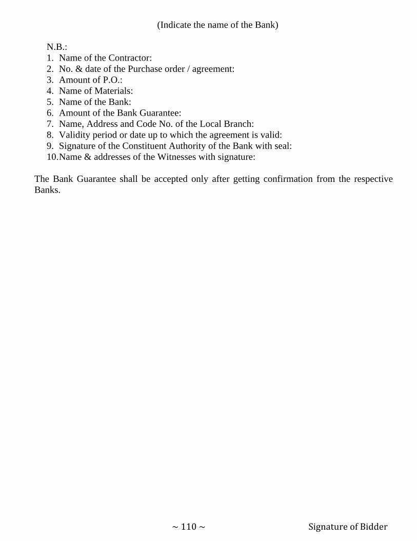
~ 110 ~ Signature of Bidder
(Indicate the name of the Bank)
N.B.:
1. Name of the Contractor:
2. No. & date of the Purchase order / agreement:
3. Amount of P.O.:
4. Name of Materials:
5. Name of the Bank:
6. Amount of the Bank Guarantee:
7. Name, Address and Code No. of the Local Branch:
8. Validity period or date up to which the agreement is valid:
9. Signature of the Constituent Authority of the Bank with seal:
10. Name & addresses of the Witnesses with signature:
The Bank Guarantee shall be accepted only after getting confirmation from the respective
Banks.
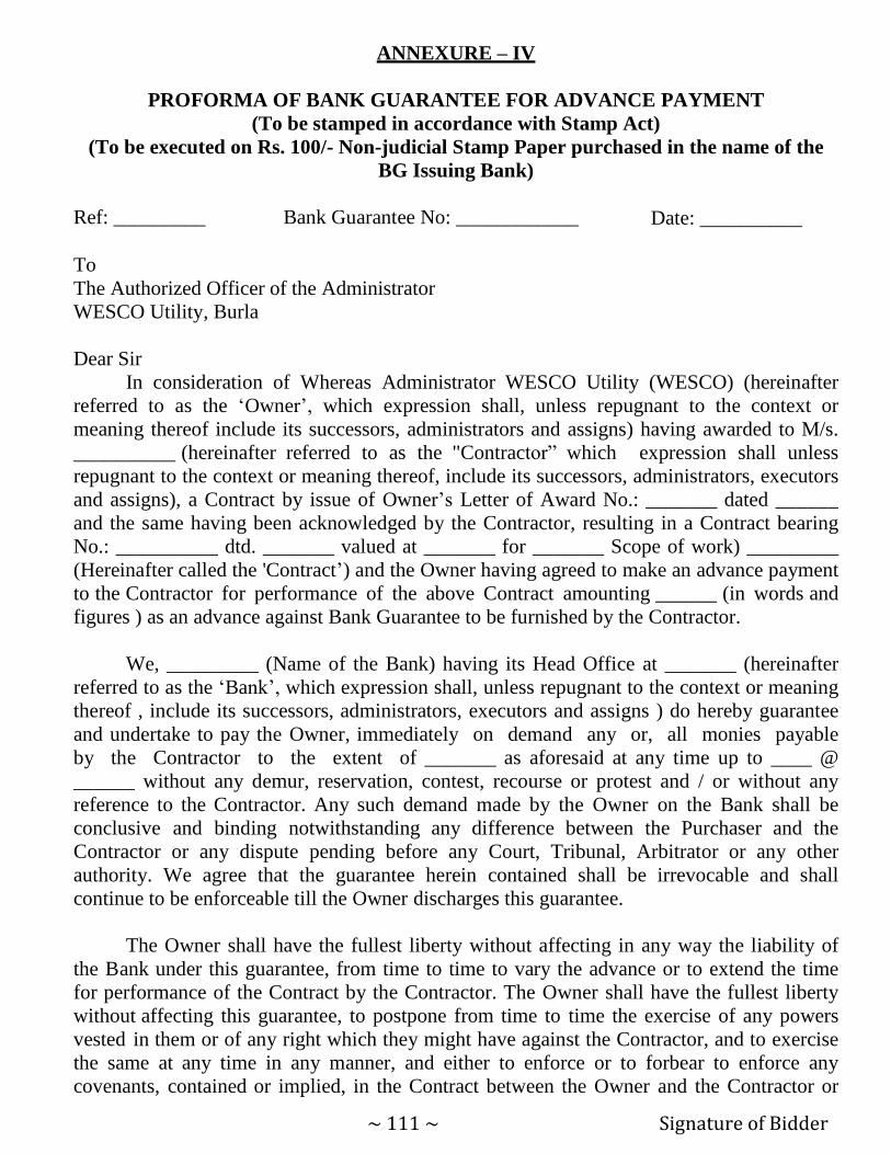
~ 111 ~ Signature of Bidder
ANNEXURE – IV
PROFORMA OF BANK GUARANTEE FOR ADVANCE PAYMENT
(To be stamped in accordance with Stamp Act)
(To be executed on Rs. 100/- Non-judicial Stamp Paper purchased in the name of the
BG Issuing Bank)
Ref: _________ Bank Guarantee No: ____________ Date: __________
To
The Authorized Officer of the Administrator
WESCO Utility, Burla
Dear Sir
In consideration of Whereas Administrator WESCO Utility (WESCO) (hereinafter
referred to as the „Owner‟, which expression shall, unless repugnant to the context or
meaning thereof include its successors, administrators and assigns) having awarded to M/s.
__________ (hereinafter referred to as the "Contractor” which expression shall unless
repugnant to the context or meaning thereof, include its successors, administrators, executors
and assigns), a Contract by issue of Owner‟s Letter of Award No.: _______ dated ______
and the same having been acknowledged by the Contractor, resulting in a Contract bearing
No.: __________ dtd. _______ valued at _______ for _______ Scope of work) _________
(Hereinafter called the 'Contract‟) and the Owner having agreed to make an advance payment
to the Contractor for performance of the above Contract amounting ______ (in words and
figures ) as an advance against Bank Guarantee to be furnished by the Contractor.
We, _________ (Name of the Bank) having its Head Office at _______ (hereinafter
referred to as the „Bank‟, which expression shall, unless repugnant to the context or meaning
thereof , include its successors, administrators, executors and assigns ) do hereby guarantee
and undertake to pay the Owner, immediately on demand any or, all monies payable
by the Contractor to the extent of _______ as aforesaid at any time up to ____ @
______ without any demur, reservation, contest, recourse or protest and / or without any
reference to the Contractor. Any such demand made by the Owner on the Bank shall be
conclusive and binding notwithstanding any difference between the Purchaser and the
Contractor or any dispute pending before any Court, Tribunal, Arbitrator or any other
authority. We agree that the guarantee herein contained shall be irrevocable and shall
continue to be enforceable till the Owner discharges this guarantee.
The Owner shall have the fullest liberty without affecting in any way the liability of
the Bank under this guarantee, from time to time to vary the advance or to extend the time
for performance of the Contract by the Contractor. The Owner shall have the fullest liberty
without affecting this guarantee, to postpone from time to time the exercise of any powers
vested in them or of any right which they might have against the Contractor, and to exercise
the same at any time in any manner, and either to enforce or to forbear to enforce any
covenants, contained or implied, in the Contract between the Owner and the Contractor or
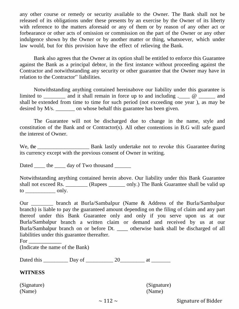
~ 112 ~ Signature of Bidder
any other course or remedy or security available to the Owner. The Bank shall not be
released of its obligations under these presents by an exercise by the Owner of its liberty
with reference to the matters aforesaid or any of them or by reason of any other act or
forbearance or other acts of omission or commission on the part of the Owner or any other
indulgence shown by the Owner or by another matter or thing, whatsoever, which under
law would, but for this provision have the effect of relieving the Bank.
Bank also agrees that the Owner at its option shall be entitled to enforce this Guarantee
against the Bank as a principal debtor, in the first instance without proceeding against the
Contractor and notwithstanding any security or other guarantee that the Owner may have in
relation to the Contractor'‟ liabilities.
Notwithstanding anything contained hereinabove our liability under this guarantee is
limited to ________ and it shall remain in force up to and including .____ @ ______ and
shall be extended from time to time for such period (not exceeding one year ), as may be
desired by M/s. _______ on whose behalf this guarantee has been given.
The Guarantee will not be discharged due to change in the name, style and
constitution of the Bank and or Contractor(s). All other contentions in B.G will safe guard
the interest of Owner.
We, the ___________________ Bank lastly undertake not to revoke this Guarantee during
its currency except with the previous consent of Owner in writing.
Dated ____ the ____ day of Two thousand ______
Notwithstanding anything contained herein above. Our liability under this Bank Guarantee
shall not exceed Rs. ________ (Rupees ______ only.) The Bank Guarantee shall be valid up
to ___________ only.
Our ________ branch at Burla/Sambalpur (Name & Address of the Burla/Sambalpur
branch) is liable to pay the guaranteed amount depending on the filing of claim and any part
thereof under this Bank Guarantee only and only if you serve upon us at our
Burla/Sambalpur branch a written claim or demand and received by us at our
Burla/Sambalpur branch on or before Dt. ____ otherwise bank shall be discharged of all
liabilities under this guarantee thereafter.
For ____________
(Indicate the name of the Bank)
Dated this _________ Day of __________ 20_________ at _______
WITNESS
(Signature) (Signature)
(Name) (Name)

~ 113 ~ Signature of Bidder
(Official Address) (Designation with Bank Stamp)
Attorney as per
Power of Attorney No.:
Date:
@ This date shall be ninety (90) days after the schedule date of completion of
the Contract.
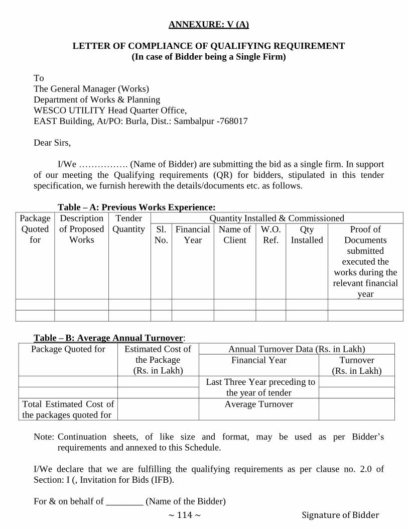
~ 114 ~ Signature of Bidder
ANNEXURE: V (A)
LETTER OF COMPLIANCE OF QUALIFYING REQUIREMENT
(In case of Bidder being a Single Firm)
To
The General Manager (Works)
Department of Works & Planning
WESCO UTILITY Head Quarter Office,
EAST Building, At/PO: Burla, Dist.: Sambalpur -768017
Dear Sirs,
I/We ……………. (Name of Bidder) are submitting the bid as a single firm. In support
of our meeting the Qualifying requirements (QR) for bidders, stipulated in this tender
specification, we furnish herewith the details/documents etc. as follows.
Table – A: Previous Works Experience:
Package
Quoted
for
Description
of Proposed
Works
Tender
Quantity
Quantity Installed & Commissioned
Sl.
No.
Financial
Year
Name of
Client
W.O.
Ref.
Qty
Installed
Proof of
Documents
submitted
executed the
works during the
relevant financial
year
Table – B: Average Annual Turnover:
Package Quoted for Estimated Cost of
the Package
(Rs. in Lakh)
Annual Turnover Data (Rs. in Lakh)
Financial Year Turnover
(Rs. in Lakh)
Last Three Year preceding to
the year of tender
Total Estimated Cost of
the packages quoted for
Average Turnover
Note: Continuation sheets, of like size and format, may be used as per Bidder‟s
requirements and annexed to this Schedule.
I/We declare that we are fulfilling the qualifying requirements as per clause no. 2.0 of
Section: I (, Invitation for Bids (IFB).
For & on behalf of ________ (Name of the Bidder)

~ 115 ~ Signature of Bidder
ANNEXURE: V (B)
LETTER OF COMPLIANCE OF QUALIFYING REQUIREMENT
(In case of Bidder being a Joint Venture / Consortium Firm)
To
The General Manager (Works)
Department of Works & Planning
WESCO UTILITY Head Quarter Office,
EAST Building, At/PO: Burla, Dist.: Sambalpur -768017
Dear Sirs,
I/We ……………. (Name of Bidder) are submitting the bid as a single firm. In support
of our meeting the Qualifying requirements (QR) for bidders, stipulated in this tender
specification, we furnish herewith the details/documents etc. as follows.
Name of the members of the JV / Consortium:
1. ___________________
2. ___________________
Table – A: Previous Works Experience: Name of the Member (any one member only):
Package
Quoted
for
Description
of Proposed
Works
Tender
Quantity
Quantity Installed & Commissioned
Sl.
No.
Financial
Year
Name of
Client
W.O.
Ref.
Qty
Installed
Proof of
Documents
submitted executed
the works during
the relevant
financial year
Table – B: Average Annual Turnover:
Package
Quoted
for
Estimated
Cost of the
Package
(Rs. In Lakh)
Annual Turnover Data (Rs. in
Lakh)
Annual Turnover Data (Rs. in
Lakh)
Financial Year Turn Over (Rs.
In Lakh)
Financial Year Turn Over (Rs.
In Lakh)
Last Three
Year preceding
to the year of
tender
Last Three Year
preceding to
the year of tender
Total
Estimated
Cost of
the
packages
quoted for
Average
Turnover
Average
Turnover

~ 116 ~ Signature of Bidder
Note:
1) Continuation sheets, of like size and format, may be used as per Bidder‟s requirements
and annexed to this Schedule.
2) In case of Joint Venture, separate sheet for each partner of Joint Venture should be
used.
Date: Signature:
Place: Printed Name:
Designation:
Common Seal:
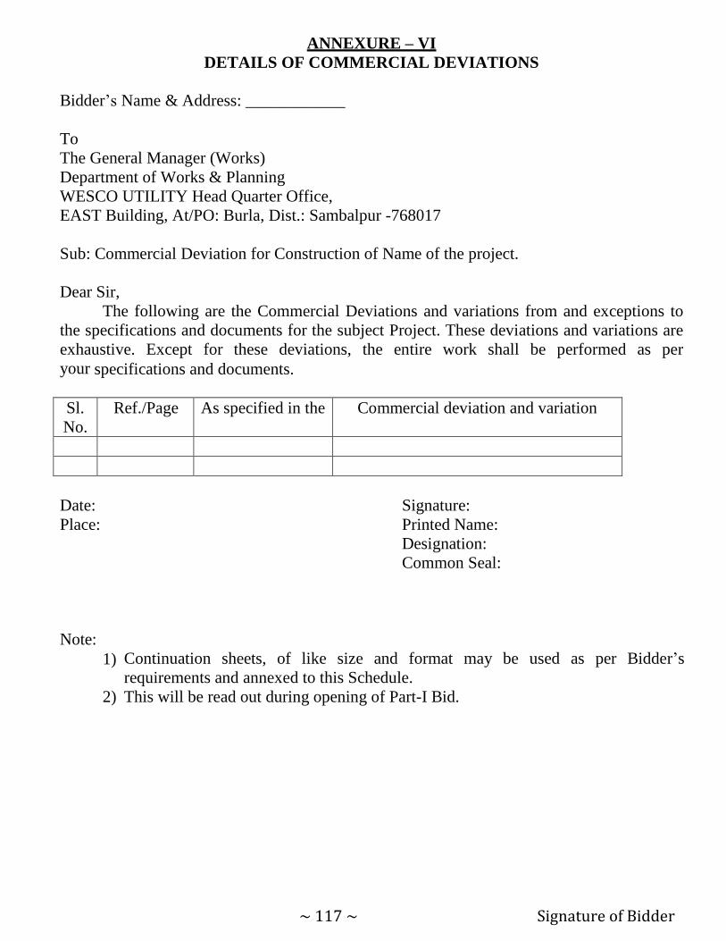
~ 117 ~ Signature of Bidder
ANNEXURE – VI
DETAILS OF COMMERCIAL DEVIATIONS
Bidder‟s Name & Address: ____________
To
The General Manager (Works)
Department of Works & Planning
WESCO UTILITY Head Quarter Office,
EAST Building, At/PO: Burla, Dist.: Sambalpur -768017
Sub: Commercial Deviation for Construction of Name of the project.
Dear Sir,
The following are the Commercial Deviations and variations from and exceptions to
the specifications and documents for the subject Project. These deviations and variations are
exhaustive. Except for these deviations, the entire work shall be performed as per
your specifications and documents.
Sl.
No.
Ref./Page As specified in the Commercial deviation and variation
Date: Signature:
Place: Printed Name:
Designation:
Common Seal:
Note:
1) Continuation sheets, of like size and format may be used as per Bidder‟s
requirements and annexed to this Schedule.
2) This will be read out during opening of Part-I Bid.
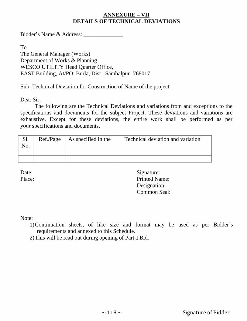
~ 118 ~ Signature of Bidder
ANNEXURE – VII
DETAILS OF TECHNICAL DEVIATIONS
Bidder‟s Name & Address: ______________
To
The General Manager (Works)
Department of Works & Planning
WESCO UTILITY Head Quarter Office,
EAST Building, At/PO: Burla, Dist.: Sambalpur -768017
Sub: Technical Deviation for Construction of Name of the project.
Dear Sir,
The following are the Technical Deviations and variations from and exceptions to the
specifications and documents for the subject Project. These deviations and variations are
exhaustive. Except for these deviations, the entire work shall be performed as per
your specifications and documents.
Sl.
No.
Ref./Page As specified in the Technical deviation and variation
Date: Signature:
Place: Printed Name:
Designation:
Common Seal:
Note:
1) Continuation sheets, of like size and format may be used as per Bidder‟s
requirements and annexed to this Schedule.
2) This will be read out during opening of Part-I Bid.
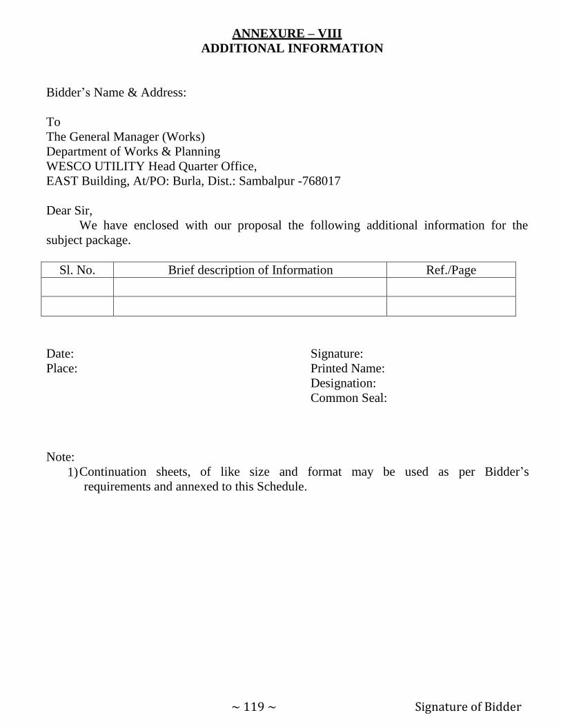
~ 119 ~ Signature of Bidder
ANNEXURE – VIII
ADDITIONAL INFORMATION
Bidder‟s Name & Address:
To
The General Manager (Works)
Department of Works & Planning
WESCO UTILITY Head Quarter Office,
EAST Building, At/PO: Burla, Dist.: Sambalpur -768017
Dear Sir,
We have enclosed with our proposal the following additional information for the
subject package.
Sl. No. Brief description of Information Ref./Page
Date: Signature:
Place: Printed Name:
Designation:
Common Seal:
Note:
1) Continuation sheets, of like size and format may be used as per Bidder‟s
requirements and annexed to this Schedule.
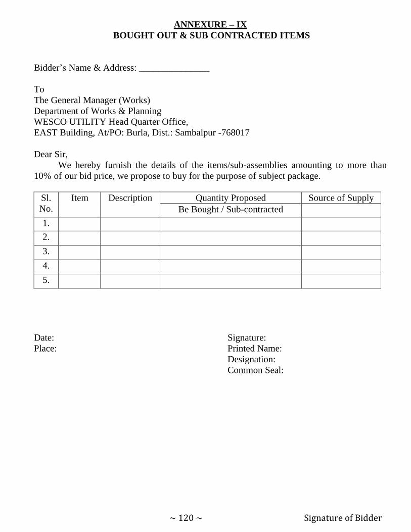
~ 120 ~ Signature of Bidder
ANNEXURE – IX
BOUGHT OUT & SUB CONTRACTED ITEMS
Bidder‟s Name & Address: _______________
To
The General Manager (Works)
Department of Works & Planning
WESCO UTILITY Head Quarter Office,
EAST Building, At/PO: Burla, Dist.: Sambalpur -768017
Dear Sir,
We hereby furnish the details of the items/sub-assemblies amounting to more than
10% of our bid price, we propose to buy for the purpose of subject package.
Sl.
No.
Item Description Quantity Proposed Source of Supply
Be Bought / Sub-contracted
1.
2.
3.
4.
5.
Date: Signature:
Place: Printed Name:
Designation:
Common Seal:
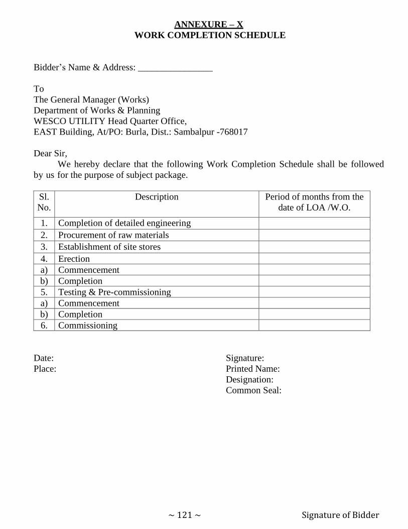
~ 121 ~ Signature of Bidder
ANNEXURE – X
WORK COMPLETION SCHEDULE
Bidder‟s Name & Address: ________________
To
The General Manager (Works)
Department of Works & Planning
WESCO UTILITY Head Quarter Office,
EAST Building, At/PO: Burla, Dist.: Sambalpur -768017
Dear Sir,
We hereby declare that the following Work Completion Schedule shall be followed
by us for the purpose of subject package.
Sl.
No.
Description Period of months from the
date of LOA /W.O.
1. Completion of detailed engineering
2. Procurement of raw materials
3. Establishment of site stores
4. Erection
a) Commencement
b) Completion
5. Testing & Pre-commissioning
a) Commencement
b) Completion
6. Commissioning
Date: Signature:
Place: Printed Name:
Designation:
Common Seal:
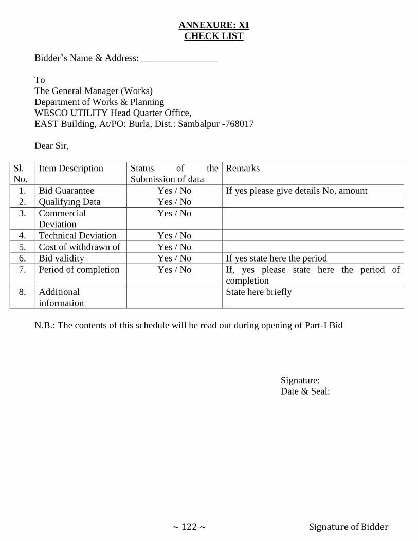
~ 122 ~ Signature of Bidder
ANNEXURE: XI
CHECK LIST
Bidder‟s Name & Address: ________________
To
The General Manager (Works)
Department of Works & Planning
WESCO UTILITY Head Quarter Office,
EAST Building, At/PO: Burla, Dist.: Sambalpur -768017
Dear Sir,
Sl.
No.
Item Description Status of the
Submission of data
Remarks
1. Bid Guarantee Yes / No If yes please give details No, amount
2. Qualifying Data Yes / No
3. Commercial
Deviation
Yes / No
4. Technical Deviation Yes / No
5. Cost of withdrawn of Yes / No
6. Bid validity Yes / No If yes state here the period
7. Period of completion Yes / No If, yes please state here the period of
completion
8. Additional
information
State here briefly
N.B.: The contents of this schedule will be read out during opening of Part-I Bid
Signature:
Date & Seal:

~ 123 ~ Signature of Bidder
ANNEXURE: XII SELF DECLARATION FORM
Name of the Bidder: __________________________
Tender Notice No: ___________________________
Sir,
1) I / we, the undersigned do hereby declare that, I / we have never ever been blacklisted
and / or there were no debarring actions against us for any default in supply of material
/ equipments or in the performance of the contract entrusted to us in any of the
Electricity Utilities of India.
2) In the event of any such information pertaining to the aforesaid matter found at any
given point of time either during the course of the contract or at the bidding stage,
my bid/contract shall be liable for truncation / cancellation / termination without any
notice at the sole discretion of the owner, without prejudice to the right of WESCO for
claiming compensation/ loss caused due to such hiding of facts.
Yours faithfully,
Signature of the bidder
With seal
Place:
Date:
N.B.: This form shall be duly filled-up and signed by the bidder & submitted along with the
original copy of the Bid.
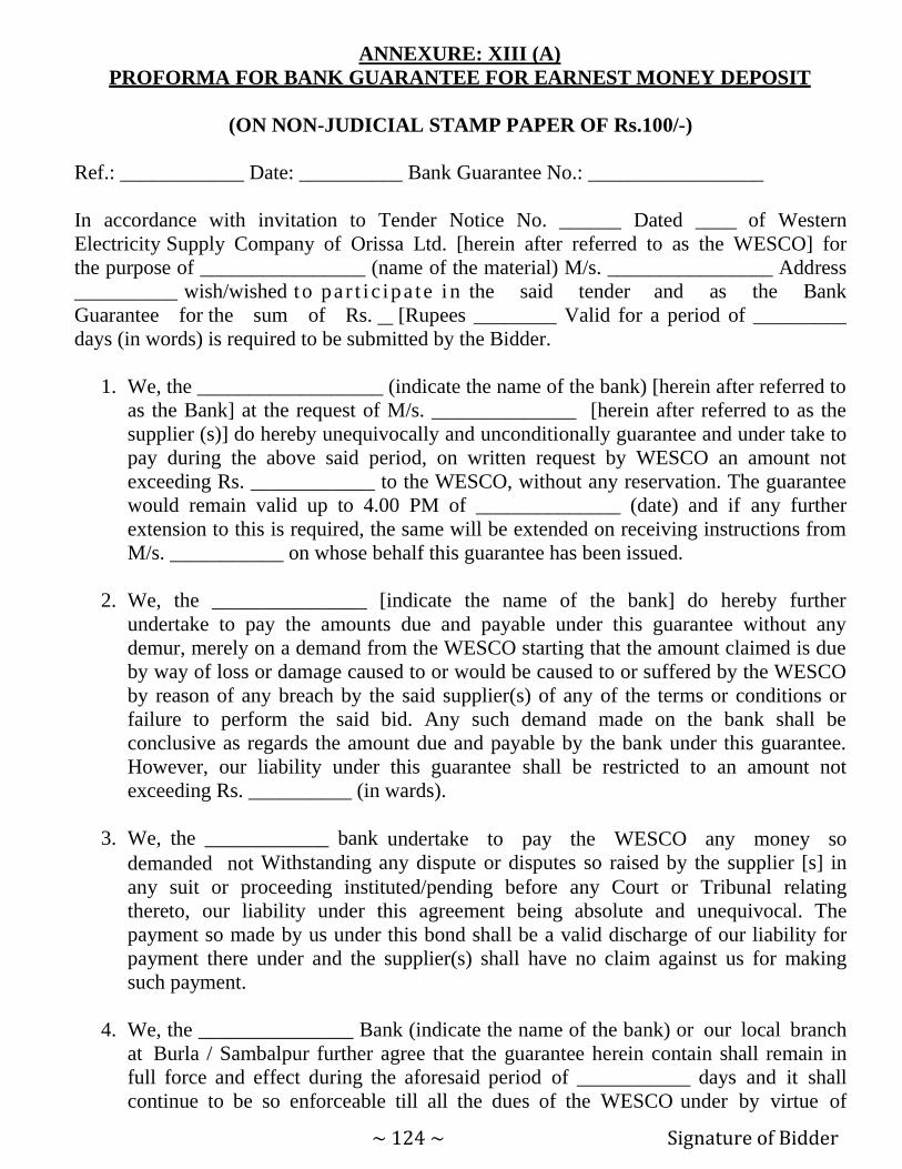
~ 124 ~ Signature of Bidder
ANNEXURE: XIII (A)
PROFORMA FOR BANK GUARANTEE FOR EARNEST MONEY DEPOSIT
(ON NON-JUDICIAL STAMP PAPER OF Rs.100/-)
Ref.: ____________ Date: __________ Bank Guarantee No.: _________________
In accordance with invitation to Tender Notice No. ______ Dated ____ of Western
Electricity Supply Company of Orissa Ltd. [herein after referred to as the WESCO] for
the purpose of ________________ (name of the material) M/s. ________________ Address
__________ wish/wished to pa r t i c ipa te i n the said tender and as the Bank
Guarantee for the sum of Rs. [Rupees ________ Valid for a period of _________ days (in words) is required to be submitted by the Bidder.
1. We, the __________________ (indicate the name of the bank) [herein after referred to
as the Bank] at the request of M/s. ______________ [herein after referred to as the
supplier (s)] do hereby unequivocally and unconditionally guarantee and under take to
pay during the above said period, on written request by WESCO an amount not
exceeding Rs. ____________ to the WESCO, without any reservation. The guarantee
would remain valid up to 4.00 PM of ______________ (date) and if any further
extension to this is required, the same will be extended on receiving instructions from
M/s. ___________ on whose behalf this guarantee has been issued.
2. We, the _______________ [indicate the name of the bank] do hereby further
undertake to pay the amounts due and payable under this guarantee without any
demur, merely on a demand from the WESCO starting that the amount claimed is due
by way of loss or damage caused to or would be caused to or suffered by the WESCO
by reason of any breach by the said supplier(s) of any of the terms or conditions or
failure to perform the said bid. Any such demand made on the bank shall be
conclusive as regards the amount due and payable by the bank under this guarantee.
However, our liability under this guarantee shall be restricted to an amount not
exceeding Rs. __________ (in wards).
3. We, the ____________ bank undertake to pay the WESCO any money so
demanded not Withstanding any dispute or disputes so raised by the supplier [s] in
any suit or proceeding instituted/pending before any Court or Tribunal relating
thereto, our liability under this agreement being absolute and unequivocal. The
payment so made by us under this bond shall be a valid discharge of our liability for
payment there under and the supplier(s) shall have no claim against us for making
such payment.
4. We, the _______________ Bank (indicate the name of the bank) or our local branch
at Burla / Sambalpur further agree that the guarantee herein contain shall remain in
full force and effect during the aforesaid period of ___________ days and it shall
continue to be so enforceable till all the dues of the WESCO under by virtue of

~ 125 ~ Signature of Bidder
the said Bid have been fully paid and its claims satisfied or discharged or till
WESCO certifies that the terms and conditions of the said Bid have been fully and
properly carried out by the said Supplier [s] and accordingly discharges this guarantee.
Unless a demand or claim under this guarantee is made on us in writing on or before
__________ (date) we shall be discharged from all liability under this guarantee
thereafter.
5. We, the _______________ Bank (indicate the name of the bank) or our local branch
at Burla / Sambalpur further agree that the WESCO shall have the fullest liberty
without our consent and without affecting in any manner our obligations here under to
vary any of the terms and conditions of the said Bid or to extend time of performance
by the said Supplier [s] from time to time or to postpone for any time or from time
to time any of the powers exercisable by the WESCO against the said supplier [s] and
to forbear or enforce any of the terms and conditions relating to the said bid and we
shall not be relieved from our liability by reason of any such variation, postponement
or extension being granted to the said Supplier [s] or for any forbearance act or
omission on the part of the WESCO or any indulgence by the WESCO to the said
Supplier[s] or by any such matter or thing whatsoever which under the law relating to
sureties would but for this provision, have effect of so relieving us.
6. This guarantee will not be discharged due to the change in the name, style and
constitution of the Bank or the supplier [s].
7. We, the _______________ Bank (indicate the name of the bank) or our local branch
at Burla / Sambalpur lastly undertake not revoke this Guarantee during its currency
except with the previous consent of the WESCO in writing.
8. We, the _______________ Bank further agree that this guarantee shall also be
irrevocable at our place of business at Burla / Sambalpur (Indicate detail address of
local branch with code no.) in the State of Odisha.
Dated __________ day of 2012.
Witness (Signature, names & address)
For _______________ [Indicate the name of the bank]
1. Power of Attorney No.: ___________
2. Date: _________
SEAL OF BANK
The non-judicial stamp paper of worth Rs. 100/- shall be purchased in the name of the
bank, which has issued the bank guarantee.
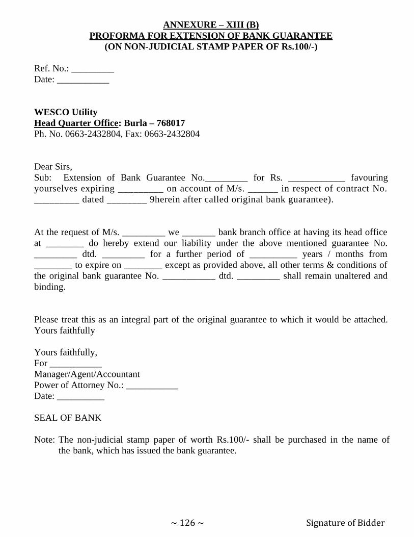
~ 126 ~ Signature of Bidder
ANNEXURE – XIII (B)
PROFORMA FOR EXTENSION OF BANK GUARANTEE
(ON NON-JUDICIAL STAMP PAPER OF Rs.100/-)
Ref. No.: _________
Date: ___________
WESCO Utility
Head Quarter Office: Burla – 768017
Ph. No. 0663-2432804, Fax: 0663-2432804
Dear Sirs,
Sub: Extension of Bank Guarantee No._________ for Rs. ____________ favouring
yourselves expiring _________ on account of M/s. ______ in respect of contract No.
_________ dated ________ 9herein after called original bank guarantee).
At the request of M/s. _________ we _______ bank branch office at having its head office
at ________ do hereby extend our liability under the above mentioned guarantee No.
_________ dtd. _________ for a further period of __________ years / months from
________ to expire on ________ except as provided above, all other terms & conditions of
the original bank guarantee No. ___________ dtd. _________ shall remain unaltered and
binding.
Please treat this as an integral part of the original guarantee to which it would be attached.
Yours faithfully
Yours faithfully,
For ___________
Manager/Agent/Accountant
Power of Attorney No.: ___________
Date: __________
SEAL OF BANK
Note: The non-judicial stamp paper of worth Rs.100/- shall be purchased in the name of
the bank, which has issued the bank guarantee.
~ 127 ~ Signature of Bidder
ANNEXURE: XIV
PROFORMA OF INDEMNITY BOND TO BE EXECUTED BY THE
CONTRACTOR FOR THE EQUIPMENT/MATERIAL HANDED OVER BY
WESCO FOR PERFORMANCE OF ITS CONTRACT
(Entire Equipment consignment in one lot)
(On non-Judicial stamp paper of appropriate Value)
(INDEMNITY BOND)
THIS INDEMNITY BOND is made this _____ day of ____ 20____ by _______ a
Company registered under the Companies Act, 1956/ Partnership Firm / Proprietary
Concern having its Registered Office at ______ (hereinafter called as “Contractor” or
“Obligor” which expression shall include its successors and permitted assigns) in favour of
WESCO Utility, Headquarter At/Po-Burla, Dist-Sambalpur (here in after called
“Owner”)”Which expression shall include its successors and assigns):
WHEREAS Owner has awarded to the Contractor a Contract for _____ vide its Letter of
Award / Contract No.: ______ dtd. ______ and its Amendment No.: _______ and
Amendment No.: _____ (applicable when amendments have been issued) hereinafter called
the “Contract”) in terms of which Owner is required to handover various equipment to the
Contractor for execution of the Contract.
And WHERAS by virtue of Clause No.: _____ of the said Contract, the Contractor is
required to executive an Indemnity Bond in favour of Owner for the Equipment/Material
handed over to it by Owner for the purpose of performance of the Contract / Erection portion
of the Contract (hereinafter called the “Equipment”).
NOW THEREFORE, This Indemnity Bond witness as follows:
That in consideration of various equipment as mentioned in the Contract, valued at Rs.
_____ / - (Rupees _______ only) handed over to the Contractor for the purpose of
performance of the Contract, the Contractor hereby undertakes to indemnify and shall
keep Owner indemnified, for the full value of the Equipment. The Contractor hereby
acknowledges receipt of the Equipment as per dispatch title documents handed over to the
Contractor duly endorsed in their favour and detailed in the Schedule appended hereto. It is
expressly understood by the Contractor that handing over of the dispatch title documents in
respect of the said Equipment duly endorsed by Owner in favour of the Contractor shall be
construed as handing over of the Equipment purported to be covered by such title documents
and the Contractor shall hold such Equipment is trust as a Trustee for and on behalf of
Owner.
That the Contractor is obliged and shall remain absolutely responsible for the safe transit /
protection and custody of the Equipment at Owner project Site against all risks,
whatsoever, till the Equipment are duly used / erected in accordance with the terms of the
Contract and the Plant / Package duly erected and commissioned in accordance with the
terms of the Contract, is taken over by Owner. The Contractor undertakes to keep Owner
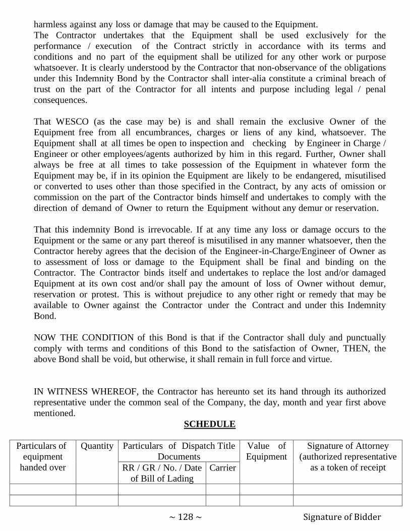
~ 128 ~ Signature of Bidder
harmless against any loss or damage that may be caused to the Equipment.
The Contractor undertakes that the Equipment shall be used exclusively for the
performance / execution of the Contract strictly in accordance with its terms and
conditions and no part of the equipment shall be utilized for any other work or purpose
whatsoever. It is clearly understood by the Contractor that non-observance of the obligations
under this Indemnity Bond by the Contractor shall inter-alia constitute a criminal breach of
trust on the part of the Contractor for all intents and purpose including legal / penal
consequences.
That WESCO (as the case may be) is and shall remain the exclusive Owner of the
Equipment free from all encumbrances, charges or liens of any kind, whatsoever. The
Equipment shall at all times be open to inspection and checking by Engineer in Charge /
Engineer or other employees/agents authorized by him in this regard. Further, Owner shall
always be free at all times to take possession of the Equipment in whatever form the
Equipment may be, if in its opinion the Equipment are likely to be endangered, misutilised
or converted to uses other than those specified in the Contract, by any acts of omission or
commission on the part of the Contractor binds himself and undertakes to comply with the
direction of demand of Owner to return the Equipment without any demur or reservation.
That this indemnity Bond is irrevocable. If at any time any loss or damage occurs to the
Equipment or the same or any part thereof is misutilised in any manner whatsoever, then the
Contractor hereby agrees that the decision of the Engineer-in-Charge/Engineer of Owner as
to assessment of loss or damage to the Equipment shall be final and binding on the
Contractor. The Contractor binds itself and undertakes to replace the lost and/or damaged
Equipment at its own cost and/or shall pay the amount of loss of Owner without demur,
reservation or protest. This is without prejudice to any other right or remedy that may be
available to Owner against the Contractor under the Contract and under this Indemnity
Bond.
NOW THE CONDITION of this Bond is that if the Contractor shall duly and punctually
comply with terms and conditions of this Bond to the satisfaction of Owner, THEN, the
above Bond shall be void, but otherwise, it shall remain in full force and virtue.
IN WITNESS WHEREOF, the Contractor has hereunto set its hand through its authorized
representative under the common seal of the Company, the day, month and year first above
mentioned.
SCHEDULE
Particulars of
equipment
handed over
Quantity Particulars of Dispatch Title
Documents
Value of
Equipment
Signature of Attorney
(authorized representative
as a token of receipt RR / GR / No. / Date
of Bill of Lading
Carrier
~ 129 ~ Signature of Bidder
For an on behalf of M/s. _______________________
WITNESS
Signature: ______________ Signature: _________ Signature: ___________
Name: __________ Name: ______________ Name: _____________
Address: __________ Address: __________ Address:_____________
Authorized representative
(Common Seal in case of Company)
Indemnity Bonds are to be executed by the authorized person and (i) in case of
Contracting Company under common seal of the Company or (ii) having the Power of
Attorney issued under common seal of the company with authority to execute Indemnity
Bonds, (iii) In case of (ii), the original Power of Attorney if it is specifically for this
Contract or a Photostat copy of the Power of Attorney if it is General Power of Attorney
and such documents should be attached to Indemnity Bond.