Embed Size (px)
Citation preview

Cisco Small Business
RV220W Wireless-N Network Security Firewall
ADMINISTRATION GUIDE

© 2011 Cisco Systems, Inc. All rights reserved. 78-19743-01 D0
Cisco and the Cisco logo are trademarks or registered trademarks of Cisco and/or its affiliates in the U.S. and other countries. To view a list of Cisco trademarks,
go to this URL: www.cisco.com/go/trademarks. Third-party trademarks mentioned are the property of their respective owners. The use of the word partner
does not imply a partnership relationship between Cisco and any other company. (1110R)

Contents
Chapter 1: Introduction 11
Product Overview 11
Configuring the RV220W 12
Logging In 12
Setting Up the Cisco RV220W Using the Setup Wizard 13
Using the Getting Started Page 13
Features of the User Interface 14
Suggested Next Steps 15
Chapter 2: Configuring Networking 16
WAN Settings for IPv4 16
Configuring the IPv4 WAN Settings 17
PPPoE Profiles for Point-to-Point Protocol over Ethernet Connections 20
Managing PPPoE Profiles 20
Adding and Editing PPPoE Profile Settings 21
LAN Configuration for IPv4 22
IPv4 LAN (Local Network) 22
VLAN Membership 24
Multiple VLAN Subnets 26
Viewing the Multiple VLAN Subnets Table 26
Entering the Multiple VLAN Subnets Properties 26
Static DHCP 28
Advanced DHCP Configuration 29
DHCP Leased Clients 30
Jumbo Frames 30
Routing 31
Routing Mode 31
Routing Table 32
Static Routes 33
Managing Static Routes 33
Configuring Static Routes 34
Dynamic Routing 35
Port Management 37
Cisco RV220W Administration Guide 3

Contents
Dynamic DNS 38
IPv6 39
IP Mode 39
IPv6 WAN (Internet) 40
Configuring IPv6 LAN Properties 41
Configuring IPv6 Static Routing 43
Managing IPv6 Static Routes 43
Configuring an IPv6 Static Route 44
Configuring IPv6-to-IPv4 Tunneling 45
Configuring an ISATAP Tunnel 46
Configuring Router Advertisement 46
RADVD Advertisement Prefixes 48
Managing Advertisement Prefixes 48
Adding and Editing Advertisement Prefixes 49
Chapter 3: Configuring the Wireless Network 50
About Wireless Security 50
Wireless Security Tips 51
General Network Security Guidelines 52
Basic Settings 53
Security Settings for Wireless Networks 56
MAC Filtering for Wireless Network Access Control 58
Connected Clients 59
Wi-Fi Multimedia and Quality of Service Settings 60
SSID Schedule for Network Availability 61
Advanced Settings 62
Wireless Distribution System (WDS) 63
Chapter 4: Firewall 64
Cisco RV220W Firewall Features 64
Access Rules 66
Setting the Default Outbound Policy and Managing Access Rules 66
Adding and Editing Access Rules 67
Cisco RV220W Administration Guide 4
Contents
Changing Access Rule Priorities 71
Attack Prevention 72
Content Filtering 73
URL Blocking 75
Port Triggering 76
Managing Port Triggering Rules 77
Adding and Editing Port Triggering Rules 77
Port Forwarding 78
Managing Port Forwarding Rules 78
Adding or Editing a Port Forwarding Rule 79
DMZ Host 82
Advanced Firewall Settings 82
One-to-One Network Address Translation (NAT) 83
Managing One-to-One NAT Rules 83
Adding or Editing a One-to-One NAT Rule 84
MAC Address Filtering 85
IP/MAC Address Binding 86
Custom Services 87
Managing Custom Services 87
Adding or Editing a Custom Service 88
Schedules for Firewall Rules and Port Forwarding Rules 89
Managing Schedules 89
Adding or Editing a Schedule 90
Session Settings 91
Internet Group Management Protocol (IGMP) 92
Enabling IGMP and Managing the Allowed Networks Table 92
Adding or Editing the Allowed Networks 93
SIP ALG 93
Firewall Configuration Examples 94
Chapter 5: Cisco ProtectLink Web 98
Getting Started with Cisco ProtectLink Web 98
Global Settings for Approved URLs and Clients 99
Cisco RV220W Administration Guide 5

Contents
Approved Clients 99
Approved URLs 100
Web Protection 101
Overflow Control 101
Web Reputation 102
URL Filtering 103
Updating the ProtectLink License 104
Summary 104
Renewal 105
Chapter 6: Configuring Virtual Private Networks (VPNs) and Security 106
Configuring VPNs 107
Basic VPN Setup 109
Configuring Advanced VPN Parameters 111
Managing IKE and VPN Policies 112
Configuring IKE Policies 113
Configuring VPN Policies 117
Configuring VPN Users 122
Configuring VPN Passthrough 124
SSL VPN Server 124
Access Options for SSL VPN 125
Security Tips for SSL VPN 125
Elements of SSL VPN 126
Portal Layouts 126
Managing Portal Layouts 127
Adding or Editing a Portal Layout 127
SSL VPN Policies 129
About SSL VPN Policies 129
Managing SSL VPN Policies 129
Configuring an SSL VPN Policy 130
Resources for SSL VPN 132
Managing Resources 132
Configuring a Resource 132
Cisco RV220W Administration Guide 6

Contents
SSL VPN Port Forwarding 133
Managing Applications and Host Names for Port Forwarding 133
Configuring a TCP Application for SSL VPN Port Forwarding 134
Configuring Host Name Resolution for Port Forwarding 135
SSL VPN Tunnel Client Configuration 136
SSL VPN Client 136
Configured Client Routes for Split Tunnel Mode 138
Managing Client Routes 138
Configuring a Client Route 139
Viewing the SSL VPN Client Portal 139
Chapter 7: Configuring Security 141
Using SSL Certificates for Authentication 141
Importing a Trusted Certificate from a File 143
Importing an Active Self Certificate from a File 143
Generating a Certificate Request 144
Viewing a Certificate Request 145
Using the Cisco RV220W With a RADIUS Server 146
Managing RADIUS Server Configurations 146
Adding or Editing a RADIUS Server Configuration 147
Configuring 802.1x Port-Based Authentication 148
Chapter 8: Configuring Quality of Service 149
WAN QoS Profiles 149
Profile Binding 151
Managing Profile Binding Rules 151
Configuring a Profile Binding Rule 152
CoS Settings 153
CoS Settings for Traffic Forwarding Queues 153
CoS to DSCP Remarking 154
Chapter 9: Administering Your Cisco RV220W 155
Password Rules for Password Complexity 156
Cisco RV220W Administration Guide 7

Contents
Remote Management 157
User Management 158
Domains 158
Managing Domains 159
Configuring a Domain 159
Groups 161
Managing Groups for a Domain 161
Configuring a Group 162
Users 163
Managing Users 163
Configuring a User 164
User Log in Policies 165
User Log in Policies by Client Browser 166
User Log in Policies by IP Address 167
Network Management (SNMP) 169
SNMP Users and Trap Settings 169
Managing User Security Settings and Trap Settings 169
Configuring the User Security Settings for SNMP 170
Configuring SNMP Traps 171
SNMP System Information 171
WAN Traffic Meter 172
Diagnostics 174
Network Tools 174
Capture Packets 176
Logging 176
Logging Policies 176
Managing Logging Policies 177
Configuring a Logging Policy 177
Firewall Logs 178
Remote Logging Configuration 180
Discovery Settings 182
Discovery Settings for Bonjour 182
UPnP Discovery 183
Time Settings 184
Cisco RV220W Administration Guide 8

Contents
Backing Up or Restoring a Configuration 185
CSV File Import for User Accounts 186
Creating a CSV File 186
Importing a CSV File 189
Firmware Upgrade 189
Rebooting the Cisco RV220W 190
Restoring the Factory Defaults 190
Chapter 10: Viewing the RV220W Status 192
Viewing the Dashboard 193
Viewing the System Summary 196
Viewing the Wireless Statistics 199
Viewing the IPsec Connection Status 200
Viewing the VPN Client Connection Status 201
Viewing Logs 202
Viewing Available LAN Hosts 202
Viewing the Port Triggering Status 203
Viewing Interface Statistics 203
Viewing Port Statistics 204
Viewing Open Ports 206
Viewing Active Users 206
Viewing the SSL VPN Connection Information Status 207
Appendix A: Installing the Cisco RV220W 209
Getting to Know the Cisco RV220W 209
Front Panel 209
Back Panel 210
Mounting the Cisco RV220W 211
Placement Tips 211
Wall Mounting 211
Cisco RV220W Administration Guide 9

Contents
Attaching the Antennas 214
Connecting the Equipment 214
Verifying the Hardware Installation 216
Connecting to Your Wireless Network 217
Appendix B: Using Cisco QuickVPN 218
Overview 218
Before You Begin 218
Installing the Cisco QuickVPN Software 219
Installing from the CD-ROM 219
Downloading and Installing from the Internet 221
Using the Cisco QuickVPN Software 221
Appendix C: Glossary 224
Appendix D: Where to Go From Here 228
Cisco RV220W Administration Guide 10

1
Introduction
This introduction provides information to familiarize you with the product features
and help you get started using the web-based Configuration Utility.
Refer to these topics:
• Product Overview, page 11
• Configuring the RV220W, page 12
• Setting Up the Cisco RV220W Using the Setup Wizard, page 13
Product Overview
Thank you for choosing the Cisco Small Business RV220W Wireless-N Network
Security Firewall. The Cisco RV220W is an advanced Internet-sharing network
solution for your small business needs. It allows multiple computers in your office
to share an Internet connection through both wired and wireless connections.
The RV220W Network Security Firewall delivers high-performance, high security,
wired and wireless connectivity—to the Internet, other offices, and employees
working remotely—to speed file transfers and help improve the productivity of
employees in a small office. Hybrid VPN capabilities, supporting both IP Security
(IPsec) and Secure Sockets Layer (SSL) VPN, provide flexibility to connect remote
offices as if they were physically attached to the network and extend controlled
network access to partners and others. Business-class security and optional
cloud-based web threat protection help keep the network and business assets
safe.
Cisco RV220W Administration Guide 11
Introduction
Configuring the RV220W 1
Configuring the RV220W
After connecting your equipment, use the web-based Configuration Utility to
configure your RV220W.
The Cisco RV220W tries to automatically detect and configure your Internet
settings. However, in some cases you might need to manually configure some
settings using the Device Manager. At a minimum, you should change the default
administrator name and password, and set up wireless security. See these topics
for more information about getting started in the Configuration Utility:
• Setting Up the Cisco RV220W Using the Setup Wizard
• Using the Getting Started Page
• Features of the User Interface
• Suggested Next Steps
NOTE For information about installation, see Appendix A, “Installing the Cisco
RV220W.”
Logging In
STEP 1 Connect a PC to a LAN port of the Cisco RV220W. If DHCP is enabled (the default
setting), your PC becomes a DHCP client of the RV220W and receives an IP
address in the 192.168.1.xxx range.
Note: You may need to configure your PC to obtain its IP address from a DHCP
server.
STEP 2 Start a web browser on your PC.
STEP 3 In the Address bar, enter the LAN IP address of the RV220W. (default 192.168.1.1).
Note: If Bonjour is enabled (the default setting), the RV220W advertise its record
information to any browsing device attached to its network. As a result, you run
Bonjour or FindIT on your PC to automatically discover the RV220W.
The browser may display a message about the site’s security certificate. The
RV220W uses a self security certificate and this message appears because the
RV220W is not known to your PC. You can safely click Continue (or the option
shown on your particular web browser) to go to the web site.
STEP 4 When the login page appears, enter the user name and password. The default
user name is cisco. The default password is cisco. Passwords are case sensitive.
Cisco RV220W Administration Guide 12

Introduction
Configuring the RV220W 1
Note: To prevent unauthorized access, use the Administration > User
Management > Users page to configure more secure login credentials as soon as
possible.
STEP 5 Click Log In.
Setting Up the Cisco RV220W Using the Setup Wizard
With the Cisco RV220W powered on and connected to a PC, use the Setup
Wizard to configure the network settings.
To use the Setup Wizard:
STEP 1 After logging in to the configuration utility, click Run Setup Wizard in the
navigation tree.
STEP 2 Follow the on-screen instructions to set up the Cisco RV220W.
The Setup Wizard tries to automatically detect and configure your connection. If it
cannot, the Setup Wizard asks you for information about your Internet connection.
If you do not have the required information, contact your Internet Service Provider
(ISP) to obtain it.
During the setup process, the Setup Wizard asks you to enter a new password. To
protect your router from unauthorized access, create a new password that is hard
to guess. While you are entering the password, the Setup Wizard provides you
with instant feedback regarding the strength of the password.
After the Setup Wizard is done configuring the Cisco RV220W, the Getting
Started page appears. See Using the Getting Started Page, page 13 for more
information.
Using the Getting Started Page
Use the links on the Getting Started page to perform the most common
configuration tasks. Click a link to perform a task. After performing a task, be sure
to save your new settings. To return to the Getting Started page, click Getting
Started in the navigation tree.
Cisco RV220W Administration Guide 13

Introduction
Configuring the RV220W 1
NOTE When you get a new router, be sure to check Cisco.com for firmware updates. Then
in the Quick Access section of the Getting Started page, use the Update Device
Firmware link to install your new firmware.
The Getting Started page includes these sections:
• Initial Settings—These links are for common tasks that most users need to
perform to configure the Cisco RV220W for the first time. Although the
default settings are sufficient for many small businesses, you should use
these links to review the settings and make changes as needed.
• Quick Access—These links are for common tasks that may be applicable
to your network.
• Device Status—These links provide access to status information for your
network. After configuring your settings, you should use these links to verify
the configuration.
The Other Resources section includes these links:
• Support—Click the link to visit the Cisco RV Series Routers page on
Cisco.com. This page provides links to technical documentation, product
literature, and other resources.
• Forums—Click this link to visit the Cisco Small Business Support
Community on Cisco.com.
To prevent the Getting Started page from showing when the Device Manager is
started, check Don’t show this on start-up.
Features of the User Interface
• Navigating through the pages
Use the navigation tree in the left pane to open the configuration pages.
Click a menu item on the left panel to expand it. Click the menu names
displayed underneath to perform an action or view a sub-menu.
• Saving your changes
Click Save to save your settings, or click Cancel to reload the page with the
current settings. If a page was opened by using an Add or Edit button, you
can click Back to return to the referring page.
Cisco RV220W Administration Guide 14

Introduction
Configuring the RV220W 1
• Viewing the Help files
To view more information about a configuration page, click the Help link
near the top right corner of the page.
Suggested Next Steps
Cisco recommends that you change some default settings to provide better
security and performance. In addition, you may need to manually configure some
settings. A suggested outline of steps follows:
• Change the administrator name and password. See Users, page 163.
• Change the idle timeout value. The Device Manager, by default, logs you out
after 10 minutes of inactivity. For more information, see User Management,
page 158.
• Enable remote management, which is a convenience to you when
configuring the router, and which is required if you want to enable a VPN.
See User Management, page 158.
• If your connection is not working, or your Internet service requires a login
account and password, see WAN Settings for IPv4, page 16.
• If you already have a DHCP server on your network, and you do not want
the Cisco RV220W to act as a DHCP server, see LAN Configuration for
IPv4, page 22.
• Configure your wireless network, especially wireless security. See
Chapter 3, “Configuring the Wireless Network.”
• Configure your Virtual Private Network (VPN).
- You can quickly set up a Gateway-to-Gateway or Client-to-Gateway
VPN by using the VPN > Basic VPN Setup page. For more information,
see Basic VPN Setup, page 109.
- Alternatively, for a simpler VPN setup, you can enable remote
management, configure user accounts, and distribute Cisco QuickVPN
to your remote workers. The Cisco QuickVPN software is found on the
CD that shipped with your router. Also see Using Cisco QuickVPN,
page 218.
Cisco RV220W Administration Guide 15

2
Configuring Networking
The Networking menu provides access to configuration pages where you can
configure your WAN, LAN, and other IPv4 and IPv6 network settings.
Refer to these topics:
• WAN Settings for IPv4, page 16
• LAN Configuration for IPv4, page 22
• Routing, page 31
• Port Management, page 37
• Dynamic DNS, page 38
• IPv6, page 39
WAN Settings for IPv4
Use the Networking > WAN menu to set up your Internet connection for your IPv4
network.
• Configuring the IPv4 WAN Settings, page 17
• PPPoE Profiles for Point-to-Point Protocol over Ethernet Connections,
page 20
NOTE For instructions on configuring your RV220W for an IPv6 network, see the “IPv6”
section on page 39.
Cisco RV220W Administration Guide 16

Configuring Networking
WAN Settings for IPv4 2
Configuring the IPv4 WAN Settings
Follow these instructions to configure your Internet connection for your IPv4
network.
NOTE If your service provider requires PPPoE, first configure a PPPoE profile. See PPPoE
Profiles for Point-to-Point Protocol over Ethernet Connections, page 20.
To open this page: In the navigation tree, choose Networking > WAN (Internet) >
IPv4 WAN (Internet).
STEP 1 In the Internet Connection Type section, choose the type specified by your
service provider. Then enter the required settings for the selected type.
• Automatic Configuration - DHCP—Choose this option if your service
provider gave you a dynamic DHCP connection to the Internet, or your PC
receives its IP address from your cable or DSL modem. This address can
change. No additional settings are required for this connection type.
• Static IP—Choose this option if your service provider gave you an IP
address that does not change. Enter the IP address, mask, default gateway,
and DNS server information. The fields are described in the table below this
step.
• PPPoE—Choose this option if your service provider gave you a Point-to-
Point Protocol over Ethernet (PPPoE) connection to the Internet (used mainly
with asymmetric DSL). In the PPPoE section, choose a PPPoE Profile Name.
If you have not yet created PPPoE profiles, click the Configure Profile
button. For more information, see PPPoE Profiles for Point-to-Point
Protocol over Ethernet Connections, page 20.
• PPTP—Choose this option if your service provider gave you a Point-to-Point
Tunneling Protocol (PPTP) connection to the Internet (used in Europe). In the
PPTP section, enter your user name, password, and connection type, IP
address, and server IP address. Also enable encryption if supported. The
fields are described in the table below this step.
• L2TP—Choose this option if your service provider gave you a Layer 2
Tunneling Protocol (L2TP) connection to the Internet (used in Europe). In the
L2TP section, enter your user name, password, and connection type, IP
address, and server IP address. Optionally, enter the secret phrase. The
fields are described in the table below this step.
Cisco RV220W Administration Guide 17

Configuring Networking
WAN Settings for IPv4 2
IP Address or My
IP Address
Enter the IP address that was assigned to your account.
Subnet Mask Enter the subnet mask specified by your service provider.
Default Gateway Enter the IP address of the default gateway specified by
your service provider.
Primary DNS
Server,
Secondary DNS
Server
For domain name resolution, enter the IP address of the
DNS servers specified by your service provider. The
Primary DNS Server is required for a Static IP connection.
User Name Enter the user name for your Internet account.
Password Enter the password for your Internet account.
Secret If required by your service provider, enter the secret phrase
used to log in to the server.
MPPE Encryption If your service provider’s PPTP server supports Microsoft
Point-to-Point Encryption (MPPE), check the Enable box.
Connection Type Choose the connection type:
• Keep Connected—The Internet connection is
always on.
• Idle Time—The Internet connection is on only when
traffic is present. If the connection is idle—that is, no
traffic is occurring—the connection is closed. You
might want to choose this if your ISP charges based
on the amount of time that you are connected. If you
choose this connection type, enter the number of
minutes after which the connection shuts off in the
Idle Time field.
Server IP
Address
Enter the IP address of the PPTP or L2TP server specified
by your service provider.
Cisco RV220W Administration Guide 18
Configuring Networking
WAN Settings for IPv4 2
STEP 2 In the MTU Size section, choose the MTU Type. (See MTU (Maximum
Transmission Unit) in the glossary.)
• Default—Unless a change is required by your ISP, Cisco recommends that
you use the default setting, 1500 bytes.
• Custom—If your ISP requires a custom MTU setting, choose Custom and
enter the MTU Size specified by your provider.
STEP 3 In the Router MAC Address section, specify the MAC address source. The
RV220W has a unique 48-bit local Ethernet hardware address. In most cases, the
RV220W’s default MAC address is used to identify your Cisco RV220W to your
ISP. However, you can change this setting if required by your ISP.
• Use Default Address (recommended).
• Use this computer's MAC—Choose this option to assign the MAC address
of the computer that you are using to configure the RV220W.
• Use This MAC—Choose this option if you want to manually enter a MAC
Address that is expected by your ISP. Then enter a MAC Address in the
format of XX:XX:XX:XX:XX:XX, where X is a number from 0 through 9 or a
letter from A through F.
STEP 4 Click Save to save your settings, or click Cancel to redisplay the page with the
current settings.
Cisco RV220W Administration Guide 19

Configuring Networking
WAN Settings for IPv4 2
PPPoE Profiles for Point-to-Point Protocol over Ethernet Connections
If you have a Point-to-Point Protocol over Ethernet (PPPoE) connection to the
Internet (used mainly with asymmetric DSL), create a PPPoE profile for your PPPoE
connection. You can create multiple profiles, which are useful if you connect to the
Internet using different service provider accounts.
• Managing PPPoE Profiles, page 20
• Adding and Editing PPPoE Profile Settings, page 21
Managing PPPoE Profiles
Use the Networking > WAN (Internet) > PPPoE Profiles page to view, add, edit, or
delete PPPoE profiles.
To open this page: In the navigation tree, choose Networking > WAN (Internet) >
PPPoE Profiles.
Perform these tasks:
• To add a profile, click Add. Then enter the settings on the Add/Edit PPPoE
Profile Configuration page. See Adding and Editing PPPoE Profile
Settings, page 21.
• To edit a profile, check the box and then click Edit. Then enter the settings on
the Add/Edit PPPoE Profile Configuration page. See Adding and Editing
PPPoE Profile Settings, page 21.
• To delete a profile, check the box and then click Delete. To select all profiles,
check the box in the heading row, and then click Delete. When the
confirmation message appears, click OK to continue with the deletion, or
otherwise click Cancel.
Cisco RV220W Administration Guide 20

Configuring Networking
WAN Settings for IPv4 2
Adding and Editing PPPoE Profile Settings
Use the Add/Edit PPPoE Profile Configuration page to enter the settings for a
PPPoE profile.
To open this page: From the Networking > WAN (Internet) > PPPoE Profiles
page, click Add or select a profile and then click Edit.
STEP 1 Enter this information:
• Profile Name—Enter a descriptive name to identify the profile (for example,
“ISPOne”).
• Username—Enter the user name for accessing your ISP account (for
example, [email protected]).
• Password—Enter the password for accessing your ISP account.
• Authentication Type—Choose one of the following options:
- Auto-negotiate—The server sends a configuration request specifying
the security algorithm set on it. The RV220W then sends back
authentication credentials with the security type sent earlier by the
server.
- PAP—The RV220W uses Password Authentication Protocol (PAP) when
connecting with the ISP.
- CHAP—The RV220W uses Challenge Handshake Authentication
Protocol (CHAP) when connecting with the ISP.
- MS-CHAP—The RV220W uses Microsoft Challenge Handshake
Authentication Protocol when connecting with the ISP.
- MS-CHAPv2—The RV220W uses Microsoft Challenge Handshake
Authentication Protocol Version 2 when connecting with the ISP.
• Connection Type—Choose one of the following options:
- Keep Connected—The Internet connection is always on.
- Idle Time—The Internet connection is on only when traffic is present. If
the connection is idle—that is, no traffic is occurring—the connection is
closed. You might want to choose this if your ISP charges based on the
amount of time that you are connected. If you choose this connection
type, enter the number of minutes after which the connection shuts off in
the Idle Time field.
Cisco RV220W Administration Guide 21
Configuring Networking
LAN Configuration for IPv4 2
STEP 2 Click Save to save your settings, or click Cancel to reload the page with the
current settings.
LAN Configuration for IPv4
Use the Network > LAN (Local Network) menu to set up your IPv4 LAN. This menu
includes the following options:
• IPv4 LAN (Local Network), page 22
• VLAN Membership, page 24
• Multiple VLAN Subnets, page 26
• Static DHCP, page 28
• Advanced DHCP Configuration, page 29
• DHCP Leased Clients, page 30
• Jumbo Frames, page 30
NOTE For IPv6 LAN configuration, see Configuring IPv6 LAN Properties, page 41.
IPv4 LAN (Local Network)
For most applications, the default settings are satisfactory. You can make changes
to suit your requirements. For example, you may want to make the following types
of changes:
• DHCP server options: If you want another PC on your network to be the
DHCP server, or if you are manually configuring the network settings of all of
your PCs, disable DHCP.
• DNS server or WINS server: Instead of using a DNS server, you can use a
Windows Internet Naming Service (WINS) server. A WINS server is the
equivalent of a DNS server but uses the NetBIOS protocol to resolve
hostnames. The RV220W includes the WINS server IP address in the DHCP
configuration when acknowledging a DHCP request from a DHCP client.
You can also enable a DNS proxy. When enabled, the RV220W then acts as
a proxy for all DNS requests and communicates with the ISP's DNS servers.
When disabled, all DHCP clients receive the DNS IP addresses of the ISP.
Cisco RV220W Administration Guide 22

Configuring Networking
LAN Configuration for IPv4 2
• IP address range: If machines on your LAN use different IP address ranges
(for example, 172.16.2.0 or 10.0.0.0), you can add aliases to the LAN port to
give PCs on those networks access to the Internet. This allows the RV220W
to act as a gateway to additional logical subnets on your LAN. You can
assign the RV220W an IP address on each additional logical subnet.
To open this page: In the navigation tree, choose Networking > LAN (Local
Network) > IPv4 LAN (Local Network).
STEP 1 In the Network section, keep the default Host Name, or enter a new name to
identify your router. This field allows alpha-numeric characters and the hyphen.
The default host name consists of the word “router” followed by the last 3 bytes of
LAN MAC address (in Hex-decimal form). This allows the Cisco FindIT Network
Discovery Utility to identify Cisco Small Business devices on the LAN.
STEP 2 In the LAN (Local Network) Configuration section, keep the default IP Address
and Subnet Mask, or change them as needed for your network.
Note: If you change the LAN IP address, you will need to use the new IP address to
launch the configuration utility. You may need to release and renew the IP address
of your PC, if using DHCP, or configure a static IP address in the same subnet as
the RV220W.
STEP 3 In the DHCP section, choose the DHCP Mode and enter the required settings.
Note: If you need to reserve IP addresses for devices on your network, click the
Configure Static DHCP button. For more information, see Static DHCP, page 28.
• DHCP Server—Choose this option to allow the Cisco RV220W to
dynamically assign IP addresses to devices in the network. By default, the
Cisco RV220W functions as a DHCP server to the hosts on the Wireless LAN
(WLAN) or LAN network and assigns IP and DNS server addresses. With
DHCP enabled, the RV220W's IP address serves as the gateway address to
your LAN. The PCs in the LAN are assigned IP addresses from a pool of
addresses. Each address is tested before it is assigned to avoid duplicate
addresses on the LAN. If you choose this option, enter this information:
- Domain Name—Enter the domain name for your network (optional).
- Starting and Ending IP Address—Enter the first and last of the
contiguous addresses in the IP address pool. Any new DHCP client
joining the LAN is assigned an IP address in this range. You can save part
of the range for PCs with fixed addresses. These addresses should be in
the same IP address subnet as the RV220W's LAN IP address.
Cisco RV220W Administration Guide 23

Configuring Networking
LAN Configuration for IPv4 2
- Primary and Secondary DNS Server—DNS servers map Internet
domain names (for example, www.cisco.com) to IP addresses. Enter the
server IP addresses in these fields if you want to use different DNS
servers than are specified in your WAN settings.
- Lease time—Enter the duration (in hours) for which IP addresses are
leased to clients.
• DHCP Relay—Choose this option to enable the relay gateway to transmit
DHCP messages from a DHCP server on another subnet. Then enter the
address of the DHCP server in the Remote DHCP Server field.
• None—Use this to disable DHCP on the Cisco RV220W. If you want another
device on your network to be the DHCP server, or if you are manually
configuring the network settings of all of your PCs, disable DHCP.
STEP 4 In the LAN (Local Network) Proxy section, check Enable to enable the Cisco
RV220W to act as a proxy for all DNS requests and to communicate with the ISP's
DNS servers.
STEP 5 Click Save to save your settings, or click Cancel to reload the page with the
current settings.
VLAN Membership
Use the Networking > LAN (Local Network) > VLAN Membership page to enable,
create, and manage VLAN (Virtual LAN)s. The router is configured with a default
VLAN, VLAN 1, and all devices are members.
Up to four new VLANs can be created. The configured VLANs are listed in the
VLAN Membership Table.
To open this page: Choose Networking > LAN (Local Network) > VLAN
Membership.
Cisco RV220W Administration Guide 24
Configuring Networking
LAN Configuration for IPv4 2
STEP 1 Check the VLAN Enable box to enable the creation and management of additional
VLANs. To disable this feature, uncheck the box.
STEP 2 Perform these tasks:
• To add a new VLAN, click Add Row. Then enter these settings:
- VLAN ID—Enter a numerical VLAN ID that will be assigned to endpoints
in the VLAN membership. The VLAN ID can range from 2 to 4094. VLAN
ID 1 is reserved for the default VLAN, which is used for untagged frames
received on the interface, and VLAN ID 4092 is reserved and cannot be
used. After a new VLAN entry is saved, the VLAN ID cannot be changed.
- Description—Enter a short description to identify this VLAN.
- Inter VLAN Routing—Check the box to enable routing between this and
other VLANS, or uncheck the box to disable this feature.
- Device Management—Check the box to enable this feature, or uncheck
the box to disable it. This setting determines whether or not clients can
access the Cisco RV220W Configuration Utility on this VLAN. To prevent
access to this utility from this VLAN, disable this feature.
- Port 1-4—For each of the ports, choose one of the following options:
- Tagged—Used when connecting to switches carrying multiple VLANs.
- Untagged—Access ports connecting to end devices like printers and
workstations.
• To change the settings for an existing VLAN, check the box and then click
Edit. To select all VLANs, check the box in the heading row. Then edit the
settings as described above.
• To delete a VLAN, check the box and then click Delete. To select all VLANs,
check the box in the heading row. When the confirmation message appears,
click OK to continue with the deletion, or otherwise click Cancel.
STEP 3 Click Save to save your settings, or click Cancel to reload the page with the
current settings.
Cisco RV220W Administration Guide 25
Configuring Networking
LAN Configuration for IPv4 2
Multiple VLAN Subnets
When you create a VLAN, a subnet is created automatically for the VLAN. You can
then further configure the subnet properties, including the IP address, the subnet
mask, and the DHCP settings.
• Viewing the Multiple VLAN Subnets Table, page 26
• Entering the Multiple VLAN Subnets Properties, page 26
Viewing the Multiple VLAN Subnets Table
To open this page: In the navigation tree, choose Networking > LAN (Local
Network) > Multiple VLAN Subnets.
VLANs are listed in the table. The information includes the IP address, the subnet
mask, the DHCP mode (DHCP Server or DHCP Relay), and the DNS Proxy Status
(Enabled or Disabled).
To edit the VLAN subnet properties, check the box and then click Edit. Then enter
the settings on the Edit Multiple VLAN Subnet page. See Entering the Multiple
VLAN Subnets Properties, page 26.
Entering the Multiple VLAN Subnets Properties
To open this page: Choose Edit on the Networking > LAN (Local Network) >
Multiple VLAN Subnets page.
STEP 1 In the LAN (Local Network) Configuration section, keep the default IP Address
and Subnet Mask, or change them as needed for your network.
Note: If you change the LAN IP address of VLAN 1, you will need to use the new IP
address to launch the configuration utility. You may need to release and renew the
IP address of your PC, if using DHCP, or configure a static IP address in the same
subnet as the RV220W.
STEP 2 In the DHCP section, choose the DHCP Mode and enter the required settings.
Note: If you need to reserve IP addresses for devices on your network, click the
Configure Static DHCP button. For more information, see Static DHCP, page 28.
• DHCP Server—Choose this option to allow the Cisco RV220W to
dynamically assign IP addresses to devices in the VLAN subnet. By default,
the Cisco RV220W functions as a DHCP server to the hosts in the subnet. If
you choose this option, enter this information:
- Domain Name—Enter the domain name for the VLAN subnet (optional).
Cisco RV220W Administration Guide 26

Configuring Networking
LAN Configuration for IPv4 2
- Starting and Ending IP Address—Enter the first and last of the
contiguous addresses in the IP address pool for this subnet. Any new
DHCP client joining the LAN is assigned an IP address in this range. You
can save part of the range for PCs with fixed addresses. These
addresses should be in the same IP address subnet as the VLAN IP
address that you specified above.
- Primary and Secondary DNS Server—DNS servers map Internet
domain names (for example, www.cisco.com) to IP addresses. Enter the
server IP addresses in these fields if you want to use different DNS
servers than are specified in your WAN settings.
- Lease time—Enter the duration (in hours) for which IP addresses are
leased to clients.
• DHCP Relay—Choose this option to enable the relay gateway to transmit
DHCP messages between multiple subnets. Then enter the address of the
relay gateway in the Relay Gateway field.
• None—Use this to disable DHCP on the VLAN subnet. If you want another
device on your network to be the DHCP server for devices on the VLAN
subnet, or if you are manually configuring the network settings of all of your
computers, disable DHCP.
STEP 3 In the LAN (Local Network) Proxy section, check Enable to enable the VLAN
subnet to act as a proxy for all DNS requests and to communicate with the ISP's
DNS servers.
STEP 4 Click Save to save your settings, or click Cancel to reload the page with the
current settings. If you are connected to the Cisco RV220W by the LAN port that is
a member of this VLAN, the system reboots and connects you to the RV220W
using its new IP address.
Cisco RV220W Administration Guide 27

Configuring Networking
LAN Configuration for IPv4 2
Static DHCP
You can configure a static IP Address and MAC Address for a known computer or
device on the LAN network from the LAN Interface menu.
To open this page: In the navigation tree, choose Networking > LAN (Local
Network) > Static DHCP. Or from the Networking > LAN (Local Network) > IPv4
LAN (Local Network) page, click Configure Static DHCP.
STEP 1 Perform one of these tasks:
• To reserve a static IP address for a client, click Add. Then enter the settings,
as described below.
- IP Address—Enter the IP address of the device. This address should be
outside the DHCP address range specified on the Networking > LAN
(Local Network) > IPv4 LAN (Local Network) page. The DHCP server
will serve the reserved IP address only to the device with the
corresponding MAC address.
- MAC Address—Enter the MAC address of the device, without
punctuation. The punctuation is added automatically, using the following
format: XX:XX:XX:XX:XX:XX where X is a number from 0 to 9 (inclusive) or
an alphabetical letter between A and F (inclusive).
• To edit an entry, check the box and then click Edit. To select all entries, check
the box in the heading row. Then enter the settings, as described above.
• To delete an entry, check the box and then click Delete. To select all entries,
check the box in the heading row.
STEP 2 Click Save to save your settings, or click Cancel to reload the page with the
current settings. After saving or canceling, you can add, edit, or delete other
entries.
Cisco RV220W Administration Guide 28

Configuring Networking
LAN Configuration for IPv4 2
Advanced DHCP Configuration
You can configure the Cisco RV220W to download a configuration file from a TFTP
server by using Option 66, Option 67, and Option 160. You also can associate
different client devices with different configuration files. When you reboot the
router, it will download the specified files.
To open this page: Choose Networking > LAN (Local Network) > Advanced
DHCP Configuration.
STEP 1 In the Automatic Configuration Download section, configure automatic download
of configuration files:
• Check Enable to enable downloading of configuration files. Uncheck the box
to disable this feature.
• Choose the TFTP Server Type:
- Host Name—Choose this option to identify the server by its host name.
Enter the host name of the TFTP server in the TFTP server host name
field.
- Address—Choose this option to identify the server by its IP address.
Enter the IP address in the TFTP Server IP field.
STEP 2 Click Save to enable the downloads, or click Cancel to reload the page with the
current settings.
Note: The mapping table is available only if you enabled Automatic Configuration
Download and saved the settings.
STEP 3 In the DHCP Client Device vs. Configuration File Mapping Table, perform these
tasks:
• To specify a configuration file for a device that is not listed, click Add. Then
enter the settings, as described below.
- IP Address—Enter the IP address of the device. This address should be
outside the DHCP address range specified on the Networking > LAN
(Local Network) > IPv4 LAN (Local Network) page. The DHCP server
will serve the reserved IP address only to the device with the
corresponding MAC address.
- MAC Address—Enter the MAC address of the device, without
punctuation. The punctuation is added automatically, using the following
format: XX:XX:XX:XX:XX:XX where X is a number from 0 to 9 (inclusive) or
an alphabetical letter between A and F (inclusive).
Cisco RV220W Administration Guide 29

Configuring Networking
LAN Configuration for IPv4 2
- Configuration Filename—Enter the filename of the configuration file to
use for the device with the specified MAC address.
• To edit an entry, check the box and then click Edit. Then enter the settings,
as described above.
• To delete an entry, check the box and then click Delete.
STEP 4 Click Save to save the settings, or click Cancel to reload the page with the current
settings. After this step, you can add, edit, or delete other entries.
DHCP Leased Clients
Use the Networking > LAN (Local Network) > DHCP Leased Client page to view
the endpoints that are receiving IP addresses from the Cisco RV220W’s DHCP
server.
To open this page: In the navigation tree, choose Networking > LAN (Local
Network) > DHCP Leased Client.
The endpoints are listed by IP address and MAC address. You cannot edit this list.
Jumbo Frames
Use the Jumbo Frames page to allow devices to send frames within the LAN
containing up to 9,000 bytes of data per frame. A standard Ethernet frame contains
1,500 bytes of data.
To open this page: Choose Networking > LAN (Local Network) > Jumbo
Frames.
STEP 1 Check the Enable box to enable this feature. Uncheck the box to disable it.
STEP 2 Click Save to save your settings, or click Cancel to reload the page with the
current settings.
Cisco RV220W Administration Guide 30
Configuring Networking
Routing 2
Routing
Use the Networking > Routing menu to configure the following features:
• Routing Mode, page 31
• Routing Table, page 32
• Static Routes, page 33
• Dynamic Routing, page 35
Routing Mode
The Cisco RV220W provides two different routing modes: Gateway (NAT) and
Router.
To open this page: In the navigation tree, choose Networking > Routing >
Routing Mode.
STEP 1 Choose one of the following options:
• Gateway (NAT)—If your ISP has assigned you a single IP address, select
this option to use Network Address Translation (NAT) to allow devices in
your private network to share your public IP address.
• Router—This routing mode, “classical routing,” is used if your ISP has
assigned you multiple IP addresses so that you have an IP address for each
endpoint on your network. You must configure either static or dynamic
routes if you use this type of routing. See Static Routes, page 33, or
Dynamic Routing, page 35.
STEP 2 Click Save to save your settings, or click Cancel to reload the page with the
current settings.
Cisco RV220W Administration Guide 31

Configuring Networking
Routing 2
Routing Table
Use the Networking > Routing > Routing Table page to view routing information
your network.
To open this page: In the navigation tree, choose Networking > Routing >
Routing Table.
To display the IPv4 or IPv6 routing table, click the corresponding Display button.
IPv4 Routing Information
• Destination—Destination host/network IP address for which this route is
added.
• Gateway—The gateway used for this route.
• Genmask—The netmask for the destination network.
• Flags—For debugging purpose only; possible flags include:
- U—Route is up.
- H—Target is a host.
- G—Use gateway.
- R—Reinstate route for dynamic routing.
- D—Dynamically installed by daemon or redirect.
- M—Modified from routing daemon or redirect.
- A—Installed by addrconf.
- C—Cache entry.
- !—Reject route.
• Metric—The distance to the target (usually counted in hops).
• Ref—Number of references to this route.
• Use—Count of lookups for the route. Depending on the use of -F and -C, this
is either route cache misses (-F) or hits (-C).
• Iface—Interface to which packets for this route will be sent.
Cisco RV220W Administration Guide 32

Configuring Networking
Routing 2
IPv6 Routing Information
• Destination—Destination host/network IP address for which this route is
added.
• Next Hop—IP address of the gateway/router through which the destination
host/network can be reached.
Static Routes
You can configure a static routing to direct packets to the destination network.
Static routes can be used together with dynamic routes. Be careful not to
introduce routing loops in your network.
• Managing Static Routes, page 33
• Configuring Static Routes, page 34
Managing Static Routes
Use the Networking > Routing > Static Routes page to view, add, edit, and delete
static routes.
To open this page: In the navigation tree, choose Networking > Routing > Static
Routes.
Perform these tasks:
• To add a new route, click Add. Then enter the settings on the Add / Edit
Static Route Configuration page. For more information, see Configuring
Static Routes, page 34.
• To edit a route, check the box, and then click Edit. Then enter the settings on
the Add / Edit Static Route Configuration page. For more information, see
Configuring Static Routes, page 34.
• To delete a route, check the box, and then click Delete. When the
confirmation message appears, click OK to continue with the deletion, or
otherwise, click Cancel.
Cisco RV220W Administration Guide 33

Configuring Networking
Routing 2
Configuring Static Routes
Use the Add / Edit Static Route Configuration page to configure a static route.
To open this page: From the Network > Routing > Static Routes page, click Add
or select a route and then click Edit.
STEP 1 Enter this information:
• Route Name—Enter a name to identify this routing in the Static Route table.
• Active—If a route is to be immediately active, check Enable. If Enable is not
checked, the route is added in an inactive state. It will be listed in the routing
table, but will not be used by the RV220W. The route can be enabled later.
This feature is useful if the network that the route connects to is not available
when you add the route. When the network becomes available, the route can
be enabled.
• Private—Check the Enable box to mark this route as private, which means
that it will not be shared in a Routing Information Protocol (RIP) broadcast or
multicast. Uncheck this box if the route can be shared with other routers
when RIP is enabled.
• Destination IP Address—Enter the IP address of the destination host or
network to which the route leads. For a standard Class C IP domain, the
network address is the first three fields of the Destination LAN IP; the last
field should be zero.
• IP subnet mask—Enter the IPv4 Subnet Mask for the destination host or
network. For Class C IP domains, the Subnet Mask is 255.255.255.0.
• Interface—Choose the physical network interface through which this route
is accessible (WAN, LAN, or a VLAN you have created).
• Gateway IP Address—Enter the IP Address of the gateway through which
the destination host or network can be reached. If this router is used to
connect your network to the Internet, then your gateway IP is the router's IP
address. If you have another router handling your network's Internet
connection, enter the IP address of that router instead.
• Metric—Enter a value between 2 and 15 to define the priority of the route. If
multiple routes to the same destination exist, the route with the lowest metric
is chosen.
Cisco RV220W Administration Guide 34

Configuring Networking
Routing 2
STEP 2 Click Save to save your settings, or click Cancel to reload the page with the
current settings. Click Back to return to the Network > Routing > Static Routes
page.
Dynamic Routing
Use the Networking > Routing > Dynamic Routing page to enable and configure
Routing Information Protocol (RIP). RIP is an Interior Gateway Protocol (IGP) that is
commonly used in internal networks. When RIP is enabled, the Cisco RV220W can
exchange its routing information automatically with other routers and can
dynamically adjust its routing tables to adapt to changes in the network.
NOTE RIP is disabled by default on the Cisco RV220W.
To open this page: In the navigation tree, choose Networking > Routing >
Dynamic Routing.
STEP 1 In the RIP Configuration section, enter these settings:
• RIP Direction—Choose one of the following options:
- None—The RV220W neither broadcasts its route table nor does it
accept any RIP packets from other routers and RV220Ws. This option
disables RIP.
- In Only—The RV220W accepts RIP information from other routers and
RV220Ws, but does not broadcast its routing table.
- Out Only—The RV220W broadcasts its routing table periodically but
does not accept RIP information from other routers and RV220Ws.
- Both—The RV220W both broadcasts its routing table and also
processes RIP information received from other routers and RV220Ws.
• RIP Version—Choose one of the following options:
- Disabled—RIP is not used.
- RIP-1—This is a class-based routing version that does not include subnet
information. RIP-1 is the most commonly supported version.
- RIP-2B—This version broadcasts data in the entire subnet.
- RIP-2M—This version sends data to multicast addresses.
Cisco RV220W Administration Guide 35
Configuring Networking
Routing 2
STEP 2 For RIP v2, in the Authentication for RIP v2 section, check or uncheck the Enable
box to enable or disable authentication. This section of the page is available only if
you chose In, Out, or Both for the RIP Direction and either RIP-2B or RIP-2M for the
RIP Version.
RIP v2 authentication forces authentication of RIP packets before routes are
exchanged with other routers. It acts as a security feature because routes are
exchanged only with trusted routers in the network. RIP authentication is disabled
by default. You can enter two key parameters so that routes can be exchanged
with multiple routers and RV220Ws present in the network. The second key also
acts as a failsafe when authorization with first key fails.
STEP 3 If you enabled RIP v2 authentication, enter the following first and second key
parameters, as described below. This section of the page is available only if you
enabled RIP v2 Authentication.
• MD5 Key ID—Input the unique MD-5 key ID used to create the
Authentication Data for this RIP v2 message.
• MD5 Authentication Key—Input the authentication key for this MD5 key.
The authentication key is encrypted and sent along with the RIP-V2
message.
• Not Valid Before—Enter the start date and time when the authentication key
is valid for authentication.
• Not Valid After—Enter the end date and time when the authentication key is
valid for authentication.
STEP 4 Click Save to save your settings, or click Cancel to reload the page with the
current settings.
Cisco RV220W Administration Guide 36

Configuring Networking
Port Management 2
Port Management
The Cisco RV220W has four LAN ports and a dedicated WAN port. You can enable
or disable ports, configure the duplex mode, and set the port speed.
To open this page: In the navigation tree, choose Networking > Port
Management.
STEP 1 Update the port settings as needed:
• Enable—Check this box to enable a port, or uncheck this box to disable the
port. By default, all ports are enabled. The LAN 1 port is always enabled and
cannot be disabled.
• Auto Negotiation—Check this box to allow the RV220W and network
determine the optimal port settings (recommended). Uncheck this box to
manually set the duplex mode and speed. Auto Negotiation is enabled by
default. This setting is available only when the Enable box is checked.
• Duplex—If you disabled Auto Negotiation, choose either half- or full-duplex
based on the port support. The default is full-duplex for all ports. This setting
is available only when the Auto Negotiation box is unchecked.
• Speed—If you disabled Auto Negotiation, choose one of the following port
speeds: 10 Mbps, 100 Mbps, or 1000 Mbps. The default setting is
1000 Mbps for all ports. This setting is available only when the Auto
Negotiation box is unchecked. You can change the port speed if a network
is designed to run at a particular speed, such as 10 Mbps mode. For
example, you may want to change the port to 10 Mbps if the endpoint also
uses 10 Mbps mode, either by auto-negotiation or manual setting.
STEP 2 Click Save to save your settings, or click Cancel to reload the page with the
current settings.
Cisco RV220W Administration Guide 37

Configuring Networking
Dynamic DNS 2
Dynamic DNS
Dynamic DNS (DDNS) is an Internet service that allows routers with dynamic
public IP addresses to be located by using Internet domain names. To use DDNS,
set up an account with a DDNS provider such as DynDNS.com or TZO.com.
When this feature is enabled, and you have an active account with a DDNS
provider, the Cisco RV220W notifies DDNS servers of changes in the WAN IP
address, so that any public services on your network can be accessed by using
the domain name.
To open this page: In the navigation tree, choose Networking > Dynamic DNS.
STEP 1 Select the Dynamic DNS Service you are using. Selecting None disables this
service.
STEP 2 Enter the settings for the selected service.
• If you selected DynDNS.com, enter these settings:
- Specify the complete Host Name and Domain Name for the DDNS
service.
- Enter the DynDNS account Username.
- Enter the DynDNS account Password. Re-enter it in the Confirm
Password box.
- Check the Use Wildcards box to enable the wildcards feature, which
allows all subdomains of your DynDNS Host Name to share the same
public IP as the Host Name. You can enable this option here if not done on
the DynDNS website.
- Enter the Update Period in hours. This value is the interval at which the
router sends updates to the Dynamic DNS Service. The default value is
360 hours.
• If you selected TZO.com, enter these settings:
- Specify the complete Host Name and Domain Name for the DDNS
service.
- Enter the User E-mail Address for the TZO account.
- Enter the User Key for the TZO account.
Cisco RV220W Administration Guide 38

Configuring Networking
IPv6 2
- Enter the Update Period in hours. This value is the interval at which the
router sends updates to the Dynamic DNS Service. The default value is
360 hours.
STEP 3 Click Save to save your settings, or click Cancel to reload the page with the
current settings.
IPv6
The IPv6 configuration information for your RV220W is performed in several
windows in the Device Manager of the Cisco RV220W. Make sure you enable IPv4
and IPv6 Dual-Stack, configure the WAN, and configure the LAN.
• IPv6 WAN (Internet), page 40
• Configuring IPv6 LAN Properties, page 41
• Configuring IPv6 Static Routing, page 43
• Configuring IPv6-to-IPv4 Tunneling, page 45
• Configuring Router Advertisement, page 46
• RADVD Advertisement Prefixes, page 48
IP Mode
To open this page: In the navigation tree, click Networking > IPv6 > IP Mode.
Choose one of the following options:
• IPv4-only—Choose this option if your network supports only IPv4 devices
and does not require connectivity to IPv6 devices or networks.
• IPv4 and IPV6 Dual-Stack—Choose this option if your network supports
IPv6 devices or needs to connect to IPv6 devices or networks.
STEP 4 Click Save to save your settings, or click Cancel to reload the page with the
current settings.
STEP 5 If you changed the settings, click OK to allow the RV220W to reboot.
Cisco RV220W Administration Guide 39

Configuring Networking
IPv6 2
IPv6 WAN (Internet)
Use the IPv6 > IPv6 WAN (Internet) page to configure your Cisco RV220W in an
IPv4 and IPv6 Dual-Stack network. Before you can configure your IPv6 WAN
settings, you need to enable IPv4 and IPV6 Dual-Stack mode on the IPv6 > IP
Mode page. See the “Configuring the IPv4 WAN Settings” section on page 17.
NOTE If your service provider requires PPPoE, first configure a PPPoE profile. See PPPoE
Profiles for Point-to-Point Protocol over Ethernet Connections, page 20.
To open this page: In the navigation tree, choose IPv6 > IPv6 WAN (Internet).
STEP 1 In the WAN (Internet) Address (IPv6) section, choose the connection type
specified by your service provider.
• DHCPv6—Choose this option if your service provider gave you a dynamic
DHCP connection to the Internet, your PC receives its IP address from your
cable or DSL modem. This address can change. No additional settings are
required for this connection type.
• Static IP—Choose this option if your service provider gave you a Static IP
connection to the Internet, your Internet Service Provider (ISP) has assigned
you an IP address that does not change. Enter the IP address, mask, default
gateway, and DNS server information. The fields are described in the table
below this step.
STEP 2 If you chose Static IPv6 as the connection type, enter the Static IP Address
settings:
• IPv6 Address—Enter the IPv6 IP address assigned to your RV220W.
• IPv6 Prefix Length—Enter the IPv6 prefix length defined by the ISP. The
IPv6 network (subnet) is identified by the initial bits of the address which are
called the prefix (for example, in the IP address 2001:0DB8:AC10:FE01::,
2001 is the prefix). All hosts in the network have identical initial bits for their
IPv6 address; the number of common initial bits in the network’s addresses
is set in this field.
• Default IPv6 Gateway—Enter the default IPv6 gateway address, or the IP
address of the server at the ISP that this RV220W will connect to for
accessing the internet.
• Primary DNS Server, Secondary DNS Server—Enter the primary and
secondary DNS server IP addresses on the ISP's IPv6 network. DNS servers
map Internet domain names (for example, www.cisco.com) to IP addresses.
Cisco RV220W Administration Guide 40

Configuring Networking
IPv6 2
STEP 3 If you chose DHCPv6 as the connection type, choose the type of address auto-
configuration:
• Stateless Address Auto Configuration—An ICMPv6 discover message will
originate from the RV220W and is used for auto-configuration, rather than the
RV220W contacting the DHCP server at the ISP to obtain a leased address.
• Stateful Address Auto Configuration—The RV220W connects to the ISP's
DHCPv6 server for a leased address.
STEP 4 Click Save to save your settings, or click Cancel to reload the page with the
current settings.
Configuring IPv6 LAN Properties
Use the Networking > IPv6 > IPv6 LAN (Local Network) page to configure your
IPv6 LAN. In IPv6 mode, the LAN DHCP server is enabled by default. The DHCPv6
server assigns IPv6 addresses from configured address pools with the IPv6 Prefix
Length assigned to the LAN.
To open this page: In the navigation tree, choose Networking > IPv6 > IPv6 LAN
(Local Network).
STEP 1 In the LAN TCP/IP Setup section, enter these settings:
• IPv6 Address—Enter the IP address of the Cisco RV220W. The default IPv6
address for the gateway is fec0::1. You can change this 128-bit IPv6 address
based on your network requirements.
• IPv6 Prefix Length—Enter number of bits in the IPv6 prefix. The IPv6
network (subnet) is identified by the initial bits of the address, called the
prefix. By default, the prefix is 64-bits long. All hosts in the network have the
identical initial bits in their IPv6 address; the number of common initial bits is
set by the prefix length.
STEP 2 In the DHCPv6 section, disable or enable the DHCPv6 server. When this feature is
enabled, the Cisco RV220W assigns an IP address within the specified range plus
additional specified information to any LAN endpoint that requests DHCP-served
Cisco RV220W Administration Guide 41

Configuring Networking
IPv6 2
addresses. If you disable DHCPv6, proceed to the next step. If you enable
DHCPv6, enter these settings:
• Choose the DHCP mode.
- Stateless—If you choose this option, an external IPv6 DHCP server is not
required because the IPv6 LAN hosts are auto-configured by the Cisco
RV220W. In this case, the Cisco RV220W advertisement daemon
(RADVD) must be configured on this device, and ICMPv6 RV220W
discovery messages are used by the host for auto-configuration. There
are no managed addresses to serve the LAN nodes.
- Stateful—If you choose this option, the IPv6 LAN host will rely on an
external DHCPv6 server to provide required configuration settings.
• Domain Name—(Optional) Enter the domain name of the DHCPv6 server.
• Server Preference—Enter a number to indicate the preference level of this
DHCP server. DHCP advertise messages with the highest server preference
value are preferred over other DHCP server advertise messages. The range
is 0 to 255. The default setting is 255.
• DNS Servers—Choose the DNS proxy behavior:
- Use DNS Proxy—If you choose this option, the RV220W acts as a proxy
for all DNS requests and communicate with the ISP’s DNS servers (as
configured in the WAN settings page).
- Use DNS from ISP—If you choose this option, the ISP defines the DNS
servers (primary/secondary) for the LAN DHCP client.
- Use Below—If you choose this option, you specify the primary/
secondary DNS servers to use. If you chose this option, enter the IP
address of the primary and secondary DNS servers.
• Lease/Rebind Time—Enter the duration (in seconds) for which IP
addresses will be leased to endpoints on the LAN.
STEP 3 In the IP Address Pool Table, manage the entries as needed. You can define the
IPv6 delegation prefix for a range of IP addresses to be served by the Cisco
RV220W’s DHCPv6 server. Using a delegation prefix, you can automate the
process of informing other networking equipment on the LAN of DHCP information
specific for the assigned prefix.
• To add an entry, click Add. To edit an entry, check the box and then click Edit.
Enter the starting IP address, the ending IP address, and the prefix length.
The number of common initial bits in the network’s addresses is set by the
prefix length field.
Cisco RV220W Administration Guide 42

Configuring Networking
IPv6 2
• To remove an entry, check the box and then click Delete.
STEP 4 Click Save to save your settings, or click Cancel to reload the page with the
current settings. After saving or cancelling, you can add, edit, or delete other
entries.
Configuring IPv6 Static Routing
You can configure static routes to direct packets to the destination network. A
static route is a pre-determined pathway that a packet must travel to reach a
specific host or network.
Some ISPs require static routes to build your routing table instead of using
dynamic routing protocols. Static routes do not require CPU resources to
exchange routing information with a peer router or RV220W.
You can also use static routes to reach peer routers and RV220Ws that do not
support dynamic routing protocols. Static routes can be used together with
dynamic routes. Be careful not to introduce routing loops in your network.
• Managing IPv6 Static Routes
• Configuring an IPv6 Static Route
Managing IPv6 Static Routes
Use the Networking > IPv6 > Routing page to view, add, edit, or delete static
routes.
To open this page: In the navigation tree, choose Networking > IPv6 > Routing.
Perform these tasks:
• To add a new route, click Add. Then enter the settings on the Add / Edit
Static Route Configuration page. For more information, see Configuring an
IPv6 Static Route, page 44.
• To edit a route, check the box, and then click Edit. Then enter the settings on
the Add / Edit Static Route Configuration page. For more information, see
Configuring an IPv6 Static Route, page 44.
• To delete a route, check the box, and then click Delete. When the
confirmation message appears, click OK to continue with the deletion, or
otherwise, click Cancel.
Cisco RV220W Administration Guide 43

Configuring Networking
IPv6 2
Configuring an IPv6 Static Route
Use the Add / Edit Static Route Configuration page to configure an IPv6 static
route.
To open this page: From the Networking > IPv6 > Routing page, click Add or
select a route and then click Edit.
STEP 1 Enter these settings:
• Route Name—Enter a descriptive name to identify this route.
• Active—If a route is to be immediately active, check the Enable box.
Otherwise, uncheck the box. When a route is added in an inactive state, it will
be listed in the routing table, but will not be used by the Cisco RV220W. The
route can be enabled later. This feature is useful if the network that the route
connects to is not available when you add the route. When the network
becomes available, the route can be enabled.
• IPv6 Destination—Enter the IPv6 address of the destination host or
network for this route.
• IPv6 Prefix Length—Enter the number of prefix bits in the IPv6 address that
define the destination subnet.
• Interface—Choose the physical network interface through which this route
is accessible: WAN (Internet), 6 to 4 Tunnel, or LAN (Local Network).
• IPv6 Gateway—Enter the IP Address of the gateway through which the
destination host or network can be reached.
• Metric—Specify the priority of the route by choosing a value from 2 to 15. If
multiple routes to the same destination exist, the route with the lowest metric
is used.
STEP 2 Click Save to save your settings, or click Cancel to reload the page with the
current settings. Click Back to return to the Networking > Routing > Static Routes
page.
Cisco RV220W Administration Guide 44

Configuring Networking
IPv6 2
Configuring IPv6-to-IPv4 Tunneling
Use the Networking > IPv6 > Tunneling page to configure 6-to-4 tunneling, which
allows IPv6 packets to be transmitted over an IPv4 network.
To open this page: In the navigation tree, choose Networking > IPv6 > Tunneling.
STEP 1 At the top of the page, enter these settings:
• Automatic Tunneling—Check the Enable box to allows traffic from a LAN
IPv6 network to be tunneled through to a WAN IPv4 network, and vice versa.
This feature is typically used when an end site or end user wants to connect
to the IPv6 Internet using the exiting IPv4 network. Uncheck the box to
disable this feature.
• Remote End Point—Check the Enable box to specify a single IPv4 end
point that can be accessed through this tunnel, or otherwise uncheck the
box. If you check the box, also enter the Remote End Point IPv4 Address.
• Click Save to save your settings, or click Cancel to reload the page with the
current settings.
STEP 2 In the IPv6 Tunnel Status Table, click Refresh to see the most recent data for the
IPv6 tunnel (if enabled). For each tunnel, the table shows the Tunnel Name, the IPv6
Addresses, and the ISATAP Subnet Prefix.
STEP 3 In the ISATAP Tunnel Table, view, add, edit, or delete entries as described below.
• To add an entry, click Add. Intra-Site Automatic Tunnel Addressing Protocol
(ISATAP) is a method to transmit IPv6 packets between dual-stack nodes
over an IPv4 network. The Cisco RV220W is one endpoint (a node) for the
tunnel. You must also set a local endpoint, as well as the ISATAP Subnet
Prefix that defines the logical ISATAP subnet to configure a tunnel. Enter the
settings on the Add / Edit ISATAP Tunnel Configuration page. See
Configuring an ISATAP Tunnel, page 46.
• To edit an entry, check the box and then click Edit. Then enter the settings on
the Add / Edit ISATAP Tunnel Configuration page. See Configuring an
ISATAP Tunnel, page 46.
• To delete an entry, check the box and then click Delete. When the
confirmation message appears, click OK to continue with the deletion, or
otherwise click Cancel.
Cisco RV220W Administration Guide 45
Configuring Networking
IPv6 2
Configuring an ISATAP Tunnel
Use the Add / Edit ISATAP Tunnel Configuration page to configure the settings for
an ISATAP tunnel. Intra-Site Automatic Tunnel Addressing Protocol (ISATAP) is a
method to transmit IPv6 packets between dual-stack nodes over an IPv4 network.
The Cisco RV220W is one endpoint (a node) for the tunnel. You must also set a
local endpoint, as well as the ISATAP Subnet Prefix that defines the logical ISATAP
subnet to configure a tunnel.
To open this page: From the Networking > IPv6 > 6 to 4 Tunneling page, click
Add or select a tunnel and then click Edit.
STEP 1 Enter this information:
• Tunnel Name—Enter a descriptive name to identify this tunnel.
• Endpoint Address—Enter the endpoint address for the tunnel that starts
with the Cisco RV220W. If the endpoint is on the IPv4 LAN interface, click
LAN (Local Network). If the endpoint is not on the local network, choose
Other IP, and then specify the IPv4 address of the endpoint.
• ISATAP Subnet Prefix—Enter the 64-bit subnet prefix that is assigned to the
logical ISATAP subnet for this intranet. This setting can be obtained from
your ISP or Internet registry, or derived from RFC 4193.
STEP 2 Click Save to save your settings, or click Cancel to reload the page with the
current settings. Click Back to return to the Networking > IPv6 > 6 to 4 Tunneling
page.
Configuring Router Advertisement
Use the Networking > IPv6 > Router Advertisement page to enable the RADVD
(Router Advertisement Daemon) and to enter the key parameters that the router
advertises about the local network. These settings are used for address auto-
configuration and routing.
To open this page: In the navigation tree, choose Networking > IPv6 > Router
Advertisement.
STEP 1 Enter these settings:
• Router Advertisement Status—Check the Enable box to enable this
feature, or uncheck the box to disable it. When this feature is enabled,
messages are sent by the router periodically and in response to solicitations.
Cisco RV220W Administration Guide 46

Configuring Networking
IPv6 2
A host uses the information to learn the prefixes and parameters for auto-
configuration. Disabling this feature effectively disables auto-configuration,
requiring manual configuration of the IPv6 address, subnet prefix, and
default gateway on each device.
• Advertise Mode—Choose one of the following options:
- Unsolicited Multicast—Select this option to send Router Advertisement
messages to all interfaces in the multicast group. If you choose this
option, also enter the Advertise Interval, which is the interval at which
Router Advertisement messages are sent. Enter any value between 10
and 1800 seconds. The default is 30 seconds.
- Unicast only—Select this option to send Router Advertisement
messages only to well-known IPv6 addresses.
• RA Flags—Choose whether or not to use stateful configuration protocols.
When both flags are enabled, hosts obtain addresses and other information
through DHCPv6 or other methods (not router advertisements). When both
flags are disabled, hosts obtain addresses and other information through
router advertisements.
- Managed—When enabled, this flag instructs hosts to use an
administered /stateful configuration protocol (DHCPv6) to obtain stateful
addresses.
- Other—When enabled, this flag instructs hosts to use an administered/
stateful configuration protocol (DHCPv6) to obtain other, non-address
information, such as DNS server addresses.
• Router Preference—Choose Low, Medium, or High. This preference
metric is useful in a network topology in which multi-homed hosts have
access to multiple routers. This metric helps a host to choose an appropriate
router. If two routers are reachable, the one with the higher preference will be
chosen. These values are ignored by hosts that do not implement router
preference. The default setting is High.
• MTU—Enter the size of the largest packet that can be sent over the network.
The MTU (Maximum Transmission Unit) is used in Router Advertisement
messages to ensure that all nodes on the network use the same MTU value
when the LAN MTU is not well-known. The default setting is 1500 bytes. This
is the standard value for Ethernet networks. For PPPoE connections, the
standard is 1492 bytes. Unless your ISP requires a different setting, this
setting should not be changed.
• Router Lifetime—Enter the time in seconds that the Router Advertisement
messages will exist on the route. The default is 3600 seconds.
Cisco RV220W Administration Guide 47

Configuring Networking
IPv6 2
STEP 2 Click Save to save your settings, or click Cancel to reload the page with the
current settings.
RADVD Advertisement Prefixes
If you enabled RADVD (Router Advertisement Daemon), you can add RADVD
advertisement prefixes to support address auto-configuration by new hosts that
connect to your network.
• Managing Advertisement Prefixes, page 48
• Adding and Editing Advertisement Prefixes, page 49
Managing Advertisement Prefixes
Use the Networking > IPv6 > Advertisement Prefixes page to view, add, edit, or
delete RADVD advertisement prefixes.
To open this page: In the navigation tree, choose Networking > IPv6 >
Advertisement Prefixes.
Perform these tasks:
• To add an entry, click Add. Then enter the settings on the Add/Edit
Advertisement Configuration page. See Adding and Editing
Advertisement Prefixes, page 49.
• To edit an entry, check the box and then click Edit. Then enter the settings on
the Add/Edit Advertisement Configuration page. See Adding and Editing
Advertisement Prefixes, page 49.
• To delete an entry, check the box and then click Delete. When the
confirmation message appears, click OK to continue with the deletion, or
otherwise click Cancel.
Cisco RV220W Administration Guide 48

Configuring Networking
IPv6 2
Adding and Editing Advertisement Prefixes
Use the Add/Edit Advertisement Configuration page to enter the settings for an
advertisement prefix.
To open this page: From the Networking > IPv6 > Advertisement Prefixes page,
click Add or select an entry and then click Edit.
STEP 1 Choose an IPv6 Prefix Type. Choose the format for the prefix that precedes the
32-bit IPv4 address.
• 6to4—Choose this option to advertise a 6to4 prefix. Generally, 6to4
tunneling is used for inter-site communication.
If you chose 6to4 as the prefix type, enter the SLA ID. The Site-Level
Aggregation Identifier is the interface ID of the interface on which the
advertisements are sent. The default value is 1.
• Global/Local/ISATAP—Choose this option to advertise a global, local, or
ISATAP prefix. IPv6 global addresses are globally routable, similar to IPv4
public addresses. Your ISP will typically provide you a block of globally
routable IPv6 addresses that you could configure for stateless
autoconfiguration. Local IPv6 addresses are similar to your IPv4 LAN
addresses which are not globally routable.
If you choose Global/Local/ISATAP as the prefix type, enter the following
settings:
- IPv6 Prefix—The IPv6 prefix specifies the IPv6 network address.
- IPv6 Prefix Length—The prefix length variable is a decimal value that
indicates the number of contiguous, higher-order bits of the address that
make up the network portion of the address.
STEP 2 Enter the Prefix Lifetime, which is the number of seconds that the requesting
router is allowed to use the prefix.
STEP 3 Click Save to save your settings, or click Cancel to reload the page with the
current settings.
Cisco RV220W Administration Guide 49

3
Configuring the Wireless Network
The Wireless menu provides access to configuration pages where you can
configure your wireless network.
Refer to these topics:
• About Wireless Security, page 50
• Basic Settings, page 53
• Advanced Settings, page 62
• Wireless Distribution System (WDS), page 63
About Wireless Security
Wireless networks are convenient and easy to install. As a result, businesses with
high-speed Internet access are adopting them at a rapid pace. Because wireless
networking operates by sending information over radio waves, it can be more
vulnerable to intruders than a traditional wired network. Like signals from your
cellular or cordless phones, signals from your wireless network can also be
intercepted. this information will help you to improve your security:
• Wireless Security Tips, page 51
• General Network Security Guidelines, page 52
Cisco RV220W Administration Guide 50

Configuring the Wireless Network
About Wireless Security 3
Wireless Security Tips
Since you cannot physically prevent someone from connecting to your wireless
network, you need to take some additional steps to keep your network secure:
• Change the default wireless network name or SSID
Wireless devices have a default wireless network name or Service Set
Identifier (SSID) set by the factory. This is the name of your wireless
network, and can be up to 32 characters in length.
You should change the wireless network name to something unique to
distinguish your wireless network from other wireless networks that may
exist around you, but do not use personal information (such as your Social
Security number) because this information may be available for anyone to
see when browsing for wireless networks.
See Basic Settings, page 53.
• Change the default password for the Configuration Utility.
This router has a default password set by the factory. Hackers know these
published defaults and may try to use them to access your wireless device
and change your network settings. To thwart any unauthorized changes,
customize the device’s password so it will be hard to guess.
See User Management, page 158.
• Enable MAC address filtering
Cisco routers and gateways give you the ability to enable Media Access
Control (MAC) address filtering. The MAC address is a unique series of
numbers and letters assigned to every networking device. With MAC
address filtering enabled, wireless network access is provided solely for
wireless devices with specific MAC addresses. For example, you can
specify the MAC address of each computer in your network so that only
those computers can access your wireless network.
See MAC Filtering for Wireless Network Access Control, page 58.
• Enable encryption
Encryption protects data transmitted over a wireless network. Wi-Fi
Protected Access (WPA/WPA2) and Wired Equivalency Privacy (WEP) offer
different levels of security for wireless communication. Currently, devices
that are Wi-Fi certified are required to support WPA2, but are not required
to support WEP.
Cisco RV220W Administration Guide 51

Configuring the Wireless Network
About Wireless Security 3
A network encrypted with WPA/WPA2 is more secure than a network
encrypted with WEP, because WPA/WPA2 uses dynamic key encryption.
To protect the information as it passes over the airwaves, you should enable
the highest level of encryption supported by your network equipment.
WEP is an older encryption standard and may be the only option available
on some older devices that do not support WPA.
See Security Settings for Wireless Networks, page 56.
• Keep wireless routers, access points, or gateways away from exterior walls
and windows.
• Turn wireless routers, access points, or gateways off when they are not
being used (for example, at night or during vacations).
• Use strong passphrases that are at least eight characters in length.
Combine letters and numbers to avoid using standard words that can be
found in the dictionary.
See Password Rules for Password Complexity, page 156.
General Network Security Guidelines
Wireless network security is useless if the underlying network is not secure. Cisco
recommends that you take the following precautions:
• Password protect all computers on the network and individually password
protect sensitive files.
• Change passwords on a regular basis.
• Install anti-virus software and personal firewall software.
• Disable file sharing (peer-to-peer). Some applications may open file sharing
without your consent and/or knowledge.
Cisco RV220W Administration Guide 52

Configuring the Wireless Network
Basic Settings 3
Basic Settings
The Cisco RV220W provides four SSIDs or virtual access points. These networks
can be configured and enabled with individual settings. You can set up multiple
networks to segment the network traffic, to allow different levels of access, such
as guest access, or to allow access for different functions such as accounting,
billing, and so on.
NOTE One wireless network, rv220_1, is enabled by default, with SSID Broadcast
enabled and no security settings. This configuration allows you to immediately
begin using your wireless network. However, you should configure all of your
networks with the highest possible security that is supported by your network
devices.
Use the Wireless > Basic Settings page to configure the radio and other basic
settings for your wireless network. This page provides access to related pages
where you can configure security, MAC filtering, and Wi-Fi Multimedia quality of
service values.
To open this page: In the navigation tree, choose Wireless > Basic Settings.
STEP 1 At the top of the page, enter these settings:
• Radio—Click Enable to enable the radio, or click Disable to disable it. By
default, the radio is enabled. Disabling it prevents access to all wireless
networks. The settings on this page are available only when Enable is
selected.
• Operating Frequency—Choose a frequency: 2.4GHz or 5GHz.
• Wireless Network Mode—Choose one of the options described below.
The available options depend on the selected frequency.
- B/G-Mixed (2.4GHz)—Select this mode if you have devices in the
network that support 802.11b and 802.11g.
- G Only (2.4GHz)—Select this mode if all devices in the wireless network
support 802.11g.
- G/N-Mixed (2.4GHz)—Select this mode if you have devices in the
network that support 802.11g and 802.11n.
- A Only (5GHz)—Select this mode if all devices in the wireless network
support 802.11a.
Cisco RV220W Administration Guide 53

Configuring the Wireless Network
Basic Settings 3
- A/N-Mixed (5GHz)—Select this mode to allow 802.11n and 802.11a
clients to connect to this access point.
- N Only— (2.4GHz and 5GHz)Select this mode if all devices in the
wireless network can support 802.11n.
• Channel Bandwidth—Choose the channel bandwidth. The available
options depend on the selected wireless network mode. Choosing Auto (if
applicable) represents 20/40 MHz.
• Control Sideband—This setting defines the sideband which is used for the
secondary or extension channel when the access point is operating in 40
Mhz channel width. Choose lower or upper. The signal components above
the carrier frequency constitute the upper sideband (USB) and those below
the carrier frequency constitute the lower sideband (LSB).
• Channel—Choose the frequency that the radio uses to transmit wireless
frames, or choose Auto to let the Cisco RV220W determine the best channel
based on the environment noise levels for the available channels. The
Current Channel field displays the currently selected channel and
frequency. The default setting is Auto.
• Default Transmit Power—Enter a value in dBm that is the default
transmitted power level. The default setting is 30.
STEP 2 After modifying the radio settings, click Save to save your settings, or click Cancel
to reload the page with the current settings.
STEP 3 Use the Wireless Basic Setting Table to view information and to perform these
tasks:
• To edit the basic settings for a wireless network, select a network and then
click Edit. To select all wireless networks, check the box in the heading row.
Then enter the settings as described below. After making changes, click
Save to save your settings, or click Cancel to reload the page with the
current settings.
- Enable SSID—Check the box to enable the wireless network, or
uncheck the box to disable it. One network, rv220_1, is enabled by
default.
- SSID Name—Enter a unique name for this wireless network. Include up
to 32 characters, using any of the characters on the keyboard. For added
security, you should change the default value to a unique name.
Cisco RV220W Administration Guide 54

Configuring the Wireless Network
Basic Settings 3
- SSID Broadcast—Check the box to allow all wireless clients within
range to detect this wireless network when they are scanning the local
area. Disable this feature if you do not want to make the SSID known.
When this feature is disabled, wireless users can connect to this wireless
network only if they know the SSID (and provide the required security
credentials).
- VLAN—Enter the VLAN ID for this wireless network, if you have
configured multiple VLANs.
- Max. Associated Clients—Enter the maximum number of endpoints that
can use this wireless network. The default value is 20. You can change
this number if you want to restrict traffic on the network to prevent it from
being overloaded, for example.
• To edit the security mode for a wireless network, select a network and then
click Edit Security Mode. Enter the settings on the Wireless > Basic
Settings > Security Settings page. See Security Settings for Wireless
Networks, page 56.
• To restrict access to a wireless network based on MAC addresses, select a
network and then click Edit MAC Filtering. Enter the settings on the MAC
Filtering page. See MAC Filtering for Wireless Network Access Control,
page 58.
• To edit the multimedia settings for a wireless network, select a network and
then click Edit WMM. Then enter the settings on the WMM page. See Wi-Fi
Multimedia and Quality of Service Settings, page 60.
• To restrict access to a wireless network based on the day and time, select a
network and then click Edit SSID Scheduling. Then enter the settings on the
SSID Schedule page. See SSID Schedule for Network Availability,
page 61.
Cisco RV220W Administration Guide 55

Configuring the Wireless Network
Basic Settings 3
Security Settings for Wireless Networks
Use the Wireless > Basic Settings > Security Settings page to configure security
for the selected wireless network. All devices on this network (SSID) must use the
same security mode and settings to work correctly. Cisco recommends using the
highest level of security that is supported by the devices in your network.
To open this page: From the Wireless > Basic Settings page, select a network
and then click Edit Security Mode.
NOTE To configure a network with WPA Enterprise, WPA2 Enterprise, or WPA2 Enterprise
Mixed security mode, you must first add a RADIUS Server configuration. See Using
the Cisco RV220W With a RADIUS Server, page 146.
STEP 1 If needed, select a different network in the Select SSID list.
STEP 2 Enter these settings for the selected network:
• Wireless Isolation within SSID—Check Enable to prevent clients on this
wireless network from accessing devices on other wireless networks. To
allow access, click Disable.
• Security—Choose a security mode:
- Disabled—Any device can connect to the network. Not recommended.
- Wired Equivalent Privacy (WEP)— Weak security with a basic
encryption method that is not as secure as WPA. WEP may be required if
your network devices do not support WPA; however, it is not
recommended.
- Wi-Fi Protected Access (WPA) Personal—WPA is part of the wireless
security standard (802.11i) standardized by the Wi-Fi Alliance and was
intended as an intermediate measure to take the place of WEP while the
802.11i standard was being prepared. It supports TKIP/AES encryption.
The personal authentication is the Preshared Key (PSK) that is an
alphanumeric passphrase shared with the wireless peer.
- WPA Enterprise—Allows you to use WPA with RADIUS server
authentication.
- WPA2 Personal—WPA2 is the implementation of security standard
specified in the final 802.11i standard. It supports AES encryption and this
option uses PSK based authentication.
- WPA2 Personal Mixed—Allows both WPA and WPA2 clients to connect
simultaneously using PSK authentication.
Cisco RV220W Administration Guide 56

Configuring the Wireless Network
Basic Settings 3
- WPA2 Enterprise—Allows you to use WPA2 with RADIUS server
authentication.
- WPA2 Enterprise Mixed—Allows both WPA and WPA2 clients to
connect simultaneously using RADIUS authentication.
• Encryption Type—An option is chosen automatically, based on the
selected security mode.
- TKIP+AES is used for WPA Personal, WPA Enterprise, WPA2 Personal
Mixed, and WPA2 Enterprise Mixed.
- AES is used for WPA2 Personal and WPA2 Enterprise.
If you chose WPA Enterprise or WPA2 Enterprise Mixed, no further settings are
required. You can save the settings.
STEP 3 If you chose WPA Personal, WPA2 Personal, or WPA2 Personal Mixed, enter
these settings:
• WPA Key—Enter the pre-shared key for WPA/WPA2 PSK authentication.
The clients also need to be configured with the same password. As you type
the password, a message indicates the strength. For a stronger password,
enter at least eight characters including a variety of character types
(numbers, upper- and lowercase letters, and symbols).
• Unmask Password—Check the box if you want to see the key as typed.
Otherwise, the password is masked.
• Key Renewal—Enter the number of seconds after which the Cisco RV120W
will generate a new key. These keys are internal keys exchanged between
the Cisco RV120W and connected devices. The default value (3600
seconds) is usually adequate unless you are experiencing network
problems.
STEP 4 If you chose WEP, enter these settings:
• Authentication—Choose the option that is supported by your network
devices: Open System or Shared Key. In either case, the client must provide
the correct shared key (password) in order to connect to the wireless
network.
• Encryption—Choose 64-bit or 128-bit. 64-bit WEP has a 40-bit key, and
128-bit WEP has a 104-bit key. A larger key provides stronger encryption,
because the key is more difficult to crack.
Cisco RV220W Administration Guide 57

Configuring the Wireless Network
Basic Settings 3
• WEP passphrase (Optional)—Enter an alphanumeric phrase (longer than
eight characters for optimal security) and click Generate Key to generate
four unique WEP keys in the WEP Key fields below. Otherwise, you can
manually enter one or more keys in the fields.
• WEP Key 1-4—If you did not use the WEP Passphrase to generate keys,
enter one or more valid keys. Select a key to use as the shared key that
devices must have in order to use the wireless network. The length of the key
must be 5 ASCII characters (or 10 hexadecimal characters) for 64-bit WEP
and 13 ASCII characters (or 26 hexadecimal characters) for 128-bit WEP.
Valid hexadecimal characters are “0” to “9” and “A” to “F”.
STEP 5 Click Save to save your settings, or click Cancel to reload the page with the
current settings. Click Back to return to the Wireless > Basic Settings page.
If you need to configure the settings for another network, select it from the Select
SSID list, and then repeat this procedure.
MAC Filtering for Wireless Network Access Control
Use the MAC Filtering page to permit or deny access to the wireless network
based on the MAC (hardware) address of the requesting device. For example, you
can enter the MAC addresses of a set of PCs and only allow those PCs to access
the network. MAC filtering is configured separately for each virtual access point in
the router.
To open this page: From the Wireless > Basic Settings page, select a network,
and then click Edit MAC Filtering.
STEP 1 If needed, select a different network in the Select SSID list.
STEP 2 Click Enable to enable MAC filtering, or click Disable to disable this feature. By
default, it is disabled, and a connection is allowed from any client, subject to the
security settings. The other fields on the page become available after you enable
this feature.
STEP 3 In the Connection Control section, choose one of the following options to limit
access to the selected network:
• Block—Deny connections from the endpoints identified in the Connection
Control List. Access is allowed from all other clients, subject to the security
settings.
Cisco RV220W Administration Guide 58

Configuring the Wireless Network
Basic Settings 3
• Allow—Accept connections only from the endpoints identified in the
Connection Control List. Access is denied from all other clients.
STEP 4 In the Connection Control List, enter the MAC address of each client that is
subject to MAC filtering.
Tip: To view a list of current clients, you can click the Wireless Clients List button.
Any unsaved changes on this page will be abandoned. The Connected Clients list
displays the MAC address, connection settings, and connection time for all
connected clients. To copy an address, use your mouse to select it, then right-click
and choose Copy. You can click the browser’s Back button to return to the
Connection Control List, where you can paste the copied address into a MAC
address field.
STEP 5 Click Save to save your settings, or click Cancel to reload the page with the
current settings. Click Back to return to the Wireless > Basic Settings page.
If you need to configure the settings for another network, select it from the Select
SSID list, and then repeat this procedure.
Connected Clients
Use the Connected Clients page to display information about the clients that are
connected to a selected wireless network
To open this page: From the MAC Filtering page, click the Wireless Clients List
button.
The Connected Clients list displays the MAC address, connection settings, and
connection time for all connected clients.
Tip: To copy an address, use your mouse to select it, then right-click and choose
Copy. You can click the browser’s Back button to return to the Connection Control
List, where you can paste the copied address into a MAC address field.
Cisco RV220W Administration Guide 59

Configuring the Wireless Network
Basic Settings 3
Wi-Fi Multimedia and Quality of Service Settings
Use the WMM page to enable Wi-Fi Multimedia (WMM) quality of service features
on the selected wireless network. You also can assign different processing
priorities to different types of traffic.
To open this page: From the Wireless > Basic Settings page, select a network,
and then click Edit WMM.
STEP 1 If needed, select a different network in the SSID list.
STEP 2 To enable WMM, check the Enable box. WMM helps in prioritizing wireless traffic
according to four access categories:
• Voice (highest priority, 4)
• Video (high priority, 3)
• Best effort (medium priority, 2)
• Background (lowest priority, 1)
STEP 3 In the DSCP to Queue table, for each ingress DSCP, you can choose the output
queue for the traffic. The Differentiated Services Code Point (DSCP) field identifies
the data packet, and the output queue identifies the priority in which the packet is
transmitted:
• Voice (4) or Video (3)—High priority queue, minimum delay. Typically used to
send time-sensitive data such as video and other streaming media.
• Best Effort (2)—Medium priority queue, medium throughput and delay. Most
traditional IP data is sent to this queue.
• Background (1)—Lowest priority queue, high throughput. Bulk data that
requires maximum throughput and is not time-sensitive is typically sent to
this queue (FTP data, for example).
Note: If you saved changes to the DSCP settings, you can revert to the default
values by clicking the Restore Defaults button.
STEP 4 Click Save to save your settings, or click Cancel to reload the page with the
current settings. Click Back to return to the Wireless > Basic Settings page.
If you need to edit the settings for another network, select it from the SSID list, and
then repeat this procedure.
Cisco RV220W Administration Guide 60

Configuring the Wireless Network
Basic Settings 3
SSID Schedule for Network Availability
Use the SSID Schedule page to set a time period each day when the selected
wireless network is available for use.
To open this page: From the Wireless > Basic Settings page, select a network,
and then click Edit SSID Scheduling.
STEP 1 If needed, select a different network in the Select SSID list.
STEP 2 Enter these settings:
• Active Time—To enable a schedule, check the enable box. In this case, if a
network is enabled, it is available only between the specified Start Time
and Stop Time. To disable a schedule, uncheck the box. In this case, if a
network is enabled, it is always available.
• Start Time—Use the lists to specify the time when the network becomes
available each day.
• Stop Time—Use the lists to specify the time when the network becomes
unavailable each day.
STEP 3 Click Save to save your settings, or click Cancel to reload the page with the
current settings. Click Back to return to the Wireless > Basic Settings page.
If you need to edit the settings for another network, select it in the SSID list, and
then repeat this procedure.
Cisco RV220W Administration Guide 61

Configuring the Wireless Network
Advanced Settings 3
Advanced Settings
Use the Wireless > Advanced Settings page to configure advanced settings for
the Cisco RV220W wireless radio.
NOTE The default settings should be sufficient for most small business networks. These
settings should be changed only if you are experiencing issues in your
environment.
STEP 1 Choose Wireless > Advanced Settings.
STEP 2 Enter these settings, as needed:
• Beacon Interval—Enter a value in milliseconds for the beacon interval. The
default setting is 100 milliseconds (10 seconds).
• DTIM interval—Enter the interval at which the DTIM (Delivery Traffic
Indication Message) should be sent. The default interval is 2 beacon
intervals.
• Request to Send (RTS) Threshold—Enter the packet size, in bytes, that
requires a Request To Send (RTS)/Clear To Send (CTS) handshake before
sending. A low Request to Send (RTS) Threshold setting consumes more
bandwidth but can help the network to recover from interference or
collisions. The default value is 2346, which effectively disables RTS.
• Fragmentation Threshold—Enter the frame length, in bytes, that requires
packets to be split into two or more frames. It may be helpful to reduce the
Fragmentation Threshold in areas experiencing interference. However, only
minor changes are recommended. Setting the fragmentation threshold too
low may result in poor network performance. The default value is 2346,
which effectively disables fragmentation.
• Preamble Mode—Choose a Long or Short preamble, depending on the
devices in the network. A long preamble is needed for compatibility with the
legacy 802.11 systems operating at 1 and 2 Mbps. The default selection is
Long.
• Protection Mode—Choose whether or not to enable CTS-to-Self
Protection. This mechanism is used to minimize collisions among stations in
a mixed 802.11b and 802.11g environment. This function boosts the Cisco
RV220W’s ability to catch all wireless transmissions but severely decreases
performance. The default selection is None.
Cisco RV220W Administration Guide 62

Configuring the Wireless Network
Wireless Distribution System (WDS) 3
• Short Retry Limit and Long Retry Limit—Enter the number of seconds that
the radio will wait before attempting to retransmit a frame. The limit applies
to both long and short frames of a size less than or equal to the RTS
threshold.
STEP 3 Click Save to save your settings, or click Cancel to reload the page with the
current settings.
Wireless Distribution System (WDS)
Use the Wireless > WDS page to enable a Wireless Distribution System. A WDS
allows a wireless network to be expanded by using multiple access points without
requiring a wired backbone to link them. Also manage the WDS peers, which are
other access points in the WDS.
You must configure all WDS peers to use the same operating frequency (2.4 or 5
GHz), wireless network mode, channel, and security encryption (none, WEP, WPA,
or WPA2) with the exact same WPA password (preshared key) on the first SSID—
other SSIDs cannot be used for communicating with WDS peers. RV220W
supports up to 3 WDS peers.
To open this page: In the navigation tree, choose Wireless > WDS.
STEP 1 Check the Enable box to enable WDS in the Cisco RV220W. Otherwise, uncheck
the box. WDS is disabled by default.
STEP 2 If you enabled WDS and use WPA security mode, enter the WPA Key. It must be
the same WPA key that is used on the first SSID in the Wireless Basic Setting
Table on the Wireless > Basic Settings page.
STEP 3 In the WDS Peers Table, perform these tasks to manage the WDS peers:
• To add a peer, click Add, and then enter the MAC address. Click Save to save
your settings, or click Cancel to reload the page with the current settings.
• To delete a peer, check the box and then click Delete. To select all peers,
check the box in the heading row.
STEP 4 Click Save to save your settings, or click Cancel to reload the page with the
current settings.
Cisco RV220W Administration Guide 63

4
Firewall
The Firewall menu provides access to pages where you can configure the firewall
properties of the Cisco RV220W.
Refer to these topics:
• Cisco RV220W Firewall Features, page 64
• Access Rules, page 66
• Attack Prevention, page 72
• Content Filtering, page 73
• URL Blocking, page 75
• Port Triggering, page 76
• Port Forwarding, page 78
• DMZ Host, page 82
• Advanced Firewall Settings, page 82
• Firewall Configuration Examples, page 94
Cisco RV220W Firewall Features
You can secure your network by creating and applying access rules that the
Cisco RV220W uses to selectively block and allow inbound and outbound Internet
traffic. You then specify how and to what devices the rules apply. You can
configure the following:
• Services or traffic types (examples: web browsing, VoIP, other standard
services and also custom services that you define) that the router should
allow or block. If you need to add custom services before you begin
configuring access rules, see Custom Services, page 87.
Cisco RV220W Administration Guide 64

Firewall
Cisco RV220W Firewall Features 4
• Rules for outbound (from your LAN to the Internet) or inbound (from the
Internet to your LAN) traffic.
• Schedules as to when the router should apply rules. If you want to use
schedules, set them up before you begin configuring your access rules.
See Schedules for Firewall Rules and Port Forwarding Rules, page 89.
• Keywords (in a domain name or on a URL of a web page) that the router
should allow or block.
• MAC addresses of devices whose inbound access to your network the
router should block.
• Port triggers that signal the router to allow or block access to specified
services as defined by port number.
• Reports and alerts that you want the router to send to you.
You can, for example, establish restricted-access policies based on time-of-day,
web addresses, and web address keywords. You can block Internet access by
applications and services on the LAN, such as chat rooms or games. You can block
just certain groups of PCs on your network from being accessed by the WAN or
public network.
Inbound (Internet to LAN) rules restrict access to traffic entering your network,
selectively allowing only specific outside users to access specific local resources.
By default, all access from the insecure WAN side is blocked from accessing the
secure LAN, except in response to requests from the LAN or DMZ. To allow
outside devices to access services on the secure LAN, you must create a firewall
rule for each service.
If you want to allow incoming traffic, you must make the router's WAN port IP
address known to the public. This is called “exposing your host.” How you make
your address known depends on how the WAN ports are configured; for the
Cisco RV220W, you may use the IP address if a static address is assigned to the
WAN port, or if your WAN address is dynamic, a DDNS (Dynamic DNS) name can
be used.
Outbound (LAN to Internet) rules restrict access to traffic leaving your network,
selectively allowing only specific local users to access specific outside resources.
The default outbound rule is to allow access from the secure zone (LAN) to the
insecure WAN. To block hosts on the secure LAN from accessing services on the
outside (insecure WAN), you must create a firewall rule for each service.
Cisco RV220W Administration Guide 65
Firewall
Access Rules 4
Access Rules
Access Rules allow or prevent specific types of traffic to and from your secure
local network (LAN). You can perform these tasks:
• Setting the Default Outbound Policy and Managing Access Rules,
page 66
• Adding and Editing Access Rules, page 67
• Changing Access Rule Priorities, page 71
Setting the Default Outbound Policy and Managing Access Rules
Use the Firewall > Access Rules page to set a default policy for outbound traffic,
and to manage Access Rules for specific types of inbound and outbound traffic
that you want to control.
The default outbound policy applies to all outbound traffic that is not covered by a
specific Access Rule. For example, you can create Access Rules to restrict
outbound instant messaging and video traffic, while your default outbound policy
allows all other traffic to the Internet.
NOTE The default inbound policy for traffic from the Internet to your secure local network
(LAN) is always blocked and cannot be changed. You can create Access Rules to
allow specified types of inbound traffic.
To open this page: In the navigation tree, choose Firewall > Access Rules.
STEP 1 In the Default Outbound Policy section, choose whether to allow or block traffic
from your LAN to the Internet. This policy applies to all traffic that is not covered by
an Access Rule.
STEP 2 Under Default Outbound Policy, choose one of the following options:
• Allow—Choose this option to permit traffic from your LAN to the Internet.
• Block—Choose this option to prevent traffic from your LAN to the Internet.
STEP 3 If you changed the Default Outbound Policy, click Save to save your settings. Any
unsaved changes will be abandoned if you add or edit Access Rules.
STEP 4 In the Access Rule Table, perform these tasks:
• To add a rule, click Add Rule. Then enter the settings on the Add/Edit
Access Rule Configuration page. See Adding and Editing Access Rules,
page 67.
Cisco RV220W Administration Guide 66
Firewall
Access Rules 4
• To edit a rule, check the box and then click Edit Rule. Then enter the settings
on the Add/Edit Access Rule Configuration page. See Adding and Editing
Access Rules, page 67.
• To delete a rule, check one or more boxes and then click Delete. To select all
rules, check the box in the heading row. When the confirmation message
appears, click OK to continue with the deletion, or otherwise click Cancel.
• To enable a rule, check the box and then click Enable. To select all rules,
check the box in the heading row.
• To disable a rule, check the box and then click Disable. To select all rules,
check the box in the heading row.
• To reorder the rules, click Reorder. Then change the priorities on the Access
Rules Table (Priorities) page. See Changing Access Rule Priorities,
page 71.
Adding and Editing Access Rules
Use the Add/Edit Access Rule Configuration page to configure an Access Rule
for a specified type of inbound or outbound traffic.
NOTE If you want to configure an access rule that is automatically activated or
deactivated for specified days and times, click Firewall > Advanced Settings >
Schedules to configure a schedule. Then return to this page to add the rule.
To open this page: From the Firewall > Access Rules page, click Add Rule or
select a rule and then click Edit.
STEP 1 For all types of rules, enter these settings:
• Connection Type—Choose the traffic flow that is covered by this rule:
- Inbound WAN (Internet) to LAN (Local Network)—Traffic from the
Internet (WAN) to your network (LAN)
- Outbound LAN (Local Network) to WAN (Internet)—Traffic from your
network (LAN) to the Internet (WAN)
• Action—Choose one of the following actions:
- Always Block—Always block the selected type of traffic.
- Always Allow—Never block the selected type of traffic.
Cisco RV220W Administration Guide 67

Firewall
Access Rules 4
- Block by schedule, otherwise allow—Block the selected type of traffic
only during specified days and times. Choose a schedule from the drop-
down list. To add a new schedule, click the Configure Schedules button.
- Allow by schedule, otherwise block—Allow the selected type of traffic
only during specified days and times. Choose a schedule from the drop-
down list. To add a new schedule, click the Configure Schedules button.
• Service—Choose the service to allow or block. Choose Any Traffic if the
rule applies to all applications and services. To add a service that is not in the
list, click the Configure Services button. After configuring a service, you can
use your browser’s Back button to return to this page. By default, the list
includes the following services:
- AIM (AOL Instant Messenger)
- BGP (Border Gateway Control)
- BOOTP_CLIENT (Bootstrap Protocol client)
- BOOTP_SERVER (Bootstrap Protocol server)
- CU-SEEME (videoconferencing) UDP or TCP
- DNS (Domain Name System), UDP or TCP
- FINGER
- FTP (File Transfer Protocol)
- HTTP (Hyptertext Transfer Protocol)
- HTTPS (Secure Hypertext Transfer Protocol)
- ICMP (Internet Control Message Protocol) type 3 through 11 or 13
- ICQ (chat)
- IMAP (Internet Message Access Protocol) 2 or 3
- IRC (Internet Relay Chat)
- NEWS
- NFS (Network File System)
- NNTP (Network News Transfer Protocol)
- PING
- POP3 (Post Office Protocol)
Cisco RV220W Administration Guide 68

Firewall
Access Rules 4
- PPTP (Point-to-Point Tunneling Protocol)
- RCMD (command)
- REAL-AUDIO
- REXEC (Remote execution command)
- RLOGIN (Remote login)
- RTELNET (Remote telnet)
- RTSP (Real-Time Streaming Protocol) TCP or UDP
- SFTP (Secure Shell File Transfer Protocol)
- SMTP (Simple Mail Transfer Protocol)
- SNMP (Simple Network Management Protocol) TCP or UDP
- SNMP-TRAPS (TCP or UDP)
- SQL-NET (Structured Query Language)
- SSH (TCP or UDP)
- STRMWORKS
- TACACS (Terminal Access Controller Access-Control System)
- TELNET (command)
- TFTP (Trivial File Transfer Protocol)
- RIP (Routing Information Protocol)
- IKE
- SHTTPD (Simple HTTPD web server)
- IPSEC-UDP-ENCAP (UDP Encapsulation of IPsec packets)
- IDENT protocol
- VDOLIVE (live web video delivery)
- SSH (secure shell)
- SIP-TCP or SIP-UDP
Cisco RV220W Administration Guide 69

Firewall
Access Rules 4
• Source IP—Specify the IP address to which the firewall rule applies:
- Any—The rule applies to traffic originating from any IP address.
- Single Address—The rule applies to traffic originating from a single IP
address. Enter the address in the Start field.
- Address Range—The rule applies to traffic originating from a range of IP
addresses. Enter the starting IP address in the Start field, and the ending
IP address in the Finish field.
STEP 2 For inbound rules that allow access to your LAN, enter these additional settings:
• Send to Local Server (DNAT IP)—Specify the local IP address of the device
that hosts the service. Destination Network Address Translation (DNAT)
maps a public IP address (your dedicated WAN address) to the specified
private IP address.
• Use Other WAN (Internet) IP Address—To associate the specified Local
Server with a public IP address other than your dedicated WAN address,
check the Enable box and then enter the public IP address in the WAN
(Internet) Destination IP field. The router supports multi-NAT, which allows
multiple public IP addresses for a single WAN interface. If your ISP assigns
you more than one public IP address, one of these can be used as your
primary IP address on the WAN port, and the others can be assigned to
servers on the LAN. In this way, the LAN can be accessed from the Internet
by multiple public IP addresses.
STEP 3 For outbound rules only, enter these additional settings:
• Destination IP—Specify the public IP address to which the firewall rule
applies:
- Any—The rule applies to traffic going to any IP address.
- Single Address—The rule applies to traffic going to a single IP address.
Enter the address in the Start field.
- Address Range—The rule applies to traffic going to a range of IP
addresses. Enter the starting IP address in the Start field, and the ending
IP address in the Finish field.
• Use This SNAT IP Address (only for rules that Allow access)—To associate
the specified Destination IP with a public IP address (your dedicated WAN IP
address or another public IP address), check the Enable box and then enter
the public IP address in the SNAT IP field. Secure Network Address
Translation (SNAT) maps a public IP address to an IP address on your private
network.
Cisco RV220W Administration Guide 70

Firewall
Access Rules 4
STEP 4 For all rules, enable or disable the Rule Status. For example, you can configure an
inbound rule for a local web server and disable it until your web site is ready to
receive traffic.
STEP 5 Click Save to save your settings, or click Cancel to reload the page with the
current settings. Click Back to return to the Firewall > Access Rules page.
Changing Access Rule Priorities
Use the Access Rules (Priority) page to reorder the rules in the Access Rules
table. The rules at the top of the table are enforced before the rules at the bottom.
For example, you can place generally applicable rules near the bottom of the table
and place exceptions to those rules at the top of the table.
To open this page: From the Firewall > Access Rules page, click Reorder.
STEP 1 From the Connection Type drop-down list, choose the type of rule to display:
• Outbound—Rules affecting traffic from the LAN (Local Network) to the WAN
(Internet).
• Inbound—Rules affecting traffic from the WAN (Internet) to the LAN (Local
Network).
STEP 2 Check the box for one or more rules that you want to move.
STEP 3 Perform the following tasks:
• Move the selection to the top of the list—Click the up-arrow button. If you
selected one rule, it will become the first rule in the Priority column. If you
selected multiple rules, they will move as a group to the top of the list. For
example, if you selected Priority 15 and 20, they would move to Priority 1
and 2, respectively.
• Move the selection to the bottom of the list—Click the down-arrow button.
If you selected one rule, it will become the last rule in the Priority column. If
you selected multiple rules, they will move as a group to the bottom of the
list. For example, if you selected Priority 1 and 5 from a list of 20, they would
move to Priority 19 and 20, respectively.
• Move the selection to a specific position within the list: Identify the
insertion point by typing an existing priority number in the white text box.
Then click Move To. Your selection will be moved immediately below the
Cisco RV220W Administration Guide 71

Firewall
Attack Prevention 4
specified priority number. For example, if you selected Priority 2 and 10 and
entered the number 5 in the white box, they would move to Priority 6 and 7,
respectively.
STEP 4 Click Save to save your settings, or click Cancel to reload the page with the
current settings. Move other rules, or click Back to return to the Firewall > Access
Rules page.
Attack Prevention
Attacks are malicious security breaches or unintentional network issues that
render the Cisco RV220W unusable. Attack prevention allows you to manage
WAN security threats such as continual ping requests and discovery via ARP
scans. TCP and UDP flood attack prevention can be enabled to manage extreme
usage of WAN resources.
As well, certain Denial-of-Service (DoS) attacks can be blocked. These attacks, if
uninhibited, can use up processing power and bandwidth and prevent regular
network services from running normally. ICMP packet flooding, SYN traffic
flooding, and Echo storm thresholds can be configured to temporarily suspend
traffic from the offending source.
To open this page: In the navigation tree, choose Firewall > Attack Prevention.
STEP 1 In the WAN (Internet) Security Checks section, check or uncheck the Enable box
to enable or disable the following security checks:
• Respond to Ping on WAN (Internet)—To configure the Cisco RV220W to
allow a response to an Internet Control Message Protocol (ICMP) Echo (ping)
request on the WAN interface, check this box. This setting is used as a
diagnostic tool for connectivity problems. Not enabled by default.
• Stealth Mode—If Stealth Mode is enabled, the router will not respond to
port scans from the WAN. This feature makes the network less susceptible
to discovery and attacks. Enabled by default.
• Flood—If this option is enabled, the router will drop all invalid TCP packets.
This feature protects the network from a SYN flood attack. Enabled by
default.
Cisco RV220W Administration Guide 72

Firewall
Content Filtering 4
STEP 2 In the LAN (Local Network) Security Checks section, check or uncheck the
Enable box to enable or disable Block UDP Flood. When this option is enabled,
the router accepts no more than 25 simultaneous, active UDP connections from a
single computer on the LAN. Enabled by default.
STEP 3 In the ICSA Settings section, check or uncheck the Enable box to enable or
disable the following International Computer Security Association requirements:
• Block Anonymous ICMP Messages—ICSA requires the firewall to silently
block without sending an ICMP notification to the sender. Some protocols,
such as MTU Path Discovery, require ICMP notifications. Enable this setting
to operate in “stealth” mode. Enabled by default.
• Block Fragmented Packets—ICSA requires the firewall to block
fragmented packets from ANY to ANY. Enabled by default.
• Block Multicast Packets—ICSA requires the firewall to block multicast
packets. Enabled by default.
STEP 4 Click Save to save your settings, or click Cancel to reload the page with the
current settings.
Content Filtering
Use the Firewall > Content Filtering page to enable and configure content filtering.
For example, you can block potentially risky web components such as ActiveX or
Java. You can prevent web access by blocking all URLs, or you can set up trusted
domains by specifying websites and identifying allowed URL keywords.
To open this page: In the navigation tree, choose Firewall > Content Filtering.
STEP 1 In the Content Filtering section, enter these settings:
• Content Filtering—To enable Content Filtering, check the Enable box. To
disable this feature, uncheck the box.
• Enable Check Referer: Check the box to enable checking the HTTP referer
header for allowed URLs. When enabled, this feature allows a user to access
a link on an allowed web page even if the link goes to a different domain.
Cisco RV220W Administration Guide 73
Firewall
Content Filtering 4
• HTTP Ports—Enter the HTTP ports to which content filtering applies. The
default port is 80. If your networking using an external HTTP proxy server
which listens on other ports, they can be added here. Multiple ports can be
specified in a comma separated list.
• After changing these settings, click Save to save your changes and update
the other fields on the page. For example, the Approved URLs Table
becomes available only after you enable Content Filtering.
STEP 2 In the Web Components section, check the box for each web component that you
want to block. Although many reputable web sites use these components for
legitimate purposes, these components can be used by malicious websites to
infect computers.
• Proxy—A proxy server (or simply, proxy) allows computers to route
connections to other computers through the proxy, thus circumventing
certain firewall rules. For example, if connections to a specific IP address are
blocked by a firewall rule, the requests can be routed through a proxy that is
not blocked by the rule, rendering the restriction ineffective. Enabling this
feature blocks proxy servers.
• Java—Blocks java applets from being downloaded from pages that contain
them. Java applets are small programs embedded in web pages that enable
dynamic functionality of the page. A malicious applet can be used to
compromise or infect computers. Enabling this setting blocks Java applets
from being downloaded.
• ActiveX—Similar to Java applets, ActiveX controls are installed on a
Windows computer while running Internet Explorer. A malicious ActiveX
control can be used to compromise or infect computers. Enabling this setting
blocks ActiveX applets from being downloaded.
• Cookies—Cookies are used to store session information by websites that
usually require login. However, several websites use cookies to store
tracking information and browsing habits. Enabling this option filters out
cookies from being created by a website.
Note: Many websites require that cookies be accepted in order for the site
to be accessed properly. Blocking cookies can cause many websites to not
function properly.
STEP 3 In the Approved URLs List Enable section, enable the following options:
• Approved URLs List—Check the box to allow access to all URLs in the
Approved URLs Table. Uncheck the box to disable this feature. Users will be
allowed to access these web sites even if access would be blocked by
other rules such as URL Blocking.
Cisco RV220W Administration Guide 74

Firewall
URL Blocking 4
• Block All URLs by Default: Check the box to block access to all URLs that
are not specifically allowed.
STEP 4 In the Approved URLs Table, perform these tasks:
• To add a new entry, click Add. Choose Web site and enter a full website
address, or choose URL Keyword and enter key words that are allowed in
any website address. For example, if you choose Web site and enter
www.cisco.com, users can always access that specific web site. If you
choose URL Keyword and enter cisco, users can always access any web
site whose URL includes that word.
• To edit an entry, check the box and then click Edit. To select all entries, check
the box in the heading row. Choose the type and enter the website address
or keyword, as described above.
• To delete an entry, check the box and then click Delete. To select all entries,
check the box in the heading row.
STEP 5 Click Save to save your settings, or click Cancel to reload the page with the
current settings.
URL Blocking
Use the Firewall > URL Blocking page to block access to websites that contain
specified keywords in the URL.
To open this page: In the navigation tree, choose Firewall > URL Blocking.
STEP 1 In the Blocked Keywords Table, perform these tasks:
• To add a new entry, click Add Row. Check or uncheck the Status box to
enable or disable the blocked keyword. Enter the keyword in the URL box.
• To edit an entry, check the box and then click Edit. To select all entries, check
the box in the heading row. Check or uncheck the Status box to enable or
disable the blocked keyword. Enter the keyword in the URL box.
• To delete an entry, check the box and then click Delete. To select all entries,
check the box in the heading row.
Cisco RV220W Administration Guide 75

Firewall
Port Triggering 4
STEP 2 Click Save to save your settings, or click Cancel to reload the page with the
current settings.
Port Triggering
Port triggering allows devices on the LAN to receive inbound traffic from the
Internet. Port triggering waits for an outbound request from the LAN on one of the
defined outgoing ports, and then opens an incoming port for that specified type of
traffic. Port triggering is a form of dynamic port forwarding while an application is
transmitting data over the opened outgoing or incoming ports.
Port triggering opens an incoming port for a specific type of traffic on a defined
outgoing port.
Port triggering is more flexible than static port forwarding (available when
configuring firewall rules) because a rule does not have to reference a specific
LAN IP or IP range. Ports are also not left open when not in use, thereby providing
a level of security that port forwarding does not offer.
NOTE Port triggering is not appropriate for servers on the LAN, since there is a
dependency on the LAN device making an outgoing connection before incoming
ports are opened.
Some applications require that, when external devices connect to them, they
receive data on a specific port or range of ports in order to function properly. The
router must send all incoming data for that application only on the required port or
range of ports. The gateway has a list of common applications and games with
corresponding outbound and inbound ports to open. You can also specify a port
triggering rule by defining the type of traffic (TCP or UDP) and the range of
incoming and outgoing ports to open when enabled.
• Managing Port Triggering Rules, page 77
• Adding and Editing Port Triggering Rules, page 77
Cisco RV220W Administration Guide 76
Firewall
Port Triggering 4
Managing Port Triggering Rules
Use the Firewall > Port Triggering page to view, add, edit, and delete your port
triggering rules.
To open this page: In the navigation tree, choose Firewall > Port Triggering.
Perform these tasks:
• To add a port triggering rule, click Add. Then enter the settings on the Add/
Edit Port Triggering Rule page. See Adding and Editing Port Triggering
Rules, page 77.
• To edit a port triggering rule, check the box and then click Edit. Then enter
the settings on the Add/Edit Port Triggering Rule page. See Adding and
Editing Port Triggering Rules, page 77.
• To delete a port triggering rule, check the box and then click Delete. To
select all rules, check the box in the heading row, and then click Delete.
When the confirmation message appears, click OK to continue with the
deletion, or otherwise click Cancel.
Adding and Editing Port Triggering Rules
Use the Add/Edit Port Triggering Rule page to enter the settings for a port
triggering rule.
To open this page: From the Firewall > Port Triggering page, click Add or select a
rule and then click Edit.
STEP 1 At the top of the page, enter these settings:
• Name—Enter an easily-identifiable name for this rule.
• Port Triggering Rule—Check the Enable box to enable the rule., or uncheck
the box to disable the rule. For example, you may want to configure a rule and
disable it until an internal resource is ready to receive traffic.
• Protocol—Select whether the port uses TCP, UDP, or Both.
STEP 2 In the Outgoing (Trigger) Port Range section, specify the port number or range of
port numbers that will trigger this rule when a connection request from outgoing
traffic is made. If the outgoing connection uses only one port, then specify the
same port number in the Start Port and End Port fields.
Cisco RV220W Administration Guide 77

Firewall
Port Forwarding 4
STEP 3 In the Incoming (Response) Port Range section, specify the port number or
range of port numbers used by the remote system to respond to the request it
receives. If the incoming connection uses only one port, then specify the same
port number in the Start Port and End Port fields.
STEP 4 Click Save to save your settings, or click Cancel to reload the page with the
current settings.
Port Forwarding
Port forwarding is used to redirect traffic from the Internet from one port on the
WAN to another port on the LAN. The port forwarding rules menu allows selection
of a service. Common services are available or you can define a custom service
and associated ports to forward.
• Managing Port Forwarding Rules, page 78
• Adding or Editing a Port Forwarding Rule, page 79
Managing Port Forwarding Rules
Use the Firewall > Port Forwarding page to view, add, edit, or delete port
forwarding rules.
To open this page: In the navigation tree, choose Firewall > Port Forwarding.
The Port Forwarding Rule Table lists all the available port forwarding rules for this
device and allows you to configure port forwarding rules. The table contains this
information:
• Action—Whether to block or allow traffic (always or by schedule) that
meets these filter rules, and when the rule is applicable.
• Service—Service for which this port forwarding rule is applicable.
• Status—A port forwarding rule can be disabled if not in use and enabled
when needed. The port forwarding rule is disabled if the status is disabled
and it is enabled if the status is enabled. Disabling a port forwarding rule
does not delete the configuration.
• Source IP—The source IP address for traffic from which traffic is forwarded
(Any, Single Address or Address Range).
Cisco RV220W Administration Guide 78

Firewall
Port Forwarding 4
• Destination IP—The IP address of the server to which traffic is forwarded.
• Forward From Port—From which port traffic will be forwarded.
• Forward To Port—To which port traffic will be forwarded.
STEP 1 Perform these tasks:
• To add a rule, click Add. Then enter the settings on the Add / Edit Port
Forwarding Configuration page. See Adding or Editing a Port Forwarding
Rule, page 79.
• To edit a rule, check the box and then click Edit. Then enter the settings on
the Add / Edit Port Forwarding Configuration page. See Adding or Editing
a Port Forwarding Rule, page 79.
• To delete a rule, check the box and then click Delete. To select all rules,
check the box in the heading row, and then click Delete. When the
confirmation message appears, click OK to continue with the deletion, or
otherwise click Cancel.
Adding or Editing a Port Forwarding Rule
Use the Add / Edit Port Forwarding Configuration page to configure port
forwarding rules.
To open this page: From the Firewall > Port Forwarding page, click Add or select
a rule and then click Edit.
STEP 1 Choose the Action and Schedule (if applicable):
• Always Block—Always block the selected type of traffic.
• Always Allow—Never block the selected type of traffic.
• Block by Schedule—Blocks the selected type of traffic according to a
schedule. Choose the schedule from the drop-down list. To add a new
schedule, click the Configure Schedules button. After configuring a
schedule, you can use your browser’s Back button to return to this page.
• Allow by Schedule—Allows the selected type of traffic according to a
schedule. Choose the schedule from the drop-down list. To add a new
schedule, click the Configure Schedules button. After configuring a
schedule, you can use your browser’s Back button to return to this page.
Cisco RV220W Administration Guide 79
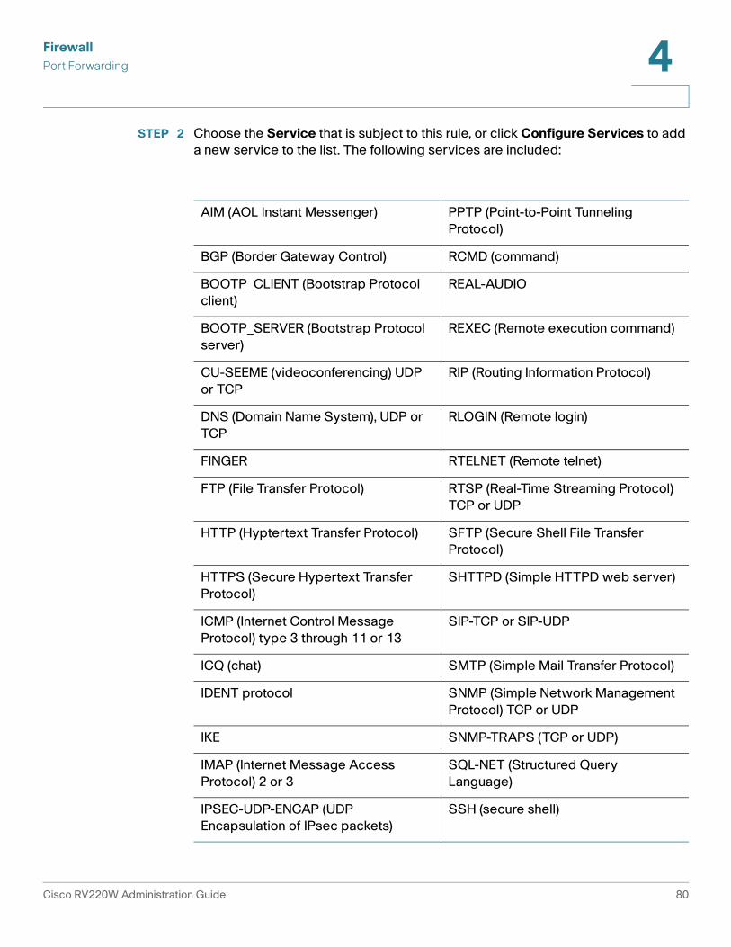
Firewall
Port Forwarding 4
STEP 2 Choose the Service that is subject to this rule, or click Configure Services to add
a new service to the list. The following services are included:
AIM (AOL Instant Messenger) PPTP (Point-to-Point Tunneling
Protocol)
BGP (Border Gateway Control) RCMD (command)
BOOTP_CLIENT (Bootstrap Protocol
client)
REAL-AUDIO
BOOTP_SERVER (Bootstrap Protocol
server)
REXEC (Remote execution command)
CU-SEEME (videoconferencing) UDP
or TCP
RIP (Routing Information Protocol)
DNS (Domain Name System), UDP or
TCP
RLOGIN (Remote login)
FINGER RTELNET (Remote telnet)
FTP (File Transfer Protocol) RTSP (Real-Time Streaming Protocol)
TCP or UDP
HTTP (Hyptertext Transfer Protocol) SFTP (Secure Shell File Transfer
Protocol)
HTTPS (Secure Hypertext Transfer
Protocol)
SHTTPD (Simple HTTPD web server)
ICMP (Internet Control Message
Protocol) type 3 through 11 or 13
SIP-TCP or SIP-UDP
ICQ (chat) SMTP (Simple Mail Transfer Protocol)
IDENT protocol SNMP (Simple Network Management
Protocol) TCP or UDP
IKE SNMP-TRAPS (TCP or UDP)
IMAP (Internet Message Access
Protocol) 2 or 3
SQL-NET (Structured Query
Language)
IPSEC-UDP-ENCAP (UDP
Encapsulation of IPsec packets)
SSH (secure shell)
Cisco RV220W Administration Guide 80
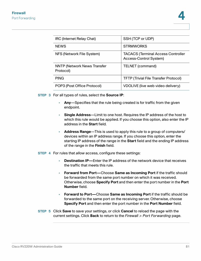
Firewall
Port Forwarding 4
STEP 3 For all types of rules, select the Source IP:
• Any—Specifies that the rule being created is for traffic from the given
endpoint.
• Single Address—Limit to one host. Requires the IP address of the host to
which this rule would be applied. If you choose this option, also enter the IP
address in the Start field.
• Address Range—This is used to apply this rule to a group of computers/
devices within an IP address range. If you choose this option, enter the
starting IP address of the range in the Start field and the ending IP address
of the range in the Finish field.
STEP 4 For rules that allow access, configure these settings:
• Destination IP—Enter the IP address of the network device that receives
the traffic that meets this rule.
• Forward from Port—Choose Same as Incoming Port if the traffic should
be forwarded from the same port number on which it was received.
Otherwise, choose Specify Port and then enter the port number in the Port
Number field.
• Forward to Port—Choose Same as Incoming Port if the traffic should be
forwarded to the same port on the receiving server. Otherwise, choose
Specify Port and then enter the port number in the Port Number field.
STEP 5 Click Save to save your settings, or click Cancel to reload the page with the
current settings. Click Back to return to the Firewall > Port Forwarding page.
IRC (Internet Relay Chat) SSH (TCP or UDP)
NEWS STRMWORKS
NFS (Network File System) TACACS (Terminal Access Controller
Access-Control System)
NNTP (Network News Transfer
Protocol)
TELNET (command)
PING TFTP (Trivial File Transfer Protocol)
POP3 (Post Office Protocol) VDOLIVE (live web video delivery)
Cisco RV220W Administration Guide 81

Firewall
DMZ Host 4
DMZ Host
The Cisco RV220W supports DMZ options. A DMZ is a sub-network that is open
to the public but behind the firewall. DMZ allows you to redirect packets going to
your WAN port IP address to a particular IP address in your LAN. It is
recommended that hosts that must be exposed to the WAN (such as web or email
servers) be placed in the DMZ network. Firewall rules can be allowed to permit
access to specific services and ports to the DMZ from both the LAN or WAN. In
the event of an attack on any of the DMZ nodes, the LAN is not necessarily
vulnerable as well.
You must configure a fixed (static) IP address for the endpoint that will be
designated as the DMZ host. The DMZ host should be given an IP address in the
same subnet as the router's LAN IP address but it cannot be identical to the IP
address given to the LAN interface of this gateway.
To open this page: In the navigation tree, choose Firewall > DMZ Host.
STEP 1 Check the Enable box to enable DMZ on the network. Uncheck the box to disable
this feature.
STEP 2 Enter the IP address for the endpoint that will receive the redirected packets. This
is the DMZ host.
STEP 3 Click Save to save your settings, or click Cancel to reload the page with the
current settings. After enabling a DMZ host, configure firewall rules for the zone.
See Custom Services, page 87.
Advanced Firewall Settings
Use the Advanced Settings menu options to configure the following advanced
firewall settings:
• One-to-One Network Address Translation (NAT), page 83
• MAC Address Filtering, page 85
• IP/MAC Address Binding, page 86
• Custom Services, page 87
• Schedules for Firewall Rules and Port Forwarding Rules, page 89
Cisco RV220W Administration Guide 82

Firewall
Advanced Firewall Settings 4
• Session Settings, page 91
• Internet Group Management Protocol (IGMP), page 92
• SIP ALG, page 93
One-to-One Network Address Translation (NAT)
One-to-one NAT is a mechanism that maps public IP addresses to the private IP
addresses of devices that are behind a firewall.
• Managing One-to-One NAT Rules, page 83
• Adding or Editing a One-to-One NAT Rule, page 84
Managing One-to-One NAT Rules
Use the Firewall > Advanced Settings > One-to-One NAT page to view, add, edit,
and delete One-to-One NAT Rules.
To open this page: In the navigation tree, choose Firewall > Advanced Settings >
One-to-One NAT.
The One-to-One-NAT Rules Table lists the available One-To-One NAT rules that
have been configured. It displays the following fields:
• Private Range Begin—The starting IP address in the private (LAN) IP
address.
• Public Range Begin—The starting IP address in the public (WAN) IP
address.
• Range Length—Range length maps one to one private address to public
address up to the given range.
• Service—Shows configured services. Services for one-to-one NAT allow
you to configure the service to be accepted by the private IP (LAN) address
when traffic is sent to the corresponding public IP address. Configured
services on private IP addresses in the range are accepted when traffic is
available on the corresponding public IP address.
Perform these tasks:
• To add a one-to-one NAT rule, click Add. Then enter the settings on the Add/
Edit One-to-One NAT Configuration page. See Adding or Editing a One-to-
One NAT Rule, page 84.
Cisco RV220W Administration Guide 83

Firewall
Advanced Firewall Settings 4
• To edit a one-to-one NAT rule, check the box and then click Edit. Then enter
the settings on the Add/Edit One-to-One NAT Configuration page. See
Adding or Editing a One-to-One NAT Rule, page 84.
• To delete a one-to-one NAT rule, check the box and then click Delete. To
select all rules, check the box in the heading row, and then click Delete.
When the confirmation message appears, click OK to continue with the
deletion, or otherwise click Cancel.
Adding or Editing a One-to-One NAT Rule
Use the Add/Edit One-to-One NAT Configuration page to map a private IP
address or range to a public IP address or range.
To open this page: From the Firewall > Advanced Settings > One-to-One NAT
page, click Add or select a rule and then click Edit.
STEP 1 Enter this information:
• Private Range Begin—The starting IP address in the private (LAN) IP
address.
• Public Range Begin—The starting IP address in the public (WAN) IP
address.
• Range Length—Range length maps one to one private address to public
address up to the given range.
• Service—Choose the service for which the rule applies.
STEP 2 Click Save to save your settings, or click Cancel to reload the page with the
current settings. Click Back to return to the Firewall > Advanced Settings > One-
to-One NAT page.
Cisco RV220W Administration Guide 84

Firewall
Advanced Firewall Settings 4
MAC Address Filtering
Use the Firewall > Advanced Settings > MAC Filtering page to allow or block
traffic from certain known machines or devices. The router uses the MAC address
of a computer or device on the network to identify it and permit or deny access.
Traffic from a specified MAC address will be filtered depending upon the policy.
NOTE The MAC filtering policy does not override a firewall rule that directs incoming
traffic to a host.
To open this page: In the navigation tree, choose Firewall > Advanced Settings >
MAC Filtering.
The MAC Address Table lists the MAC addresses and descriptions for all devices
that are subject to the MAC filtering policy.
STEP 1 In the MAC Filtering Settings section, enter these settings:
• Source MAC Address Filtering—Check the Enable box to enable MAC
Address Filtering for this device. Uncheck the box to disable this feature.
After changing this setting, click Save to save your settings, or click Cancel
to reload the page with the current settings. Enabling this feature makes
other fields available.
• Policy for MAC Addresses Listed Below—If you enabled MAC filtering,
choose one of the following options:
- Block and Allow the Rest—Choose this option to block the traffic from
the specified MAC addresses and to allow traffic from all other
addresses.
- Allow and Block the Rest—Choose this option to allow the traffic from
the specified MAC addresses and to block traffic from all other machines
on the LAN side of the router.
For example, two computers are on the LAN with MAC addresses of
00:01:02:03:04:05 (host1), and 00:01:02:03:04:11 (host2). If the host1 MAC
address is added to the MAC filtering list and the “block and allow the
rest” policy is chosen, when this computer tries to connect to a website,
the router will not allow it to connect. However, host2 is able to connect
because its MAC address is not in the list. If the policy is “allow and block
the rest,” then host1 is allowed to connect to a website, but host2 is
blocked because its URL is not in the list.
Cisco RV220W Administration Guide 85

Firewall
Advanced Firewall Settings 4
STEP 2 In the MAC Addresses Table, perform these tasks:
• To add a new entry, click Add. Enter the 12-character MAC Address without
punctuation. The formatting is applied automatically. Optionally, type a
Description for your reference.
• To delete an entry, check the box and then click Delete. To select all entries,
check the box in the heading row.
STEP 3 After making changes, click Save to save your settings, or click Cancel to reload
the page with the current settings.
IP/MAC Address Binding
Use the Firewall > Advanced Settings > IP/MAC Binding page to bind IP
addresses to MAC addresses. This feature is useful if you have configured a
machine with a static address and want to discourage a user from changing the IP
address. If a specified device sends packets using an unexpected IP address, the
Cisco RV220W drops the packets.
To open this page: In the navigation tree, choose Firewall > Advanced Settings >
IP/MAC Binding.
The IP/MAC Binding Table lists the names, MAC addresses, and IP addresses for
the currently defined IP/MAC binding rules.
STEP 1 Perform these tasks:
• To add a new entry, click Add. Enter these settings:
- Name—Enter a short description for your reference.
- MAC Address—Enter the 12-character MAC address of the device
without punctuation. The formatting is applied automatically.
- IP Address—Enter the expected IP address of the specified device.
• To edit an entry, check the box and then click Edit. To select all entries, check
the box in the heading row. Edit the information, as described above.
• To delete an entry, check the box and then click Delete. To select all entries,
check the box in the heading row.
Cisco RV220W Administration Guide 86
Firewall
Advanced Firewall Settings 4
STEP 2 After making changes, click Save to save your settings, or click Cancel to reload
the page with the current settings.
Custom Services
Each firewall rule applies to a specific type of service. Common types of services
are pre-configured and can be selected from the Service list when you configure
an access rule. (See Adding and Editing Access Rules, page 67.) As needed, you
can add services to the list.
• Managing Custom Services, page 87
• Adding or Editing a Custom Service, page 88
Managing Custom Services
Use the Firewall > Advanced Settings > Custom Services page to view, add, edit,
or delete custom services.
NOTE For a list of pre-configured services, see the Service description in the procedure
Adding and Editing Access Rules, page 67.
To open this page: In the navigation tree, choose Firewall > Advanced Settings >
Custom Services.
The Custom Services Table lists the details for the custom services that have
been defined.
Perform these tasks:
• To add a service, click Add. Then enter the settings on the Add/Edit Custom
Services Configuration page. See Adding or Editing a Custom Service,
page 88.
• To edit a service, check the box and then click Edit. Then enter the settings
on the Add/Edit Custom Services Configuration page. See Adding or
Editing a Custom Service, page 88.
• To delete a service, check the box and then click Delete. To select all
services, check the box in the heading row, and then click Delete. When the
confirmation message appears, click OK to continue with the deletion, or
otherwise click Cancel.
Cisco RV220W Administration Guide 87

Firewall
Advanced Firewall Settings 4
Adding or Editing a Custom Service
Use the Add/Edit Custom Services Configuration page to enter the settings for a
custom service.
To open this page: From the Firewall > Advanced Settings > Custom Services
page, click Add or select a service and then click Edit.
STEP 1 Enter these settings:
• Name—Enter a service name for identification and management purposes.
• Type—Choose layer 4 protocol that the service uses (TCP, UDP, ICMP,
ICMPv6, or other).
- If you chose ICMP or ICMPv6 as the service type, specify the ICMP type
by entering its numeric value (from 0 through 40 for ICMP and from 0
through 255 for ICMPv6).
- If you chose TCP or UDP, enter the first TCP or UDP port of the range that
the service uses. In the Finish Port field, enter the last TCP or UDP port
of the range that the service uses.
- If you chose Other, enter the number of the protocol in the Protocol
Number field. (For example, if you are using RDP, enter 27 in the protocol
number field.)
STEP 2 Click Save to save your settings, or click Cancel to reload the page with the
current settings. Click Back to return to the Firewall > Advanced Settings >
Custom Services page.
Cisco RV220W Administration Guide 88

Firewall
Advanced Firewall Settings 4
Schedules for Firewall Rules and Port Forwarding Rules
You can create schedules to activate firewall access rules and port forwarding
rules on specific days or at specific times of the day.
• Managing Schedules, page 89
• Adding or Editing a Schedule, page 90
Managing Schedules
Use the Firewall > Advanced Settings > Schedules page to view, add, edit, or
delete schedules.
To open this page: In the navigation tree, choose Firewall > Advanced Settings >
Schedules.
• To add a schedule, click Add. Then enter the settings on the Add/Edit
Schedules Configuration page. See Adding or Editing a Schedule,
page 90.
• To edit a schedule, check the box and then click Edit. Then enter the
settings on the Add/Edit Schedules Configuration page. See Adding or
Editing a Schedule, page 90.
• To delete a schedule, check the box and then click Delete. To select all
schedules, check the box in the heading row, and then click Delete. When
the confirmation message appears, click OK to continue with the deletion,
or otherwise click Cancel.
Cisco RV220W Administration Guide 89
Firewall
Advanced Firewall Settings 4
Adding or Editing a Schedule
Use the Add/Edit Schedules Configuration page to configure a schedule for a
firewall access rule or a port forwarding rule.
To open this page: From the Firewall > Advanced Settings > Schedules page,
click Add or select a schedule and then click Edit.
STEP 1 Enter these settings:
• Name—Enter a unique name to identify the schedule in the Schedule Table
on the Firewall > Advanced Settings > Schedules page.
• Time—Choose one of the following options:
- If this schedule applies to the entire day, check the All Day box.
- If this schedule applies during specified hours of the day, uncheck the All
Day box. Then enter the Start Time and End Time by choosing the
Hours, Minutes, and time period (AM or PM). The schedule will become
active at the specified start time and will become inactive at the
specified end time on the selected day(s).
• Repeat—Choose one of the following options:
- If this schedule applies to all the days of the week, check the Everyday
box.
- If this schedule applies only on specified days, uncheck the Everyday
box. Then check the box for each day when the schedule is active.
Uncheck the box for each day when the schedule is inactive.
STEP 2 Click Save to save your settings, or click Cancel to reload the page with the
current settings. Click Back to return to the Firewall > Advanced Settings >
Schedules page.
Cisco RV220W Administration Guide 90

Firewall
Advanced Firewall Settings 4
Session Settings
Use the Firewall > Advanced Settings > Session Settings page to limit the
maximum number of unidentified sessions and half-open sessions on the Cisco
RV220W. You can also introduce timeouts for TCP and UDP sessions to ensure
that Internet traffic is not deviating from expectations in your private network.
To open this page: In the navigation tree, choose Firewall > Advanced Settings >
Session Settings.
STEP 1 Enter these settings:
• Maximum Unidentified Sessions—Enter the maximum number of
unidentified sessions for the ALG identification process. This value can
range from 2 through 128. The default is 32 sessions.
• Maximum Half Open Sessions—Enter the maximum number of half-open
sessions. A half-open session is the session state between receipt of a SYN
packet and the SYN/ACK packet. Under normal circumstances, a session is
allowed to remain in the half-open state for 10 seconds. The maximum value
ranges from 0 through 3,000. The default is 128 sessions.
• TCP Session Timeout Duration—Enter the time, in seconds, after which
inactive TCP sessions are removed from the session table. Most TCP
sessions terminate normally when the RST or FIN flags are detected. This
value ranges from 0 through 4,294,967 seconds. The default is 1,800
seconds (30 minutes).
• UDP Session Timeout Duration—Enter the time, in seconds, after which
inactive UDP sessions are removed from the session table. This value ranges
from 0 through 4,294,967 seconds. The default is 120 seconds (2 minutes).
• Other Session Timeout Duration (seconds)—Enter the time, in seconds,
after which inactive non-TCP/UDP sessions are removed from the session
table. This value ranges from 0 through 4,294,967 seconds. The default is 60
seconds.
• TCP Session Cleanup Latency (seconds)—Enter the maximum time for a
session to remain in the session table after detecting both FIN flags. This
value ranges from 0 through 4,294,967 seconds. The default is 10 seconds.
STEP 2 Click Save to save your settings, or click Cancel to reload the page with the
current settings.
Cisco RV220W Administration Guide 91

Firewall
Advanced Firewall Settings 4
Internet Group Management Protocol (IGMP)
Use the Firewall > Advanced Settings > IGMP Configuration page to enable the
IGMP Proxy on the LAN or WAN interface. Internet Group Management Protocol
(IGMP) is an exchange protocol for routers. Hosts that want to receive multicast
messages need to inform their neighboring routers of their status. In some
networks, each node in a network becomes a member of a multicast group and
receives multicast packets. In these situations, hosts exchange information with
their local routers by using IGMP. Routers use IGMP periodically to check if the
known group members are active. IGMP provides a method called dynamic
membership by which a host can join or leave a multicast group at any time.
• Enabling IGMP and Managing the Allowed Networks Table, page 92
• Adding or Editing the Allowed Networks, page 93
Enabling IGMP and Managing the Allowed Networks Table
Use the Firewall > Advanced Settings > IGMP Configuration page to enable or
disable the IGMP Proxy and to view, add, edit, or delete the allowed networks.
To open this page: In the navigation tree, choose Firewall > Advanced Settings >
IGMP Configuration.
The Allowed Networks Table lists all the allowed networks configured for the
device and allows several operations on the allowed networks:
• Network Address—Enter the IP address of the network.
• Mask Length—Enter the number of masked bits, as in CIDR slash notation.
Valid values are from 0 to 32.
NOTE By default the device will forward multicast packets which are originating from its
immediate WAN network.
STEP 1 In the IGMP Configuration section, enter these settings:
• IGMP Proxy—Check the Enable box to allow IGMP communication
between the router and other nodes in the network. Otherwise, uncheck the
box.
• Upstream Interface—Choose WAN or LAN to specify the interface on
which the IGMP proxy acts as a multicast client.
• After enabling or disabling the proxy, click Save to save your settings or click
Cancel to reload the page with the current settings. Other features become
available on the page when IGMP Proxy is enabled.
Cisco RV220W Administration Guide 92

Firewall
Advanced Firewall Settings 4
STEP 2 In the Allowed Networks Table, perform these tasks:
• To add a network, click Add. Then enter the settings on the Add/Edit
Networks page. See Adding or Editing the Allowed Networks, page 93.
• To edit a network, check the box and then click Edit. Then enter the settings
on the Add/Edit Networks page. See Adding or Editing the Allowed
Networks, page 93.
• To delete a network, check the box and then click Delete. To select all
networks, check the box in the heading row, and then click Delete. When the
confirmation message appears, click OK to continue with the deletion, or
otherwise click Cancel.
Adding or Editing the Allowed Networks
Use the Add/Edit Networks page to specify the allowed networks for IGMP
communications.
To open this page: From the Firewall > Advanced Settings > IGMP Configuration
page, click Add or select a network and then click Edit.
STEP 1 Enter these settings:
• Network Address—Enter the IP address of the network.
• Mask Length—Enter the number of masked bits, as in CIDR slash notation.
Valid values are from 0 to 32.
STEP 2 Click Save to save your settings, or click Cancel to reload the page with the
current settings. Click Back to return to the Firewall > Advanced Settings > IGMP
Configuration page.
SIP ALG
Session Initiation Protocol Application-Level Gateway (SIP ALG) can rewrite
information within SIP messages (SIP headers and SDP body) to allow signaling
and audio traffic between a client on your private network and a SIP endpoint.
To open this page: In the navigation tree, choose Firewall > Advanced Settings >
SIP ALG.
Cisco RV220W Administration Guide 93

Firewall
Firewall Configuration Examples 4
STEP 1 Check the Enable box to enable SIP ALG support. If disabled, the router will not
allow incoming calls to the UAC (User Agent Client) behind the Cisco RV220W.
STEP 2 Click Save to save your settings, or click Cancel to reload the page with the
current settings.
Firewall Configuration Examples
Example 1: Allow inbound HTTP traffic to the DMZ
In this example, you host a public web server on your local DMZ network. You
want to allow inbound HTTP requests from any outside IP address to the IP
address of your web server at any time of day.
Create an inbound rule as follows:
Example 2: Allow videoconferencing from range of outside IP addresses.
In this example, you want to allow incoming videoconferencing to be initiated from
a restricted range of outside IP addresses (132.177.88.2 - 132.177.88.254), from a
branch office.
Create an inbound rule as follows. In the example, CUSeeMe connections are
allowed only from a specified range of external IP addresses.
Parameter Value
Connection Type Inbound
Action Always Allow
Service HTTP
Source IP Any
Send to Local Server (DNAT IP) 192.168.5.2 (web server IP address)
Rule Status Enabled
Cisco RV220W Administration Guide 94

Firewall
Firewall Configuration Examples 4
Example 3: Multi-NAT Configuration
In this example, you want to configure multi-NAT to support multiple public IP
addresses on one WAN port interface.
Create an inbound rule that configures the firewall to host an additional public IP
address. Associate this address with a web server on the DMZ. If you arrange with
your ISP to have more than one public IP address for your use, you can use the
additional public IP addresses to map to servers on your LAN. One of these public
IP addresses is used as the primary IP address of the router. This address is used
to provide Internet access to your LAN PCs through NAT. The other addresses are
available to map to your DMZ servers.
The following addressing scheme is used to illustrate this procedure:
• WAN IP address: 10.1.0.118
• LAN IP address: 192.168.1.1; subnet 255.255.255.0
• Web server PC in the DMZ, IP address: 192.168.1.2
• Access to Web server: (simulated) public IP address 10.1.0.52
Parameter Value
Connection Type Inbound
Action Always Allow
Service CU-SEEME:UDP
Source IP Address Range
Start 132.177.88.2
Finish 134.177.88.254
Send to Local Server (DNAT IP) 192.168.1.11
Rule Status Enabled
Cisco RV220W Administration Guide 95

Firewall
Firewall Configuration Examples 4
Example 4: Block traffic by schedule if generated from specific range of
machines
In this example, you want to block all HTTP traffic on the weekends if the request
originates from a specific group of machines in the LAN having a known range of
IP addresses, and anyone coming in through the Network from the WAN (i.e. all
remote users).
For this example, use the Firewall > Advanced Settings > Schedules page to add
a schedule that is active all day on Saturday and Sunday. For more information, see
Schedules for Firewall Rules and Port Forwarding Rules, page 89.
Then create the outbound and inbound access rules as shown below.
Create an outbound access rule with the following parameters:
Parameter Value
Connection Type Inbound
Action Always Allow
Service HTTP
Source IP Single Address
Start 10.1.0.52
Send to Local Server (DNAT IP) 192.168.1.2 (local IP address of your web server)
Rule Status Enabled
Parameter Value
Connection Type Outbound
Action Block by Schedule
Schedule Weekend
Service HTTP
Source IP Address Range
Cisco RV220W Administration Guide 96

Firewall
Firewall Configuration Examples 4
Create an inbound access rule with the following parameters:
Start starting IP address
Finish ending IP address
Destination IP Any
Rule Status Enabled
Parameter Value
Parameter Value
Connection Type Inbound
Action Block by Schedule
Schedule Weekend
Service All Traffic
Source IP Any
Rule Status Enabled
Cisco RV220W Administration Guide 97

5
Cisco ProtectLink Web
The optional Cisco ProtectLink Web service provides security for your network. It
filters website addresses (URLs) and blocks potentially malicious websites.
Refer to these topics:
• Getting Started with Cisco ProtectLink Web, page 98
• Global Settings for Approved URLs and Clients, page 99
• Web Protection, page 101
• Updating the ProtectLink License, page 104
NOTE For more information about this Cisco product, visit the Cisco ProtectLink Web
information page at www.cisco.com/en/US/products/ps9953/index.html
Getting Started with Cisco ProtectLink Web
You can purchase, register, and activate the service by using the links on the Cisco
ProtectLink Web page.
To open this page: In the navigation tree, click Cisco ProtectLink Web.
Choose the appropriate option:
• Learn more about and request Free Trial for Cisco ProtectLink—Click
this link to open the Cisco ProtectLink Security Solutions page on
Cisco.com. You can read product information and get a 30-day trial for your
RV router.
• Register ProtectLink services and obtain an Activation Code (AC)—
Click this link if you purchased the product and are ready to register it.
When the registration page appears, follow the on-screen instructions to
enter your Registration Key and provide the required information. Close the
web page when you complete this process. The activation code will
Cisco RV220W Administration Guide 98

Cisco ProtectLink Web
Global Settings for Approved URLs and Clients 5
appear on the screen and will be sent to the email address that you
provided.
• Use the Activation Code (AC) to activate ProtectLink services—Click
this link if you registered the product and received an activation code. When
the activation page appears, enter your activation code and follow the on-
screen instructions to proceed. Close the web page when you complete
this process. Refresh the web browser, and now the ProtectLink Web
features are available on your router. The Global Settings page appears.
NOTE If you replace one router with another router that supports this service, you can use
the Use the Activation Code link to transfer your license for the ProtectLink service
to the new router.
Global Settings for Approved URLs and Clients
After you activate your service, you can use the Cisco ProtectLink Web > Global
Settings page to configure the approved clients and approved URLs that are free
from the restrictions that you establish for website access.
• Approved Clients, page 99
• Approved URLs, page 100
Approved Clients
Use the Cisco ProtectLink Web > Global Settings > Approved Clients page to
specify approved clients that are not subject to the restrictions that you configure
in Web Protection. Web Protection will not restrict URL requests from these IP
addresses.
To open this page: In the navigation tree, choose Cisco ProtectLink Web >
Global Settings > Approved Clients.
NOTE This page is available only if you activated your Cisco ProtectLink Web service. See
Getting Started with Cisco ProtectLink Web, page 98.
Cisco RV220W Administration Guide 99

Cisco ProtectLink Web
Global Settings for Approved URLs and Clients 5
STEP 1 In the Approved Clients section, check the Enable box to enable this feature.
STEP 2 In the Approved Clients Table, specify the clients that will always have access to
all URLs, regardless of Web Protection settings.
• To add an entry, click Add. On the Approved Client IP Configuration page,
enter IP addresses or ranges. To enter non-consecutive IP addresses, type
a semi-colon between entries, such as 10.1.1.1;10.1.1.5. To enter a range of IP
addresses, type a hyphen between the first and last address in the range,
such as 10.1.1.0-10.1.1.10. Click Save to save your settings.
• To edit an entry, check a box, and then click Edit. Enter and save the settings,
as described above.
• To delete an entry, check a box, and then click Delete. To select all entries in
the table, check the box in the heading row and then click Delete.
STEP 3 Click Save to save your settings, or click Cancel to reload the page with the
current settings.
Approved URLs
Use the Cisco ProtectLink Web > Global Settings > Approved URLs page to
specify approved URLs that the users are always able to access. Web Protection
will not restrict access to these domains.
To open this page: In the navigation tree, choose Cisco ProtectLink Web >
Global Settings > Approved Clients.
NOTE This page is available only if you activated your Cisco ProtectLink Web service. See
Getting Started with Cisco ProtectLink Web, page 98.
STEP 1 In the Approved URLs section, check the Enable box to enable this feature. The
specified URLs will always be accessible.
STEP 2 In the Approved URLs Table, specify the URLs that are always accessible,
regardless of Web Protection settings.
• To add an entry, click Add. On the Approved URL Configuration page. Enter
the trusted URL(s) in the box. To enter multiple URLs, type a semi-colon
between entries, such as www.cisco.com;www.google.com;
www.mycompany.com. All pages in the specified domains will be
Cisco RV220W Administration Guide 100

Cisco ProtectLink Web
Web Protection 5
accessible. Click Save to save your changes. If you entered any invalid
characters, a message appears. Click OK to close the message, and edit
your entries. Spaces, commas, and symbols are not allowed.
• To edit an entry, check a box, and then click Edit. Enter and save the settings,
as described above.
• To delete an entry, check a box, and then click Delete. To select all entries in
the table, check the box in the heading row and then click Delete.
STEP 3 Click Save to save your settings, or click Cancel to reload the page with the
current settings.
Web Protection
Web Protection includes these features:
• Overflow Control, page 101
• Web Reputation, page 102
• URL Filtering, page 103
Overflow Control
Use the Cisco ProtectLink Web > Web Protection > Overflow Control page to
control how excess URL requests are handled.
To open this page: In the navigation tree, choose Cisco ProtectLink Web > Web
Protection > Overflow Control.
NOTE This page is available only if you activated your Cisco ProtectLink Web service. See
Getting Started with Cisco ProtectLink Web, page 98.
STEP 1 Enter these settings:
• Temporarily block URL requests: Users will not be able to access the
Internet until the current queue can accommodate more requests. This
setting is recommended.
Cisco RV220W Administration Guide 101

Cisco ProtectLink Web
Web Protection 5
• Temporarily bypass Cisco ProtectLink URL Filtering for requested URLs:
URL requests will temporarily bypass URL Filtering and Web Reputation.
This setting could make your network vulnerable to threats.
STEP 2 Click Save to save your settings, or click Cancel to reload the page with the
current settings.
Web Reputation
Use the Cisco ProtectLink Web > Web Protection > Web Reputation page to
enable and configure Web Reputation. When this feature is enabled, Requested
URLs are checked against the set security level and the Trend Micro Web Security
database in real-time. Only URLs that meet the criteria are accessible.
To open this page: In the navigation tree, choose Cisco ProtectLink Web > Web
Protection > Web Reputation.
NOTE This page is available only if you activated your Cisco ProtectLink Web service. See
Getting Started with Cisco ProtectLink Web, page 98.
STEP 1 In the Web Reputation section, check the Enable box to enable this feature.
Uncheck the box to disable it.
STEP 2 In the Security Level section, choose one of these options:
• High—This option blocks a higher number of potentially malicious websites,
but also has a higher incidence of false positives (legitimate sites that are
classified as malicious).
• Medium—This option blocks most potentially malicious websites, and has a
lower incidence of false positives (legitimate sites that are classified as
malicious). This setting is recommended.
• Low: This option blocks fewer potentially malicious websites, and therefore
reduces the risk of false positives.
STEP 3 Click Save to save your settings, or click Cancel to reload the page with the
current settings.
Cisco RV220W Administration Guide 102
Cisco ProtectLink Web
Web Protection 5
URL Filtering
Use the Cisco ProtectLink Web > Web Protection > URL Filtering page to control
requests to web sites based on categories and the time of request.
To open this page: In the navigation tree, click Cisco ProtectLink Web > Web
Protection > URL Filtering.
NOTE This page is available only if you activated your Cisco ProtectLink Web service. See
Getting Started with Cisco ProtectLink Web, page 98.
STEP 1 In the URL Filtering section, enter these settings:
• URL Filtering: Check the Enable box to block access to websites based on
pre-defined categories and the time of the request. Uncheck the box to
disable this feature.
• Enable Check Referer: Check the box to enable checking the HTTP referer
header for allowed URLs. When enabled, this feature allows a user to access
a link on an allowed web page even if the link goes to a different domain.
• HTTP Ports—Enter the HTTP ports to which content filtering applies. The
default port is 80. If your networking using an external HTTP proxy server
which listens on other ports, they can be added here. Multiple ports can be
specified in a comma separated list.
STEP 2 In the Filtered Categories table, select the categories and sub-categories for
websites that you want to block during Business Hours and Leisure Hours.
Note: The Business Hours and Leisure Hours are defined by the Business Days
and Business Times settings.
• To view sub-categories under a category, click the plus sign (+).
• To block access for all sub-categories within a category, check the box for
the category. To disable filtering for a category, uncheck the box.
• To block access for an individual sub-category, check the box. To disable
filtering for a sub-category, uncheck the box.
• For each filter that you enable, the Instances Blocked column will display the
number of times that someone attempted to visit a blocked site. YOu can
click Reset Counters to reset the counter to zero.
Cisco RV220W Administration Guide 103

Cisco ProtectLink Web
Updating the ProtectLink License 5
STEP 3 In the Business Days and Business Times sections, choose days and times to
define your Business Hours for the Filtered Categories table. The unselected days
and times define the Leisure Hours in the table.
• Business Days: Check the box for each day when your business is open.
Uncheck the box for each day when your business is closed. On the checked
days, the Business Hours filters apply. On the unchecked days, the Leisure
Hours filters apply.
• Business Times: To use the same settings all day, choose All day (24 hours).
To specify the hours when your business is open, click Specify business
Hours. Check the Morning box and select the From and To times. Then
check the Afternoon box and select the From and To times. During the
selected periods, the Business Hours filters apply. During all other periods,
the Leisure Hours filters apply.
STEP 4 Click Save to save your settings, or click Cancel to reload the page with the
current settings.
Updating the ProtectLink License
You can view your license information and renew your license.
• Summary, page 104
• Renewal, page 105
Summary
Use the Cisco ProtectLink Web > License > Summary page to view your license
information.
To open this page: In the navigation tree, click Cisco ProtectLink Web > License
> Summary.
NOTE This page is available only if you activated your Cisco ProtectLink Web service. See
Getting Started with Cisco ProtectLink Web, page 98.
To refresh the license information displayed on this page, click Update
Information.
Cisco RV220W Administration Guide 104

Cisco ProtectLink Web
Updating the ProtectLink License 5
The License Information section displays the following information:
• View detailed license online: To view license information online, click this
link. Your web browser opens the ProtectLink Product Detail page. You can
close that page when you finish reading the information.
• Status: The status of your license: Activated or Expired
• Platform: The platform type, Gateway Service.
• License expires on: The date and time your license when the license
expires (one year after the service was activated)
Renewal
Use the Cisco ProtectLink Web > License > Renewal page to view information
about renewing your license. Follow the instructions to purchase and register your
registration key and to use your activation code to enable Protect Link services on
the Cisco RV220W.
To open this page: In the navigation tree, click Cisco ProtectLink Web > License
> Renewal.
Cisco RV220W Administration Guide 105

6
Configuring Virtual Private Networks (VPNs) and Security
This chapter explains how to configure virtual private networks for secure access
to your network resources.
The following sections are covered:
• Configuring VPNs, page 107
• Basic VPN Setup, page 109
• Configuring Advanced VPN Parameters, page 111
• SSL VPN Server, page 124
• SSL VPN Tunnel Client Configuration, page 136
Cisco RV220W Administration Guide 106

Configuring Virtual Private Networks (VPNs) and Security
Configuring VPNs 6
Configuring VPNs
A VPN provides a secure communication channel (“tunnel”) between two gateway
routers or a remote worker and a gateway router. You can create different types of
VPN tunnels, depending on the needs of your business. Several scenarios are
described below. Read these descriptions to understand the options and the
steps required to set up your VPN.
• Site-to-Site Access with Gateway-to-Gateway VPN, page 107
• Remote Access with an IPsec Client (Client-to-Gateway VPN), page 107
• Remote Access with Clientless SSL VPN, page 108
• Remote Access with Cisco QuickVPN, page 109
• Remote access using PPTP, page 109
Site-to-Site Access with Gateway-to-Gateway VPN
A gateway-to-gateway VPN connects two or more routers using an IPsec policy to
secure traffic between two sites. Use this type of VPN if you need to connect the
network at a branch office to the network at your main office, for example.
1. Use the Basic VPN Setup page to create a VPN. Choose Gateway as the peer type, and enter a connection name, pre-shared key, remote gateway, local gateway (should be pre-populated), remote LAN, and local LAN. You will need to configure the corresponding settings on the router at the other site. See Basic VPN Setup, page 109.
2. If needed, edit the default settings by using the Advanced VPN Setup page. See Configuring Advanced VPN Parameters, page 111.
Remote Access with an IPsec Client (Client-to-Gateway VPN)
In this scenario, a remote client, such as a PC running IPsec VPN client software,
initiates a VPN tunnel. The IP address of the remote PC client is not necessarily
known in advance. The gateway acts as responder. Configure this type of VPN
tunnel if you have a teleworkers who need to securely connect to your network
from their home offices, for example.
You will need to configure this router with the specific IPsec policies required for
the IPsec client. You also will need to install and configure the IPsec client
software on the users’ computers.
Cisco RV220W Administration Guide 107

Configuring Virtual Private Networks (VPNs) and Security
Configuring VPNs 6
1. Use the Basic VPN Setup page to quickly configure the IKE Policy and the VPN Policy by using the standard settings. Choose VPN Client as the peer type, and enter the other basic settings. Note that the users’ VPN client software will need to be configured with the same Pre-Shared Key that you enter here. See Basic VPN Setup, page 109.
2. To configure the settings required by the VPN client software, use the Advanced VPN Setup page to edit the IKE Policy and the VPN Policy. For the required settings, refer to the VPN client documentation. See Configuring Advanced VPN Parameters, page 111.
3. Set up the users:
• If you configured the VPN policy to authenticate from the local database,
add the users on the VPN > IPsec > VPN Users page. Choose XAUTH as
the user protocol. (See Configuring VPN Users, page 122).
• If you configured the VPN policy to authenticate from an external database,
configure the connection to the RADIUS server. See Using the Cisco
RV220W With a RADIUS Server, page 146.
Remote Access with Clientless SSL VPN
SSL VPN is a flexible and secure way to extend network resources to virtually any
remote user who has access to the Internet and a Web browser. A benefit is that
you do not have to install and maintain VPN client software on the remote
computers. Users connect to a portal that enables access to network resources.
You can set up different portal layouts to be used by different types of users. You
can streamline the setup process by organizing VPN users into domains and
groups that share VPN policies.
1. Create SSL VPN users on the Adminstration > User Management > Users page. You can assign users to the default SSL VPN group. For more information, see User Management, page 158.
2. From a PC on the remote site, open your web browser and attempt to connect to the default portal (https://<wan_ip_address>/portal/SSLVPN). For more information on customizing portals and configuring other advance SSL VPN server features, see SSL VPN Server, page 124.
3. After connecting to the VPN portal, navigate to the VPN tunnel page and launch the SSL VPN Tunnel client installer/launcher. For information about configuring advanced features, see SSL VPN Tunnel Client Configuration, page 136.
NOTE To enable SSL VPN access on this router, you must enable remote management to
open the port used for VPN. See Remote Management, page 157.
Cisco RV220W Administration Guide 108

Configuring Virtual Private Networks (VPNs) and Security
Basic VPN Setup 6
Remote Access with Cisco QuickVPN
For quick setup with basic VPN security settings, distribute Cisco QuickVPN
software to your users, who can then securely access your network resources.
Use this option if you want to simplify the VPN setup process. You do not have to
configure VPN policies. Remote users can connect securely with the Cisco
QuickVPN client and an Internet connection.
1. Add the users on the VPN > IPsec > VPN Users page. Choose QVPN as the user protocol. See Configuring VPN Users, page 122.
2. Instruct users to obtain the free Cisco QuickVPN software from Cisco.com, and install it on their computers. For more information, see .Appendix B, “Using Cisco QuickVPN.”Note: To enable access via Cisco QuickVPN this router, you must enable remote management to open port 443 for SSL. See Remote Management, page 157.
Remote access using PPTP
In this scenario, a remote user with a Microsoft computer connects to a PPTP
server at your site to access network resources. Use this option to simplify VPN
setup. You do not have to configure VPN policies. Remote users can connect by
using the PPTP client from a Microsoft computer. There is no need to install a VPN
client. However, be aware that security vulnerabilities have been found in this
protocol.
Enter the PPTP server settings and add the users on the VPN > IPsec > VPN
Users page. Choose PPTP as the user protocol. See Configuring VPN Users,
page 122.
Basic VPN Setup
Use the Basic VPN Setup page to create a VPN. This feature acts like a VPN setup
wizard to set up a VPN by using a Pre-shared Key (PSK) and default values as
proposed by the VPN Consortium (VPNC). To view the settings that are configured
through this process, click the View Default Settings button. The settings cannot
be changed from this page, but can be configured through the Advanced VPN
Setup page. For more information, see Configuring Advanced VPN Parameters,
page 111.
To open this page: In the navigation tree, choose VPN > IPsec > Basic VPN
Setup.
Cisco RV220W Administration Guide 109

Configuring Virtual Private Networks (VPNs) and Security
Basic VPN Setup 6
STEP 1 Choose the type of peer that the VPN tunnel will connect:
• Gateway—Connects the Cisco RV220W to a gateway, such as another
Cisco RV220W at another site.
• VPN Client—Connects the Cisco RV220W to remote clients. The remote
clients must run VPN client software.
STEP 2 In the Connection Name and Remote IP Type section, enter the following
information:
• New Connection Name—Enter a name to identify this connection. The
connection name is used for management.
• Pre-Shared Key—Enter an alpha-numeric key to be used when setting up a
connection. Include 8 to 49 characters. The double-quote character is not
allowed. Ensure that the VPN client or remote gateway is configured with this
key.
STEP 3 In the Endpoint Information section, enter the following information:
• Remote Gateway Type—If the peer is a gateway, choose a method for
identifying the remote router. You can use either an IP address or a Fully-
Qualified Domain Name. You must configure the same type for the remote
gateway and the local gateway.
• Remote WANs IP Address / FQDN—Enter one of the following options:
- For a gateway-to-gateway connection: If known, enter the remote
router’s IP address or its domain name (for example,
MyServer.MyDomain.com). If you do not have that information, keep the
default setting, remote.com.
- For a client-to-gateway connection: Keep the default setting,
remote.com, specify a client WAN IP address/FQDN if you want to
restrict access only to clients from that site.
• Local Gateway Type—Choose a method for identifying this router. You can
use either an IP address or a Fully-Qualified Domain Name. If the peer is a
gateway, choose the same type that you chose for the Remote Gateway
Type above.
• Local WANs IP Address / FQDN—Based on the above selection, enter
either this router’s IP address or its domain name (for example,
MyServer.MyDomain.com). This field can be left blank if you want to use the
same FQDN or IP address that is specified in the WAN configuration. If you
do not know the address, keep the default setting, local.com.
Cisco RV220W Administration Guide 110

Configuring Virtual Private Networks (VPNs) and Security
Configuring Advanced VPN Parameters 6
STEP 4 In the Secure Connection Remote Accessibility section, enter the following
information:
• Remote LAN (Local Network) IP Address (for a Gateway only)—Enter the
subnet IP address of the remote LAN. A subnet IP address is one that gives
the “network number” of the IP range. For example, a network address of
192.168.1.10 with a Subnet Mask of 255.255.255.0 would have a network
number or subnet IP address of 192.168.1.0.
• Remote LAN (Local Network) Subnet Mask (for a Gateway only)—Enter
the associated Subnet Mask for the remote LAN.
• Local LAN (Local Network) IP Address—Enter the subnet IP address of
the local LAN. A subnet IP address is one that gives the “network number” of
the IP range. For example, a network address of 192.168.1.10 with a Subnet
Mask of 255.255.255.0 would have a network number or subnet IP address
of 192.168.1.0.
• Local LAN (Local Network) Subnet Mask—Enter the Subnet Mask for the
local LAN.
Note: The IP address range used on the remote LAN must be different from
the IP address range used on the local LAN.
STEP 5 Click Save to save your settings, or click Cancel to reload the page with the
current settings. After you save your settings, the Advanced VPN Setup page appears.
Configuring Advanced VPN Parameters
The Advanced VPN Setup page allows you to configure advanced VPN
parameters, such as IKE and other VPN policies. These policies control how the
Cisco RV220W initiates and receives VPN connections with other endpoints.
• Managing IKE and VPN Policies, page 112
• Configuring IKE Policies, page 113
• Configuring VPN Policies, page 117
• Configuring VPN Users, page 122
Cisco RV220W Administration Guide 111

Configuring Virtual Private Networks (VPNs) and Security
Configuring Advanced VPN Parameters 6
Managing IKE and VPN Policies
Use the VPN > IPsec > Advanced VPN Setup page to view, add, edit, and delete
IKE and VPN policies.
To open this page: In the navigation tree, choose VPN > IPsec > Advanced VPN
Setup.
The tables list the existing policies.
IKE Policies
The Internet Key Exchange (IKE) protocol dynamically exchanges keys between
two IPsec hosts. You can create IKE policies to define the security parameters
such as authentication of the peer, encryption algorithms, etc. to be used in this
process. Be sure to use compatible encryption, authentication, and key-group
parameters for the VPN policy.
In the IKE Policy Table, perform these tasks:
• To add a policy, click Add. Then enter the settings on the Add/Edit IKE
Policy Configuration page. See Configuring IKE Policies, page 113.
• To edit a policy, check the box and then click Edit. Then enter the settings
on the Add/Edit IKE Policy Configuration page. See Configuring IKE
Policies, page 113.
• To delete a policy, check the box and then click Delete. To select all policies,
check the box in the heading row, and then click Delete. When the
confirmation message appears, click OK to continue with the deletion, or
otherwise click Cancel.
VPN Policies
In the VPN Policy Table, perform these tasks:
• To add a policy, click Add. Then enter the settings on the Add/Edit VPN
Policy Configuration page. See Configuring VPN Policies, page 117.
Note: To create an Auto VPN Policy, you need to first create an IKE policy
and then add the corresponding Auto Policy for that IKE Policy.
• To edit a policy, check the box and then click Edit. Then enter the settings
on the Add/Edit VPN Policy Configuration page. See Configuring VPN
Policies, page 117.
• To delete a policy, check the box and then click Delete. To select all policies,
check the box in the heading row, and then click Delete. When the
Cisco RV220W Administration Guide 112
Configuring Virtual Private Networks (VPNs) and Security
Configuring Advanced VPN Parameters 6
confirmation message appears, click OK to continue with the deletion, or
otherwise click Cancel.
• To enable a policy, check the box and then click Enable. To select all
policies, check the box in the heading row, and then click Enable.
• To enable a policy, check the box and then click Disable. To select all
policies, check the box in the heading row, and then click Disable.
Configuring IKE Policies
Use the Add / Edit IKE Policy Configuration page to configure an IKE (Internet
Key Exchange) Policy. You can create IKE policies to define the security
parameters such as authentication of the peer, encryption algorithms, etc. to be
used in this process. Be sure to use compatible encryption, authentication, and
key-group parameters for the VPN policy.
To open this page: From the VPN > IPsec > Advanced VPN Setup page, in the
IKE Policy table, click Add or select an existing policy and click Edit.
STEP 1 At the top of the page, enter these settings:
• Policy Name—Enter a unique name for the policy for identification and
management purposes.
• Direction/Type—Choose one of the following connection methods:
- Initiator—The router will initiate the connection to the remote end.
- Responder—The router will wait passively and respond to remote IKE
requests.
- Both—The router will work in either Initiator or Responder mode.
• Exchange Mode—Choose one of the following options:
- Main—This mode negotiates the tunnel with higher security, but is
slower.
- Aggressive—This mode establishes a faster connection, but with
lowered security.
Note: If either the Local or Remote identifier type is not an IP address, then
negotiation is only possible in Aggressive Mode. If FQDN, User FQDN or DER
ASN1 DN is selected, the router disables Main mode and sets the default to
Aggressive mode.
Cisco RV220W Administration Guide 113

Configuring Virtual Private Networks (VPNs) and Security
Configuring Advanced VPN Parameters 6
STEP 2 In the Local section, enter the Identifier Type to specify the Internet Security
Association and Key Management Protocol (ISAKMP) identifier for the local router:
• Local WAN (Internet) IP
• FQDN
• User-FQDN
• DER ASN1 DN
If you chose FQDN, User-FQDN, or DER ASN1 DN as the identifier type—
Enter the IP address or domain name in the Identifier field.
STEP 3 In the Remote section, enter the Identifier Type to specify the Internet Security
Association and Key Management Protocol (ISAKMP) identifier for the remote
router:
• Remote WAN (Internet) IP
• FQDN
• User FQDN
• DER ASN1 DN
If you chose FQDN, User-FQDN, or DER ASN1 DN as the identifier type—
Enter the IP address or domain name in the Identifier field.
STEP 4 In the IKE SA Parameters section, enter these settings:
The Security Association (SA) parameters define the strength and mode for
negotiating the SA.
• Encryption Algorithm—Choose the algorithm used to negotiate the SA:
- DES
- 3DES
- AES-128
- AES-192
- AES-256
Cisco RV220W Administration Guide 114

Configuring Virtual Private Networks (VPNs) and Security
Configuring Advanced VPN Parameters 6
• Authentication Algorithm—Specify the authentication algorithm for the
VPN header:
- MD5
- SHA-1
- SHA2-256
- SHA2-384
- SHA2-512
Ensure that the authentication algorithm is configured identically on both
sides.
• Authentication Method—Choose one of the following options:
- Pre-Shared Key—Choose this option for a simple password-based key
that is shared with the IKE peer. Then enter the key in the space provided.
Note that the double-quote character (“) is not supported in the pre-
shared key.
- RSA-Signature—Choose this option to disable the pre-shared key text
field and use the Active Self Certificate that was uploaded on the
Security > SSL Certificate page. A certificate must be configured in
order for RSA-Signature to work.
• Diffie-Hellman (DH) Group—Specify the DH Group algorithm, which is
used when exchanging keys. The DH Group sets the strength of the
algorithm in bits. Ensure that the DH Group is configured identically on both
sides of the IKE policy.
• SA Lifetime—Enter the interval, in seconds, after which the Security
Association becomes invalid.
• Dead Peer Detection—Check the Enable box to enable this feature, or
uncheck the box to disable it. Dead Peer Detection (DPD) is used to detect
whether the peer is alive or not. If peer is detected as dead, the router
deletes the IPsec and IKE Security Association. If you enable this feature,
also enter these settings:
- Detection Period—Enter the interval, in seconds, between consecutive
DPD R-U-THERE messages. DPD R-U-THERE messages are sent only
when the IPsec traffic is idle.
- Reconnect after Failure Count—Enter the maximum number of DPD
failures allowed before tearing down the connection.
Cisco RV220W Administration Guide 115

Configuring Virtual Private Networks (VPNs) and Security
Configuring Advanced VPN Parameters 6
STEP 5 Optionally in the Extended Authentication section, enable Extended
Authentication (XAUTH). When connecting many VPN clients to a VPN gateway
router, XAUTH allows authentication of users with methods in addition to the
authentication method mentioned in the IKE SA parameters.
• XAUTH Type—Choose one of the following options:
- None—Disables XAUTH.
- Edge Device—Authentication is done by one of the following methods:
User Database—User accounts created in the router are used to
authenticate users. After completing this procedure, enter the users on
the VPN > IPsec > VPN Users page. See Configuring VPN Users,
page 122.
RADIUS-PAP or RADIUS-CHAP—Authentication is done by using a
RADIUS server and either password authentication protocol (PAP) or
challenge handshake authentication protocol (CHAP). After completing
this procedure, set up the RADIUS server on the Security > RADIUS
Server page. See Using the Cisco RV220W With a RADIUS Server,
page 146.
- IPsec Host—The router is authenticated by a remote gateway with a
username and password combination. In this mode, the router acts as a
VPN Client of the remote gateway. If you select this option, also enter the
Username and Password for the host.
STEP 6 Click Save to save your settings, or click Cancel to reload the page with the
current settings. Click Back to return to the VPN > IPsec > Advanced VPN Setup
page.
Cisco RV220W Administration Guide 116

Configuring Virtual Private Networks (VPNs) and Security
Configuring Advanced VPN Parameters 6
Configuring VPN Policies
To open this page: From the VPN > IPsec > Advanced VPN Setup page, in the
VPN Policy table, click Add or select an existing policy and click Edit.
NOTE To create an Auto VPN Policy, you need to first create an IKE policy and then add the
corresponding Auto Policy for that IKE Policy. (See For an Auto policy type, enter
the settings in the Auto Policy Parameters section., page 120.)
STEP 1 At the top of this page, enter these settings:
• Policy Name—Enter a unique name to identify the policy.
• Policy Type—Choose one of the following options:
- Auto Policy—Some parameters for the VPN tunnel are generated
automatically. This requires using the IKE (Internet Key Exchange)
protocol to perform negotiations between the two VPN Endpoints.
- Manual Policy—All settings (including the keys) for the VPN tunnel are
manually input for each end point. No third-party server or organization is
involved.
• Remote Endpoint—Select the type of identifier that you want to provide for
the gateway at the remote endpoint: IP Address or FQDN (Fully Qualified
Domain Name). Then enter the identifier in the space provided.
• NETBIOS—Check the Enable box to allow NetBIOS broadcasts to travel
over the VPN tunnel, or uncheck this box to disable NetBIOS broadcasts over
the VPN tunnel. For client policies, the NetBIOS feature is available by
default.
STEP 2 In the Local Traffic Selection and Remote Traffic Section, enter these settings:
• Local/Remote IP—Select the type of identifier that you want to provide for
the endpoint:
- Any—Specifies that the policy is for traffic from the given end point (local
or remote). Note that selecting Any for both local and remote end points
is not valid.
- Single—Limits the policy to one host. Enter the IP address of the host that
will be part of the VPN in Start IP Address field. Then enter the IP address
in the Start Address field.
Cisco RV220W Administration Guide 117

Configuring Virtual Private Networks (VPNs) and Security
Configuring Advanced VPN Parameters 6
- Range—Allows computers within an IP address range to connect to the
VPN. Enter the Start IP Address and End IP Address in the provided fields.
Enter the first IP address of the range in the Start Address field. Enter the
final IP address of the range in the End Address field.
- Subnet—Allows an entire subnet to connect to the VPN. Enter the
network address in the Start IP Address field, and enter the Subnet Mask
in the Subnet Mask field. Enter the subnet’s network IP address in the
Start Address field. Enter the subnet mask, such as 255.255.255.0, in the
Subnet Mask field. The field automatically displays a default subnet
address based on the IP address.
IMPORTANT: Make sure that you avoid using overlapping subnets for
remote or local traffic selectors. Using these subnets would require
adding static routes on the router and the hosts to be used.
For example, a combination to avoid would be:
Local Traffic Selector: 192.168.1.0/24
Remote Traffic Selector: 192.168.0.0/16
STEP 3 In the Split DNS section, check the Enable box to allow the Cisco RV220W to find
the DNS server of the remote router without going through the ISP (Internet).
Otherwise, uncheck the box to disable this feature. If you enable Split DNS, also
enter these settings:
• Domain Name Server 1—Enter a Domain Name server IP address to
resolve the domain that you enter in the Domain Name 1 field.
• Domain Name Server 2—Optionally, enter a Domain Name server IP
address to resolve the domain that you enter in the Domain Name 2 field.
• Domain Name 1—Enter a domain name, which will be queried only using
the DNS server configured in the Domain Name Server 1 field.
• Domain Name 2—Enter a domain name, which will be queried only using
the DNS server configured in the Domain Name Server 2 field.
STEP 4 For a Manual policy type, enter the settings in the Manual Policy Parameters
section. For more information, see Manual Policy Example, page 121.
• SPI-Incoming, SPI-Outgoing—Enter a hexadecimal value between 3 and 8
characters; for example, 0x1234.
• Encryption Algorithm—Select the algorithm used to encrypt the data.
Cisco RV220W Administration Guide 118

Configuring Virtual Private Networks (VPNs) and Security
Configuring Advanced VPN Parameters 6
• Key-In—Enter the encryption key of the inbound policy. The length of the
key depends on the algorithm chosen:
- DES—8 characters
- 3DES—24 characters
- AES-128—16 characters
- AES-192—24 characters
- AES-256—32 characters
- AES-CCM—16 characters
- AES-GCM—20 characters
• Key-Out—Enter the encryption key of the outbound policy. The length of the
key depends on the algorithm chosen, as shown above.
• Integrity Algorithm—Select the algorithm used to verify the integrity of the
data.
• Key-In—Enter the integrity key (for ESP with Integrity-mode) for the inbound
policy. The length of the key depends on the algorithm chosen:
- MD5—16 characters
- SHA-1— 20 characters
- SHA2-256—32 characters
- SHA2-384— 48 characters
- SHA2-512—64 characters
• Key-Out—Enter the integrity key (for ESP with Integrity-mode) for the
outbound policy. The length of the key depends on the algorithm chosen, as
shown above.
Cisco RV220W Administration Guide 119

Configuring Virtual Private Networks (VPNs) and Security
Configuring Advanced VPN Parameters 6
STEP 5 For an Auto policy type, enter the settings in the Auto Policy Parameters section.
• SA-Lifetime—Enter the duration of the Security Association and choose the
unit from the drop-down list:
- Seconds—Choose this option to measure the SA Lifetime in seconds.
After the specified number of seconds passes, the Security Association
is renegotiated. The default value is 3600 seconds. The minimum value is
300 seconds.
- Kbytes—Choose this option to measure the SA Lifetime in kilobytes.
After the specified number of kilobytes of data is transferred, the SA is
renegotiated. The minimum value is 1920000 KB.
When configuring a lifetime in kilobytes (also known as lifebytes), be
aware that two SAs are created for each policy. One SA applies to
inbound traffic, and one SA applies to outbound traffic. Due to differences
in the upstream and downstream traffic flows, the SA may expire
asymmetrically. For example, if the downstream traffic is very high, the
lifebyte for a download stream may expire frequently. The lifebyte of the
upload stream may not expire as frequently. It is recommended that the
values be reasonably set, to reduce the difference in expiry frequencies
of the SAs; otherwise the system may eventually run out of resources as
a result of this asymmetry. The lifebyte specifications are generally
recommended for advanced users only.
• Encryption Algorithm—Select the algorithm used to encrypt the data.
• Integrity Algorithm—Select the algorithm used to verify the integrity of the
data.
• PFS Key Group—Check the Enable box to enable Perfect Forward Secrecy
(PFS) to improve security. While slower, this protocol helps to prevent
eavesdroppers by ensuring that a Diffie-Hellman exchange is performed for
every phase-2 negotiation.
• Select IKE Policy—Choose the IKE policy that will define the
characteristics of phase 1 of the negotiation. To add an IKE policy to the list,
click the IKE Policies link. See Configuring Advanced VPN Parameters,
page 111.
STEP 6 Click Save to save your settings, or click Cancel to reload the page with the
current settings. Click Back to return to the VPN > IPsec > Advanced VPN Setup
page.
Cisco RV220W Administration Guide 120

Configuring Virtual Private Networks (VPNs) and Security
Configuring Advanced VPN Parameters 6
Manual Policy Example
Creating a VPN tunnel between two routers:
Router 1: WAN1=10.0.0.1 LAN=192.168.1.1 Subnet=255.255.255.0 Policy Name: manualVPN Policy Type: Manual Policy Local Gateway: WAN1 Remote Endpoint: 10.0.0.2 Local IP: Subnet 192.168.1.0 255.255.255.0 Remote IP: Subnet 192.168.2.0 255.255.255.0 SPI-Incoming: 0x1111 Encryption Algorithm: DES Key-In: 11112222 Key-Out: 33334444 SPI-Outgoing: 0x2222 Integrity Algorithm: MD5 Key-In: 1122334444332211 Key-Out: 5566778888776655 Router 2: WAN1=10.0.0.2 LAN=192.168.2.1 Subnet=255.255.255.0 Policy Name: manualVPN Policy Type: Manual Policy Local Gateway: WAN1 Remote Endpoint: 10.0.0.1Local IP: Subnet 192.168.2.0 255.255.255.0 Remote IP: Subnet 192.168.1.0 255.255.255.0 SPI-Incoming: 0x2222 Encryption Algorithm: DES Key-In: 33334444 Key-Out: 11112222 SPI-Outgoing: 0x1111 Integrity Algorithm: MD5 Key-In: 5566778888776655 Key-Out: 1122334444332211
Cisco RV220W Administration Guide 121

Configuring Virtual Private Networks (VPNs) and Security
Configuring Advanced VPN Parameters 6
Configuring VPN Users
Use the VPN > IPsec > VPN Users page to configure PPTP Server settings (if
applicable) and to add VPN clients for PPTP, XAUTH, and Cisco QuickVPN.
VPN clients must be configured with the same VPN policy parameters used in the
VPN tunnel that the client wishes to use: encryption, authentication, lifetime, and
PFS key-group. Upon establishing these authentication parameters, the VPN client
user database must also be populated with an account to give a user access to
the tunnel. The VPN gateway authenticates users in this list when XAUTH is used
in an IKE policy.
VPN client software is required to establish a VPN tunnel between the router and
remote endpoint. Open source software (such as OpenVPN or Openswan) as well
as Microsoft IPsec VPN software can be configured with the required IKE policy
parameters to establish an IPsec VPN tunnel. Refer to the client software guide for
detailed instructions on setup as well as the router’s online help.
To open this page: In the navigation tree, choose VPN > IPsec > VPN Users.
STEP 1 If you are using a Point-to-Point Tunneling Protocol VPN server, enter these
settings in the PPTP Server Configuration section:
• PPTP Server—Check the Enable box to enable this feature, or uncheck the
box to disable it.
• Starting IP Address—Enter the starting IP address of the range of IP
addresses for the PPTP VPN tunnel.
• Ending IP Address—Enter the ending IP address of the range of IP
addresses for the PPTP VPN tunnel. The range can include up to 10
addresses.
Note: The starting IP of the PPTP client IP range is used as the PPTP server
IP of the router and the remaining PPTP client IP address range is used to
assign IP address to PPTP clients. If the address range is within a VLAN
range, the PPTP clients are members of that VLAN. Access to other VLANs
is subject to the inter-VLAN routing settings. For example, if PPTP clients are
on VLAN 3, and VLAN 2 prevents inter-VLAN routing, then the PPTP clients
are unable to access resources on VLAN 2.
STEP 2 If you checked the Enable box for the PPTP Server, save your settings. You can
add PPTP users only if you enabled the PPTP Server.
Cisco RV220W Administration Guide 122

Configuring Virtual Private Networks (VPNs) and Security
Configuring Advanced VPN Parameters 6
STEP 3 In the VPN Client Setting Table, perform these tasks:
• To add a client, click Add. Enter these settings:
- Enabled—For PPTP, check the box to activate the user account. Uncheck
the box to de-activate the user account. This setting is not applicable to
QuickVPN or XAUTH.
- Username—Enter the username for user authentication. For QuickVPN, it
must include at least 6 characters.
- Password—Enter the password for user authentication. For QuickVPN, it
must include at least 6 characters.
- Allow User to Change Password—Check the box if you want the user
to be able to change the password. Otherwise, uncheck the box.
- Protocol—Choose the type of user:
QuickVPN—The user uses the Cisco QuickVPN client and is
authenticated by the VPN server.
PPTP—The user is authenticated by a PPTP server.
XAUTH—The user is authenticated by an external authorization server,
such as a RADIUS server.
• To edit a client, check the box and then click Edit. To select all entries, check
the box in the heading row. Then edit the information, as described above.
• To delete a client, check the box and then click Delete. To select all entries,
check the box in the heading row.
STEP 4 Click Save to save your settings, or click Cancel to reload the page with the
current settings.
.
Cisco RV220W Administration Guide 123

Configuring Virtual Private Networks (VPNs) and Security
SSL VPN Server 6
Configuring VPN Passthrough
VPN passthrough allows VPN traffic that originates from VPN clients to pass
through the router. For example, if you are not using a VPN that is configured on the
Cisco RV220W, but are using a laptop to access a VPN at another site, configuring
VPN passthrough allows that connection.
To open this page: In the navigation tree, choose VPN > IPsec > VPN
Passthrough.
STEP 1 Choose the type of traffic to allow to pass through the router:
• IPsec—Check Enable to allow IP security tunnels to pass through the router.
• PPTP—Check Enable to allow Point-to-Point Tunneling Protocol tunnels to
pass through the router.
• L2TP—Check Enable to allow Layer 2 Tunneling Protocol tunnels to pass
through the router.
STEP 2 Click Save to save your settings, or click Cancel to reload the page with the
current settings.
SSL VPN Server
SSL VPN is a flexible and secure way to extend network resources to virtually any
remote user who has access to the Internet and a web browser. A benefit is that
you do not have to install and maintain VPN client software on the remote
machines.
Users can remotely access the network by using a web browser and running the
SSL VPN tunnel client launcher to establish the tunnel. When the tunnel is
established, each VPN user will have an IP address on the internal network, such
as 192.168.251.x.
You can use SSL VPN to provide access to internal websites, web-enabled
applications, NT/Active Directory and FTP file shares, other resources, and
applications.
NOTE To enable SSL VPN access on this router, you must enable remote management to
open port 443 for SSL. See Remote Management, page 157.
Access Options for SSL VPN, page 125
Cisco RV220W Administration Guide 124

Configuring Virtual Private Networks (VPNs) and Security
SSL VPN Server 6
• Security Tips for SSL VPN, page 125
• Elements of SSL VPN, page 126
• Portal Layouts, page 126
• SSL VPN Policies, page 129
• Resources for SSL VPN, page 132
• SSL VPN Port Forwarding, page 133
Access Options for SSL VPN
The remote user can be given different options for SSL service:
• VPN Tunnel: The remote user’s SSL enabled browser is used in place of a
VPN client on the remote host to establish a secure VPN tunnel. A SSL VPN
client (Active-X or Java based) is installed in the remote host to allow the
client to join the corporate LAN with pre-configured access/policy
privileges. At this point a virtual network interface is created on the user’s
PC and it is assigned an IP address and DNS server address from the Cisco
RV220W.
To create a VPN tunnel, see Elements of SSL VPN, page 126.
• Port Forwarding: Port Forwarding service supports TCP connections
between the remote user and the Cisco RV220W. A web-based (ActiveX or
Java) client is installed on the client machine. The administrator can define
the services and applications that are available to remote port forwarding
users. Users do not have access to the full LAN.
To configure port forwarding, see SSL VPN Port Forwarding, page 133.
Security Tips for SSL VPN
To minimize the risks involved with SSL certificates:
• Configure a group policy that consists of all users who need Clientless SSL
VPN access and enable it only for that group policy.
• Limit Internet access for Clientless SSL VPN users, for example, by limiting
which resources a user can access using a clientless SSL VPN connection.
To do this, you could restrict the user from accessing general content on the
Internet. Then, you could configure links to specific targets on the internal
network that you want users of Clientless SSL VPN to be able to access.
Cisco RV220W Administration Guide 125

Configuring Virtual Private Networks (VPNs) and Security
SSL VPN Server 6
• Educate users. If an SSL-enabled site is not inside the private network,
users should not visit this site over a Clientless SSL VPN connection. They
should open a separate browser window to visit such sites, and use that
browser to view the presented certificate.
Elements of SSL VPN
Several elements work together to support SSL VPN.
• Users: Create your VPN users. You can use the default domain and group or
configure your own domains and groups. As you create each user record,
be sure to select SSL VPN User as the User Type. Instructions are included
in the scenario, or for complete details about domains, groups, and users,
see Configuring a User, page 164.
• VPN Policies: The default VPN policies should be sufficient for most
purposes. As needed, you can create more complex policies. See
Configuring VPN Policies, page 117.
• Port Forwarding: You can configure port forwarding to allow access to a
limited set of resources. For example, you may want the SSL VPN users to
access the email service only. See SSL VPN Policies, page 129.
Portal Layouts
To access your network via SSL VPN, a user starts a web browser and then enters
the URL for an SSL VPN portal. The Cisco RV220W is pre-configured with a portal
that you can use for all users. You can modify title, banner heading, banner
message, security settings, and access type (VPN tunnel, port forwarding, or
both). In addition, you can create additional portal layouts. For example, you could
create two portal layouts for two groups that have access to different resources.
(You can assign portals to SSL VPN user domains by using the Administration >
User Management > Domains page. See Domains, page 158.)
• Managing Portal Layouts, page 127
• Adding or Editing a Portal Layout, page 127
Cisco RV220W Administration Guide 126
Configuring Virtual Private Networks (VPNs) and Security
SSL VPN Server 6
Managing Portal Layouts
Use the VPN > SSL VPN Server > Portal Layouts page to view, add, edit, and
delete portal layouts.
NOTE To enable SSL VPN access on this router, you must enable remote management to
open port 443 for SSL. See Remote Management, page 157.
Access Options for SSL VPN, page 125
To open this page: Choose VPN > SSL VPN Server > Portal Layouts.
The Layout Table lists the default SSLVPN portal layout and any custom layouts
that you have added.
Perform these tasks:
• To add a layout, click Add. Then enter the settings on the Portal Layout
Configuration page. See Adding or Editing a Portal Layout, page 127.
• To edit a layout, check the box and then click Edit. Then enter the settings
on the Portal Layout Configuration page. See Adding or Editing a Portal
Layout, page 127.
• To choose a different layout for the default SSL layout, check the box and
then click Set Default.
• To delete a layout, check the box and then click Delete. To select all layouts,
check the box in the heading row, and then click Delete. When the
confirmation message appears, click OK to continue with the deletion, or
otherwise click Cancel.
• To view a portal layout, click the hyperlink in the Portal URL column.
Adding or Editing a Portal Layout
Use the Portal Layout Configuration page to enter the settings for an SSL VPN
portal page that your SSL VPN users see when connecting to the portal URL.
To open this page: From the VPN > SSL VPN Server > Portal Layouts page, click
Add or select a layout and then click Edit.
STEP 1 In the Portal Layout and Theme Name area, enter this information:
• Portal Layout Name—Enter a descriptive name for the portal that is being
configured. The name will appear in the URL for the portal. Do not enter
spaces or special characters. Only alphanumeric characters, hyphens (‘-’),
and underscore (‘_’) characters are allowed for this field.
Cisco RV220W Administration Guide 127

Configuring Virtual Private Networks (VPNs) and Security
SSL VPN Server 6
• Portal Site Title (optional)—Enter the title that will appear at the top of the
web browser window for the portal.
• Banner Title (optional)—Enter one word for the banner title. Spaces and
special characters are not allowed.
• Banner Message (optional)—Enter the message text to display along with
the banner title. For example, enter instructions or information about the
resources that the users can access after logging in. Empty space and
characters are not allowed.
• Display Banner Message on Log in Page—Check the box to show the
banner title and banner message on the portal layout.
• HTTP Meta Tags for Cache Control (recommended): Check the box to
enable this security feature, which is strongly recommended. This feature
ensures that the SSL VPN portal pages and other web content cannot be
cached. The HTTP meta tags cache control directives prevent out-of-date
web pages and data from being stored on the client’s web browser cache.
• ActiveX Web Cache Cleaner: Check this box to load an ActiveX cache
control whenever users login to this SSL VPN portal.
STEP 2 In the SSL VPN Portal Pages to Display section, check the box for each SSL VPN
Portal page that users can access through this portal.
Any page that is not selected will not be visible from the SSL VPN portal
navigation menu. However, users can still access the hidden pages unless SSL
VPN access policies are created to prevent access to these pages.
STEP 3 Click Save to save your settings, or click Cancel to reload the page with the
current settings. Click Back to return to the VPN > SSL VPN Server > Portal
Layouts page.
Note: You will need to complete the following additional tasks:
• Configure your SSL VPN policies on the VPN > SSL VPN Server > SSL VPN
Policies page. For more information, see SSL VPN Policies, page 129.
• Add your SSL VPN users on the Administration > User Management >
Users page. For more information, see Users, page 163.
Cisco RV220W Administration Guide 128

Configuring Virtual Private Networks (VPNs) and Security
SSL VPN Server 6
SSL VPN Policies
SSL VPN Policies give configured SSL users access to services and network
resources. A policy applies to a specific network resource, IP address, or IP
address range on the LAN, or to other SSL VPN services that are supported by the
Cisco RV220W.
• About SSL VPN Policies, page 129
• Managing SSL VPN Policies, page 129
• Configuring an SSL VPN Policy, page 130
About SSL VPN Policies
By default, a global PERMIT policy (not displayed) is preconfigured over all
addresses and over all services and ports.
You can create user, group, and global policies. Policies are applied based on the
following levels of precedence:
• User-level policies take precedence over Group-level policies.
• Group-level policies take precedence over Global policies.
• When two policies are in conflict, a more specific policy takes precedence
over a general policy. For example, a policy for a specific IP address takes
precedence over a policy for a range of addresses that includes this IP
address.
A policy can be offered to the VPN Tunnel, Port Forwarding, or both.
After you define a policy, it goes into effect immediately.
Managing SSL VPN Policies
Use the VPN > SSL VPN Server > SSL VPN Policies page to view, add, edit, or
delete SSL VPN policies.
To open this page: In the navigation tree, choose VPN > SSL VPN Server > SSL
VPN Policies.
The SSL VPN Policies Table displays all existing SSL VPN policies. You can
create queries to find particular policies.
Cisco RV220W Administration Guide 129

Configuring Virtual Private Networks (VPNs) and Security
SSL VPN Server 6
STEP 1 Optionally, in the Query section, choose which policies to display in the SSL VPN
Policies table.
• View List of SSL VPN Policies for—Choose Global for all users, Group for
a particular group, or User for a particular user.
• Available Groups: If you chose Group as the query type, choose a group
from this list.
• Available Users: If you chose User as the query type, choose a name from
this list.
• Click Display to run the query.
STEP 2 In the SSL VPN Policies Table, perform these tasks:
• To add a layout, click Add. Then enter the settings on the SSL VPN Policy
Configuration page. See Configuring an SSL VPN Policy, page 130.
Note: Before you can add a policy that applies to a network resource, you
must first add the resource on the VPN > SSL VPN Server > Resources
page. See Configuring a Resource, page 132.
• To edit a layout, check the box and then click Edit. Then enter the settings on
the SSL VPN Policy Configuration page. See Configuring an SSL VPN
Policy, page 130.
• To delete a layout, check the box and then click Delete. To select all layouts,
check the box in the heading row, and then click Delete. When the
confirmation message appears, click OK to continue with the deletion, or
otherwise click Cancel.
Configuring an SSL VPN Policy
Use the SSL VPN Policy Configuration page to add or edit a VPN policy.
To open this page: From the VPN > SSL VPN Server > SSL VPN Policies page,
click Add or select a policy and then click Edit.
STEP 1 In the Policy For section, enter this information:
• Policy For—Choose the type of policy: Global, Group, or User.
• Available Groups—If you choose Group, also choose the group from the list.
• Available Users—If you choose User, also choose the user from the list.
Cisco RV220W Administration Guide 130

Configuring Virtual Private Networks (VPNs) and Security
SSL VPN Server 6
STEP 2 In the SSL VPN Policy section, enter this information:
• Apply Policy to—Choose to apply the policy to a Network Resource, an IP
address, an IP network, or All Addresses that are managed by the device.
Also complete the fields that are highlighted with white backgrounds.
• Policy Name—Enter a name to identify this policy.
Note: If you create a policy with same name as that of any existing policy, the
newly policy overwrites the existing one.
• IP Address—If you chose IP Address or Network Resource in the Apply
Policy to field, enter the IP address of the device.
• Mask Length—If you chose IP Network in the Apply Policy to field, enter the
length of the subnet mask.
• Port Range / Port Number (Begin & End)—Specify a port or a range of
ports to apply the policy to all TCP and UDP traffic with those ports. Leave
the fields empty to apply the policy to all traffic.
• Service—Choose VPN Tunnel, Port Forwarding, or All Services Defined.
• Defined Resources—Choose the services for a particular policy. This
option is available only for policies that are applied to a Network Resource.
• Permission—Choose either Permit or Deny for this policy.
STEP 3 Click Save to save your settings, or click Cancel to reload the page with the
current settings. Click Back to return to the VPN > SSL VPN Server > SSL VPN
Policies page.
Cisco RV220W Administration Guide 131

Configuring Virtual Private Networks (VPNs) and Security
SSL VPN Server 6
Resources for SSL VPN
Network resources are services or groups of LAN IP addresses that are used to
easily create and configure SSL VPN policies. This shortcut saves time when
creating similar policies for multiple remote SSL VPN users.
• Managing Resources, page 132
• Configuring a Resource, page 132
Managing Resources
Use the VPN > SSL VPN Server > Resources page to view, add, edit, and delete
resources.
To open this page: In the navigation tree, choose VPN > SSL VPN Server >
Resources.
Perform these tasks:
• To add a resource, click Add. Then enter the settings on the Resource
Configuration page. See Configuring a Resource, page 132.
• To edit a resource, check the box and then click Edit. Then enter the
settings on the Resource Configuration page. See Configuring a
Resource, page 132.
• To delete a resource, check the box and then click Delete. To select all
resources, check the box in the heading row, and then click Delete. When
the confirmation message appears, click OK to continue with the deletion,
or otherwise click Cancel.
Configuring a Resource
Use the Resource Configuration page to add or edit a resource.
To open this page: From the VPN > SSL VPN Server > Resources page, click
Add or select a resource and then click Edit.
STEP 1 Enter this information:
• Resource Name—Enter a unique name to identify this resource.
• Service—Choose one of the supported SSL VPN services to associate with
this resource.
Cisco RV220W Administration Guide 132

Configuring Virtual Private Networks (VPNs) and Security
SSL VPN Server 6
STEP 2 Click Save to save your settings, or click Cancel to reload the page with the
current settings. Click Back to return to the VPN > SSL VPN Server > Resources
page.
SSL VPN Port Forwarding
Port Forwarding is used when you want to allow access only to a limited set of
resources. For example, you may want the SSL VPN users to access the email
service only. Port forwarding is different from split and full tunnel modes, which
allow access to all ports for a give subnet.
• Managing Applications and Host Names for Port Forwarding, page 133
• Configuring a TCP Application for SSL VPN Port Forwarding, page 134
• Configuring Host Name Resolution for Port Forwarding, page 135
Managing Applications and Host Names for Port Forwarding
Use the VPN > SSL VPN Server > Port Forwarding page to view, add, edit, and
delete the applications and host names for SSL VPN port forwarding.
To open this page: In the navigation tree, choose VPN > SSL VPN Server > Port
Forwarding.
In the Configured Applications for Port Forwarding Table, perform these tasks:
• To add an entry, click Add. Then enter the settings on the Port Forwarding
Application Configuration page. See Configuring a TCP Application for
SSL VPN Port Forwarding, page 134.
• To edit a resource, check the box and then click Edit. Then enter the
settings on the Port Forwarding Application Configuration page. See
Configuring a TCP Application for SSL VPN Port Forwarding, page 134.
• To delete a resource, check the box and then click Delete. To select all
resources, check the box in the heading row, and then click Delete. When
the confirmation message appears, click OK to continue with the deletion,
or otherwise click Cancel.
In the Configured Host Names for Port Forwarding Table, perform these tasks:
• To add an entry, click Add. Then enter the settings on the Port Forwarding
Host Configuration page. See Configuring Host Name Resolution for Port
Forwarding, page 135.
Cisco RV220W Administration Guide 133

Configuring Virtual Private Networks (VPNs) and Security
SSL VPN Server 6
• To edit a resource, check the box and then click Edit. Then enter the
settings on the Port Forwarding Host Configuration page. See
Configuring Host Name Resolution for Port Forwarding, page 135.
• To delete a resource, check the box and then click Delete. To select all
resources, check the box in the heading row, and then click Delete. When
the confirmation message appears, click OK to continue with the deletion,
or otherwise click Cancel.
Configuring a TCP Application for SSL VPN Port Forwarding
Use the Port Fowarding Application Configuration page to add or edit a port
forwarding application.
To open this page: From the VPN > SSL VPN Server > Port Forwarding page,
click Add or select an entry in the Configured Applications for Port Forwarding
Table and click Edit.
STEP 1 Click VPN > SSL VPN Server > Port Forwarding.
The following table lists some common applications and corresponding TCP port
numbers:
TCP Application Port Number
FTP Data (usually not needed) 20
FTP Control Protocol 21
SMTP (send mail) 25
HTTP (web) 80
POP3 (receive mail) 110
NTP (network time protocol) 123
Citrix 1494
Terminal Services 3389
VNC (virtual network computing) 5900 or 5800
Cisco RV220W Administration Guide 134

Configuring Virtual Private Networks (VPNs) and Security
SSL VPN Server 6
STEP 1 Enter this information:
• Local Server IP Address—Enter the IP address of the internal host machine
or local server.
• TCP Port Number—Enter the port number of the TCP application that
enables port forwarding.
STEP 2 Click Save to save your settings, or click Cancel to reload the page with the
current settings. Click Back to return to the VPN > SSL VPN Server > Port
Forwarding page.
Configuring Host Name Resolution for Port Forwarding
Use the Port Forwarding Host Configuration page to configure a hostname
(FQDN) for the network server to give users an easy way to connect to the server
without having to remember and enter an IP address.
NOTE The local server IP address of the configured hostname must match the IP address
of the configured application for port forwarding.
To open this page: From the VPN > SSL VPN Server > Port Forwarding page,
click Add or select an entry in the Configured Host Names for Port Forwarding
Table and click Edit.
STEP 1 Enter this information:
• Local Server IP Address—Enter the IP address of the internal host machine
or local server.
• Fully Qualified Domain Name—Enter the fully qualified domain name for
the TCP application.
STEP 2 Click Save to save your settings, or click Cancel to reload the page with the
current settings. Click Back to return to the VPN > SSL VPN Server > Port
Forwarding page.
Cisco RV220W Administration Guide 135

Configuring Virtual Private Networks (VPNs) and Security
SSL VPN Tunnel Client Configuration 6
SSL VPN Tunnel Client Configuration
An SSL VPN tunnel client provides a point-to-point connection between the
browser-side machine and this Cisco RV220W. When a SSL VPN client is
launched from the user portal, a “network adapter” with an IP address from the
corporate subnet, DNS and WINS settings is automatically created. This feature
allows access to services on the private network without any special network
configuration on the remote SSL VPN client machine.
• SSL VPN Client, page 136
• Configured Client Routes for Split Tunnel Mode, page 138
• Viewing the SSL VPN Client Portal, page 139
SSL VPN Client
Use the VPN > SSL VPN Client > SSL VPN Client page to specify the client
settings.
To open this page: In the navigation tree, choose VPN > SSL VPN Client > SSL
VPN Client.
Make sure that the virtual (PPP) interface address of the VPN tunnel client does not
conflict with the address of any physical devices on the LAN. The IP address
range for the SSL VPN virtual network adapter should be either in a different
subnet or non-overlapping range as the corporate LAN.
If the SSL VPN client is assigned an IP address in a different subnet than the
corporate network, a client route must be added to allow access to the private
LAN through the VPN tunnel. In addition, a static route on the private LAN’s firewall
(typically this Cisco RV220W) is needed to forward private traffic through the VPN
Firewall to the remote SSL VPN client.
NOTE As in any IPsec tunnel deployment, the two networks that are joined by the tunnel
must use different IP address ranges in their subnets.
STEP 1 Enter this information:
• Enable Split Tunnel Support—Check this box to enable Split Tunnel Mode
Support, or uncheck this box for Full Tunnel Mode Support. With Full Tunnel
Mode, all of the traffic from the host is directed through the tunnel. By
comparison, with Split-Tunnel Mode, the tunnel is used only for the traffic that
is specified by the client routes.
Cisco RV220W Administration Guide 136

Configuring Virtual Private Networks (VPNs) and Security
SSL VPN Tunnel Client Configuration 6
Note: If you enable Split Tunnel Support, you also will need to configure SSL
VPN Client Routes. After you complete this procedure, see Configured
Client Routes for Split Tunnel Mode, page 138.
• DNS Suffix (Optional)—Enter the DNS Suffix for this client.
• Primary DNS Server (Optional)—Enter the IP address of the primary DNS
Server for this client.
• Secondary DNS Server (Optional)—Enter the IP address of the secondary
DNS Server for this client.
• Client Address Range Begin—Enter the first IP address that will be
assigned to SSL VPN clients.
• Client Address Range End—Enter the last IP address that will be assigned
to SSL VPN clients.
Note: Configure an IP address range that does not directly overlap with any
of addresses on your local network. For example, the default range is
192.168.251.1 to 192.168.251.254.
• LCP Timeout—Set the value for LCP echo interval used by sslvpn tunnel
connections. The effective LCP timeout value is 3 times the value configured.
The updated value will be effective only for the new connections and all
existing connections will be using old value. Restart the existing sslvpn
tunnel connections for the configured lcp timeout value to be effective.
Note: Configure an client-IP address range that does not directly overlap
with any of addresses on your local network.
STEP 2 Click Save to save your settings, or click Cancel to reload the page with the
current settings.
If you enabled Split Tunnel Support, you will need to configure SSL VPN Client
Routes. See Configured Client Routes for Split Tunnel Mode, page 138.
Cisco RV220W Administration Guide 137

Configuring Virtual Private Networks (VPNs) and Security
SSL VPN Tunnel Client Configuration 6
Configured Client Routes for Split Tunnel Mode
Client routes are required if you enabled Split Tunnel mode for SSL VPN clients.
The Configured Client Routes entries are added by the SSL VPN Client such that
only traffic to these destination addresses is redirected through the SSL VPN
tunnels, and all other traffic is redirected using the hosts (SSL VPN Clients) native
network interface. For example if the SSL VPN Client attempts to access this
device’s LAN network then in Split Tunnel mode, the user should add the LAN
subnet as the Destination Network using this page.
• Managing Client Routes, page 138
• Configuring a Client Route, page 139
Managing Client Routes
Use the VPN > SSL VPN Client > Configured Client Routes page to configure
client routes. This feature is available only if you enabled Split Tunnel Support on
the SSL VPN Client page.
To open this page: In the navigation tree, choose VPN > SSL VPN Client >
Configured Client Routes.
Perform these tasks:
• To add a route, click Add. Then enter the settings on the SSL VPN Client
Route Configuration page. See Configuring a Client Route, page 139.
• To edit a route, check the box and then click Edit. Then enter the settings on
the SSL VPN Client Route Configuration page. See Configuring a Client
Route, page 139.
• To delete a route, check the box and then click Delete. To select all routes,
check the box in the heading row, and then click Delete. When the
confirmation message appears, click OK to continue with the deletion, or
otherwise click Cancel.
Cisco RV220W Administration Guide 138
Configuring Virtual Private Networks (VPNs) and Security
SSL VPN Tunnel Client Configuration 6
Configuring a Client Route
Use the SSL VPN Client Route Configuration page to enter the IP address and
subnet mask for the client route.
To open this page: From the VPN > SSL VPN Client > Configured Client Routes
page, click Add or select a route and then click Edit.
STEP 1 Enter this information:
• Destination Network—Enter the destination subnet to which a route is
added on the SSL VPN Client.
• Subnet Mask—Enter the subnet mask for the destination network.
STEP 2 Click Save to save your settings, or click Cancel to reload the page with the
current settings. Click Back to return to the VPN > SSL VPN Client > Configured
Client Routes page.
Viewing the SSL VPN Client Portal
To view the SSL VPN Client Portal, click VPN> SSL VPN Client > SSL VPN Client
Portal in the navigation tree.
NOTE Remote users will use the Portal URL to access the VPN portal.
The client portal provides remote access to the corporate network through the
following options in the navigation pane:
• VPN Tunnel—After the user clicks the link in the navigation pane, the VPN
Tunnel information window opens. The user can click the Launcher icon to
connect to the remote network.
• Port Forwarding—After the user clicks the link in the navigation pane, the
Port Forwarding information window opens. The user can click the
Launcher icon to connect to the remote servers.
• Change Password—The user can click this link to change his or her
password.
Cisco RV220W Administration Guide 139

Configuring Virtual Private Networks (VPNs) and Security
SSL VPN Tunnel Client Configuration 6
NOTE
1. The Change Password section is available only for users who belong to the local data base.
2. The administrator can enable or disable certain features.
3. The user must ensure that Java, Java Script, Active-X controls are enabled or allowed in the web browser settings.
Cisco RV220W Administration Guide 140

7
Configuring Security
The Cisco RV220W provides several security methods, including certificate
authentication, RADIUS server support, and 802.1x port-based authentication.
• Using SSL Certificates for Authentication, page 141
• Using the Cisco RV220W With a RADIUS Server, page 146
• Configuring 802.1x Port-Based Authentication, page 148
Using SSL Certificates for Authentication
Use the Security > SSL Certificate page to generate certificate requests, manage
active certificates, and export client certificates for IPsec VPN authentication.
To open this page: In the navigation tree, choose Security > SSL Certificate.
Digital Certificates are used by this router during the Internet Key Exchange (IKE)
authentication phase to authenticate connecting VPN gateways or clients, or to be
authenticated by remote entities. You can use the self-signed certificate that ships
with the router, or request one from a Certification Authority (CA) such as VeriSign,
Thawte, and other organizations.
To request and install a CA certificate:
A CA certificate provides strong assurance of the server's identity and is a
requirement for most corporate network VPN solutions. If a CA certificate is
required, complete the following tasks:
STEP 1 In the Self Certificate Requests table, click Generate Certificate. Then enter the
information on the Generate Self Signed Certificate Request page. For more
information, see Generating a Certificate Request, page 144.
STEP 2 In the Self Certificate Requests table, click View to view the CSR. Copy the text
and paste into a text file, giving it a .pem extension. Send this file to the CA.
Cisco RV220W Administration Guide 141

Configuring Security
Using SSL Certificates for Authentication 7
STEP 3 After receiving the files from the CA, complete the following tasks:
a. In the Trusted Certificates (CA Certificate) Table, click Upload, and select the
trusted certificate. For more information see Importing a Trusted Certificate
from a File, page 143.
b. In the Active Self Certificates table, click Upload, and select the signed
certificate. For more information see Importing an Active Self Certificate
from a File, page 143. The signed certificate becomes an “active self-
certificate.”
More options on this page:
• Trusted Certificates (CA Certificate) Table
When a remote VPN gateway or client presents a digital certificate, the
authentication process verifies that the presented certificate is issued by
one of the trusted authorities.
- To delete a trusted certificate, check the box and then click Delete. To
select multiple certificates, check the box in the heading row.
- To upload a trusted certificate, click Upload. For more information see
Importing a Trusted Certificate from a File, page 143.
• Active Self Certificates
You can upload signed certificates issued to you by trusted Certification
Authorities (CAs). Before establishing a VNP tunnel, a remote IKE server
validates this router by using these certificates.
- To delete an active self certificate, check the box and then click Delete.
To select multiple certificates, check the box in the heading row.
- To upload an active self certificate, click Upload. Then select and install
the file. For more information see Importing an Active Self Certificate
from a File, page 143.
• Self Certificate Requests
You can create requests to send to CAs.
- To view a certificate request, click View. For more information, see
Viewing a Certificate Request, page 145.
- To delete a certificate request, check the box and then click Delete. To
select multiple certificates, check the box in the heading row.
Cisco RV220W Administration Guide 142
Configuring Security
Using SSL Certificates for Authentication 7
- To generate a certificate to send to a CA, click Generate Certificate.
Then enter the information on the Generate Self Signed Certificate
Request page. For more information, see Generating a Certificate
Request, page 144.
- To export a certificate request to back up on your computer, click Export
for Admin. Save the file on your computer.
• To export a file that can be downloaded on an endpoint that will connect to
the Cisco RV220W as a VPN client, click Export for Client.
Importing a Trusted Certificate from a File
Follow this procedure to import a Trusted Certificate. These certificates are used
to verify the validity of certificates signed by Certificate Authorities.
To open this page: From the Security > SSL Certificate page, Trusted
Certificates (CA Certificate) Table, click Upload.
STEP 1 Click Browse to locate the certificate on the computer:
STEP 2 Click Upload to install the certificate.
Importing an Active Self Certificate from a File
Follow this procedure to import a Trusted Certificate. These certificates are used
to verify the validity of certificates signed by Certificate Authorities.
To open this page: From the Security > SSL Certificate page, Trusted
Certificates (CA Certificate) Table, click Upload.
STEP 1 Click Browse to locate the certificate on the computer:
STEP 2 Click Upload to install the certificate.
Cisco RV220W Administration Guide 143

Configuring Security
Using SSL Certificates for Authentication 7
Generating a Certificate Request
Generate Self Signed Certificate Request page to generate a Certificate Signing
Request (CSR) file to submit to a CA.
To open this page: From the Security > SSL Certificate page, Trusted
Certificates (CA Certificate) Table, click Generate a New Certificate.
STEP 1 Enter the following information:
• Name—Enter a unique name to identify this request, for your reference.
• Subject—Use the standard codes to enter the values that are required by
your CA. The CN value is mandatory. Other common codes are described
below.
- Example: CN=www.company.com, O=My Company, C=US, S=California,
L=Mountain View.
- Common Name (CN)—Enter the Host + Domain Name, such as
company.com or www.company.com.
- Organization (O)—Enter the company name. If it includes any special
characters such as & omit the symbol and either spell it out or omit it.
- Country Name (C)—Enter the two-letter code for the country, without
punctuation for country, for example: US for United Status or CA for
Canada.
- State or Province (S)—Enter the full name of the state or province. Do not
abbreviate the state or province name, for example: California
- Locality or City (L)—Enter the city or town name, for example: Berkeley
- Organizational Unit (OU): This field is optional; but can be used to help
identify certificates registered to an organization. The Organizational Unit
(OU) field is the name of the department or organization unit making the
request.
• Hash Algorithm—Choose the algorithm: MD5 or SHA-1. The algorithm used
to sign the certificate (RSA) is shown. The Signature Algorithm is RSA.
• Signature Key Length—Enter the signature key length, or the length of the
signature (512, 1024, or 2048).
• IP Address—(Optional) Enter the IP address of the router.
• Domain Name—(Optional) Enter the domain name of the router.
Cisco RV220W Administration Guide 144

Configuring Security
Using SSL Certificates for Authentication 7
• Email Address—(Optional) Enter the e-mail address of the company
contact that is used when generating the self certificate request.
STEP 2 Click Save to save your settings, or click Cancel to redisplay the page with the
current settings.
STEP 3 After clicking Save, click OK to generate the certificate, or otherwise click Cancel.
A new certificate request is added to the Self Certificate Requests table on the
Security > SSL Certificate page.
Viewing a Certificate Request
Use the Certificate Request Data page to view the content of the generated
certificate request.
To open this page: From the Security > SSL Certificate page, Self Certificate
Requests table, click View.
STEP 1 Select the text with your mouse.
STEP 2 Right-click in the highlighted text, and then click Copy on the shortcut menu.
STEP 3 Paste the copied text into a text file, and then save the file with a .pem extension.
STEP 4 Send the text file to the CA for signing.
Cisco RV220W Administration Guide 145

Configuring Security
Using the Cisco RV220W With a RADIUS Server 7
Using the Cisco RV220W With a RADIUS Server
You can use a RADIUS server to maintain a database of user accounts for
authenticating users.
• Managing RADIUS Server Configurations, page 146
• Adding or Editing a RADIUS Server Configuration, page 147
Managing RADIUS Server Configurations
Use the Security > RADIUS Server page to view, add, edit, and delete RADIUS
Server configurations.
To open this page: In the navigation tree, choose Security > RADIUS Server.
Perform these tasks:
• To add a server, click Add. Then enter the settings on the Add / Edit
RADIUS Server Configuration page. See Adding or Editing a RADIUS
Server Configuration, page 147.
• To edit a server, check the box and then click Edit. Then enter the settings
on the Add / Edit RADIUS Server Configuration page. See Adding or
Editing a RADIUS Server Configuration, page 147.
• To delete a server, check the box and then click Delete. To select all servers,
check the box in the heading row, and then click Delete. When the
confirmation message appears, click OK to continue with the deletion, or
otherwise click Cancel.
Cisco RV220W Administration Guide 146

Configuring Security
Using the Cisco RV220W With a RADIUS Server 7
Adding or Editing a RADIUS Server Configuration
Use the Add / Edit RADIUS Server Configuration page to configure a RADIUS
server to use for authentication.
To open this page: From the Security > RADIUS Server page, click Add or select
a server and then click Edit.
STEP 1 Enter this information:
• Authentication Server IP Address—Enter the IP address of the
authenticating RADIUS Server.
• Authentication Port—Enter the port number on which the RADIUS server
sends traffic.
• Secret—Enter the shared key that allows the Cisco RV220W to authenticate
with the RADIUS server. This key must match the key configured on the
RADIUS server. The single quote, double quote, and space characters are
not allowed in this field.
• Timeout—Enter the timeout interval after which the Cisco RV220W re-
authenticates with the RADIUS server.
• Retries—Enter the number of retries for the Cisco RV220W to re-
authenticate with the RADIUS server.
STEP 2 Click Save to save your settings, or click Cancel to reload the page with the
current settings. Click Back to return to the Security > RADIUS Server page.
Cisco RV220W Administration Guide 147

Configuring Security
Configuring 802.1x Port-Based Authentication 7
Configuring 802.1x Port-Based Authentication
Use the Security > 802.1x Configuration page to specify the settings for port-
based authentication. A port-based network access control uses the physical
access characteristics of IEEE 802 LAN infrastructures in order to provide a means
of authenticating and authorizing devices attached to a LAN port that has point-to-
point connection characteristics. It also prevents access to that port in cases
where the authentication fails. It provides an authentication mechanism to devices
trying to connect to a LAN. The Cisco RV220W acts as a supplicant in the 802.1x
authentication system.
To open this page: In the navigation tree, choose Security > 802.1x
Configuration.
STEP 1 Enter these settings:
• 802.1x—Check the Enable box to configure a port as an 802.1x supplicant.
• Select LAN (Local Network) Port—Select the LAN port that should be
configured as an 802.1x supplicant.
• Username—Enter the username sent by the Cisco RV220W to the
authenticator for authentication. The username and password are the
credentials sent to the authenticating server (the device running 802.1X in an
authenticator role; for example, a Cisco Catalyst switch).
• Password—Enter the password sent by the Cisco RV220W to the
authenticator for authentication.
STEP 2 Click Save to save your settings, or click Cancel to reload the page with the
current settings.
Cisco RV220W Administration Guide 148

8
Configuring Quality of Service
The RV220W provides configuration for Quality of Service (QoS) features, such as
bandwidth profiles, traffic selectors, and traffic meters. It contains the following
sections:
• WAN QoS Profiles, page 149
• Profile Binding, page 151
• CoS Settings, page 153
WAN QoS Profiles
Use the QoS > WAN QoS Profiles page to enable Quality of Service (QoS)
features on traffic flowing from the secure network (LAN) to the insecure network
(WAN). You also can configure QoS profiles. Profiles are used to limit the
bandwidth that is available for different types of traffic. For example, you can
ensure that sufficient bandwidth is available for your SIP voice traffic while limiting
the amount of bandwidth that is consumed by web browsing.
To open this page: In the navigation tree, choose QoS > WAN QoS Profiles.
STEP 1 In the Global Settings section, enter these settings:
• WAN QoS—Check the Enable box to enable QoS features, or uncheck the
box to disable these features.
• WAN QoS mode—Choose one of the following options:
- Priority—This option lets you allocate a percentage of the total WAN
(Internet) bandwidth to traffic based on the priority class.
- Rate Limit—This option lets you allocate the minimum bandwidth
bandwidth rate for each QoS profile that you add to the WAN QoS Profile
Table. You can bind these profiles to specified services by using the
QoS > Profile Binding page.
Cisco RV220W Administration Guide 149

Configuring Quality of Service
WAN QoS Profiles 8
STEP 2 If you change the QoS mode, a prompt appears. Click OK to continue with the new
mode, or click Cancel to retain the existing settings.
STEP 3 If you enabled WAN QoS, enter these settings in the Priority Bandwidth Allocation
Settings section:
• If you chose Priority for the WAN QoS mode, allocate a percentage of the
Total WAN (Internet) Bandwidth to each priority class:
- High Priority—Enter a value between 61 (default) and 100.
- Medium Priority—Enter a value between 31 (default) and 60.
- Low Priority—Enter a value between 10 (default) and 30.
• Total WAN (Internet) Bandwidth—Enter the total WAN bandwidth. (Valid
values are from 1 to 100 Mbps).
STEP 4 After changing the Global Settings or Priority Bandwidth Allocation Settings, click
Save to save your settings, or click Cancel to reload the page with the current
settings.
STEP 5 In the WAN QoS Profile Table, perform these tasks if you want to create profiles
for Profile Binding:
• To add a new profile, click Add. Then enter these settings:
- Name—Enter a descriptive name to identify this profile.
- Priority—Choose the priority class.
- Minimum Bandwidth Rate—If you chose Rate Limit for the WAN QoS
mode, enter the minimum bandwidth rate for this profile. (Valid values are
from 1 to the total WAN bandwidth in Kbps).
- Maximum Bandwidth Rate—If you chose Rate Limit for the WAN QoS
mode, enter the maximum bandwidth rate for this profile. (Valid values are
from 100–1000000 Kbps).
• To change the name or priority of an existing profile, check the box and then
click Edit. To select all profiles, check the box in the heading row. Then edit
the settings as described above.
• To delete a profile, check the box and then click Delete. To select all profiles,
check the box in the heading row. When the confirmation message appears,
click OK to continue with the deletion, or otherwise click Cancel.
Cisco RV220W Administration Guide 150
Configuring Quality of Service
Profile Binding 8
• To bind profiles to traffic selectors, click the Configure Profile Binding
button. See Profile Binding, page 151.
Profile Binding
You can associate your WAN QoS profiles with specified services, network
devices, VLANs, wireless networks, or Differentiated Services Code Point (DSCP)
values. By doing so, you can shape the bandwidth that is available for different use
cases and traffic types. By doing so, you can ensure that the highest possible
bandwidth is available to high priority user groups or services such as SIP for
voice traffic. Likewise, you can limit the bandwidth that is consumed by low
priority user groups such as a wireless guest network or services such as HTTP
for Internet browsing.
• Managing Profile Binding Rules, page 151
• Configuring a Profile Binding Rule, page 152
Managing Profile Binding Rules
Use the QoS > Profile Binding page to view, add, edit, or delete profile binding
rules for your WAN QoS profiles.
To open this page: In the navigation tree, choose QoS > Profile Binding.
Perform the following tasks:
• To add a new profile binding rule, click Add. Then enter the settings on the
Add / Edit Profile Binding Configuration page. For more information, see
Configuring a Profile Binding Rule, page 152.
• To edit a profile binding rule, check the box, and then click Edit. Then enter
the settings on the Add / Edit Profile Binding Configuration page. For more
information, see Configuring a Profile Binding Rule, page 152.
• To delete a profile binding rule, check the box, and then click Delete. When
the confirmation message appears, click OK to continue with the deletion,
or otherwise, click Cancel.
Cisco RV220W Administration Guide 151

Configuring Quality of Service
Profile Binding 8
Configuring a Profile Binding Rule
Use the Add / Edit Profile Binding Configuration page to associate a WAN QoS
profile with specified services and devices.
To open this page: From the QoS > Profile Binding page, click Add or select a
profile and then click Edit.
STEP 1 Enter these settings to associate a profile with a service and a traffic group:
• Available Profiles—Choose the WAN QoS profile that will applied to this
traffic. To add a profile to the list, click the Configure Profile button. (See
WAN QoS Profiles, page 149.)
• Service—Choose ANY if this rule applies to all services, or choose a
service from the list. You can add services to this list by using the Firewall >
Advanced Settings > Custom Services page. (See Custom Services,
page 87.)
• Traffic Selector Match Type—Choose one of the following options to
identify the traffic group that is subject to this rule:
- IP Address Range—The rule applies to a range of IP addresses. If you
choose this option, enter the Starting IP Address and Ending IP
Address.
- MAC Address—The rule applies to a single device. If you choose this
option, enter the MAC Address of the device.
- VLAN—This rule applies to a specified VLAN. If you choose this option,
choose the VLAN ID.
- DSCP—This rule applies to traffic with a specified Differentiated
Services Code Point (DSCP) value. Differentiated Services or DiffServ is
a computer networking architecture that specifies a simple, scalable and
coarse-grained mechanism for classifying and managing network traffic
and providing QoS guarantees. If you choose this option, enter a DSCP
Value from 0 to 63.
- SSID—This rule applies to traffic on a specified wireless network.
Choose the access point from the Available SSIDs list. AP-1 through
AP-4 correspond to the first through fourth networks in the Wireless
Basic Setting Table on the Wireless > Basic Settings page (default IDs
rv220_1 through rv220_4).
Cisco RV220W Administration Guide 152

Configuring Quality of Service
CoS Settings 8
STEP 2 Click Save to save your settings, or click Cancel to reload the page with the
current settings.
CoS Settings
802.1p defines eight different Classes of Service (CoS). You can map these
services to traffic forwarding queues and to DCSP values.
• CoS Settings for Traffic Forwarding Queues, page 153
• CoS to DSCP Remarking, page 154
CoS Settings for Traffic Forwarding Queues
Use the QoS > CoS Settings > CoS Settings page to map CoS priorities to traffic
forwarding queues.
To open this page: In the navigation tree, choose QoS > CoS Settings > CoS
Settings.
STEP 1 To enable CoS to Queue settings, check the Enable box. Otherwise, uncheck the
box. The CoS to Traffic Forwarding Queue Mapping Table is available only when
CoS to Queue is enabled.
STEP 2 In the CoS to Traffic Forwarding Queue Mapping Table, choose a Traffic
Forwarding Queue for each CoS Priority.
STEP 3 Click Save to save your settings, or click Cancel to reload the page with the
current settings. To reload the default settings, click Restore Default.
Cisco RV220W Administration Guide 153

Configuring Quality of Service
CoS Settings 8
CoS to DSCP Remarking
Use the QoS > CoS Settings > CoS to DSCP page to map CoS priorities to
Differentiated Services Code Point (DSCP) values. Differentiated Services or
DiffServ is a computer networking architecture that specifies a simple, scalable
and coarse-grained mechanism for classifying and managing network traffic and
providing QoS guarantees.
To open this page: In the navigation tree, choose QoS > CoS Settings > COS to
DSCP.
STEP 1 To enable CoS to DSCP settings, check the Enable box. Otherwise, uncheck the
box. The 802.1p Priority section is available only when CoS to DSCP is enabled.
STEP 2 For each 802.1p Priority, enter a DSCP value. (Valid values are from 0 to 63).
STEP 3 Click Save to save your settings, or click Cancel to reload the page with the
current settings. To reload the default settings, click Restore Default.
Cisco RV220W Administration Guide 154

9
Administering Your Cisco RV220W
This chapter describes the administration features of the RV220W, including
creating users, configuring network management, diagnostics and logging, date
and time, and other settings. It contains the following sections:
• Password Rules for Password Complexity, page 156
• Remote Management, page 157
• User Management, page 158
• Network Management (SNMP), page 169
• WAN Traffic Meter, page 172
• Diagnostics, page 174
• Logging, page 176
• Discovery Settings, page 182
• Time Settings, page 184
• Backing Up or Restoring a Configuration, page 185
• CSV File Import for User Accounts, page 186
• Firmware Upgrade, page 189
• Rebooting the Cisco RV220W, page 190
• Restoring the Factory Defaults, page 190
Cisco RV220W Administration Guide 155

Administering Your Cisco RV220W
Password Rules for Password Complexity 9
Password Rules for Password Complexity
Use the Administration > Password Rules page to enable the Cisco RV220W to
enforce complexity requirements for passwords.
To open this page: In the navigation tree, choose Administration > Password
Rules.
STEP 1 To enable Password Rules Enforcement, check the Enable box. Uncheck the box
to disable this feature. When this feature is enabled, new passwords must meet
the requirements that you specify on this page.
STEP 2 In the Individual Rule Settings section, enter these settings:
• Minimal Password Length—Enter the minimum number of characters for a
valid password. You can enter a number from 5 to 64. This setting is required
when Password Rules Enforcement is enabled.
• Minimum Number of Character Classes—Enter the minimum number of
character classes for a valid password. You can enter 3 or 4. This setting is
required when Password Rules Enforcement is enabled. The possible
classes are listed below.
- Uppercase letters
- Lowercase letters
- Numbers
- Special characters available on a standard keyboard.
• The new password must be different than the current one—Check the
Enable box to require a new password to be different from the current
password. Uncheck the box to disable this requirement.
STEP 3 Click Save to save your settings, or click Cancel to reload the page with the
current settings.
Cisco RV220W Administration Guide 156
Administering Your Cisco RV220W
Remote Management 9
Remote Management
The primary means to configure the Cisco RV220W is the Configuration Utility. A
computer on the LAN can access the configuration utility by using the Cisco
RV220W’s LAN IP address and HTTP. You can enable remote management to
allow access from a device on the WAN or Internet, such as your home computer.
To access the Cisco RV220W remotely, you use HTTP over SSL (https).
To support a VPN on this router, you must enable remote management to open the
port used for VPN.
To open this page: In the navigation tree, choose Administration > Remote
Management.
!CAUTION When remote management is enabled, the RV220W is accessible to anyone who
knows its WAN IP address. Since a malicious WAN user can reconfigure the Cisco
RV220W and misuse it in many ways, change the administrator and any guest
passwords before continuing. See Users, page 163.
STEP 1 To enable Remote Management, check the Enable box.
STEP 2 Choose one of these methods for granting access:
• All IP Addresses—This option allows any IP address to access the
Configuration Utility. Change the default password before choosing this
option. (See Users, page 163.)
• IP Address Range—This option allows any IP address in the configured
range to access the Configuration Utility. If you choose this option, enter the
first address of the range in the Start of Range field, and enter the final
address of the range in the End of Range field.
• Single IP Address—This option restricts access to a single IP address (for
example, the computer you that use to manage the Cisco RV220W). If you
choose this option, enter the IP Address.
STEP 3 Enter the Port Number to open for the remote connection. The default setting is
443.
STEP 4 If you want to enable Simple Network Management Protocol (SNMP) to remotely
manage the Cisco RV220W by using a network management utility, check the
Remote SNMP Enable box.
Cisco RV220W Administration Guide 157

Administering Your Cisco RV220W
User Management 9
STEP 5 Click Save to save your settings, or click Cancel to reload the page with the
current settings.
User Management
Use the Administration > User Management menu to add user accounts,
configure domains and groups, and add user login policies.
• Domains, page 158
• Groups, page 161
• Users, page 163
NOTE Alternatively, import a CSV file containing the settings for domains, groups, and
users. For more information, see CSV File Import for User Accounts, page 186.
Domains
Domains and groups are used to streamline the management of SSL VPN user
settings. Instead of specifying settings for each user individually, you specify the
domain and group settings once and then assign users to groups. Domain settings
determine the authentication method and access portal. Later you will assign
groups to domains and users to groups. You can create multiple domains and
groups to control access for different users. If you choose not to define domains,
all users are included in the default domain.
• Managing Domains, page 159
• Configuring a Domain, page 159
NOTE You can simplify user, group, and domain creation by creating a CSV file and
importing it into the Cisco RV220W. See CSV File Import for User Accounts,
page 186.
Cisco RV220W Administration Guide 158

Administering Your Cisco RV220W
User Management 9
Managing Domains
Use the Administration > User Management > Domains page to view, add, edit, or
delete domains. The default domain (SSLVPN) cannot be modified.
To open this page: In the navigation tree, choose Administration > User
Management > Domains.
Perform these tasks:
• To add a domain, click Add. Then enter the settings on the Domains
Configuration page. See Adding or Editing a Portal Layout, page 127.
• To edit a domain, check the box and then click Edit. Then enter the settings
on the Domains Configuration page. See Adding or Editing a Portal
Layout, page 127.
• To delete a domain, check the box and then click Delete. To select all
domains, check the box in the heading row, and then click Delete. When the
confirmation message appears, click OK to continue with the deletion, or
otherwise click Cancel.
Configuring a Domain
Use the Domains Configuration page to enter the settings for a domain.
To open this page: From the Administration > User Management > Domains
page, click Add or select a domain and click Edit.
STEP 1 Enter these settings:
• Domain Name—Enter a unique name to identify this domain.
• Authentication Type—You can use the local user database of the RV220W
or use another server for authentication. Choose one of the following options,
and then complete the require fields, which are indicated by white
backgrounds.
- Local User Database
- RADIUS-PAP
- RADIUS-CHAP
- RADIUS-MSCHAP
- RADIUS-MSCHAPv2
- NT Domain
Cisco RV220W Administration Guide 159

Administering Your Cisco RV220W
User Management 9
- Active Directory
- LDAP
• Select Portal—Choose the portal that users will use to connect. Only users
of domains associated with certain portals can use those portals to log in. A
default SSLVPN portal is provided. For information about adding portal
layouts, see Portal Layouts, page 126.
• Authentication Server—For authentication types other than Local User
Database, enter the name of the server that is used to authenticate users.
• Authentication Secret—If you chose a RADIUS authentication type above,
enter the authentication secret for access to the server.
• Workgroup—If you chose the NT Domain authentication type, enter the
name or ID of the NT workgroup.
• LDAP Base DN—If you chose the LDAP authentication type, enter the base
domain name.
• Active Directory Domain—If you chose the Active Directory authentication
type, enter the Active Directory domain name. Users that are registered in
the Active Directory database can access the SSL VPN portal using their
Active Directory username and password.
STEP 2 Click Save to save your settings, or click Cancel to reload the page with the
current settings. Click Back to return to the Administration > User Management >
Domains page.
Cisco RV220W Administration Guide 160

Administering Your Cisco RV220W
User Management 9
Groups
A group is a subset of a domain. (See Domains, page 158.) When you create a
domain, a default group is created automatically. You can modify the Idle Timeout
setting for the group. You can add more groups to a domain to allow different
timeout settings for different users in a domain.
• Managing Groups for a Domain, page 161
• Configuring a Group, page 162
Managing Groups for a Domain
Use the Administration > User Management > Groups page to view, add, edit, or
delete groups.
To open this page: In the navigation tree, choose Administration > User
Management > Groups.
The default group for each domain is indicated by an asterisk.
Perform these tasks:
• To add a group, click Add. Then enter the settings on the Groups Name
page. See Configuring a Group, page 162.
• To edit a group, check the box and then click Edit. Then enter the settings
on the Groups Name page. See Configuring a Group, page 162.
• To delete a group, check the box and then click Delete. To select all groups,
check the box in the heading row, and then click Delete. When the
confirmation message appears, click OK to continue with the deletion, or
otherwise click Cancel.
Cisco RV220W Administration Guide 161

Administering Your Cisco RV220W
User Management 9
Configuring a Group
Use the Group Name page to enter the settings for a group.
To open this page: From the Administration > User Management > Groups page,
click Add or select a group and then click Edit.
NOTE If you selected the default group of a domain, as indicated by an asterisk in the
group name, all settings except the Idle Timeout are inherited from the domain
settings and cannot be changed.
STEP 1 Enter these settings:
• Group Name—Enter a unique name to identify the group. If you selected the
default group of a domain, as indicated by an asterisk in the group name, the
name cannot be changed.
• Domain—Select the authenticating domain to which the group is attached.
If you selected the default group of a domain, as indicated by an asterisk in
the group name, the domain cannot be changed.
• Idle Timeout—Enter the maximum number of minutes that a user can be
idle. When this limit is reached, the user is logged off the VPN.
STEP 2 Click Save to save your settings, or click Cancel to reload the page with the
current settings. Click Back to return to the Administration > User Management >
Groups page.
Cisco RV220W Administration Guide 162

Administering Your Cisco RV220W
User Management 9
Users
You can create user accounts for access to the Configuration Utility. For SSL VPN
management, you can assign users to groups, which are subsets of domains (see
Domains, page 158 and Groups, page 161). By default all users are members of
the SSLVPN group. You also can configure login policies.
• Managing Users, page 163
• Configuring a User, page 164
• User Log in Policies, page 165
• User Log in Policies by Client Browser, page 166
• User Log in Policies by IP Address, page 167
Managing Users
Use the Administration > User Management > Users page to view, add, edit, and
delete users.
To open this page: In the navigation tree, choose Administration > User
Management > Users.
!CAUTION When first configuring your Cisco RV220W, change the default administrator name
and password as soon as possible.
Perform these tasks:
• To add a user, click Add. Then enter the settings on the User Configuration
page. See Configuring a User, page 164.
• To edit a user, check the box and then click Edit. Then enter the settings on
the User Configuration page. See Configuring a User, page 164.
• To set login policies for a user, check the box and then click Log in Policies.
Then enter the settings on the User Log in Policies page. See User Log in
Policies, page 165.
• To set a user’s login policies based on the user’s browser, check the box
and then click Policies by Browser. Then enter the settings on the User
Policy By Client Browser page. See User Log in Policies by Client
Browser, page 166.
Cisco RV220W Administration Guide 163

Administering Your Cisco RV220W
User Management 9
• To set a user’s login policies based on the user’s IP address, check the box
and then click Policies by IP. Then enter the settings on the User Policy By
Source IP Address page. See User Log in Policies by IP Address,
page 167.
• To delete a user, check the box and then click Delete. To select all users,
check the box in the heading row, and then click Delete. When the
confirmation message appears, click OK to continue with the deletion, or
otherwise click Cancel. The default Administrator and Guest user accounts
cannot be deleted.
Configuring a User
Use the User Configuration page to add or edit a user account.
To open this page: From the Administration > User Management > Users page,
click Add or select a user and then click Edit.
STEP 1 Enter the following information:
• Username—Enter the username.
• First Name—Enter the user’s given name.
• Last Name—Enter the user’s surname.
• User Type—Choose one of the options described below. (This setting
cannot be changed for the default Administrator and the default Guest.)
- SSL VPN User—An SSL VPN user can log in to the network by using VPN
client software.
- Administrator—An administrator user type has access to the
Configuration Utility and can read and write configuration data.
- Guest—A guest account has read-only access to the Configuration
Utility.
• Select Group (available when adding a new user)—Select the default group
SSLVPN, or choose another group from the list. For more information, see
Groups, page 161. If you are editing an existing user, this setting cannot be
changed.
• Check to Edit Password (available when editing an existing user)—Check
the box if you want to edit the password settings. When the box is checked,
the password fields become available.
Cisco RV220W Administration Guide 164

Administering Your Cisco RV220W
User Management 9
• Enter Your Password (available when editing an existing user)—Enter the
existing password.
• Password (available when adding a user) or New Password (available when
editing an existing user—Enter the desired password. When you are, a
message indicates the relative strength of the password.
• Confirm Password—Enter the new password again to confirm it.
Note: If Password Rules are enabled, the new password must meet the
password complexity requirements. If the requirements are not met, an error
message appears after you click the Save button.
• Idle Timeout—Enter the maximum number of minutes that a user can be
idle. When this limit is reached, the user is logged off.
Note: For SSL VPN users, the group Idle Timeout overrides the individual
user setting.
STEP 2 Click Save to save your settings, or click Cancel to reload the page with the
current settings. Click Back to return to the Administration > User Management >
Users page.
User Log in Policies
Use the User Log In Policies page to enable or disable the user’s log in privileges
and to deny or allow a login from the WAN interface.
To open this page: From the Administration > User Management > Users page,
select a user then click Log in Policies.
The Username cannot be changed on this page.
STEP 1 Enter the following information:
• Disable Login—Check this box to prevent this user from logging in to the
Configuration Utility, or uncheck this box to allow this user to log in.
• Deny Login from WAN Interface—Check this box to prevent this user from
logging in from a WAN (Internet) interface, or uncheck this box to allow this
user to log in from the WAN. When the box is checked, this user is allowed to
log in only from a device on the LAN.
Cisco RV220W Administration Guide 165

Administering Your Cisco RV220W
User Management 9
STEP 2 Click Save to save your settings, or click Cancel to reload the page with the
current settings. Click Back to return to the Administration > User Management >
Users page.
User Log in Policies by Client Browser
Use the User Policy By Client Browser page to specify the web browsers that a
user can use when logging in.
To open this page: From the Administration > User Management > Users page,
select a user then click Policies By Browser.
The Username cannot be changed on this page.
STEP 1 At the top of the page, choose the type of policy:
• Deny Log in from Defined Browsers—Choose this option to prevent a user
from logging on when using a web browser in the Defined Browsers list. A
log in is allowed from a browser that is not in the list.
• Allow Log in only from Defined Browsers—Choose this option to allow a
user to log on only when using a web browser in the Defined Browsers list.
STEP 2 In the Defined Browsers table, perform these tasks:
• To add a browser, click Add. Choose a browser from the list, and then click
Save to save your settings, or click Cancel to reload the page with the
current settings.
• To delete a browser, check the box and then click Delete. To select all
browsers, check the box in the heading row, and then click Delete. Click
Save to continue with the deletion, or otherwise click Cancel.
STEP 3 Click Save to save your settings, or click Cancel to reload the page with the
current settings.
Cisco RV220W Administration Guide 166

Administering Your Cisco RV220W
User Management 9
User Log in Policies by IP Address
You can allow or deny access to a user based on his or her IP address.
• Managing IP Address Login Policies, page 167
• Configuring an IP Address Login Policy, page 168
Managing IP Address Login Policies
Use the User Policy By Source IP Address page to choose a policy type and to
view, add, edit, and delete IP addresses.
To open this page: From the Administration > User Management > Users page,
select a user then click Policies By IP.
The Username cannot be changed on this page.
STEP 1 At the top of the page, choose the type of policy:
• Deny Log in from Defined Browsers—Choose this option to prevent a user
from logging on when using an IP address in the Defined Addresses list. A
log in is allowed from a browser that is not in the list.
• Allow Log in only from Defined Browsers—Choose this option to allow a
user to log on only when using an IP address in the Defined Addresses list.
STEP 2 In the Defined Addresses table, perform these tasks:
• To add an address, click Add. Then enter the settings on the Defined
Address Configuration page. See Configuring an IP Address Login Policy,
page 168.
• To edit an address, check the box and then click Edit. Then enter the settings
on the Defined Address Configuration page. See Configuring an IP
Address Login Policy, page 168.
• To delete an address, check the box and then click Delete. To select all
addresses, check the box in the heading row, and then click Delete. Click
Save to continue with the deletion, or otherwise click Cancel.
STEP 3 Click Save to save your settings, or click Cancel to reload the page with the
current settings.
Cisco RV220W Administration Guide 167

Administering Your Cisco RV220W
User Management 9
Configuring an IP Address Login Policy
Use the Defined Address Configuration page to enter an address that is subject
to a login policy.
STEP 1 Enter these settings:
• Source Address Type—Choose the type of address.
• Network Address/IP Address—Enter the address.
• Mask Length—Enter the number of masked bits, as in CIDR slash notation.
Valid values are from 0 to 32.
STEP 2 Click Save to save your settings, or click Cancel to reload the page with the
current settings. Click Back to return to the Administration > User Management >
Users page.
Cisco RV220W Administration Guide 168

Administering Your Cisco RV220W
Network Management (SNMP) 9
Network Management (SNMP)
Simple Network Management Protocol (SNMP) lets you monitor and manage your
router from an SNMP manager. SNMP provides a remote means to monitor and
control network devices, and to manage configurations, statistics collection,
performance, and security.
• SNMP Users and Trap Settings, page 169
• SNMP System Information, page 171
SNMP Users and Trap Settings
If you choose to enable SNMP, configure the user security settings and trap
settings.
• Managing User Security Settings and Trap Settings, page 169
• Configuring the User Security Settings for SNMP, page 170
• Configuring SNMP Traps, page 171
Managing User Security Settings and Trap Settings
Use the Administration > Network Management > SNMP page to enable SNMP,
and manage the user security settings and trap settings.
To open this page: In the navigation tree, choose Administration > Network
Management > SNMP.
STEP 1 At the top of the page, check the Enable box to enable SNMP. Uncheck the box to
disable this feature. After changing this setting, click Save to save your changes, or
click Cancel to reload the page with the current settings
STEP 2 In the SNMPv3 User Table, to update a user’s security settings, check the box and
then click Edit. Then choose a Security level on the Add / Edit SNMPv3 User
Configuration page. For more information, see Configuring the User Security
Settings for SNMP, page 170.
Note: Only the default Administrator and Guest users have SNMP privileges.
STEP 3 In the Trap Table, perform these tasks to identify the SNMP agents to which the
router will send trap messages (notifications):
• To add an entry, click Add. Then enter the settings on the Add / Edit Trap
Configuration page. See Configuring SNMP Traps, page 171.
Cisco RV220W Administration Guide 169

Administering Your Cisco RV220W
Network Management (SNMP) 9
• To edit an entry, check the box and then click Edit. Then enter the settings on
the Add / Edit Trap Configuration page. See Configuring SNMP Traps,
page 171.
• To delete an entry, check the box and then click Delete. To select all entries,
check the box in the heading row, and then click Delete. Click Save to
continue with the deletion, or otherwise click Cancel.
Configuring the User Security Settings for SNMP
Use the Add / Edit SNMPv3 User Configuration page to configure the SNMPv3
security settings for the default Administrator and Guest users.
To open this page: From the Administration > Network Management > SNMP
page, select a user and then click Edit.
The Username and Access Privilege cannot be changed.
STEP 1 In the Security Level field, choose the appropriate settings for your SNMP
manager.
• NoAuthNoPriv—Doesn't require any Authentication and Privacy.
• AuthNoPriv—Submit only the Authentication Algorithm and Password.
• AuthPriv—Submit Authentication Algorithm, Authentication Password,
Privacy Algorithm, and Privacy Password.
STEP 2 Based on the selected Security Level, complete all available fields:
• Authentication Algorithm—Choose an authentication algorithm from the
drop down list - MD5 and SHA
• Authentication Password—Enter the authentication password for the user.
• Privacy Algorithm—Choose a privacy algorithm from the drop down list -
DES or AES
• Privacy Password—Enter the privacy password for the user.
STEP 3 Click Save to save your settings, or click Cancel to reload the page with the
current settings. Click Back to return to the Administration > Network
Management > SNMP page.
Cisco RV220W Administration Guide 170

Administering Your Cisco RV220W
Network Management (SNMP) 9
Configuring SNMP Traps
Use the Add / Edit Trap Configuration page to identify SNMP agents to which the
router will send trap messages (notifications).
To open this page: From the Administration > Network Management > SNMP
page, in the Traps Table, click Add or select a trap and then click Edit.
STEP 1 Enter these settings:
• IP Address—Enter the IP address of the SNMP manager or trap agent.
• Port—Enter the SNMP trap port of the IP address to which the trap
messages will be sent.
• SNMP Version—Choose the SNMP Version: v1, v2c, or v3.
• Community—Enter the community string to which the agent belongs. Most
agents are configured to listen for traps in the Public community.
STEP 2 Click Save to save your settings, or click Cancel to reload the page with the
current settings. Click Back to return to the Administration > Network
Management > SNMP page.
SNMP System Information
Use the Administration > Network Management > SNMP System Information
page to specify reference information for your SNMP Management Information
Base (MIB).
To open this page: In the navigation tree, choose Administration > Network
Management > SNMP System Information.
STEP 1 Enter the following MIB (Management Information Base) settings:
• SysContact—Enter the name of the contact person for this router. Examples:
admin, John Doe.
• SysLocation—Enter the physical location of this router. Example: Rack #2,
4th Floor.
Cisco RV220W Administration Guide 171

Administering Your Cisco RV220W
WAN Traffic Meter 9
• SysName—This field displays the host name of this router, from the IPv4
LAN (Local Network) page. name for identification of this router. If you want
to edit the SysName, first save your settings and then click the Edit button.
Any unsaved changes will be abandoned. On the IPv4 LAN (Local Network)
page, edit the Host Name, and then save the changes.
STEP 2 Click Save to save your settings, or click Cancel to reload the page with the
current settings.
WAN Traffic Meter
Use the WAN Traffic Meter page to enable the traffic meter and traffic limits for
the WAN (Internet) interface.
To open this page: In the navigation tree, choose Administration > WAN Traffic
Meter.
STEP 1 In WAN Traffic Meter section, enter the following settings:
• WAN Traffic Meter—Check the Enable box to enable this feature, or
uncheck the box to disable it.
• Traffic Limit Type—If you enabled the traffic meter, choose one of the
following options:
- No Limit—Choose this option if you do not want to enforce limits for WAN
traffic.
- Downloads Only—Choose this option to enforce a limit on traffic coming
to the Cisco RV220W from the Internet.
- Both Directions—Choose this option to enforce a limit on traffic coming
to the Cisco RV220W from the Internet, and traffic going from the Cisco
RV220W to the Internet.
STEP 2 If you configured a Traffic Limit above, enter the following settings:
• Monthly Limit—Enter the maximum amount of traffic (in Megabytes). When
this limit is reached, additional traffic is subject to the actions that you set in
the When Limit Is Reached section.
Cisco RV220W Administration Guide 172

Administering Your Cisco RV220W
WAN Traffic Meter 9
• Increased This Month’s Limit By—If the monthly traffic limit has been
reached and you need to temporarily increase the limit, check this box. Then
type the amount of the increase, in megabytes.
• Traffic Counter—Choose one of the following options to start the traffic
counter:
- Restart Now—Choose this option to start the counter when you click the
Save button.
- Specific Time—Choose this option to specify the time and the day when
the counter will restart each month. To enter the start time, choose the
hours (HH) and minutes (MM). Also choose the Day of Month.
• Send E-Mail Report Before Restarting Counter—Check the box to send
an email report containing the traffic meter statistics before the counter is
reset. Email is sent by using the email settings that you configure on the
Administration > Logging > Remote Logging page. See Remote Logging
Configuration, page 180.
• When Limit Is Reached—Choose the action to take when the Monthly Limit
is reached:
- Block All Traffic—If you chose Downloads Only for the Traffic Limit Type,
all traffic from the WAN is blocked. If you chose Both Directions, all
incoming and outgoing traffic is blocked.
- Block All Traffic Except E-Mail—Blocks traffic as described for Block All
Traffic, but allows email traffic.
- Send Email Alert (Optional)—Check the Enable box to send an email
alert when the Monthly Limit has been reached and traffic is being
blocked. Configure your email settings on the Administration > Logging
> Remote Logging page. See Remote Logging Configuration,
page 180.
STEP 3 Click Save to save your settings, or click Cancel to reload the page with the
current settings.
When the WAN Traffic Meter is enabled, the following statistics appear in the WAN
(Internet) Traffic Statistics) section of this page.
• Start Date/Time—The date and time when the traffic meter was started or
reset.
• Outgoing Traffic Volume—The volume of traffic, in megabytes, from the
LAN (Local Network) to the WAN (Internet).
Cisco RV220W Administration Guide 173
Administering Your Cisco RV220W
Diagnostics 9
• Incoming Traffic Volume—The volume of traffic, in megabytes, from the
WAN (Internet) to the LAN (Local Network).
• Average per day—The average volume of traffic, in megabytes, that passed
through this interface each day.
• % of Standard Limit—The percentage of the configured Monthly Limit that
has been consumed so far this month.
• % of this Month's Limit—The percentage of the effective limit that has been
consumed so far this month. (The effective limit applies if the Monthly Limit
was increased by using the Increase This Month’s Limit field.)
Diagnostics
Cisco provides tools to help you verify network connections and troubleshoot
issues.
• Network Tools, page 174
• Capture Packets, page 176
Network Tools
Use the Administration > Diagnostics > Network Tools page to use diagnostic
tools for troubleshooting.
To open this page: In the navigation tree, choose Administration > Diagnostics >
Network Tools.
To ping an IP address or domain:
Use the ping tool to check for connectivity between this router and another device.
STEP 1 In the Ping or Trace an IP Address section, enter these settings:
• Ping Through VPN Tunnel—Optionally, check this box to allow ping traffic
to pass through the VPN tunnel. Otherwise, uncheck the box.
• In the Ping or Trace section, enter the IP Address or Domain Name of the
device that you want to ping.
Cisco RV220W Administration Guide 174
Administering Your Cisco RV220W
Diagnostics 9
STEP 2 Click Ping. Four ICMP echo requests are sent.
The Command Output page displays the results.
STEP 3 Click Back to return to the Administration > Diagnostics > Network Tools page.
To trace the route to an IP address or domain:
Use the traceroute tool to learn about all of the routers between this router and
another device.
STEP 1 In the Ping or Trace an IP Address section, enter the IP Address or Domain
Name of the device that you want to reach.
STEP 2 Click Traceroute.
The Command Output page displays the results. Up to 30 “hops” (intermediate
routers) between this router and the destination will be displayed.
STEP 3 Click Back to return to the Administration > Diagnostics > Network Tools page.
To look up the IP address for a server:
Use the DNS Lookup tool to retrieve the IP address of a web, FTP, mail server or
other device by using its domain name. You can use this tool to verify that your
DNS Server settings are functional.
STEP 1 In the Perform a DNS Lookup section, type the WAN (Internet) Name.
STEP 2 Click Lookup.
The Command Output page displays the results. If the host or domain entry exists,
you will see a response with the IP address. A message stating “Unknown Host”
indicates that the specified Internet Name does not exist or that your DNS server
settings are not functional.
STEP 3 Click Back to return to the Administration > Diagnostics > Network Tools page.
Cisco RV220W Administration Guide 175

Administering Your Cisco RV220W
Logging 9
Capture Packets
Use the Administration > Diagnostics > Capture Packets page to capture all
packets that pass through the specified interface. You can download the .cap file
and view it with a utility such as Wireshark.
To open this page: In the navigation tree, click Administration > Diagnostics >
Capture Packets.
NOTE The packet trace is limited to 1MB of data per capture session. When the capture
file size exceeds 1MB, it will be deleted automatically and a new capture file will be
created.
STEP 1 To capture packets, click Packet Trace.
STEP 2 In the pop-up window, select an interface and then click Start. To stop the packet
capture, click Stop.
STEP 3 Click Download to save a copy of the packet capture.
STEP 4 Capture packets for another interface, or close the pop-up window.
Logging
You can configure the Cisco RV220W to log events and send notifications when
specified events occur.
• Logging Policies, page 176
• Firewall Logs, page 178
• Remote Logging Configuration, page 180
Logging Policies
You can configure multiple logging policies to collect different sets of data. You
can use these policies when viewing the logs on the View > Logs page, and when
sending files to a Syslog server (see the Administration > Logging > Remote
Logging Configuration page).
• Managing Logging Policies, page 177
Cisco RV220W Administration Guide 176

Administering Your Cisco RV220W
Logging 9
• Configuring a Logging Policy, page 177
Managing Logging Policies
Use the Administration > Logging > Logging Policies page to view, add, edit, and
delete logging policies. A default policy is provided and is enabled for IPsec VPN
logs.
To open this page: In the navigation tree, choose Administration > Logging >
Logging Policies.
Perform these tasks:
• To add a new policy, click Add. Then enter the settings on the Add / Edit
Logging Policy Configuration page. For more information, see Configuring
a Logging Policy, page 177.
• To edit an existing policy, check the box, and then click Edit. Then enter the
settings on the Add / Edit Logging Policy Configuration page. For more
information, see Configuring a Logging Policy, page 177.
• To delete a policy, check the box, and then click Delete. To select all
policies, check the box in the heading row, and then click Delete. When the
confirmation message appears, click OK to continue with the deletion, or
otherwise click Cancel.
Configuring a Logging Policy
Use the Add / Edit Logging Policy Configuration page to add or edit a logging
policy.
To open this page: From the Administration > Logging > Logging Policies page,
click Add to add a new policy, or select an existing policy and then click Edit.
STEP 1 Enter the following settings:
• Policy Name—Enter a unique name to identify this policy.
• IPsec VPN Logs—Check the Enable box to enable these logs, or uncheck
the box to disable them.
• For each Severity type in the table, select the type of functionality from
which to generate logs: Kernel, System, or Local0-wireless. The severity
types are described below.
Cisco RV220W Administration Guide 177

Administering Your Cisco RV220W
Logging 9
- Emergency—Messages about events, such as an imminent system
crash, that make the system unusable. Typically this type of message is
broadcast to all users.
- Alert—Messages about conditions, such as a corrupted system
database, that require immediate corrective action.
- Critical—Messages about serious conditions, such as a disk failure.
- Error—Messages about conditions that require corrective action but are
not critical.
- Warning—Warnings about possible issues.
- Notification—Messages about normal but significant conditions that
may require attention.
- Information—Messages that provide information only.
- Debugging—Messages that are used to debug programs.
STEP 2 Click Save to save your settings, or click Cancel to clear your entries. Click Back
to return to the Administration > Logging > Logging Policies page.
Firewall Logs
Use the Administration > Logging > Firewall Logs page to specify the firewall
events that are logged. You can view the logs on the Status > View Logs page, or
send the logs to an email account or a Syslog Server. See Remote Logging
Configuration, page 180 and Viewing Logs, page 202
To open this page: In the navigation tree, choose Administration > Logging >
Firewall Logs.
NOTE Enabling logging options may generate a significant volume of log messages and
is recommended for debugging purposes only. You should clear the logs when you
are finished debugging.
Cisco RV220W Administration Guide 178

Administering Your Cisco RV220W
Logging 9
STEP 1 For each log type, check the box to enable logging of the specified packet type.
Uncheck the box to disable logging of the specified packet type. See the
descriptions of the log types and packet types below.
Log Types
• Routing Logs: Logs for these traffic flows: LAN to WAN, WAN to LAN, and
WAN to DMZ.
• System Logs: Logs for these traffic types: unicast, broadcast, and multicast.
• Other Event Logs: Logs for the events described below.
- Source MAC Filter—Check the box to log packets subject to MAC
filtering. Uncheck the box to disable MAC filtering logs.
- Bandwidth Limit—Check this box to log packets dropped due to
Bandwidth Limiting. Uncheck the box to disable Bandwidth Limit logs.
Packet Types
• Accepted Packets—Packets that were successfully transferred. Enabling
the logging of Accepted Packets is useful when the Default Outbound Policy
is “Block Always” (see the Firewall > Access Rules page). For example, if
Accept Packets from LAN to WAN is checked and there is a firewall rule to
allow SSH traffic from the LAN, then whenever a LAN machine tries to make
an SSH connection, those packets will be accepted and a message will be
logged. (In this example, logging policy applies only if the log option is set to
Allow in the firewall access rule configuration.)
• Dropped Packets—Packets that were blocked. Enabling the logging of
Dropped Packets is useful when the Default Outbound Policy is “Allow
Always” (see the Firewall > Access Rules page). For example, if Dropped
Packets from LAN to WAN is checked and there is a firewall rule to block
SSH traffic from the LAN, then whenever a LAN machine tries to make an
SSH connection, those packets will be dropped and a message will be
logged. (In this example, the logging policy applies only if the log option is
set to Allow in the firewall access rule configuration.)
STEP 2 Click Save to save your settings, or click Cancel to clear your entries.
Cisco RV220W Administration Guide 179

Administering Your Cisco RV220W
Logging 9
Remote Logging Configuration
Use the Administration > Logging > Remote Logging Configuration page to allow
the router to send logs to an email address or a Syslog server.
To open this page: In the navigation tree, choose Administration > Logging >
Remote Logging Configuration.
NOTE The email settings that you configure on this page also are used by the Send Log
function on the Status > View Logs page and the Send E-Mail Report function
Administration > WAN Traffic Meter page. If you want to enable these features
without sending all logs via email, choose the Never option in the schedule section
of this page.
STEP 1 In the Log Options section, enter a Remote Log Identifier to add to every logged
message. If you are using the same email address or Syslog server to receive logs
for multiple devices, this prefix helps you to identify the source of the message.
STEP 2 To enable the Cisco RV220W to send emails through your email service, enter the
SMTP settings in the E-Mail Logs Settings section. The log content is determined
by the default logging policy. (See Logging, page 176.)
Note: To complete this information, you may need to contact your email
administrator or email service provider, or refer to their support documentation.
You may need assistance to find settings such as the IP address or name of the
outgoing SMTP server, the SMTP port, and the SMTP authentication type.
Requirements and restrictions vary. For example, some providers do not allow
SMTP email from a free account. Other providers require a user to log on to a new
mailbox before it can be used to send emails.
• E-Mail Logs—Check the Enable box to allow the Cisco RV220W to send
logs to an email account. This feature is disabled by default.
• E-mail Server Address—Enter the IP address or Internet Name of the
outgoing SMTP server for your email service. Example: smtp.provider.com.
The router will connect to this server to send e-mail logs when required.
• SMTP Port—Enter the port to connect to the outgoing SMTP server for your
email account. The default setting is 25. Some providers use port 465 or 587.
• Return E-mail Address—Enter a valid email address where any replies from
the SMTP server can be sent (required for failure messages). Example:
Cisco RV220W Administration Guide 180
Administering Your Cisco RV220W
Logging 9
• Send To E-mail Address(1, 2, and 3)—Enter a valid email address where
the logs and alerts will be sent. You can use these fields to enter up to three
email addresses. At least one address is required. Example:
• Authentication with SMTP server—If the SMTP server requires
authentication before accepting connections, select either Login Plain or
CRAM-MD5 and enter the Username and Password for your account. If your
email service does not require authentication, select None.
• Respond to Identd from SMTP Server—If your service provider uses
IDENT request to verify the sender of email messages, check this box to
enable the router to respond to these requests.
• To confirm that the email settings are functional, press Test.
STEP 3 If you entered email settings above, configure a schedule in the Send E-Mail Logs
By Schedule section. Emails will be sent only on the specified schedule.
• Unit—Select the frequency at which to send the logs: Never, Hourly, Daily,
or Weekly. If you choose Never, email logs are not sent. This option is useful
when you do not want to receive logs by e-mail, but want to use the email
settings for other email functions.
• Day—If you chose Weekly, choose the day of the week when the logs will
be sent.
• Time—If you chose Daily or Weekly, enter the time of day when the logs will
be sent.
STEP 4 If you want to enable the Cisco RV220W to send logs to a Syslog server, enter the
settings for up to eight syslog servers in the Syslog Server section. The log
content is determined by the specified logging policy.
• Check the box to enable the entry.
• Syslog Server—Enter the IP address or Internet name of the server.
• Logging Policy—From the list, choose a logging policy. The logging policy
specifies the information to log. To add a logging policy, use the
Administration > Logging > Logging Policies page. For more information,
see Logging Policies, page 176.
STEP 5 Click Save to save your settings, or click Cancel to clear your entries.
Cisco RV220W Administration Guide 181

Administering Your Cisco RV220W
Discovery Settings 9
Discovery Settings
Use the Discovery pages to enable these discovery services:
• Discovery Settings for Bonjour, page 182
• UPnP Discovery, page 183
Discovery Settings for Bonjour
Use the Administration > Discovery Settings > Discovery - Bonjour page to
enable Bonjour, a service discovery protocol. Bonjour locates network devices
such as computers and servers on your LAN. It may be required by network
management systems that you use. When this feature is enabled, the router
periodically multicasts Bonjour service records to its entire local network to
advertise its existence.
After enabling Bonjour on the router, you can choose whether or not to enable
Bonjour on each VLAN that you have configured. When enable on a VLAN, Bonjour
allows the devices on the VLAN to discover Bonjour services on the router.
In this implementation, Bonjour advertises only these services: '_csco-sb._tcp',
'_http._tcp'. Service '_https._tcp' will be advertised if Remote Management is
enabled.
NOTE For discovery of Cisco Small Business products, Cisco FindIT Network Discovery
Utility works through a simple toolbar in your web browser. This utility discovers
Cisco devices in the network and displays basic information, such as serial
numbers and IP addresses, to aid in the configuration and deployment. For more
information and to download the utility, please visit www.cisco.com/go/findit.
To open this page: In the navigation tree, choose Administration > Discovery
Settings > Discovery - Bonjour.
STEP 1 At the top of the page, check the Enable box to enable Bonjour on the router.
Uncheck the box to disable Bonjour.
STEP 2 In the Bonjour Interface Control Table, check or uncheck the Enable Bonjour box
to enable or disable Bonjour on each VLAN. The VLANs are configured on the
Networking > LAN (Local Network) > VLAN Membership page. (See VLAN
Membership, page 24.)
Cisco RV220W Administration Guide 182

Administering Your Cisco RV220W
Discovery Settings 9
STEP 3 Click Save to save your settings, or click Cancel to reload the page with the
current settings.
UPnP Discovery
Use the Administration > Discovery Settings > Discovery - UPnP page to enable
Universal Plug and Play (UPnP), configure the UPnP advertisements, and view
information about UPnP devices. UPnP allows Windows to automatically configure
the router to open and close ports for Internet applications such as gaming and
videoconferencing.
To open this page: In the navigation tree, choose Administration > Discovery
Settings > Discovery - UPnP.
STEP 1 Choose Administration > Discovery Settings > Discovery - UPnP.
STEP 2 In the UPnP Settings section, enter these settings:
• UPnP—Check Enable to enable UPnP. Uncheck the box to disable this
feature. Other features become available on the page when UPnP is enabled.
• Advertisement Period—Enter the interval, in seconds, at which the router
will broadcast its UPnP information to all devices within range.
• Advertisement Time to Live—Enter the number of seconds that an
advertisement is active.
STEP 3 In the UPnP Interface Control Table, check or uncheck the Enable UPnP box to
enable or disable UPnP on each VLAN. UPnP is enabled by default on the default
VLAN ID 1. When this feature is enabled, the Cisco RV220W advertises itself to
plug-and-play devices on VLAN 1, and these devices can join the network and
connect to the Cisco RV220W. The VLANs are configured on the Networking >
LAN (Local Network) > VLAN Membership page. (See VLAN Membership,
page 24.)
STEP 4 In the UPnP Portmap Table, view information about UPnP devices that have
accessed the router. Click Refresh to reload the page with the latest data.
• Active—Indicates whether or not the port of the UPnP device that
established a connection is currently active by displaying Yes or No.
• Protocol—The network protocol (i.e. TCP, UDP, etc) that the device is using
to connect to the Cisco RV220W.
Cisco RV220W Administration Guide 183

Administering Your Cisco RV220W
Time Settings 9
• Internal Port—Indicates which, if any, internal ports are opened by the
UPnP device.
• External Port—Indicates which, if any, external ports are opened by the
UPnP device.
• IP Address—The IP address of the UPnP device that is accessing this router.
STEP 5 Click Save to save your settings, or click Cancel to reload the page with the
current settings.
Time Settings
Use the Administration > Time Settings page to configure the date and time
settings for your Cisco RV220W. After choosing your time zone and Daylight
Savings Time settings, if applicable, you can enter the time manually or specify a
Network Time Protocol (NTP) server to provide the time settings for your network.
To open this page: In the navigation tree, choose Administration > Time Settings.
The date, time, and time zone appear at the top of the page.
STEP 1 In the Time Settings section, enter the following settings:
• Date/Time—Select your time zone, relative to Greenwich Mean Time
(GMT).
• Adjust for Daylight Savings Time—Check Enable to adjust the time
automatically for daylight Saving Time, if applicable in your region. Then
enter these settings:
- From—Enter the date when Daylight Savings Time begins in your region.
- To—Enter the date when Daylight Savings Time ends in your region.
- Daylight Savings Offset—Choose the amount of the adjustment, in
minutes. The default setting is to add 60 minutes to the time, in keeping
with the common practice to “spring forward” one hour during Daylight
Savings Time.
• Clock Source—Choose whether to Use NTP server to provide your time
settings or to Set Date and Time Manually. The default option is to use an
NTP server.
Cisco RV220W Administration Guide 184

Administering Your Cisco RV220W
Backing Up or Restoring a Configuration 9
STEP 2 If you chose to use an NTP server, enter these settings in the NTP Server
Configuration section:
• NTP Server Settings—Choose one of these options:
- Default NTP Server—Choose this option to use a server from a
pre-configured list of NTP servers for general use. Then choose a server
from the Default NTP Server list.
- Custom NTP Server—Choose this option to specify an NTP server that
is not included in the default list. Then enter the server address or fully-
qualified domain name.
STEP 3 If you chose to set the time manually, choose the year (YYYY), month (MMM), day
(DD), hour (HH), minutes (MM), and seconds (SS) in the Set Time and Date section.
STEP 4 Click Save to save your settings, or click Cancel to reload the page with the
current settings.
Backing Up or Restoring a Configuration
Use the Administration > Backup/Restore page to back up a configuration file for
later restoration, to restore a previous backup file, or to copy a configuration file.
The router has two configuration files: the startup and the mirror.
• The Startup file is the configuration file that the router loads when it boots
up.
• The Mirror file is the last known valid configuration saved within a 24-hour
period. If the Startup configuration file fails for any reason, then the Mirror
configuration file is used.
!CAUTION During a restore operation, do not try to go online, turn off the router, shut down the
PC, or do anything else to the router until the operation is complete. This should
take about a minute. When the test light turns off, wait a few more seconds before
doing anything with the router.
Cisco RV220W Administration Guide 185
Administering Your Cisco RV220W
CSV File Import for User Accounts 9
To open this page: In the navigation tree, choose Administration > Backup/
Restore Settings.
To restore a startup configuration from a file on your computer:
STEP 1 Click Browse to locate and select the .cfg file.
STEP 2 Click Restore. An alert page displays the status of the restore operation. After the
restore, the router restarts automatically with the restored settings.
To back up a configuration file:
STEP 1 Click the appropriate button to back up the Startup Configuration or the Mirror
Configuration.
STEP 2 Choose a location where you want to save the file. Tip: Give the file a unique name
to identify it if you need to restore it later. Do not change the .cfg file extension.
To copy a configuration file:
Click the appropriate button for the operation that you want to perform: Copy
Mirror to Startup or Copy Startup to Mirror.
CSV File Import for User Accounts
You can simplify user, group, and domain creation by creating a CSV file and
importing it into the Cisco RV220W.
• Creating a CSV File
• Importing a CSV File
Creating a CSV File
The Format of the .csv file is as follows:
"<SSLVPNDomain Code>", "<DomainName>", "<PortalLayoutName>", "<AuthenticationType>", "<AuthenticationServer>",
Cisco RV220W Administration Guide 186

Administering Your Cisco RV220W
CSV File Import for User Accounts 9
"<AuthenticationRadiusSecret>", "<NTDomainWorkGroup>", "<LDAPBaseDN>", "<ActiveDirectoryDomain>"
Possible Values:
• SSLVPNDomain Code - 5
• Domain Name - String
• PortalLayoutName - String
• AutheticationType - String
• AuthenticationServer - IP Address
• AuthenticationRadiusSecret - String
• NTDomainWorkGroup - String
• LDAPBaseDN - String
• ActiveDirectoryDomain - String
"<SSLVPNGroup Code>", "<GroupName>", "<DomainName>", "<GroupTimeOut>"
Possible Values:
• SSLVPNGroup Code - 4
• GroupName - String
• DomainName - String
• GroupTimeOut - integer
"<SNMPv3USER Code>","<userName>", "<accessType>", "<securityLevel>","<authAlgo>","<authPassword>","<privAlgo>","<privPassword>"
Possible Values:
• SNMPv3USER Code - 3
• userName - cisco/guest
• accessType - RWUSER/ROUSER
• securityLevel - integer
• authAlgo - MD5 / SHA
• authPassword - String
• privAlgo - DES / AES
Cisco RV220W Administration Guide 187

Administering Your Cisco RV220W
CSV File Import for User Accounts 9
• privPassword - String
"<PPTPUSER Code>", "<userName>", "<password>"
Possible Values:
• PPTPUSER Code: 2
• userName - String
• password - String
"<IPSECUSER Code>", "<UserName>", "<Password>", "<UserType>", "<AllowChangePassword>"
Possible Values:
• IPSECUSER Code: 1
• Username - String
• Password - String
• UserType - boolean (0 - Standard Ipsec / 1 - Cisco Quick VPN)
• AllowChangePassword - boolean
"<SSLVPNUSER Code>", "<UserName>", "<FirstName>", "<LastName>", "<GroupName>", "<UserType>", "<UserTimeOut>", "<DenyLogin>", "<DenyLoginFromWan>", "<LoginFromIP>", "<LoginFromBrowser>", "<Password>"
Possible Values:
• SSLVPNUSER Code: 0
• UserName - String
• FirstName - String
• LastName - String
• GroupName - String
• UserType - integer
• UserTimeOut - integer
• DenyLogin - boolean
• DenyLoginFromWan - boolean
• LoginFromIP - boolean
• LoginFromBrowser - boolean
Cisco RV220W Administration Guide 188

Administering Your Cisco RV220W
Firmware Upgrade 9
• Password - String
Sample CSV file format:
"5","domain1","SSLVPN","radius_pap","14.0.0.1","test","","","""4","group2","domain1","30""3","cisco","RWUSER","1","SHA","authPassword","AES","privPassword""2","p2","pp2""1","rrrr","sss","0","1""0","user102","sss","dddd","SSLVPN","4","10","0","1","0","0","fail"
Importing a CSV File
Use the Administration > CSV File Import page to import a CSV file that you
created for domains, groups, and users.
To open this page: In the navigation tree, choose Administration > CSV File
Import.
STEP 1 Click Browse.
STEP 2 On your computer, locate and select the .csv file. Click Import.
Firmware Upgrade
Cisco may provide firmware upgrades for the Cisco RV220W. After downloading a
firmware file to your computer, use the Administration > Firmware Upgrade to
select the file and install it.
NOTE For links to firmware and other resources on Cisco.com, see Appendix D, “Where
to Go From Here.”
!CAUTION During a firmware upgrade, do not try to go online, turn off the device, shut down
the PC, or interrupt the process in any way until the operation is complete. This
process takes about a minute, including the reboot process. Interrupting the
upgrade process at specific points when the flash is being written to may corrupt
the flash memory and render the router unusable.
To open this page: In the navigation tree, choose Administration > Firmware
Upgrade.
Cisco RV220W Administration Guide 189

Administering Your Cisco RV220W
Rebooting the Cisco RV220W 9
The Current Firmware Version appears at the top of the page.
STEP 1 Click Browse to locate and select the firmware that you downloaded from
Cisco.com.
STEP 2 If you want to abandon your current configuration settings and restore the default
settings during the upgrade process, check Reset all configuration / settings to
factory defaults. Uncheck the box to retain your current configuration settings.
STEP 3 Choose Start Firmware Upgrade. After the new firmware image is validated, the
new image is written to flash, and the router is automatically rebooted with the
new firmware.
After the router reboots and you log in, you can use the Status > System Summary
page to verify that the new firmware is installed. See Viewing the System
Summary, page 196.
Rebooting the Cisco RV220W
Use the Administration > Reboot Router to reboot the router by using the
Configuration Utility.
To open this page: In the navigation tree, choose Administration > Reboot
Router.
Click Reboot to proceed.
Restoring the Factory Defaults
Use the Administration > Restore Factory Defaults page if you want to abandon
your current configuration settings and restore the factory default settings for the
Cisco RV220W.
To open this page: In the navigation tree, choose Administration > Restore
Factory Defaults.
Click Default to proceed.
NOTE Alternatively, to restore the factory defaults during a firmware upgrade, see
Firmware Upgrade, page 189.
Cisco RV220W Administration Guide 190

Administering Your Cisco RV220W
Restoring the Factory Defaults 9
!CAUTION During a restore operation, do not try to go online, turn off the router, shut down the
PC, or do anything else to the router until the operation is complete. This should
take about a minute. When the test light turns off, wait a few more seconds before
doing anything with the router.
Cisco RV220W Administration Guide 191

10
Viewing the RV220W Status
This chapter describes how to view real-time statistics for the RV220W and
contains the following sections:
• Viewing the Dashboard, page 193
• Viewing the System Summary, page 196
• Viewing the Wireless Statistics, page 199
• Viewing the IPsec Connection Status, page 200
• Viewing the VPN Client Connection Status, page 201
• Viewing Logs, page 202
• Viewing Available LAN Hosts, page 202
• Viewing the Port Triggering Status, page 203
• Viewing Interface Statistics, page 203
• Viewing Port Statistics, page 204
• Viewing Open Ports, page 206
• Viewing Active Users, page 206
• Viewing the SSL VPN Connection Information Status, page 207
Cisco RV220W Administration Guide 192

Viewing the RV220W Status
Viewing the Dashboard 10
Viewing the Dashboard
The Dashboard page provides you with a view of important router information.
To open this page: In the navigation tree, choose choose Status > Dashboard.
The Dashboard page displays this information:
Panel View
An image of the back panel shows you which ports are in use (colored in green). To
show the panel, click Show Panel View. To hide the panel, click Hide Panel View.
• To view a port’s connection information, click the port.
• To refresh the port information, click Refresh.
• To close the port information sheet, click Close.
Device Information
Resource Utilization
Host Name The name of the device.
To change the name, click Edit. See IPv4 LAN
(Local Network), page 22.
Firmware Version The current software version the device is running.
Serial Number The serial number of the device.
Users The number of users who are active, as a fraction
of the configured user accounts. For example, 1/3
indicates that 1 user is logged in, and there are 3
configured user accounts.
CPU CPU utilization.
Memory Memory utilization.
Current Time The current date, time, and time zone.
System Up Time The number of days, hours, minutes, and seconds
since the last reboot.
Cisco RV220W Administration Guide 193

Viewing the RV220W Status
Viewing the Dashboard 10
Syslog Summary
This summary lists the events that have been logged. Links provide quick access
to the View Logs page.
Click the details link to view the logs. For more information, see Viewing Logs,
page 202. Click the manage logging link to configure logging policies. For more
information, see Logging, page 176
LAN (Local Network) Interface
Click the details link to view the port statistics. For more information, see Viewing
Port Statistics, page 204.
Emergency Messages about events, such as an imminent
system crash, that make the system unusable.
Typically this type of message is broadcast to all
users.
Alert Messages about conditions, such as a corrupted
system database, that require immediate
corrective action.
Critical Messages about serious conditions, such as a disk
failure.
Error Messages about conditions that require corrective
action but are not critical.
Warning Warnings about possible issues. Click this link to
view the logs. For more information, see Viewing
Logs, page 202.
MAC Address The MAC address of the router.
IPv4 Address The local IP address of the router.
To change the IP address, see Configuring the
IPv4 WAN Settings, page 17.
DHCP Server The status of the router’s DHCP server
(enabled or disabled).
To configure the DHCP settings, see Configuring
the IPv4 WAN Settings, page 17.
Cisco RV220W Administration Guide 194

Viewing the RV220W Status
Viewing the Dashboard 10
WAN (Internet) Information
To view the WAN settings, click details. For more information see Viewing Port
Statistics, page 204.
Wireless Networks
Lists each of the four wireless networks, showing the status (Active or Disabled)
and the number of connected users.
To view the router’s wireless settings, click details. For more information see
Viewing the Wireless Statistics, page 199.
VPN
IP Address The IP address of the router’s WAN port.
To change the IP address, see Configuring the
IPv4 WAN Settings, page 17.
State The state of the Internet connection (up or down).
Site-to-Site Tunnels Displays the connected IPSec VPN tunnels. click
the link to view the IPsec statistics. For more
information, see Viewing the IPsec Connection
Status, page 200.
PPTP Users The number of Point-to-Point Tunneling Protocol
(PPTP) users. Click the link to view the statistics for
the connected users. For more information, see
Viewing the VPN Client Connection Status,
page 201.
QuickVPN Users The number of QuickVPN users. Click the link to
view the statistics for the connected users. For
more information, see Viewing the VPN Client
Connection Status, page 201.
SSL VPN Users The number of SSL VPN users. Click the link to
view the statistics for the connected users. For
more information, see Viewing the SSL VPN
Connection Information Status, page 207.
Cisco RV220W Administration Guide 195

Viewing the RV220W Status
Viewing the System Summary 10
Viewing the System Summary
Use the Status > System Summary page to view a summary of system
information.
To open this page: In the navigation tree, choose Status > System Summary.
Click Refresh to obtain the latest information.
The System Summary window displays the following:
• System Name—Name of the device.
• Firmware Version—Current software version the device is running.
• Firmware MD5 Checksum—The message-digest algorithm used to verify
the integrity of files.
• PID VID—Product ID and vendor ID of the device.
• Serial Number—RV220W serial number.
ProtectLink License Info
Contains licensing information for Cisco ProtectLink Web.
LAN Information
• MAC Address—Hardware address.
• IPv4 Address—Address and subnet mask of the device.
• IPv6 Address—Address and subnet mask of the device (shown only if IPv6
is enabled).
• DHCP Server—Indicates whether the device’s DHCP server is enabled or
disabled. If it is enabled, DHCP client machines connected to the LAN port
receive their IP address dynamically.
• DHCP Relay—Indicates whether the device is acting as a DHCP relay
(DHCP relay must be enabled).
• DHCPv6 Server—Indicates whether the device’s DHCPv6 server is
enabled or disabled. If it is enabled, DHCPv6 client machines connected to
the LAN port receive their IP address dynamically.
Cisco RV220W Administration Guide 196

Viewing the RV220W Status
Viewing the System Summary 10
WAN Information (IPv4)
The WAN Information provides the current status of the WAN interfaces. It
provides details about WAN interface and also provides actions that can be taken
on that particular WAN interface. The actions that can be taken differ with the
connection type. If WAN is configured using DHCP, the DHCP release renew
options are available, other connection types offer other options. The Dedicated
WAN Info displays information about the WAN port.
• MAC Address—MAC Address of the WAN port.
• Connection Time—Displays the time duration for which the connection is
up.
• Connection Type—Indicates if the WAN IPv4 address is obtained
dynamically through a DHCP server, assigned statically by the user, or
obtained through a PPPoE/PPTP/L2TP ISP connection.
• Connection State—Indicates if the WAN port is connected to the Internet
Service Provider.
• IP Address—IP address of the WAN port.
• Subnet Mask—Subnet Mask for the WAN port.
• NAT—Indicates if the security appliance is in NAT mode (enabled) or routing
mode (disabled).
• Gateway—Gateway IP address of the WAN port.
• Primary DNS—Primary DNS server IP address of the WAN port.
• Secondary DNS—Secondary DNS server IP address of the WAN port.
• NAT (IPv4 Only Mode)—Indicates if the security appliance is in NAT mode
(enabled) or routing mode (disabled).
If connection is DHCP Enabled:
• DHCP Server—Indicates the IP address of the DHCP server to which WAN
port is connected.
• Lease Obtained—Indicates the time at which lease is obtained from the
DHCP server.
• Lease Duration—Indicates the duration for which the lease would remain
active.
Cisco RV220W Administration Guide 197

Viewing the RV220W Status
Viewing the System Summary 10
Click Renew to release the current IP address and obtain a new one, or Release to
release the current IP address only.
WAN Information (IPv6)
Provides IPv6 WAN information.
• Connection Time—Displays the time duration for which the connection is
up.
• Connection Type—Indicates if the WAN IPv4 address is obtained
dynamically through a DHCP server, assigned statically by the user, or
obtained through a PPPoE/PPTP/L2TP ISP connection.
• Connection State—Indicates if the WAN port is connected to the Internet
Service Provider.
• IP Address—IP address of the WAN port.
• Gateway—Gateway IP address of the WAN port.
• DNS Server—DNS server IP address of the WAN port.
Wireless Information
This section displays information about the Wireless Radio settings.
• Country—Displays the country for which the radio is configured.
• Operating Frequency—Displays the operational frequency band.
• Wireless Network Mode—Displays the Wi-Fi mode of the radio (for
example, N or N/G,).
• Channel—Displays the current channel in use by the radio.
Click Refresh to refresh the wireless information.
Available Access Points Table
The table displays the list of Access Points currently enabled in the device. The
table also displays information related to the Access Point, such as Security and
Encryption methods used by the Access Point.
• SSID—This is the Service Set Identifier (SSID) that clients use to connect to
the access point that has this profile. It is referenced in the access point
tables and statistics.
• BSSID—The 48 bit unique identifier of the Basic Service Set (BSS) to which
the Access Point belongs.
Cisco RV220W Administration Guide 198

Viewing the RV220W Status
Viewing the Wireless Statistics 10
• Profile Name—This is the unique (alphanumeric) identifier of the wireless
profile attached to the Access Point.
• Security—This field displays the type of wireless security (if any) assigned
to this profile.
• Encryption—This field displays the encryption type that is assigned to the
profile: TKIP, AES, TKIP + AES.
• Authentication—This field displays the client authentication method that is
configured in the profile: PSK, RADIUS, PSK + RADIUS.
Viewing the Wireless Statistics
Use the Status > Wireless Statistics page to view the wireless statistics.
To open this page: In the navigation tree, choose Status > Wireless Statistics.
Click Refresh to obtain the latest information.
The Wireless Statistics window shows a cumulative total of relevant wireless
statistics for the radio and access points configured on the device. The counters
are reset when the device is rebooted.
Radio Statistics
A given radio can have multiple virtual access points configured and active
concurrently. This table indicates cumulative statistics for the available radio(s).
• Packets—The number of transmitted/received (Tx/Rx) wireless packets
reported to the radio, over all configured access points.
• Bytes—The number of Tx/Rx bytes of information reported to the radio,
over all configured access points.
• Errors—The number of Tx/Rx packet errors reported to the radio, over all
configured access points.
• Dropped—The number of Tx/Rx packets dropped by the radio, over all
configured access points.
• Multicast—The number of multicast packets sent over this radio.
• Collisions—The number of packet collisions reported to the access point.
Cisco RV220W Administration Guide 199

Viewing the RV220W Status
Viewing the IPsec Connection Status 10
AP Statistics
This table displays transmit/receive data for a given access point (AP).
• AP Name—The name of the AP.
• Packets—The number of Tx/Rx wireless packets on the AP.
• Bytes—The number of Tx/Rx bytes of information on the AP.
• Errors—The number of Tx/Rx packet errors reported to the AP.
• Dropped—The number of Tx/Rx packets dropped by the AP.
• Multicast—The number of multicast packets sent over this AP.
• Collisions—The number of packet collisions reported to the AP.
• Poll Interval—Enter a value in seconds for the poll interval. This causes the
page to re-read the statistics from the router and refresh the page
automatically. To modify the poll interval, click the Stop button and then click
Start to restart automatic refresh.
Viewing the IPsec Connection Status
Use the Status > IPsec Connection Status page to view the status of IPsec
connections.
To open this page: In the navigation tree, choose Status > IPsec Connection
Status.
Click Refresh to obtain the latest information.
This page displays the status of IPSec connections. You can change the status of a
connection to either establish or disconnect the configured SAs (Security
Associations).
• Policy Name—The name of the IKE or VPN policy associated with this SA.
• Endpoint—Displays the IP address of the remote VPN gateway or client.
• Rx KB—The data received (in KB) over this SA.
• Tx KB—The data transmitted (in KB) over this SA.
• Rx Packets—The number of IP packets received over this SA.
• Tx Packets—The number of IP packets transmitted over this SA.
Cisco RV220W Administration Guide 200

Viewing the RV220W Status
Viewing the VPN Client Connection Status 10
• State—The current status of the SA for IKE policies.
Click Connect to establish an inactive SA (connection) or Drop to terminate an
active SA (connection).
The page refreshes automatically to display the most current status. To change the
refresh settings, in the Poll Interval field, enter a value in seconds for the poll
interval. This causes the page to re-read the statistics from the router and refresh
the page automatically. To modify the poll interval, click the Stop button and click
Start to restart automatic refresh.
Viewing the VPN Client Connection Status
Use the Status > VPN Client Connection Status page to view the status of the
VPN client connections.
To open this page: In the navigation tree, choose Status > VPN Client Connection
Status.
The VPN Client Connection Status page displays this information:
Username The username of the VPN user associated with the
QuickVPN or PPTP tunnel.
Remote IP Displays the IP address of the remote QuickVPN
client. This could be a NAT/Public IP if the client is
behind the NAT router.
Status Displays the current status of QuickVPN client.
OFFLINE means that QuickVPN tunnel is not
initiated/established by the VPN user. ONLINE
means that QuickVPN Tunnel, initiated/established
by the VPN user, is active.
Start Time The time of the VPN user establishing a connection.
End Time The time of the VPN user ending a connection.
Duration The duration between the VPN user establishing
and ending a connection.
Protocol The protocol the user uses, QuickVPN or PPTP.
Disconnect Click to disconnect this user.
Cisco RV220W Administration Guide 201

Viewing the RV220W Status
Viewing Logs 10
The page refreshes automatically to display the most current status. To change the
refresh settings, in the Poll Interval field, enter a value in seconds for the poll
interval. This causes the page to re-read the statistics from the router and refresh
the page automatically. To modify the poll interval, click the Stop button and click
Start to restart automatic refresh.
Viewing Logs
The Status > View Logs page displays the system event log, which can be
configured to log login attempts, DHCP server messages, reboots, firewall
messages and other information.
To open this page: In the navigation tree, choose Status > View Logs.
From the Logging Policy drop-down list, select the type of log to display.
• Kernel logs are those that are a part of the kernel code (for example,
firewall).
• System logs are those that are a part of user-space applications (for
example, NTP, Session, DHCP).
• IPSec VPN logs are those related to ipsec negotiations. These are related
user space logs. Local0-Wireless are those related to wireless connection
and negotiation.
Click Refresh Logs to view the entries added after the page was opened. Click
Clear Logs to delete all entries in the log window.
Click Send Logs to e-mail the log messages currently displayed in the log
window. Before clicking Send Log, ensure that the e-mail address and server
information are configured on the Administration > Logging > Remote Logging
page.
Viewing Available LAN Hosts
Use the Status > Available LAN Hosts page to view a list of all available LAN
hosts.
To open this page: In the navigation tree, choose Status > Available LAN Hosts.
Cisco RV220W Administration Guide 202

Viewing the RV220W Status
Viewing the Port Triggering Status 10
Click Refresh to obtain the latest information.
NOTE When you click Refresh, it can take up to 1 minute to obtain the latest information.
This page lists all available LAN hosts in the LAN Hosts Table. For every host, the
table lists the name, IP address, and MAC address.
Viewing the Port Triggering Status
Use the Status > Port Triggering page to view the status of port triggering.
To open this page: In the navigation tree, choose Status > Port Triggering Status.
Click Refresh to obtain the latest information.
This page provides information on the ports that have been opened per the port
triggering configuration rules. The ports are opened dynamically whenever traffic
that matches the port triggering rules flows through them. The table displays the
following fields:
• LAN IP Address—Displays the LAN IP address of the device which caused
the ports to be opened.
• Open Ports—Displays the ports that have been opened so that traffic from
WAN destined to the LAN IP address can flow through the router.
• Time Remaining Seconds—This field displays the time for which the port
will remain open when there is no activity on that port. The time is reset
when there is activity on the port.
Click Refresh to refresh the current page and obtain the latest statistics.
Viewing Interface Statistics
To view interface statistics, choose Status > Interface Statistics. Click Refresh to
obtain the latest information.
The Interface Statistics window displays the data transfer statistics for each
interface. The following data is displayed:
• Interface—Displays the interface name.
• Tx Packets—The number of IP packets going out of the interface.
Cisco RV220W Administration Guide 203

Viewing the RV220W Status
Viewing Port Statistics 10
• Rx Packets—The number of packets received by the interface.
• Collisions—The number of signal collisions that have occurred on this
interface. A collision occurs when the interface tries to send data at the
same time as a interface on another router or computer that is connected to
this interface.
• Tx B/s—The number of bytes going out of the interface per second.
• Rx B/s—The number of bytes received by the interface per second.
• Uptime—The duration for which the interface has been active. The uptime
will be reset to zero when the RV220W or the interface is restarted.
Poll Interval—Enter a value in seconds for the poll interval. This causes the page
to re-read the statistics from the RV220W and refresh the page automatically. To
modify the poll interval, click the Stop button and then Start to restart automatic
refresh.
Viewing Port Statistics
The Port Statistics page displays port statistics.
To view port statistics:
STEP 1 Choose Status > Port Statistics.
STEP 2 In the Poll Interval field, enter the auto-refresh time interval in seconds.
The default value is 10.
STEP 3 To start the display of port statistics, click Start.
This page displays the latest port statistics based on the value you enter in the
Poll Interval field. For example, if you enter a poll interval value of 5, the router
refreshes the information on this page every 5 seconds.
This table displays the data transfer statistics for the Dedicated WAN, LAN, and
WLAN ports, including the duration for which they were enabled.
Cisco RV220W Administration Guide 204

Viewing the RV220W Status
Viewing Port Statistics 10
The Port Statistics page displays this information:
Port The name of the port.
Status The status of the port (enabled or disabled).
Operational Mode The bandwidth the port is operating at.
Packets The number of received/sent packets per second.
Bytes The number of received/sent bytes of information
per second.
Frames The number of received/sent frames per second.
Cisco RV220W Administration Guide 205

Viewing the RV220W Status
Viewing Open Ports 10
Viewing Open Ports
The View Open Ports page displays a listing of all open ports.
To view open ports, choose Status > View Open Ports.
This page displays this information about open ports:
Viewing Active Users
To view the list of active users who are currently logged in to the system, choose
Status > Active Users. Click Refresh to obtain the latest information.
The Active Users window displays this information:
• Username—Name of the user.
• Group—Group to which the user belongs.
• IP Address—IP address of the host from which the user accessed the
RV220W.
Proto The protocol (TCP, UDP, and raw) used by the port.
Recv-Q The number of received bytes in the waiting-for-
delivery queue. These bytes have been read from
the input stream but are not yet copied by the
program using this port.
Send-Q The number of bytes in the waiting-to-send queue.
These bytes are buffered but not yet successfully
transmitted to the receiving host.
Local Address The address and port number of the local end of
this socket.
Foreign Address The address and port number of the remote end of
this socket.
State The state of the port.
PID/Program Name The process ID (PID) and name of the program
using the port (for example, 1654/thttpd, where
1654 is the PID and thttpd is the program’s name).
Cisco RV220W Administration Guide 206

Viewing the RV220W Status
Viewing the SSL VPN Connection Information Status 10
• Login Time—Date and time when the user first logged in to the router.
To disconnect a user’s VPN session, press the Disconnect button.
Viewing the SSL VPN Connection Information Status
To view statistics about the SSL VPN connections, choose Status > SSL VPN
Connection Status.
The SSL VPN Connection Status window displays following information:
• Username—Unique identifier for the user.
• IP Address—The Internet IP address from which the tunnel was
established.
The following are the tunnel-specific fields:
• Local PPP Interface—The name of the PPP interface on the RV220W
associated with the SSL VPN tunnel. This information may be useful if
telnet/console access is available to the user for cross-verification.
• Peer PPP Interface IP—The IP address assigned to PPP interface at the
remote client side from which the tunnel was established.
• Tx Packets—The number of packets transferred by the remote client
through the tunnel.
• Tx Dropped Packets—The number of packets dropped by the remote
client while transferring data through the tunnel.
• Tx Bytes (KB)—The total volume of sent traffic (in kilobytes) associated
with the tunnel.
• Rx Packets—The number of packets received by the remote client through
the tunnel.
• Rx Dropped Packets—The number of packets dropped by the remote
client while receiving data through the tunnel.
• Rx Bytes (KB)—The total volume of received traffic (in kilobytes)
associated with the tunnel.
NOTE If the tunnel is not established by the user, the tunnel-specific fields will have no
values.
Cisco RV220W Administration Guide 207

Viewing the RV220W Status
Viewing the SSL VPN Connection Information Status 10
You can click Disconnect to terminate an active user's session and disconnect the
associated SSLVPN tunnel if one is created.
You can also configure the type and duration of the information displayed. In the
Poll Interval field, enter a value in seconds for the poll interval. This causes the
page to re-read the statistics from the RV220W and refresh the page
automatically. To modify the poll interval, click the Stop button and then click Start
to restart automatic refresh.
Cisco RV220W Administration Guide 208

Installing the Cisco RV220W
Getting to Know the Cisco RV220W A
Installing the Cisco RV220W
This appendix provides information about installing the router. See these topics:
• Getting to Know the Cisco RV220W, page 209
• Mounting the Cisco RV220W, page 211
• Attaching the Antennas, page 214
• Connecting the Equipment, page 214
• Verifying the Hardware Installation, page 216
• Connecting to Your Wireless Network, page 217
Getting to Know the Cisco RV220W
Front Panel
POWER—The Power light is green to indicate the unit is powered on. The light
flashes green when the RV220W starts up.
DIAG—If the DIAG light is off, the RV220W is ready. The light blinks red during
firmware upgrades.
DMZ—When the DMZ light is green, DMZ is enabled. When the light is off, DMZ is
disabled.
Cisco RV220W Administration Guide 209

Installing the Cisco RV220W
Getting to Know the Cisco RV220W A
WIRELESS—The Wireless light is green when the wireless module is enabled.
The light is off when the wireless module is disabled. The light flashes green when
the RV220W is transmitting or receiving data on the wireless module.
LAN—Each of the four LAN (Ethernet) ports of the RV220W has a column in which
the lights are displayed. Lights appear in the rows marked 10, 100, and 1000 to
identify the type of Ethernet interface that is active on the RV220W. For example, if
the light appears next to 100 in the LAN1 column, the RV220W’s LAN1 port is using
a 100BASE-T connection. If the light appears next to 1000 in the LAN1 column, the
RV220W’s LAN1 port is using a 1000BASE-T (Gigabit Ethernet) connection.
If the lights are continuously green, the RV220W is connected to a device through
the corresponding port (1, 2, 3, or 4). The light for a port flashes green when the
RV220W is actively sending or receiving data over that port.
WAN—The WAN (Internet) light is green when the unit is connected to your cable
or DSL modem. The light flashes green when the unit is sending or receiving data
over the WAN port.
Back Panel
RESET Button—The RESET button has two functions:
• If the RV220W has problems connecting to the Internet, press the RESET
button for at least 3 seconds but no more than 10 seconds with a paper clip
or a pencil tip. This is similar to pressing the reset button on your PC to
reboot it.
• If you experience problems with the RV220W and have tried all other
troubleshooting measures, press and hold in the RESET button for more
than 10 seconds. This reboots the unit and restores the factory defaults.
Changes that you have made to the RV220W settings are lost.
WAN Port—The WAN port is connected to your Internet device, such as a cable or
DSL modem.
LAN Ports (1-4)—These ports provide a LAN connection to network devices,
such as PCs, print servers, or switches.
Cisco RV220W Administration Guide 210

Installing the Cisco RV220W
Mounting the Cisco RV220W A
Power Port—The power port is where you connect the provided power adapter.
Power Switch—Press this button up (toward the line) to turn the device on. Press
this button down (toward the circle) to turn the device off.
Mounting the Cisco RV220W
You can place your Cisco RV220W on a desktop or mount it on a wall.
Placement Tips
• Ambient Temperature—To prevent the RV220W from overheating, do not
operate it in an area that exceeds an ambient temperature of 104°F (40°C).
• Air Flow—Be sure that there is adequate air flow around the RV220W.
• Mechanical Loading—Be sure that the RV220W is level and stable to avoid
any hazardous conditions.
For desktop placement, place the RV220W horizontally on a flat surface so that it
sits on its four rubber feet.
Wall Mounting
The RV220W can be wall-mounted. You will need the following (not supplied):
• 2 screws as defined below
• 2 drywall anchors (if installing onto drywall)
Cisco RV220W Administration Guide 211

Installing the Cisco RV220W
Mounting the Cisco RV220W A
The dimensions for these parts are as follows:
WARNING Insecure mounting might damage the device or cause injury. Cisco is not
responsible for damages incurred by insecure wall-mounting.
To mount the RV220W to the wall:
STEP 1 Determine where you want to mount the RV220W. Verify that the surface is
smooth, flat, dry, and sturdy. Take into account the dimensions of the RV220W and
allow for 3 inches (76.2 mm) of clearance around it.
STEP 2 For horizontal mounting, drill two pilot holes into the surface 5-7/8 inches (150 mm)
apart. For vertical mounting, drill two pilot holes into the surface 4-1/4 inches
(108 mm) apart.
STEP 3 (Optional) If using drywall anchors, hammer into holes.
1 0.30 to 0.32 in
7.7 to 8.2 mm
2 0.86 to 0.88 in
21.8 to 22.3
mm
3 0.26 to 0.28 in
6.5 to 7.1 mm
4 0.61 to 0.63 in
15.5 to 16 mm
1
24
3
1962
43
RV220WWireless N Network Security Firewall
2799
37
HorizontalWall mount
slots
5-7/8"
VerticalWall mount
slots4-1/4"
Cisco RV220W Administration Guide 212

Installing the Cisco RV220W
Mounting the Cisco RV220W A
STEP 4 Insert a screw into each hole in the surface, leaving a gap between the surface
and the base of the screw head of at least 0.1 inches (3 mm). Do not mount the
screw heads flush with the surface; the screw heads must fit inside the back of the
unit.
STEP 5 With the back panel pointing up (if installing horizontally), line up the unit so that the
wall-mount slots on the bottom of the unit line up with the two screws.
If installing vertically, hold the left side of the unit pointing up and line up the unit so
that the wall-mount slots on the bottom of the unit line up with the two screws.
2799
38
RV
220W
Wir
eles
s N
Net
wor
k S
ecur
ity F
irew
all
PO
WER
DIA
GD
MZ
WIR
ELES
S
Sm
all B
us
ine
ss
RV
22
0W
L
AN
10
0
10
RV220W
Wireless N Network Security Firewall
POW
ER12VD
C1.0
0A
WAN
RESET
LAN 1
LAN 2
LAN 3
LAN 4
RV
2or
k S
ecur
ity
DM
ZD
MZ
WIR
EL
WIR
EL
RV
22ri
ty F
Wir
eles
s N
Net
wor
LES
SLES
S
Sm
all B
us
ine
ss
RV
22
0W
L
AN
10
0
10
RV220W
Wireless N Network Security Firewall
wor
k
LE
LE
ork
ELL
wor
k
ELE
LE
Cisco RV220W Administration Guide 213

Installing the Cisco RV220W
Attaching the Antennas A
Attaching the Antennas
The RV220W ships with two removable dual-band antennas.
To attach an external antenna:
STEP 1 Hold the antenna perpendicular to the round screw hole on the back of the unit.
STEP 2 Screw the antenna clockwise until it is firmly secured to the RV220W.
STEP 3 Repeat these steps to secure the second antenna.
STEP 4 Put the antennas in the “V” orientation.
Connecting the Equipment
Before you begin the installation, make sure that you have the following equipment
and services:
Required
• Functional Internet Connection (Broadband DSL or cable modem).
• Ethernet cable for WAN (Internet) connection.
• PC with functional network adapter (Ethernet connection) to run the Device
Manager. The Device Manager is supported on the following web browsers:
- Microsoft Internet Explorer 6.0 or later
- Mozilla Firefox 3.0 or later
- Apple Safari 3.0 or later
• Ethernet cable (provided) to connect the PC to the RV220W for
configuration.
Optional
• Uninterruptible Power Supply (UPS) to provide backup power to essential
devices (strongly recommended).
• Ethernet cables for LAN interfaces, if you want to connect additional
devices.
Cisco RV220W Administration Guide 214

Installing the Cisco RV220W
Connecting the Equipment A
STEP 1 Connect one end of an Ethernet cable to the WAN port of the RV220W and the
other end to the Ethernet port of your cable or DSL modem.
STEP 2 Connect one end of a different Ethernet cable to one of the LAN (Ethernet) ports on
the back of the unit. (In this example, the LAN 2 port is used.) Connect the other
end to an Ethernet port on the PC that you will use to run the web-based Device
Manager.
STEP 3 Power on the cable or DSL modem and wait until the connection is active.
STEP 4 Connect the power adapter to the RV220W Power port.
!CAUTION Use only the power adapter (12V, 1A) that is supplied with the unit. Using a different
power adapter could damage the unit.
Cisco RV220W Administration Guide 215

Installing the Cisco RV220W
Verifying the Hardware Installation A
STEP 5 Plug the other end of the adapter into an electrical outlet. You may need to use a
specific plug (supplied) for your country.
STEP 6 On the RV220W, push the power button to the on position to turn on the RV220W.
The POWER light on the front panel is green when the power adapter is
connected properly and the unit is turned on.
Verifying the Hardware Installation
To verify the hardware installation, complete these tasks:
• Check the LED states, as described in Getting to Know the Cisco
RV220W, page 209.
• Connect a PC to an available LAN port and verify that you can connect to a
website on the Internet, such as www.cisco.com.
• Configure a device to connect to your wireless network and verify the
wireless network is functional. See Connecting to Your Wireless Network,
page 217.
Cisco RV220W Administration Guide 216

Installing the Cisco RV220W
Connecting to Your Wireless Network A
Connecting to Your Wireless Network
To connect a device (such as a PC) to your wireless network, you must configure
the wireless connection on the device with the wireless security information you
configured using the Device Manager.
The following steps are provided as an example; you may need to configure your
device differently. For instructions that are specific to your device, consult the user
documentation for your device.
STEP 1 Open the wireless connection settings window or program for your device. Your
PC may have special software installed to manage wireless connections, or you
may find wireless connections under the Control Panel in the Network
Connections or Network and Internet window. (The location depends on your
operating system.)
STEP 2 Enter the network name (SSID) that you chose for your network when you
configured the RV220W.
STEP 3 Choose the type of encryption and enter the security key that you chose when
setting up the RV220W. If you did not enable security (not recommended), leave
these fields blank.
STEP 4 Verify your wireless connection and save your settings.
Cisco RV220W Administration Guide 217

B
Using Cisco QuickVPN
Overview
This appendix explains how to install and use the Cisco QuickVPN software that
can be downloaded from Cisco.com. QuickVPN works with computers running
Windows 7, Windows XP, Windows Vista, or Windows 2000. (Computers using
other operating systems will have to use third-party VPN software.)
This appendix includes the following sections:
• Before You Begin, page 218
• Installing the Cisco QuickVPN Software, page 219
• Using the Cisco QuickVPN Software, page 221
Before You Begin
Users can use Cisco QuickVPN to connect to this router after Remote
Management and user records are enabled. Clients can connect to servers on the
RV220W default LAN, but no other subnets.
IMPORTANT: The LANs that are connected by a VPN tunnel cannot use the same
LAN IP address range. As a best practice, configure this router with a different IP
address than the default LAN IP address (192.168.1.1), which is a common default
IP address for consumer and small business routers.
STEP 1 To support a VPN on this router, enable remote management to open the port used
for VPN. See Remote Management, page 157.
STEP 2 Create user accounts for your QuickVPN users. See Configuring VPN Users,
page 122. After a user account is created, the credentials can be used by the
Quick VPN client.
Cisco RV220W Administration Guide 218

Using Cisco QuickVPN
Installing the Cisco QuickVPN Software B
STEP 3 Optional: If port 443 is configured to be forwarded to a https server in the LAN,
selecting port 60443 will improve the tunnel establishment time.
Installing the Cisco QuickVPN Software
NOTE Share the following notes with users:
• If Cisco QuickVPN is installed on a computer running Windows 7 or Vista,
the Windows Firewall must be enabled.
• Cisco QuickVPN uses several .exe programs in the QVPN installation
directory. If the .exe programs are mistaken as malware, QVPN will not
work. It may be necessary to adjust the firewall and anti-virus settings.
Installing from the CD-ROM
STEP 1 Insert the RV220W CD-ROM into your CD-ROM drive. After the Setup Wizard
begins, click the Install QuickVPN link.
STEP 2 The License Agreement window appears. Click Yes to accept the agreement.
License Agreement
Cisco RV220W Administration Guide 219

Using Cisco QuickVPN
Installing the Cisco QuickVPN Software B
STEP 3 Choose the destination to which you want to copy the files (for example, C:\Cisco
Small Business\QuickVPN Client). Click Browse and choose a new location if you
don’t want to use the default location. Click Next.
STEP 4 The Setup Wizard copies the files to the chosen location.
Copying Files
Finished Installing Files
Cisco RV220W Administration Guide 220

Using Cisco QuickVPN
Using the Cisco QuickVPN Software B
STEP 5 Click Finish to complete the installation. Proceed to “Using the Cisco QuickVPN
Software,” on page 221.
Downloading and Installing from the Internet
STEP 1 In Appendix D, “Where to Go From Here,” go to the Software Downloads link.
STEP 2 Enter RV220W in the search box and find the QuickVPN software.
STEP 3 Save the zip file to your PC, and extract the .exe file.
STEP 4 Double-click the .exe file, and follow the on-screen instructions. Proceed to the
next section, “Using the Cisco QuickVPN Software,” on page 221.
Using the Cisco QuickVPN Software
STEP 1 Double-click the Cisco QuickVPN software icon on your desktop or in the system
tray.
STEP 2 The QuickVPN Login window appears. In the Profile Name field, enter a name for
your profile. In the User Name and Password fields, enter the User Name and
Password that were created in Configuring VPN Users, page 122. In the Server
Address field, enter the IP address or domain name of the RV220W. In the Port
For QuickVPN field, enter the port number that the QuickVPN client will use to
communicate with the remote VPN router, or keep the default setting, Auto.
Cisco RV220W Administration Guide 221

Using Cisco QuickVPN
Using the Cisco QuickVPN Software B
QuickVPN Login
NOTE If you check the Use Remote DNS Server box, Cisco QuickVPN Client will copy the
DNS Server IP address provided by the QuickVPN Server into the TCP/IP property
of the computer.
To save this profile, Click Save to save your profile. (If there are multiple sites to
which you will need to create a tunnel, you can create multiple profiles, but note
that only one tunnel can be active at a time.) To delete this profile, click Delete. For
information, click Help.
STEP 3 To begin your QuickVPN connection, click Connect. The connection’s progress is
displayed: Connecting, Provisioning, Activating Policy, and Verifying Network.
STEP 4 When your QuickVPN connection is established, the QuickVPN tray icon turns
green, and the QuickVPN Status window appears. The window displays the IP
address of the remote end of the VPN tunnel, the time and date the VPN tunnel
began, and the total length of time the VPN tunnel has been active.
Cisco RV220W Administration Guide 222
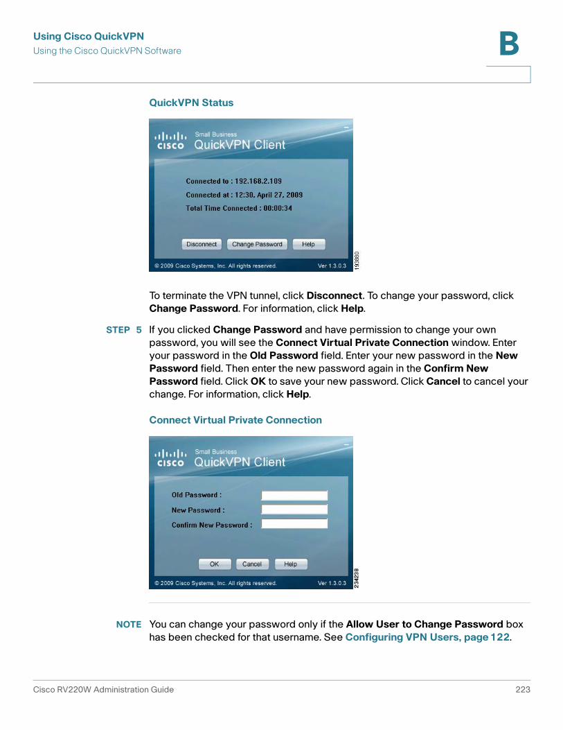
Using Cisco QuickVPN
Using the Cisco QuickVPN Software B
QuickVPN Status
To terminate the VPN tunnel, click Disconnect. To change your password, click
Change Password. For information, click Help.
STEP 5 If you clicked Change Password and have permission to change your own
password, you will see the Connect Virtual Private Connection window. Enter
your password in the Old Password field. Enter your new password in the New
Password field. Then enter the new password again in the Confirm New
Password field. Click OK to save your new password. Click Cancel to cancel your
change. For information, click Help.
Connect Virtual Private Connection
NOTE You can change your password only if the Allow User to Change Password box
has been checked for that username. See Configuring VPN Users, page 122.
Cisco RV220W Administration Guide 223

C
Glossary
Term Definition
beacon interval The time interval at which beacon frames are
transmitted. Beacon frames announce the
existence of the wireless network.
DTIM (Delivery Traffic
Indication Message)
A DTIM field is a countdown field informing
clients of the next window for listening to
broadcast and multicast messages. When the
Cisco RV220W has buffered broadcast or
multicast messages for associated clients, it
sends the next DTIM with a DTIM Interval value.
Its clients hear the beacons and awaken to
receive the broadcast and multicast messages.
dynamic routing Dynamic routing enables the router to adjust
automatically to physical changes in the
network’s layout. Using the dynamic RIP
protocol, the router calculates the most efficient
route for the network’s data packets to travel
between the source and the destination. The
RIP protocol regularly broadcasts routing
information to other routers on the network. It
determines the best route based on the fewest
number of hops between the source and the
destination.
Cisco RV220W Administration Guide 224
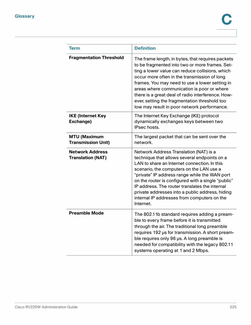
Glossary C
Fragmentation Threshold The frame length, in bytes, that requires packets
to be fragmented into two or more frames. Set-
ting a lower value can reduce collisions, which
occur more often in the transmission of long
frames. You may need to use a lower setting in
areas where communication is poor or where
there is a great deal of radio interference. How-
ever, setting the fragmentation threshold too
low may result in poor network performance.
IKE (Internet Key
Exchange)
The Internet Key Exchange (IKE) protocol
dynamically exchanges keys between two
IPsec hosts.
MTU (Maximum
Transmission Unit)
The largest packet that can be sent over the
network.
Network Address
Translation (NAT)
Network Address Translation (NAT) is a
technique that allows several endpoints on a
LAN to share an Internet connection. In this
scenario, the computers on the LAN use a
“private” IP address range while the WAN port
on the router is configured with a single “public”
IP address. The router translates the internal
private addresses into a public address, hiding
internal IP addresses from computers on the
Internet.
Preamble Mode The 802.11b standard requires adding a pream-
ble to every frame before it is transmitted
through the air. The traditional long preamble
requires 192 μs for transmission. A short pream-
ble requires only 96 μs. A long preamble is
needed for compatibility with the legacy 802.11
systems operating at 1 and 2 Mbps.
Term Definition
Cisco RV220W Administration Guide 225

Glossary C
RADVD (Router
Advertisement Daemon)
RADVD is an open-source software product
that uses the Neighbor Discovery Protocol
(NDP) to listen for router solicitations in the IPv6
LAN. It responds with router advertisements to
support stateless address auto-configuration.
When a new host connects to the network, it
sends a request for its configuration
parameters, and the router responds with a
router advertisement packet that contains the
network-layer configuration parameters
including IPv6 prefixes. The node takes the
prefix and extends it to a full 128 bit address by
adding an EUID based on its hardware address.
Request to Send (RTS)
Threshold
The packet size, in bytes, that requires an RTS/
Clear to Send (CTS) handshake before sending.
A low setting can be useful in areas where many
client devices are associating with the wireless
device, or in areas where the clients are far
apart and can detect only the access point but
not other clients. Although a low threshold value
consumes more bandwidth and reduces the
throughput of the packet, frequent RTS packets
can help the network to recover from
interference or collisions.
Routing Information
Protocol (RIP)
This protocol uses use distance vectors to
mathematically compare routes to identify the
best path to any given destination address. RIP
sends routing-update messages at regular
intervals and when the network topology
changes. Upon receiving a RIP message, a
router updates its routing table and transmits
the updates to other routers. RIP prevents loops
and has features to provide stability despite
potentially rapid changes in a network's
topology.
RIPv2 supports subnet masks, allows more
information to be included in RIP packets, and
provides a simple authentication mechanism
that is not supported by RIP.
Term Definition
Cisco RV220W Administration Guide 226
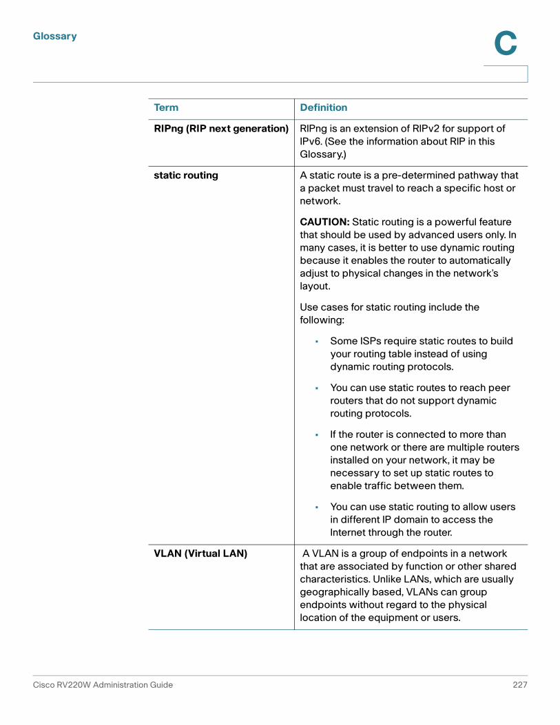
Glossary C
RIPng (RIP next generation) RIPng is an extension of RIPv2 for support of
IPv6. (See the information about RIP in this
Glossary.)
static routing A static route is a pre-determined pathway that
a packet must travel to reach a specific host or
network.
CAUTION: Static routing is a powerful feature
that should be used by advanced users only. In
many cases, it is better to use dynamic routing
because it enables the router to automatically
adjust to physical changes in the network’s
layout.
Use cases for static routing include the
following:
• Some ISPs require static routes to build
your routing table instead of using
dynamic routing protocols.
• You can use static routes to reach peer
routers that do not support dynamic
routing protocols.
• If the router is connected to more than
one network or there are multiple routers
installed on your network, it may be
necessary to set up static routes to
enable traffic between them.
• You can use static routing to allow users
in different IP domain to access the
Internet through the router.
VLAN (Virtual LAN) A VLAN is a group of endpoints in a network
that are associated by function or other shared
characteristics. Unlike LANs, which are usually
geographically based, VLANs can group
endpoints without regard to the physical
location of the equipment or users.
Term Definition
Cisco RV220W Administration Guide 227

D
Cisco RV220W Administration Guide 228
Where to Go From Here
Cisco provides a wide range of resources to help you obtain the full benefits of the
Cisco Small Business RV220W Wireless-N Network Security Firewall.
Support
Cisco Small Business
Support Community
www.cisco.com/go/smallbizsupport
Online Technical Support and
Documentation (Login
Required)
www.cisco.com/support
Cisco Small Business
Support and Resources
www.cisco.com/go/smallbizhelp
Phone Support Contacts www.cisco.com/go/sbsc
Downloads and Documentation
Firmware www.cisco.com/go/software
(Enter the model number to search.)
Open Source Documentation www.cisco.com/en/US/products/ps9923/
prod_release_notes_list.html
(See the RV220W links.)
Cisco RV220W
Documentation
www.cisco.com/go/smallbizrouters
(See the Technical Documentation links.)
Cisco Small Business
Cisco Partner Central for
Small Business (Partner Login
Required)
www.cisco.com/web/partners/sell/smb
Cisco Small Business Home www.cisco.com/smb