Embed Size (px)
Citation preview

Administration Console User Guide
for Cisco Unified Intelligence CenterRelease 8.5(3)
December 2011
Americas Headquarters
Cisco Systems, Inc.
170 West Tasman Drive
San Jose, CA 95134-1706
USA
http://www.cisco.com
Tel: 408 526-4000
800 553-NETS (6387)
Fax: 408 527-0833

THE SPECIFICATIONS AND INFORMATION REGARDING THE PRODUCTS IN THIS MANUAL ARE SUBJECT TO CHANGE WITHOUT NOTICE.ALL STATEMENTS, INFORMATION, AND RECOMMENDATIONS IN THIS MANUAL ARE BELIEVED TO BE ACCURATE BUT ARE PRESENTEDWITHOUT WARRANTY OF ANY KIND, EXPRESS OR IMPLIED. USERS MUST TAKE FULL RESPONSIBILITY FOR THEIR APPLICATION OFANY PRODUCTS.THE SOFTWARE LICENSE AND LIMITED WARRANTY FOR THE ACCOMPANYING PRODUCT ARE SET FORTH IN THE INFORMATION PACKETTHAT SHIPPED WITH THE PRODUCT AND ARE INCORPORATED HEREIN BY THIS REFERENCE. IF YOU ARE UNABLE TO LOCATE THESOFTWARE LICENSE OR LIMITED WARRANTY, CONTACT YOUR CISCO REPRESENTATIVE FOR A COPY.The Cisco implementation of TCP header compression is an adaptation of a program developed by the University of California, Berkeley (UCB) aspart of UCBs public domain version of the UNIX operating system. All rights reserved. Copyright 1981, Regents of the University of California.NOTWITHSTANDING ANY OTHER WARRANTY HEREIN, ALL DOCUMENT FILES AND SOFTWARE OF THESE SUPPLIERS ARE PROVIDED"AS IS" WITH ALL FAULTS. CISCO AND THE ABOVE-NAMED SUPPLIERS DISCLAIM ALL WARRANTIES, EXPRESSED OR IMPLIED, INCLUDING,WITHOUT LIMITATION, THOSE OF MERCHANTABILITY, FITNESS FOR A PARTICULAR PURPOSE AND NONINFRINGEMENT OR ARISINGFROM A COURSE OF DEALING, USAGE, OR TRADE PRACTICE.IN NO EVENT SHALL CISCO OR ITS SUPPLIERS BE LIABLE FOR ANY INDIRECT, SPECIAL, CONSEQUENTIAL, OR INCIDENTAL DAMAGES,INCLUDING, WITHOUT LIMITATION, LOST PROFITS OR LOSS OR DAMAGE TO DATA ARISING OUT OF THE USE OR INABILITY TO USETHIS MANUAL, EVEN IF CISCO OR ITS SUPPLIERS HAVE BEEN ADVISED OF THE POSSIBILITY OF SUCH DAMAGES.Cisco and the Cisco logo are trademarks or registered trademarks of Cisco and/or its affiliates in the U.S. and other countries. To view a list of Ciscotrademarks, go to http://www.cisco.com/go/trademarksCCVP, the Cisco logo, and Welcome to the Human Network are trademarks of Cisco Systems, Inc.; Changing the Way We Work, Live, Play, andLearn is a service mark of Cisco Systems, Inc.; and Access Registrar, Aironet, Catalyst, CCDA, CCDP, CCIE, CCIP, CCNA, CCNP, CCSP, Cisco,the Cisco Certified Internetwork Expert logo, Cisco IOS, Cisco Press, Cisco Systems, Cisco Systems Capital, the Cisco Systems logo, Cisco Unity,Enterprise/Solver, EtherChannel, EtherFast, EtherSwitch, Fast Step, Follow Me Browsing, FormShare, GigaDrive, HomeLink, Internet Quotient, IOS,iPhone, IP/TV, iQ Expertise, the iQ logo, iQ Net Readiness Scorecard, iQuick Study, LightStream, Linksys, MeetingPlace, MGX, Networkers, NetworkingAcademy, Network Registrar, PIX, ProConnect, ScriptShare, SMARTnet, StackWise, The Fastest Way to Increase Your Internet Quotient, andTransPath are registered trademarks of Cisco Systems, Inc. and/or its affiliates in the United States and certain other countries. Any Internet Protocol(IP) addresses used in this document are not intended to be actual addresses. Any examples, command display output, and figures included in thedocument are shown for illustrative purposes only. Any use of actual IP addresses in illustrative content is unintentional and coincidental.Third-party trademarks mentioned are the property of their respective owners. The use of the word partner does not imply a partnership relationshipbetween Cisco and any other company. (1110R)Copyright 2011 Cisco Systems, Inc. All rights reserved.

Table of Contents
Preface ...........................................................................................................................................................1Purpose .....................................................................................................................................................1Audience ....................................................................................................................................................1Organization ..............................................................................................................................................1Related Documentation .............................................................................................................................2Conventions................................................................................................................................................2Obtaining Documentation and Submitting a Service Request...................................................................3Documentation Feedback...........................................................................................................................4
1. The Administration Console........................................................................................................................5About the Administration Console..............................................................................................................5Who can Sign In to Unified IC Administration?...........................................................................................6The Welcome Page....................................................................................................................................6About the Unified IC Cluster.......................................................................................................................7
Nodes in the Unified IC Cluster.............................................................................................................7
2. Admin User Management Drawer...............................................................................................................9Admin Users...............................................................................................................................................9
Multiple Super Users and Security......................................................................................................10Configure User.........................................................................................................................................11
3. Device Management Drawer.....................................................................................................................15Device Configuration................................................................................................................................15
Defining the Member Node in the Administration Console..................................................................17Device Configuration Detail.................................................................................................................18
Log and Trace Settings.............................................................................................................................19About Logging and Tracing..................................................................................................................20Edit Serviceability Settings..................................................................................................................20Infrastructure Trace Definitions............................................................................................................23Subsystem Trace Definitions - OAMPServer.......................................................................................24Subsystem Trace Definitions - CUICServer.........................................................................................25
Changing the IP Address in CUIC............................................................................................................26Readiness Checklist............................................................................................................................27Tasks to be Performed Before Changing the IP Address.....................................................................27Changing the Cluster IP Addresses for Subscriber Servers That Are Defined by IP Addresses.........28Changing the Cluster IP Address for the Publisher Server That Is Defined by IP Address.................30Changing the Cluster IP Addresses for Subscriber Servers That Are Defined by Host Name............31Changing the Cluster IP Addresses for Publisher Servers That Are Defined by Host Name..............34
4. Control Center Drawer..............................................................................................................................37
5. Cluster Configuration Drawer....................................................................................................................39Reporting Configuration...........................................................................................................................39
Active Directory Tab.............................................................................................................................39Configuring Active Directory with SSL.................................................................................................41Report Scheduler Email Settings Tab..................................................................................................41
Unified CCE User Integration Configuration.............................................................................................42About Unified CCE User Integration....................................................................................................44
License File Management........................................................................................................................45
6. Network Management Drawer...................................................................................................................47
Administration Console User Guide for Cisco Unified Intelligence Center Release 8.5(3)
i

SNMP (Simple Network Management Protocol)......................................................................................47Unified IC SNMP MIBs.............................................................................................................................48
MIB Objects.........................................................................................................................................48MIB Notifications (CUIC TRAPs).........................................................................................................53
7. Tools Drawer..............................................................................................................................................57RTMT........................................................................................................................................................57
Download and Launch RTMT..............................................................................................................58RTMT Integration with Unified IC ........................................................................................................59The RTMT Interface.............................................................................................................................61Unified IC Performance Objects and Counters....................................................................................63Unified IC Counters.............................................................................................................................65
8. The Administration Console Interface.......................................................................................................89Drawers....................................................................................................................................................89Filter.........................................................................................................................................................90Online Help...............................................................................................................................................90Sorting......................................................................................................................................................90Title Bar....................................................................................................................................................91Licenses...................................................................................................................................................91
How To Obtain Your License................................................................................................................91License Types......................................................................................................................................92
Users in the Administration Console........................................................................................................93Super Users.........................................................................................................................................93System Application User......................................................................................................................93System Administration User................................................................................................................94
Appendix A. Command Line Interface...........................................................................................................95Using CLI..................................................................................................................................................96Delete Commands....................................................................................................................................98
delete account.....................................................................................................................................98delete dns............................................................................................................................................99delete ipsec..........................................................................................................................................99delete process.....................................................................................................................................99delete smtp..........................................................................................................................................99
File Commands......................................................................................................................................100file check............................................................................................................................................100file delete...........................................................................................................................................100file dump............................................................................................................................................101file get................................................................................................................................................101file list.................................................................................................................................................102file search..........................................................................................................................................102file tail.................................................................................................................................................103file view..............................................................................................................................................103
Run Commands......................................................................................................................................104run loadxml........................................................................................................................................104run sql................................................................................................................................................104
Set Commands.......................................................................................................................................104set account........................................................................................................................................105set accountlocking.............................................................................................................................105set cert...............................................................................................................................................106set cli..................................................................................................................................................106set commandcount............................................................................................................................106
Administration Console User Guide for Cisco Unified Intelligence Center Release 8.5(3)
ii

set cuic-properties.............................................................................................................................107set ipsec.............................................................................................................................................108set logging.........................................................................................................................................109set network .......................................................................................................................................109set password......................................................................................................................................113set smtp.............................................................................................................................................115set syslog...........................................................................................................................................115set timezone......................................................................................................................................115set trace.............................................................................................................................................115set web-security.................................................................................................................................117set workingdir.....................................................................................................................................117
Show Commands...................................................................................................................................117show account.....................................................................................................................................118show accountlocking..........................................................................................................................119show cert...........................................................................................................................................119show cli..............................................................................................................................................119show cuic-properties..........................................................................................................................119show cuis-component-status ............................................................................................................120show cuis-license-info........................................................................................................................120show diskusage.................................................................................................................................121show environment..............................................................................................................................121show hardware...................................................................................................................................121show ipsec.........................................................................................................................................122show logins........................................................................................................................................122show memory....................................................................................................................................122show myself.......................................................................................................................................122show network.....................................................................................................................................123show open.........................................................................................................................................124show packages..................................................................................................................................125show password..................................................................................................................................126show perf...........................................................................................................................................126show process.....................................................................................................................................128show registry......................................................................................................................................130show smtp..........................................................................................................................................130show stats io......................................................................................................................................130show status........................................................................................................................................130show subsys......................................................................................................................................131show tech...........................................................................................................................................131show timezone...................................................................................................................................136show trace.........................................................................................................................................136show ups status.................................................................................................................................137show version......................................................................................................................................137show web-security.............................................................................................................................137show workingdir.................................................................................................................................137
Unset Command.....................................................................................................................................137unset cuic-properties.........................................................................................................................138unset ipsec.........................................................................................................................................138unset network dns..............................................................................................................................138unset_host-to-ip.................................................................................................................................138
Utils Commands.....................................................................................................................................139utils auditd..........................................................................................................................................139
Administration Console User Guide for Cisco Unified Intelligence Center Release 8.5(3)
iii

utils core............................................................................................................................................140utils create report...............................................................................................................................140utils csa..............................................................................................................................................140utils dbreplication...............................................................................................................................141utils diagnose.....................................................................................................................................143utils disaster_recovery.......................................................................................................................143utils firewall........................................................................................................................................145utils iostat ..........................................................................................................................................146utils iothrottle......................................................................................................................................146utils netdump.....................................................................................................................................146utils network.......................................................................................................................................147utils ntp..............................................................................................................................................149utils purge..........................................................................................................................................149utils raid.............................................................................................................................................150utils remote_account..........................................................................................................................150utils_reset..........................................................................................................................................150utils service........................................................................................................................................151utils snmp...........................................................................................................................................152utils soap realtimeservice test...........................................................................................................153utils system........................................................................................................................................153
Appendix B. Load Balancing.......................................................................................................................155Example of ACE Load Balancing Configuration.....................................................................................155
Index ...........................................................................................................................................................159
Administration Console User Guide for Cisco Unified Intelligence Center Release 8.5(3)
iv

List of Figures
Figure 1: Configure User.................................................................................................................................................11
Figure 2: Device Configuration.......................................................................................................................................17
Figure 3: Member Configured.........................................................................................................................................18
Figure 4: Log and Trace Settings.....................................................................................................................................19
Figure 5: ..........................................................................................................................................................................21
Figure 6: SubSystem Settings..........................................................................................................................................22
Figure 7: Select Detailed to edit Trace Definitions.........................................................................................................23
Figure 8: RTMT Desktop Icon........................................................................................................................................58
Figure 9: RTMTTraceLog...............................................................................................................................................59
Figure 10: RTMT Critical Services.................................................................................................................................60
Figure 11: RTMT Alerts..................................................................................................................................................60
Figure 12: RTMT Performance Interface........................................................................................................................61
Figure 13: Report Execution............................................................................................................................................64
Figure 14: RTMT Counter Help......................................................................................................................................65
Figure 15: Drawers in the Administration Console.........................................................................................................89
Figure 16: Online Help Navigation Icon ........................................................................................................................90
Figure 17: Online Help....................................................................................................................................................90
Figure 18: Using ACE....................................................................................................................................................156
Administration Console User Guide for Cisco Unified Intelligence Center Release 8.5(3)
v

Administration Console User Guide for Cisco Unified Intelligence Center Release 8.5(3)
vi

Preface
Purpose
This document explains the Cisco Unified Intelligence Center Administration console.
The Administration console, available an all deployments, is a web-based, centralized interfacefor setting and displaying configuration information about the cluster.
The Administration application is one of two web interfaces for Unified IC. The other is theUnified IC Reporting application.
Audience
This guide is prepared for "Super Users (page 93)" who sign in to the Administration interfaceto administer, provision, monitor, and troubleshoot Cisco Unified Intelligence Center.
Organization
In addition to this Preface, this guide is organized as follows:
DescriptionChapter
Explains the Administration console and the Unified ICcluster.
Chapter 1 (page 5)
Explain the six drawers on the left panel of theAdministration Console page:
Chapters 2 through 7
• Admin User Management (page 9)
Administration Console User Guide for Cisco Unified Intelligence Center Release 8.5(3)
1

DescriptionChapter
• Device Management (page 15)
• Control Center (page 37)
• Cluster Configuration (page 42) (Reporting, UnifiedCCE User Integration, and License File Management)
• Network Management (page 47) (SNMP and MIBs)
• Tools (page 57) (RTMT)
Explains the Cisco System Applications you can openfrom the Navigation menu:
Chapter 8 (page ?)
• Cisco Unified Serviceability (page ?)
• Cisco Unified OS Administration (page ?)
• Disaster Recovery System (page ?)
Explains the Administration Console interface.Chapter 9 (page 89)
Documents the Command Line Interface.Appendix A (page 95)
Note: You cannot access the CLI directly from theAdministration interface.
Includes a configuration example for Load BalancingAppendix B (page 155)
Related Documentation
Guides for the Cisco Unified Intelligence Center (http://www.cisco.com/en/US/products/ps9755/products_user_guide_list.html)
The Bill of Materials for the Cisco Unified Intelligence Center (http://www.cisco.com/en/US/products/ps9755/products_user_guide_list.html)
Troubleshooting tips for the Cisco Unified Intelligence Center (http://docwiki.cisco.com/wiki/Troubleshooting_Unified_Intelligence_Suite)
The Developers' Forum for the Cisco Unified Intelligence Center (http://developer.cisco.com/web/ccr)
Conventions
This manual uses the following conventions:
Administration Console User Guide for Cisco Unified Intelligence Center Release 8.5(3)
2
Preface
Related Documentation

DescriptionConvention
Boldface font is used to indicate commands, such as user entries,keys, buttons, and folder and submenu names. For example:
boldface font
• Choose Edit > Find.
• Click Finish.
Italic font is used to indicate the following:italic font
• To introduce a new term. Example: A skill group is acollection of agents who share similar skills.
• For emphasis. Example: Do not use the numerical namingconvention.
• A syntax value that the user must replace. Example: IF(condition, true-value, false-value)
• A book title. Example: See the Cisco CRS Installation Guide.
Window font, such as Courier, is used for the following:window font
• Text as it appears in code or that the window displays.Example: <html><title>Cisco Systems,Inc. </title></html>
Angle brackets are used to indicate the following:< >
• For arguments where the context does not allow italic, suchas ASCII output.
• A character string that the user enters but that does not appearon the window such as a password.
Obtaining Documentation and Submitting a Service Request
For information on obtaining documentation, submitting a service request, and gatheringadditional information, see the monthly What's New in Cisco Product Documentation, whichalso lists all new and revised Cisco technical documentation, at:
http://www.cisco.com/en/US/docs/general/whatsnew/whatsnew.html
Subscribe to the What's New in Cisco Product Documentation as a Really Simple Syndication(RSS) feed and set content to be delivered directly to your desktop using a reader application.The RSS feeds are a free service and Cisco currently supports RSS version 2.0.
Administration Console User Guide for Cisco Unified Intelligence Center Release 8.5(3)
3
Preface
Obtaining Documentation and Submitting a Service Request

Documentation Feedback
You can provide comments about this document by sending email to the following address:
mailto:[email protected]
We appreciate your comments.
Administration Console User Guide for Cisco Unified Intelligence Center Release 8.5(3)
4
Preface
Documentation Feedback

The Administration ConsoleThis chapter contains the following topics:
• About the Administration Console, page 5• Who can Sign In to Unified IC Administration?, page 6• The Welcome Page, page 6• About the Unified IC Cluster, page 7
About the Administration Console
Unified IC is installed on a Cisco Unified Operating System platform as a cluster with a maximumof eight nodes: one Controller node and up to seven Member nodes.
The Controller node is mandatory and provides both the Administration and the Unified ICReporting web applications. As cluster can consist of the Controller node only.
Member nodes are optional and have the Unified IC Reporting application only. (Unified ICAdministration is not available on a Member node.)
The Administration console manages all components in a Unified deployment and also provideslinks to:
• Cisco Unified Serviceability (page ?) and SNMP (page 47)
• Cisco Unified OS Administration (page ?)
• Disaster Recovery System (page ?)
• Real Time Monitoring Tool (RTMT) (page 57)
Administration Console User Guide for Cisco Unified Intelligence Center Release 8.5(3)
5
Chapter 1

Who can Sign In to Unified IC Administration?
The System Application User (page 93) who is defined during the Installation is by default theinitial Super User who can sign in to the Administration Application.
This initial Super User can then create other Super Users in the Admin Users (page 9) page.
To access the Administration console:
1. Direct your browser to the URL https://<HOST ADDRESS>/oamp where HOST ADDRESSis the IP Address or Hostname of your server.
2. Sign in, using your Super User (system application user) ID and password.
A successful sign in launches the Welcome Page (page 6).
The session timeout for inactivity is thirty minutes. It is not configurable.
See also: Users in the Administration Console (page 93).
The Welcome Page
The Welcome page appears by default after a successful sign in.
The left panel of the Welcome page contains drawers (page 89).
Drawers are similar to menus in that they group logically-related functional elements. Clickinga drawer in the left panel opens a panel on the right where you can define or display parametersfor a function.
Table 1: Actions from this page
Do thisTo
Click a drawer in the left panel.Display the values for a function.
Click the Cisco logo at the top left.Open the cisco.com website.
Options are:Select from the Navigation dropdownat the top right.
• Cisco Unified Serviceability (page ?)
Use to view and configure operating systemserviceability parameters (such as Alarm, Trace,and SNMP).
• Cisco Unified OS Administration (page ?)
Administration Console User Guide for Cisco Unified Intelligence Center Release 8.5(3)
6
Chapter 1: The Administration Console
Who can Sign In to Unified IC Administration?
Do thisTo
Use to configure and manage operating systemparameters (such as IP settings and remote supportaccounts).
• Disaster Recovery System (page ?)
Use to manage backup and restore procedures.
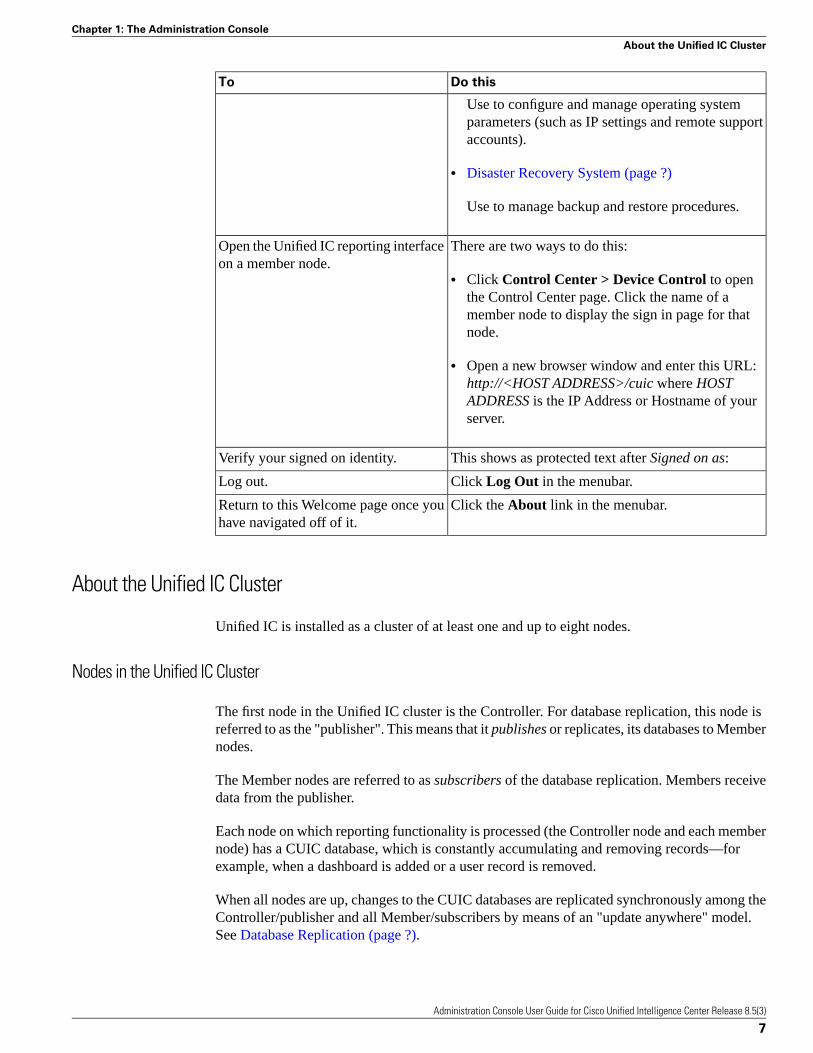
There are two ways to do this:Open the Unified IC reporting interfaceon a member node.
• Click Control Center > Device Control to openthe Control Center page. Click the name of amember node to display the sign in page for thatnode.
• Open a new browser window and enter this URL:http://<HOST ADDRESS>/cuic where HOSTADDRESS is the IP Address or Hostname of yourserver.
This shows as protected text after Signed on as:Verify your signed on identity.
Click Log Out in the menubar.Log out.
Click the About link in the menubar.Return to this Welcome page once youhave navigated off of it.
About the Unified IC Cluster
Unified IC is installed as a cluster of at least one and up to eight nodes.
Nodes in the Unified IC Cluster
The first node in the Unified IC cluster is the Controller. For database replication, this node isreferred to as the "publisher". This means that it publishes or replicates, its databases to Membernodes.
The Member nodes are referred to as subscribers of the database replication. Members receivedata from the publisher.
Each node on which reporting functionality is processed (the Controller node and each membernode) has a CUIC database, which is constantly accumulating and removing records—forexample, when a dashboard is added or a user record is removed.
When all nodes are up, changes to the CUIC databases are replicated synchronously among theController/publisher and all Member/subscribers by means of an "update anywhere" model.See Database Replication (page ?).
Administration Console User Guide for Cisco Unified Intelligence Center Release 8.5(3)
7
Chapter 1: The Administration Console
About the Unified IC Cluster

Database maintenance is performed by the Disaster Recovery System (page ?).
Administration Console User Guide for Cisco Unified Intelligence Center Release 8.5(3)
8
Chapter 1: The Administration Console
About the Unified IC Cluster

Admin User Management DrawerSelect Admin User Management drawer > Admin User Management to access the AdminUser Management page, where you view and maintain the Super Users for the Administrationconsole.
Super Users are authorized to add and maintain the functions that are controlled in theAdministration console, such as adding devices and starting or stopping services.
Note: Super Users can also sign in to Unified IC Reporting.
This chapter contains the following topics:
• Admin Users, page 9• Configure User, page 11
Admin Users
The Admin Users page is a list of the names and roles for all configured Super Users in thesystem. This list always contains at least one row that shows the System Application User whois configured during installation and who becomes the initial Super User for Unified IC. SeeUsers in the Administration Console (page 93).
To navigate to this page, click the Admin User Management drawer > Admin UserManagement.
The rows on the Users page contain two columns. There is a checkbox to the left of each rowfor selecting that user. Click the checkbox in the heading row to select all users. Use the Filter(page 90) feature narrow the list of names.
Administration Console User Guide for Cisco Unified Intelligence Center Release 8.5(3)
9
Chapter 2
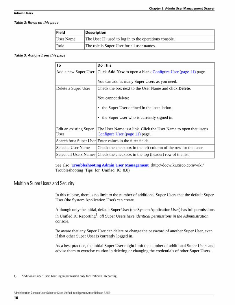
Table 2: Rows on this page
DescriptionField
The User ID used to log in to the operations console.User Name
The role is Super User for all user names.Role
Table 3: Actions from this page
Do ThisTo
Click Add New to open a blank Configure User (page 11) page.Add a new Super User
You can add as many Super Users as you need.
Check the box next to the User Name and click Delete.Delete a Super User
You cannot delete:
• the Super User defined in the installation.
• the Super User who is currently signed in.
The User Name is a link. Click the User Name to open that user'sConfigure User (page 11) page.
Edit an existing SuperUser
Enter values in the filter fields.Search for a Super User
Check the checkbox in the left column of the row for that user.Select a User Name
Check the checkbox in the top (header) row of the list.Select all Users Names
See also: Troubleshooting Admin User Management (http://docwiki.cisco.com/wiki/Troubleshooting_Tips_for_Unified_IC_8.0)
Multiple Super Users and Security
In this release, there is no limit to the number of additional Super Users that the default SuperUser (the System Application User) can create.
Although only the initial, default Super User (the System Application User) has full permissions
in Unified IC Reporting1, all Super Users have identical permissions in the Administrationconsole.
Be aware that any Super User can delete or change the password of another Super User, evenif that other Super User is currently logged in.
As a best practice, the initial Super User might limit the number of additional Super Users andadvise them to exercise caution in deleting or changing the credentials of other Super Users.
1) Additional Super Users have log in permission only for Unified IC Reporting.
Administration Console User Guide for Cisco Unified Intelligence Center Release 8.5(3)
10
Chapter 2: Admin User Management Drawer
Admin Users

Configure User
Use this page to create configuration data for a new Super User or to edit the configuration datafor an existing Super User.
To navigate to this page, click Admin User Management drawer > Admin User Managementto open the Users page. Then click Add New to add and configure a new user or click an existingUser Name to edit the configuration for that user.
This page has three tabs - General, Credentials, and Policy.
Figure 1: Configure User
If a field is grayed-out, then that field it not editable. An asterisk indicates that the field isrequired.
Actions on this page are Save and Cancel.
Table 4: General Tab
DescriptionField
The user Id for the user.User Name
Password.Password
To require a secure password, enable Check for Trivial Passwords onthe Policy tab.
The same password as above to confirm spelling.Confirm Password
The only role is Super User.Role
The values on the General tab apply to the specific Super User being added or edited.
Administration Console User Guide for Cisco Unified Intelligence Center Release 8.5(3)
11
Chapter 2: Admin User Management Drawer
Configure User

Table 5: Credentials Tab
DescriptionField
If checked, this Super User is locked out.Locked byAdministrator
This pertains to the user password. Select eitherUser Cannot Changeor User Must Change at Next Login. You cannot select both.
User CannotChange/Must Change
This pertains to the user password.Does Not Expire
If the Credentials Expire After (days) field on the Policy tab is checked,then this field is disabled.
If the Credentials Expire After (days) field on the Policy tab is clear,check Does Not Expire to enable a persistent password for the SuperUser.
Note: DO NOT check the Does Not Expire box if you have checkedUser Must Change at Next Login, as the user will not be prompted tochange the password at the next login.
Check this box to reset the hack count for this user and clear the TimeLocked Due to Failed Login Attempts field. After the counter resets,the user can try logging in again.
Reset Hack Count
Note: If the user is locked out of the account due to failed loginsexceeding the number set for Failed Login (on the policy tab), thenyou can unlock the account by checking this box and clicking Save.
Displays the number of failed logon attempts since the last successfullogon, since the hack count was reset for this Super User credential, orsince the reset failed login attempts time has expired.
Failed Login Attempts
Displays the last time this user's credentials were changed.Time Last Changed
Displays the date and time of the last login attempt by the user.Time of Last FailedLogin Attempt
Displays the date and time that this user account was locked.Time Locked byAdministrator
Displays the date and time that the system last locked this user accountdue to failed logon attempts.
Time Locked Due toFailed LogonAttempts
The values on the Credentials tab apply to the specific Super User being added or edited.
Note: The credentials for Administration Super Users are encrypted into the local database.Super Users are not authenticated through Active Directory.
Administration Console User Guide for Cisco Unified Intelligence Center Release 8.5(3)
12
Chapter 2: Admin User Management Drawer
Configure User

Table 6: Policy Tab
DescriptionField
Specify the number of allowed failed logon attempts. Whenthis threshold is reached, the system locks the account.
Failed Logon
Allowed range is 0 to 10. To allow unlimited logon attempts,enter a value of 0 or check the No Limit for Failed Logonsbox.
Specify the number of minutes before the counter is reset forfailed logon attempts. After the counter resets, the user cantry logging in again. Allowed range is 0 to 120; default is 30.
Reset Failed Logon Attemptsevery (minutes)
Specify the number of minutes an account remains lockedwhen the number of failed logon attempts exceeds the
Locked Duration (minutes)
specified threshold. Allowed range is 0 to 120; default is 30.Checking the Administrator Must Unlock check box meansthat the account must be unlocked manually.
Specify the number of minutes that are required before a usercan change credentials again. Allowed range is 0 to 120;default is 0.
Minimum Duration BetweenCredential Changes (minutes)
Enter an integer here to define in how many days this user'scredentials shall expire. After this many days has elapsed,
Credentials Expire After (days)
the user will no longer be able to login. Optionally you cancheck Never Expires to have the credentials never expire.
Minimum number of characters for the password.Minimum Credential Length
Specify the number of previous passwords that the systemstores. The system does not allow changing the password if
Stored Number of PreviousCredentials
the new password matches with any of the stored passwords.The maximum permissible value for this field is 15; thedefault value is 5, indicating that the new password shouldnot be the same as the last 5 passwords.
Specify the number of days that a password can remaininactive before the account gets locked. Allowed range is 0to 5000; default is 0.
Inactive Days Allowed
Specify the number of days before a user password expiresto start warning notifications. Allowed range is 0 to 90;default is 0.
Expiry Warning Days
Check this check box to require the system to disallowcredentials that are easily hacked, such as common words,repeated character patterns, and so on.
Check for Trivial Passwords
The values on the Policy tab apply to all Super Users.
Administration Console User Guide for Cisco Unified Intelligence Center Release 8.5(3)
13
Chapter 2: Admin User Management Drawer
Configure User

Administration Console User Guide for Cisco Unified Intelligence Center Release 8.5(3)
14
Chapter 2: Admin User Management Drawer
Configure User

Device Management DrawerOpen the Device Management drawer to view and maintain the devices in the cluster and toview log and trace settings for those devices.
Devices are the physical machines servers on which the Cisco Unified Intelligence CenterAdministration Console and the Cisco Unified Intelligence Center reporting application areinstalled.
See also: Troubleshooting Device Management (http://docwiki.cisco.com/wiki/Troubleshooting_Tips_for_Unified_IC_8.0)
This chapter contains the following topics:
• Device Configuration, page 15• Log and Trace Settings, page 19• Changing the IP Address in CUIC, page 26
Device Configuration
This pages lists all currently-configured devices (nodes) in the cluster that contain the UnifiedIC reporting process.
A cluster can contain a maximum of eight such devices: one Controller (which runs bothAdministration and Unified IC reporting) and seven Members (which run Unified IC).
Note:
• The license type determines the number of devices (nodes) that you can install and configure.See License Types (page 92).
• You cannot add a member node until you have uploaded the license.
To navigate to this page, click Device Management > Device Configuration.
Administration Console User Guide for Cisco Unified Intelligence Center Release 8.5(3)
15
Chapter 3

This list always contains at least one row for the Controller, which is added by the installation.You cannot delete the Controller from this page. To delete the Controller, you must uninstallit.
Note: Before you can install a new Member node, you must define the Member in this interface.
The rows on the Device Summary page contain four columns. There is a checkbox to the leftof each row for selecting that device for deletion. Click the checkbox in the heading row toselect all devices.
Table 7: Rows on this page
DescriptionField
The name of the device is a link. Click a name to edit the configuration forthat device.
Name
The software assigns default alias names - for the Controller, CUIC1; for themembers, Member1, Member2, and so forth.
You can edit the default aliases to names that are more meaningful for you.
The IP address for the device.Host Address
A description of the device.Description
The type of device: Controller or Member.Type
• There is one Controller. It runs both the Administration console and UnifiedIC Reporting.
• There can be a maximum of seven Members. Members run the Unified ICReporting.
Table 8: Actions from this page
Do ThisTo
Click Add Member to open a blank Device Configuration Detail(page 18) page for a new member. This button is disabled if you have
Add Member
not applied a license or when you have the maximum number ofmembers allowed by your license.
Check the box at the left of the device row and click Delete.Delete a device
You cannot delete the Controller.
The interface allows you to delete Members, but you must reinstall aMember device to add it back to the cluster.
Each device name is a link. Click the name link to open its DeviceConfiguration Detail (page 18) page.
Edit an existing device
Administration Console User Guide for Cisco Unified Intelligence Center Release 8.5(3)
16
Chapter 3: Device Management Drawer
Device Configuration

Defining the Member Node in the Administration Console
If you intend to add a Member node, you must define the Member in the Administration consolebefore you run the installation for the member.
Step 1 To access the Administration console, direct a browser to the URL http://<HOST ADDRESS>/oamp where HOST ADDRESS is the IP Address or Hostname of your server.
Step 2 Sign in using the system application user ID and password that you defined during installation.
Step 3 From the panel in the left, select the Device Management drawer. Then select DeviceConfiguration.
Figure 2: Device Configuration
The Device Configuration page shows the Controller that you have installed. Note that thehostname defaults to the alias CUIC1. (You can change it.)
Step 4 On the Device Configuration page, click Add Member.
Step 5 On the Device Configuration fields for the new member, enter a name by which you can identifythe member, the hostname or IP address, and a description for the device.
Step 6 Click Save.
The Member appears on the Device Configuration list.
Administration Console User Guide for Cisco Unified Intelligence Center Release 8.5(3)
17
Chapter 3: Device Management Drawer
Device Configuration

Figure 3: Member Configured
Now that the Member is defined in Device Configuration, you can begin to configure and installas documented in the Installation Guide for Cisco Unified Intelligence Center.
Device Configuration Detail
Use the device configuration detail page to define information about a new device or to editinformation about an existing device.
To navigate to this page, click Device Management > Device Configuration. Then click AddController or Add Member to add and configure a new device or click an existing device nameto edit the detail configuration for that device
Text at the top of the page shows the type of server you are adding or editing.
Table 9: Rows on this page
DescriptionField
The name of the device. (Required)Name
The IP address or hostname of the device. (Required)Host Address
You cannot edit the IP address of the Controller on this page.
Note: There is a CLI command to change the IP address of the Controller,but that command is unsupported for Unified IC.
You can edit the IP address of a Member on this page, but changing it heredoes not effect a change in the cluster. The cluster continues to recognizethe original IP address for replication, and the replication will fail.
Note: There is a CLI command to change the IP address of the Member, butthat command is unsupported for Unified IC. The only way to change theIP address of a member node is to reinstall the member node.
Administration Console User Guide for Cisco Unified Intelligence Center Release 8.5(3)
18
Chapter 3: Device Management Drawer
Device Configuration

DescriptionField
The description of the deviceDescription
Actions on this page are Save (changes), Cancel (changes), and Refresh (page).
Log and Trace Settings
Use the Log and Trace Settings page to see the list of Host Addresses for all configured devicesand to configure log and trace settings for those devices.
This page is accessed from Device Management > Logging and Tracing.
Click the arrow icon at the left of each host address to expand the row and display the list ofserver processes running on that device. The server processes are identified by name, and eachname is a link.
Figure 4: Log and Trace Settings
The host address for the Controller expands to show two processes - OAMPServer and the namefor the Unified IC reporting server processes running on the Controller. These names are links.
The logs in the current version of CUIC server will be removed while upgrading it to CUIC8.5(3)release. This is to avoid the growth of the disk space in CUIC server.
For example, when you upgrade CUIC server from CUIC 8.0(x) to CUIC 8.5(3), all the logs inthe inactive partition i.e., CUIC 8.0(x) would have been removed after the upgrade. So it isadvisable to take a backup of all the logs in the current CUIC version (if they are needed) to adifferent location before upgrading the CUIC server to CUIC 8.5(3) release.
The logs present in the current CUIC version can be downloaded using RTMT tool beforestarting the CUIC upgrade to version 8.5(3).
The logs under the following directories are impacted :
1. /var/log/active/cm
2. /var/log/active/cuic
Click the link to open the Edit Serviceability Settings (page 20) page for that server process.
Administration Console User Guide for Cisco Unified Intelligence Center Release 8.5(3)
19
Chapter 3: Device Management Drawer
Log and Trace Settings

See also: Troubleshooting Log and Trace Settings (http://docwiki.cisco.com/wiki/Troubleshooting_Tips_for_Unified_IC_8.0).
About Logging and Tracing
Logging and Tracing are two mechanisms for application monitoring and management and aredifferentiated as follows:
• Logs contain predefined, higher-level messages that can indicate everything from normalsystem behavior to severe error conditions.
• Traces are free-form, developer-oriented, detailed information that is not printed to the logsby default, but only when increased logging is enabled to debug problems.
You configure log levels to be basic or detailed. Basic is the default. When you change the loglevels to detailed, you have the opportunity to select specific trace level definitions.
There are two ways to review log and tracing information:
• The Command Line Interface (page 95). Using the show trace command.
• The RTMT (page 57)
Edit Serviceability Settings
This page opens when you click the link for the OAMPServer or CUIC server process on theLog and Trace Settings (page 19) page.
Use the Edit Serviceability Settings page to provide syslog server connection settings and tochange the type of logging the servers provide.
Administration Console User Guide for Cisco Unified Intelligence Center Release 8.5(3)
20
Chapter 3: Device Management Drawer
Log and Trace Settings

Figure 5:
Caution: Modify the settings on this page only under the direction of, and with the assistanceof, your support provider.
Log Settings
Use these required fields to define the maximum size of the log directory and of each log file.
Table 10: Log setting rows
DescriptionField
Enter a numeric value between 50 and 50,000. The default is1,500.
Maximum Log Directory Size
Enter a numeric value between 1 and 50. The default is 50.Maximum Log File Size
When the directory size exceeds 50,000, the oldest log files are deleted.
When a log size exceeds 50, a new log file is created.
Syslog Settings
Use these fields to identify the server where the log files are stored.
Administration Console User Guide for Cisco Unified Intelligence Center Release 8.5(3)
21
Chapter 3: Device Management Drawer
Log and Trace Settings

Table 11: Log file storage rows
DescriptionField
The host address of the primary syslog server that stores thelog files.
Primary Host
Note: The port is fixed at 514.
The host address of the backup syslog server that stores thelog files.
Backup Host
Note: The port is fixed at 514.
Subsystem Settings
Navigate in this expandable list of subsystems to set the log levels and trace definitions (page22) for each subsystem.
Figure 6: SubSystem Settings
Actions on this page
• Save - Saves the changes you have made.
• Cancel - Undoes all changes you have made since the last save.
• Refresh - Undoes all changes and revert fields back to the default values.
• Reset - restores the original settings and does not keep your changes.
See also: Log Levels and Trace Level Definitions: Basic and Detailed (page 22)
Log Levels and Trace Level Definitions: Basic and Detailed
There are two log levels for all subsystems:
Basic
This is the default log level. With this setting, messages and warnings are displayed (INFO,ERROR, and WARN).
When the log level is basic, the trace definitions are not editable.
Detailed
Administration Console User Guide for Cisco Unified Intelligence Center Release 8.5(3)
22
Chapter 3: Device Management Drawer
Log and Trace Settings

If you check the detailed log level, the trace check boxes for Subsystem Specific Trace Definitionsand Infrastructure Trace Definitions become editable. You can check the boxes to turn on specifictrace code paths to output to the log file.
Figure 7: Select Detailed to edit Trace Definitions
Trace Definitions are documented in the Administration Console User Guide for Cisco UnifiedIntelligence Center. They are not documented in the Online help.
There are two ways to review log and trace information:
• The Command Line Interface (show trace).
• RTMT (page 57)
Infrastructure Trace Definitions
Infrastructure Trace Definitions are the same for CUIC and for Operation AdministrationMaintenance and Provisioning (OAMP) Infrastructure and OAMP-BO. There are no InfrastructureTrace Definitions for OAMP WSM_BO.
DescriptionTrace
Description of the exception and how it washandled
TRACE_HANDLED_EXCEPTION
JMX and management interface related traces.TRACE_JMX
JMS and message bus related traces.TRACE_JMS
Related to heartbeats, heartbeat thread, orheartbeat send/received
TRACE_HEARTBEAT
For any parameters (not just method arguments)TRACE_PARAM
For traces related to a call / call processingTRACE_CALL
For general debug details of incoming/outgoingmessages
TRACE_MESSAGE
Trace for notification APITRACE_NOTIFICATION
General traces for config APITRACE_GENERAL_CFG
Set this bit to enable OoOQueue tracingTRACE_OOOQUEUE
When entering/exiting a methodTRACE_METHOD
Bits and Bytes, etcTRACE_LOW_LEVEL
Administration Console User Guide for Cisco Unified Intelligence Center Release 8.5(3)
23
Chapter 3: Device Management Drawer
Log and Trace Settings

Subsystem Trace Definitions - OAMPServer
OAMP
Operation Administration Maintenance and Provisioning (OAMP) Subsystem SpecificTrace Definitions
DefinitionTrace
To control logging for looping/bulk operationsTRACE_BULK
For tracing the general OAMP UITRACE_GENERAL_UI
For tracing ExceptionsTRACE_EXCEPTION
For tracing ParametersTRACE_PARAM
Trace DB Access for db fetch and modify suchas Save, Update, Delete
TRACE_DBACCESS
For tracing of Entry/Exit of MethodsTRACE_METHOD
Infrastructure
Infrastructure Subsystem Specific Trace Definitions
DescriptionTrace
Operations of the Stats ManagerTRACE_STATS
Traces to do serviceability, the act of loggingand tracing
TRACE_SERVICEABILITY
All Infrastructure thread operationsTRACE_THREAD
TRACE_SNMP SNMP Forwarder/logging/statsTRACE_SNMP
Log detailed shutdown infoTRACE_SHUTDOWN
Log any/all licensing operationsTRACE_LICENSING
Log detailed startup infoTRACE_STARTUP
When loading subsystemsLOAD_SUBSYSTEM
Logs when a Timer expiresTRACE_TIMER
OAMP-BO
OAMP-BO Subsystem Specific Trace Definitions
DescriptionTrace
To control logging for looping/bulk operationsTRACE_BULK
For tracing ExceptionsTRACE_EXCEPTION
General Traces for OAMP back-endTRACE_GENERAL_BO
Administration Console User Guide for Cisco Unified Intelligence Center Release 8.5(3)
24
Chapter 3: Device Management Drawer
Log and Trace Settings

DescriptionTrace
For tracing ParametersTRACE_PARAM
Trace DB Access for db fetch and modify suchas Save, Update, Delete
TRACE_DBACCESS
For tracing of Entry/Exit of MethodsTRACE_METHOD
WSM-BO
WSM-BO Subsystem Specific Trace Definitions
DescriptionTrace
For tracing ExceptionsTRACE_EXCEPTION
General Traces for OAMP back-endTRACE_GENERAL_BO
For tracing ParametersTRACE_PARAM
Trace DB Access for db fetch and modify suchas Save, Update, Delete
TRACE_DBACCESS
For tracing of Entry/Exit of MethodsTRACE_METHOD
Subsystem Trace Definitions - CUICServer
CUIC
CUIC Subsystem Specific Trace Definitions
CUIC Subsystem, Cache, Thread, Schedule, Util, Statistics, JMX, I18N, L10N, Message, Help
DefinitionTrace
Trace for CuicSubsystem setupCUIC_SUBSYS_SETUP
Trace for CuicSubsystem object dumpCUIC_SUBSYS_OBJECT
Infrastructure
Infrastructure Subsystem Specific Trace Definitions
DescriptionTrace
Operations of the Stats ManagerTRACE_STATS
Traces to do serviceability, the act of loggingand tracing
TRACE_SERVICEABILITY
All Infrastructure thread operationsTRACE_THREAD
TRACE_SNMP SNMP Forwarder/logging/statsTRACE_SNMP
Log detailed shutdown infoTRACE_SHUTDOWN
Log any/all licensing operationsTRACE_LICENSING
Administration Console User Guide for Cisco Unified Intelligence Center Release 8.5(3)
25
Chapter 3: Device Management Drawer
Log and Trace Settings

DescriptionTrace
Log detailed startup infoTRACE_STARTUP
When loading subsystemsLOAD_SUBSYSTEM
Logs when a Timer expiresTRACE_TIMER
CUIC MODEL OBJECTS
CUIC Model Objects Specific Trace Definitions for Reports, ReportDefinitions, Templates,Dashboards, Categories, Value Lists, Collections
DescriptionTrace
Trace dashboard objectsMODEL_DASHBOARD
Trace data source objectsMODEL_DATA_SOURCE
Trace report definition objectsMODEL_REPORT_DEFINITION
Trace collection objectsMODEL_COLLECTION
Trace report objectsMODEL_REPORT
Trace value list objectsMODEL_VALUE_LIST
CUIC DATA PROCESSING
CUIC Data Processing Subsystem Specific Trace Definitions for DataSource, DataProcessing,Hibernate
DescriptionTrace
Trace for DCP other than worker threadsDCP
Trace for DCP worker threadsDCP_WORKER
CUIC SECURITY
CUIC Data Processing Subsystem Specific Trace Definitions for Encryption, Permission,User, Group, ICM User Synchronization
DescriptionTrace
Trace for security operation detailsPERMISSION_OPERATION
Trace for security object detailsPERMISSION_OBJECT
Changing the IP Address in CUIC
Warning: Perform the IP Address change only during a maintenance window.
Administration Console User Guide for Cisco Unified Intelligence Center Release 8.5(3)
26
Chapter 3: Device Management Drawer
Changing the IP Address in CUIC

You can now change the IP address of a Cisco Unified Intelligence Center nodes. You maywant to change this IP address for a variety of reasons, including moving the server from onesegment to another or resolving a duplicate IP address problem.
Readiness Checklist
Perform the following tasks to ensure that your system is prepared for a successful IP addresschange.
If you have a DNS configured anywhere on the CUIC servers, ensure the following beforechanging the IP address:
• There is a forward and reverse lookup zone configured.
• The DNS is reachable and working.
Note: If you do not receive the results that you expect when you perform these tasks, do notcontinue with this procedure until after you resolve any problems that you find.
Tasks to be Performed Before Changing the IP Address
Step 1 List all servers in the cluster and note whether the nodes are defined by using IP addresses orhost names.
a. From the OAMP on the first node, navigate to Device Configuration > DeviceManagement. System dislpays a list of all servers in the cluster.
b. Capture this list of servers for later reference.
Step 2 Ensure that you have saved an inventory of both the host name and IP address of each node inyour cluster.
Step 3 Ensure that all servers in the cluster are up and available by checking for any active ServerDownalerts. You can check by using either the Real Time Monitoring Tool (RTMT) or the CommandLine Interface (CLI) on the first node.
• To check by using RTMT, access Alert Central and check for ServerDown alerts.
• To check by using the CLI on the first node, enter the following command and inspect theapplication event log:
file search activelog syslog/CiscoSyslog ServerDown
Step 4 Check the DB replication status on all the CUIC nodes in the cluster to ensure that all serversare replicating database changes successfully. You can check by using either RTMT or a CLIcommand.
• To check by using RTMT, access the Database Summary and inspect the replication status.
Administration Console User Guide for Cisco Unified Intelligence Center Release 8.5(3)
27
Chapter 3: Device Management Drawer
Changing the IP Address in CUIC

• To check by using the CLI, enter the command that is shown in the following example:
admin: show perf query class "Number of Replicates Created and State of Replication"==>query class :- Perf class (Number of Replicates Created and State of Replication)has instances and values:ReplicateCount -> Number of Replicates Created = ###ReplicateCount -> Replicate_State = 2
Be aware that the Replicate_State object shows a value of 2 in this case. The following listshows the possible values for Replicate_State:
• 0-Replication Not Started. Either no subscribers exist, or the Database Layer Monitor serviceis not running and has not been running since the subscriber was installed.
• 1-Replicates have been created, but their count is incorrect.
• 2-Replication is good.
• 3-Replication is bad in the cluster.
• 4-Replication setup did not succeed.
Step 5 Run a manual DRS backup and ensure that all nodes and active services get backed upsuccessfully. For more information, refer the Disaster Recovery System section.
Changing the Cluster IP Addresses for Subscriber Servers That Are Defined by IP Addresses
Use this procedure to change the IP address of a subscriber server if your cluster servers aredefined by IP address. To successfully change the IP address, you must complete all steps inthis procedure.
Note: To define subscriber servers on the Cisco Unified Intelligence Center publisher serveror to determine how a subscriber server is defined, navigate to Device Management > DeviceConfiguration. For more information, see the OAMP Guide.
Step 1 From the OAMP, choose Device Management > Device Configuration. The system opensFind and List Servers window.
Step 2 Select the subscriber server from the Find and List servers window.
Step 3 Change the IP address of the subscriber server to reflect the new IP address.
Step 4 Ensure that the IP address change is replicated to the subscriber server database by entering theCLI command run sql select * from mmca_device on all nodes in the cluster. Thefollowing example shows the command output:
admin: run sql select * from mmca_devicename nodeid================== ======EnterpriseWideData 1
Administration Console User Guide for Cisco Unified Intelligence Center Release 8.5(3)
28
Chapter 3: Device Management Drawer
Changing the IP Address in CUIC

10.3.90.21 410.3.90.5 2
Step 5 If you are moving the subscriber server to a different subnet that requires a new default gatewayaddress, change the default gateway by using the set network gateway CLI command, as shownin the following example:
admin:set network gateway 10.3.90.2*** W A R N I N G ***This will cause the system to temporarily lose network connectivityDo you want to continue ?Enter "yes" to continue or any other key to abortyesexecuting...admin:
Step 6 Change the IP address of the subscriber server by performing the following tasks:
Note: When you are logging in to the subscriber server to perform this step, ensure that youuse the original IP address of the subscriber server and not the IP address that you changed inthe publisher node.
a. Enter the CLI command set network ip eth0 ip_address netmask whereip_address specifies the new server IP address and netmask specifies the new servernetwork mask.
The following output displays:
admin: set network ip eth0 10.3.90.21 255.255.254.0*** W A R N I N G ***If there are IP addresses (not hostnames)configured in CallManager Administrationunder System -> Serversthen you must change the IP address there BEFOREchanging it here or call processing will fail.This will cause the system to restart=======================================================Note: To recognize the new IP address all nodes withinthe cluster will have to be manually rebooted.=======================================================Do you want to continue?Enter "yes" to continue and restart or any other key to abort
b. Enter Yes and press Enter.
Note: You can also change the IP address of the default gateway and the subscriber server byusing the Cisco Unified Communications Operating System. From Cisco UnifiedCommunications Operating System Administration, choose Settings > IP > Ethernet.
Step 7 Ensure that your updated subscriber server restarts after this step. If it does not, manually rebootthe server for the changes to take affect.
Note: These files get updated only during system startup, and the system needs to restart corenetwork services, a Cisco DB and Cisco Tomcat, after the files are updated. Restarting theservers ensures the proper update and service-restart sequence for the IP address changes totake effect.
Step 8 When changing the IP address of more than one subscriber server, do the following:
Administration Console User Guide for Cisco Unified Intelligence Center Release 8.5(3)
29
Chapter 3: Device Management Drawer
Changing the IP Address in CUIC

a. Change the IP address for one server.
b. Reboot the cluster.
c. Check the replication status.
If the changed IP address reflects properly, follow the same procedure on the next subscriberserver. Otherwise do not change the IP address of the other servers.
Caution: Avoid doing the changes in parallel in several servers at the same time, as it canlead to .rhosts, sqlhosts files being out of sync in the cluster.
Changing the Cluster IP Address for the Publisher Server That Is Defined by IP Address
Use this procedure to change the IP address of a publisher server if your cluster servers aredefined by IP address.
Note: You cannot use this procedure to change a subscriber's host publisher server from onepublisher server to another publisher server.
Step 1 From the Cisco Unified Operating System Administration window of each subscriber server inthe cluster, perform the following tasks:
a. Navigate to Settings > IP > Publisher.
b. Change the IP address of the publisher server.
Step 2 If you are moving the server to a different subnet that requires a new default gateway address,change the default gateway by using the set network gateway CLI command, as shown in thefollowing example:
admin:set network gateway 10.3.90.2 *** W A R N I N G ***This will cause the system to temporarily lose network connectivityDo you want to continue ?Enter "yes" to continue or any other key to abortyesexecuting...admin:
Step 3 To change the IP address of the publisher server, perform one of the following tasks:
To change the IP address from Cisco Unified Operating System Administration:
1. Choose Settings > IP > Ethernet.
2. Enter the new IP addresses.
3. Click Save. The server reboots automatically.
To change the IP address by using a CLI command
Administration Console User Guide for Cisco Unified Intelligence Center Release 8.5(3)
30
Chapter 3: Device Management Drawer
Changing the IP Address in CUIC

1. Enter the CLI command set network ip eth0 ip_address netmask whereip_address specifies the new server IP address and netmask specifies the new servernetwork mask.
The following output displays:
admin: set network ip eth0 10.3.90.21 255.255.254.0 *** W A R N I N G ***If there are IP addresses (not hostnames)configured in CallManager Administrationunder System -> Serversthen you must change the IP address there BEFOREchanging it here or call processing will fail. This will cause the system to restart=======================================================Note: To recognize the new IP address all nodes withinthe cluster will have to be manually rebooted.=======================================================Do you want to continue?Enter "yes" to continue and restart or any other key to abort
2. Enter yes and press Enter.
Step 4 Ensure that the IP address change is replicated to the subscriber server database by entering theCLI command run sql select * from mmca_device on all nodes in the cluster. Thefollowing example shows the command output:
admin: run sql select * from mmca_devicename nodeid================== ======EnterpriseWideData 110.3.90.21 410.3.90.5 2
Step 5 After the publisher server reboots automatically, reboot all subscriber servers to update the localname resolution files, such as hosts, rhosts, sqlhosts, and services.
Note: These files get updated only during system startup, and the system needs to restart corenetwork services, such as Cisco DB and Cisco Tomcat, after the files are updated. Restartingthe servers ensures the proper update and service-restart sequence for the IP address changesto take effect.
Step 6 Only for Virtual Machine based deployments, obtain and apply a new license for the publishernode. For more details, see License Management (page 45).
Step 7 Run a manual DRS backup and ensure that all nodes and active services get backed upsuccessfully. For more information, refer the Disaster Recovery System section.
Changing the Cluster IP Addresses for Subscriber Servers That Are Defined by Host Name
Use this procedure to change the IP address of a subscriber server if your cluster servers aredefined by host name.
Caution: Be aware that a DRS backup that you take from a server with a particular hostname cannot be restored on a server (either a publisher or subscriber node) with a differenthost name, even after you reinstall that node.
Administration Console User Guide for Cisco Unified Intelligence Center Release 8.5(3)
31
Chapter 3: Device Management Drawer
Changing the IP Address in CUIC

Step 1 Change the DNS record of the subscriber server to point to the new IP address. Ensure that youcorrectly update both the forward (A) and reverse (PTR) records. You must refresh your DNScache to ensure that the records get correctly updated.
Note: DNS servers comprise part of the network infrastructure. CUIC servers do not and cannotrun DNS services.
Step 2 Verify that the DNS change propagates to other nodes by using the utils network hostand show tech network hosts CLI commands on all the cluster nodes:
admin:utils network host lg-sub-4Hostname lg-sub-4 resolves to 14.86.13.11admin:show tech network hosts-------------------- show platform network --------------------/etc/hosts File:#This file was generated by the /etc/hosts cluster manager.#It is automatically updated as nodes are added, changed, removed from the cluster.127.0.0.1 localhost14.87.10.10 lg-pub-1.lindermangroup.cisco.com lg-pub-114.87.10.11 lg-tftp-1.lindermangroup.cisco.com lg-tftp-114.87.10.12 lg-tftp-2.lindermangroup.cisco.com lg-tftp-214.87.11.10 lg-sub-1.lindermangroup.cisco.com lg-sub-114.87.11.11 lg-sub-3.lindermangroup.cisco.com lg-sub-314.86.13.10 lg-sub-2.lindermangroup.cisco.com lg-sub-214.86.13.11 lg-sub-4.lindermangroup.cisco.com lg-sub-414.87.11.12 lg-sub-5.lindermangroup.cisco.com lg-sub-514.87.11.13 lg-sub-7.lindermangroup.cisco.com lg-sub-714.86.13.12 lg-tftp-3.lindermangroup.cisco.com lg-tftp-314.87.20.20 lg-cups1.heroes.com lg-cups114.86.13.13 lg-sub-6.lindermangroup.cisco.com lg-sub-6admin:
Step 3 If you are moving the server to a different subnet that requires a new default gateway address,change the default gateway by using the set network gateway CLI command, as shown inthe following example:
admin:set network gateway 10.3.90.2 *** W A R N I N G ***This will cause the system to temporarily lose network connectivityDo you want to continue ?Enter "yes" to continue or any other key to abortyesexecuting...admin:
Step 4 Change the IP address of the subscriber server by performing the following tasks:
a. Enter the CLI command set network ip eth0 ip_address netmask whereip_address specifies the new server IP address and netmask specifies the new servernetwork mask..
The following output displays:
admin: set network ip eth0 10.3.90.21 255.255.254.0*** W A R N I N G ***If there are IP addresses (not hostnames)configured in CallManager Administrationunder System -> Serversthen you must change the IP address there BEFOREchanging it here or call processing will fail.This will cause the system to restart=======================================================
Administration Console User Guide for Cisco Unified Intelligence Center Release 8.5(3)
32
Chapter 3: Device Management Drawer
Changing the IP Address in CUIC

Note: To recognize the new IP address all nodes withinthe cluster will have to be manually rebooted.=======================================================Do you want to continue?Enter "yes" to continue and restart or any other key to abort
b. Enter yes and press Enter.
Note: You can also change the IP address of the default gateway and the server by using theCisco Unified Communications Operating System. From Cisco Unified CommunicationsOperating System Administration, choose Settings > IP > Ethernet.
Step 5 Reboot all other servers in the cluster, including the publisher server, to update the local nameresolution files, such as hosts, rhosts, sqlhosts, and services.
Note: These files only get updated during system startup, and you need to restart core networkservices, such as Cisco DB and Cisco Tomcat, after the files are updated. Restarting the serversensures that the proper update and service-restart sequence for the IP address changes takeeffect.
Step 6 Do the following if you want to change the IP address of more than one subscriber server:
a. Change the IP address for one server.
b. Reboot the cluster.
c. Check the replication status. If the changed IP address reflects properly, follow the sameprocedure on the next subscriber server. Otherwise do not change the IP address of theother servers.
Warning: Avoid doing the changes in parallel in several servers at the same time as it canlead to .rhosts, sqlhosts files being out of sync in the cluster.
Step 7 Verify that the DNS change propagates to other nodes by using the utils network hostand show tech network hosts CLI commands on all the cluster nodes:
admin:utils network host lg-sub-4Hostname lg-sub-4 resolves to 14.86.13.11admin:show tech network hosts-------------------- show platform network --------------------/etc/hosts File:#This file was generated by the /etc/hosts cluster manager. #It is automatically updated as nodes are added, changed, removed from the cluster.127.0.0.1 localhost14.87.10.10 lg-pub-1.lindermangroup.cisco.com lg-pub-114.87.10.11 lg-tftp-1.lindermangroup.cisco.com lg-tftp-114.87.10.12 lg-tftp-2.lindermangroup.cisco.com lg-tftp-214.87.11.10 lg-sub-1.lindermangroup.cisco.com lg-sub-114.87.11.11 lg-sub-3.lindermangroup.cisco.com lg-sub-314.86.13.10 lg-sub-2.lindermangroup.cisco.com lg-sub-214.86.13.11 lg-sub-4.lindermangroup.cisco.com lg-sub-414.87.11.12 lg-sub-5.lindermangroup.cisco.com lg-sub-514.87.11.13 lg-sub-7.lindermangroup.cisco.com lg-sub-714.86.13.12 lg-tftp-3.lindermangroup.cisco.com lg-tftp-314.87.20.20 lg-cups1.heroes.com lg-cups114.86.13.13 lg-sub-6.lindermangroup.cisco.com lg-sub-6admin:
Administration Console User Guide for Cisco Unified Intelligence Center Release 8.5(3)
33
Chapter 3: Device Management Drawer
Changing the IP Address in CUIC

Step 8 Run a manual DRS backup and ensure that all nodes and active services get backed upsuccessfully. For more information, refer the Disaster Recovery System section.
Changing the Cluster IP Addresses for Publisher Servers That Are Defined by Host Name
Use this procedure to change the IP address of a publisher server if your servers are defined byhost name.
Caution: Be aware that a DRS backup that you take from a server with a particular hostname cannot be restored on a server (either a publisher or subscriber node) with a differenthost name, even after you reinstall that node.
Step 1 Change the DNS record of the publisher server to point to the new IP address. Ensure that youcorrectly update both the forward (A) and reverse (PTR) records.
Note: DNS servers comprise part of the network infrastructure. CUIC servers do not and cannotrun DNS services.
Step 2 Verify that the DNS change propagates to other nodes by using the utils network hostand show tech network hosts CLI commands on all the cluster nodes:
admin:utils network host lg-sub-4Hostname lg-sub-4 resolves to 14.86.13.11admin:show tech network hosts-------------------- show platform network --------------------/etc/hosts File:#This file was generated by the /etc/hosts cluster manager.#It is automatically updated as nodes are added, changed, removed from the cluster.127.0.0.1 localhost14.87.10.10 lg-pub-1.lindermangroup.cisco.com lg-pub-114.87.10.11 lg-tftp-1.lindermangroup.cisco.com lg-tftp-114.87.10.12 lg-tftp-2.lindermangroup.cisco.com lg-tftp-214.87.11.10 lg-sub-1.lindermangroup.cisco.com lg-sub-114.87.11.11 lg-sub-3.lindermangroup.cisco.com lg-sub-314.86.13.10 lg-sub-2.lindermangroup.cisco.com lg-sub-2 14.86.13.11 lg-sub-4.lindermangroup.cisco.com lg-sub-414.87.11.12 lg-sub-5.lindermangroup.cisco.com lg-sub-514.87.11.13 lg-sub-7.lindermangroup.cisco.com lg-sub-714.86.13.12 lg-tftp-3.lindermangroup.cisco.com lg-tftp-314.87.20.20 lg-cups1.heroes.com lg-cups114.86.13.13 lg-sub-6.lindermangroup.cisco.com lg-sub-6admin:
Step 3 From the Cisco Unified Communications Operating System Administration window(http://subscriber_ip_address/cmplatform (http://subscriber_ip_address/cmplatform)) ofeach subscriber server in the cluster, perform the following tasks:
a. Navigate to Settings > IP > Publisher.
b. Change the IP address of the publisher server.
Step 4 If you are moving the server to a different subnet that requires a new default gateway address,change the default gateway by using the set network gateway CLI command, as shown inthe following example:
Administration Console User Guide for Cisco Unified Intelligence Center Release 8.5(3)
34
Chapter 3: Device Management Drawer
Changing the IP Address in CUIC

admin:set network gateway 10.3.90.2*** W A R N I N G ***This will cause the system to temporarily lose network connectivityDo you want to continue ?Enter "yes" to continue or any other key to abortyesexecuting...admin:
Step 5 Change the IP address of the publisher server by using the CLI by performing the followingtasks:
a. Enter the CLI command set network ip eth0 ip_address netmask whereip_address specifies the new server IP address and netmask specifies the new servernetwork mask.
The following output displays:
admin: set network ip eth0 10.3.90.21 255.255.254.0*** W A R N I N G ***If there are IP addresses (not hostnames)configured in CallManager Administrationunder System -> Serversthen you must change the IP address there BEFOREchanging it here or call processing will fail.This will cause the system to restart=======================================================Note: To recognize the new IP address all nodes withinthe cluster will have to be manually rebooted.=======================================================Do you want to continue?Enter "yes" to continue and restart or any other key to abort
b. Enter Yes and press Enter.
Note: You can also change the IP address of the default gateway and the server by using theCisco Unified Communications Operating System. From Cisco Unified CommunicationsOperating System Administration, choose Settings > IP > Ethernet.
Step 6 After the publisher server reboots automatically as a result of the set network ip command,reboot all subscriber servers to update the local name resolution files, such as hosts, rhosts,sqlhosts, and services.
Note: These files only get updated during system startup, and you need to restart core networkservices, such as Cisco DB and Cisco Tomcat, after the files are updated. Restarting the serversensures that the proper update and service-restart sequence for the IP address changes takeeffect.
Step 7 Ensure that local resolution of the subscriber node also resolves to the new IP address by runningthe utils network host and show tech network hosts CLI commands:
admin:utils network host lg-sub-4Hostname lg-sub-4 resolves to 14.86.13.11admin:show tech network hosts-------------------- show platform network --------------------/etc/hosts File:#This file was generated by the /etc/hosts cluster manager.#It is automatically updated as nodes are added, changed, removed from the cluster.127.0.0.1 localhost14.87.10.10 lg-pub-1.lindermangroup.cisco.com lg-pub-1
Administration Console User Guide for Cisco Unified Intelligence Center Release 8.5(3)
35
Chapter 3: Device Management Drawer
Changing the IP Address in CUIC

14.87.10.11 lg-tftp-1.lindermangroup.cisco.com lg-tftp-114.87.10.12 lg-tftp-2.lindermangroup.cisco.com lg-tftp-214.87.11.10 lg-sub-1.lindermangroup.cisco.com lg-sub-114.87.11.11 lg-sub-3.lindermangroup.cisco.com lg-sub-314.86.13.10 lg-sub-2.lindermangroup.cisco.com lg-sub-214.86.13.11 lg-sub-4.lindermangroup.cisco.com lg-sub-414.87.11.12 lg-sub-5.lindermangroup.cisco.com lg-sub-514.87.11.13 lg-sub-7.lindermangroup.cisco.com lg-sub-714.86.13.12 lg-tftp-3.lindermangroup.cisco.com lg-tftp-314.87.20.20 lg-cups1.heroes.com lg-cups114.86.13.13 lg-sub-6.lindermangroup.cisco.com lg-sub-6admin:
Step 8 Run a manual DRS backup and ensure that all nodes and active services get backed upsuccessfully. For more information, refer the Disaster Recovery System section.
Administration Console User Guide for Cisco Unified Intelligence Center Release 8.5(3)
36
Chapter 3: Device Management Drawer
Changing the IP Address in CUIC

Control Center DrawerClick Control Center > Device Control to open the Control Center page, where you can checkthe status of each device, and start, stop, or restart devices. The status is displayed within fiveseconds of loading the page.
The rows on this page contain five columns, and there is a radio button to the left of each row.
This page always contains at least one row for the Controller.
As soon as you add a device on the Device Configuration (page 15) page, this Control Centerpage also shows a row for that Cisco Unified Intelligence Center Reporting Server device. Usethe Filter (page 90) feature narrow the list of names.
Table 12: Rows on this page
DescriptionField
The name of the device.Name
For the Controller, this field is populated by default.
For each member, this field shows the name of the device from the DeviceManagement page. Each name is a link; click the name to open the sign inpage for that node.
Changing the name on this page also changes in on the Device Configurationpage.
The IP address for the device.Host Address
A description of the device (Controller or Member).Device Type
The server type is always CUIC.Server Type
The current state of the device. Possible values are:Status
• Starting - the server is in the process of starting up.
Administration Console User Guide for Cisco Unified Intelligence Center Release 8.5(3)
37
Chapter 4

DescriptionField
• Unknown - the server or subsystem that communicates with theAdministration Console could not be reached.
• Stopped - the server is not running.
• Running (in service) - the server is running and active.
• Running (partial service) - the server is running, but is not ready to work.The server may be starting up, or there may be one or more issues, forinstance, the connection to Unified ICM is down.
• Stopping - the server is in the process of stopping.
Actions from this page
You can access and sign in to a member node.
You can start, shutdown, or restart a device by selecting the radio box for the device and clickingthe appropriate button. Buttons are dimmed for operations not supported on the device at thattime.
The status of the operation is displayed at the bottom of the page. When starting, stopping, orrestarting, a confirmation dialog is displayed to confirm the current action you are performing.
Note: Start, Shutdown, and Restart refer to the application process running on the server, andnot the hardware or operating system.
Do ThisTo
Start the device.Start
Shut down the device. Respond OK or Cancel to the confirmationmessage.
Shutdown
Restart the device.Restart
Click the name of the member node to open a sign in page where youcan enter your user name and password.
Sign in to the Reportingapplication on amember node
You can refresh the status at any time. For example, if the status isunknown, you can change the Refresh for status polling by using thedrop down menu on the upper-right of the page and click Go.
Refresh dropdown
Refresh options are: No refresh | Once | Every 30 seconds | Every 1minutes | Every 5 minutes | Every 10 minutes.
See also: Troubleshooting Contol Center (http://docwiki.cisco.com/wiki/Troubleshooting_Tips_for_Unified_IC_8.0)
Administration Console User Guide for Cisco Unified Intelligence Center Release 8.5(3)
38
Chapter 4: Control Center Drawer

Cluster Configuration DrawerThis chapter contains the following topics:
• Reporting Configuration, page 39• Unified CCE User Integration Configuration, page 42• License File Management, page 45
Reporting Configuration
To navigate to this page, click Cluster Configuration > Reporting Configuration .
This page has these tabs for entering reporting configuration:
Active Directory Tab (page 39)
Report Scheduler Email Settings Tab (page 41)
See also: Troubleshooting Reporting Configuration (http://docwiki.cisco.com/wiki/Troubleshooting_Tips_for_Unified_IC_8.0)
Active Directory Tab
Fields on the active directory tab configure the Active Directory server to authenticate reportingusers as they log in to the Unified IC web application.
You must configure Active Directory for the Unified ICM/CC supervisors so that they can signin as Unified IC reporting users
Active Directory is not used to authenticate Administration Super Users. These Super Userscan only be authenticated through the local database. The first Super User is added duringinstallation. All other Super Users are added through the Admin User Management (page 9)interface, and their credentials are encrypted into the local database.
Administration Console User Guide for Cisco Unified Intelligence Center Release 8.5(3)
39
Chapter 5

To navigate to this page, click Cluster Configuration > Reporting Configuration and selectthe Active Directory tab.
Table 13: Fields on this tab
DescriptionField
Provide the Host name or IP address and the port of the PrimaryActive Directory server.
Host Address and Port forPrimary Active DirectoryServer
The port defaults to 389.
Provide the Host name or IP address and the port of theRedundant Active Directory server.
Host Name and Port forRedundant Active DirectoryServer
The port defaults to 389.
Check these boxes if you want the connection from the Unifieddevice to the Active Directory connection to be encrypted withSSL while doing authentication.
Use SSL
You must follow the steps mentioned in Configuring ActiveDirectory with SSL (page 41)before using SSL.
Enter the Manager Distinguished Name used to login to theActive Directory server, for example, on a default installation
Manager Distinguished Name
of Microsoft AD: CN=Administrator, CN=users, DC=MYSERVER, DC=COM. Replace MYSERVER and COM withyour respective hostname.
Enter the Active Directory manager password.Manager Password
Confirm the Active Directory manager password.Confirm Manager Password
Specify the user search base. For example on a defaultinstallation of Microsoft AD, CN=users, DC=MYSERVER,
User Search Base
DC=COM Replace MYSERVER and COM with your respectivehostname.
Note: This example assumes you placed the users in the USERSsubtree of AD. If you created a new organizational unit withinyour subtree, then the syntax would be: OU=MYUSERS, DC=MYSERVER, DC=COM. Note that it is "OU=MYUSERS" insteadof "CN=MYUSERS".
The attribute for the User ID. Generally sAMAccountNameis the default attribute used by Microsoft AD server.
Attribute for User ID
The default is sAMAccountName, indicating the short name(jlopez)
Using userPrincipalName indicates that the user id entered willbe in email format ([email protected]).
Contact your Active Directory Administrator for the correctattribute to use.
Administration Console User Guide for Cisco Unified Intelligence Center Release 8.5(3)
40
Chapter 5: Cluster Configuration Drawer
Reporting Configuration

DescriptionField
Click to test the connection to display the test connection status.Test Connection button
Actions on this tab:
• Save saves the configuration information you entered above for active directory. Note thatclicking Save does not validate the configuration. Use the Test Connection button to testthe connection.
• Refresh undoes all changes since the last save and reloads the values set at the last save.
Configuring Active Directory with SSL
Perform the following steps if you want the connection from the CUIC to the Active Directoryserver to be encrypted with SSL while doing authentication.
Step 1 Perform the tasks outlined in the Microsoft Active Directory documentation or the MicrosoftKnowledge Base (http://support.microsoft.com/default.aspx?scid=kb;en-us;247078) to set upand generate the Certificate Authority.
Step 2 Save the certificate in Base-64 encoded X.509 (CER) file format.
Step 3 Log in to the Cisco Unified Operating System Administration UI.
Step 4 From the Security menu, select Certificate Management.
Step 5 Select the certificate name as tomcat-trust.
Step 6 Click Browse to browse and select the certificate that you have generated from the AD server.
Note: You can leave the Root Certificate field as blank. This is an optional field.
Step 7 Click Upload File to upload the certificate.
Step 8 Use the utils service restart Cisco Tomcat and the utils service restartIntelligence Center Reporting Service CLI commands to restart the Cisco Tomcatand Intelligence Center Reporting services respectively.
Report Scheduler Email Settings Tab
Use the Report Scheduler Email Settings tab to configure the email server used to email scheduledreports.
The actual schedules for reports (for example, schedule daily at 10AM) are defined andmaintained from the Unified IC web application. The report scheduler emails scheduled reportsat the exact time they are scheduled.
Administration Console User Guide for Cisco Unified Intelligence Center Release 8.5(3)
41
Chapter 5: Cluster Configuration Drawer
Reporting Configuration

To navigate to this page, click Cluster Configuration > Reporting Configuration and selectthe Report Scheduler Email Settings tab.
Table 14: Fields on this tab
DescriptionField
Enter the Hostname or IP address of the SMTP Server. Leavethis field blank if you do not have an SMTP server.
SMTP hostname/IP address
Enter the email address that is to appear in the From field ofemails sent by the Scheduler.
From email address
Check this if you use a proxy server to reach your SMTP server.Use email proxy
The only supported proxy type is http.
Enter the Hostname or IP address of the proxy server used toreach the SMTP server.
Email proxy hostname
Enter the port the Unified IC will use to connect to the SMTPproxy server. This defaults to 80.
Email proxy port
Check this if your SMTP server expects to receiveusername/password credentials.
Use SMTP authentication
If you check the Authenticate checkbox, enter the usernamethat is to be authenticated.
SMTP Username
If you check the Authenticate checkbox, enter the passwordthat is to be authenticated.
SMTP Password
Click to test the connection. Unified IC attempts to send anemail to check for open connections. The connection statusdisplays next to the button.
Test Connection button
Actions on this tab:
• Save saves the configuration information you entered above for active directory. Note thatclicking Save does not validate the configuration. Use the Test Configured Connectionbutton to test the connection.
• Refresh undoes all changes since the last save and reloads the values set at the last save.
Unified CCE User Integration Configuration
To navigate to this page, click Cluster Configuration > UCCE User Integration .
The User Integration feature facilitates the automatic import of reporting supervisors who areadded or modified in Unified ICM Configuration Manager and stored in the UnifiedICM/CCE/CCH database.
Once integrated (imported), supervisors are added as users to the cuicdatabase and can sign inUnified IC with their User ID and Password. They are created as users in Unified IC with the
Administration Console User Guide for Cisco Unified Intelligence Center Release 8.5(3)
42
Chapter 5: Cluster Configuration Drawer
Unified CCE User Integration Configuration
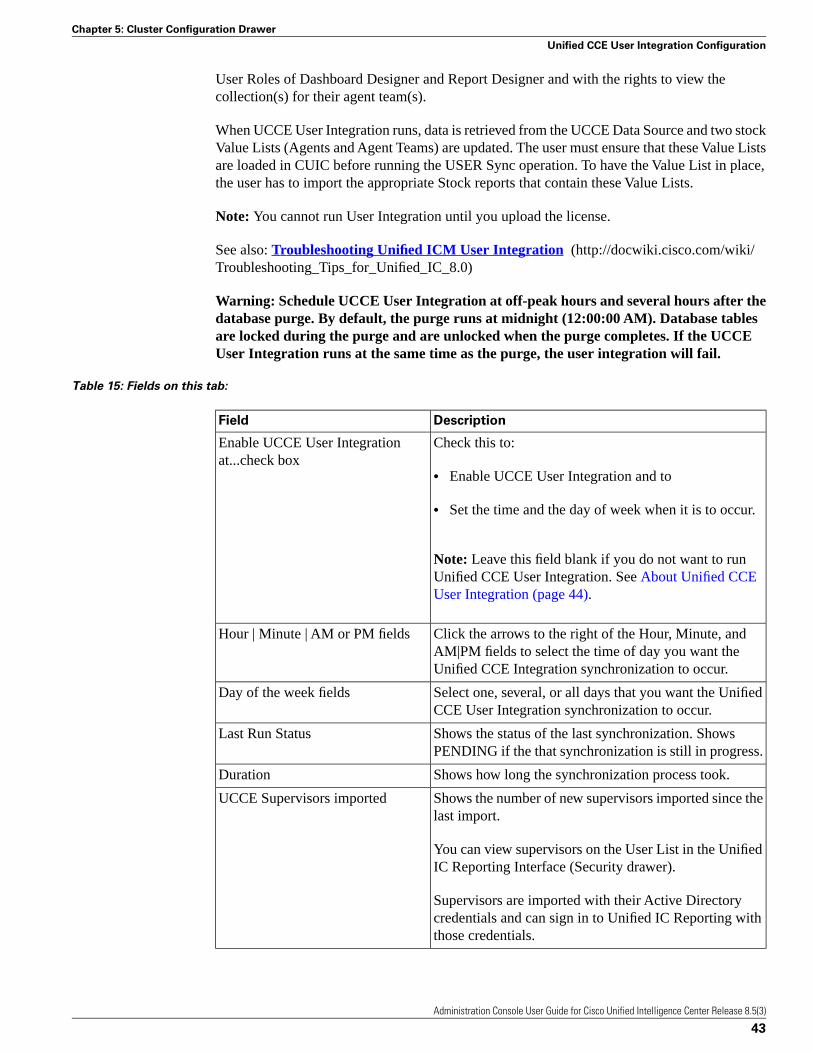
User Roles of Dashboard Designer and Report Designer and with the rights to view thecollection(s) for their agent team(s).
When UCCE User Integration runs, data is retrieved from the UCCE Data Source and two stockValue Lists (Agents and Agent Teams) are updated. The user must ensure that these Value Listsare loaded in CUIC before running the USER Sync operation. To have the Value List in place,the user has to import the appropriate Stock reports that contain these Value Lists.
Note: You cannot run User Integration until you upload the license.
See also: Troubleshooting Unified ICM User Integration (http://docwiki.cisco.com/wiki/Troubleshooting_Tips_for_Unified_IC_8.0)
Warning: Schedule UCCE User Integration at off-peak hours and several hours after thedatabase purge. By default, the purge runs at midnight (12:00:00 AM). Database tablesare locked during the purge and are unlocked when the purge completes. If the UCCEUser Integration runs at the same time as the purge, the user integration will fail.
Table 15: Fields on this tab:
DescriptionField
Check this to:Enable UCCE User Integrationat...check box
• Enable UCCE User Integration and to
• Set the time and the day of week when it is to occur.
Note: Leave this field blank if you do not want to runUnified CCE User Integration. See About Unified CCEUser Integration (page 44).
Click the arrows to the right of the Hour, Minute, andAM|PM fields to select the time of day you want theUnified CCE Integration synchronization to occur.
Hour | Minute | AM or PM fields
Select one, several, or all days that you want the UnifiedCCE User Integration synchronization to occur.
Day of the week fields
Shows the status of the last synchronization. ShowsPENDING if the that synchronization is still in progress.
Last Run Status
Shows how long the synchronization process took.Duration
Shows the number of new supervisors imported since thelast import.
UCCE Supervisors imported
You can view supervisors on the User List in the UnifiedIC Reporting Interface (Security drawer).
Supervisors are imported with their Active Directorycredentials and can sign in to Unified IC Reporting withthose credentials.
Administration Console User Guide for Cisco Unified Intelligence Center Release 8.5(3)
43
Chapter 5: Cluster Configuration Drawer
Unified CCE User Integration Configuration

DescriptionField
Shows a count of all teams updated. Teams areresynchronized on each run.
Team Collections Updated
Supervisors can view their Agents and Agent Teamscollections in the Value List drawer in the Unified ICReporting interface.
Actions on this tab:
• Synchronize Now - click this to run the user integration immediately. If the scheduledintegration is configured to run later in the day, this action runs the job now and still runs itat the scheduled time.
Clicking this button changes its appearance to Cancel Active Synchronization.
A message appears if another user is already running a synchronization.
This button is disabled if you have not yet applied a license.
• Save - Click to save your time and date settings.
• Refresh - Click to refresh the page to see changes that others might have made.
See also: About Unified CCE User Integration (page 44).
About Unified CCE User Integration
The Unified CCE User Integration feature imports supervisors and their teams from UnifiedICM/CCE from the Unified ICM Configuration Manager and database into Unified IC.
Supervisors are automatically given Unified IC user roles and can log in to Unified IC to accesscollections for - and run reports for - their agent team(s).
Note:
• You cannot run User Integration until you upload the license.
• There are five tasks in the initial setup for Unified CCE User Integration. Some are performedin the Administration interface. Some are performed in the Reporting interface. As SuperUsers have access to both interfaces, it is efficient for a Super User to set up UCCE UserIntegration.
The tasks are to:
• Enable Unified CCE User Integration in the Administration interface.
• Complete the configuration of the UCCE Historical Data Sourcein the Data Sources drawerof the Reporting Interface.
• Synchronize Users in the Administration Interface.
Administration Console User Guide for Cisco Unified Intelligence Center Release 8.5(3)
44
Chapter 5: Cluster Configuration Drawer
Unified CCE User Integration Configuration

• Validate Collections of Agents and Agent Teams in the Reporting Interface.
• Set up a synchronization schedule in the Administration Interface.
Results of Unified CCE User Integration:
• Integrated Supervisors can sign in to Unified IC Reporting (provided their Active Directoryauthentication has been configured.
• Integrated Supervisors are added to the Unified IC Reporting User List with the User Rolesof Report Designer and Dashboard Designer.
• The Unified IC Value Lists page is updated with Agents and Agent Teams collections.
• Integrated Supervisors can view their Agents and Agent Teams collections (Unified ICReporting > Value Lists drawer).
• Integrated Supervisors are granted permissions to Agents and Agent Teams collections only(Unified IC Reporting > Security drawer).
Once Unified CCE User Integration schedule is set up, Unified IC is updated with changes tosupervisors and their teams every time the synchronisation updates.
License File Management
To navigate to this page, click Cluster Configuration > License Management .
Use the License Management tab to upload and retrieve your Unified IC license. Once a licenseis uploaded, this tab displays information about the current license.
Unified IC uses a centralized licensing model, where the license file is uploaded to the Controllerthrough this interface and, based on License Type, is distributed to nodes in the cluster usingdatabase replication.
The license file is saved to the operating system, with its properties encrypted, as Cuic.lic.
If the member node is not online when the license file is replicated, Unified IC passes the licenseinformation when the member starts up.
Table 16: Fields on this page:
DescriptionField
The type of license - Standard, Premium, Lab, orTrial/Demo. See License Types (page 92).
Current License Type
The number of servers the license allows. For mostLicense Types, this shows 8.
Maximum number of devices in thiscluster Servers
Administration Console User Guide for Cisco Unified Intelligence Center Release 8.5(3)
45
Chapter 5: Cluster Configuration Drawer
License File Management

DescriptionField
For Demo License Types only, shows the date the licensebecame active.
Start Date
The date the license will expire. For most License Types,this shows Never expires. For Demo licenses, this showsthe date 90 days later than the Start date.
Expiration Date
For Lab License Types only, shows the maximum numberof logged in users per device (5).
User Count
Actions on this tab:
• Upload license file (Browse) - If you have no license, click Browse and navigate to the localdirectory where your license (*.lic file) is stored.
• Apply License - Click this to apply the license to all devices.
A message displays indicating that the license file was uploaded successfully and will bedistributed in the cluster in approximately one minute.
Note: The databases are polled once a minute for changes. The license replication is notimmediate but will occur within a minute.
• Retrieve - Click this to open a dialog box where you can choose to open the license file toreview it or to save it to your local drive. You might save if, for example, to have a backupcopy in the event that your original license is lost or corrupted.
See also:
Troubleshooting License Management (http://docwiki.cisco.com/wiki/Troubleshooting_Tips_for_Unified_IC_8.0)
How to Obtain Your License (page 91)
License Types (page 92)
Administration Console User Guide for Cisco Unified Intelligence Center Release 8.5(3)
46
Chapter 5: Cluster Configuration Drawer
License File Management

Network Management DrawerOpen this drawer to access the SNMP page.
This chapter contains the following topics:
• SNMP (Simple Network Management Protocol), page 47• Unified IC SNMP MIBs, page 48
SNMP (Simple Network Management Protocol)
To navigate to this page, click the Network Management drawer.
This page launches the Cisco Unified Serviceability application, which gives menu access forconfiguring SNMP-associated settings, such as community strings, users, and notificationdestinations for V1, V2c, and V3.
Open online help for SNMP configuration from within the Serviceability application.
Note: You cannot click the Back button on this page to return to the Unified Intelligence CenterAdministration console.
To return to the Administration console:
• Close the Cisco Unified Serviceability page, or
• Select Cisco Unified Intelligence Center in the Navigation dropdown at the top right of thescreen. Then click Go.
The Unified IC SNMP MIBs are documentented in the Administration Console User Guide forCisco Unified Intelligence Center. They are not documented in the Online help.
Administration Console User Guide for Cisco Unified Intelligence Center Release 8.5(3)
47
Chapter 6

Unified IC SNMP MIBs
The Unified IC SNMP sub-agent captures the following in a Management Information Base.All are scalar objects.
See also: Troubleshooting SNMP (http://docwiki.cisco.com/wiki/Troubleshooting_Tips_for_Unified_IC_8.0)
Unified IC MIB Structure
• MIBObjects (page 48)
– CuicGeneral Info (page 48)
– CuicLicenseInfo (page 49)
– CuicReporting (page 50)
– CuicReportScheduler (page 51)
– CuicDbInfo (page 51)
– CuicClusterInfo (page 52)
– CuicSecurity (page 52)
• MIB Notifications (page 53)
MIB Objects
The Cisco Unified IC MIB Objects are:
• CuicGeneralInfo (page 48)
• CuicLicenseInfo (page 49)
• CuicReporting (page 50)
• CuicReportScheduler (page 51)
• CuicDbInfo (page 51)
• CuicCluserInfo (page 52)
• CuicSecurity (page 52)
• CuicDataSourceInfo (page 52)
Administration Console User Guide for Cisco Unified Intelligence Center Release 8.5(3)
48
Chapter 6: Network Management Drawer
Unified IC SNMP MIBs

CuicGeneralInfo
This table contains a list of CUIC servers. An entry in this table represents a CUIC server inthis cluster.
A row is created in this table whenever a new server is added to the cluster. A row is deletedwhen a server is removed from the cluster.
DescriptionMIB
Host name for the Unified IC server as entered duringinstallation.
cuicGeneralInfoServerName
The description of the Unified IC application installedon this server, as entered for the application duringinstallation
cuicGeneralInfoServerDescription
The version number of the Unified IC softwareinstalled on the server displayed in the formatCUIC_<major>_<minor>_<buildnumber>.
cuicGeneralInfoVersion
This object indicates the starting time for the UnifiedIC application server.
cuicGeneralInfoStartTime
The time zone where the Unified IC server isphysically located.
cuicGeneralInfoTimeZoneName
The last known status of the applicationcuicGeneralInfoSystemStatus
Status of the reporting service:
• 'inService' = The service is up and runningoptimally, accepting connections.
• 'partialService' = Some of the componentscomprising the application are not running; theservice is in warning state.
• 'notresponding' = The service is either shut downor not responding.
• 'unknown' = The service status is unknown.
The URL for the Unified IC Administration operationsconsole web server.
cuicGeneralInfoOpsConsoleURL
This object specifies the notification status tomanagement station, to disable and alternatively enableoutbound notifications on this server.
cuicGeneralInfoEnableNotifications
Administration Console User Guide for Cisco Unified Intelligence Center Release 8.5(3)
49
Chapter 6: Network Management Drawer
Unified IC SNMP MIBs

CuicLicenseInfo
An entry in this table describes the Unified IC licensing details. A row is created in this tablewhenever a Unified license is installed on a server in this cluster.
DescriptionMIB
This object specifies the type of license installed.cuicLicenseInfoType
The timestamp for when the license was installed andapplied.
cuicLicenseInfoStartTime
The timestamp when the license will expire.cuicLicenseInfoStartTime
The host name of the Controller node where thelicense is installed. All other nodes in the cluster pointto the license on the Controller.
cuicLicenseInfoHost
CuicReporting
This table lists statistics of the Unified IC reporting nodes. A row is created in this table whennew server is being added to the cluster. A row is deleted when a server is removed from thiscluster."
DescriptionMIB
The number of Data Sources configured in theUnified IC reporting application.
cuicReportingDataSourceCount
The last known status of the reporting engine:cuicReportingEngineStatus
• 'running' = Service is running and can fetchdata from data source
• 'stopped' = Service is shutdown.
• 'unknown' = The status is unknown.
The number of historical report definitionsinstalled on the CUIC application.
cuicReportingHistoricalReportDefinitionCount
A report definition is template for a report. Eachreport has an association with a report definition.
The number of real time report definitionsinstalled on the CUIC application.
cuicReportingRealTimeReportDefinitionCount
The number of historical reports that arecurrently running.
cuicReportingHistoricalReportRunning
The number of historical reports that arecurrently waiting to execute.
cuicReportingHistoricalReportWaiting
The total number of historical reports that havebeen launched since the server last started.
cuicReportingTotalKickedOffHistoricalReports
Administration Console User Guide for Cisco Unified Intelligence Center Release 8.5(3)
50
Chapter 6: Network Management Drawer
Unified IC SNMP MIBs

DescriptionMIB
Number of real time reports currently running.cuicReportingRealTimeReportRunning
The number of real time reports that arecurrently waiting to be executed.
cuicReportingRealTimeReportWaiting
Number of real time reports run since server laststarted.
cuicReportingTotalKickedOffRealTimeReports
CuicReportScheduler
This table lists Report Scheduler health and statistics. A row iscreated in this table wheneverthe Scheduler Component is enabled on a server in this cluster.
DescriptionMIB
The status of the reporting scheduler engine:cuicSchedulerStatus
• 'running' = Service is running and can generatea report on execution
• 'stopped' = Service is shutdown.
• 'unknown' = The status is unknown.
The status of the email server:cuicSchedulerEmailServerStatus
• 'running' = Service is running and can send email
• 'stopped' = Service is shutdown.
• 'unknown' = The status is unknown.
The number of jobs that the scheduler service hascompleted since the server started.
cuicSchedulerJobsCompletedCount
The number of jobs that the scheduler service iscurrently running. Note that this counter is not thenumber of reports scheduled.
cuicSchedulerJobsRunningCount
The number of jobs that the scheduler service hasfailed to complete successfully
cuicSchedulerJobsFailedCount
CuicDbInfo
This table gives the status of the Unified IC database (cuic_data) and some perfmon counters.
The cuidatabase exists on each node in the cluster and stores reports and configurations. Thesystem replicates each cuicdatabase to other servers in a cluster.
A row is created in this table whenever a server is added to the cluster. A row is deleted whena server is removed from the cluster.
Administration Console User Guide for Cisco Unified Intelligence Center Release 8.5(3)
51
Chapter 6: Network Management Drawer
Unified IC SNMP MIBs

DescriptionMIB
The status of the database server:cuicDbInfoStatus
• 'running' = The database server is up andrunning
• 'stopped' = The database server is shutdown.
• 'unknown' = The database server is unknown.
The status of the last replication operation:cuicDbInfoReplicationStatus
• 'success' = Replication performed succesfully.
'fail' = Replication failed.
• 'unknown' = Failed to get replication status.
The number megabytes of disk space used. Thevalue is in MB.
cuicDbInfoTmpSpaceUsed
The number megabytes of temporary space used.The value is in MB."
cuicDbInfoSpaceUsed
CuicClusterInfo
This table describes the Unified IC cluster.
DescriptionMIB
The unique name of cluster, which helps inassociating a device with the cluster.
cuicClusterName
Number of Unified IC servers in the clustercuicClusterServerCount
The hostname of the first node in the cluster. Thisis the Controller (publisher) node.
cuicClusterFirstNodeName
CuicSecurity
This table gives information about Users and User Groups.
DescriptionMIB
The number of users that have been created toaccess Unified IC
cuicSecurityUsersConfigured
The number of users currently signed in.cuicSecurityUsersLoggedIn
The number of rejected login attempts.cuicSecurityLoginFailedAttempts
The number of user groups created on this server.cuicSecurityGroupsConfigured
Administration Console User Guide for Cisco Unified Intelligence Center Release 8.5(3)
52
Chapter 6: Network Management Drawer
Unified IC SNMP MIBs

CuicDataSourceInfo
This table gives information for the data source from that populates a report.
An entry in this table describes a data source configured on the Unified IC server. A row iscreated in this table when a new data source is configured on the server. A row is deleted whena configured data source is removed from the server.
Table 17: CuicDataSourceInfo MIB Objects
The name of the data source configured.cuicDatasourceName
The status of the data source:cuicDatasourceStatus
• 'online' = The data source is connected, and itis online.
• 'offline' = The data source is disconnected, andit is offline.
• unknown' = The data source connectivity statusis unknown.
The host name of the database server.cuicDatasourceHost
The data source type:cuicDatasourceType
• 'mssql' = MS SQL datasource.
• 'informix' = IBM Informix datasource.
• 'other' = Unknown datasource.
MIB Notifications (CUIC TRAPs)
Trap notifications are sent by Unified IC when unusual conditions occur that can potentiallyaffect the functioning of a Unified IC service. Each Notification describes the operation stateinformation of a service when the condition occurs. Review traps to review information onissues occurring on the network element without polling for SNMP objects.
Unified IC supports a generic trap and raises SNMP traps on the following events:
• Database service going offline
• DB Replication failure
• Failing to run a scheduled report.
• Report execution failure
Administration Console User Guide for Cisco Unified Intelligence Center Release 8.5(3)
53
Chapter 6: Network Management Drawer
Unified IC SNMP MIBs

Table 18: Unified IC Notification Event attributes:
The unique notification message identifier assignedby the Unified IC application. This identifier is
cuicEventId
unique for each different notification but consistentfor each instance of the same notification.
The host name or the fully qualified domain nameof the Unified IC server from which this eventoriginated.
cuicEventHostName
The service-specific name of the functional servicethat generated this notification.
cuicEventAppName
The service-specific name of the Unified IC servicenotification message, used to group and correlatesimilar notifications.
cuicEventName
The state (not to be confused with severity) of thenotification and potentially the current state of the
cuicEventState
functional component that generated thenotification.
Values are:
• 'raise' = Identifies a notification received as aresult of a health-impacting condition, such asa process failure. A subsequent clear statenotification will follow when the error conditionis resolved.
• 'clear' = indicates that the condition whichgenerated a previous raise notification has beenresolved.
The severity level of this notification. The severitylevels are:
cuicEventSeverity
• 'emergency'= A devastating failure has occurred;the system or service is unusable. Immediateoperator intervention is required.
• 'alert' = A devastating failure is imminent thatwill render the system unusable. Immediateoperator attention is necessary.
• 'critical' = A service-mpacting failure is likelyto occur soon; an error has occurred that wasnot appropriately handled by the system.Operator attention is needed as soon as possible.
• 'error' = Contains important operational stateinformation and may indicate that the systemhas experienced a temporary impairment or an
Administration Console User Guide for Cisco Unified Intelligence Center Release 8.5(3)
54
Chapter 6: Network Management Drawer
Unified IC SNMP MIBs

error that was appropriately handled by thesystem. An operator should review thenotification soon to determine if action isneeded.
• 'warning' = Contains important operational stateinformation that may be a precursor to an erroroccurrence. An operator should review thenotification soon to determine if action isneeded.
• 'notice' = Contains health or operational stateinformation that may be pertinent to the healthof the system but does not require the attentionof the administrator at this time.
• 'informational' = Contains interestingsystem-level information that is valuable to anadministrator, however, the event itself does notindicate a failure or impairment condition.
• 'debug' = Provides supplemental informationthat may be beneficial toward diagnosing orresolving a problem but does not in itself provideoperational health status.
The date and time that the notification wasgenerated on the originating device.
cuicEventTimestamp
The full text of the notification. This text includesa description of the event that was generated,
cuicEventText
component state information, and potentially a briefdescription of administrative action that may benecessary to correct the condition that caused theevent to occur.
ThreadPool Events
The thread pool information group defines the set of objects for the Unified reporting enginethread pool. All servers populate these objects.
DescriptionObject
The maximum number of threads available to the Unified IC webserver thread pool manager.
ThreadsMaxAvailable
The number of threads that are currently running tasks.ThreadsRunning
This counter is useful in monitoring performance of the server. Ifthe number of threads is close to the maximum available, then thenext reporting request must wait until a thread becomes free.
Administration Console User Guide for Cisco Unified Intelligence Center Release 8.5(3)
55
Chapter 6: Network Management Drawer
Unified IC SNMP MIBs

DescriptionObject
the number of queued tasks. A task is a job, performed by one ormore thread
QueuedTasks
The maximum number of queued tasks.QueuedTasksMax
EnvInfo Events
The EnvInfo group defines the set of objects for the Runtime tomcat info. All servers populatethese objects.
DescriptionObject
The total number of HTTP errors (for example, 401 Unauthorized)encountered by a Unified IC web application
WaErrors
The number of currently active (in use) sessions for the webapplication.
WaSessionsActive
The percentage of CPU utilized by the Tomcat JVM. This object isfor the Unified IC Tomcat JVM object
JvmPercentCPUTime
The amount of free dynamic memory in the Unified IC Tomcat JavaVirtual Machine.
JvmMemoryFree
The Tomcat Java Virtual Machine current total dynamic memory,including free and in-use memory.
JvmMemoryTotal
The Unified IC Tomcat Java Virtual Machine maximum dynamicsize.
JvmMemoryMax
The Unified IC Tomcat Connector's current number of busy/in-userequest processing threads.
TomcatThreadsBusy
The Unified IC tomcat connector's current total number of requestprocessing threads, including available and in-use threads
TomcatThreadsTotal
This object indicates the Connector maximum number of requestprocessing threads. Each incoming request on a Unified IC web page
TomcatThreadsMax
requires a thread for the duration of that request. If more simultaneousrequests are received than can be handled by the currently availablerequest processing threads, additional threads will be created up tothe configured maximum shown in this counter
Administration Console User Guide for Cisco Unified Intelligence Center Release 8.5(3)
56
Chapter 6: Network Management Drawer
Unified IC SNMP MIBs
Tools Drawer
RTMT
The RTMP Plugin Download page includes a link to download the Real Time Monitoring Tool(RTMT).
RTMT runs as a client-side application and can be installed on a Windows workstation. It iscluster-aware and provides critical service and performance monitoring (perfmon), trace/logcollection and viewing, and Alert Management on the node for the IP address you request whenyou launch the RTMT. It does not provide the status of all critical applications on all the nodesat the same time.
Use RTMT to:
• Monitor the health of the system by generating email alerts for objects whose values go aboveor below a threshold,
• Collect and view traces,
• View syslog messages, and
• Monitor performance counters.
RTMT has extensive online help. Refer to it for information on alerts, schedule collection,performance monitoring, and collecting and downloading tracing and logging data.
See also: Download and Launch RTMT (page 58).
Troubleshooting RTMT (http://docwiki.cisco.com/wiki/Troubleshooting_Tips_for_Unified_IC_8.0)
Administration Console User Guide for Cisco Unified Intelligence Center Release 8.5(3)
57
Chapter 7

Download and Launch RTMT
On the download page:
1. Select the Windows platform.
2. Click Download.
3. Run the file or save the CuicServRtmtPlugin executable file and then run it from the savedlocation.
4. Follow the prompts and click the buttons on the installation screens.
To launch:
1. Launch RTMT from the desktop icon.
Figure 8: RTMT Desktop Icon
2. In the Host IP Address field, enter the IP address for the node you want to monitor.
3. Enter the User Name and Password for a Super User. (Only a Super User can installRTMT.)
4. Accept the default port (8443).
5. Check Secure Connection.
You see an error if the Host IP Address is not found or there is no network connection.
6. Click Yes to accept the certificate.
7. Click OK to accept the default configuration.
Note: The performance counters are documented in the Administration Console User Guidefor Cisco Unified Intelligence Center. They are not documented in the Online help.
Required Services for Supporting the RTMT Client
RTMT users the following services/servlets:
• Cisco AMC service
• Cisco Unified Serviceability RTMT
Administration Console User Guide for Cisco Unified Intelligence Center Release 8.5(3)
58
Chapter 7: Tools Drawer
RTMT

• Cisco RIS Data Collector
• Cisco Tomcat Stats Servlet
• Cisco Trace Collection Service
• Cisco Log Partition Monitoring tool
• Cisco SOAP-Real_Time Service APIs
• Cisco-SOAP-Performance Monitoring APIs
• Cisco RTMT Reporter servlet
• Cisco Serviceability Reporter
Manage these services from the Cisco Unified Serviceability (page ?) application.
RTMT Integration with Unified IC
Tracing and Logging
Unified IC exposes tracing and logging information through the Tools > Trace & Log Centralinterface. The RTMT tool gives you the ability to browse through a trace file and supportson-demand or scheduled downloading of the file.
Figure 9: RTMTTraceLog
Critical Services.
Unified IC exposes service information through the RTMT Critical Services interface.
Administration Console User Guide for Cisco Unified Intelligence Center Release 8.5(3)
59
Chapter 7: Tools Drawer
RTMT

Figure 10: RTMT Critical Services
Alerts.
Unified IC exposes perfmon information and statistics through the RTMT Tools > Alert Centralinterface.
Figure 11: RTMT Alerts
Perfmon and Statistics.
Unified IC exposes perfmon information and statistics through the RTMT Performance interface.
Administration Console User Guide for Cisco Unified Intelligence Center Release 8.5(3)
60
Chapter 7: Tools Drawer
RTMT

Figure 12: RTMT Performance Interface
The RTMT Interface
The RTMT system monitoring objects on the left panel of the RTMT page are:
• System Summary
Displays information on Virtual Memory usage, CPU usage, Common Partition usage, andthe alert history log
• Server
Server objects are:
– CPU and Memory - Displays information on CPU usage and Virtual memory usage forthe server.
– Process - Displays information on the processes running on the server.
– Disk Usage - Displays information on disk usage on the server.
Administration Console User Guide for Cisco Unified Intelligence Center Release 8.5(3)
61
Chapter 7: Tools Drawer
RTMT

– Critical Services - Displays the name of the critical service, the status (whether the serviceis up, down, activated, stopped by the administrator, starting, stopping, or in an unknownstate), and the elapsed time during which the services have existed in a particular state forthe server or for a particular - server in a cluster (if applicable).
To view the CUIC Services, click the tab for a Intelligence Center node. See Unified ICCounters (page 65).
• Performance
Performance monitoring allows you to:
– Monitor performance counters related to the system and to the Unified IC application.
– Continuously monitor a set of preconfigured objects and receive notification in the formof an email message.
– Associate counter threshold settings to alert notification.
– Save and restore settings, such as counters being monitored, threshold settings, and alertnotifications, for customized troubleshooting tasks.
– Display up to six perfmon counters in one chart for performance comparisons.
– Use performance queries to add a counter to monitor.
Performance objects are:
– CPU and Memory - Displays information on CPU usage and Virtual memory usage forthe server.
– Process - Displays information on the processes running on the server.
– Disk Usage - Displays information on disk usage on the server.
– Critical Services - Displays the name of the critical service, the status (whether the serviceis up, down, activated, stopped by the administrator, starting, stopping, or in an unknownstate), and the elapsed time during which the services have existed in a particular state forthe server or for a particular server in a cluster (if applicable).
To view the CUIC Services, click the tab for a Intelligence Center node. See Unified ICCounters (page 65).
• Performance Log Viewer
The Performance Log Viewer displays data for counters from perfmon CSV log files in agraphical format.
• Tools
Tools objects are:
Administration Console User Guide for Cisco Unified Intelligence Center Release 8.5(3)
62
Chapter 7: Tools Drawer
RTMT

– Alert Central - displays the history and current status of every alert in the system. Clickthe Intelligence Center tab to see Unified IC alerts.
Trace & Log Central
– Allows you to configure on-demand trace collections for a specific date range or absolutetim
Job Status
– Shows the status of trace collection events.
Syslog Viewer
– Use to view, by node, the system, application, and security logs.
Unified IC Performance Objects and Counters
Unified IC performance objects are named for system components that generate data. Eachperformance object provides performance counters that represent data for specific to that object.For example, the CUIC Licensing performance object has counters for License Start and LicenseExpiration dates. The CUIC Reporting object has counters for the number of reports that arerunning and the number of reports that have failed. The counters for each object display whenthe folder expands.
Reporting Counters. The following diagram illustrates the runtime interactions and therelationship among the components involved on the execution of a report. The diagram providesa simple structure that defines the reporting engine performance counters.
Administration Console User Guide for Cisco Unified Intelligence Center Release 8.5(3)
63
Chapter 7: Tools Drawer
RTMT

Figure 13: Report Execution
When the data for the report is available, the Data Processing Center computes the formulafields and global report footers. The gauge, grid, and chart managers in the engine pre-processthe data to generate subsets of information that will be consumed by their corresponding peercomponents on the User Interface. The diagram shows which processes have a high cost ofexecution and the importance of closely monitoring the operations performed by charts, grids,data processing center, the data sources, and so forth. Monitor these components to track thebehavior of each component and its total contribution to the cost of executing a report.
Aggregating the costs of all components provides a holistic view of the system performance.Keeping counters at the component level allows the system and application administrator todrill down into the details to determine what each component is doing and to perform anynecessary corrective actions that.
This section lists all the performance objects monitored for Unified IC and explains the countersfor each.
Note: Online help is available for each counter. Right-click the counter and select CounterDescription.
Administration Console User Guide for Cisco Unified Intelligence Center Release 8.5(3)
64
Chapter 7: Tools Drawer
RTMT

Figure 14: RTMT Counter Help
For information on the objects and counters that are kept for the operating system, refer to theRTMT online help.
Unified IC Counters
Counters:
• CUIC Tomcat Connector (page 66)
• CUIC Tomcat JVM (page 67)
• CUIC Tomcat Web Application (page 67)
• DB Change Notification Client (page 67)
• DB Change Notification Server (page 68)
• DB Local DSN (page 69)
• DB User Host Information Counters (page 69)
• DB Performance Info (page 69)
• Enterprise Replication DBSpace Monitors (page 69)
• Enterprise Replication Perfmon Counters (page 69)
• Intelligence Center General Information section (page 70)
• Intelligence Center JVM Statistics (page 70)
• Intelligence Center License Information section (page 71)
Administration Console User Guide for Cisco Unified Intelligence Center Release 8.5(3)
65
Chapter 7: Tools Drawer
RTMT

• Intelligence Center System Condition Table (page 71)
• Intelligence Center Thread Pool section (page 73)
• IP (page 73)
• IP6 (page 74)
• Memory (page 75)
• Network Interface (page 77)
• Number of Replicates Created and State of Replication (page 78)
• Partition (page 79)
• Process (page 80)
• Processor (page 81)
• Ramfs (page 81)
• Reporting Engine Info (page 81)
• SchedulerInfo (page 85)
• System (page 85)
• TCP (page 86)
• Thread (page 87)
CUIC Tomcat Connector
The Tomcat Connector object provides information about Tomcat non-secure and secureHypertext Transport Protocol (HTTP) connectors. A Tomcat Connector represents an endpointthat receives requests and sends responses.
The Connector handles HTTP/HTTPS requests and sends HTTP/HTTPS responses that occurwhen Cisco Unified Intelligence Center web pages are accessed. There are two instances of thisobject based on the Secure Sockets Layer (SSL) status of the URLs for web applications:http-8443 for SSL (HTTPS) connections and http-8081 for non-SSL (HTTP) connections
DescriptionCounter
The total number of HTTP errors (for example, 401 Unauthorized )encountered by the Connector.
Errors
The total number of data received by the Connector.MBytes Received
The total number of data that the Connector has sent.MBytes Sent
The total number of requests that have been handled by the Connector.Requests
Administration Console User Guide for Cisco Unified Intelligence Center Release 8.5(3)
66
Chapter 7: Tools Drawer
RTMT

DescriptionCounter
The Connector's current number of busy/in-use request processingthreads.
ThreadsBusy
The Connector's maximum number of request processing threads.ThreadsMax
The Connector's current total number of request processing threads,including available and in-use threads.
ThreadsTotal
CUIC Tomcat JVM
The Tomcat Java Virtual Machine (JVM) object provides information about the Tomcat JVM,which represents, among other things, a pool of common resource memory used by Unified IC.
DescriptionCounter
The amount of free dynamic memory block (heap memory) inthe Tomcat Java Virtual Machine. The dynamic memory block
KBytesMemoryFree
stores all objects created by Tomcat and its web applicationssuch as Cisco Unified Intelligence Center. When the amountof free dynamic memory is low, more memory is automaticallyallocated and total memory size (represented by theKbytesMemoryTotal counter) increases up to the maximum(represented by the KbytesMemoryMax counter). You candetermine the amount of memory in use by subtractingKBytesMemoryFree from KbytesMemoryTotal.
The maximum dynamic memory block size for the Unified ICTomcat Java Virtual Machine.
MemoryMax
This current total dynamic memory block size - including freeand in-use memory - for the Tomcat Java Virtual Machine.
MemoryTotal
CUIC Tomcat Web Application
The Tomcat Web Application object provides information about running Cisco UnifiedIntelligence Center. The instance name for each Tomcat Web Application is based on the URLfor the web application.
DescriptionCounter
The total number of HTTP errors (for example, 401Unauthorized) encountered by a Cisco Unified IntelligenceCenter (CUIC)-related web application.
Errors
The total number of requests handled by the web application.Each time a web application is accessed, its Requests counterincrements accordingly.
Requests
The number of currently active (in use) sessions the webapplication currently has.
Sessions Active
Administration Console User Guide for Cisco Unified Intelligence Center Release 8.5(3)
67
Chapter 7: Tools Drawer
RTMT

DB Change Notification Client
DescriptionCounter
The number of database change notifications that have beenprocessed. This counter refreshes every 15 seconds by default.
MessagesProcessed
The number of change notification messages in the changenotification queue for this client that are currently being
MessagesProcessing
processed or are waiting to be processed. This counterrefreshes every 15 seconds by default.
The head pointer of the change notification queue. The headpointer is the starting point in the change notification queue.
QueueHeadCounter
To determine the number of notifications in the queue, subtractthe head pointer value from the tail pointer value. This counterrefreshes every 15 seconds by default.
The largest number of change notification messages to beprocessed for this client. This counter is cumulative since thelast restart of the Cisco Database Layer Monitor service.
QueueMax
The tail pointer of change notification queue. The tail pointerrepresents the ending point in the change notification queue.
QueueTailPointer
To determine the number of notifications in the queue, subtractthe head pointer value from the tail pointer value. This counterrefreshes every 15 seconds by default.
The number of tables to which this client has subscribed.TablesSubscribed
DB Change Notification Server
DescriptionCounter
The total number of change notification clients.Clients
The total number of change notification messages processedby server since reboot.
CNProcessed
The number of seconds that the change notification processhas messages to process, but is not processing them. This
QueueDelay
condition is true if either Change Notification RequestsQueued in Database (QueuedRequestsInDB) and ChangeNotification Requests Queued in Memory(QueuedRequestsInMemory) are non-zero - or if - the LatestChange Notification Messages Processed count is notchanging. This condition is checked every 15 seconds.
The number of records from DBCNQueue table.QueuedRequestsInDB
The number of change notification requests queued inmemory.
QueuedRequestsInMemory
Administration Console User Guide for Cisco Unified Intelligence Center Release 8.5(3)
68
Chapter 7: Tools Drawer
RTMT

DB Change Notification Subscriptions
DescriptionCounter
The table(s) for which the service or servlet will receivechange notifications. This information is provided forinformational purposes only; no counter will increment.
SubscribedTable
DB Local DSN
DescriptionCounter
The amount of ccm dbspace consumed.CcmDbSpace_Used
The amount of ccmtemp dbspace consumed.CcmtempDbSpace_Used
The percentage of CN dbspace consumed.CNDbSpace_Used
The data source name (DSN) that is being referenced fromthe local machine.
Local DSN
The amount of root dbspace consumed.RootDBSpaceUsed
Total shared memory that is free.SharedMemory_Free
Total shared memory that is usedSharedMemory_Used
DB User Host Information Counters
DescriptionCounter
The number of connections that are present for each instanceof DB:User:Host.
DB:User:Host Instances
DBPerformance Info
DescriptionCounter
The amount of CUIC dbspace conCuicDbSpace_Used
The amount of CUIC Blob Space consumed.CuicSbSpace_Used
The amount of CUIC Temp dbspace consumed.CuicTempDbSpace_Used
The amount of root dbspace consumed.RootDbSpace_Used
Enterprise Replication DBSpace Monitors
DescriptionCounter
The amount of enterprise replication DbSpace consumed.ERDbSpace_Used
The amount of ERDbSpace consumed.ERSBDbSpace_Used
Administration Console User Guide for Cisco Unified Intelligence Center Release 8.5(3)
69
Chapter 7: Tools Drawer
RTMT
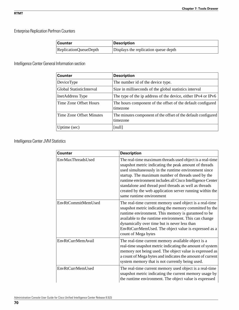
Enterprise Replication Perfmon Counters
DescriptionCounter
Displays the replication queue depthReplicationQueueDepth
Intelligence Center General Information section
DescriptionCounter
The number id of the device type.DeviceType
Size in milliseconds of the global statistics intervalGlobal StatisticInterval
The type of the ip address of the device, either IPv4 or IPv6InetAddress Type
The hours component of the offset of the default configuredtimezone
Time Zone Offset Hours
The minutes component of the offset of the default configuredtimezone
Time Zone Offset Minutes
[null]Uptime (sec)
Intelligence Center JVM Statistics
DescriptionCounter
The real-time maximum threads used object is a real-timesnapshot metric indicating the peak amount of threads
EnvMaxThreadsUsed
used simultaneously in the runtime environment sincestartup. The maximum number of threads used by theruntime environment includes all Cisco Intelligence Centerstandalone and thread pool threads as well as threadscreated by the web application server running within thesame runtime environment
The real-time current memory used object is a real-timesnapshot metric indicating the memory committed by the
EnvRtCommitMemUsed
runtime environment. This memory is guranteed to beavailable to the runtime environment. This can changedynamically over time but is never less thanEnvRtCurrMemUsed. The object value is expressed as acount of Mega bytes
The real-time current memory available object is areal-time snapshot metric indicating the amount of system
EnvRtCurrMemAvail
memory not being used. The object value is expressed asa count of Mega bytes and indicates the amount of currentsystem memory that is not currently being used.
The real-time current memory used object is a real-timesnapshot metric indicating the current memory usage by
EnvRtCurrMemUsed
the runtime environment. The object value is expressed
Administration Console User Guide for Cisco Unified Intelligence Center Release 8.5(3)
70
Chapter 7: Tools Drawer
RTMT

DescriptionCounter
as a count of Mega bytes and indicates the current amountof memory used by this runtime environment.
The real-time current threads in use object is a real-timesnapshot metric indicating a count of threads that are in
EnvRtCurrThreadsInUse
use in the runtime environment. The number of threadsin use by the runtime environment include all of the CiscoIntelligence Center standalone and thread pool threads aswell as those threads created by the web application serverrunning within the same runtime environment.
The real-time maximum memory available object is areal-time snapshot metric indicating the maximum amount
EnvRtMaxMemAvail
of System memory available. The object value is expressesas a count of Mega bytes
The real-time maximum memory used object is a real-timesnapshot metric indicating the peak memory allocated to
EnvRtMaxMemUsed
the runtime environment. The object value is expressedas a count of Mega bytes and indicates the high watermark of memory that can be used bye the runtimeenvironment
The real-time up time object is a real-time snapshot metricindicating how long the Cisco Intelligence Center
EnvRtUpTime
application has been running. The object value isexpressed as a count of milliseconds that have elapsedsince the application began executing
Intelligence Center License Information section
DescriptionCounter
The number of concurrent nodes this license enablesNode Count
The number of concurrent users this license enablesUser Count
Intelligence Center System Condition Table
DescriptionCounter
This counter is no longer valid with thecounter value -1. It has been renderedobsolete by the Await Write Time counter.
CUIC_DATASOURCE _UNAVAILABLE
Database replication failedCUIC_DB_REPLICATION _FAILED
CUIC Application license has expiredCUIC_LICENSE_EXPIRED
Could not run the report. Could be becauseassociated datasource is offline
CUIC_REPORT_ EXECUTION_FAILED
Service going downCUIC_SERVICE_UNAVAILABLE
Administration Console User Guide for Cisco Unified Intelligence Center Release 8.5(3)
71
Chapter 7: Tools Drawer
RTMT
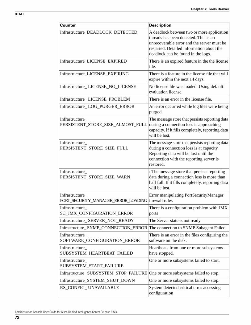
DescriptionCounter
A deadlock between two or more applicationthreads has been detected. This is an
Infrastructure_DEADLOCK_DETECTED
unrecoverable error and the server must berestarted. Detailed information about thedeadlock can be found in the logs.
There is an expired feature in the the licensefile.
Infrastructure_LICENSE_EXPIRED
There is a feature in the license file that willexpire within the next 14 days
Infrastructure_LICENSE_EXPIRING
No license file was loaded. Using defaultevaluation license.
Infrastructure_ LICENSE_NO_LICENSE
There is an error in the license file.Infrastructure_ LICENSE_PROBLEM
An error occurred while log files were beingpurged.
Infrastructure_ LOG_PURGER_ERROR
The message store that persists reporting dataduring a connection loss is approaching
Infrastructure_PERSISTENT_STORE_SIZE_ALMOST_FULL
capacity. If it fills completely, reporting datawill be lost.
The message store that persists reporting dataduring a connection loss is at capacity.
Infrastructure_PERSISTENT_STORE_SIZE_FULL
Reporting data will be lost until theconnection with the reporting server isrestored.
: The message store that persists reportingdata during a connection loss is more than
Infrastructure_PERSISTENT_STORE_SIZE_WARN
half full. If it fills completely, reporting datawill be lost.
Error manipulating PortSecurityManagerfirewall rules
Infrastructure_PORT_SECURITY_MANAGER_ERROR_LOADING
There is a configuration problem with JMXports
Infrastructure_SC_JMX_CONFIGURATION_ERROR
The Server state is not readyInfrastructure_ SERVER_NOT_READY
The connection to SNMP Subagent Failed.Infrastructure_ SNMP_CONNECTION_ERROR
There is an error in the files configuring thesoftware on the disk.
Infrastructure_SOFTWARE_CONFIGURATION_ERROR
Heartbeats from one or more subsystemshave stopped.
Infrastructure_SUBSYSTEM_HEARTBEAT_FAILED
One or more subsystems failed to start.Infrastructure_SUBSYSTEM_START_FAILURE
One or more subsystems failed to stop.Infrastructure_ SUBSYSTEM_STOP_FAILURE
One or more subsystems failed to stop.Infrastructure_SYSTEM_SHUT_DOWN
System detected critical error accessingconfiguration
RS_CONFIG_ UNAVAILABLE
Administration Console User Guide for Cisco Unified Intelligence Center Release 8.5(3)
72
Chapter 7: Tools Drawer
RTMT

DescriptionCounter
System detected critical error with databaseRS_DATABASE_ UNAVAILABLE
System has detected maintenance in progresson Reporting Server
RS_MAINTENANCE_ IN_PROGRESS
System has detected a critical systemthreshold reached on Reporting Server
RS_SYSTEM_ THRESHOLD_REACHED
System has detected an internal error withinReporting Server which may prevent it from
RS_UNRECOVERABLE _ERROR
functioning correctly. Restart may berequired.
Intelligence Center Thread Pool Section
DescriptionCounter
Number of threads currently executing a task.Active Thread Count
Minumum number of threads the thread pool is configured tohave.
Core Pool Size
The largest number of threads that have ever simultaneouslybeen in the pool.
Largest Pool Size
Maximum number of threads to which the thread pool cangrow.
Maximum Pool Size
Number of currently available threads. Calculated from (totalpool size) - (number of active threads)
Pool Size
The number of tasks currently queued for execution waitingfor a thread.
Task Queue Size
IP
The IP object provides information on the IPv4-related statistics on your system.
DescriptionCounter
The number of IP datagrams fragments that have beengenerated at this entity.
Frag Creates
The number of IP datagrams that were discarded at this entitybecause the datagrams could not be fragmented, such asdatagrams where the Do not Fragment flag was set.
Frag Fails
The number of IP datagrams that were successfully fragmentedat this entity
Frag OKs
The number of input datagrams that were delivered to IP userprotocols. This includes Internet Control Message Protocol(ICMP).
In Delivers
The number of input IP datagrams where no problems wereencountered, but which were discarded. Lack of buffer space
In Discards
Administration Console User Guide for Cisco Unified Intelligence Center Release 8.5(3)
73
Chapter 7: Tools Drawer
RTMT

DescriptionCounter
provides one possible reason. This counter does not includeany datagrams that were discarded while awaiting reassembly.
The number of input datagrams that were discarded withheader errors. This includes bad checksums, version number
In HdrErrors
mismatch, other format errors, time-to-live exceeded, andother errors that were discovered in processing their IP options.
The number of input datagrams that were received from allnetwork interfaces. This counter includes datagrams that werereceived with errors
In Receives
The number of locally addressed datagrams that were receivedsuccessfully but discarded because of an unknown orunsupported protocol.
In UnknownProtos
The number of incoming IP datagrams that were received andthe number of outgoing IP datagrams that were sent.
InOut Requests
The number of output IP datagrams that were not transmittedand were discarded. Lack of buffer space provides one possiblereason.
Out Discards
The total number of IP datagrams that local IP user-protocols(including ICMP) supply to IP in requests transmission. This
Out Requests
counter does not include any datagrams that were counted inForwDatagrams.
The number of IP reassembly failures that the IP reassemblyalgorithm detected, including time outs, errors, and so on.
Reasm Fails
This counter does not represent the discarded IP fragmentsbecause some algorithms, such as the algorithm in RFC 815,can lose track of the number of fragments because it combinesthem as they are received.
The number of IP datagrams that were successfullyreassembled.
Reasm OKs
The number of IP fragments that were received that requiredreassembly at this entity.
Reasm Reqds
IP6
The IP6 object, which supports Cisco Unified Communications Manager, provides informationon the IPv6-related statistics on your system.
DescriptionCounter
The number of IP datagrams fragments that have beengenerated at this entity.
Frag Creates
The number of IP datagrams that were discarded at this entitybecause the datagrams could not be fragmented, such asdatagrams where the Do not Fragment flag was set.
Frag Fails
Administration Console User Guide for Cisco Unified Intelligence Center Release 8.5(3)
74
Chapter 7: Tools Drawer
RTMT

DescriptionCounter
The number of IP datagrams that were successfully fragmentedat this entity
Frag OKs
The number of input datagrams that were delivered to IP userprotocols. This includes Internet Control Message Protocol(ICMP).
In Delivers
The number of input IP datagrams where no problems wereencountered, but which were discarded. Lack of buffer space
In Discards
provides one possible reason. This counter does not includeany datagrams that were discarded while awaiting reassembly.
The number of input datagrams that were discarded with headererrors. This includes bad checksums, version number mismatch,
In HdrErrors
other format errors, time-to-live exceeded, and other errorsthat were discovered in processing their IP options.
The number of input datagrams that were received from allnetwork interfaces. This counter includes datagrams that werereceived with errors
In Receives
The number of locally addressed datagrams that were receivedsuccessfully but discarded because of an unknown orunsupported protocol.
In UnknownProtos
The number of incoming IP datagrams that were received andthe number of outgoing IP datagrams that were sent.
InOut Requests
The number of output IP datagrams that were not transmittedand were discarded. Lack of buffer space provides one possiblereason.
Out Discards
The total number of IP datagrams that local IP user-protocols(including ICMP) supply to IP in requests transmission. This
Out Requests
counter does not include any datagrams that were counted inForwDatagrams.
The number of IP reassembly failures that the IP reassemblyalgorithm detected, including time outs, errors, and so on. This
Reasm Fails
counter does not represent the discarded IP fragments becausesome algorithms, such as the algorithm in RFC 815, can losetrack of the number of fragments because it combines them asthey are received.
The number of IP datagrams that were successfullyreassembled.
Reasm OKs
The number of IP fragments that were received that requiredreassembly at this entity.
Reasm Reqds
Memory
The memory object provides information about the usage of physical memory and swap memoryon the server.
Administration Console User Guide for Cisco Unified Intelligence Center Release 8.5(3)
75
Chapter 7: Tools Drawer
RTMT

DescriptionCounter
Displays the system physical memory utilization as apercentage. The value of this counter equals (Total KBytes
% Mem Used
- Free KBytes - Buffers KBytes - Cached KBytes + SharedKBytes) / Total KBytes, which also corresponds to the UsedKBytes/Total KBytes.
The percentage of active pages.% Page Usage
The system virtual memory utilization as a percentage. Thevalue of this counter equals (Total KBytes - Free KBytes -
% VM Used
Buffers KBytes - Cached KBytes + Shared KBytes + UsedSwap KBytes) / (Total KBytes + Total Swap KBytes), whichalso corresponds to Used VM KBytes/Total VM KBytes.
The capacity of buffers in your system in kilobytes.Buffers KBytes
The amount of cached memory in kilobytes.Cached KBytes
The total amount of memory that is available in your systemin kilobytes.
Free KBytes
The amount of free swap space that is available in yoursystem in kilobytes.
Free Swap KBytes
The amount of free memory in the high region. Linux kernelsplits the virtual memory address space into memory regions.
HighFree
The high memory is memory above certain physical address,and its amount depends on the total memory and the type ofkernel on the system.
The total amount of memory in the high region.HighTotal
The free low (non-paged) memory for kernel.LowFree
The total low (non-paged) memory for kernel.LowTotal
This represents the number of page faults (major + minor)made by the system per second (post 2.5 kernels only). This
PageFaultsPerSec
is not a count of page faults that generate I/O, because somepage faults can be resolved without I/O.
This represents the number of major faults the system hasmade per second, those which have required loading amemory page from disk (post 2.5 kernels only).
PageMajorFaultsPerSec
The number of pages that the system paged in from the diskplus the number of pages that the system paged out to thedisk.
Pages
The total number of pages that the system paged in from thedisk.
Pages Input
The total number of kilobytes the system paged in from diskper second.
Pages Input Per Sec
The total number of pages that the system paged out to thedisk.
Pages Output
This represents the total number of kilobytes the system pagedout to disk per second.
Pages Output Per Sec
Administration Console User Guide for Cisco Unified Intelligence Center Release 8.5(3)
76
Chapter 7: Tools Drawer
RTMT

DescriptionCounter
The amount of shared memory in your system in kilobytes.Shared KBytes
This represents all memory used by created slabcaches byvarious kernel components, as a macroscopic counter
SlabCache
representing the sum of all the individual entries in the proc'sslabinfo.
This represents the amount of Swap used as cache memory.Memory that once was swapped out, is swapped back in, butis still in the swapfile.
SwapCached
The total amount of memory in your system in kilobytes.Total KBytes
The total amount of swap space in your system in kilobytes.Total Swap KBytes
The total amount of system physical and memory and swapspace (Total Kbytes + Total Swap Kbytes) that is in use inyour system in kilobytes.
Total VM KBytes
The amount of system physical memory that is in use on thesystem in kilobytes. The value of the Used KBytes counter
Used KBytes
equals Total KBytes - Free KBytes - Buffers KBytes - CachedKBytes + Shared KBytes. The Used KBytes value differsfrom the Linux term that displays in the top or free commandoutput. The Used value that displays in the top or freecommand output equals the difference in Total KBytes - FreeKBytes and also includes the sum of Buffers KBytes andCached KBytes.
The amount of swap space that is in use on your system inkilobytes.
Used Swap KBytes
The system physical memory and the amount of swap spacethat is in use on your system in kilobytes. The value equals
Used VM KBytes
Total KBytes - Free KBytes - Buffers KBytes - CachedKBytes + Shared KBytes + Used Swap KBytes. Thiscorresponds to Used Mem KBytes + Used Swap KBytes.
Network Interface
The Network Interface object provides information about the network interfaces on the system.
DescriptionCounter
The number of bytes, including framing characters, that wasreceived on the interface.
RxBytes
This represents the number of inbound packets that was chosento be discarded even though no errors had been detected.
Rx Dropped
Discarding packets prevents the packet from being deliveredto a higher layer protocol, for example, to free up buffer space.
This represents the number of inbound packets (forpacket-oriented interfaces) and the number of inbound
Rx Errors
transmission units (for character-oriented or fixed-length
Administration Console User Guide for Cisco Unified Intelligence Center Release 8.5(3)
77
Chapter 7: Tools Drawer
RTMT

DescriptionCounter
interfaces) that contained errors that prevented them from beingdeliverable to a higher layer protocol
This represents the number of multicast packets that wasreceived on this interface.
Rx Multicast
This represents the number of packets that this sublayerdelivered to a higher sublayer. This does not include the packets
Rx Packets
that were addressed to a multicast or broadcast address at thissublayer.
This represents the total number of received (Rx) bytes andtransmitted (Tx) bytes.
Total Bytes
This represents the total number of received (Rx) packets andtransmitted (Tx) packets.
Total Packets
This represents the total number of octets, including framingcharacters, that was transmitted out of the interface.
Tx Bytes
This represents the number of outbound packets that waschosen to be discarded even though no errors were detected.
Tx Dropped
Discarding a packet prevents the packet from being deliveredto a higher layer protocol, for example, to free up buffer space.
This represents the number of outbound packets (forpacket-oriented interfaces) and the number of outbound
Tx Errors
transmission units (for character-oriented or fixed-lengthinterfaces) that could not be transmitted because of errors.
This represents the total number of packets that the higher levelprotocols requested for transmission, including those that were
Tx Packets
discarded or not sent. This does not include packets that wereaddressed to a multicast or broadcast address at this sublayer.
This represents the length, measured in packets, of the outputpacket queue.
Tx QueueLen
Number of Replicates Created and State of Replication
The Number of Replicates Created and State of Replication object provides real-time replicationinformation for the system.
DescriptionCounter
Displays the number of replicates that were created byInformix for the DB tables. This counter displaysinformation during Replication Setup.
Number or Replicates Created
This counter represents the state of replication. Thefollowing list provides possible values:
Replicate_State
• 0 = Initializing. The counter equals 0 when the server isnot defined or when the server is defined but realizes thetemplate has not completed.
Administration Console User Guide for Cisco Unified Intelligence Center Release 8.5(3)
78
Chapter 7: Tools Drawer
RTMT
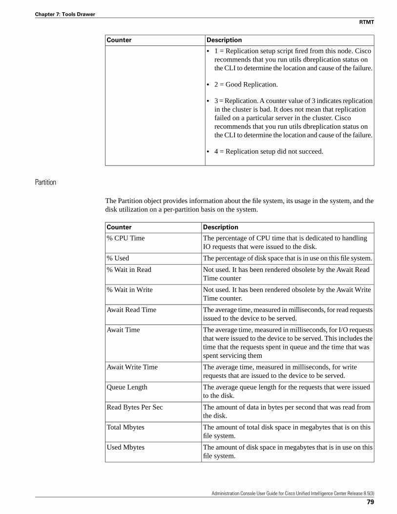
DescriptionCounter
• 1 = Replication setup script fired from this node. Ciscorecommends that you run utils dbreplication status onthe CLI to determine the location and cause of the failure.
• 2 = Good Replication.
• 3 = Replication. A counter value of 3 indicates replicationin the cluster is bad. It does not mean that replicationfailed on a particular server in the cluster. Ciscorecommends that you run utils dbreplication status onthe CLI to determine the location and cause of the failure.
• 4 = Replication setup did not succeed.
Partition
The Partition object provides information about the file system, its usage in the system, and thedisk utilization on a per-partition basis on the system.
DescriptionCounter
The percentage of CPU time that is dedicated to handlingIO requests that were issued to the disk.
% CPU Time
The percentage of disk space that is in use on this file system.% Used
Not used. It has been rendered obsolete by the Await ReadTime counter
% Wait in Read
Not used. It has been rendered obsolete by the Await WriteTime counter.
% Wait in Write
The average time, measured in milliseconds, for read requestsissued to the device to be served.
Await Read Time
The average time, measured in milliseconds, for I/O requeststhat were issued to the device to be served. This includes the
Await Time
time that the requests spent in queue and the time that wasspent servicing them
The average time, measured in milliseconds, for writerequests that are issued to the device to be served.
Await Write Time
The average queue length for the requests that were issuedto the disk.
Queue Length
The amount of data in bytes per second that was read fromthe disk.
Read Bytes Per Sec
The amount of total disk space in megabytes that is on thisfile system.
Total Mbytes
The amount of disk space in megabytes that is in use on thisfile system.
Used Mbytes
Administration Console User Guide for Cisco Unified Intelligence Center Release 8.5(3)
79
Chapter 7: Tools Drawer
RTMT

DescriptionCounter
The amount of data that was written to the disk in bytes persecond.
Write Bytes Per Sec
Process
DescriptionCounter
Expressed as a percentage of total CPU time, represents thetask's share of the elapsed CPU time since the last update.
% CPU Time
The percentage of physical memory that a task is currentlyusing.
% Memory Usage
The stack size for task memory status.Data Stack Size
The nice value of the task. A negative nice value indicates thatthe process has a higher priority. A positive nice value indicates
Nice
that the process has a lower priority. If the nice value equalszero, do not adjust the priority when you are determining thedispatchability of a task.
The number of major page faults that a task encountered thatrequired the data to be loaded into memory.
Page Fault Count
The task's unique process ID, which periodically wraps, thoughnever restarting at zero.
PID
The task's process status: 0 - Running, 1 - Sleeping, 2 -Uninterruptible disk sleep, 3 - Zombie, 4 - Traced or stopped(on a signal), 5 - Paging, 6 - Unknown.
Process Status
The amount of shared memory, in KB, that a task is using.Other processes could potentially share the same memory.
Shared Memory Size
The amount of system time (STime), measured in jiffies, forwhich this process has been scheduled in kernel mode. A jiffy
STime
corresponds to a unit of CPU time and gets used as a base ofmeasurement. One second is equal to 100 jiffies.
The number of threads that are currently grouped with the task.A negative value -1 indicates that this counter is currently not
Thread Count
available because thread statistics (including all performancecounters in the Thread object as well as the Thread Countcounter in the Process object) have been turned off because thesystem's total processes and threads have exceeded the defaultthreshold value.
The total CPU time, measured in jiffies, that the task hasconsumed in user mode and kernel mode since the start of thetask. One second is equal to 100 jiffies.
Total CPU Time Used
The amount of time, measured in jiffies, that the task has beenscheduled for in user mode. One second is equal to 100 jiffies.
UTime
The virtual memory usage of the heap for the task in kilobytes(KB).
VmDate
Administration Console User Guide for Cisco Unified Intelligence Center Release 8.5(3)
80
Chapter 7: Tools Drawer
RTMT

DescriptionCounter
The virtual memory (Vm) resident set size (RSS) that iscurrently in physical memory in kilobytes (KB), includingCode, Data, and Stack.
VmRSS
The total amount of virtual memory, in KB, that the task isusing. It includes all code, data, shared libraries, and pages thathave been swapped out: Virtual I
VmSize
Processor
DescriptionCounter
The processor's share of the elapsed CPU time excluding theidle time since last update, expressed as a percentage of CPUtime.
% CPU Time
The percentage of time that the CPU or CPUs were idle andthe system did not have an outstanding disk I/O request.
Idle Percentage
The percentage of time that the CPU or CPUs were idle,during which the system had an outstanding disk I/O request.
IOwait Percentage
The percentage of time that the processor is executing theinterrupt request which is assigned to devices for interrupt,
Irq Percentage
or sending a signal to the computer when it is finishedprocessing.
The percentage of CPU utilization that occurred whileexecuting at the user level with nice priority.
Nice Percentage
The percentage of time that the processor is executing thesoftirq, which means that task switching is deferred until laterto achieve better performance.
Softirq Percentage
The percentage of CPU utilization that occurred whileexecuting at the system level (kernel).
System Percentage
The percentage of CPU utilization that occurred whileexecuting at the user level (application).
User Percentage
Ramfs
DescriptionCounter
The total number of files in the ram-based filesystem (ramfs).FilesTotal
The amount of free data blocks in the ram-based filesystem(ramfs). A block is a uniformly sized unit of data storage for
SpaceFree
a filesystem. The block size specifies the size that thefilesystem will use to read and write data.
The amount of used data blocks in the ram-based filesystem(ramfs). A block is a uniformly sized unit of data storage for
SpaceUsed
a filesystem. The block size specifies the size that thefilesystem will use to read and write data.
Administration Console User Guide for Cisco Unified Intelligence Center Release 8.5(3)
81
Chapter 7: Tools Drawer
RTMT

Reporting Engine Info
DescriptionCounter
Total number of cells (rows times columns) thathave been retrived from all data sources
Report (H/RT) CellsRetrieved
Change of counter Report (H/RT)CellsRetrieved over the last interval
Report (H/RT) CellsRetrievedInterval
Total number of reports that have beensuccessfully executed
Report (H/RT) Completed
Change of counter Report (H/RT) Completedover the last interval
Report (H/RT) CompletedInterval
Total amount of time spent processing report'sdata to display it in charts.
Report (H/RT) Data PreprocessingTimeChart
Change of counter Report (H/RT)DataPreprocessingTimeChart over the lastinterval.
Report (H/RT) DataPreprocessingTimeChartInterval
Total amount of time spent processing report'sdata to display it in gauges.
Report (H/RT) Data PreprocessingTimeGauge
Change of counter Report (H/RT)DataPreprocessingTimeGauge over the lastinterval.
Report (H/RT) DataPreprocessingTimeGaugeInterval
Total amount of time spent processing report'sdata to display it in grids.
Report (H/RT) Data PreprocessingTimeGrid
Change of counter Report (H/RT)DataPreprocessingTimeGrid over the lastinterval.
Report (H/RT) DataPreprocessingTimeGridInterval
The total number of times that a request to fetcha DataSet has been accepted. Not all requests
Report (H/RT) DataSetFetch Accepted
to fetch a DataSet are accepted. If the data fora report is already being fetched, another workerthread is not created to retrieve the same data.
The interval measure of the above counter.Report (H/RT) DataSetFetch AcceptedInterval
The total number of times that a request to fetchdata from a Data Source has been received.
Report (H/RT) DataSetFetch Requests
This happens every time a report is launchedfor the first time (in which case, there is also arequest to create a new DataSetInfo object), andevery time there is a request to refresh a reportthat has already been launched.
The interval measure of the Report (H/RT)DataSetFetchRequests counter.
Report (H/RT) DataSetFetch RequestsInterval
Out of all the requests for a new DataSetInfoobject (Report (H/RT) DataSetInfoRequested),
Report (H/RT) DataSetInfo Created
Administration Console User Guide for Cisco Unified Intelligence Center Release 8.5(3)
82
Chapter 7: Tools Drawer
RTMT

DescriptionCounter
how many times a new object has actually beencreated.
An object is actually created only when onedoes not already exist for the same ReportDefinition and Filter. This is the case if no userhas ever run that Report Definition with thatFilter or if the Purge mechanism of the CUICDB has cleared up any record of previous usersrunning that Report Definition with that Filter.
The interval measure of the Report (H/RT)DataSetInfoCreated counter.
Report (H/RT) DataSetInfo CreatedInterval
The total number of times that a request tocreate a new DataSetInfo object has beenreceived.
Report (H/RT) DataSetInfo Requested
A new DataSetInfo object is created when areport is being launched for the very first time.By report what is meant is the combination ofa Report Definition and a Filter. For example,executing Report Definition (template) R1 withFilter F1 produces DataSetInfo D1<R1, F1>.Executing Report Definition R2 with Filter F2produce DataSetInfo D2<R2, F2>.
If another user runs Report Definition (template)R1 with Filter F1, a request to create a newDataSetInfo object is received, but a new objectwill not be created. Instead, D1 will be reused.DataSetInfo D1<R1, F1>
The interval measure of the Report (H/RT)DataSetInfoRequested counter.
Report (H/RT) DataSetInfo RequestedInterval
The number of times that a view(grid/gauge/chart) has read the data of a (H/RT)
Report (H/RT) DataSetInfo Read
report. This tells how many times the data ofreports is being prepared to be displayed to auser (turned into HTML or XML).
The interval measurement of the Report (H/RT)DataSetReadTotal counter.
Report (H/RT) DataSetInfo ReadInterval
The total number of reports that have failed.The total number of times that CUIC has tried
Report (H/RT) Failed
to fetch data from a Data Source but it has notbeen able to.
The interval measurement of the Report (H/RT)Failed counter.
Report (H/RT) FailedInterval
Administration Console User Guide for Cisco Unified Intelligence Center Release 8.5(3)
83
Chapter 7: Tools Drawer
RTMT

DescriptionCounter
Total number of times that the data of a reporthas been turned into a Chart and sent to abrowser (or any other client).
Report (H/RT) RenderedChart
The interval measurement of the Report (H/RT)RenderedChart counter.
Report (H/RT) RenderedChart Interval
Total number of times that the data of a reporthas been turned into a Gauge and sent to abrowser (or any other client).
Report (H/RT) RenderedGauge
The interval measurement of the Report (H/RT)RenderedGauge counter.
Report (H/RT) RenderedGauge Interval
Total number of times that the data of a reporthas been turned into a Grid and sent to a browser(or any other client).
Report (H/RT) RenderedGrid
The interval measurement of the Report (H/RT)RenderedGrid counter.
Report (H/RT) RenderedGrid Interval
The total number of rows that have beenretrieved by CUIC from data sources.
Report (H/RT) RenderedRows Retrieved
The interval measurement of the Report (H/RT)RowsRetrievedTotal counter.
Report (H/RT) RenderedRowsRetrievedInterval
The number of (H/RT) reports that are currentlyrunning. A report is currently running when the
Report (H/RT) Running
Runnable object has been assigned a thread fromthe pool. It does not include those that arewaiting in a queue for a thread to becomeavailable.
The interval measurement of the Report (H/RT)Running counter.
Report (H/RT) Running Interval
Total amount of seconds spent running reports.Report (H/RT) Runtime
Change of counter Report (H/RT) Runtime overthe last interval.
Report (H/RT) RuntimeInterval
The number of seconds or milliseconds thatCUIC has spent waiting for ICM, or any other
Report (H/RT) Runtime DatasourceTime
database, to return the data of a query. Thisincludes the time from the moment CUICcommits the JDBC query to the moment CUICgets control back (when the worker thread stopsbeing in an I/O blocked state).
Subset of Report (H/RT) lRuntime. Amount oftime that was spent waiting for data sources toreturn the report's data.
The interval measurement of the Report (H/RT)DataSourceTimeTotal counter.
Report (H/RT) RuntimeDatasourceTimeInterval
Administration Console User Guide for Cisco Unified Intelligence Center Release 8.5(3)
84
Chapter 7: Tools Drawer
RTMT

DescriptionCounter
Total number of reports that are currentlyqueued for execution.
Report (H/RT) Waiting
Change of counter ReportRealtimeWaiting overthe last interval.
Report (H/RT) Waiting Interval
Total number of unique logged in users over thepast interval. Does not count same user wholeaves and comes back within the interval.
ReportsUniqueUsersLoggedinInterval
Total number of failed login attempts.ReportsUsersFailedLoginAttempts
Change of counterReportsUsersFailedLoginAttempts over the lastinterval.
ReportsUsersFailedLoginAttemptsInterval
Total number of users that are currently loggedin
ReportsUsersLoggedin
SchedulerInfo
DescriptionCounter
How often the scheduler will execute, in seconds.SchedulerIntervalLength
The number of jobs that the scheduler service has completedSchedulerJobsCompletedCount
The number of jobs that the scheduler service has failed tocomplete successfully.
SchedulerJobsFailedCount
The number of jobs that the scheduler service is currentlyrunning.
SchedulerJobsRunningCount
The current state of the scheduler. The possible values are: 0.- Stopped, 1.- Idle, 2.- Suspended and 3.-Running
SchedulerState
System
The System object provides information for file descriptors (FD), total processes and threads,total CPU time measured on the system.
DescriptionCounter
Represents the total number of allocated file descriptors.Allocated FDs
Represents the number of file descriptors that is currentlyin use in the system.
Being Used FDs
Represents the total number of allocated file descriptors onthe system that is freed.
Freed Fds
The average time, in milliseconds, for I/O requests issuedto all devices to be served. This includes the time spent by
IOAwait
the requests in queue and the time spent servicing therequests.
Administration Console User Guide for Cisco Unified Intelligence Center Release 8.5(3)
85
Chapter 7: Tools Drawer
RTMT

DescriptionCounter
The percentage of CPU time during which I/O requestswere issued to the device (bandwidth utilization for thedevice) on this server.
IOCpuUtil
The average queue length of the requests that were issuedto all devices on this server.
IODeviceReqQueueSize
The average size in sectors of the requests that were issuedto all devices on this server.
IODeviceReqSectorSize
The total number of KBytes read per second from alldevices on this server.
IOKBytesReadPerSecond
The total number of KBytes written per second to all deviceson this server.
IOKBytesWrittenPerSecond
The total number of input/output operations on all diskpartitions per second on this server. If you experience a
IOPerSecond
system performance issue, use the information in thiscounter to measure the impact of the aggregate I/Ooperations on this server.
The total number of read requests per second that wereissued to all devices on this server.
IOReadReqPerSecond
The total number of read requests merged per second thatwere queued to all devices on this server.
IOReadQueueMergedPerSecond
The total number of sectors read per second from all deviceson this server.
IOSectorsReadPerSecond
The total number of sectors written per second to all deviceson this server.
IOSectorsWrittenPerSecond
The average service time, in milliseconds, for I/O requeststhat were issued to all devices on this server.
IOServiceTime
The total number of write requests per second that wereissued to all devices on this server.
IOWriteReqPerSecond
The total number of write requests merged per second thatwere queued to all devices on this server.
IOWriteReqQueueMergedPerSecond
Represents the maximum number of file descriptors that isallowed on the system.
Max Fds
Represents the total time, measured in jiffies, that the systemhas been up and running. A jiffy corresponds to a unit of
Total CPU Time
CPU time and gets used as a base of measurement. Onesecond is equal to 100 jiffies.
Represents the total number of processes on the system.Total Processes
Represents the total number of threads on the system.Total Threads
Administration Console User Guide for Cisco Unified Intelligence Center Release 8.5(3)
86
Chapter 7: Tools Drawer
RTMT

TCP
DescriptionCounter
The number of times that TCP connections have made a directtransition to the SYN-SENT state from the CLOSED state.
Active Opens
The number of times that TCP connections have made a directtransition to the CLOSED stated from either the SYN-RCVD
Attempt Fails
state or the SYN-RCVD state, plus the number of times TCPconnections have made a direct transition to the LISTEN statefrom the SYS-RCVD state.
The number of TCP connections for which the current state iseither ESTABLISHED or CLOSE-WAIT.
Curr Estab
The number of times that the TCP connections have made adirect transition to the CLOSED state from either theESTABLISHED state or the CLOSE-WAIT state.
Estab Resets
The total number of segments received, including those receivedin error. This count includes segments received on currentlyestablished connections.
In Segs
The total number of segments that were sent and the totalnumber of segments that were received.
InOut Segs
The total number of segments sent, including those on currentconnections but excluding those containing only retransmittedoctects.
Out Segs
The number of times that TCP connections have made a directtransition to the SYN-RCVD state from the LISTEN state.
Passive Opens
The total number of segments retransmitted, that is, the numberof TCP segments transmitted containing one or more previouslytransmitted octets.
RetransSegs
Thread
DescriptionCounter
The thread's share of the elapsed CPU time since the last update,expressed as a percentage of total CPU time.
% CPU Time
The thread's leader process ID.PID
Administration Console User Guide for Cisco Unified Intelligence Center Release 8.5(3)
87
Chapter 7: Tools Drawer
RTMT

Administration Console User Guide for Cisco Unified Intelligence Center Release 8.5(3)
88
Chapter 7: Tools Drawer
RTMT

The Administration Console InterfaceThis chapter contains the following topics:
• Drawers, page 89• Filter, page 90• Online Help, page 90• Sorting, page 90• Title Bar, page 91• Licenses, page 91• Users in the Administration Console, page 93
Drawers
The left panel of the Administration interface contains drawers.
Drawers are similar to menus: they group logically-related functions. Clicking (opening) adrawer in the left panel might immediately open a page in the right panel or it might expand toshow a list or tree of nested links.
Figure 15: Drawers in the Administration Console
Administration Console User Guide for Cisco Unified Intelligence Center Release 8.5(3)
89
Chapter 8

Filter
Many pages let you filter items to limit the number of results that appear in a given list. Youcan also filter items to find a specific item or a subset of items with similar values.
Note: Quickly clear a filter by clicking the Clear Filter button.
Online Help
There is a Help icon on each page.
Clicking Help opens a new window with a topic relevant to the window you are on.
From a help topic, click the Navigation icon
Figure 16: Online Help Navigation Icon
This opens the Table of Contents and exposes the help functions such as Index and Search.
Figure 17: Online Help
Sorting
Any page that contains lists of items can be sorted by any field name. To sort a list of items:
Step 1 Click the name of the field on the top of the column that you want to sort.
The listed is sorted in ascending order for that column.
Step 2 Click the name of the field again to sort the list in descending order.
Administration Console User Guide for Cisco Unified Intelligence Center Release 8.5(3)
90
Chapter 8: The Administration Console Interface
Filter

Step 3 Click any other field name at the top of the column to sort on that column.
Title Bar
The title bar is visible from each window and has the following:
• A Cisco Systems logo that links to http://www.cisco.com/.
• A Navigation dropdown, where you can open Disaster Recovery System, Cisco Unified OSAdministration, and Cisco Unified Serviceability.
• A Log Out link.
• The About link.
Licenses
Unified IC licenses are "node-locked." This means a license is physically located on the Controllernode and is distributed to all members nodes in the cluster through database replication.
There can be only one license installed on a system at any point in time.
Uploading the license file is the first action the Super User must take after installing the Controllernode.
After installation, until the Super User obtains and uploads a Standard or Premium license, heor she:
• Can sign in to the Operations Console to view the Controller and to add the alias name.
• Cannot perform other Operations Console functions.
• Cannot sign in to the Unified IC Reporting application.
• Cannot install member nodes.
How To Obtain Your License
To acquire a license:
1. Go to the Cisco Product License Registration website at this URL: https://tools.cisco.com/SWIFT/Licensing/PrivateRegistrationServlet
2. If you do not have a PAK, click the available licenses link (https://tools.cisco.com/SWIFT/Licensing/PrivateRegistrationServlet?DemoKeys=Y).
Administration Console User Guide for Cisco Unified Intelligence Center Release 8.5(3)
91
Chapter 8: The Administration Console Interface
Title Bar

3. Scroll to Voice Products and click Cisco Unified Intelligence Center - v8.0.
4. Enter your MACAddress, accept the agreement, and enter your Registrant Information.
5. Follow prompts to complete the registration pages.
You will receive the license file in an email from Cisco Systems. When you receive it, save itlocally in a location where it cannot be deleted by mistake or opened by an unauthorized person.In the event that your system becomes corrupted, you can browse to this location to upload thelicense file again.
The same license file will be valid if you need to reapply it - unless you apply it to a new serverwith a new MAC address.
Caution: License files are human-readable and can be opened. However, changing anytext in the license file invalidates the license.
License Types
Unified Intelligence Suite has four license types: Demo, Lab/Trial, Standard, and Premium.
FEATURESUSERSNODESEXPIRATIONTYPE
Premium feature setNo limitController and allMember nodes (amaximum of 8 nodes).
Valid for 90 days andcontains an expirationdate.
DEMO
Can be extended forone additional 90-daysession with areinstallation ofUnified IC.
Premium feature setFive usersController node onlyHas noexpiration/timeout.
LAB/TRIAL
Standard feature setUnlimited but requiressystem sizing for
Controller and allMember nodes (amaximum of 8 nodes).
Has noexpiration/timeout.
STANDARD
optimum performance.See the Sizing Tool forguidelines.
Premium feature setUnlimited but requiressystem sizing for
Controller and allMember nodes (amaximum of 8 nodes).
Has noexpiration/timeout.
PREMIUM
optimum performance.See the Sizing Tool forguidelines.
Administration Console User Guide for Cisco Unified Intelligence Center Release 8.5(3)
92
Chapter 8: The Administration Console Interface
Licenses

Users in the Administration Console
There are three user accounts that have access to the Administration console:
• Super Users (page 93)
• System Application User (page 93)
• System Administration User (page 94)
Super Users
This user role is defined in the Administration console. It is the only user role for Administration.
The initial and default Super User is the System Application User (page 93) who is configuredduring installation.
The initial Super User (the System Appplication User) can sign in to the Unified IC Reportingconsole and has all User Roles and full permissions for all drawers in Unified IC Reporting.Those credentials cannot be removed from the initial Super User.
Additional Super Users who are added in the Administration Console can also sign in to UnifiedIC Reporting and are considered to be IMS users. They have the limited Login User role onlyuntil the Unified IC Reporting security administrator gives them additional roles and flags themas Active users.
System Application User
This user role is defined during installation. Although it is possible to define unique applicationuser names and passwords during the installation of each node, it is a best practice to use thesame credentials for all installations.
The application user defined during the installation of the Controller is the only SystemApplication User recognized by Unified IC.
This user has full rights to all functions in the Administration and Unified IC reportingapplications, as described below:
• Can log in to the Adminstration application and becomes the initial Super User forAdministation.
• Can create additional Super Users in the Administration application.
• Can sign in to Unified IC and has full rights to all functions in Unified IC.
• Is the initial Security Administrator user in the Unified IC reporting application
Administration Console User Guide for Cisco Unified Intelligence Center Release 8.5(3)
93
Chapter 8: The Administration Console Interface
Users in the Administration Console

• Can create additional Security Administrator users in the Unified IC reporting application.
• Cannot have any role taken away from him.
• Cannot take any role away from himself.
• This user can log in to the Reporting application and is the intial System
System Administration User
The System Administrator account User ID and password are configured at installation for eachnode. It is a best practice to enter the same user name and password for all nodes.
The System Administrator for the Controller can access:
• The Cisco Systems tools on the Navigation dropdown in the Administration console: DisasterRecovery System, Cisco Unified Serviceability, and Cisco Unified OS Administrationinterfaces.
• The CLI for the Controller.
The System Administrator has no access to functions in the Unified IC reporting application.
Note: If you configure unique System Administrator credentials for Member nodes, use thosecredentials to access the CLI for those Member servers.
Administration Console User Guide for Cisco Unified Intelligence Center Release 8.5(3)
94
Chapter 8: The Administration Console Interface
Users in the Administration Console

Command Line InterfaceThe Command Line Interface (CLI) provides a set of commands applicable to the operatingsystem, to the Unified Intelligence Center database (cuic_data) and to the system database(ccm_<version>).
These commands allow basic maintenance and failure recovery and also enable some systemadministration when the Cisco Unified IC operations console is unavailable.
You can access the CLI directly, using the monitor and keyboard at the server console:
1. Enter the ID for the System Administration user (the one created during install).
2. When prompted, enter the password for the System Administration user.
In addition to the CLI commands listed in this chapter, you can also enter:
• help - to display the list of all supported commands. For example, to display help for a specificcommand, type help delete dns and press Enter.
• quit to close the CLI.
In the command syntax descriptions:
bold is used for the base command.
italics are used for mandatory parameters, when the syntax includes them.
[ ] brackets are used for options, when the syntax includes them.
Administration Console User Guide for Cisco Unified Intelligence Center Release 8.5(3)
95
Appendix A

Using CLI
Certain CLI commands are useful for specific inquiries.
Basic system commands:
• utils system restart (page 153)
• utils system shutdown (page 153)
• utils system switch-version (page 154)
• utils system upgrade (page 154)
• set network (page 109) (dns / dhcp / hostname / mtu / cluster
• set password (page 113)
• show status (page 130)
Disk and Backup:
• utils disaster recovery_backup (page 143)
• utils disk raid maintenance (page 150)
• show diskusage (page 121)
Hardware Information:
• show hardware (page 121)
• show memory (page 122)
• show ups staus (page 137)
• show environment (page 121)
• utils create report hardware (page 140)
• show tech system (page 135)
Performance:
• show status (page 130)
• show process using-most cpu/memory (page 129)
Administration Console User Guide for Cisco Unified Intelligence Center Release 8.5(3)
96
Command Line Interface
Using CLI

• shows stats io (page 130)
• utils iostat (page 146)
• show perf (page 126)
• utils service start (page 151)
Platform:
• show process list (page 128)
• show open files (page 124)
• show open ports (page 125)
• show timezone (page 136)
• utils core analyze (page 140)
• utils create report platform (page 140)
• show version (page 137)
Network Utilities:
• set network (page 109)
• utils network ping (page 148)
• utils firewall (page 145)
• show tech network (page 133)
Security
• set account (page 105)
• show logins (page 122)
• show web-security (page 137)
• show cert list (page 119)
• utils auditd (page 139)
• utils csa (page 140)
• utils firewall (page 145)
Administration Console User Guide for Cisco Unified Intelligence Center Release 8.5(3)
97
Command Line Interface
Using CLI
Unified IC:
• show packages active cuic (page 125)
• show cuic properties (page 119)
• set cuic properties (page 107)
• show cuic-license-info (page 120)
• set trace (page 115)
• show trace (page 136)
• show perf (page 126)
Unified IC Database:
• run sql (page 104)
• show tech (page 131)
• utils dbreplication (page 141)
Delete Commands
• delete account (page 98)
• delete dns (page 99)
• delete ipsec (page 99)
• delete process (page 99)
• delete smtp (page 99)
delete account
This command allows you to delete an administrator account.
COMMAND: delete account name
PARAMETER name specifies the name of the admin account.
Administration Console User Guide for Cisco Unified Intelligence Center Release 8.5(3)
98
Command Line Interface
Delete Commands

delete dns
This command deletes the specified DNS server from the system and results in loss of networkconnectivity.
COMMAND: delete dns addr
PARAMETER addr specifies the IP address name of the domain name server.
delete ipsec
These commands allow you to delete IPSec policies. You can delete a pokcy with a given policyname and group.
COMMANDS:
delete ipsec policy_group [group | all] Use to delete all policies within a group or to deleteall groups.
delete ipsec policy_name [policy_group] [policy_name] Use to delete a policy with a givenpolicy name and group. Example:delete ipsec policy_name group1 name1
PARAMETERS:
policy_group
policy_name
delete process
This command allows you to delete a particular process.
COMMAND: delete process pid [options]
PARAMETER pid specifies the process ID number.
OPTIONS:
[force] stops the process.
[terminate] terminates the process.
[crash] crashes the process with a crash dump.
delete smtp
This command deletes the SMTP host.
Administration Console User Guide for Cisco Unified Intelligence Center Release 8.5(3)
99
Command Line Interface
Delete Commands

COMMAND: delete smtp
File Commands
• file check (page 100)
• file delete (page 100)
• file dump (page 101)
• file get (page 101)
• file list (page 102)
• file search (page 102)
• file tail (page 103)
• file view (page 103)
file check
This command checks whether any files or directories have been added, removed, or changedin size since the last fresh installation or upgrade. The results display after the check.
Note: This command is system-intensive. Run it at off-hours.
COMMAND: file check [detection-size-kb]
OPTION: [detection-size-kb] specifies the minimum file size change that is required for thecommand to display the file as changed. The default is 100Kb.
file delete
These commands delete one or more specified files.
COMMANDS:
file delete activelog file-spec [options]
file delete inactivelog file-spec [options]
file delete install file-spec [options]
file delete license file-name [options]
PARAMETERS:
Administration Console User Guide for Cisco Unified Intelligence Center Release 8.5(3)
100
Command Line Interface
File Commands

file-spec specifies the path and filename of the file(s) to delete.
file-name specifies the name of the license file to delete.
OPTIONS:
[detail] displays a listing of deleted files with the date and time.
[noconfirm] deletes files without asking you to confirm each deletion.
Caution: You cannot recover a deleted file, except possibly by using the Disaster RecoverySystem.
file dump
These commands dump the contents of the indicated files to the screen, one page at a time.
COMMANDS:
file dump activelog file-spec [options]
file dump inactivelog file-spec [options]
file dump install file-spec [options]
file dump sftpdetails file-spec [options]
PARAMETER file-spec specifies the path and filename of the file(s) to dump.
OPTIONS:
[detail] displays listing with the date and time.
[hex] displays output in hexadecimal.
file get
These commands get (transfer) the specified file to another system by using SFTP. After thecommand identifies the specified files, you are prompted to enter an SFTP host, username, andpassword.
COMMANDS:
file get activelog file-spec [options]
file get inactivelog file-spec [options]
file get install file-spec [options]
file get partBsalog file-spec [options]
Administration Console User Guide for Cisco Unified Intelligence Center Release 8.5(3)
101
Command Line Interface
File Commands

file get salog file-spec [options]
PARAMETER file-spec specifies the path and filename of the file(s) to transfer.
OPTIONS:
[abstime] is absolute time period, specified as hh:mm:MM/DD/YY.
[reltime] is relative time period, specified as minutes | hours | days | weeks | months value.
[match] matches a particular string in the filename, specified as string value.
[recurs] gets all files, including subdirectories.
file list
These commands list the log files in an available log directory.
COMMANDS:
file list activelog file-spec [options]
file list inactivelog file-spec [options]
file list install file-spec [options]
file list partBsalog file-spec[options]
file list salog file-spec [options]
file list sftpdetails file-spec [options]
PARAMETER file-spec specifies the path to the directory to list.
OPTIONS:
[page] displays the output one screen at a time.
[reverse] reverses sort direction.
[detail] displays a long listing with date and time.
[date] sorts by date.
[size] sorts by file size.
file search
These commands search the content of a log and display the matching lines one page at a time.
COMMANDS:
Administration Console User Guide for Cisco Unified Intelligence Center Release 8.5(3)
102
Command Line Interface
File Commands

file search activelog file-spec [options]
file search inactivelog file-spec [options]
file search install file-spec [options]
PARAMETERS:
file-spec represents the path to the file(s) to search.
reg-exp represents a regular expression.
OPTIONS:
[reltime] only search files that were modified within relative time.
[abstime] only search files that were modified within specific time range.
[ignorecase] ignores case distinctions.
[recurs] searches for the pattern recursively through subdirectories.
file tail
These commands tail (print the last few lines) of a log file.
COMMANDS:
file tail activelog file-spec [options]
file tail inactivelog file-spec [options]
file tail install file-spec [options]
PARAMETER file-spec specifies the path to the file to tail.
OPTIONS:
[detail] displays a long listing with date and time.
[hex] displays hexadecimal listing.
[lines] specifies number of lines to display.
file view
These commands display the contents of the logging files specified.
COMMANDS:
file view activelog file-spec
Administration Console User Guide for Cisco Unified Intelligence Center Release 8.5(3)
103
Command Line Interface
File Commands

file view inactivelog file-spec
file view install file-spec
file view system-management-log
PARAMETER file-spec specifies the path to the file to view.
Run Commands
• run loadxml (page 104)
• run sql (page 104)
run loadxml
This command can be run on the publisher (the Controller node) as a workaround when serviceparameters or product specific information does not appear on the administration screen.
Running this command might necessitate a restart of some services.
COMMAND: run loadxml
run sql
This runs a SQL command to query and select from the database and table.
COMMAND: run sql sql statement [options]
PARAMETER sql statement specifies the SQL command to run. For example, select * fromtablename.
OPTIONS:
[ccm] - operating system database. This is the default. If you do not include the cuic option,this command runs a sql statement from the system database.
[cuic] - Unified IC database. For example, select * from cuic:tablename
You can run only one sql_statement at a time. But in the sql_statement you can use multipletables. For example: Select * from cuic:cuicreport, cuic_data:cuicreportdefinition.
Set Commands
• set account (page 105)
Administration Console User Guide for Cisco Unified Intelligence Center Release 8.5(3)
104
Command Line Interface
Run Commands

• set accountlocking (page 105)
• set cert (page 106)
• set cli (page 106)
• set commandcount (page 106)
• set cuic-properties (page 107)
• set ipsec (page 108)
• set logging (page 109)
• set network (page 109)
• set password (page 113)
• set smtp (page 115)
• set syslog (page 115)
• set timezone (page 115)
• set trace (page 115)
• set web-security (page 117)
• set workingdir (page 117)
set account
COMMANDS:
set account name
This command sets up a new account and prompts for privilege level and password.
PARAMETER name specifies the name of the admin account.
set account enable
Use this command to enable the user account if the account is disabled due to password inactivity.
set accountlocking
Use these commands to control the admistrator accounts.
COMMAND: set accountlocking enable | disable | unlocktime
Administration Console User Guide for Cisco Unified Intelligence Center Release 8.5(3)
105
Command Line Interface
Set Commands

PARAMETER enable enables account locking.
PARAMETER disable disables account locking.
PARAMETER unlocktime Use this command to configure the unlock time for admin accountsin seconds. Acceptable values are equal to or greater than 300 seconds but less than 3600 seconds(60 mins).
set cert
This command regenerates the certificate for the unit name. See also show cert (page 119).
COMMANDS:
set cert bulk unit | all This command consolidates all the certificates available for this unit inthe pre-configured sftp location and exports the consolidated file to the same sftp location.
set cert export unit | allThis command consolidates all the certificates available for this unitin the pre-configured sftp location and exports the consolidated file to the same sftp location.
set cert import unit | allThis command consolidates all the certificates available for this unitin the pre-configured sftp location and imports the consolidated file to the same sftp location.
set cert regen unit name This command regenerates the certificate for the unit name and promptfor a restart to activate the regenerated certificate.
set cert sftp This command prompts for the SFTP IP address, server port, User ID, password,and remote directory information to be used for Bulk operations.
PARAMETERS:
unit and unit name specifies the name of the unit.
set cli
Run this command to set the paginiation of the current CLI session.
COMMAND: set cli pagination name
PARAMETER on or off
set commandcount
These commands change the CLI command prompt, so it displays or hides the number of CLIcommands executed in the current session.
COMMANDS:
set commandcount enable
Administration Console User Guide for Cisco Unified Intelligence Center Release 8.5(3)
106
Command Line Interface
Set Commands

set commandcount disable
set cuic-properties
Use these commands to set values for the cuic database and session timeout.
COMMANDS:
set cuic-properties host-to-ip
PARAMETER <host> <ip-address>
This command sets the host-to-ip translation and is used when there is a need to configure andIP address for one of the UCCE Databases that is unique to the member node from which youare running the command. This command allows for scalability and overrides the defaultHistorical or Realtime database server that is defined in the Data Sources interface.
For <host>, enter the value for the host DNS name for the server, as displayed on the DataSources interface.
For <ip-address>, enter the IP address of the server for the Historical or Realtime database.
set cuic-properties purge-time
PARAMETER 1<HH:MM > <AM/PM>
PARAMETER 2 <Interval (in minutes)>
This command sets the time of day when the CUIC database will be purged and the duration(in minutes) after which the purge operation should be rerun. The default purge time is 12:00AM and the default purge interval is 60 minutes.
For <HH:MM> and <AM/PM> specify the time of the day when you want the purge job to runfor the first time.
For <Interval (in minutes)>, specify the interval in minutes after which you want the purge jobto rerun.
After you run this command with the correct parameters, the system displays a message asfollows:
Next purge is scheduled to run after <x> hours <y> minutes.Value has been successfully set.
Following are the various category of data that the system purges when you use these CLIcommands:
1. Cached report data - Data in this category is purged based on the time specified usingthe set cuic-properties purge-time command. Note that the purge time iscalculated based on the time when the filter used to run the report was last used or refreshed.
Administration Console User Guide for Cisco Unified Intelligence Center Release 8.5(3)
107
Command Line Interface
Set Commands
2. Audit trail - All audit trail data that is older than a month are purged during the last purgeoperation of the day.
3. Cached scheduled report data - The set cuic-properties purge-retentionCLI command applies only to this category.
Each rerun that the system performs using this command, results in the purging of the cachedreport data. Other categories are purged only during the last purge run of the day.
If you restart the CUIC server after the purge start time, the system discontinues the currentpurge cycle till the same purge start time on the next day.
For example, if you have set to run the purge job at 11.45 AM on a day with a rerun interval ofone hour and the CUIC server was restarted at 2 PM, the following happens with respect to thepurge runs and reruns:
• purge job runs normally at 11.45 AM, 12.45 PM, and 1.45 PM.
• After the restart at 2 PM, the system checks for the purge start time and since the purge starttime is set as 11.45 AM, the next purge run happens only at 11.45 AM on the next day.
To have continuous rerun even after the system restarts, you must set the pruge start time andinterval again using the set cuic-properties purge-time CLI command.
set cuic-properties purge-retention
PARAMETER #number of days
This command sets the number of day(s) that data in the cuic database is retained before it getspurged. The default is one day and the maximum permissible value is 31 days.
Note: Cached scheduled report data - The set cuic-properties purge-retention CLIcommand applies only to this category.
set cuic-properties session-timeout
PARAMETER #numberofSeconds
This command sets the Session Timeout for the Unified IC Reporting web application. Thedefault is 14,400 seconds (4 hours).
set ipsec
Use these commands to enable ipsec policies.
COMMAND: set ipsec policy_group [group | all] Use to enable all policies within a group orall groups.
COMMAND: set ipsec policy_name [policy_group] [policy_name] Use to enable a policywith a given policy name and group. Example:set ipsec policy_name group1 name1
Administration Console User Guide for Cisco Unified Intelligence Center Release 8.5(3)
108
Command Line Interface
Set Commands

set logging
These commands allow you to enable or disable logging.
COMMANDS:
set logging enable
set logging disable
set network
set network cluster publisher
Caution: These commands are not supported for Unified IC.
set network cluster publisher hostname This command configures the cluster publisherhostname and cause a temporary loss of network connectivity whil the network is restarted withthe new configuration.
set network cluster publisher ip This command configures the cluster publisher ip addressand cause a temporary loss of network connectivity whil the network is restarted with the newconfiguration.
set network dhcp eth0
These commands set the ethernet interface to disable dhcp (if enabled) or to use dhcp (if notalready enabled). Entering this command prompts for verification and, if executed, causes thesystem to restart.
COMMANDS:
set network dhcp eth0 enable
set network dhcp eth0 disable
set network dns options
This command allows you to set the dns options.
COMMAND: set network dns options [options]
OPTIONS:
[timeout xx] sets the DNS request timeout in seconds.
[attempts xx] sets the number of times to attempt a DNS request before quitting.
Administration Console User Guide for Cisco Unified Intelligence Center Release 8.5(3)
109
Command Line Interface
Set Commands

[rotate] causes the system to rotate among the configured DNS servers, distributing the load.
set network dns {primary | secondary}
These commands set the IP address for the primary or secondary DNS server. Entering thiscommand prompts for verification and, if executed, causes a loss of network connectivity.
COMMANDS:
set network dns primary addr
set network dns secondary addr
PARAMETER addr specifies the address of the server.
set network domain
This command sets the domain name for the system. Entering this command prompts forverification and, if executed, causes a loss of network connectivity.
COMMAND: set network domain name
PARAMETER name specifies the name of the domain.
set network failover
These commands enable and disable Network Fault Tolerance on the Media Convergence Servernetwork interface card. Entering the command prompts for verification and, if executed, causesthe system to restart.
COMMANDS:
set network failover ena op
set network failover dis op
PARAMETER op indicates the operation.
set network gateway
This command enables you to configure the IP address of the network gateway. Entering thiscommand prompts for verification and, if executed, causes the system to restart.
COMMAND: set network gateway addr
PARAMETER addr specifies the address of the gateway.
Administration Console User Guide for Cisco Unified Intelligence Center Release 8.5(3)
110
Command Line Interface
Set Commands

set network hostname
This command sets the netwrok hostname and then causes a restart of the system The hostnamemust follow the rules for ARPANET host names. The hostname must start with an alphabet,end with an alphanumeric, and may contrain any alphanumeric characters or hyphen in between.The hostname must be 63 characters or less.
COMMAND: set network hostename [name] addr
PARAMETER name specifies the network hostname.
set network ip eth0
Caution: This command is not supported for Unified IC.
This command sets the IP address for Ethernet interface 0.
The system asks whether you want to continue to execute this command. If you continue, thiscommand causes the system to restart.
COMMAND: set network ip eth0 <addr> <mask>
PARAMETERS:
addr is the IP address.
mask is the mask.
set network ipv6
These commands are used for configuring the IPv6 feature on the machine.
COMMANDS:
set network ip dhcp action reboot This command is used for enabling or disabling the DHCPv6client.
set network ip service action reboot reboot This command is used for enabling or disablingthe IPv6 feature client.
set network ipv6 static_address addr mask This command is used for setting the static IPv6address on the the server.
PARAMETERS:
Action is mandatory can can have either of these values: {enable | disable
mask is the mask.
Reboot. Reboot after making these changes.
Administration Console User Guide for Cisco Unified Intelligence Center Release 8.5(3)
111
Command Line Interface
Set Commands

addr is the IP address.
mask is the mask.
set network max_ip_conntrack
This command sets the maximum value for ip_conntract_max.
COMMAND: set network max_ip_conntrack ip_conntrack_max
PARAMETER ip_conntrack_max indicates the maximum value
set network mtu
This command sets the maximum MTU value. The valid range is 500-1500.
COMMAND: set network mtu size
PARAMETER size must be 1500 for all servers in the cluster.
set network nic eth0
This command sets the properties of the Ethernet Interface 0. It asks if you want to continue. Ifyou continue, this command causes a temporary loss of network connections while the NIC isreset.
COMMAND: set network nic etho0 auto [en | dis] speed [10 | 100] duplex [half | full]
PARAMETERS: At least one is mandatory. Each parameter takes options indicated.
auto specifies whether auto negotiation gets enabled or disabled.
speed specifies the speed of the Ethernet connection: 10 or 100 Mbps.
duplex specifies half-duplex or full-duplex.
set network pmtud
This command enables or disables Path MTU Discovery.
The system asks whether you want to continue to execute this command. If you continue, thesystem temporarily loses network connectivity.
COMMAND: set network pmtud state {enable | disable}
PARAMETER state {enable | disable}
Administration Console User Guide for Cisco Unified Intelligence Center Release 8.5(3)
112
Command Line Interface
Set Commands

set network restore
This command restarts the networking on this host. If confirmed, this command causes atemporary loss of network connectivity.
Caution: Only use this command when all other CLI 'set network ...' commands havefailed to restore network connectivity to an Ethernet port. This command removes allprevious Ethernet and Network Fault Tolerance settings. The specified Ethernet port isconfigured with a minimal static IP address configuration. It is imperative that the originalEthernet port settings be reconfigured AFTER this command using other CLI 'set network...' commands.
COMMAND: set network restore <ethernet port> <ip-address> <network-mask> <gateway>
PARAMETERS:
ethernet-port is the Ethernet port (for example, eth0).
ip-address is the IP address of the host.
network-mask is the network mask.
gateway is the Gateway IP address.
set network status eth0
This command sets the state of the ethernet interface eth0 to up or down.
Caution: Only use this command when all other CLI 'set network ...' commands havefailed to restore network connectivity to an Ethernet port. This command erases all previousEthernet and Network Fault Tolerance settings. The specified Ethernet port is configuredwith a minimal static IP address configuration. It's imperative that the original Ethernetport settings be reconfigured AFTER this command using other CLI 'set network ...'commands.
COMMAND: set network status eth0 state {up | down}
PARAMETER state {up | down} to set the status up or down is required.
set password
Use these commands to configure password rules.
COMMANDS:
set password age maximum | days minimum | days
set password complexity character minimum-length
Administration Console User Guide for Cisco Unified Intelligence Center Release 8.5(3)
113
Command Line Interface
Set Commands

Use this commands to enable or disable password complexity rules.
set password expiry maximum-age minimum-age
set password history number
set password inactivity enable | disable |period (days)
Use these commands to enable the operating system password inactivity to the default value of10 days, to disable password inactivity, or set the number of days.
set password user admin security
These commands allow you to change the system administrator and security passwords.
The system prompts you for the old and new passwords and checks the password for strength.
PARAMETERS:
character takes {enable | disable}
When enabled, passwords need to meet these guidelines:
• have at least one lower-case character
• have at least one uppercase, one digit and one special character.
• contain no characters that are adjacent on the keyboard
• have not been used as any of the previous ten passwords. 5. The admin user password canonly be changed only once in 24 hours.
• cannot have been changed in the past 24 hours.
minimum-length
When enabled, modify the value of minimum password length for CUCM OS accounts.Acceptable values should be equal to or greater than 6. Use this command only after enablingthe character complexity of passwords.
maximum days Use this command to set the value of the maximum age for the admin accountsin days. Acceptable values should be equal to or greater than 10 days but less than 3650 days(10 years).
minimum days Use this command to set the minimum password age for the admin accounts indays.
maximum-age takes {enable | disable)
Enabling the maximum age sets the value of maximum password age to 3650 days (10 yrs) forCUCM OS admin accounts.
Administration Console User Guide for Cisco Unified Intelligence Center Release 8.5(3)
114
Command Line Interface
Set Commands
minimum-age takes {enable | disable)
number The number of passwords to maintain in history. Default is 10. Maximum is 20. Enter0 to disable.
admin Sets the admin password.
security Sets the security password.
set smtp
This command sets the SMTP server hostname.
COMMAND: set smtp host
PARAMETER host indicates the hostname for the smtp server.
set syslog
This command set the syslog as enabled or disabled.
COMMAND: set syslog enable | disable
set timezone
This command changes or sets the timezone. You must restart the system after you change thetimezone.
COMMAND: set timezone zone
PARAMETER zone indicates the timezone.
Enter the appropriate string or zone index id to uniquely identify the timezone.
To see a list of valid timezones, use the show timezone (page 136) command.
Be aware that the timezone name is case-sensitive.
set trace
Use these commands to set or change the log levels and trace setting for the subsystems of twoserver processes (cuicserver and oampserver) to basic or detailed.
COMMAND:
set trace basiccuicserver [subsystem] none
set trace basicoampserver [subsystem] none
Administration Console User Guide for Cisco Unified Intelligence Center Release 8.5(3)
115
Command Line Interface
Set Commands

set trace infrastructurecuicserver [subsystem] [TRACE_FLAGS | none]
set trace infrastructureoampserver [subsystem] [TRACE_FLAGS | none]
set trace subsystem cuicserver [subsystem] [trace_mask1 trace_mask2]
set trace subsystem oampserver [subsystem] [trace_mask1 trace_mask2]
For cuicserver, the valid subsystems are:
• Infrastructure
• CUIC
• CUIC_MODEL_OBJECTS
• CUIC_DATA_PROCESSING
• CUIC_SECURITY
• CUIC_DISPLAY
• CUIC_MIGRATION
• CUIC_USER_HISTORY
• CUIC_JSP
• CUIC_STATISTICS
For oampserver, the valid subsystems are:
• Infrastructure
• OAMP_BO
• OAMP
• WSM_BO
Detailed log levels are set by enabling trace flags. which allows debug statements to appear inthe logs. You can control debug tracing for specific functionalities (specified in the TRACEflag name), within specific subsystem components. See Infrastructure Trace Definitions (page23).
basic indicates to set a basic level of tracing. With this setting, messages and warnings aredisplayed.
detailed indicates to set a debug level and allows you to turn on tracing for specific components.
subsystem indicates the subsytem you are setting and displays the list of all valid subsystems.
Administration Console User Guide for Cisco Unified Intelligence Center Release 8.5(3)
116
Command Line Interface
Set Commands

none inidicates that you do not want to set a flag for tracing
set web-security
This command sets the web security certificate information for the operating system.
COMMAND: set web-security <orgunit> <orgname> <locality> <state> < country>
PARAMETERS: (All five are mandatory.)
orgunit is the organizational unit.
orgname is the organizational name.
locality is the location of the organization.
state is the state of the organization.
country is the country of the organization.
set workingdir
These commands set the CLI working directory for activelog or inactivelog.
COMMANDS:
set workingdir activelog directory
set workingdir inactivelog directory
PARAMETER directory must be a valid sub-directory of the activelog or inactivelog.
Show Commands
• show account (page 118)
• show accountlocking (page 119)
• show cert (page 119)
• show cli (page 119)
• show cuic-properties (page 119)
• show cuis-component-status (page 120)
• show cuis-license-info (page 120)
• show diskusage (page 121)
Administration Console User Guide for Cisco Unified Intelligence Center Release 8.5(3)
117
Command Line Interface
Show Commands

• show environment (page 121)
• show hardware (page 121)
• show ipsec (page 122)
• show logins (page 122)
• show memory (page 122)
• show myself (page 122)
• show network (page 123)
• show open (page 124)
• show packages (page 125)
• show password (page 126)
• show perf (page 126)
• show process (page 128)
• show registry (page 130)
• show snmp (page 130)
• show stats io (page 130)
• show status (page 130)
• show subsys (page 131)
• show tech (page 131)
• show timezone (page 136)
• show trace (page 136)
• show ups status (page 137)
• show version (page 137)
• show web-security (page 137)
• show workingdir (page 137)
show account
This command lists all accounts except the master admin account.
Administration Console User Guide for Cisco Unified Intelligence Center Release 8.5(3)
118
Command Line Interface
Show Commands

COMMAND: show account
show accountlocking
This command shows the current account locking settings.
COMMAND: show accountlocking
show cert
These commands show certificate information about the selected certificate type.
COMMANDS:
show cert list type
PARAMETER type is mandatory can be own or trust.
show cert own name
show cert trust name
PARAMETER name must be a valid certificate name.
show cli
Run this command to show if pagination of the current CLI session is on or off.
COMMAND: show cli pagination
show cuic-properties
These commands show information about cuic properties.
COMMANDS:
show cuic-properties purge-retention
This command shows the number of day(s) that data in the cuic database is retained before itgets purged
show cuic-properties purge-time
This command show the time of the day when the data in CUIC database will be purged andthe interval(in minutes) after which the purge operation should be rerun.
show cuic-properties session-timeout
This command shows the Session Timeout for cuic web application.
Administration Console User Guide for Cisco Unified Intelligence Center Release 8.5(3)
119
Command Line Interface
Show Commands

show cuic-properties host-to-ip
This command shows the current host-to-ip translation for CUIC databases in the cluster.
show cuis-component-status
These commands show the status of the Unified IC components.
COMMANDS:
show cuis-component-status subsystem [options]
PARAMETER subsystem is mandatory.
OPTIONS:
[CuicStatus] shows the status of cuic web engine and the DB replication.
[DBReplStatus] shows the status of database replication on this node.
[DBStatus] shows the database status.
[ICMUserStatus] shows the status of Unified ICM user integration.
[EmailStatus] shows status of the emailer component.
[SchedulerStatus] shows status of the report scheduler.
[DataSourceConnectionStatus] shows data source connection status.
show cuis-license-info
This command shows information about the license that the cluster is using.
• License Type: standard; premium; demo or trial
• Node Count : the number of licensed nodes in the cluster. If not provided, the default value(8) is assumed.
• User Count : the number of simultaneous reporting users allowed. If omitted in the licensefile, the default is assumed, which is no limit.
• Start Date : The date from which the license is valid.
• Expiry Date : Shows "permanent" or a specific expiry date
See License File Management (page 45).
Administration Console User Guide for Cisco Unified Intelligence Center Release 8.5(3)
120
Command Line Interface
Show Commands

show diskusage
These commands show disk usage of the given directory as well as the usage of the disk partitionthe directory exists on.
COMMANDS:
show diskusage activelog [options]
show diskusage common [options]
show diskusage inactivelog [options]
show diskusage install [options]
show diskusage tftp [options]
show diskusage tmp [options]
OPTIONS:
[file fname] outputs the information to a file saved in platform/cli/fname.
[directory] show only directory sizes.
[sort] sorts output by sizes in 1024 byte blocks.
show environment
These commands retrieve the current reading of the various fan, power-supply, or temperaturesensors.
COMMANDS:
show environment fans
show environment power-supply
show environment temperatures
show hardware
This command retrieves some basic platform hardware information.
COMMAND: show hardware
Administration Console User Guide for Cisco Unified Intelligence Center Release 8.5(3)
121
Command Line Interface
Show Commands
show ipsec
Use these commands to display ipsec policies.
COMMANDS: show ipsec information [policy_group] [policy-name] Use to display detailedinformation about the specified ipsec policy.
show ipsec policy_group Use to display the list of ipsec policy names with specified policygroup.
show ipsec policy_name Use to view a policy with a given policy name and group. Example:setipsec policy_name group1 name1
show ipsec status Use to display the status of all ipsec tunnels defined in the system.
show logins
This command show the last number of platform admin logins. The default is to show 20 logins.
COMMAND: show logins [last n]
OPTION:
[last n] specifies a number of logins to show. Entering the command with no option shows 20logins. Specifying a value of 0 will display all previously saved logins.
show memory
These commands displays information about the server memory.
COMMANDS:
show memory count
show memory module module number
show memory module ALL
show memory size
show myself
This command show information about the current account: machine name, account name,admin privilege level, output setting and logging setting. Use the commands set commandcount(page 106) and set logging (page 109) to modify current account settings.
COMMAND: show myself
Administration Console User Guide for Cisco Unified Intelligence Center Release 8.5(3)
122
Command Line Interface
Show Commands

show network
show network all
This command retrieves all basic platform network information.
COMMAND: show network all [options]
OPTIONS:
[detail] displays more detail.
[page] pauses the output .
[search srchtxt] looks for srchtxt in the output. This is a case-insensitive search.
show network cluster
This command shows the nodes that are part of the network cluster.
COMMAND: show network all
show network dhcp eth0 status
This command displays the DHCP status on eth0.
COMMAND: show network dhcp eth0 status [options]
show network failover
This command shows network fault tolerance information.
COMMAND: show network failover [options]
OPTIONS:
[detail] displays more detail.
[page] pauses the output .
show network ip_conntrack
This command retrieves the current utilization of ip_conntrack.
COMMAND: show network ip_conntrack [options]
Administration Console User Guide for Cisco Unified Intelligence Center Release 8.5(3)
123
Command Line Interface
Show Commands

show network max_ip_conntrack
This command retrieves ip_conntrack_max information.
COMMAND: show network all
show network route
This command retrieves some basic platform network route information.
COMMAND: show network route [options]
OPTIONS:
[detail] displays more detail.
[search srchtxt] looks for srchtxt in the output. This is a case-insensitive search.
show network status
This command retrieves some basic platform network status information.
COMMAND: show network status [options]
OPTIONS:
[detail] displays additional information.
[listen] displays only listening sockets.
[process] displays the process ID and name of the program to which each socket belongs.
[all ] displays both listening and non-listening sockets.
[nodes] displays numerical addresses without any DNS information.
[search sext] searches for the "sext" in the output. This is a case-insensitive search.
show open
show open files
These commands show open files.
COMMANDS:
show open files all
Administration Console User Guide for Cisco Unified Intelligence Center Release 8.5(3)
124
Command Line Interface
Show Commands

This command displays all the open files on the machine.
show open files process ProcessID1, ProcessID2
This command displays all the open files on the machine belonging to given process(es).
PARAMETER Processid must be a valid process id. You can enter a comma-delimited list ofprocessed.
show open files regex "regex"
This command displays all the open files on the machine that match the regular expression.
PARAMETER "regex" is the regular expression to match and must be enclosed in quotationmarks.
show open ports
These two commands show open ports.
COMMANDS:
show open ports all
This command shows all open ports.
show open ports regex "string"
This command shows displays all the open ports on the machine that match the regularexpression. It takes the parameter "string".
show packages
These commands retrieve the version number of one or more packages on the active or inactiveside.
COMMANDS:
show packages active pkg [page]
show packages inactive pkg [page]
PARAMETER pkg must be a valid package name.
OPTION:
[page] pauses the display.
Administration Console User Guide for Cisco Unified Intelligence Center Release 8.5(3)
125
Command Line Interface
Show Commands

show password
Use these commands to configure password rules.
COMMANDS:
show password age maximum | days minimum | days
show password complexity character minimum-length
These commands display the status of the password complexity as enabled or disabled and theminimum length that the password must be.
show password expiry maximum-age minimum-age user
These commands display the status of the password expiration - the maximum and minimumexpiration parameters and the expiration parameter for a specific user.
show password history number
This command displays the number of passwords that will be maintained in the history.
show perf
show perf counterhelp
This command lists the explaining text for a particular perfmon counter.
COMMAND: show perf counterhelp <class-name> <counter-name>
PARAMETERS:
class-name is the perf class name that contains the perf counter.
counter-name is the perf counter name to view.
Note: If either parameters contain white space, then both should be in quotation marks. Forexample, show perf counterhelp "Cisco Phones" "CallsAttempted".
show perf list
These four commands show various perfmon information.
COMMANDS:
show perf list categories
This command lists all categories in the perfmon system
Administration Console User Guide for Cisco Unified Intelligence Center Release 8.5(3)
126
Command Line Interface
Show Commands

show perf list classes [options]
This command lists perfmon classes.
show perf list counters class-name [options]
This command lists perfmon counters in a particular perfmon class.
show perf list instances class-name [options]
This command lists perfmon instances of a particular perfmon class.
PARAMETER class-name is the name of the perfmon class.
OPTIONS:
[cat category] shows perfmon classes for a particular category
[detail] shows detailed information
show perf query
These four commands show various perfmon queries.
COMMANDS:
show perf query class class-name
This command queries the perfmon class to show all instances and counter values of eachinstance.
Most Unified IC counters display with this command. For example show perf query classSchedulerInfo shows the the SchedulerIntervalLength, SchedulerJobsCompletedCount,SchedulerJobsFailedCount, SchedulerJobsRunningCount, and SchedulerState.
show perf query counter class-name<counter-name, counter-name...>
This command queries a counter to show the counter value of all instances.
show perf query instance <class-name> <instance-name, instance-name...>
This command queries an instance to show its all counter values.
show perf query path path-spec, path-spec
class-name is the name of the perfmon class. Accepts a comma-delimited list of up to fiveclass-names. If class-name contains white space, enclose it in double quotes.
counter-name is the counter name to view. You can query a maximum of five comma-delimitedcounter-names. If the name contains white space, enclose it in double quotes.
Administration Console User Guide for Cisco Unified Intelligence Center Release 8.5(3)
127
Command Line Interface
Show Commands

instance-name is the instance name to view. You can query a maximum of five comma-delimitedinstance-names. If the name contains white space, enclose it in double quotes.
path-spec is the perfmon query path to view. You can query a maximum of five, comma-delimitedpath-specs.
show process
These commands show process information.
show process list
This command is used to get the list of all the processes, and critical information about eachone of them. This command also displays visually the child-parent relationship between theseprocesses.
COMMAND: show process list [options]
OPTIONS:
[file] - optional file-name for the output.
[detail] - optional detailed output
show process load
This command shows the current load on the system including the "num" number of processesusing the most cpu or memory or time.
COMMAND: show process load [options]
OPTIONS:
[cont] - the command will repeat continuously
[clear] - the screen will clear before displaying output
[noidle] - the command will ignore the idle/zombie processes
[num XX] - configure the number of processes to be displayed (using most cpu) XX is thenumber of processes, default is 10 processes minimum value is 1, use 'all' for all processes
[thread] - show threads.
[cpu]- sort output by CPU usage.
[memory] - sort output by memory.
[usage time] - sort output by time usage
Administration Console User Guide for Cisco Unified Intelligence Center Release 8.5(3)
128
Command Line Interface
Show Commands

Note: only one of cpu, memory or time may be specified.
[page] - pause output
show process name
The command is used get the details of processes that share the same name. This also displaysparent-child relationship.
COMMAND: show process name process-name [file-filename]
PARAMETER process-name must be a valid process name.
OPTION [file file-name] is the file-name for the output.
show process open-fd
This command is used to list the open file descriptors for a comma separated list of process Ids.
COMMAND: show process open-fd p1, p2, p3 [file]
PARAMETER p1 is the process ID. You can enter a comma-separated string of process IDs
OPTION [file] is the file-name for the output
show process search
This command lets you search some particular patterns in the output of the operating systemspecific process listing.
COMMAND: show process search regexp [file]
PARAMETER regexp specifies the regular expression,
OPTION [file] is the file-name for the output.
show process using-most
These commands show the processes using the most cpu or the most memory,
COMMANDS:
show process using-most cpu [options]
show process using-most memory [options]
OPTIONS:
[file] - the file-name for the output.
Administration Console User Guide for Cisco Unified Intelligence Center Release 8.5(3)
129
Command Line Interface
Show Commands

[number] - The number of processes. The default is 5.
show registry
This command displays the contents of the registry.
COMMAND: show registry <system> <component name> [page]
PARAMETERS:
system represents the registry system name.
component represents the registry component name.
OPTION: [page] displays one page at a time.
show smtp
This command shows the SMTP server.
COMMAND: show smtp
show stats io
This command shows system I/o stats of the machine.
COMMAND: show stats io [options]
OPTIONS:
[kilo ] display statistics in kilobytes.
[detail] displays detailed statistics of every available device on the system. This option overridesthe [kilo] option.
[page] pauses the output.
[file fname] outputs to a file. The file is saved in platform/cli/fname.txt. The fname must notcontain the " character.
show status
This command retrieves some basic platform status.
COMMAND: show status
Administration Console User Guide for Cisco Unified Intelligence Center Release 8.5(3)
130
Command Line Interface
Show Commands

show subsys
These commands show subsystem information.
COMMANDS:
This command displays all the subsystems present on the server.
show subsys trace all subsystem
This command displays the trace masks for the given subsystem.
PARAMETER subsystem must be a valid subsystem name.
show tech
show tech activesql
This command shows the active queries to the database taken in the last one minute.
COMMAND: show tech activesql
show tech all
This command displays all of the different show tech xxx commands and may product a largeoutput of data
COMMAND: show tech all [options]
OPTIONS:
[page] displays one line at a time.
[file fname] outputs to a file to saved in platform/cli/fname.txt.
show tech cuic
These commands display information about the Unified IC database.
COMMAND: show tech cuic procedures
This command shows the procedures in use for the Unified IC database.
COMMAND: show tech cuic systables
This command displays the name of all tables in the Unified IC database.
COMMAND: show tech cuic table <tablename>
Administration Console User Guide for Cisco Unified Intelligence Center Release 8.5(3)
131
Command Line Interface
Show Commands

This command shows the contents of a table on the Unified IC database.
PARAMETER tablename is mandatory and must be the name a table in the Unified IC datebase
COMMAND: show tech cuic triggers
This command displays Unified IC table names and the triggers associated with those tables.
show tech database
These commands show database information.
COMMANDS:
show tech database dump [options]
This command dumps the database so that you can sent it for debugging.
OPTIONS:
[ccm] - operating system database. This is the default. If you do not include the cuic option,this command shows the operating system database.
[cuic] - Unified IC database
show tech database sessions
This command redirects the session and SQL information of present session IDs to a CSV file.
show tech dberrorcode
This command shows the explanation for a particular database errorcode.
COMMAND: show tech dberrorcode errorcode
PARAMETER errorcode is mandatory. Enter the code for the error you are investigating.
show tech dbintegrity
This command checks database server specified disk structures for inconsistencies and displaysoutput in a file.
COMMAND: show tech dbintegrity
show tech dbinuse
This command displays the database in use.
COMMAND: show tech dbinuse
Administration Console User Guide for Cisco Unified Intelligence Center Release 8.5(3)
132
Command Line Interface
Show Commands

show tech dbschema
This command displays the database schema in a CSV file.
COMMAND: show tech dbschema [options]
OPTIONS:
[ccm] - operating system database. This is the default. If you do not include the cuic option,this command shows the operating system schema.
[cuic] - Unified IC database
show tech dbstateinfo
This command shows the database state information and outputs it to a file.
COMMAND: show tech dbstateinfo
show tech dumpCSVandXML
This command collects csv and xml files into a single tar file.
COMMAND: show tech dumpCSVandXML
show tech network
These commands shows network aspects of the system.
COMMANDS:
show tech network all [options]
show tech network hosts [options]
show tech network interfaces [options]
show tech network resolv [options]
show tech network routes [options]
show tech network sockets [options]
OPTIONS:
[page] displays one line at a time.
[search txt] searches the output for txt *. Case insensitive search.
Administration Console User Guide for Cisco Unified Intelligence Center Release 8.5(3)
133
Command Line Interface
Show Commands

[file fname] outputs to a file to saved in platform/cli/fname.txt.
[numeric] displays ports in numeric format.
show tech notifiy
This command displays the database change notify monitor.
COMMAND: show tech notify [search pattern]
OPTION [search pattern] is a string that needs to be searched in the command output.
show tech params
These commands display the database parameters.
COMMANDS:
show tech params all shows all parameters.
show tech params enterprise shows enterprise parameters.
show tech params service shows service parameters.
show tech procedures
This command displays the stored procedures in use for the database.
COMMAND: show tech procedures [options]
OPTIONS:
[ccm] - operating system database. This is the default. If you do not include the cuic option,this command shows the procedures in use for the operating system database.
[cuic] - Unified IC database
show tech repltimeout
This command shows the replication timeout setting.
COMMAND: show tech repltimeout
show tech sqlhistory
This command collects sqlhistory statements into a single file *.out and directs you to thelocation of that file .
COMMAND: show tech sqlhistory
Administration Console User Guide for Cisco Unified Intelligence Center Release 8.5(3)
134
Command Line Interface
Show Commands
show tech systables
This command displays the name of all tables in the database.
COMMAND: show tech systables [options]
OPTIONS:
[ccm] - operating system database. This is the default. If you do not include the cuic option,this command shows the tables in the operating system database.
[cuic] - Unified IC database
show tech system
These commands show various aspects of the system.
COMMANDS:
show tech system all [options]
show tech system bus [options]
show tech system hardware [options]
show tech system host [options]
show tech system kernel
show tech system software
show tech system tools
OPTIONS:
[page] displays one line at a time.
[file fname] outputs to a file to saved in platform/cli/fname.txt.
show tech table
This command redirects the contents of the specified database table into a file.
COMMAND: show tech table [options]
This command shows the contents of a table on the operating system database.
PARAMETER tablename must be the name of a table in the database.
OPTIONS:
Administration Console User Guide for Cisco Unified Intelligence Center Release 8.5(3)
135
Command Line Interface
Show Commands

[ccm] - operating system database. This is the default. If you do not include the cuic option,this command shows only tables in the operating system database.
[cuic] - Unified IC database
This example shows the cuicversion table from the cuic database: show tech table cuicversioncuic.
show tech triggers
This command displays table names and triggers associated with those tables.
COMMAND: show tech triggers [options]
OPTIONS:
[ccm] - operating system database. This is the default. If you do not include the cuic option,this command shows the table name and triggers associated with the operating system database.
[cuic] - Unified IC database
show tech version
This command displays the version of all RPMs (RedHat Package Manager) installed on thesystem.
COMMAND: show tech version
show timezone
These commands display the currently-configured timezone or list of all zones.
COMMANDS:
show timezone config shows the timezone currently set for the server.
show timezone list displays a list of all timezones.
See also set timezone (page 115).
show trace
This command show the log level and trace masks of the given subsystem. If the logging levelis set to DEBUG, displays the tracemask. If the logging level is set to INFO, no tracemasksdisplay.
Note:
• This command is case-sensitive.
Administration Console User Guide for Cisco Unified Intelligence Center Release 8.5(3)
136
Command Line Interface
Show Commands

• This CLI command can only be run on the Controller node. To set traces on the Membernodes you must use the Operations Console command Device Management > Log AndTrace Settings
COMMANDS:
show trace <cuicserver> <oampserver>
PARAMETER: CUIC
PARAMETER: INFRASTRUCTURE
Options: Subsystems: OAMP| OAMP_BO | Infrastructure | WSM_BO
show ups status
This command communicates with an attached Uninterruptible Power Supply and displaysstatus.
COMMAND: show ups status
show version
This command displays the software version on the active or inactive side.
COMMAND: show version [active | inactive]
The indicator to the active or inactive partition is required.
show web-security
This command displays web security information.
COMMAND: show web-security
show workingdir
COMMAND: show workingdir
This command displays the current working directories for the activelog and inactivelog.
Unset Command
• unset cuic-properties (page 138)
• unset ipsec (page 138)
Administration Console User Guide for Cisco Unified Intelligence Center Release 8.5(3)
137
Command Line Interface
Unset Command

• unset network dns (page 138)
unset cuic-properties
Use this command to unset the translation of host-to-ip
COMMAND: unset cuic-properties host-to-ip hostname
unset ipsec
Use these commands to disable ipsec policies.
COMMAND: unset ipsec policy_group [group | all] Use to disable all policies within a groupor all groups.
COMMAND: unset ipsec policy_name [policy_group] [policy_name] Use to disable a policywith a given policy name and group. Example:set ipsec policy_name group1 name1
unset network dns
COMMANDS:
unset network dns options [options] This command unsets DNS options and will cause atemporary loss of network connections.
OPTIONS:
[timeout] sets the wait time before the system considers a DNS query failed to the default.
[attempts] sets the number of DNS attempts to make before failing to the default.
[rotate] sets the method for selecting a nameserver to the default. This affects how loads aredistributed across nam
eservers.
unset ipv6 [policy_group] [ policy_name] These commands disable the policy group or allgroups, or a policy with a specified group and name.
unset_host-to-ip
Use this command to remove any host-to-ip configuration that were defined with the commandset cuic-properties host-to-ip (page 107)
Running this command removes the node-specific override for the IP address of the UCCEdatabases and reverts to the default for the UCCE databases as configured in the Data Sourcespage.
Administration Console User Guide for Cisco Unified Intelligence Center Release 8.5(3)
138
Command Line Interface
Unset Command

COMMAND:unset_host-to-ip
Utils Commands
• utils auditd (page 139)
• utils core (page 140)
• utils create report (page 140)
• utils csa (page 140)
• utils dbreplication (page 141)
• utils diagnose (page 143)
• utils disaster recovery (page 143)
• utils firewall (page 145)
• utils iostat (page 146)
• utils iothrottle (page 146)
• utils netdump (page 146)
• utils network (page 147)
• utils ntp (page 149)
• utils purge (page 149)
• utils raid (page 150)
• utils remote_account (page 150)
• utils reset (page 150)
• utils service (page 151)
• utils snmp (page 152)
• utils soap (page 153)
• utils system (page 153)
utils auditd
These commands display enable, disable, and show the status of the auditt daemon.
Administration Console User Guide for Cisco Unified Intelligence Center Release 8.5(3)
139
Command Line Interface
Utils Commands
When enabled, auditd log files for the system are retrievable through RTMT. The auditd systemmonitors for specific security sensitive system calls at the OS kernel level and provides arecord-keeping trail for such activities as file permission changes, failures to manipulate filesdue to permission settings and changes to the system time and name.
COMMANDS:
utils auditd disable
utils auditd enable
utils auditd status
utils core
These commands display information for core files.
COMMANDS:
utils core analyze core_file_name
This command displays backtrace for the specified core file.
PARAMETER core_file_name.
utils core list
This command lists existing core files.
utils create report
These commands create a system report. If you specify hardware, the report contains disk array,remote console, diagnostic, and environmental data.
If you specify platform, the system collects the platform configuration files and copies them toa common log location
As these reports take time to complete, the system prompts for a confirmation.
COMMANDS:
utils create report hardware
utils create report platform
utils csa
These commands enable, disable, or show the status of Cisco Security Agent.
COMMANDS:
Administration Console User Guide for Cisco Unified Intelligence Center Release 8.5(3)
140
Command Line Interface
Utils Commands

utils csa enable
utils csa disable
utils csa status
utils dbreplication
utils dbreplication clusterreset HARI
This command is used to reset replication on an entire cluster.
Caution:
Before executing this command, run the command utils dbreplication stop on all Membernodes and then on the publisher (the Controller node).
COMMAND: utils dbreplication clusterreset
utils dbreplication dropadmindb
This command is used to drop the Informix syscdr database on any server in the cluster.
Caution: Run this command only if the command utils dbreplication reset or utilsdbreplication clusterreset fails and replication cannot be restarted.
COMMAND: utils dbreplication dropadmindb
utils dbreplication repair
This command repairs mismatched data on a named node or between nodes. It does not repairreplication setup.
COMMANDS:
utils dbreplication repair nodename
utils dbreplication repair all
utils dbreplication reset
This command is used to reset replication.
Caution: Run this command only when replication setup has failed after an install orupgrade.
Before running this command, you must execute utils dbreplication stop. If resetting all, stopreplication on all nodes first. If resetting <nodename>, stop replication on that node first.
Administration Console User Guide for Cisco Unified Intelligence Center Release 8.5(3)
141
Command Line Interface
Utils Commands

COMMAND: utils dbreplication reset all
COMMAND: utils dbreplication reset nodename
utils dbreplication runtimestate
This command is used to monitor progress of the database replication process and providesreplication state in the cluster.
OPTION: [nodename} limits the status to that of the node indicated.
COMMAND: utils dbreplication runtimestatenodename
utils dbreplication setrepltimeout
Use this command to increase the default timeout for replication setup on large clusters.
The default timeout is 5 minutes, thus all subscribers requesting replication within 5 minuteswill be on the broadcast list and will be replicated.
COMMAND: utils dbreplication setrepltimeout integer value of new timeout in seconds
PARAMETER integer value of new timeout in seconds must be between 300 and 3600 seconds.
utils dbreplication status
Use this command to view status of database replication after setup is complete. To monitorstatus during setup, use RTMT.
COMMAND: utils dbreplication status
utils dbreplication stop
This command is used to stop the automatic setup of database replication and to stop the ongoingsetup of replication.
Run this command on each node where replication needs to be stopped.
Run on all Member nodes first and then on the publisher (the Controller node).
Run this command with no parameters to execute the stop operation on the local node only.
On the publisher, run this command as stop all or stop nodename to execute the stop operationon all nodes or on a named node.
COMMAND: utils dbreplication stop all
COMMAND: utils dbreplication stop nodename
Administration Console User Guide for Cisco Unified Intelligence Center Release 8.5(3)
142
Command Line Interface
Utils Commands

utils diagnose
Use these commands for various diagnostic functions.
COMMANDS:
utils diagnose fix
This command runs diagnostic tests, displays the results, and if possible, attempt to repair thesystem.
utils diagnose list
This command lists all available diagnostic commands.
utils diagnose module module name
This command executes a test on a named module test and attempts to fix the problem if possible.
utils diagnose test
This command runs diagnostic tests and displays the results.
utils diagnose version
This command displays the version of the diagnostics system.
utils disaster_recovery
utils disaster_recovery backup
This command invokes a backup and makes the tar file at network drive or the tape
COMMANDS:
utils disaster_recovery backup network <featurelist> <path> <servername> <userid >
PARAMETERS:
featurelist indicates the comma-separated feature list to back up. Use the command utilsdisaster_recovery show_registration to display the list of registered features.
path indicates the path to save back up files.
servername is the server ip/hostname where the backup file is to be stored.
userid is the user id to connect to remote machine.
utils disaster_recovery backup tape <featurelist> <tapeid>
Administration Console User Guide for Cisco Unified Intelligence Center Release 8.5(3)
143
Command Line Interface
Utils Commands
PARAMETERS:
featurelist indicates a comma-separated feature list to back up.
tapeid indicates the tape ID to back up the files. Use the command utils disaster_recoveryshow_tapeid to display the list of tape IDs.
utils disaster_recovery cancel_backup
This command cancels an ongoing backup.
COMMAND: utils disaster_recovery cancel_backup confirm
confirm is mandatory and prompts you to enter Yes/Y to continue or any other key to abort.
utils disaster_recovery restore
These commands invoke a restore.
COMMANDS:
utils disaster_recovery restore network<restore_server> <tarfilename><path> <servername><userid>
PARAMETERS:
restore_server is the hostname of the server to be restored.
tarfilename is the tar file name to be restored.
path mandatory path to retrieve backup tar file from this location
servername is the server ip\hostname from which to retrieve backup tar file.
userid is the user id to connect to remote machine.
utils disaster_recovery restore tape <server> <tarfilename> <tapeid>
PARAMETERS
server is the hostname of the server to be restored.
tarfilename is the tar file name to be restored.
tapeid is the tape ID to restore files from tape device. Use the command utils disaster_recoveryshow_tapeid to display the list of tape IDs.
utils disaster_recovery show_backupfiles
These commands retrieve information about backup files.
Administration Console User Guide for Cisco Unified Intelligence Center Release 8.5(3)
144
Command Line Interface
Utils Commands
COMMANDS:
utils disaster_recovery show_backupfiles network <path> <servername> <userid>
PARAMETERS
path indicates the location of the backup file.
servername is the server ip/hostname where the backup file has been stored.
userid is the user id to connect to remote machine.
utils disaster_recovery show_backupfiles tape tapeid
PARAMETER tapeid is the ID of the tape device
utils disaster_recovery show_registration
This command shows all the registered features and components on a given server.
COMMAND: utils disaster_recovery show_registration
utils disaster_recovery show_tapeid
This command show the list of tape IDs.
COMMAND: utils disaster_recovery show_tapeid
utils disaster_recovery status
This command show status of ongoing backup or restore operation.
COMMAND: utils disaster_recovery status operation
PARAMETER operation is the name of the operation: backup or restore.
utils firewall
These commands perform various actions pertaining to the firewall.
COMMANDS:
utils firewall disable [time]
utils firewall enable
utils firewall list
utils firewall status
Administration Console User Guide for Cisco Unified Intelligence Center Release 8.5(3)
145
Command Line Interface
Utils Commands

OPTION: [time} is the duration in seconds for which the firewall is to be disabled.
utils iostat
This command provides the iostat output for the given number of iterations and interval.
COMMAND: utils iostat [options]
OPTIONS:
[interval] indicates the interval in seconds. Mandatory if iterations is also used.
[iterations] indicates the number of iostat iterations to be performed. Mandatory if interval isalso used.
[filename] redirects the output to a file.
utils iothrottle
These commands enable, disable, or show status of I/O throttling enhancements.
COMMANDS:
utils iothrottle disable
utils iothrottle enable
utils iothrottle status
utils netdump
utils netdump client
These commands configure the netdump client.
COMMANDS:
utils netdump start ip-address-of-netdump-server
This command starts the netdump client.
PARAMETER ip-address-of-netdump-server specifies the IP address of the netdump serverto which the client will send diagnostic information.
utils netdump status
This command starts the netdump client.
utils netdump status
Administration Console User Guide for Cisco Unified Intelligence Center Release 8.5(3)
146
Command Line Interface
Utils Commands

This command displays the status of the netdump client.
utils netdump server
These commands configure the netdump server.
COMMANDS:
utils netdump server add-client
utils netdump server delete-client
utils netdump server list-clients
utils netdump server start
utils netdump server status
utils netdump server stop
utils network
utils network arp
This command lists, sets, or deletes Address Resolution Protocol (ARP) table entries.
COMMANDS:
utils network arp delete host
This command deletes an entry in the address resolution table.
host represents the host name or IP address of the host to delete from the table.
utils network arp list [options]
This command lists the contents of the address resolution protocol table.
OPTIONS:
[host host] is the host and host name to list.
[page] displays the output one page at a time.
[numeric] displays hosts as dotted IP addresses.
utils network arp set <host> <address>
This command sets an entry in the address resolution protocol table.
<host> is the name or dotted IP address of the host to add to the table.
Administration Console User Guide for Cisco Unified Intelligence Center Release 8.5(3)
147
Command Line Interface
Utils Commands

<address> is the hardware address (MAC) of the host to be added .
utils network capture
This command capture. IP packets on the ethernet interface.
COMMAND: utils network capture [options]
OPTIONS:
[page] pauses output.
[numeric] show hosts as dotted IP addresses.
[file fname] outputs the information to a file saved in platform/cli/fname.cap.
[count num] indicates a count of the number of packets to capture.
[size bytes] indicates a count of the number of packets to capture. Note: The maximum countfor the screen is 1000; for a file it is 100000.
[src addr] indicates the source address of the packet as a host name or IPV4 address
[dest addr] indicate the destination address of the packet as a host name or IPV4 address.
[port num] indicates the port number of the packet (either src or dest).
[host protocol] indicates the host address of the packet as a host name or IPV4 address. Thisoption will display all packets to and from that address. Note: If "host" is provided, do notprovide "src" or "dest"
utils network connectivity
This command is valid only on a subscriber (Member) node. It tests the network connectivityfrom this system to the publisher node (the Controller node).
COMMAND: utils network connectivity
utils network host
This command resolves a hostname to an address, or an address to a hostname. This commandlooks for the host locally first. If it cannot resolve it locally and DNS is configured, then it doesa DNS lookup.
COMMAND: utils network host name
PARAMETER name is the name of the host or address to resolve.
Administration Console User Guide for Cisco Unified Intelligence Center Release 8.5(3)
148
Command Line Interface
Utils Commands
utils network ping
This command sends one or more ping packets to a remote destination
COMMAND: utils network ping dest [count]
PARAMETER dest is the dotted IP or host name of the destination.
OPTION [count] is the optional count value (default is 4).
utils network tracert
This command traces an IP packets to a remote destination.
COMMAND: utils network tracert dest
PARAMETER dest is the dotted IP or host name of the destination.
utils ntp
This command displays the NTP status or configuration.
COMMANDS:
utils ntp status
utils ntp config
utils purge
This command runs a manual purge of the cuic database tables. You might do this if you receivean alert that the database is nearing capacity and you do not want to wait for the daily automaticpurge.
The tables purged are:
• CuicDataSetInfo
• CuicDataSet
• CuicReportDefinitionFilter
• CuicReportDefinitionFilterField
• CuicReportDefinitionFilterParameter
• CuicCollection
Administration Console User Guide for Cisco Unified Intelligence Center Release 8.5(3)
149
Command Line Interface
Utils Commands

• CuicCollectionValue
This command prompts for the password of the administration user. When the password isconfirmed, the purge runs immediately.
utils raid
See Also
Use these commands to maintain the RAID disk. They are needed only on servers utilizingsoftware RAID.
COMMANDS:
utils raid disk maintenance disable This command stops the scheduled RAID service.
utils raid disk maintenance enable This command verifies the RAID scheduling.
utils raid disk maintenance status This command gives the status for the weekly scheduledsoftware RAID disk verify service.
utils remote_account
These commands create, enable, disable, and show the status of a remote account.
A remote account generates a pass phrase that allows Cisco Systems support personnel to getaccess to the system for the specified life of the account. You can have only one remote accountthat is enabled at a time.
COMMANDS:
utils remote_account create <account> <life>
account is the account name.
life indicates the life of the account in days.
utils remote_account disable
utils remote_account enable
utils remote_account status
utils_reset
These commands reset user names and passwords.
COMMANDS:
Administration Console User Guide for Cisco Unified Intelligence Center Release 8.5(3)
150
Command Line Interface
Utils Commands

utils reset_application_ui_administrator_name
This command is used to reset the application user name. The application user is the initialSuper User who can sign in to the Administration console.
This command prompts for the new name.
utils reset_application_ui_administrator_name
This command is used to reset the password for the application user. The application user isconfigured during installation and is the initial Super User who can sign in to the Administrationconsole.
utils reset_ui_administrator_name
This command resets the user name for the administrator account.
utils reset_ui_administrator_password
This command resets the password for the administrator account. Entering it prompts for thenew password.
utils service
utils service list
This command retrieves status for all services.
COMMAND: utils service list [page]
OPTION [page] pauses after each page.
utils service restart
This command restarts a service.
COMMAND: utils service restart serv
PARAMETER serv is the name of the service to restart.
utils service start
This command starts a service.
COMMAND: utils service start serv
PARAMETER serv is the name of the service to start.
Administration Console User Guide for Cisco Unified Intelligence Center Release 8.5(3)
151
Command Line Interface
Utils Commands

utils service stop
This command stops a service.
COMMAND: utils service stop serv
PARAMETER serv is the name of the service to stop.
utils snmp
utils snmp get
This command gets the SNMP data for the specified MIB OID.
COMMAND: utils snmp walk <version> <community> <ip-address> <object> [file]
PARAMETERS:
version is 1 or 2c.
community is the community string.
ip-address is the IP address of the server.
object is the Object ID.
OPTION [file] is the filename to get.
utils snmp hardware-agents
COMMANDS:
utils snmp hardware-agents restart
This command restarts all of the SNMP agents provided by the vendor of the hardware.
utils snmp hardware-agents status
This command shows the status of the SNMP agents provided by the vendor of the hardware.Note that not all hardware agents provide status.
utils snmp test
This snmp test sends sample alarms to local syslog, remote syslog and snmp trap.
COMMAND: utils snmp test
Administration Console User Guide for Cisco Unified Intelligence Center Release 8.5(3)
152
Command Line Interface
Utils Commands

utils snmp walk
This command is used to walk the SNMP MIB starting with the specified OID.
COMMAND: utils snmp walk <version> <community> <ip-address> <object> [file]
PARAMETERS:
version is 1 or 2c.
community is the community string.
ip-address is the IP address of the server.
object is the Object ID.
OPTION [file] is the filename to walk.
utils soap realtimeservice test
This soap test executes number of test cases on the remote server as specified by a parameterof remote-ip , remote-http-user, or remote-http-password.
COMMAND: utils soap realtimeservice test <remote-ip> <remote-http-user><remote-http-password>
PARAMETERS: (At least one parameter is required.)
remote-ip = remote ip address of the machine under test
remote-http-user= remote http user who has role to access soap api
remote-http-password = remote http users password
utils system
These commands perform system operations.
utils system restart
This command restarts the server after presenting a confirmation (yes | no) message.
COMMAND: utils system restart
utils system shutdown
This command shuts the server down after presenting a confirmation (yes | no) message.
Administration Console User Guide for Cisco Unified Intelligence Center Release 8.5(3)
153
Command Line Interface
Utils Commands
Note: It is important to shut down using this CLI command. Do not shut down by pressing thepower button on the server.
COMMAND: utils system shutdown
utils system switch-version
This command switches to the other installed version on the server after presenting a confirmation(yes | no) message.
COMMAND: utils system switch-version
utils system upgrade
This command allows you to upgrade the server.
COMMAND: utils system upgrade <cancel> <status> <initiate>
PARAMETERS:
cancel cancels the active upgrade.
status gets the status of the upgrade
initiate starts an upgrade. Specify the required inputs as the upgrade proceeds.
Administration Console User Guide for Cisco Unified Intelligence Center Release 8.5(3)
154
Command Line Interface
Utils Commands

Load BalancingIn cases where a Unified IC multi-node deployment experiences a heavy reporting workload,system administrators have the option to deploy server load balancing (SLB).
SLB is a technique to distribute client requests among the nodes in a cluster or to select theserver that can successfully fulfill a client request in the shortest time without overloading thatserver or the cluster as a whole.
It is beyond the scope of this guide to provide details on load balancing, and load balancing isoptional for Unified IC.
The purpose of this Appendix is to present the confguration used for Unified IC on internalCisco Quality Assurance lab environments.
Example of ACE Load Balancing Configuration
Cisco Quality Assurance set up load balancing using the Cisco Application Control Engine(ACE) module. In this environment:
• Users log in to Unified IC using the ACE virtual IP address, and not the IP Address of thenode.
ACE distributes the client login request to a physical Unified IC server.
• All nodes used the same UCCE data sources (historical and realtime).
The cluster consisted of eight nodes. The virtual address for ACE was http://10.86.yyy.xxx.
Administration Console User Guide for Cisco Unified Intelligence Center Release 8.5(3)
155
Appendix B

Figure 18: Using ACE
From the ACE console, enter the command do show serverfarm CUIC_FARM_SRV tomonitor the loading.
Step 1 Create the Ethernet interface:
• interface gigabitEthernet 1/1 (using your port)
• description Ethernet port (port 1 is configured for speeds of 100 Mbps and full-duplexoperation)
• switchport access vlan 300 (using your vlan number) no shutdown
Step 2 Create the resource server RC_Web
resource-class RC_Web limit-resource all minimum 0.00 maximum unlimited limit-resource sticky minimum 10.00 maximum unlimited
Step 3 Associate the resource with Admin context: context
context Admin member RC_Web
Step 4 Define the server nodes:
rserver host CUIC-SRV-1 Ip address 10.86.228.30 inservice rserver host CUIC-SRV-2 Ip address 10.86.228.31 inservice rserver host CUIC-SRV-3 Ip address 10.86.228.32 inservice rserver host CUIC-SRV-4 Ip address 10.86.228.33 no inservice rserver host CUIC-SRV-5 Ip address 10.86.228.34 no inservice rserver host CUIC-SRV-6 Ip address 10.86.228.35 no inservice rserver host CUIC-SRV-7 Ip address 10.86.228.36
Administration Console User Guide for Cisco Unified Intelligence Center Release 8.5(3)
156
Load Balancing

no inservice rserver host CUIC-SRV-8 Ip address 10.86.228.37 no inservice
Step 5 Configure the server farm:
Serverfarm host CUIC_ FARM_SRV Probe CUIC_ PROBE_SRV rserver CUIC-SRV-1 8081 inservice rserver CUIC-SRV-2 8081 inservice rserver CUIC-SRV-3 8081 inservice rserver CUIC-SRV-4 8081 inservice rserver CUIC-SRV-5 8081 inservice rserver CUIC-SRV-6 8081 inservice rserver CUIC-SRV-7 8081 inservice rserver CUIC-SRV-8 8081 inservice
Step 6 Configure probe (to determine if the Unified IC server is running):
Probe http CUIC_ PROBE_SRV port 8081 interval 6 faildetect 3 passdetect interval 6 passdetect count 3 receive 5 request method get url /cuic/probe expect status 200 200 open 1
Step 7 Configure sticky. ('Sticky' allows the same client to maintain multiple simultaneous or subsequenthttp connections with the same real server for the duration of a session.)
sticky ip-netmask 255.255.255.255 address sourcesrcip-sticky-CUIC timeout 10 serverfarm CUIC_FARM_SRV
Step 8 Configure map and policies:
class-map match-all CUIC_HTTP_CLASS_L3 2 match virtual-address 10.86.yyy.xxx tcp any
policy-map type management first-match remote_mgmt_allow_policy class class-default permit
policy-map type loadbalance first-match CUIC_HTTP_POLICY_L7 class class-default sticky-serverfarm srcip-sticky-CUIC
policy-map multi-match CUIC_CLIENT_POLICY class CUIC_HTTP_CLASS_L3 loadbalance vip inservice loadbalance policy CUIC_HTTP_POLICY_L7 nat dynamic 1 vlan 300
Administration Console User Guide for Cisco Unified Intelligence Center Release 8.5(3)
157
Load Balancing

Step 9 Create the vlan interface:
interface vlan 300 description CUIC ACE Service on vlan 300 ip address 10.86.yyy.xxx 255.255.254.0 access-group input ALL nat-pool 1 10.86.yyy.xxx 10.86.yyy.xxx netmask 255.255.254.0 pat service-policy input remote_mgmt_allow_policy service-policy input CUIC_CLIENT_POLICY no shutdown
Administration Console User Guide for Cisco Unified Intelligence Center Release 8.5(3)
158
Load Balancing

Index
ACE....155
active directory....39
and reporting users....39
configuring....39
adding
devices....15
member nodes....16
super users....9
Administration console....1, 5
logging in....6
Administrator User Management....9
Cisco Unified Administration....2, 94
Cisco Unified OS Administration....6
Cisco Unified Serviceability....2, 6, 94
CLI
access to....94
basic system commands....96
disk and backup commands....96
hardware information commands....96
network utilities commands....96
performance commands....96
platform commands....96
security commands....96
see also Command Line Interface....95
show commands....117
system administration user....95
Unified IC commands....96
unset commands....137
utils commands....139
cluster
controller node....5
member nodes....5
nodes....5
Command Line Interface
delete commands....98
file commands....100
logging in....95
navigation....95
run commands....104
set commands....104
configuring
active directory....39
devices....15
log and trace settings....19
reporting....39
SMTP for report schedule email....41
super users....9
control center....37
controller node....5, 7, 15, 16
CUIC database....7
Cuic Traps....53
database
replication....7
delete commands (CLI)....98
deleting
devices....15
member nodes....16
super users....9
device management....15
devices....15
configuring....18
control center....37
device types....15
restarting....37
see also nodes....37
starting....37
status....37
Administration Console User Guide for Cisco Unified Intelligence Center Release 8.5(3)
Index 159
Index

stopping....37
Disaster Recovery System....2, 6, 94
drawers....6, 89
Administrator User Management....9
device management....15
tools....57
editing
device configuration....15
logs....20
member nodes....16
super users....9
file commands (CLI)....100
IMS users....93
license
best practices....91
license file....45
obtaining....91
replication....45
retrieving....45
types....92
load balancing....155
log and trace settings....19
log in....6
credentials....11
failure....12
policies....12
to Command Line Interface....95
login information
system administrator user....94
log levels....22
logs
basic level....22
detailed level....23
editing....20
file locations....20
levels....22
size....20
stored locations....21
member nodes....5, 7, 15, 16
accessing from the Controller node....37
adding....16
defining in operations console....17
deleting....16
editing....16
navigation
drawers....6, 89
filtering lists....90
in Command Line Interface....95
sorting items....90
title bar....91
Navigation dropdown....6
online help....90
passwords
active directory....39
changing....12
expiration....12
hack count....12
SMTP....41
super users....11
system administrator user....94
performance objects....63, 65
reporting configuration....39
RTMT....57
and Unified IC....59
download....58
required services....58
sign in....58
user interface....61
run commands (CLI)....104
scheduling
Administration Console User Guide for Cisco Unified Intelligence Center Release 8.5(3)
Index 160
Index

reports....41
Unified CCE User Integration....42
session timeout....6
set commands (CLI)....104
show commands (CLI)....117
sign in
credentials....11
failure....13
RTMT....58
SMTP
CLI commands....99
for report schedule email....41
SNMP....47
Unified IC MIBs....48
super users....1, 9, 93
adding....9
and system application user....6
credentials....11
deleting....9
editing....9
login policies....12
multiple....10, 93
supervisors
importing into Unified IC....42
system administrator user....94
and Command Line Interface....95
configuring at installation....94
system application user
is initial super user....6
password....17
system status....37
timeout....6
title bar....91
tools drawer....57
trace level definitions....22
infrastructure trace....23
subsystem specific....24, 25
UCCE User Integration
about....42
scheduling....42
Unified IC
importing supervisors from Unified CCE....42
MIBs....48
performance objects....63
Unified IC MIBs....48
CuicClusterInfo....52
CuicDataSourceInfo....53
CuicDbInfo....51
CuicGeneralInfo....49
CuicLicenseInfo....50
CuicReporting....50
CuicReportScheduler....51
CuicSecurity....52
Cuic Traps....53
EnvInfo Events....56
ThreadPool Events....55
Unified IC performance counters....65
Cuic Tomcat Connector....66
Cuic Tomcat JVM....67
Cuic Tomcat Web Application....67
DB Change Notification Client....68
DB Change Notification Server....68
DB Change Notification Subscriptions....69
DB Local DSN....69
DB Performance Info....69
DB User Host Information Counters....69
Enterprise Replication DBSpace....69
Enterprise Replication Perfmon Counters....70
Intelligence Center General Information....70
Intelligence Center JVM Statistics....70
Administration Console User Guide for Cisco Unified Intelligence Center Release 8.5(3)
Index 161
Index

Intelligence Center License Information....71
Intelligence Center System Condition....71
Intelligence Center Thread Pool Section....73
IP....73
IP6....74
Memory....75
Network Interface....77
Number of Replicates Created....78
Partition....79
Process....80
Processor....81
Ramfs....81
Reporting Engine Info....82
Scheduler Info....85
System....85
TCP....87
Thread....87
Unified IC Reporting UI
accessing from Administration console....7
authenticating reporting users....39
title bar....91
unset commands (CLI)....137
utils commands (CLI)....139
Welcome page....6
Administration Console User Guide for Cisco Unified Intelligence Center Release 8.5(3)
Index 162
Index