Embed Size (px)
Citation preview
Drawings
All Rights Reserved. Copyright © 2017, Yokogawa Electric Corporation.Subject to change without notice. Printed in Japan.
P -
ADMAG TI SeriesAXW Magnetic Flowmeter[Size: 25 to 400 mm (1 to 16 in.)]Flange EN PN10
SD 01E24D02-04EN1st Edition: Apr. 2017 (KP)2nd Edition: Dec. 2017 (KP)
SD 01E24D02-04EN
Unit: mm (approx. in.)
Size 200 mm (8 in.)-AXW200
=B, C
F01.ai
ProcessConnection
Code Lining Code
Size Code
Integral Remote Integral Remote Flowmeter Sensor Flowmeter Sensor
Hr
H1
63 (2.
48)
Ground Terminal
150 (5.91)
57 (2.24
)42 (1.65
)42 (1.65
)
Ground Terminal(M4)
ø91 (3.58)48 (1.89)
Hi
(H2)
L
232 (9.13)*1
68 (2.68) 83 (3.27) 25 (0.98)
(M4)
48 (1.89)113 (4.45)
ø128
(5.04
)
*1: This length becomes 21 mm (0.83 in.) shorter when display code N is selected.
øC
øD
θ˚
(ød)
N-øht
56 (2.20)*1
Size 250 to 400 mm (10 to 16 in.)AXW250AXW300AXW350AXW400
=B, C
F02.ai
Size Code
-
ProcessConnection
Code Lining Code
*1: This length becomes 21 mm (0.83 in.) shorter when display code N is selected.
150 (5.91)Ground Terminal
Ground Terminal(M4)
113 (4.45)
θ˚
(M4)ø91 (3.58)
48 (1.89)
Eye Bolt
57 (2.24)
42 (1.65)
42 (1.65)
Hi
H1 H
3
ø128
(5.04
)
øCøD
(ød)
63 (2.4
8)(H
2)
L t
68 (2.68) 83 (3.27)48 (1.89)
25 (0.98)232 (9.13)*1
N-øh
56 (2.20)*1
Direction of Cable EntryStandard
(0°)+90°
rotation+180°
rotation-90°
rotation
Integral Flowmeter
Cable Entry Display Cable Entry Display
Remote Sensor
Front Side Cable Entry Back Side Cable Entry
* The direction of cable entry changes as shown left depending on the designation of the optional code RH with its rotational specifi cation.
Unless otherwise specifi ed, diff erence in the dimensions are specifi ed as : General tolerance = ± (Criteria of tolerance class IT18 in JIS B0401-1) / 2
All Rights Reserved. Copyright © 2017, Yokogawa Electric Corporation.
P -
2
SD 01E24D02-04EN
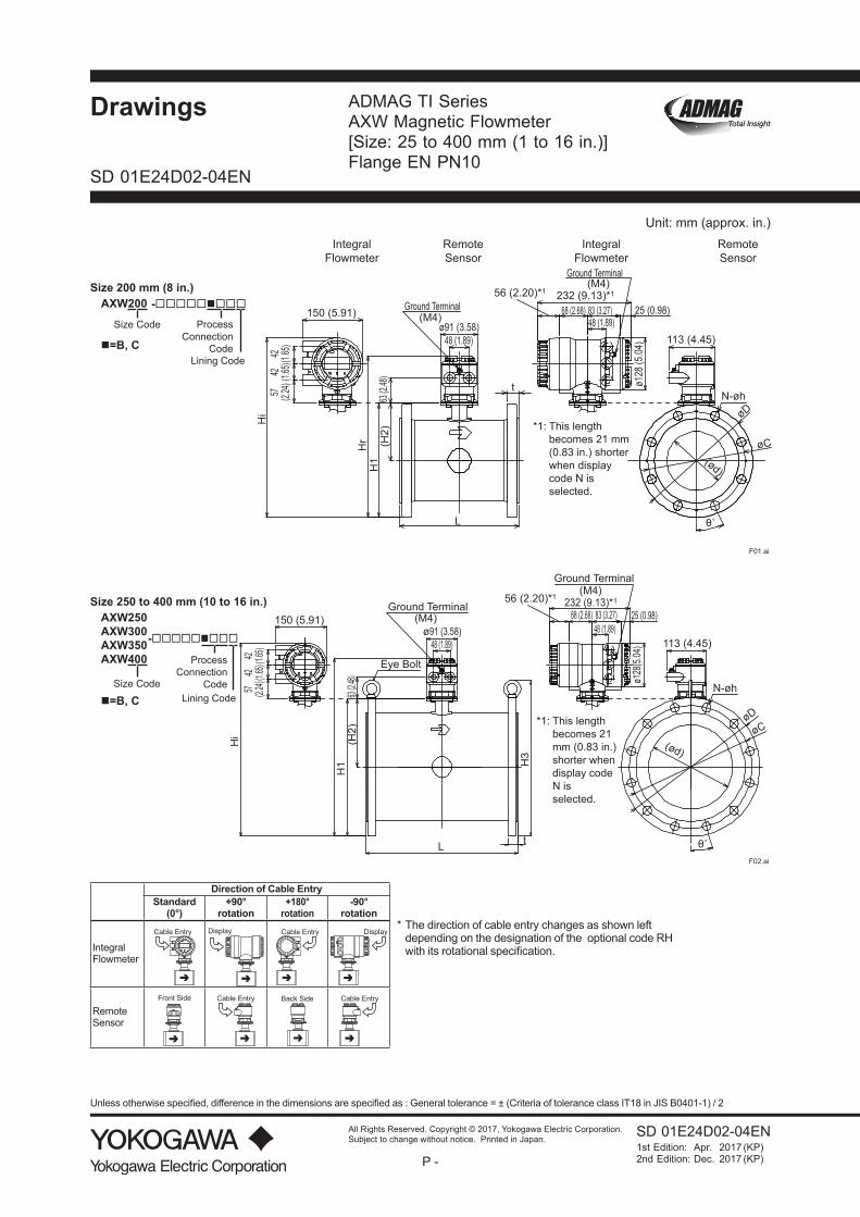
Unit: mm (approx. in.)
Model
Process Connection Code BE1CE1
Size Code 200 200 200 250 250 250 300 300 300 350 350 350 400 400 400
Size 200 200 200 250 250 250 300 300 300 350 350 350 400 400 400(8) (8) (8) (10) (10) (10) (12) (12) (12) (14) (14) (14) (16) (16) (16)
Lining Code F U H, D F U H, D F U H, D F U H, D F U H, D
Remote Sensor
Integral Flowmeter
Lay Length (*1) (*5) L 349 349 349 448 448 448 498 498 498 548 548 548 598 598 598 (13.72) (13.72) (13.72) (17.62) (17.62) (17.62) (19.59) (19.59) (19.59) (21.56) (21.56) (21.56) (23.52) (23.52) (23.52)
Flange Outer Diameter øD 340 340 340 395 395 395 445 445 445 505 505 505 565 565 565 (13.39) (13.39) (13.39) (15.55) (15.55) (15.55) (17.52) (17.52) (17.52) (19.88) (19.88) (19.88) (22.24) (22.24) (22.24)
Flange Thickness (incl. lining flare) t 28.0 28.0 28.0 31.0 31.0 31.0 30.0 30.0 30.0 30.5 30.5 30.5 30.5 30.5 30.5
(1.10) (1.10) (1.10) (1.22) (1.22) (1.22) (1.18) (1.18) (1.18) (1.20) (1.20) (1.20) (1.20) (1.20) (1.20)
Lining Inner Diameter ød 200 194 198 248 242 247 300 292 299 330 323 330 381 373 381 (7.89) (7.63) (7.81) (9.78) (9.53) (9.74) (11.79) (11.48) (11.75) (12.97) (12.70) (12.97) (14.98) (14.67) (14.98)
Bolt Circle Diameter øC 295 295 295 350 350 350 400 400 400 460 460 460 515 515 515
(11.61) (11.61) (11.61) (13.78) (13.78) (13.78) (15.75) (15.75) (15.75) (18.11) (18.11) (18.11) (20.28) (20.28) (20.28)Bolt Hole Interval θ° 22.5 22.5 22.5 15 15 15 15 15 15 11.25 11.25 11.25 11.25 11.25 11.25
Bolt Hole Diameter øh 22 22 22 22 22 22 22 22 22 22 22 22 26 26 26(0.87) (0.87) (0.87) (0.87) (0.87) (0.87) (0.87) (0.87) (0.87) (0.87) (0.87) (0.87) (1.02) (1.02) (1.02)
Number of Bolt Holes N 8 8 8 12 12 12 12 12 12 16 16 16 16 16 16
Height H1 338 338 338 396 396 396 445 445 445 497 497 497 554 554 554 (13.29) (13.29) (13.29) (15.58) (15.58) (15.58) (17.53) (17.53) (17.53) (19.55) (19.55) (19.55) (21.82) (21.82) (21.82)
Height H2 168 168 168 198 198 198 223 223 223 244 244 244 272 272 272 (6.60) (6.60) (6.60) (7.81) (7.81) (7.81) (8.77) (8.77) (8.77) (9.61) (9.61) (9.61) (10.70) (10.70) (10.70)
Height H3 - - - 446 446 446 496 496 496 565 565 565 625 625 625 (17.56) (17.56) (17.56) (19.53) (19.53) (19.53) (22.24) (22.24) (22.24) (24.61) (24.61) (24.61)
Remote Sensor
Maximum Height Hr 455 455 455 513 513 513 563 563 563 614 614 614 672 672 672
(17.91) (17.91) (17.91) (20.20) (20.20) (20.20) (22.15) (22.15) (22.15) (24.17) (24.17) (24.17) (26.44) (26.44) (26.44)Approx. Weight, Unit: kg (lb) (*2)
41 40 40 65 64 64 77 76 75 97 96 94 121 120 118 (90.5) (88.3) (88.3) (143.5) (141.3) (141.3) (170.0) (167.8) (165.6) (214.1) (211.9) (207.5) (267.1) (264.9) (260.5)
Integral Flowmeter
Maximum Height Hi 500 500 500 558 558 558 607 607 607 659 659 659 716 716 716
(19.67) (19.67) (19.67) (21.96) (21.96) (21.96) (23.91) (23.91) (23.91) (25.93) (25.93) (25.93) (28.20) (28.20) (28.20)Approx. Weight,
Unit: kg (lb)43 43 43 67 67 66 79 79 78 99 98 97 123 122 120
(94.9) (94.9) (94.9) (147.9) (147.9) (145.7) (174.4) (174.4) (172.2) (218.5) (216.3) (214.1) (271.5) (269.3) (264.9)
Grounding rings thin type (GRL, GRH) (*1) (*3) - +2 +2 - +4 +4 - +4 +4 - +4 +4 - +4 +4(+0.08) (+0.08) (+0.16) (+0.16) (+0.16) (+0.16) (+0.16) (+0.16) (+0.16) (+0.16)
Grounding rings thick type (GRN, GRJ) (*1) (*4) +6 +6 +6 +6 +6 +6 +6 +6 +6 +6 +6 +6 +6 +6 +6(+0.24) (+0.24) (+0.24) (+0.24) (+0.24) (+0.24) (+0.24) (+0.24) (+0.24) (+0.24) (+0.24) (+0.24) (+0.24) (+0.24) (+0.24)
*1: Add the value above (which is the total of both ends) to the lay length “L” when selecting optional grounding rings with/without gaskets. Also, the thickness of customer supplied gaskets should be added for getting the total lay length.
*2: When submersible use or optional code DHC is selected, waterproof glands with union joints and cables are attached. When the cable length is 30-meters, add 9.5 kg (20.9 lb) to the weight in the table.
*3: These grounding rings (GRL, GRH) are not applied to lining code F nor H but for U and D.*4: When applying these grounding rings (GRN, GRJ) to lining code F or H, gaskets supplied by customer are necessary. For
the sizes in this table, recommended thickness of the gasket is 3 to 5 mm (0.12 to 0.20 in.) per one, bringing 6 to 10 mm (0.24 to 0.39 in.) per two to be additionally added for getting the total lay length.
*5: The tolerance of the lay length “L” is as follows.• Size 25 to 200 mm (1 to 8 in.): 0/-3 mm• Size 250 to 400 mm (10 to 16 in.): 0/-5 mm
All Rights Reserved. Copyright © 2017, Yokogawa Electric Corporation.
P -
3
SD 01E24D02-04EN
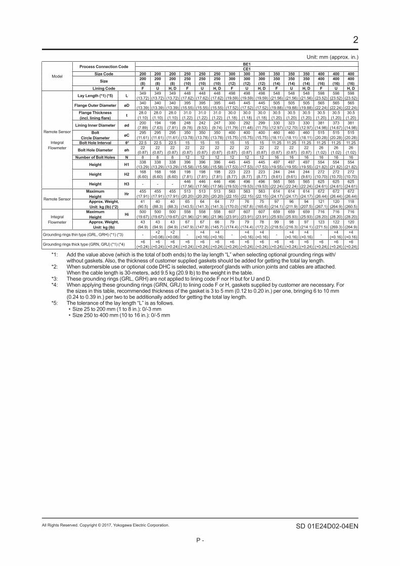
Terminal Configuration and WiringRemote Sensor:<To be wired to Remote Transmitter>
F03.ai
Flow Signal Output
Excitation Current Input
Description
Protective Grounding(Outside of the terminal box)
Terminal SymbolABC
EX1EX2
Note: When submersible use or optional code DHC is selected, waterproof glands with union joints and cables are attached.
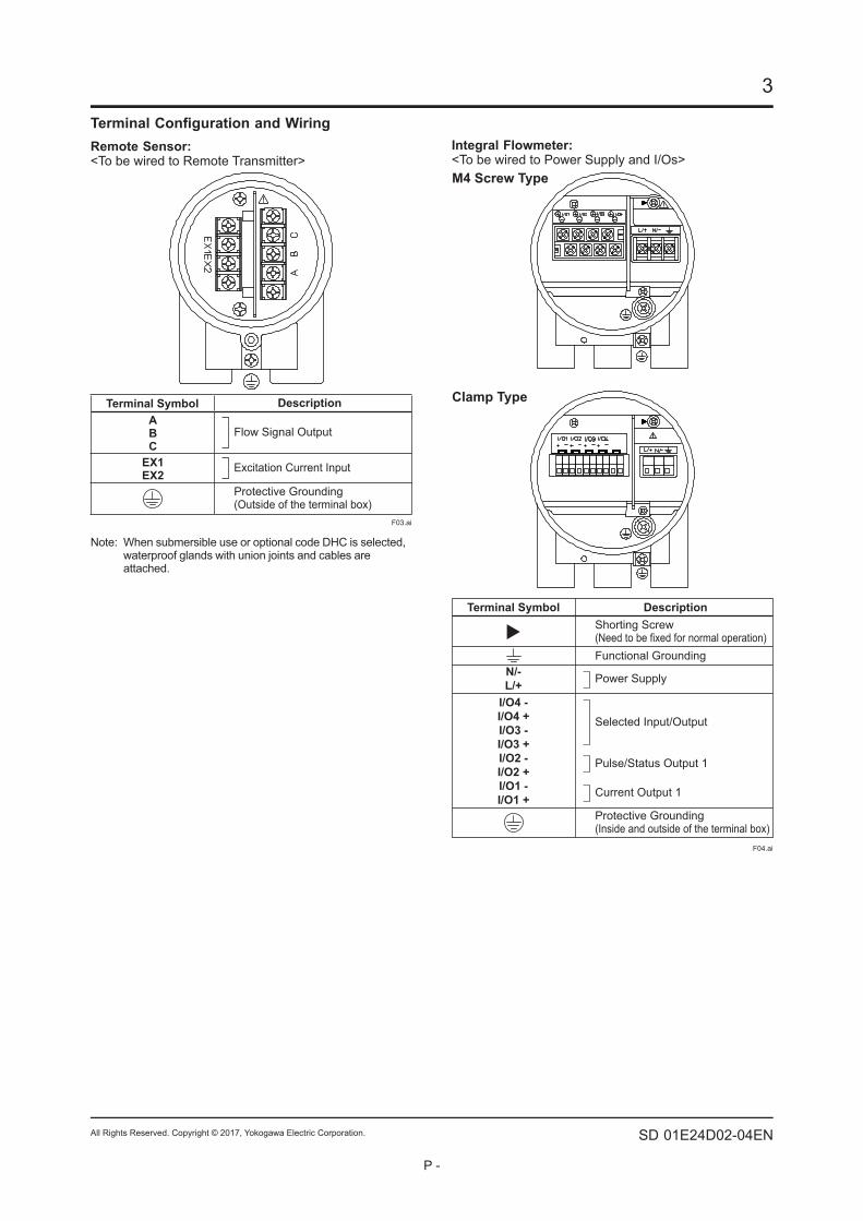
Integral Flowmeter:<To be wired to Power Supply and I/Os>
F04.ai
M4 Screw Type
Clamp Type
Terminal Symbol
N/-L/+
I/O4 -I/O4 +I/O3 -I/O3 +I/O2 -I/O2 +I/O1 -I/O1 +
Pulse/Status Output 1
Current Output 1
Selected Input/Output
Functional Grounding
Shorting Screw(Need to be fixed for normal operation)
Protective Grounding(Inside and outside of the terminal box)
Description
Power Supply
![ADMAG TI Series AXW Magnetic Flowmeter BRAIN ......ADMAG TI Series AXW MagneticFlowmeter [Size: 500 to 1800 mm (20 to 72 in.)] GeneralSpecifications GS 01E25D11-01EN AXFA11G AXF Series](https://img.pdfslide.us/doc/110x75/60c5599dd936ec767712c52e/admag-ti-series-axw-magnetic-flowmeter-brain-admag-ti-series-axw-magneticflowmeter.jpg)


![Untitled-64 [onlinepubs.trb.org] · Title: Untitled-64 Author: student Created Date: 12/1/1999 8:09:38 PM](https://img.pdfslide.us/doc/110x75/5fb6859b7c18774830208429/untitled-64-title-untitled-64-author-student-created-date-1211999-80938.jpg)


![ADMAG TI Series AXW Magnetic Flowmeter [Size: 500 to 1000 ... · ADMAG TI Series AXW Magnetic Flowmeter [Size: 500 to 1000 mm (20 to 40 in.)] Flange AS2129 Table D (Process Connection](https://img.pdfslide.us/doc/110x75/5e6c0992cc456c1983410176/admag-ti-series-axw-magnetic-flowmeter-size-500-to-1000-admag-ti-series-axw.jpg)


![ADMAG TI Series AXW Magnetic Flowmeter [Size: 500 to 1000 … · 2020-04-11 · Title: ADMAG TI Series AXW Magnetic Flowmeter [Size: 500 to 1000 mm (20 to 40 in.)] Flange ASME (Process](https://img.pdfslide.us/doc/110x75/5ecc0b8726fdee54ff16455d/admag-ti-series-axw-magnetic-flowmeter-size-500-to-1000-2020-04-11-title-admag.jpg)