Embed Size (px)
Citation preview
Strojarstvo 51 (4) 385-390 (2009) Z. BABIĆ et. al., Adjustment of Rotating Seat Pedestal... 385Adjustment of Rotating Seat Pedestal... 385 385
CODEN STJSAO ISSN 0562-1887 ZX470/1398 UDK 004.92:004.42:645.41
Professional paperThe initial design of a rotating seat pedestal contains sheet metal parts and features. The design of sheet metal parts with sheet metal features usually requires adjustment for manufacturing. In this paper we present adjustment of the rotating seat pedestal model performed in a bachelor thesis. The pedestal adjustment is carried out according to the basic manufacturing demands. During the adjustment of the model we faced some restrictions of the software used for the sheet metal modelling regarding the manufacturing demands and we presented them in this paper.
Prilagođavanje okretnog postolja sjedala za proizvodnju
Strukovni članakIzvorni dizajn okretnog postolja sjedala sadrži limene dijelove i njihove značajke. Dizajn limenih dijelova s limenim značajkama uobičajeno zahtijeva prilagođavanje za proizvodnju. U ovom radu predstavljamo prilagođavanje modela okretnog postolja sjedala izvršenog u diplomskom radu. Prilagođavanje postolja je izvedeno prema osnovnim proizvodnim zahtjevima. Prilikom prilagođavanja modela naišli smo na ograničenja softvera korištenog za dizajn limenih modela s obzirom na proizvodne zahtjeve i predstavili ih u radu.
Zdenko BABIĆ, Milan KLJAJIN andTomislav GALETA
Strojarski fakultet u Slavonskom Brodu Sveučilišta J. J. Strossmayera u Osijeku (Mechanical Engineering Faculty, University J. J. Strosmayer in Osijek), Trg Ivane Brlić-Mažuranić 2, HR-35000 Slavonski Brod, Republic of Croatia
KeywordsComputer-aided design (CAD) Sheet-metal modelling
Ključne riječiDizajn limenih modela Računalom podržan dizajn
Received (primljeno): 2006-06-25 Accepted (prihvaćeno): 2009-06-20
Adjustment of Rotating Seat Pedestal for Manufacturing
1. Introduction
The main objectives of the bachelor thesis presented in this paper were: to prepare a parametric model of a seat pedestal within CAD/CAM system and to adjust the model according to manufacturing demands. The rotating seat pedestal model was originally designed by Sportscraft Fahrzeugtechnik Ltd. for Mario-Laser Ltd. The engineers from Mario-Laser set a task for the bachelor candidate to prepare 3D parametric and feature based computer model for manufacturing based on the available technical documentation provided by Sportscraft [1]. The computer model will be used in Mario-Laser for preparation of tools and to manufacture the pedestal prototype. The rotating seat pedestal has to be built in such a way that it can resist high stress in case of a car crash, and that fact has to be considered during the design and manufacturing of the
pedestal prototype. The pedestal prototype will be tested in Sportscraft Fahrzeugtechnik Ltd.
Since the pedestal parts contain many sheet metal features, the candidate Zdenko Babić had to review available CAD software and select one that has the appropriate sheet metal module but also to select one that is acceptable for the client. During his research he received help and advice from his mentor, full professor Milan Kljajin and from senior assistant Tomislav Galeta, both from Mechanical Engineering Faculty in Slavonski Brod, Croatia.
After choosing CATIA for the design of the pedestal assembly, we found that designing sheet metal models in CATIA may require some additional software as described later in this paper. That fact and the probability that work done in the thesis is potentially interesting for a wide audience motivated us to publish it in this paper.
386 Z. BABIĆ et. al., Adjustment of Rotating Seat Pedestal... Strojarstvo 51 (4) 385-390 (2009)
2. Sheet metal modelling concept
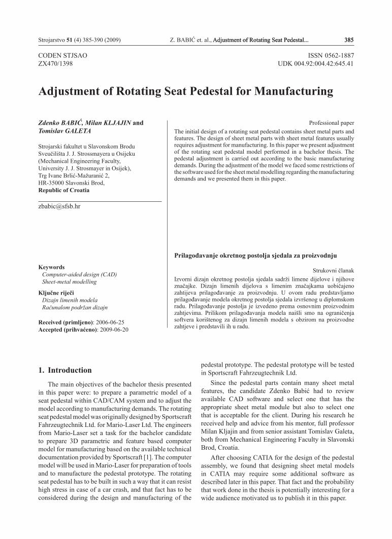
Sheet metal models are 3D computer models which have sheet plates as the base material and they are modelled in CAD systems. CAD systems for parametric designing of sheet metal models provide a flat pattern feature used for starting sheet plate calculation. The flat pattern feature is important in the manufacturing process since it provides correct cutting dimensions from the base sheet. Apart from the mentioned features, CAD system also provides the usual 3D modelling features and external variables connection possibility, which makes it easy and efficient for a quick re-design.
Figure 1 shows models of rotating seat pedestal that contains sheet metal features.
Figure 1. Sheet metal modelsSlika 1. Limeni modeli
2.1. CAD systems in design of sheet metal models
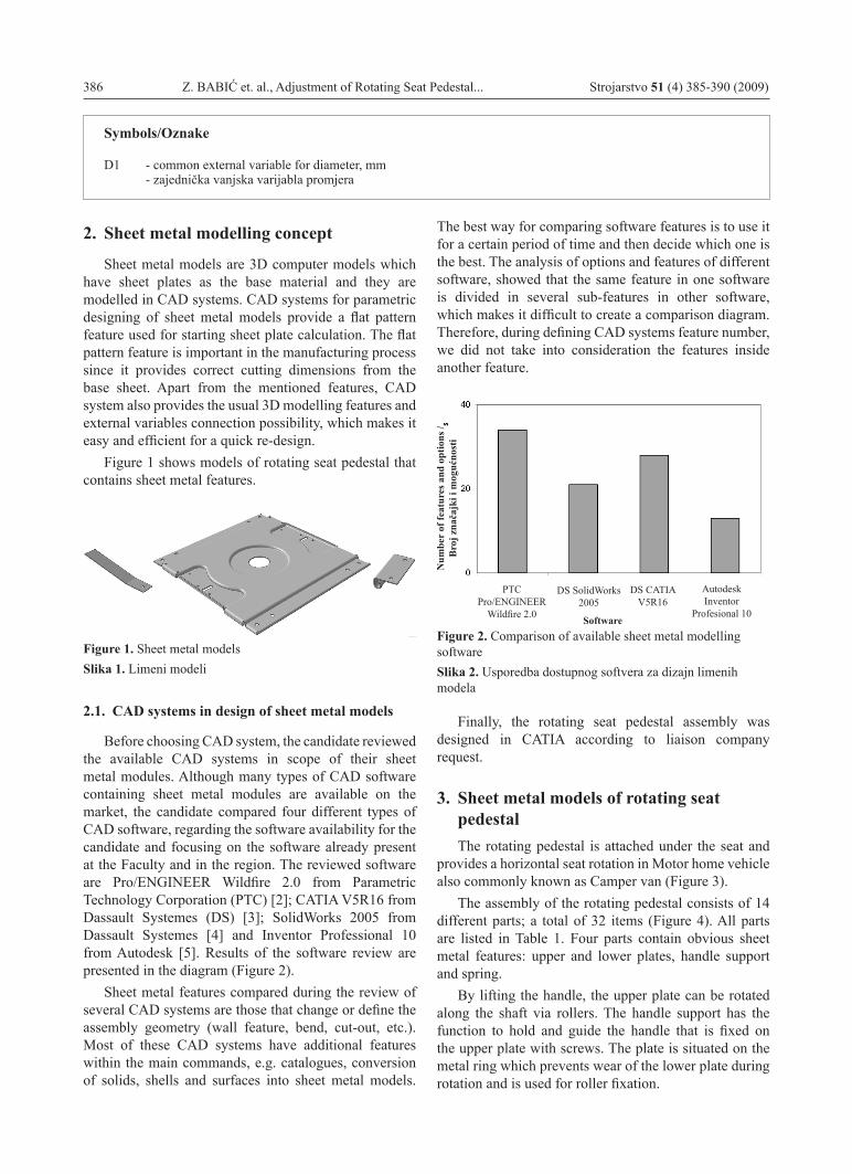
Before choosing CAD system, the candidate reviewed the available CAD systems in scope of their sheet metal modules. Although many types of CAD software containing sheet metal modules are available on the market, the candidate compared four different types of CAD software, regarding the software availability for the candidate and focusing on the software already present at the Faculty and in the region. The reviewed software are Pro/ENGINEER Wildfire 2.0 from Parametric Technology Corporation (PTC) [2]; CATIA V5R16 from Dassault Systemes (DS) [3]; SolidWorks 2005 from Dassault Systemes [4] and Inventor Professional 10 from Autodesk [5]. Results of the software review are presented in the diagram (Figure 2).
Sheet metal features compared during the review of several CAD systems are those that change or define the assembly geometry (wall feature, bend, cut-out, etc.). Most of these CAD systems have additional features within the main commands, e.g. catalogues, conversion of solids, shells and surfaces into sheet metal models.
The best way for comparing software features is to use it for a certain period of time and then decide which one is the best. The analysis of options and features of different software, showed that the same feature in one software is divided in several sub-features in other software, which makes it difficult to create a comparison diagram. Therefore, during defining CAD systems feature number, we did not take into consideration the features inside another feature.
Figure 2. Comparison of available sheet metal modelling softwareSlika 2. Usporedba dostupnog softvera za dizajn limenih modela
Finally, the rotating seat pedestal assembly was designed in CATIA according to liaison company request.
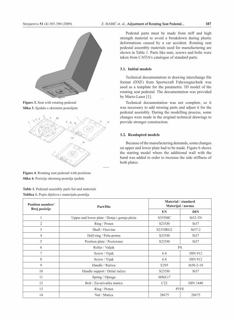
3. Sheet metal models of rotating seat pedestalThe rotating pedestal is attached under the seat and
provides a horizontal seat rotation in Motor home vehicle also commonly known as Camper van (Figure 3).
The assembly of the rotating pedestal consists of 14 different parts; a total of 32 items (Figure 4). All parts are listed in Table 1. Four parts contain obvious sheet metal features: upper and lower plates, handle support and spring.
By lifting the handle, the upper plate can be rotated along the shaft via rollers. The handle support has the function to hold and guide the handle that is fixed on the upper plate with screws. The plate is situated on the metal ring which prevents wear of the lower plate during rotation and is used for roller fixation.
Num
ber
of fe
atur
es a
nd o
ptio
ns /
Bro
j zna
čajk
i i m
oguć
nost
i
PTCPro/ENGINEER
Wildfire 2.0
DS SolidWorks2005
DS CATIAV5R16
AutodeskInventor
Profesional 10Software
Symbols/Oznake
D1 - common external variable for diameter, mm - zajednička vanjska varijabla promjera
Strojarstvo 51 (4) 385-390 (2009) Z. BABIĆ et. al., Adjustment of Rotating Seat Pedestal... 387Adjustment of Rotating Seat Pedestal... 387 387
Figure 3. Seat with rotating pedestalSlika 3. Sjedalo s okretnim postoljem
Figure 4. Rotating seat pedestal with positionsSlika 4. Pozicije okretnog postolja sjedala
Table 1. Pedestal assembly parts list and materialsTablica 1. Popis dijelova i materijala postolja
Position number/ Broj pozicije Part/Dio
Material / standardMaterijal / norma
EN DIN1 Upper and lower plate / Donja i gornja ploča S355MC St52-3N2 Ring / Prsten S235J0 St373 Shaft / Osovina S235JRG2 St37-24 Half-ring / Polu-prsten S235J0 St375 Position plate / Pozicioner S235J0 St376 Roller / Valjak PA7 Screw / Vijak 6.8 DIN 9128 Screw / Vijak 6.8 DIN 9129 Handle / Ručica E295 St50-2-1010 Handle support / Držač ručice S235J0 St3711 Spring / Opruga 60SiCr712 Bolt / Zavarivačka matica C22 DIN 144013 Ring / Prsten PTFE14 Nut / Matica 28675 28675
Pedestal parts must be made from stiff and high strength material to avoid a breakdown during plastic deformations caused by a car accident. Rotating seat pedestal assembly materials used for manufacturing are shown in Table 1. Parts like nuts, screws and bolts were taken from CATIA’s catalogue of standard parts.
3.1. Initial models
Technical documentation in drawing interchange file format (DXF) from Sportscraft Fahrzeugtechnik was used as a template for the parametric 3D model of the rotating seat pedestal. The documentation was provided by Mario-Laser [1].
Technical documentation was not complete, so it was necessary to add missing parts and adjust it for the pedestal assembly. During the modelling process, some changes were made in the original technical drawings to provide stronger construction.
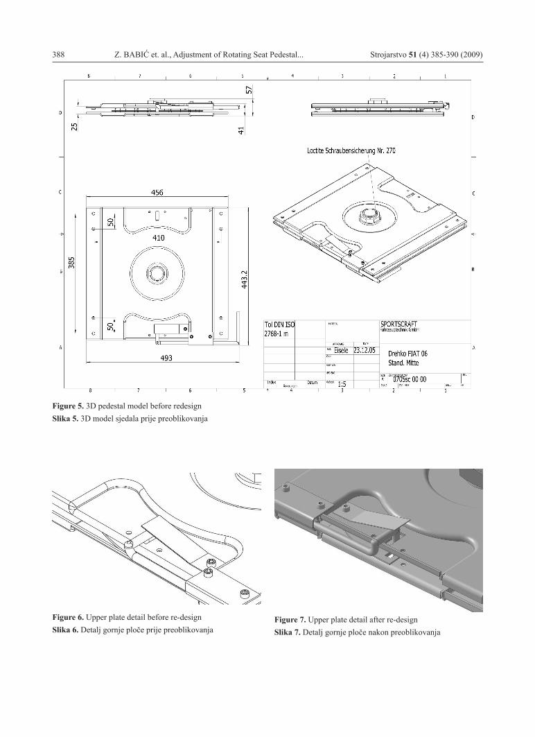
3.2. Readapted models
Because of the manufacturing demands, some changes on upper and lower plate had to be made. Figure 6 shows the starting model where the additional wall with the band was added in order to increase the side stiffness of both plates.
388 Z. BABIĆ et. al., Adjustment of Rotating Seat Pedestal... Strojarstvo 51 (4) 385-390 (2009)
Figure 5. 3D pedestal model before redesignSlika 5. 3D model sjedala prije preoblikovanja
Figure 6. Upper plate detail before re-designSlika 6. Detalj gornje ploče prije preoblikovanja
Figure 7. Upper plate detail after re-designSlika 7. Detalj gornje ploče nakon preoblikovanja

Strojarstvo 51 (4) 385-390 (2009) Z. BABIĆ et. al., Adjustment of Rotating Seat Pedestal... 389Adjustment of Rotating Seat Pedestal... 389 389
Added side walls are planned to be welded with adjacent walls to increase the side stiffness of both plates even more (Figure 7).
Relations of Rotating Seat PedestalBringing assembly and part models into parametric
relations could speed up and simplify the future assembly and model change. For these reasons, all parts of the rotating seat pedestal were set in relations. Two kinds of relations were applied during modelling of rotating seat pedestal: part parameters were connected with external variables, while parts were assembled via geometric constraints.
Static and dynamic connections are two kinds of external variables connections. If the changes made inside external variables are not propagated automatically in 3D model, then it is a static connection, and therefore it is necessary to add external variables manually. On the other hand, dynamical connected value inside 3D model automatically changes the affected features.
External variables connection with the active 3D model was made by using the design tables. Beside the dynamic connection, design tables enable quick creation of multiple variants of a model.
Table 2. Parts and features ratio of external variable D1Tablica 2. Odnosi dijelova i značajki vanjske varijable D1
Name/Naziv
Part & Position No./Dio i broj pozicije
FeatureZnačajka
MeasureIzmjera
D1
Shaft 3 / Osovina 3 Extrusion / Ekstruzija External diameter / Vanjski promjer
Nut 14 / Matica 14 Thread / Navoj Internal diameter / Unutarnji promjer
Polymer ring 13 / Polimerni prsten 13 Hole / Provrt Internal diameter / Unutarnji promjer
Position plate 5 / Pozicioner 5 Cut-out / Prosijecanje Internal diameter / Unutarnji promjer
For example, internal nut diameter, external shaft diameter, internal ring diameter and cut-out diameter in position plate have the same measures that are connected via external variable D1. After changing the external variable D1, all features that are influenced by the variable D1 are automatically changed. Figure 8 shows parts brought in relations by using the common external variable D1.
After applying geometrical constraints, all parts were set up in the correct position in the assembly model of the rotating pedestal model (Figure 9).
Figure 8. Parts related by external variable D1Slika 8. Dijelovi povezani vanjskom varijablom D1
Figure 9. Rotating pedestal modelSlika 9. Model okretnog postolja

390 Z. BABIĆ et. al., Adjustment of Rotating Seat Pedestal... Strojarstvo 51 (4) 385-390 (2009)
4. Discussion
During the process of modelling, our candidate faced some limitations of CATIA, which made it difficult to adjust the model completely to initially preferred shape. In obtaining the flat pattern from the sheet metal model which is important in manufacturing of sheet metal part, CATIA calculates only with bend features. If the model contains stamp features like those in the upper or lower plates, CATIA’s algorithm does not include them in calculation for the flat pattern and it gives the inaccurate results of flat pattern dimensions. Therefore, additional software must be used to get the accurate results, like AutoForm which uses Finite Element Method (FEM) in calculation of the flat pattern.
Work on the thesis was the result of cooperation with a manufacturing company which provided many opportunities for the candidate, the professors at the Faculty and the engineers from Mario-Laser. The candidate gained experience and valuable reference by working for a well-known manufacturing company on the concrete task in the area of sheet metal modelling. After graduation, it actually helped the candidate to get a job in that area.
The professors utilized work on the thesis to establish and attune communication protocols with manufacturing companies and with future BSc candidates. Due to the fact that electronic mail was not appropriate for exchange of numerous and large documents, all documents were shared in the digital format through document management system. Three different document management systems were tested in the beginning. After testing, we chose Linux based DocMGR as document management system [6].
Acknowledgment
Authors wish to thank BSc Goran Ilija Grgić from Mario-Laser Ltd. who provided technical documentation and valuable suggestions during the work on the thesis and during the writing of this paper and to Professor Željka Rosandić for proof-reading the manuscript.
REFERENCES
[1] Technical Documentations of Rotating Seat Pedestal, Sportscraft Fahrzeugtechnik Ltd. and Mario-Laser Ltd. Slavonski Brod, 2006.
[2] Pro/ENGINEER Wildfire 2.0 Documentation, Parametric Technology Corporation, 2004.
[3] CATIA Version 5 Release 14 Documentation, Dassault Systemes, 2005.
[4] SolidWorks 2005 Documentation, SolidWorks Corporation, 2005.
[5] Autodesk Inventor Professional 10 Help, Autodesk, Inc. 2005.
[6] DocMGR Document Management System Documentation, http://www.docmgr.org, 19. 04. 2007.