Embed Size (px)
Citation preview
Adjustable Speed Hydro Generation
J.R. Wilhelmi, J.J. Fraile Ardanuy, J.J. Fraile Mora and L. Íñigo
Departamento de Ingeniería Civil: Hidráulica y Energética E.T.S. Ingenieros de Caminos, Canales y Puertos.
Universidad Politécnica de Madrid. Prof. Aranguren s/n. Ciudad Universitaria. 28040 Madrid.
Phone: +34 91 3366714, Fax: +34 91 3366764, e-mail : [email protected]
Abstract. The potential advantages of variable speed hydroelectric generation are discussed in this paper. Some general aspects concerning the efficiency gains in turbines and the improvements in plants operation are analysed. The main results of measurements done on a test loop with an axial-flow turbine are reported. Also is described the control scheme implemented, which is based on artificial neural nets (ANN). The conclusions encourage the realisation of more detailed studies, especially for low head plants, in order to confirm the practical interest of this technology. Key words Variable Head Hydro Plants, Operation limits of Hydro Turbines, Variable-speed generation, Regenerative Frequency Converters, Artificial Neural Networks.
1. Introduction In hydroelectric power plants the speed of the generating unit must remain constant in order to keep the synchronism with the grid. Even in the smallest hydro plants with asynchronous generator the situation is basically the same, because the deviation of the generating unit from synchronism is very small. Usually, hydroturbines are optimised for an operating point defined by speed, head and discharge. At fixed-speed operation only limited deviations of head and discharge are allowed. In variable-speed turbines the allowable range of variation of the hydraulic magnitudes would be enlarged, giving rise to significant advantages in the plant operation. In [1] improvements in environmental, energy and hydraulic conditions are reported. Variable-speed technologies are presently well introduced in wind generation [2], where appreciable advantages have been found. In general a static frequency converter is needed and is worth to mention the recent advances in Power Electronics that enhance the performance of these devices. Of course the power converters increase the cost of the generating facility, but the improvements in operation that may result, and the potential net benefits that can be
obtained make this option reasonably attractive. The aim of this paper is to discuss the possible advantages of using these techniques in hydro generation, considering the main aspects related with the turbine, generator, control system and operational conditions.
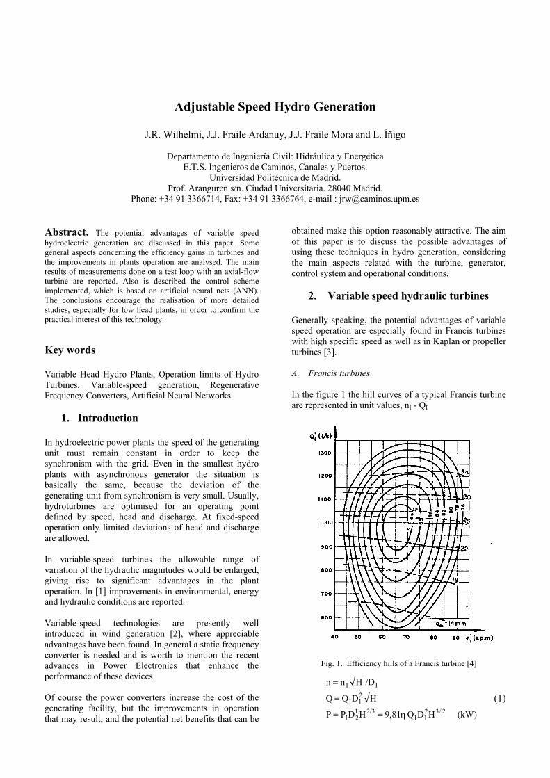
2. Variable speed hydraulic turbines Generally speaking, the potential advantages of variable speed operation are especially found in Francis turbines with high specific speed as well as in Kaplan or propeller turbines [3]. A. Francis turbines In the figure 1 the hill curves of a typical Francis turbine are represented in unit values, nI - QI
Fig. 1. Efficiency hills of a Francis turbine [4]
(kW) HDQ 9,81HDPP
HDQQ
/DHnn
2/321I
2/312I
21I
II
η==
=
=
(1)
From the figure is clear that the efficiency drops appreciably if nI deviates from the optimal values. In a constant speed turbine this occurs when the net head, H, changes. But if it were possible to modify the speed, n, the changes in the unit speed, nI , could be reduced or even suppressed, maintaining the high values of efficiency. Moreover, the speed adjustment would avoid other problems which arise when the head deviations are excessive, namely: draft tube pressure oscillations and cavitations [1],[4],[5]. In a similar way at rated head and part load a substantial increase in the efficiency may be gained by adjusting the speed to its optimum value. In this situation, if the head were reduced draft tube oscillations or shaft torque fluctuations may occur. The possibility of varying the speed avoids these inconvenients, what means a reduction in the minimum discharge. B. Propeller and Kaplan turbines The double regulation of a Kaplan turbine allows to maintain high values of efficiency in a broad range of values of head and discharge. A propeller turbine has fixed blades, its cost being appreciably lower than that of a Kaplan turbine [1]. However the efficiency drops dramatically for load values out of a narrow range in the neighbourhood of rated power. As before, variable-speed operation of a propeller turbine improves substantially its performance, although keeping it below that of a Kaplan one. Moreover, in some power plant configurations it would be possible to operate without wicket gates, with the regulation provided by the speed. Then the variable-speed propeller turbine may be a good alternative to a Kaplan turbine, because of its greater simplicity and robustness, while still maintaining good performance. The counterpart comes from the extra equipment needed for variable-speed operation on a fixed-frequency grid.
3. Variable-speed generation
In medium or large size power plants a synchronous generator is generally used. Then it is possible the connection of the plant to the grid trough a HVDC link. This solution is very attractive in remote sites when the energy has to be transmitted across long distances. With this scheme the unit speed may be varied within a ± 25% with respect to its rated value [1]. If the distances are shorter and AC transmission is used, a similar scheme may still be applied by connecting the plant through a DC link back-to-back to the grid; this configuration may also be found in wind generators [2]. In small hydro plants induction generators are frequently used, especially for the smaller units. Since this kind of machine requires a source of reactive power, the scheme described above may not be directly applied for variable-speed operation. However in a wounded rotor induction machine this is made possible by supplying variable frequency currents to the rotor winding through a
frequency converter. This is the so-called doubly fed induction generator that is extensively used in wind generators. The converter size corresponds to the slip power, which represents a fraction of the machine rated power. As an example of this scheme may be mentioned the Compuerto hydro plant, where the rotor of the 10 MW generator is fed by a thyristor cycloconverter [5]. The recent advances in power electronics allow the application of selfconmutated elements such as IGBT’s, increasing the control capabilities of the converter. Double-sided inverters may work as regenerative converters [6], making it possible to raise or lower the speed. Additionally the power factor at the grid side may be adjusted. This configuration is presently used in some wind generators. Induction generators with short-circuited rotor, such as squirrel cage ones, are cheaper and more robust, but the rotor currents can not be controlled as above. However in the smaller units the stator could be connected to the fixed-frequency grid through a regenerative converter, allowing the variable-speed operation. Of course in these cases the converter must be sized for the total generator power. This option will be examined in the following paragraphs.
4. Experimental work
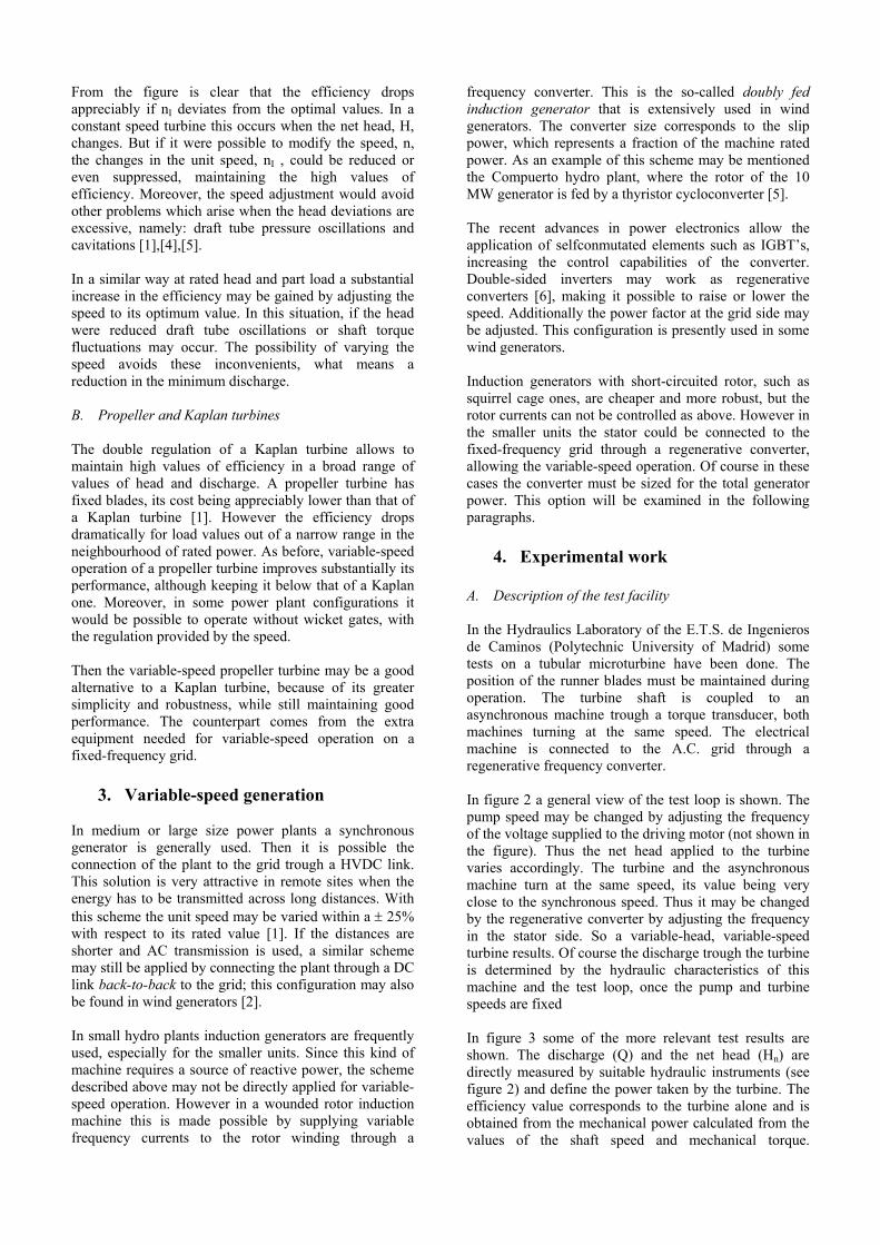
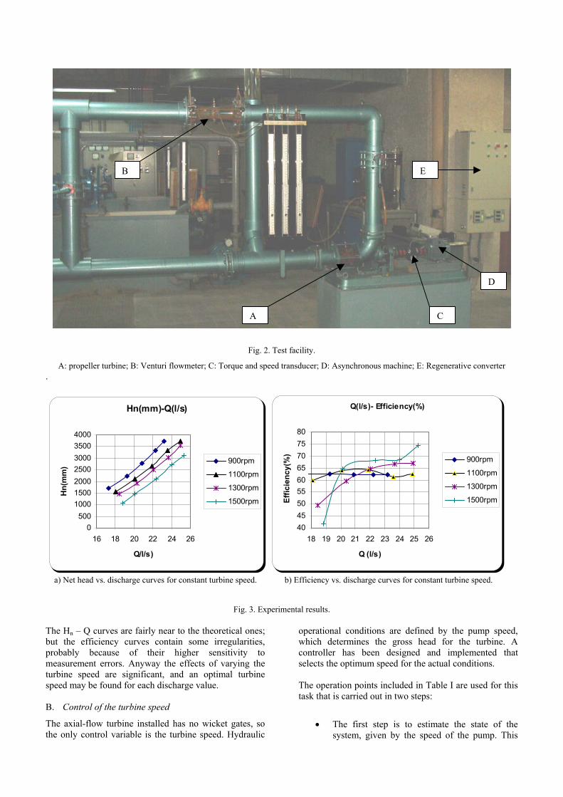
A. Description of the test facility In the Hydraulics Laboratory of the E.T.S. de Ingenieros de Caminos (Polytechnic University of Madrid) some tests on a tubular microturbine have been done. The position of the runner blades must be maintained during operation. The turbine shaft is coupled to an asynchronous machine trough a torque transducer, both machines turning at the same speed. The electrical machine is connected to the A.C. grid through a regenerative frequency converter. In figure 2 a general view of the test loop is shown. The pump speed may be changed by adjusting the frequency of the voltage supplied to the driving motor (not shown in the figure). Thus the net head applied to the turbine varies accordingly. The turbine and the asynchronous machine turn at the same speed, its value being very close to the synchronous speed. Thus it may be changed by the regenerative converter by adjusting the frequency in the stator side. So a variable-head, variable-speed turbine results. Of course the discharge trough the turbine is determined by the hydraulic characteristics of this machine and the test loop, once the pump and turbine speeds are fixed In figure 3 some of the more relevant test results are shown. The discharge (Q) and the net head (Hn) are directly measured by suitable hydraulic instruments (see figure 2) and define the power taken by the turbine. The efficiency value corresponds to the turbine alone and is obtained from the mechanical power calculated from the values of the shaft speed and mechanical torque.
A: propeller turbine; B: Venturi flowmeter; C: Torque .
Hn(mm)-Q(l/s)
0500
1000150020002500300035004000
16 18 20 22 24 26
Q/l/s)
Hn(
mm
)
900r
1100
1300
1500
a) Net head vs. discharge curves for constant turbine spe
Fig The Hn – Q curves are fairly near to the theoretical but the efficiency curves contain some irregulaprobably because of their higher sensitivitymeasurement errors. Anyway the effects of varyinturbine speed are significant, and an optimal tuspeed may be found for each discharge value. B. Control of the turbine speed
The axial-flow turbine installed has no wicket gatethe only control variable is the turbine speed. Hyd
A
B
Fig. 2. Test facility.
and speed transducer; D: Asynchronous machine;
pm
rpm
rpm
rpm
Q(l/s)- Efficiency(
404550556065707580
18 19 20 21 22 23 24 2
Q (l/s)
Effic
ienc
y(%
)
ed. b) Efficiency vs. discharge curves for
. 3. Experimental results.
ones; rities, to
g the rbine
s, so raulic
operational conditions are dewhich determines the gross controller has been designeselects the optimum speed for The operation points included task that is carried out in two s
• The first step is to
system, given by the
E
E: R
%)
5 26
const
finedhea
d athe a
in Tteps:
estim spe
C
egenerative con
900r
1100
1300
1500
ant turbine spe
by the pumd for the tund implemenctual conditio
able I are use
ate the stated of the pu
D
verter
pm
rpm
rpm
rpm
ed.
p speed, rbine. A ted that ns.
d for this
e of the mp. This
variable should be obtained from the measured values of turbine speed and generated power.
• The second step is to find the optimal turbine speed that corresponds to the actual system state. Such value determines the desired frequency in the machine side of the regenerative converter.
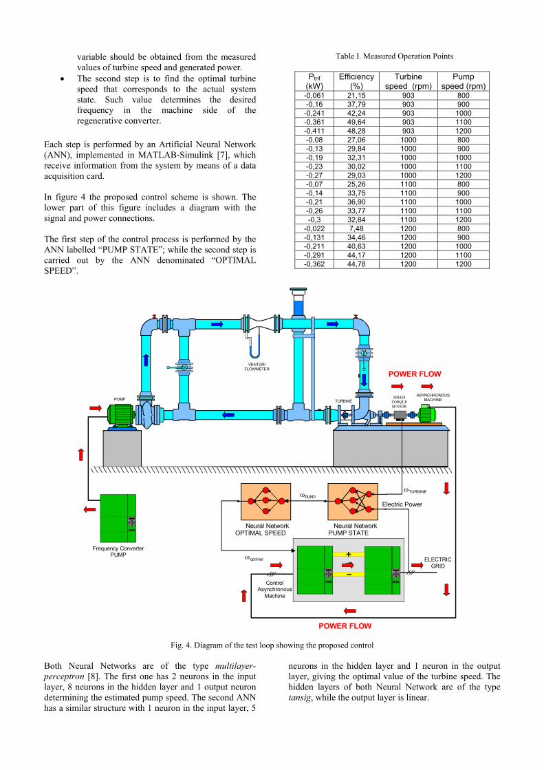
Each step is performed by an Artificial Neural Network (ANN), implemented in MATLAB-Simulink [7], which receive information from the system by means of a data acquisition card. In figure 4 the proposed control scheme is shown. The lower part of this figure includes a diagram with the signal and power connections. The first step of the control process is performed by the ANN labelled “PUMP STATE”; while the second step is carried out by the ANN denominated “OPTIMAL SPEED”.
Table I. Measured Operation Points
Ptrif (kW)
Efficiency (%)
Turbine speed (rpm)
Pump speed (rpm)
-0,061 21,15 903 800 -0,16 37,79 903 900
-0,241 42,24 903 1000 -0,361 49,64 903 1100 -0,411 48,28 903 1200 -0,08 27,06 1000 800 -0,13 29,84 1000 900 -0,19 32,31 1000 1000 -0,23 30,02 1000 1100 -0,27 29,03 1000 1200 -0,07 25,26 1100 800 -0,14 33,75 1100 900 -0,21 36,90 1100 1000 -0,26 33,77 1100 1100 -0,3 32,84 1100 1200
-0,022 7,48 1200 800 -0,131 34,46 1200 900 -0,211 40,63 1200 1000 -0,291 44,17 1200 1100 -0,362 44,78 1200 1200
Fig. 4. Diagram of the test loop showing the proposed control
Both Neural Networks are of the type multilayer- perceptron [8]. The first one has 2 neurons in the input layer, 8 neurons in the hidden layer and 1 output neuron determining the estimated pump speed. The second ANN has a similar structure with 1 neuron in the input layer, 5
neurons in the hidden layer and 1 neuron in the output layer, giving the optimal value of the turbine speed. The hidden layers of both Neural Network are of the type tansig, while the output layer is linear.
VENTURIFLOWMETER
Frequency ConverterPUMP
30
30 30
ELECTRICGRID
ωTURBINE
Electric Power
Neural NetworkPUMP STATE
ωPUMP
Neural NetworkOPTIMAL SPEED
ControlAsynchronous
Machine
ωoptimal
PUMP TURBINEASYNCHRONOUS
MACHINESPEEDTORQUESENSOR
POWER FLOW
POWER FLOW
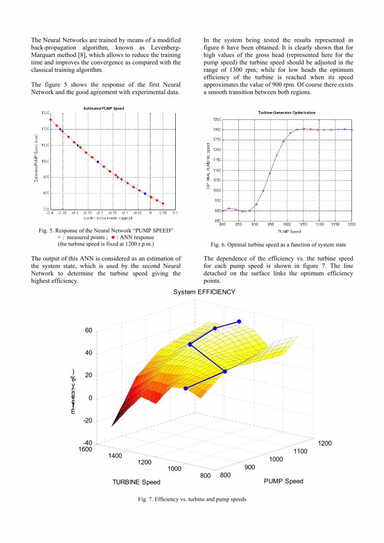
The Neural Networks are trained by means of a modified back-propagation algorithm, known as Levenberg-Marquart method [8], which allows to reduce the training time and improves the convergence as compared with the classical training algorithm. The figure 5 shows the response of the first Neural Network and the good agreement with experimental data.
Fig. 5. Response of the Neural Network “PUMP SPEED” + : measured points ; : ANN response (the turbine speed is fixed at 1200 r.p.m.)
The output of this ANN is considered as an estimation of the system state, which is used by the second Neural Network to determine the turbine speed giving the highest efficiency.
In the system being tested the results represented in figure 6 have been obtained. It is clearly shown that for high values of the gross head (represented here for the pump speed) the turbine speed should be adjusted in the range of 1300 rpm; while for low heads the optimum efficiency of the turbine is reached when its speed approximates the value of 900 rpm. Of course there exists a smooth transition between both regions.
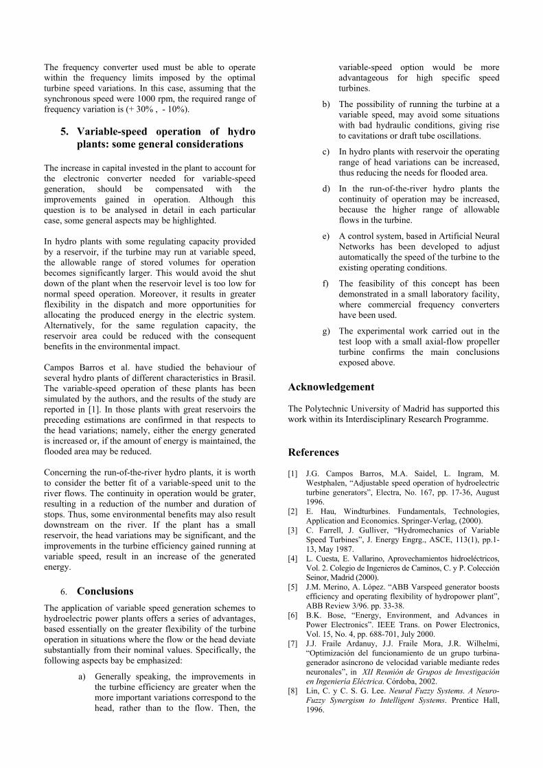
Fig. 6. Optimal turbine speed as a function of system state The dependence of the efficiency vs. the turbine speed for each pump speed is shown in figure 7. The line detached on the surface links the optimum efficiency points.
Fig. 7. Efficiency vs. turbine and pump speeds
800900
10001100
1200
8001000
12001400
1600-40
-20
0
20
40
60
PUMP Speed
System EFFICIENCY
TURBINE Speed
Efficiency (%)
The frequency converter used must be able to operate within the frequency limits imposed by the optimal turbine speed variations. In this case, assuming that the synchronous speed were 1000 rpm, the required range of frequency variation is (+ 30% , - 10%).
5. Variable-speed operation of hydro plants: some general considerations
The increase in capital invested in the plant to account for the electronic converter needed for variable-speed generation, should be compensated with the improvements gained in operation. Although this question is to be analysed in detail in each particular case, some general aspects may be highlighted. In hydro plants with some regulating capacity provided by a reservoir, if the turbine may run at variable speed, the allowable range of stored volumes for operation becomes significantly larger. This would avoid the shut down of the plant when the reservoir level is too low for normal speed operation. Moreover, it results in greater flexibility in the dispatch and more opportunities for allocating the produced energy in the electric system. Alternatively, for the same regulation capacity, the reservoir area could be reduced with the consequent benefits in the environmental impact. Campos Barros et al. have studied the behaviour of several hydro plants of different characteristics in Brasil. The variable-speed operation of these plants has been simulated by the authors, and the results of the study are reported in [1]. In those plants with great reservoirs the preceding estimations are confirmed in that respects to the head variations; namely, either the energy generated is increased or, if the amount of energy is maintained, the flooded area may be reduced. Concerning the run-of-the-river hydro plants, it is worth to consider the better fit of a variable-speed unit to the river flows. The continuity in operation would be grater, resulting in a reduction of the number and duration of stops. Thus, some environmental benefits may also result downstream on the river. If the plant has a small reservoir, the head variations may be significant, and the improvements in the turbine efficiency gained running at variable speed, result in an increase of the generated energy.
6. Conclusions
The application of variable speed generation schemes to hydroelectric power plants offers a series of advantages, based essentially on the greater flexibility of the turbine operation in situations where the flow or the head deviate substantially from their nominal values. Specifically, the following aspects bay be emphasized:
a) Generally speaking, the improvements in the turbine efficiency are greater when the more important variations correspond to the head, rather than to the flow. Then, the
variable-speed option would be more advantageous for high specific speed turbines.
b) The possibility of running the turbine at a variable speed, may avoid some situations with bad hydraulic conditions, giving rise to cavitations or draft tube oscillations.
c) In hydro plants with reservoir the operating range of head variations can be increased, thus reducing the needs for flooded area.
d) In the run-of-the-river hydro plants the continuity of operation may be increased, because the higher range of allowable flows in the turbine.
e) A control system, based in Artificial Neural Networks has been developed to adjust automatically the speed of the turbine to the existing operating conditions.
f) The feasibility of this concept has been demonstrated in a small laboratory facility, where commercial frequency converters have been used.
g) The experimental work carried out in the test loop with a small axial-flow propeller turbine confirms the main conclusions exposed above.
Acknowledgement The Polytechnic University of Madrid has supported this work within its Interdisciplinary Research Programme.
References [1] J.G. Campos Barros, M.A. Saidel, L. Ingram, M.
Westphalen, “Adjustable speed operation of hydroelectric turbine generators”, Electra, No. 167, pp. 17-36, August 1996.
[2] E. Hau, Windturbines. Fundamentals, Technologies, Application and Economics. Springer-Verlag, (2000).
[3] C. Farrell, J. Gulliver, “Hydromechanics of Variable Speed Turbines”, J. Energy Engrg., ASCE, 113(1), pp.1-13, May 1987.
[4] L. Cuesta, E. Vallarino, Aprovechamientos hidroeléctricos, Vol. 2. Colegio de Ingenieros de Caminos, C. y P. Colección Seinor, Madrid (2000).
[5] J.M. Merino, A. López. “ABB Varspeed generator boosts efficiency and operating flexibility of hydropower plant”, ABB Review 3/96. pp. 33-38.
[6] B.K. Bose, “Energy, Environment, and Advances in Power Electronics”. IEEE Trans. on Power Electronics, Vol. 15, No. 4, pp. 688-701, July 2000.
[7] J.J. Fraile Ardanuy, J.J. Fraile Mora, J.R. Wilhelmi, “Optimización del funcionamiento de un grupo turbina-generador asíncrono de velocidad variable mediante redes neuronales”, in XII Reunión de Grupos de Investigación en Ingeniería Eléctrica. Córdoba, 2002.
[8] Lin, C. y C. S. G. Lee. Neural Fuzzy Systems. A Neuro-Fuzzy Synergism to Intelligent Systems. Prentice Hall, 1996.