Embed Size (px)
Citation preview

Adjacent Channel Interference in 802.11a Is Harmful. Testbed validation of a simple quantification model.
Vangelis Angelakis1, Stefanos Papadakis2, Vasilios A. Siris2,3, Apostolos Traganitis2,4
1: Mobile Telecommunications Lab.
KTS-ITN, Linköping University
SE-601 74 Norrköping, Sweden.
2: Telecommunications & Networks Lab.
Institute of Computer Science, FORTH.
100 N Plastira, 71110 Heraklion, Greece.
3: Department of Informatics, Athens
University of Economics and Business
76 Patision, 10434 Athens, Greece.
4: Department of Computer Science,
University of Crete,
71409 Heraklion, Crete, Greece
ABSTRACT
Wireless LAN radio interfaces based on the IEEE 802.11a standard have lately foiund
wide-spread use in many wireless applications. A key reason for this was that though the
predecessor IEEE 802.11b/g had a poor channelization scheme, which resulted in strangling
adjacent channel interference (ACI), 802.11a was widely believed to be ACI-free due to a better
channelization combined with OFDM transmission. We show that this is not the case. ACI does
exist in 802.11a, and we can quantify it’s magnitude and predict its results. For this, we present
minor modifications of a simple model originally introduced by [3], that allow us to calculate
bounding values of the 802.11a ACI, which can be used in link budget calculations. Using a
laboratory testbed we verify the estimations of the model, performing experiments designed to
isolate the affected 802.11 mechanisms. This isolation was enabled by not using the wireless
medium, and by emulating it over cables and attenuators. Our results show clear throughput
degradation because of ACI in 802.11a, the magnitude of which depends on the interfering data
rates, packet sizes, and utilization of the medium.
I. Introduction
The IEEE 802.11a standard amendment describes an OFDM-based physical layer for
802.11 wireless stations operation in the 5GHz band. Due to the poor channelization of
802.11b/g that left only three of the available channels to be non-overlapping, the
channelization scheme of 802.11a was over-advertised to offer 19 non-overlapping
channels in the ETSI regulatory domain and 20 in the FCC domain. This implied that no

adjacent channel interference (ACI) was to be expected in 802.11a, and therefore no
performance degradation would be observed for neighboring links operating in
neighboring channels. Indeed, the 52 OFDM subcarriers defined in the 802.11a
amendment appear to lie well within the channel bandwidth of 20MHz, and each
channel's central frequency has a spacing of 20MHz from the next/previous adjacent
channel. Still, examining the transmit spectral mask 1 required for compliance in the
specification [2], we see that some transmitted power is allowed to leak not only to the
immediately adjacent channels, but also as far as 2 channels away from the communication
channel.
Meanwhile, the wireless network research community endorsed the 802.11a as the
standard of choice for multi-radio nodes and dense WLAN deployments. Two main
reasons were behind this: First the 2.4GHz band had been already overcrowded as the
802.11b/g compliant devices had been in the market long before the 802.11a ones and
second because it was widely believed that 5GHz capacity problems due to interference
would be mitigated by the “non-overlapping” channels promised by the standard and the
vendors. Unfortunately, although the power allowed to leak into the neighboring channels
is indeed quite low compared to the transmitted signal power, it is sufficient to cause ACI
effects, especially when neighboring radio interfaces use nearby channels, or when the
Signal to Interference-plus-Noise ratio observed at the receiver of node is marginally
larger than the threshold required to support a required rate.
Related Work
The authors of [6] performed experiments on a testbed with Atheros-based 802.11a
interfaces to examine the effect of potential ACI on a dual-radio multi-hop network. Their
work includes both in-lab and outdoor experiments using omni-directional antennas. The
former indicated that the Atheros AR5213A-chipset interfaces they employed were indeed
compliant with the spectral requirements of the 802.11a specification. Their testbed was
based on a single board Linux-based PC that hosted two interfaces and used the
opensource MadWifi driver. The outdoors experiments in that work were the first to
1 A transmit spectral masktransmit spectral masktransmit spectral masktransmit spectral mask is the power contained in a specified frequency bandwidth at certain offsets,
relative to the total carrier power
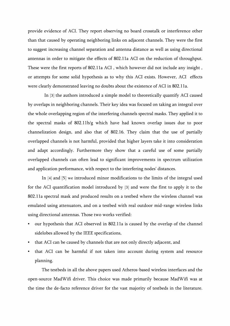
provide evidence of ACI. They report observing no board crosstalk or interference other
than that caused by operating neighboring links on adjacent channels. They were the first
to suggest increasing channel separation and antenna distance as well as using directional
antennas in order to mitigate the effects of 802.11a ACI on the reduction of throughput.
These were the first reports of 802.11a ACI , which however did not include any insight ,
or attempts for some solid hypothesis as to why this ACI exists. However, ACI effects
were clearly demonstrated leaving no doubts about the existence of ACI in 802.11a.
In [3] the authors introduced a simple model to theoretically quantify ACI caused
by overlaps in neighboring channels. Their key idea was focused on taking an integral over
the whole overlapping region of the interfering channels spectral masks. They applied it to
the spectral masks of 802.11b/g which have had known overlap issues due to poor
channelization design, and also that of 802.16. They claim that the use of partially
overlapped channels is not harmful, provided that higher layers take it into consideration
and adapt accordingly. Furthermore they show that a careful use of some partially
overlapped channels can often lead to significant improvements in spectrum utilization
and application performance, with respect to the interfering nodes' distances.
In [4] and [5] we introduced minor modifications to the limits of the integral used
for the ACI quantification model introduced by [3] and were the first to apply it to the
802.11a spectral mask and produced results on a testbed where the wireless channel was
emulated using attenuators, and on a testbed with real outdoor mid-range wireless links
using directional antennas. Those two works verified:
• our hypothesis that ACI observed in 802.11a is caused by the overlap of the channel
sidelobes allowed by the IEEE specifications,
• that ACI can be caused by channels that are not only directly adjacent, and
• that ACI can be harmful if not taken into account during system and resource
planning.
The testbeds in all the above papers used Atheros-based wireless interfaces and the
open-source MadWifi driver. This choice was made primarily because MadWifi was at
the time the de-facto reference driver for the vast majority of testbeds in the literature.

Since then the MadWifi driver has been rendered obsolete, declared legacy and is no
longer supported by the linux kernel.
In this work we provide new evidence that 802.11a ACI can be quantified and its
effects predicted. In particular, we first demonstrate the existence of 802.11a ACI on a
testbed with Atheros-based interfaces driven by the newly developed ath5k open source
driver. Second, we quantify the ACI effect in terms of goodput, completely isolating the
MAC and PHY layer mechanisms that are susceptible to its effect, using a wireless link
emulation testbed.
II. System model / ACI quantification
The Signal to Interference-plus-Noise Ratio (SINR) criterion for data reception (eq.1)
requires that the signal of interest power arriving at a receiver, over the sum of the
interference and the thermal noise powers must be above a threshold θSINR which is
defined with respect to the transmission parameters (modulation scheme) and the
quality of service requirements (data rate of transmission and reception bit error rate -
BER). In equation (1), we assume k interfering transmitters operating on the same
channel as the signal of interest transmitter, with powers Pi and Ptx respectively.
SINR
1irx)(i,irx
rx)(tx,tx θ
PathLossPN
PathLossP≥
⋅+
⋅
∑=
k
(1)
Typically, the SINR criterion is applied, as in eq. 1, in single-channel systems,
where the interfering transmissions are assumed to occupy the entire bandwidth of
the used channel and are considered as noise. In a channelization scheme where more
than one channels are used with some partial overlap on their bandwidth [3]
introduced an ACI factor Xi,rx, for each of the interferers, which can be used in the
SINR calculations. This factor depends on the spectral properties of the channels and the
transmitted signals, and the separation between the channels of an interferer i and the
receiver rx. Specifically, the affecting properties are: (i) the inter-channel spectral
distance, (ii) the channel bandwidth, (iii) the spectral mask and (iv) the receiver filter.
This factor takes values in [0, 1], with 0 indicating no overlap (i.e. complete

orthogonality), and 1 indicating that the interferer is using the same channel as the
receiver. For our work we calculate this interference factor by normalizing the spectral
mask )(fS within a frequency width w that should be at least equal to the nominal
channel width and then filter this normalized )(' fS over the frequencies that will be
within the band-bass filter of the receiver. Ideally, for the case of 802.11a, the spectral
mask should be a flat band-pass 20MHz filter, but for the sake of being more realistic we
assume that the interfaces employed use a single imperfect, wider than nominal, band-
pass filter both for transmission and reception. In the general case we could use equation
(2) to obtain the factor Xi,rx for an interferer i and a receiver rx, as a function of R '(f ), the
normalized receiver filter transfer function in [-w/2, w/2].
( ) ( )∫−
−=2
2
int, ''
w
w
irxi dfffSfRX (2)
where we have denoted by intf the frequency offset at which the interfering channel is
centered (See figure 1 ).
Finally, in a system where all radio interfaces adhere to the same protocol it is
reasonable to assume that all nodes have the same S(f ) and furthermore that this “output
filter” matches the receiver filter, and so: S(.) = R(.). Under these two assumptions, eq.(2)
becomes:
( ) ( )∫−
−=2
2
int, ''
w
wrxi dfffSfSX (3)
where we have denoted by intf the frequency offset at which the interfering channel is
centered (see figure 1 ).
S’ ( f ) S’ ( f-fint )
-w/2 0 intf w/2
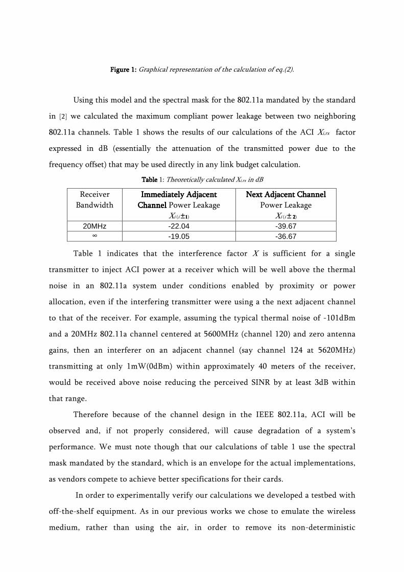
Figure 1:Figure 1:Figure 1:Figure 1: Graphical representation of the calculation of eq.(2).
Using this model and the spectral mask for the 802.11a mandated by the standard
in [2] we calculated the maximum compliant power leakage between two neighboring
802.11a channels. Table 1 shows the results of our calculations of the ACI Xi,rx factor
expressed in dB (essentially the attenuation of the transmitted power due to the
frequency offset) that may be used directly in any link budget calculation.
Table Table Table Table 1: Theoretically calculated Xi,rx in dB
Table 1 indicates that the interference factor X is sufficient for a single
transmitter to inject ACI power at a receiver which will be well above the thermal
noise in an 802.11a system under conditions enabled by proximity or power
allocation, even if the interfering transmitter were using a the next adjacent channel
to that of the receiver. For example, assuming the typical thermal noise of -101dBm
and a 20MHz 802.11a channel centered at 5600MHz (channel 120) and zero antenna
gains, then an interferer on an adjacent channel (say channel 124 at 5620MHz)
transmitting at only 1mW(0dBm) within approximately 40 meters of the receiver,
would be received above noise reducing the perceived SINR by at least 3dB within
that range.
Therefore because of the channel design in the IEEE 802.11a, ACI will be
observed and, if not properly considered, will cause degradation of a system’s
performance. We must note though that our calculations of table 1 use the spectral
mask mandated by the standard, which is an envelope for the actual implementations,
as vendors compete to achieve better specifications for their cards.
In order to experimentally verify our calculations we developed a testbed with
off-the-shelf equipment. As in our previous works we chose to emulate the wireless
medium, rather than using the air, in order to remove its non-deterministic
Receiver
Bandwidth
Immediately AdjacentImmediately AdjacentImmediately AdjacentImmediately Adjacent
ChannelChannelChannelChannel Power Leakage
Xi (i ±1111)
Next Adjacent ChannelNext Adjacent ChannelNext Adjacent ChannelNext Adjacent Channel
Power Leakage
Xi (i ± 2 2 2 2)
20MHz -22.04 -39.67 ∞ -19.05 -36.67

characteristics, avoid unknown interference, and eliminate the inherent wireless
medium uncertainty from our investigation. This led us to a laboratory testbed where
nodes’ antenna connectors were interconnected using coaxial cables, attenuators,
signal splitters and combiners. We separated the MAC & PHY mechanisms that affect
the efficiency of the protocol in the presence of ACI in order to obtain bounds for the
worse cases.
III. The Communication Mechanisms Affected by ACI in 802.11
A. Data Reception Mechanism errors
Assuming that the interference caused by 802.11a stations can be modeled as white
gaussian noise, we can determine whether the SNR requirements for the 802.11a
transmission rates, given in the specifications for 10% packet error rate, can be met under
the presence of ACI. Since each interfering node produces some ACI at the receiver
interesting interface topologies can be observed, arising by poor system design, where the
total ACI will bring the SINR at the receiver below the threshold:
i) Multi-radio nodes
In a multi-radio node, assignment of neighboring channels on interfaces that have their
antennas close together has been shown to cause reduced performance [6]. In such a
scenario the interference arriving at a receiver can be sufficiently high to be harmful due
to proximity which causes low interference path losses.
ii) Single-radio nodes
In dense topologies where channel allocation may inevitably provide nearby links of
adjacent channels, if the path losses to some receivers are high, or the number of
concurrent interfering transmissions is large then their aggregate power may be high
enough to bring the SINR below threshold.
B. Clear Channel Assessment False Negatives
The IEEE 802.11 employs a distributed coordination function (DCF) which essentially is a
CSMA/CA MAC protocol with binary exponential back-off. The DCF defines a basic access
mechanism and an optional request-to-send/clear-to-send (RTS/CTS) mechanism. Let us
consider just the basic access mechanism. In the DCF a station has to sense the channel as
clear (i.e. idle) for at least a duration of DIFS + CWmin (both defined in [1]) in order to

gain access to it. The 802.11a standard requires that a Clear Channel Assessment (CCA)
mechanism be provided by the physical layer. The CCA mechanism, that will provide this
information, is to proclaim a channel as busy when it decodes a PHY layer preamble at a
power at least equal to that of the basic rate of the 6Mbps sensitivity2, or when it detects
any signal with power 20dB above the basic transmission rate 6Mbps sensitivity.
Interference can cause the CCA to misreport in the case of nearby located
interfaces: A channel may be sensed as busy, due to high received power from a
neighboring channel that is interfering. This can occur when two nearby 802.11a
transmitters contend over different channels, such as in a poorly designed multi-radio
node. For example, in a multi-radio mesh node that has two or more interfaces using
nearby channels, with omni- or directional antennas, and with insufficient spatial
separation, or EM shielding between them.
(a) (b)
Figure Figure Figure Figure 2:2:2:2: The SINR effect on Packet Reception (a): Rx2 will not be able to correctly decode the data
transmitted by Tx2 due to high interference from nearby channel transmission of Tx1. (b)Tx2 may
report falsely the channel as busy if the Tx2�Rx2 channel is adjacent to the channel Tx1�Rx1.
IV. Experimental Verification
A. Testbed description
The testbed of our experiments consisted of four nodes interconnected using cables and
attenuators, eliminating the unpredictable wireless medium and thus fully controlling the
transmission and reception paths and losses.
Each node is an EPIA SP13000 mini-ITX motherboard with a 1.3GHz C3 CPU,
and 512MB RAM, running Gentoo Linux with the wireless testing tree kernel v.2.6.31-
2 SensitivitySensitivitySensitivitySensitivity is the minimum input power level at which decoding can be achieved at a desired BER, in a
given rate.
Rx2 Tx2 Tx1
Rx1
Channel
busy
Tx2 Tx1 Rx1
Rx2

rc8-wl. With a RouterBoard miniPCI to PCI adapter, an Atheros AR5213A chipset
miniPCI wireless interface card (CM9-GP) was used on each node, running on the ath5k
802.11a/b/g driver and hostapd v0.6.8. The ath5k driver was modified to use
independently the two antenna connectors of the wireless card, one only for transmission
and the other only for reception. This was the primary key enabler for the design of the
experiments conducted.
We also used the AirMagnet Laptop Analyzer v6.1 software to monitor the
wireless traffic and a Rohde&Schwarz FSH6 spectrum analyzer for channel power and
bandwidth verification. The interconnectivity of the nodes was routed through coaxial
cables, 4-way HyperLink Tech. splitters/combiners, Agilent's fixed attenuators (of 3, 6, 10,
20, and 50dB) and programmable attenuators by Aeroflex/Weinschel with 0 to 55.75dB
attenuation range and steps of 0.25dB. For the traffic generation and throughput
measurements we used the iperf v2.0.4 with pthreads enabled.
Before any measurement a bootstrap procedure was followed, where the wireless
interface was completely reset before applying the new settings, as a precaution catering
to the unstable nature of the ath5k driver, as our experience has shown. We generated
UDP traffic both in the interfering link and the link under test, to avoid the flow control
mechanism of TCP and thus get results for the maximum goodput at the receiver.
(a)
(b)
Figure 3Figure 3Figure 3Figure 3:::: (a)The reception mechanism testbed layout schematic representation, (b)The actual
testbed of the experiments
B. Experiments' Setup

We set up just two links to realize the scenarios of figure 2. One is the test link (figure 3a:
Link) and the second is the interference link (figure 3a: Interferer) to be tuned at a channel
neighboring the one used at the first. With these two links we were able to generate the
topologies of figure 2 and conducted two experiments. To avoid confusion, for both the
Link and the Interferer we use the term Source and Destination for the nodes that
produce and consume the iperf traffic respectively. Note that the Interferer was made
completely unaware of the Link by proper power assignment at the Link’s Sender
transmitter and the losses and isolation along the paths leading to both the receivers in
the Interferer.
Firstly we tested the ACI effect on the data reception mechanism. To do this, we
injected the traffic from the Interferer’s Sender to the receiving connector of the Link
Destination. Using the values of table 1 we calculated the transmission power required for
the interference and the attenuators values in order to bring the SINR at the receiver
below threshold.
In the second experiments set the effect of the ACI on the CCA mechanism was
examined. For this the testbed interconnection was slightly altered so that the Interferer's
Sender was coupled with the receiver of the Link's Sender. The values for the attenuators
again were calculated using table 1 and taking in mind the CCA requirements.
C. Hardware, Software and 802.11 Issues
Transmission Transmission Transmission Transmission ppppower instabilityower instabilityower instabilityower instability
A major aspect of the interference mechanism is the initial transmission power, which
together with the path losses determine the received interference power. Unfortunately
early experiments showed that the power control in the ath5k driver is not yet stable
enough; for given power settings the actual output power depended on the data rate of
the transmitted data, which appeared to be arbitrary and not due to an expected power
cutoff at higher rates. To deal with this instability, at each data rate setting we measured
the received power at some fixed point of our testbed during a calibration run, and based
on the measured value we compensated accordingly by adjusting the attenuators.

In order to verify the theoretical assumptions presented in Section 2 we coupled
the measured SINR with the achievable throughput. In each data rate the expected
throughput is relative to the SINR as for each constellation and coding rate the BER is
directly linked to the SNR [7]. With the use of the programmable attenuator we were
able to control the signal attenuation per dB and therefore we obtained measurements
that cover in detail a wide SNR space for each data rate.
Antenna Antenna Antenna Antenna isolationisolationisolationisolation instabilityinstabilityinstabilityinstability
Another major problem for designing and conducting the experiments was the separation
of transmission and reception to the two antenna connectors on the wireless card.
Unfortunately, disabling the antenna diversity option in the ath5k driver was not enough.
The result was to have some sparse transmissions from the antenna connector designated
for reception, reducing the accuracy of measurements. The problem was solved by making
the appropriate corrections in the source code for the antenna connector handling in the
ath5k driver.
Another interesting observation was that the ath5k/Atheros chipset combination
had a periodical 3 second timeout during transmission. It was easily observed as a gap in
channel utilization graph during heavy traffic generation. This behavior could be
attributed to the periodical re-calibration of the RF frontend that the wireless cards
perform. The result was the lack of interference during that period, giving a chance for
unhindered communication in the Link.
The role of The role of The role of The role of channel uchannel uchannel uchannel utilization tilization tilization tilization
One key aspect of the interference generated by 802.11 devices is that it is not constant in
time. It follows the timings of the 802.11 DCF, and can be considered as noise that is
there only during the time that the interfering transmitter is active. Therefore its effect
will depend on the utilization of the interfering link. As seen in [10] the utilization of the
wireless medium is inversely proportional to the data rate being used for a given
achievable throughput. It is a quite interesting observation that even at the maximum
achievable throughput, the utilization of the 54Mbps data rate is far lower than that of
the 6Mbps rate. Therefore one can expect that a 6 Mbps interfering sender running at
full throughput will be more harmful than a full throughput 54Mbps interferer.

With the interface connectivity explained in IV.B, we managed to produce an
802.11a jammer that does not sense the channel prior to transmitting, and therefore can
transmit as frequent as a single user DCF allows it, thus maximizing the utilization of the
medium for its respective data rate.
D. Experimental Results
Packet CapturePacket CapturePacket CapturePacket Capture
The rate in the link under investigation was always fixed, having disabled the automatic
rate selection mechanism. For each rate we increase the attenuation level at the
programmable attenuator X (see fig 3a) by one dB per measurement run. Essentially we
decrease the SINR by one dB in each step and we record the average throughput for a 3
minute measurement run period. For each data rate we have a signal strength
measurement for an attenuation value in order to have the differences in transmission
powers between them. The differences in the transmission power of each rate are used to
compensate the attenuation levels so that the results of the throughput to be directly
comparable. The results are presented in figure 4. It is obvious that the throughput curves
closely follow the expected SINR - throughput degradation, e.g. as computed in [9].
Figure 4:Figure 4:Figure 4:Figure 4: Results of the packet capture experiment.
Interferer’s rate effectInterferer’s rate effectInterferer’s rate effectInterferer’s rate effect

As we have already stated in the previous section all the experiments were conducted
with fixed rate and given utilization at the interferer. In this experiment we investigated
whether the data rate of the interferer has any impact on the interference experienced by
the receiver. In order to have comparable results for each data rate we adjust the packet
size to keep the utilization fixed. The results revealed that the data rate of the interferer
has a strong impact, with increasing intensity at higher data rates. The reasons may be the
constellation which becomes denser at higher rates and the transmission-idle time
distribution. Since the ath5k driver always keeps the basic rate at 6Mbps to verify the
above assumption we used also a Cisco 1240 AP where different basic rates (6, 12, and
24Mbps) can be defined. With the Cisco AP we saw similar behavior, but with an even
greater degradation in throughput. Although all the parameters were the same and it is
was expected that the devices should behave the same, we noticed that different devices
do have some minor differences that result in different ACI. The differences can be
attributed to protocol timing parameters as the Cisco AP consistently achieves higher
throughput than the Atheros/ath5k in an interference-free environment.
In order to further investigate the transmitting-idling time distribution theory we
used a series of packet sizes (1-1472bytes) for the throughput measurement. We took a
baseline measurement with absence of ACI and then we produced ACI keeping the same
utilization with three different data rates (6, 24,54Mbps). In 6Mbps we had a throughput
degradation of 55-58% of the baseline, in 24Mbps 63-67% and in 54Mbps about 80-91%
with the greater degradation in larger packet sizes. This result verifies that the
mechanism behind the rate effect of the ACI is the distribution of transmission and idle
times, as the long term medium utilization may be constant but the interleaved
transmitting-idle periods are denser in higher data rates.
CCACCACCACCA
In this experiment we have set channel 60 for the test Link and performed a baseline
measurement of the achieved throughput using 1000bytes UDP payload, without any
interference and for all possible data rates (Table 2 col. 1). The values of the attenuators
were properly calculated so that an interferer with output power 0dBm tuned to the
adjacent channel, would trigger false positives in the CCA mechanism of the test link

Sender. A second series (column 2) was recorded with the interferer at the same channel
as the test link where the CCA mechanism is expected to be triggered –this marks the
results of a collocated and non contending transmitter at the same channel as the Link.
Tuning the interferer at channel 56 resulted in a throughput loss ranging from 55% at
6Mbps to 85% at 54Mbps, which of course is due to the busy medium state that the
transmitter is frequently sensing. As it is obvious from Table 2 for the same transmission
power level two channels away (ch. 52) the CCA mechanism is not affected. In Table 1
we observe that the difference in power leakage between adjacent and next adjacent
channel is 18dB. With that in mind we raised the transmission power by 18dB, and
observed that the CCA mechanism was again triggered, verifying once more our model of
figure 1. The similar results of all the columns where the CCA was triggered indicate the
binary nature of the mechanism: if the received power exceeds the threshold regardless of
the channel distance the medium is sensed as busy.
TablTablTablTable 2: e 2: e 2: e 2: ACI effect on the throughput, in Mbps due to CCA
false positives
Link at channel 60 Interferer at Channel
Tx Rate (Mbps) Baseline 60 56 52 52
(+18dB)
6 4.86 2.21 2.54 4.94 2.23
9 6.92 3.03 3.10 7.91 2.32
12 8.92 3.12 2.67 9.01 2.12
18 11.81 3.15 2.71 11.72 2.29
24 14.30 3.20 2.78 14.10 2.46
36 18.11 3.40 2.81 18.21 2.65
48 21.13 3.00 2.82 21.19 2.33
54 23.11 3.26 2.95 22.10 2.71
IV. Conclusions
Despite the general belief that the 802.11a is free of ACI, due to the use of non-
overlapping channels, we have shown that the need for careful channel selection is also
present in the 5GHz band. Through the use of the emulated wireless medium we have
isolated the affected 802.11 mechanisms and quantified the throughput degradation due
to ACI. The two main mechanisms that are affected are the data reception and the clear

channel assessment. In the first case, the SNR is degraded making reception impossible,
and in the second case the transmitter stalls its data as it incorrectly senses the medium
busy. Nevertheless, the large number of channels available in 802.11a, taking into
consideration the facts identified and justified in this paper, provide the opportunity and
motivation respectively for meticulous channel selection in order to achieve high
throughput.
ACKNOWLEDGEMENTS
This work was supported by the General Secretariat for Research and Technology,
Greece, through project 05-AKMON-80 and by the European Commission in the 7th
Framework Programme through project EU-MESH (Enhanced, Ubiquitous, and
Dependable Broadband Access using MESH Networks), ICT-215320, http://www.eu-
mesh.eu.
The authors acknowledge the help of Mr. Nick Kossifidis on the testbed setup and the
modifications of the ath5k code.
REFERENCES
[1] IEEE 802.11, Wireless LAN Medium Access Control (MAC) and Physical Layer (
PHY) Specifications, Standard, IEEE, August 1999.
[2] IEEE 802.11a, Part 11: Wireless LAN, Medium Access Control (MAC) and
Physical Layer (PHY) Specifications: High-Speed Physical Layer in the 5 GHz
Band, supplement to IEEE 802.11 Standard, September 1999.
[3] A.Mishra, et.al., “Partially Overlapped Channels Not Considered Harmful”,
SIGMetrics/Performance’06, Saint Malo, France, Jun., 2006.
[4] V. Angelakis, S. Papadakis, V. Siris and A. Traganitis, “Adjacent Channel
Interference in 802.11a: Modeling and Testbed validation”, 2008 IEEE Radio and
Wireless Symposium, Orlando, FL, USA, Jan. 2008.
[5] V. Angelakis, S. Papadakis, N. Kossifidis, V. A. Siris, A. Traganitis, “The Effect of
Using Directional Antennas on Adjacent Channel Interference in 802.11a:
Modeling and Experience With an Outdoors Testbed”, WiNMee 2008, Berlin,
Germany, March 2008.

[6] C. M. Cheng, P. H. Hsiao, H. T. Kung, and D. Vlah, “Adjacent Channel
Interference in Dual-radio 802.11 Nodes and Its Impact on Multi-hop
Networking”, IEEE GLOBECOM 2006, San Francisco, CA, USA, Nov. 2006.
[7] J. Proakis, Digital Communications, 4th ed. McGraw Hill, Intl. ed., 2001.
[8] J. Robinson, K. Papagiannaki, C. Diot, X. Guo, and L. Krishnamurthy,
“Experimenting with a Multi-Radio Mesh Networking Testbed”, 1st workshop on
Wireless Network Measurements (WiNMee 2005), Italy, Apr. 2005.
[9] D.Qiao, S.Choi, and K.G. Shin, "Goodput Analysis and Link Adaptation for IEEE
802.11a Wireless LANs", IEEE Trans. On Mobile Computing, v.1, Nr.4, Oct-Dec
2002. p.p. 278-292.
[10] Jun J., Peddabachagari P., Sichitiu M. “Theoretical Maximum Throughput of IEEE
802.11 and its Applications”, IEEE NCA’03, Cambridge MA., USA, Apr. 2003.

BIOGRAPHIES
Vangelis Angelakis [StM ’05, M’09] ([email protected]) is a postdoctoral research
fellow at the Mobile Telecommunications Group of the Department of Science and
Technology in the University of Linköping, Sweden. He received the BSc, MSc, and PhD
degrees from the Department of Computer Science at the University of Crete, Greece, in
2001, 2004 and 2008 respectively. In the summer of 2005 he was a visiting researcher at
the Institute of Systems Research of the University of Maryland at College Park, USA.
Since 2004 he has been working as a research assistant and a postdoctoral research fellow
with the Telecommunications and Networks Laboratory at FORTH-ICS. His research
interests include wireless network planning and resource allocation optimization &
management.
Stefanos Papadakis [StM’07, M’10] ([email protected]) is a research & development
engineer at the Institute of Computer Science of FORTH. He received his degree in
Physics (2001) and his M.Sc. (2004) & Ph.D. (2009) degrees in Computer Science from
the University of Crete, Greece. Since 2001 he has been working as a research assistant in
the Telecommunications and Networks Laboratory at FORTH-ICS. His research interests
include position location techniques in wireless networks, radio propagation modeling
and wireless network planning.
Vasilios A. Siris [M’98] ([email protected]) is an Assistant Professor at the Department of
Informatics of the Athens University of Economics and Business, and a Research
Associate at the Institute of Computer Science of FORTH. He received the degree in
Physics (1990) from the National and Kapodistrian University of Athens, Greece, his M.S.
(1992) in Computer Science from Northeastern University, Boston, USA, and his Ph.D.
(1998) in Computer Science from the University of Crete, Greece. In Spring 2001 he was
a Visiting Researcher at the Statistical Laboratory of the University of Cambridge, and in
Summer 2001 and 2006 he was a Research Fellow at the research laboratories of British
Telecommunications (BT), UK. His research interests include resource management in
wired and wireless networks, and traffic measurement and analysis for QoS monitoring
and anomaly detection.
Apostolos Traganitis, PhD - Dr. Traganitis joined ICS, FORTH in 1988 and since then he
co-ordinated and participated in a number of EU funded projects in the Communications
and Health Care sector. He is the Head of the Telecommunications and Networks
Laboratory and a Professor in the Department of Computer Science, University of Crete,
where he also teaches and does research in the areas of Digital Communications and
Wireless Networks. Prof. Traganitis holds M.Sc. and PhD degrees from Princeton
University, USA.

Figure 1:Figure 1:Figure 1:Figure 1: Graphical representation of the calculation of eq.(2).
S’ ( f ) S’ ( f-fint )
-w/2 0 intf w/2

(a) (b)
Figure Figure Figure Figure 2:2:2:2: The SINR effect on Packet Reception (a): Rx2 will not be able to correctly decode the data
transmitted by Tx2 due to high interference from nearby channel transmission of Tx1. (b)Tx2 may
report falsely the channel as busy if the Tx2�Rx2 channel is adjacent to the channel Tx1�Rx1.
Rx2 Tx2 Tx1
Rx1
Channel
busy
Tx2 Tx1 Rx1
Rx2

(a)
(b)
Figure 3Figure 3Figure 3Figure 3:::: (a)The reception mechanism testbed layout schematic representation, (b)The actual testbed
of the experiments

Figure 4:Figure 4:Figure 4:Figure 4: Results of the packet capture experiment.