Embed Size (px)
Citation preview

Addressing and Confi guration Guide
featuring QuickPlay ProVersion 1.1
For use with CK Intelligent SeriesColor-Changing Fixtures

3Addressing and Confi guration Guide | QuickPlay Pro PUB-000224-01 R02
IntroductionWelcome to QuickPlay Pro .......................................................................................6 About QuickPlay Pro ..............................................................................................6 Key Features of QuickPlay Pro ............................................................................6 New Features QuickPlay Pro, Version 1.1 ........................................................6Understanding Addressing .........................................................................................7 Why Do You Address Lighting Systems? ...........................................................7 What is DMX512? ....................................................................................................7 Light Numbers ..........................................................................................................7 Default Light Numbers ...........................................................................................7 Fixtures Using More than Three Channels of Data .......................................7 Chromasic and Chromacore Fixtures ................................................................7Addressing Methods ....................................................................................................7 Serial Addressing ......................................................................................................7 PDS Configuration ...................................................................................................8 Ethernet Configuration ..........................................................................................8Using QuickPlay Pro ....................................................................................................8 QuickPlay Pro Interface Overview .....................................................................8 Controller Selection ................................................................................................9 Port Selection ...........................................................................................................9 Select DMX addresses for Effect .........................................................................9 More Information .....................................................................................................9 Firmware Version .....................................................................................................9 Effects ..........................................................................................................................9 Log Color ...................................................................................................................9 Tool Selection ...........................................................................................................9 Test Channels Tool ............................................................................................... 10 PDS Configuration Tool ...................................................................................... 10 Fixture Configuration Tool ................................................................................. 10 Address Fixtures Tool ..........................................................................................11 Import / Export Serial Number Tool ...............................................................12 Work Area ...............................................................................................................12 Status Log .................................................................................................................12
Options and Help ...................................................................................................12 Keyboard Shortcuts ..............................................................................................12QuickPlay Pro Addressing Procedures .................................................................13 Configuring a Chromasic Fixture on a DMX Network ..............................13 Configuring a Chromacore Fixture on a DMX Network ...........................13 Assigning a light number to a ColorReach Powercore Fixture .................14 Configuring an iColor Accent Powercore Fixture ........................................14 Renaming an Ethernet Data Enabler or Ethernet PDS ................................15QuickPlay Pro Testing Procedures ........................................................................15 Test Groups of DMX addresses ........................................................................15 Test Individual DMX addresses ..........................................................................15Using the Address Fixtures Tool ...........................................................................16Using the Import / Export Serial Number Feature ..........................................16Using the QuickPlay Pro Menus .............................................................................17Configuring Fixtures for 16-bit Resolution .........................................................17Using White Light Systems in DMX or Ethernet-based Environments ..... 18Working with RDM Fixtures ................................................................................. 18
Recommended Addressing and Configuration MethodsColorBlast® 6 with PDS-150e ................................................................................ 20ColorBlast® 12 with PDS-150e .............................................................................. 21ColorBlast® Powercore with Data Enabler DMX ............................................ 22ColorBlast® Powercore with Data Enabler Ethernet ...................................... 23ColorBlast® TR withPDS-750 TR ......................................................................... 24ColorBlaze® ............................................................................................................... 25ColorBurst® 6 with PDS-150e ............................................................................... 26ColorGraze™ Powercore with Data Enabler DMX ......................................... 27ColorGraze™ Powercore with Data Enabler Ethernet ................................... 28ColorReach™ Powercore with Data Enabler DMX ......................................... 29ColorReach™ Powercore with Data Enabler Ethernet ................................... 30C-Splash™ 2 with PDS-150e ................................................................................... 31eW® Flex SLX with PDS-60ca 24V DMX .......................................................... 32
Table of Contents

4Addressing and Confi guration Guide | QuickPlay Pro PUB-000224-01 R02
iColor® Accent Powercore with Data Enabler EO .......................................... 33iColor® Cove EC with sPDS-60ca 24V DMX / Ethernet ............................. 34iColor® Cove MX Powercore with Data Enabler DMX ................................ 35iColor® Cove MX Powercore with Data Enabler Ethernet .......................... 36iColor® Cove QLX with sPDS-60ca 24V DMX / Ethernet ........................ 37iColor® Cove QLX with PDS-60ca 24V DMX / Ethernet .......................... 38iColor® Cove QLX with sPDS-480ca 24V Ethernet .................................... 39iColor® Flex SL with PDS-60ca 7.5V DMX / Ethernet ................................... 40iColor® Flex SL with sPDS-480ca 7.5V Ethernet ..............................................41iColor® Flex SLX with sPDS-480ca 12V Ethernet ........................................... 43iColor® Module FX with PDS-60ca 7.5V DMX / Ethernet ........................... 44iColor® MR g2 with PDS-70mr 24V DMX ......................................................... 45iColor® MR g2 with PDS-70mr 24V Ethernet ................................................... 46iColor® Tile FX 2:2 with PDS-60ca 7.5V DMX / Ethernet ........................... 47iW® Blast Powercore with Data Enabler DMX ................................................ 48iW® Blast Powercore with Data Enabler Ethernet .......................................... 49iW® Blast TR with PDS-750 TR ............................................................................ 50iW® Cove Powercore with Data Enabler DMX ............................................... 52iW® Cove Powercore with Data Enabler Ethernet ......................................... 53iW® Profile g2 with PDS-150e ............................................................................... 53
Mapping Fixtures with the Address Fixtures ToolAdding Fixtures to the Fixture List ...................................................................... 55Adding Fixtures to the Map ................................................................................... 55Working with Fixtures on the Map ...................................................................... 56Sorting Fixtures ......................................................................................................... 56Program Fixtures ....................................................................................................... 56Exporting a List of Fixtures and their DMX Addresses ................................. 57
Configuring Power / Data Supplies using Onboard ControlssPDS-480ca 7.5V / 12V / 24V Ethernet ............................................................... 59sPDS-60ca 24V DMX / Ethernet ...........................................................................61
AppendicesAppendix A: DMX Tables ....................................................................................... 64Appendix B: Addressing Tools Quick Reference.............................................. 66
Appendix C: CKDMX / ESTA DMX Crossover Cable ....................................67Appendix D: 16-bit DMX address Mapping ........................................................67

5Addressing and Confi guration Guide | QuickPlay Pro PUB-000224-01 R02AddAddddresressinng ag ag ag aaandndndnd nd ConConfi gfi guratioion Gn Gn Guiduide e || Qu Q ickickkPlaPlaPlay Py y ro PUB-P 000200224-002 1 R01 R02
Introduction Addressing is the process of programming lighting fixtures with DMX addresses so that a playback controller can properly route light output data.
There are wide-ranging lighting system configurations, each with a specific combination of fixtures and Power / Data Supplies or Data Enablers. This document contains step-by-step addressing, configuration, and testing methods for a wide variety of Philips Color Kinetics lighting system configurations.
Refer to your lighting system user documentation for physical installation instructions. Installation Instructions, User Guides, Specification Sheets, and Product Guides can be found online at: www.colorkinetics.com/support

6Addressing and Confi guration Guide | QuickPlay Pro PUB-000224-01 R02
Welcome to QuickPlay Pro About QuickPlay ProWelcome to QuickPlay Pro, the multi-feature lighting system software from Philips. QuickPlay Pro allows you to configure, test, and demonstrate lighting systems via computer (PC or Mac).
InstallationQuickPlay Pro is easy to download and install. Download the installation file appropriate for your operating system from www.colorkinetics.com/support/addressing/download, then unzip the installation files.
If using Windows• ®, double-click Install QuickPlay Pro.exe to begin installation, then follow the on-screen prompts.
If using Mac OS X, drag the application from the disk image to your • Applications folder. You can then eject and delete the disk image, as desired.
Once the installation is complete, connect your computer to the lighting network:
• If working with a DMX lighting installation, use a SmartJack Pro or iPlayer® 3 to connect the computer to the lighting network.
• If working with an Ethernet lighting installation, connect your computer directly to a lighting network Ethernet switch. SmartJack Pro or iPlayer 3 is not used.
After connecting to the lighting network, addressing fixtures using QuickPlay Pro is quick and easy:
• If addressing Chromacore® fixtures in a DMX lighting network, you can enter fixture serial numbers and assign DMX addresses, or you can automatically configure fixtures by importing a spreadsheet listing each fixture’s serial number and corresponding DMX address.
• If working with Chromasic® fixtures in a DMX network, you can program a Power / Data Supply with a base light number. The base light number allows the LED nodes within each attached fixture to receive the correct light output data.
• If working with an Ethernet lighting installation, QuickPlay Pro automatically discovers all of your fixtures, Ethernet Data Enablers, and Ethernet Power / Data Supplies for quick configuration. QuickPlay Pro allows you to rename Ethernet devices and change their IP addresses.
Key Features of QuickPlay Pro
Feature Description
Serial Addressing Set DMX addresses based on fixture serial numbers.
PDS Configuration Configure a base light number on a Power / Data Supply. The base light number enables the Power / Data Supply to send correct light output data to each attached fixture.
iColor® Accent Powercore Configuration
Configure a base light number and set pixel resolution on an iColor Accent Powercore fixture. When programmed with a base light number and a pixel resolution value, each pixel within the fixture can display the correct data.
ColorReach™ Powercore Configuration
Set DMX addresses based on fixture serial numbers. Configure ColorReach Powercore fixtures for “full fixture” or “half fixture” control.
TestRapidly verify the DMX addresses you have configured. You can also test a specific DMX value on one or more channels.
Live Demonstration Select from four built-in light effects: fixed color, color wash, rainbow, and streak.
Import / Export Serial NumbersImport a CSV (comma-separated value) file to automatically configure a series of serial-addressed lighting fixtures.
What’s New in QuickPlay Pro, Version 1.1
Feature Description
Basic RDM Support Configure the DMX personality of compatible RDM (Remote Device Management) lighting fixtures
Mapping Tool Perform bulk fixture sorting and addressing based on a DMX address map
Send Less than Full DMX Universe Customize the DMX frame, reducing data packet size
Automatic Software Version and Firmware Check
Check for the latest version of QuickPlay Pro; check for the latest SmartJack Pro or iPlayer 3 firmware update
SmartJack Pro Firmware Updater(Windows® only)
Install the latest SmartJack Pro firmware via QuickPlay Pro
Basic 16-bit Support Set compatible fixtures to 16-bit mode or 8-bit mode
Improved User Interface Enhanced color picker, visual mapping tool, intuitive controls

7Addressing and Confi guration Guide | QuickPlay Pro PUB-000224-01 R02
Understanding Addressing The following section describes why you address lighting systems, how DMX addresses are related to light numbers, and the configuration differences between Chromacore systems and Chromasic systems.
Why Do You Address Lighting Systems?Your lighting system from Philips Color Kinetics comprises a controller, wiring, Power / Data Supplies or Data Enablers, and fixtures. Addressing enables the devices in the system to extract the correct segment of data from the data broadcast sent by the controller. Using the data targeted for its address, a fixture can display the correct light output.
What is DMX512?DMX512, also known as DMX, is a network protocol designed for professional lighting systems. Each three-channel lighting fixture in a DMX network is programmed to receive separate channels of data from a controller, one each for the red, green, and blue data channels. For example, the first fixture is programmed to receive light output data via DMX addresses 1, 2, and 3; the second fixture receives data for DMX addresses 4, 5, and 6; and so on. Each DMX universe supports a maximum of 512 DMX addresses.
Light Numbers Light numbers simplify the addressing process by associating three DMX channels with a single value. For example, light number 1 corresponds to DMX channels 1, 2, and 3; light number 2 specifies DMX channels 4, 5, and 6; and so on.
Note: Light numbers only apply to lighting networks exclusively comprising three-channel fixtures.
Default AddressingBy default, three-channel fixtures from Philips Color Kinetics are factory set to DMX addresses 1. Note that certain fixtures have multiple addressable segments. For example, ColorGraze Powercore fixtures, depending on their housing lengths, have 2 to 4 segments. Every segment of a fixture is also factory set to DMX address 1.
Fixtures Using More than Three Channels of DataCertain fixtures use more than three channels of output data: five-channel or six-channel fixtures, for example. QuickPlay Pro offers compatibility with expanded-channel fixtures from Philips Color Kinetics, up to 12 channels per fixture.
Chromacore and Chromasic FixturesChromacore and Chromasic fixtures have different addressing methods:
• Chromacore fixtures are programmed with DMX addresses by QuickPlay Pro, based on serial numbers. Chromacore fixtures retain their DMX addresses when disconnected from the lighting network.
• When Chromasic fixtures are used, QuickPlay Pro addresses the Power / Data Supplies, rather than the individual fixtures. Each Power / Data Supply is programmed with a base light number. The base light number, combined with a programmed node quantity matching the attached fixtures, enables the Power / Data Supply to capture the light output data sent by the controller and route it to the fixtures. Chromasic fixtures do not receive light numbers and therefore can be swapped without reprogramming.
Note that iColor Accent Powercore fixtures are an exception. iColor Accent Powercore fixtures are programmed with base light numbers but can retain their light numbers when disconnected.
Addressing Methods There are three methods for addressing fixtures from Philips Color Kinetics, two of which require QuickPlay Pro:
• Serial addressing applies to most Chromacore fixtures (fixtures that receive DMX addresses based on serial numbers) and all ColorReach Powercore fixtures.
• Base light number confi guration applies to all Chromasic fixtures (and their Power / Data Supplies) and iColor Accent Powercore fixtures.
• Onboard addressing applies to fixtures and Power / Data Supplies that have onboard hardware addressing controls. QuickPlay Pro is not used to address fixtures or Power / Data Supplies that have onboard addressing features. For example, QuickPlay Pro is not required to address ColorBlaze® fixtures.
See page 68 for a reference table of addressing methods used for specific configurations.
Serial AddressingChromacore fixtures are programmed with DMX addresses via the Fixture Configuration tool in QuickPlay Pro. To configure a Chromacore fixture, or segment of a Chromacore fixture, you enter the serial number, specify a DMX address, and then click Program. The unique serial numbers for Chromacore fixtures can be found on barcode labels typically located on the back of each unit.

8Addressing and Confi guration Guide | QuickPlay Pro PUB-000224-01 R02
Note that ColorReach Powercore fixtures have two addressable segments, but only one serial number per fixture. ColorReach Powercore fixtures are programmed in the same manner as other Chromacore fixtures, with the additional step of specifying “full fixture” mode or “half fixture” mode configuration:
• Full fixture mode treats both segments of the fixture as one, displaying the same output.
• Half fixture mode treats each segment of the fixture as a sequentially addressable segment, displaying different output on each.
When the barcode label is removed, or fixtures are installed in a manner where the labels are not visible, you can use the Search feature in QuickPlay Pro to manually obtain a serial number from a fixture’s circuitry. If working with a fixture connected to an Ethernet Data Enabler or Ethernet Power / Data Supply, you can use the Discover feature to automatically obtain fixture serial numbers.
You can also address Chromacore fixtures in batches by importing serial numbers. In the Address Fixtures tool and Import Serial Number tool, QuickPlay Pro can import a CSV (comma-separated value) file containing the serial numbers and DMX addresses of each fixture, eliminating the need for manual entry.
PDS ConfigurationThe PDS Configuration tool allows you to work with Chromasic fixtures and their Power / Data Supplies. To send the correct light output to the attached fixtures, each Power / Data Supply is programmed with a base light number and node quantity values using the PDS Configuration tool. With the base light number and node quantities programmed, a Power / Data Supply can extract the correct segment of data from the data broadcast and route just that portion of data to the fixtures. For example, if the base light number is 10, and the total quantity of attached nodes is 144, the Power / Data Supply will extract the data being sent from the controller for light numbers 10 – 153. The device will then pass that segment of data to the attached fixtures.
The nodes in most Chromasic fixtures are not “aware” of light numbers. Instead, the nodes simply display a segment of data sent to a series of light numbers or single light number. Therefore, if you disconnect a Chromasic fixture from a Power / Data Supply, and then attach a new Chromasic fixture to the Power / Data Supply, the new fixture will display data.
iColor Accent Powercore fixtures are the exception. Using the PDS Configuration tool, iColor Accent Powercore fixtures are configured with a base light number and pixel resolution (node quantity) values. If you disconnect an iColor Accent Powercore fixture from a Data Enabler EO, the fixture retains its programming.
Ethernet ConfigurationQuickPlay Pro automatically discovers Ethernet Data Enablers, Ethernet Power / Data Supplies, and iColor Accent fixtures. The PDS Configuration tool allows you to you rename Ethernet devices and change their IP addresses.
Using QuickPlay Pro QuickPlay Pro Interface Overview
1. Controller selection 2. Port selection 3. Select DMX addresses used for light effect 4. Controller image 5. Get more controller information 6. Controller firmware version 7. Display effect 8. Tool selection 9. Work area 10. Status log 11. Log Color (Fixed Color effect only)12. Add comment to status log

9Addressing and Confi guration Guide | QuickPlay Pro PUB-000224-01 R02
Controller SelectionRefresh button
When launched, QuickPlay Pro discovers any connected SmartJack Pro, iPlayer 3, Ethernet Power / Data Supply, Ethernet Data Enabler, or iColor Accent Powercore fixture, and displays the devices in the controller list. Click the Refresh button to update the list with any devices connected after QuickPlay Pro was launched.
Port Selection
All ports checkbox
When you select a device from the controller list, you have the option to specify an output port (for example, iPlayer 3 has two ports). The default port is port 1. Check the All ports checkbox to mirror programming and testing on all output ports.
Select DMX Addresses for Effect
When you select an effect, you can specify a range of DMX addresses on which to display the effect. For example, if you wish to display the effect on fixtures with DMX addresses in the 1 – 39 range, enter those values in the Channels fields. The Channels fields are grayed out when you are not displaying an effect.
More Information
Click More Info to open the Philips Color Kinetics product webpage for the selected controller. The product webpages contain documentation and software downloads.
Firmware Version
With the exception of iColor Accent Powercore fixtures, QuickPlay Pro automatically detects and displays the firmware version of the currently selected device and displays it below the More Info button.
If a newer version of SmartJack Pro firmware is available, a prompt appears asking • if you want to update the device firmware via QuickPlay Pro.
If a newer version of iPlayer 3 firmware is available, a warning prompt appears in • the status log and the firmware version becomes a link to the iPlayer 3 support page. Refer to the iPlayer 3 User Guide for firmware update details. The iPlayer 3 User Guide is available at: www.colorkinetics.com/ls/controllers/iplayer3/.
Light Effects
Click Fixed Color, Color Wash, or Streak to display an effect. Use the color picker and sliders to customize effect output. Note that the Color Wash effect contains an additional option, Rainbow.
Rainbow effect
Log Color (Fixed Color effect only)
In the Fixed Color effect, click Log Color to add a line in the log file containing the red, green, and blue values of the selected color.
Tool Selection
QuickPlay Pro has five built-in testing and configuration tools. Select the appropriate tool by clicking the corresponding button.

10Addressing and Confi guration Guide | QuickPlay Pro PUB-000224-01 R02
Test Channels Tool
The Test Channels tool allows you to test your installation by selecting individual DMX channels, or blocks of DMX channels, and verifying that the corresponding fixtures illuminate blue. Use the Selection dropdown to select individual DMX address selection or block selection (with your choice of 2 – 12 channels per block).
Select a DMX channel or block to test; click another channel or block to advance. Use the left and right arrow keys on your keyboard to rapidly step through adjacent channels or blocks. Alternately, [Ctrl]-click to select multiple non-adjacent channels or blocks.
PDS Configuration Tool
Ethernet controls
Accent Powercore tab
DMX controls
Ethernet Confi gurationWhen an Ethernet-enabled device is selected from the controller list, the Ethernet controls in the top half of the PDS Configuration tool become active.
The Ethernet controls enable you to rename the device and change its IP address. The device serial number, MAC address, and network protocol are also displayed. (The universe feature is for future releases of QuickPlay Pro and not currently used – do not change the default setting.)
DMX ConfigurationWhen a SmartJack Pro or iPlayer 3 is selected from the controller list, the DMX
controls in the bottom half of the PDS Configuration tool become active. The PDS Configuration tool allows you to set a Power / Data Supply base light number, specify the quantity of nodes for the Chromasic fixtures attached to each output port, and specify whether to display unique data on each node or the same data on all nodes. You can also change the start color of fixtures attached to the Power / Data Supply. The start color displays when a fixture is powered on but not receiving data.
DMX networks with PDS-60ca Power / Data Supplies use a linked configuration — all of the units are connected to each other in a series. Therefore, every Power / Data Supply in the network receives the entire broadcast of DMX data from the controller. With a base light number and node quantities programmed via QuickPlay Pro, a Power / Data Supply can extract the correct segment of data from the DMX broadcast and route just that portion of data to the attached fixtures.
Note that the PDS Configuration tool also addresses iColor Accent Powercore fixtures. The Accent Powercore tab becomes active when an iColor Accent Powercore fixture is selected from the controller list. You use the PDS Configuration tool to program the pixel resolution and base light number of the fixtures. You can also program all discovered iColor Accent Powercore fixtures to the same pixel resolution or base light number.
Fixture Configuration Tool
The Fixture Configuration tool addresses Chromacore fixtures, or segments of Chromacore fixtures, based on serial numbers. To program a Chromacore fixture or segment, enter a serial number, assign a light number or DMX address, and click Program.
To enter a serial number, you can type it in the Enter Serial Number field, use the Search feature to manually identify it, or use the automatic Discover feature (Ethernet networks only). When a valid serial number is detected, the appropriate tabs become available:
DMX Address: Address a fixture using a DMX address.
Selection dropdown

11Addressing and Confi guration Guide | QuickPlay Pro PUB-000224-01 R02
Light Number: Address a fixture with a light number (three-channel only).
Resolution: Program a compatible fixture with 8-bit or 16-bit resolution.
Mode (ColorReach Powercore): Set the fixture to “full fixture” or “half fixture” (display unique output on each fixture half).
RDM: RDM fixtures allow two-way communication via DMX. Program an RDM-compatible fixture with a DMX personality. To access the RDM tab, the serial number must be thirteen total characters, with a four-digit RDM prefix separated by a “:”. For example, the following is a valid serial number format: 7353: FD131319.
Note that Chromacore fixtures, once addressed, store their DMX addresses in memory. Therefore, if you disconnect a Chromacore fixture from a lighting network, that fixture will retain its configuration.
Address Fixtures Tool
1. Fixture dropdown2. Fixture list3. DMX address map4. Program Addresses button
The Address Fixtures tool allows you to rapidly address multiple fixtures, or segments of fixtures, based on serial numbers. The simple visual interface contains a fixture dropdown menu, fixture list and DMX address map.
When working with an Ethernet-based lighting network, the Address Fixtures tool automatically discovers and populates the columns in the fixture list, including the name and correct channel quantity of each fixture. In a DMX-based network, you populate the columns manually, based on fixture serial numbers.
Add fixtures to the map through the fixture dropdown commands or via simple drag-and-drop placement. Once fixtures are placed on the map, you can adjust the layout by dragging fixtures to new addresses. On the map, each selected fixture appears highlighted in yellow.
Press [Shift] + left and right arrow keys to select multiple adjacent fixtures.•
Use [Ctrl]-click to select non-adjacent fixtures.•
Press [Ctrl]-[A] to select all fixtures.•
Press the left and right arrow keys to step through fixtures.•
To de-select, click anywhere on the map that does not contain a fixture.•
Note that you can also select DMX addresses, rather than fixtures. To select a DMX address, click on the number above the fixture block.
On the map, overlapping fixtures display a red triangle icon. Clicking on the triangle will display a menu that allows you to select one of the overlapping fixtures. You can move the overlapping fixtures by dragging them, use the Distribute all fixtures on the map to unique DMX addresses feature, or leave the fixtures overlapping, as desired. The black triangle icon in the fixture list indicates the corresponding fixture has been moved from its original DMX address.
The Address Fixtures tool contains three special features in the Fixtures dropdown:
Import fixtures to the list: Instantly populate the fixtures list based on a CSV (comma-separated value) file containing fixture serial numbers and DMX addresses (optional), rather than manually adding fixtures.
Sort all fixtures in the list from first to last: Sorting is useful for addressing installed fixtures in a logical order (for example, from left-to-right or top-to-bottom). The sort feature allows you to organize the fixtures based on visual feedback (red light output). Once fixtures are sorted, you can then program them with new, sequential DMX addresses. Note that the sort feature utilizes keyboard shortcuts for the sorting process, enabling you to watch the fixtures for visual feedback instead of switching back-and-forth between the computer screen and the installation. See the next page for keyboard shortcuts.
Export list of fixtures and DMX addresses: Create a CSV file containing fixture serial numbers and DMX addresses, for use as a record of the installation or for use with QuickPlay Pro.

12Addressing and Confi guration Guide | QuickPlay Pro PUB-000224-01 R02
Import / Export Serial Number Tool
Similar to the serial number features contained in the Address Fixtures tool, the Import / Export Serial Number tool is used to automatically configure serial-addressed fixtures. When you import a CSV file with fixture serial numbers and DMX address, QuickPlay Pro automatically addresses the fixtures. See page 16 for details on using the Import / Export Serial Number feature.
Work Area
The work area displays the menus and entry field of each QuickPlay Pro tool.
Status Log
QuickPlay Pro keeps a status log while running. You can add notes to the log with the Add Comment to Log button.
Options and Help
Select File > Save Log... to manually save the status log text file as a specific file name in a specific location (QuickPlay Pro automatically saves logs of the last 15 sessions).
Select File > Save List of Controllers... to save all discovered controllers, their serial numbers and / or IP addresses to a CSV file.
Select Tools > Options to configure the data output refresh rate, change the network interface (for example, if using multiple network adapters), and download the latest software version (if available). See page 17 for instructions on changing network settings. The Scripting option is for advanced users allowing batch configuration and custom programming. Contact your Philips Color Kinetics Application Engineering group or technical support team for details on using this feature.
Click Help to open the Addressing and Configuration Guide Featuring QuickPlay Pro document. Clicking the About button displays the current QuickPlay Pro software version.
Keyboard ShortcutsKeyboard Control Action
up and down arrow keys Scroll through items in a dropdown list
left and right arrow keys Step through fixture blocks and DMX addresses in the Test Channels tool or Address Fixtures tool.
right-click mouse De-select fixtures blocks and DMX addresses in the Test Channels tool.
[Shift] + left and right arrow keys Select multiple, adjacent fixtures or DMX addresses in the Test Channels tool or Address Fixtures tool.
[Ctrl] + click Select non-adjacent fixtures or DMX addresses in the Test Channels tool or Address Fixtures tool.
[Ctrl] + [A] key Select all fixtures and DMX addresses in the Address Fixtures tool.
[Y] keyDuring the Address Fixtures tool sorting process, answer “Yes” when prompted if the correct fixture is displaying red light output.
[N] keyDuring the Address Fixtures tool sorting process, answer “No” when prompted if the correct fixture is displaying red light output.
[B] key During the Address Fixtures tool sorting process, back up one step.

13Addressing and Confi guration Guide | QuickPlay Pro PUB-000224-01 R02
QuickPlay Pro Addressing Procedures This section describes how to address the fixtures in your lighting network using QuickPlay Pro.
Configuring a Chromasic Fixture on a DMX NetworkNote: If programming an iColor Accent Powercore fixture, skip to the next page.
1. Connect the PDS-60ca directly to SmartJack Pro or iPlayer 3. Disconnect all other Power / Data Supplies in the network.
2. Connect SmartJack Pro or iPlayer 3 to your computer via USB, then launch QuickPlay Pro.
3. (Optional, for iPlayer 3) Select a specific output port, or select All to send the same light data to all output ports.
4. Select the PDS Confi guration button in QuickPlay Pro.
5. Select the correct tab for your Power / Data Supply, PDS-60ca DMX / Ethernet or PDS-60ca DMX.
Chromasic fixtures have different quantities of nodes. For example, a strand of iColor Flex SLX typically has 50 nodes, whereas an iColor Module FX fixture has either 9 or 36 nodes. Determine the node count of your fixtures.
6. By default, QuickPlay Pro enters the maximum node count for each port (72) in the Node Count for Output 1 or Node Count for Output 2 fields. Determine the node counts of your fixtures and enter the values in the Node Count for Output 1 and Node Count for Output 2 fields.
7. Enter a Base Light Number. Chromasic fixtures receive light output data from the PDS-60ca according to the base light number and the quantity of nodes entered in step 6. For example, if the base light number is 51, and the total node count is 100, the fixtures will display light output for light numbers 51 – 150.
(Optional) To display identical data on all nodes, select the All Same Address checkbox. The data sent to the base light number will be displayed on all fixtures.
8. (Optional) You can reconfigure the fixture start color of RGB fixtures by entering values from 0 to 255 for the red, green and blue channels (0 = fully Off, 255 = fully On). The start color appears when the fixture is first powered on and not receiving data. Examples:
Dim white: red 20, green 20, blue 20 Full white: red 255, green 255, blue 255 Red: red 255, green 0, blue 0.
9. Press Program to address the fixture. The fixture flashes to confirm it has been set up.
Note: The address programming remains with the Power / Data Supply. If a Chromasic fixture is disconnected and then connected to another Power / Data Supply, the fixture will display light data according to the base light number of the new Power / Data Supply.
Configuring a Chromacore Fixture on a DMX NetworkChromacore fixtures are addressed using serial numbers. Use the following steps to address a Chromacore fixture. Note: If programming a ColorReach Powercore fixture, skip to the next page.
1. Connect your lighting network to SmartJack Pro or iPlayer 3, then power on the fixtures you wish to address.
2. Connect SmartJack Pro or iPlayer 3 to your computer via USB, then launch QuickPlay Pro.
3. (Optional) In QuickPlay Pro, if using iPlayer 3, select a specific DMX output port, or select All to send the same light data both output ports.
4. Select the Fixture Confi guration button in QuickPlay Pro.
5. If known, enter the serial number of the fixture you are addressing. A green dot appears when a valid serial number has been entered. Otherwise, use the QuickPlay Pro serial number Search feature, which enables you to manually identify the serial number of a connected fixture, one byte at a time:
a. Select the serial number Search tab. Using the up and down arrow keys, mouse wheel, or arrow icons, scroll through the letters and numerals to identify the first byte of the serial number. When the first byte is found, the fixture (and all other fixtures using that byte) displays solid green.
Hint: If you know the approximate value of the byte, enter that value in the entry field and then scroll until you identify the actual value.
b. Select the Set checkbox to unlock the second byte. c. Scroll through the letters and numerals to identify the second byte of the
serial number. When the second byte is found, the fixture (and all other fixtures using that byte and previous bytes) will display solid green.
d. Repeat the process until the serial number is complete.
6. Once the serial number is correctly entered, appropriate tabs in the Confi guration panel become active. You can enter a DMX address or light number — select the DMX Address or Light Number tab:
a. Select the DMX Address tab, then enter a DMX address in the New DMX Address entry box, or

14Addressing and Confi guration Guide | QuickPlay Pro PUB-000224-01 R02
b. Select the Light Number tab, then enter the New Light Number.
7. (Optional) Select the Auto Increment checkbox to automatically advance the DMX address or light number each time you enter a new serial number. This enables you to efficiently and accurately program a series of fixtures.
8. Press Program to address the fixture. “Programming serial number” appears in the status log and the fixture flashes to confirm it has received the new configuration.
Addressing a ColorReach Powercore or iW Reach Powercore FixtureColorReach Powercore and iW Reach Powercore fixtures have one serial number per fixture. However, they have the unique capability to be addressed as a “full” fixture (like a typical Chromacore fixture), or as “half” fixture (like a Chromasic fixture). ColorReach Powercore and iW Reach Powercore fixtures are addressed via the Mode tab within the Fixture Configuration tool.
1. Connect your lighting network to SmartJack Pro, iPlayer 3, or Ethernet then power on the fixtures you wish to address.
2. Select the Fixture Confi guration button in QuickPlay Pro.3. If using a DMX-based lighting network, enter the serial number of the
fixture you are addressing (Ethernet-based serial numbers are discovered automatically). When a valid serial number has been entered, a green dot appears. Otherwise, use the QuickPlay Pro serial number Search feature, which enables you to manually identify the serial number of a connected fixture, one byte at a time:
a. Select the serial number Search tab. Using the up and down arrow keys on your keyboard, scroll through the letters and numerals to identify the first byte of the serial number. When the first byte is found, the fixture (and all other fixtures using that byte) will display solid green.
b. Select the Set checkbox to unlock the second byte.c. Scroll through the letters and numerals to identify the second byte of the
serial number. When the second byte is found, the fixture (and all other fixtures using that byte and previous bytes) will display solid green.
d. Repeat the process until the serial number is complete.4. Once the serial number is correctly entered, appropriate tabs in the
Confi guration panel become active. Select the Mode tab, then select the desired fixture mode (Full Fixture Mode, or Half Fixture Mode to configure two addressable segments within the fixture).
5. You can enter a DMX address or light number (three-channel only):
a. Select the DMX Address tab. Enter a DMX address in the New DMX Address field, select the auto-increment checkbox as needed to automatically increment the next DMX address by the specified
value, or
b. Select the Light Number tab, then enter a value in the New Light Number entry box. Use the Auto-increment feature to advance the light number by one for the next fixture.
6. Click Program to assign the DMX address or light number to the fixture. “Programming serial number” appears in the status log and the fixtures flashes to confirm it has received the new configuration.
Configuring an iColor Accent Powercore Fixture iColor Accent Powercore fixtures are addressed via the Accent Powercore tab in the PDS Configuration panel. QuickPlay Pro connects directly to iColor Accent Powercore fixtures — all discovered fixtures appear in the controller list.
1. Connect your computer to the Ethernet lighting network.
2. Launch QuickPlay Pro and select an iColor Accent Powercore fixture from the controller list.
Note: You do not use SmartJack Pro or iPlayer 3 when addressing iColor Accent Powercore fixtures.
3. Select the PDS Confi guration button in QuickPlay Pro.
4. The Accent Powercore tab is automatically open.
5. Enter a base light number in the New field. The base light number is the desired DMX address for the first pixel in the fixture.
6. Adjust pixel resolution:
a. Click Read to determine the current pixel resolution (nodes per pixel).
b. Enter a value in the New field to change resolution by assigning a new number of nodes per pixel.
c. Click Program in the pixel resolution panel to set the new pixel resolution.
Note: Maximum pixel resolution of 1 creates 1.2 in (30 mm) addressable segments within the fixture. Increasing the pixel resolution value creates larger, but fewer, segments within the fixture.
7. Press Program in the base light number panel to address the fixture. .
8. (Optional) Enter a new fixture name, then click Set.
9. (Optional) Enter a new IP address, then click Set.
Note: The IP address must be in the form of 10.x.x.x.
15Addressing and Confi guration Guide | QuickPlay Pro PUB-000224-01 R02
Renaming an Ethernet Data Enabler or Ethernet PDS1. Connect your computer to the Ethernet lighting network.
2. Launch QuickPlay Pro and select an Ethernet Data Enabler or Ethernet Power / Data Supply from the controller list (use the up and down arrows on your keyboard to quickly scroll through the list of discovered devices).
3. Select the PDS Confi guration button in QuickPlay Pro.
4. Enter a new device name, then click Set.
Assigning a New IP Address to an Ethernet Data Enabler or Ethernet PDS1. Connect your computer to the Ethernet lighting network.
2. Launch QuickPlay Pro and select an Ethernet Data Enabler or Ethernet Power / Data Supply from the controller list (use the up and down arrows on your keyboard to quickly scroll through the list of discovered devices).
3. Select the PDS Confi guration button in QuickPlay Pro.
4. Enter a new IP address, then click Set.
Note: The reconfigured device must have an IP address in the form of 10.x.x.x to communicate with the lighting network
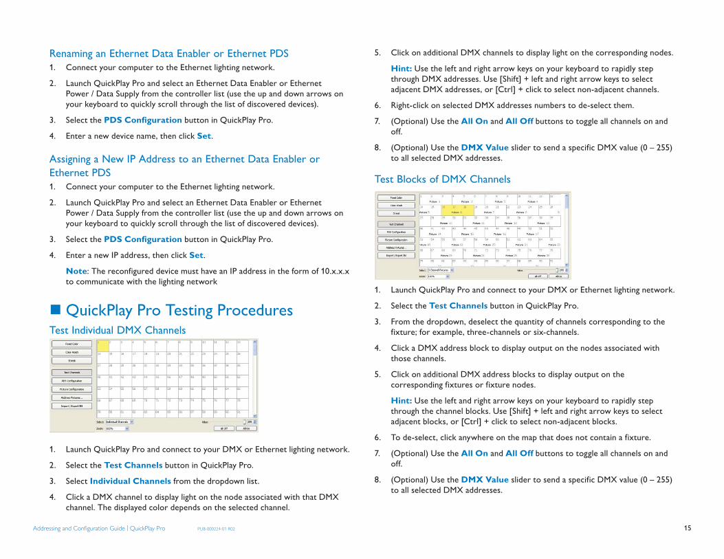
QuickPlay Pro Testing Procedures Test Individual DMX Channels
1. Launch QuickPlay Pro and connect to your DMX or Ethernet lighting network.
2. Select the Test Channels button in QuickPlay Pro.
3. Select Individual Channels from the dropdown list.
4. Click a DMX channel to display light on the node associated with that DMX channel. The displayed color depends on the selected channel.
5. Click on additional DMX channels to display light on the corresponding nodes.
Hint: Use the left and right arrow keys on your keyboard to rapidly step through DMX addresses. Use [Shift] + left and right arrow keys to select adjacent DMX addresses, or [Ctrl] + click to select non-adjacent channels.
6. Right-click on selected DMX addresses numbers to de-select them.
7. (Optional) Use the All On and All Off buttons to toggle all channels on and off.
8. (Optional) Use the DMX Value slider to send a specific DMX value (0 – 255) to all selected DMX addresses.
Test Blocks of DMX Channels
1. Launch QuickPlay Pro and connect to your DMX or Ethernet lighting network.
2. Select the Test Channels button in QuickPlay Pro.
3. From the dropdown, deselect the quantity of channels corresponding to the fixture; for example, three-channels or six-channels.
4. Click a DMX address block to display output on the nodes associated with those channels.
5. Click on additional DMX address blocks to display output on the corresponding fixtures or fixture nodes.
Hint: Use the left and right arrow keys on your keyboard to rapidly step through the channel blocks. Use [Shift] + left and right arrow keys to select adjacent blocks, or [Ctrl] + click to select non-adjacent blocks.
6. To de-select, click anywhere on the map that does not contain a fixture.
7. (Optional) Use the All On and All Off buttons to toggle all channels on and off.
8. (Optional) Use the DMX Value slider to send a specific DMX value (0 – 255) to all selected DMX addresses.

16Addressing and Confi guration Guide | QuickPlay Pro PUB-000224-01 R02
Using the Address Fixtures Tool Add Fixtures to the Fixtures List and DMX Address Map, then Program
The Address Fixture tool allows you to map and program Chromacore fixtures, based on serial numbers:
1. Launch QuickPlay Pro and connect to your DMX or Ethernet lighting network.
2. Select the Address Fixtures button in QuickPlay Pro.
3. Select Add fi xtures to the list... from the dropdown list.
4. Enter the serial number for the first fixture, then press Add.
5. Repeat step 4 for all fixtures, then press OK.
6. Select Add all fi xtures to the map... from the dropdown list.
7. Select and drag fixtures, as desired.
Note: Overlapping fixtures display red arrow icons on the DMX address map. Correct overlapping fixtures, as needed. The black triangle icons in the fixtures list indicate that the fixture(s) require programming.
8. Once the fixture layout is satisfactory, click Program Addresses... to address the fixtures.
9. Click Done.See pages 56–59 for additional details about using the Address Fixtures tool, including the sort fixtures, importing fixtures, and exporting fixtures features.
Using the Import / Export Serial Number Feature
Import Serial Numbers to Automatically Address Fixtures
The Import / Export Serial Number feature enables you to automatically program a series of serial-addressed fixtures, instead of manually entering serial numbers via the Fixture Configuration tool:
1. Create a new document in a spreadsheet program, such as Microsoft Excel.
2. Enter two columns of data: the first column contains each fixture’s serial number, and the second column contains the desired DMX address for each fixture. Alternately, you can enter the DMX address in the first column and fixture serial numbers in the second column.
3. Save the document as a CSV (comma-separated value) file.
Note: The column containing addressing information should contain DMX addresses for each fixture, rather than light numbers.
4. Launch QuickPlay Pro and connect to your DMX or Ethernet lighting network.
5. Select the Import / Export SN button in QuickPlay Pro.
6. Select the Import Serial Numbers button.
7. Browse to the file location, select the file, and select Open.
8. QuickPlay Pro will automatically program all fixtures.
Export Serial Numbers to a CSV FileThe Import / Export SN feature also allows you to save all fixtures programmed with the Fixture Configuration tool to a CSV file:
1. Program fixtures with the Fixture Configuration tool in QuickPlay Pro.

17Addressing and Confi guration Guide | QuickPlay Pro PUB-000224-01 R02
2. Select the Import / Export SN button.
3. Select the Export Serial Numbers button.
4. Enter a file name, then select Save.
Using the QuickPlay Pro Menus
File MenuQuickPlay Pro automatically saves log files of the last 15 sessions to C:\Documents and Settings\<user>\QuickPlayPro\logs\ (Windows®) or /<user>/Library/Logs/QuickPlayPro/Logs/ (Mac OS X). Select Save Log... to manually save a log of the current session under a specific name, to a specific location.
Select Save List of Controllers... to save a CSV file containing the name, IP address (if applicable), and serial number of each device in the controllers list.
Tools MenuSelect Scripting... to open the scripting environment. Scripting is an advanced feature designed for batch fixture processing and custom programming. Contact your Philips Color Kinetics Application Engineering group or technical support team for details on using this feature.
Select Options... to access the Options window.
Options WindowGeneral OptionsRefresh Delay: The light output refresh delay is the amount of time the application waits before sending the next data packet. The delay value is 50 ms, by default. You can reconfigure the delay value using the arrow buttons.
DMX frame size: Select Use selected range to use a DMX channel range less than the full 512 channel universe. This option can reduce data packet size. QuickPlay Pro uses the range specified in the Channels fields.
Sort devices by IP address / serial number: This option changes how the controller list displays discovered devices.
Reset to black when changing controllers: This option sets the previous controller to “black” output whenever you select a new device from the controller list.
Reset QuickPlay Pro: Restore all options back to their default settings.
Network OptionsIf your computer has multiple network adapters, you can select the adapter you wish to use.
UpdatesClick Check Now to determine if a newer version of QuickPlay Pro or iPlayer 3 firmware is available from the web. If a QuickPlay Pro new version is available, click Download Update to load and install. For automatic updating, specify a frequency value and select the Automatically check for updates checkbox.
If your network uses a proxy server, enter the proxy access information before connecting.
Confi guring Fixtures for 16-bit Resolution Certain fixtures from Philips Color Kinetics are configurable as both 8-bit and 16-bit devices. In the Fixture Configuration tool, when you enter a valid 16-bit fixture serial number, or a 16-bit fixture on an Ethernet network is discovered by QuickPlay Pro, the Resolution tab in the Fixture Configuration tool becomes available. In the Resolution tab, select the desired resolution (8-bit or 16-bit) from the dropdown and then click Program. Select Program All to program all compatible discovered fixtures from the same controller with the same resolution setting. Optionally, click Read to query and verify a fixture’s resolution setting.
Note: Fixtures configured for 16-bit mode use double the quantity of DMX addresses compared to 8-bit fixtures.
Note: Only configure fixtures for 16-bit mode if using a 16-bit compatible controller.

18Addressing and Confi guration Guide | QuickPlay Pro PUB-000224-01 R02
Using White Light Systems in DMX or Ethernet-based Environments
Certain IntelliWhite® and EssentialWhite® fixtures from Philips Color Kinetics are compatible with DMX or Ethernet-based environments, provided that the data interface device (Power / Data Supply or Data Enabler) is an RGB unit.
When configured in an RGB environment, IntelliWhite fixtures use the same addressing and configuration methods as RGB fixtures.
When configured in an RGB environment, eW® Flex SLX fixtures also use the same addressing and configuration methods as RGB fixtures. QuickPlay Pro enables you to control individual nodes by setting a base light number and also adjust the brightness of each node.
Working with RDM Fixtures Certain RDM (Remote Device Management) capable fixtures are compatible with lighting systems from Philips Color Kinetics. QuickPlay Pro offers basic RDM functionality via the RDM tab in the Fixture Configuration tool.
When you enter a fixture serial number corresponding to a an RDM fixture, or an RDM fixture on an Ethernet network is discovered by QuickPlay Pro, the RDM tab in the Fixture Configuration tool becomes available. In the RDM tab, select the desired DMX Personality from the dropdown, then click Set.
To access the RDM tab by manually entering a serial number, the serial number must be thirteen characters, with a four-digit RDM prefix separated by a “:”. For example, the following is a valid RDM serial number format: 7353: FD131319.

19Addressing and Confi guration Guide | QuickPlay Pro PUB-000224-01 R02AddAddddressinsingg ag ag ag aa dndndndnd Cononfi gfi gurau tion GGn Guiddu ee || Qu QuickkPlalaPlay Py Py ro PUB-PU 0002224-024-01 R01 R022
Recommended Addressing and Confi guration Methods There are wide-ranging lighting system configurations, each with a specific combination of fixtures and Power / Data Supplies or Data Enablers. To assist with lighting system setup, the following section contains step-by-step addressing, configuration, and testing methods for a wide variety of Philips Color Kinetics lighting system configurations.
Refer to your lighting system user documentation for physical installation instructions. Installation Instructions, User Guides, and Product Guides can be found online at: www.colorkinetics.com/support

20Addressing and Confi guration Guide | QuickPlay Pro PUB-000224-01 R02
ColorBlast® 6 with PDS-150e
Fixture ColorBlast® 6PDS / Data Enabler PDS-150eControl Method DMX or EthernetAddressing Method QuickPlay Pro Fixture Configuration ToolAddressing Technology ChromacoreNodes per fixture 1
OverviewColorBlast 6 fixtures have a single addressable node, which is factory-set to DMX address 1. The QuickPlay Pro Fixture Configuration tool allows you to assign a new DMX address to each ColorBlast 6 based on the fixture’s serial number.
Addressing ColorBlast 6 Fixtures 1. Connect to your DMX or Ethernet lighting network and power on the fixtures you
wish to address.2. Launch QuickPlay Pro.3. Select the Fixture Confi guration button in QuickPlay Pro.4. If known, enter the serial number of the fixture you are addressing. When a valid serial
number has been entered, a green dot appears next to the serial number field. In a DMX configuration, if the serial number is not known, use the serial number Search
feature, which enables you to manually identify the serial number of the connected fixture, one byte at a time:
a. Select the serial number Search tab. Using the up and down arrow keys on your keyboard, scroll through the letters and numerals to identify the first byte of the serial number. When the first byte is found, the fixture (and all other fixtures using that byte) will display solid green.
b. Select the Set checkbox to unlock the second byte. c. Scroll through the letters and numerals to identify the second byte of the serial
number. When the second byte is found, the fixture (and all other fixtures using that byte and previous bytes) will display solid green.
d. Repeat the process until the serial number is complete. In an Ethernet configuration, if the serial number is not known, use the serial number
Discover feature to automatically locate all fixture serial numbers: a. Click Discover. b. Using the up and down arrow keys on your keyboard, select the serial number
of the fixture you wish to address. As you step through the serial numbers, the fixture whose serial number is selected turns green, all others are off.
5. Once the serial number is correctly entered, the Confi guration area becomes active. You can enter a DMX address or light number — select the DMX Address or Light Number tab:
a. In the DMX Address tab, enter a DMX address value in the New DMX Address entry box.
or
b. In the Light Number tab, enter a value in the New Light Number entry box.
6. (Optional) Select the Auto Increment checkbox to automatically advance the DMX address or light number each time you enter a new serial number. This enables you to efficiently and accurately program a series of fixtures.
7. Press Program to address the fixture. “Programming serial number” appears in the status log and the fixture displays green to confirm it has received the new configuration.
(Optional) Testing DMX Channels1. After programming the ColorBlast 6 fixture, select the Test Channels button.2. Select 3 channel fixtures from the dropdown, then select a DMX channel block to
display white light output on the fixture associated with that block.3. Click on additional DMX channel blocks to illuminate the corresponding fixtures. Use
the left and right arrow keys on your keyboard to rapidly step through the blocks. Use [Shift] + left and right arrow keys to keep sequential blocks selected.
4. Right-click on selected DMX channel blocks to de-select them.5. (Optional) Use the All On and All Off buttons to toggle all DMX channel blocks on
and off. Hint: Select Individual Channels from the dropdown list to test individual DMX
channel output.

21Addressing and Confi guration Guide | QuickPlay Pro PUB-000224-01 R02
ColorBlast® 12 with PDS-150e
Fixture ColorBlast® 12PDS / Data Enabler PDS-150eControl Method DMX or EthernetAddressing Method QuickPlay Pro Fixture Configuration ToolAddressing Technology ChromacoreNodes per fixture 1
OverviewColorBlast 12 fixtures have a single addressable node, which is factory-set to DMX address 1. The QuickPlay Pro Fixture Configuration tool allows you to assign a new DMX address to each ColorBlast 12 based on the fixture’s serial number.
Addressing ColorBlast 12 Fixtures 1. Connect to your DMX or Ethernet lighting network and power on the fixtures you
wish to address.2. Launch QuickPlay Pro.3. Select the Fixture Confi guration button in QuickPlay Pro.4. If known, enter the serial number of the fixture you are addressing. When a valid serial
number has been entered, a green dot appears next to the serial number field. In a DMX configuration, if the serial number is not known, use the serial number Search
feature, which enables you to manually identify the serial number of the connected fixture, one byte at a time:
a. Select the serial number Search tab. Using the up and down arrow keys on your keyboard, scroll through the letters and numerals to identify the first byte of the serial number. When the first byte is found, the fixture (and all other fixtures using that byte) will display solid green.
b. Select the Set checkbox to unlock the second byte. c. Scroll through the letters and numerals to identify the second byte of the serial
number. When the second byte is found, the fixture (and all other fixtures using that byte and previous bytes) will display solid green.
d. Repeat the process until the serial number is complete. In an Ethernet configuration, if the serial number is not known, use the serial number
Discover feature to automatically locate all fixture serial numbers: a. Click Discover b. Using the up and down arrow keys on your keyboard, select the serial number
of the fixture you wish to address. As you step through the serial numbers, the fixture whose serial number is selected turns green, all others are off.
5. Once the serial number is correctly entered, the Confi guration area becomes active. You can enter a DMX address or light number — select the DMX Address or Light Number tab:
a. In the DMX Address tab, enter a DMX address value in the New DMX Address entry box.
or
b. In the Light Number tab, enter a value in the New Light Number entry box.
6. (Optional) Select the Auto Increment checkbox to automatically advance the DMX address or light number each time you enter a new serial number. This enables you to efficiently and accurately program a series of fixtures.
7. Press Program to address the fixture. “Programming serial number” appears in the status log and the fixture displays green to confirm it has received the new configuration.
(Optional) Testing DMX Channels1. After programming the ColorBlast 12 fixture, select the Test Channels button.2. Select 3 channel fixtures from the dropdown, then select a DMX channel block to
display white light output on the fixture associated with that block.3. Click on additional DMX channel blocks to illuminate the corresponding fixtures. Use
the left and right arrow keys on your keyboard to rapidly step through the blocks. Use [Shift] + left and right arrow keys to keep sequential blocks selected.
4. Right-click on selected DMX channel blocks to de-select them.5. (Optional) Use the All On and All Off buttons to toggle all DMX channel blocks on
and off. Hint: Select Individual Channels from the dropdown list to test individual DMX
channel output.

22Addressing and Confi guration Guide | QuickPlay Pro PUB-000224-01 R02
ColorBlast® Powercore with Data Enabler DMX
Fixture ColorBlast® PowercorePDS / Data Enabler Data Enabler DMXControl Method DMXAddressing Method QuickPlay Pro Fixture Configuration ToolAddressing Technology ChromacoreNodes per fixture 1
OverviewColorBlast Powercore fixtures have a single addressable node, which is factory-set to DMX address 1. The QuickPlay Pro Fixture Configuration tool allows you to assign a new DMX address to each ColorBlast Powercore based on the fixture’s serial number.
Addressing ColorBlast Powercore Fixtures1. Connect your lighting network to SmartJack Pro or iPlayer 3, then power on the
fixtures you wish to address.2. Connect SmartJack Pro or iPlayer 3 to your computer via USB, then launch QuickPlay
Pro.3. Select the Fixture Confi guration button in QuickPlay Pro.4. If known, enter the serial number of the fixture you are addressing. When a valid
serial number has been entered, a green dot appears next to the serial number field. Otherwise, use the QuickPlay Pro serial number Search feature, which enables you to manually identify the serial number of the connected fixture, one byte at a time:
a. Select the serial number Search tab. Using the up and down arrow keys on your keyboard, scroll through the letters and numerals to identify the first byte of the serial number. When the first byte is found, the fixture (and all other fixtures using that byte) will display solid green.
b. Select the Set checkbox to unlock the second byte. c. Scroll through the letters and numerals to identify the second byte of the serial
number. When the second byte is found, the fixture (and all other fixtures using that byte and previous bytes) will display solid green.
d. Repeat the process until the serial number is complete.
5. Once the serial number is correctly entered, the Confi guration area becomes active. You can enter a DMX address or light number — select the DMX Address or Light Number tab:
a. In the DMX Address tab, enter a DMX address value in the New DMX Address entry box.
or
b. In the Light Number tab, enter a value in the New Light Number entry box.
6. (Optional) Select the Auto Increment checkbox to automatically advance the DMX address or light number each time you enter a new serial number. This enables you to efficiently and accurately program a series of fixtures.
7. Press Program to address the fixture. “Programming serial number” appears in the status log and the fixture displays green to confirm it has received the new configuration.
(Optional) Testing DMX Channels1. After programming the ColorBlast Powercore fixture, select the Test Channels
button.2. Select 3 channel fixtures from the dropdown, then select a DMX channel block to
display white light output on the fixture associated with that block.3. Click on additional DMX channel blocks to illuminate the corresponding fixtures. Use
the left and right arrow keys on your keyboard to rapidly step through the blocks. Use [Shift] + left and right arrow keys to keep sequential blocks selected.
4. Right-click on selected DMX channel blocks to de-select them.5. (Optional) Use the All On and All Off buttons to toggle all DMX channel blocks on
and off. Hint: Select Individual Channels from the dropdown list to test individual DMX
channel output.

23Addressing and Confi guration Guide | QuickPlay Pro PUB-000224-01 R02
ColorBlast® Powercore with Data Enabler Ethernet
Fixture ColorBlast® PowercorePDS / Data Enabler Data Enabler EthernetControl Method EthernetAddressing Method QuickPlay Pro Fixture Configuration ToolAddressing Technology ChromacoreNodes per fixture 1
OverviewColorBlast Powercore fixtures have a single addressable node. The QuickPlay Pro Fixture Configuration tool allows you to assign a light number to each ColorBlast Powercore based on the fixture’s serial number. QuickPlay Pro connects directly to the Ethernet lighting network.
Addressing ColorBlast Powercore Fixtures1. Connect to your lighting network via Ethernet and power on the fixtures you wish
to address.2. Using the up and down arrow keys on your keyboard, select the appropriate
Data Enabler from the controller list. As you step through the Data Enablers, the corresponding fixtures display green, the currently playing effect, or, if in test mode, the selected light numbers or DMX addresses.
3. Select the Fixture Confi guration button in QuickPlay Pro.4. Click Discover to automatically locate all fixture serial numbers.5. Using the up and down arrow keys on your keyboard, select the serial number of the
fixture you wish to address. As you step through the serial numbers, the fixture whose serial number is selected turns green, all others are off.
6. If not already open, click the DMX address tab.7. (Optional) Click Read to discover the current DMX address.8. Enter a new DMX address.9. (Optional) Select the Auto Increment checkbox to automatically increment the
DMX addresses as fixture serial numbers are selected.10. Press Program to address the fixture. “Programming serial number” appears in
the status log and the fixture displays green to confirm it has received the new configuration.
(Optional) Testing DMX Channels1. After programming the ColorBlast Powercore fixture, select the Test Channels
button.2. Select 3 channel fixtures from the dropdown, then select a DMX channel block to
display white light output on the fixture associated with that block.3. Click on additional DMX channel blocks to illuminate the corresponding fixtures. Use
the left and right arrow keys on your keyboard to rapidly step through the blocks. Use [Shift] + left and right arrow keys to keep sequential blocks selected.
4. Right-click on selected DMX channel blocks to de-select them.5. (Optional) Use the All On and All Off buttons to toggle all DMX channel blocks on
and off. Hint: Select Individual Channels from the dropdown list to test individual DMX
channel output.

24Addressing and Confi guration Guide | QuickPlay Pro PUB-000224-01 R02
ColorBlast® TR with PDS-750 TR
Fixture ColorBlast® TRPDS / Data Enabler PDS-750 TRControl Method DMXAddressing Method Onboard PDS Address SwitchesAddressing Technology ChromacoreNodes per fixture 1
OverviewPDS-750 TR Power / Data Supplies have onboard addressing controls — an external software tool such as QuickPlay Pro is not necessary to configure fixtures connected to a PDS-750 TR.
Each PDS-750 TR supports up to 12 ColorBlast TR fixtures. Using a base DMX address, the PDS-750 TR sequentially routes DMX data to each connected fixture. For example, if “AAA” equals the base DMX address configured on the PDS-750 TR, the connected fixtures receive DMX data as follows:
Fixture #1 receives data intended for DMX addresses: AAA, AAA + 1, AAA + 2• Fixture #2 receives data intended for DMX • addresses: AAA + 3, AAA + 4, AAA + 5Fixture #3 receives data intended for DMX • addresses: AAA + 6, AAA + 7, AAA + 8
To function properly when connected to a PDS-750 TR, all ColorBlast TR fixtures must be addressed to a DMX address of 1.
Addressing ColorBlast TR Fixtures to DMX address 11. Power On the PDS-750 TR and select Pass Thru mode by turning all three DMX
switches to 0 (the “Status” light displays orange when the device is in Pass Thru mode).2. Connect up to 12 ColorBlast TR fixtures to the PDS-750 TR.3 Press the Mini-Zapi switch on the front of the PDS-750 TR.4. The fixtures will momentarily display red and then flicker.5. When the flickering stops, power Off the PDS-750 TR.6. Power back On the PDS-750 TR, to resume operation.
Addressing the PDS-750 TR with a Base DMX Address1. Power On the PDS-750 TR.2. Connect up to 12 ColorBlast TR fixtures to ports 1 – 12 (all fixtures must be
addressed to light number 1).3. Connect the PDS-750 TR to a DMX source via the DMX Input port.4. Set the base DMX address of the PDS-750 TR using the DMX switches: From left to right, the switches control the 100s, 10s, and 1s DMX values. For
example, to set a base DMX address of 125, turn the first switch to 1, the second switch to 2, and the third switch to 5.
When you have set a base DMX address, the status light should display green, indicating that the PDS-750 TR is in CB (ColorBlast playback) mode.
5. Test your configuration by sending light output data from the DMX controller.
Standalone Effects modeStandalone Effects mode allows you to run pre-programmed effects from the PDS-750 TR, for demonstration purposes. To launch Standalone Effects mode, turn the Config switch to any setting other than 0:
Config Switch Setting
Effect
0 Standalone Effect Mode is Off.
1Fixed Color: Use the DMX switches to set the color: the left DMX switch controls the red value, the center switch controls the green value, and the right switch controls the blue value (0 is Off and 9 equals full output).
2Color Wash (forward): This effect moves sequentially through the color spectrum. Use the center and right DMX controls to adjust the effect duration (the greater the number, the longer the effect).
3 Color Wash (backward): Same as above, but in the opposite direction through the color spectrum.
4Cross-Fade: Colors change from one preset color to another, then back again. The left DMX switch sets the starting color, the center switch sets the end color, and the right switch adjusts duration.
5 Random Color: Colors are generated at random. Use the center and right DMX switches to adjust the effect duration.
6Fixed Color Strobe: Generates pulsating color. The left DMX switch determines the color (1-red, 2-green, 3-yellow, 4-blue, 5-magenta, 6-cyan, 7-white, 8 & 9-black). The right DMX switch adjusts the strobe rate.
7Variable Color Strobe: Generates a strobe that steps from color to color. The left and center DMX switches set the step times between colors. The right DMX switch adjusts the strobe rate.
Note: The latest PDS-750 TR operator’s manual is available from the City Theatrical, Inc. website (a third-party website), under the Color Kinetics tab: www.citytheatrical.com/.

25Addressing and Confi guration Guide | QuickPlay Pro PUB-000224-01 R02
ColorBlaze®
Fixture ColorBlaze® 48 and ColorBlaze® 72PDS / Data Enabler OnboardControl Method DMXAddressing Method Onboard AddressingAddressing Technology ChromacoreNodes per fixture 1 – 12
OverviewColorBlaze fixtures have built-in power supplies and onboard addressing controls — an external software tool such as QuickPlay Pro is not necessary to perform setup.
ColorBlaze fixtures have individually addressable LED segments. You can change the number of segments to suit your installation needs: 1, 2, 4, or 8 segments for ColorBlaze 48; and 1, 2, 3, 4, 6, or 12 segments for ColorBlaze 72.
To configure the segment quantity, you specify groups. For example, setting a ColorBlaze 48 to 4 groups results in 4 segments of LEDs approximately 1 ft (304 mm) each. Setting a ColorBlaze 72 to 3 groups results in 3 segments of LEDs approximately 2 ft (610 mm) each.
Segment Length ColorBlaze 48 Groups ColorBlaze 72 Groups6 ft — 14 ft 1 —3 ft — 22 ft 2 31.5 ft — 41 ft 4 6.5 ft A (8) A (12)
Every ColorBlaze fixture is factory-addressed with a segment quantity of 4 and a DMX address of 1. To re-configure a ColorBlaze fixture, you first specify the group quantity to set segments, and then configure a DMX address. The onboard controls then automatically assign sequential DMX addresses to each LED segment.
Make sure that the DMX address allows enough DMX addresses for all of the fixture’s segments, or the fixture will not function properly. For example, a fixture with 4 segments require 12 DMX addresses, 3 per segment. Therefore, the DMX address should be 501 or lower.
Set ColorBlaze Segment Quantity1. In the Number of Groups panel on the back of the fixture housing, press the [+] and [-]
buttons to scroll through the options: ▪ Select from 1, 2, 4, or A (8) for ColorBlaze 48. ▪ Select from 1, 2, 3, 4, 6, or (12) for ColorBlaze 72.2. Record each fixture’s settings on your lighting design plan or in a spreadsheet.
Set DMX Address
According to the DMX address, onboard addressing automatically assigns consecutive DMX addresses to the fixture’s segments (from left to right, when facing the back of the fixture).1. In the DMX Address area on the back of the fixture housing, press the [+] and [-]
buttons to scroll through all available DMX addresses (1 — 512).
DMX Address Example, by Segment
Segment 1DMX 1
Segment 1DMX 1
Segment 2DMX 4
Segment 1DMX 1
Segment 2DMX 4
Segment 3DMX 7
Segment 4DMX 10
Segment 1DMX 1
Segment 2DMX 4
Segment 3DMX 7
Segment 4DMX 10
Segment 5DMX 13
Segment 6DMX 16
Segment 7DMX 19
Segment 8DMX 22
Example: ColorBlaze 48 (DMX Address 1)
DMX Address Example, by Segment
Segment 1DMX 1
Segment 1DMX 1
Segment 2DMX 4
Segment 1DMX 1
Segment 2DMX 4
Segment 3DMX 7
Segment 1DMX 1
Segment 2DMX 4
Segment 3DMX 7
Segment 4DMX 10
Segment 1DMX 1
Segment 2DMX 4
Segment 3DMX 7
Segment 4DMX 10
Segment 5DMX 13
Segment 6DMX 16
Seg 11
Seg 24
Seg 37
Seg 410
Seg 513
Seg 616
Seg 719
Seg 822
Seg 925
Seg 1028
Seg 1131
Seg 1234
Example: ColorBlaze 72 (DMX Address 1)

26Addressing and Confi guration Guide | QuickPlay Pro PUB-000224-01 R02
ColorBurst® 6 with PDS-150e
Fixture ColorBurst® 6PDS / Data Enabler PDS-150eControl Method DMX or EthernetAddressing Method QuickPlay Pro Fixture Configuration ToolAddressing Technology ChromacoreNodes per fixture 1
OverviewColorBurst 6 fixtures have a single addressable node, which is factory-set to DMX address 1. The QuickPlay Pro Fixture Configuration tool allows you to assign a new DMX address to each ColorBurst 6 based on the fixture’s serial number.
Addressing ColorBurst 6 Fixtures1. Connect to your DMX or Ethernet lighting network and power on the fixtures you
wish to address.2. Launch QuickPlay Pro.3. Select the Fixture Confi guration button in QuickPlay Pro.4. If known, enter the serial number of the fixture you are addressing. When a valid serial
number has been entered, a green dot appears next to the serial number field. In a DMX configuration, if the serial number is not known, use the serial number Search
feature, which enables you to manually identify the serial number of the connected fixture, one byte at a time:
a. Select the serial number Search tab. Using the up and down arrow keys on your keyboard, scroll through the letters and numerals to identify the first byte of the serial number. When the first byte is found, the fixture (and all other fixtures using that byte) will display solid green.
b. Select the Set checkbox to unlock the second byte. c. Scroll through the letters and numerals to identify the second byte of the serial
number. When the second byte is found, the fixture (and all other fixtures using that byte and previous bytes) will display solid green.
d. Repeat the process until the serial number is complete.
In an Ethernet configuration, if the serial number is not known, use the serial number Discover feature to automatically locate all fixture serial numbers:
a. Click Discover. b. Using the up and down arrow keys on your keyboard, select the serial number
of the fixture you wish to address. As you step through the serial numbers, the fixture whose serial number is selected turns green, all others are off.
5. Once the serial number is correctly entered, the Confi guration area becomes active. You can enter a DMX address or light number — select the DMX Address or Light Number tab:
a. In the DMX Address tab, enter a DMX address value in the New DMX Address entry box.
or
b. In the Light Number tab, enter a value in the New Light Number entry box.
6. (Optional) Select the Auto Increment checkbox to automatically advance the DMX address or light number each time you enter a new serial number. This enables you to efficiently and accurately program a series of fixtures.
7. Press Program to address the fixture. “Programming serial number” appears in the status log and the fixture displays green to confirm it has received the new configuration.
(Optional) Testing DMX Channels1. After programming the ColorBurst 6 fixture, select the Test Channels button.2. Select 3 channel fixtures from the dropdown, then select a DMX channel block to
display white light output on the fixture associated with that block.3. Click on additional DMX channel blocks to illuminate the corresponding fixtures. Use
the left and right arrow keys on your keyboard to rapidly step through the blocks. Use [Shift] + left and right arrow keys to keep sequential blocks selected.
4. Right-click on selected DMX channel blocks to de-select them.5. (Optional) Use the All On and All Off buttons to toggle all DMX channel blocks on
and off. Hint: Select Individual Channels from the dropdown list to test individual DMX
channel output.

27Addressing and Confi guration Guide | QuickPlay Pro PUB-000224-01 R02
ColorGraze™ Powercore withData Enabler DMX
Fixture ColorGraze™ PowercorePDS / Data Enabler Data Enabler DMX Control Method DMXAddressing Method QuickPlay Pro Fixture Configuration ToolAddressing Technology ChromacoreNodes per fixture 2 - 4
OverviewColorGraze Powercore fixtures have 2 – 4 segments of addressable nodes, depending on fixture housing length. By default, all ColorGraze Powercore segments are factory-set to DMX address 1. QuickPlay Pro enables you to re-program each segment with a new DMX address, linking the DMX address to the hard-coded serial number for that segment. QuickPlay Pro connects to the DMX lighting network via a SmartJack Pro or iPlayer 3Addressing ColorGraze Powercore Fixtures1. Connect your lighting network to SmartJack Pro or iPlayer 3, then power on the
fixtures you wish to address.2. Connect SmartJack Pro or iPlayer 3 to your computer via USB, then launch QuickPlay
Pro.3. Select the Fixture Confi guration button in QuickPlay Pro.4. If known, enter the serial number of the fixture you are addressing. When a valid
serial number has been entered, a green dot appears next to the serial number field. Otherwise, use the QuickPlay Pro serial number Search feature, which enables you to manually identify the serial number of a connected segment, one byte at a time:
a. Select the serial number Search tab. Using the up and down arrow keys on your keyboard, scroll through the letters and numerals to identify the first byte of the serial number. When the first byte is found, the fixture (and all other fixtures using that byte) will display solid green.
b. Select the Set checkbox to unlock the second byte. c. Scroll through the letters and numerals to identify the second byte of the serial
number. When the second byte is found, the fixture (and all other fixtures using that byte and previous bytes) will display solid green.
d. Repeat the process until the serial number is complete.
5. Once the serial number is correctly entered, the Confi guration area becomes active. You can enter a DMX address or light number — select the DMX Address or Light Number tab:
a. In the DMX Address tab, enter a DMX address value in the New DMX Address entry box.
or
b. In the Light Number tab, enter a value in the New Light Number entry box.
6. (Optional) Select the Auto Increment checkbox to automatically advance the DMX address or light number each time you enter a new serial number. This enables you to efficiently and accurately program a series of fixtures.
7. Press Program to address the fixture. “Programming serial number” appears in the status log and the fixture displays green to confirm it has received the new configuration.
8. (Optional) In the Resolution tab, select 16-bit from the dropdown menu to toggle from the default resolution (8-bit).
Note: Increasing the resolution enhances dimming performance but doubles the quantity of DMX addresses used per fixture.
Note: Only select the 16-bit option if you are using a 16-bit compatible controller.9. Repeat steps 4 – 8 for each segment in the fixture.
(Optional) Testing DMX Channels1. After programming the ColorGraze Powercore fixture, select the Test Channels
button.2. Select 3 channel fixtures from the dropdown, then select a DMX channel block to
display white light output on the fixture associated with that block.3. Click on additional DMX channel blocks to illuminate the corresponding fixtures. Use
the left and right arrow keys on your keyboard to rapidly step through the blocks. Use [Shift] + left and right arrow keys to keep sequential blocks selected.
4. Right-click on selected DMX channel blocks to de-select them.5. (Optional) Use the All On and All Off buttons to toggle all DMX channel blocks on
and off. Hint: Select Individual Channels from the dropdown list to test individual DMX
channel output.
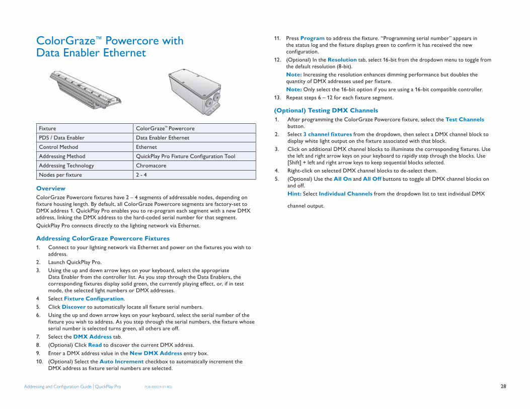
28Addressing and Confi guration Guide | QuickPlay Pro PUB-000224-01 R02
ColorGraze™ Powercore with Data Enabler Ethernet
Fixture ColorGraze™ PowercorePDS / Data Enabler Data Enabler Ethernet Control Method EthernetAddressing Method QuickPlay Pro Fixture Configuration ToolAddressing Technology ChromacoreNodes per fixture 2 - 4
OverviewColorGraze Powercore fixtures have 2 – 4 segments of addressable nodes, depending on fixture housing length. By default, all ColorGraze Powercore segments are factory-set to DMX address 1. QuickPlay Pro enables you to re-program each segment with a new DMX address, linking the DMX address to the hard-coded serial number for that segment. QuickPlay Pro connects directly to the lighting network via Ethernet.
Addressing ColorGraze Powercore Fixtures1. Connect to your lighting network via Ethernet and power on the fixtures you wish to
address.2. Launch QuickPlay Pro.3. Using the up and down arrow keys on your keyboard, select the appropriate
Data Enabler from the controller list. As you step through the Data Enablers, the corresponding fixtures display solid green, the currently playing effect, or, if in test mode, the selected light numbers or DMX addresses.
4 Select Fixture Confi guration.5. Click Discover to automatically locate all fixture serial numbers.6. Using the up and down arrow keys on your keyboard, select the serial number of the
fixture you wish to address. As you step through the serial numbers, the fixture whose serial number is selected turns green, all others are off.
7. Select the DMX Address tab.8. (Optional) Click Read to discover the current DMX address.9. Enter a DMX address value in the New DMX Address entry box. 10. (Optional) Select the Auto Increment checkbox to automatically increment the
DMX address as fixture serial numbers are selected.
11. Press Program to address the fixture. “Programming serial number” appears in the status log and the fixture displays green to confirm it has received the new configuration.
12. (Optional) In the Resolution tab, select 16-bit from the dropdown menu to toggle from the default resolution (8-bit).
Note: Increasing the resolution enhances dimming performance but doubles the quantity of DMX addresses used per fixture.
Note: Only select the 16-bit option if you are using a 16-bit compatible controller.13. Repeat steps 6 – 12 for each fixture segment.
(Optional) Testing DMX Channels1. After programming the ColorGraze Powercore fixture, select the Test Channels
button.2. Select 3 channel fixtures from the dropdown, then select a DMX channel block to
display white light output on the fixture associated with that block.3. Click on additional DMX channel blocks to illuminate the corresponding fixtures. Use
the left and right arrow keys on your keyboard to rapidly step through the blocks. Use [Shift] + left and right arrow keys to keep sequential blocks selected.
4. Right-click on selected DMX channel blocks to de-select them.5. (Optional) Use the All On and All Off buttons to toggle all DMX channel blocks on
and off. Hint: Select Individual Channels from the dropdown list to test individual DMX
channel output.

29Addressing and Confi guration Guide | QuickPlay Pro PUB-000224-01 R02
ColorReach™ Powercore with Data Enabler DMX
Fixture ColorReach™ PowercorePDS / Data Enabler Data Enabler DMXControl Method DMXAddressing Method QuickPlay Pro Fixture Configuration ToolAddressing Technology ChromacoreNodes per fixture 1 or 2
OverviewColorReach Powercore fixtures have one or two addressable segments. The QuickPlay Pro Fixture Configuration tool allows you to assign “full fixture” mode control (to treat the fixture as one segment) or “half fixture” mode control (to treat the fixture as two individually controllable segments) based on a single serial number.
Addressing ColorReach Powercore Fixtures1. Connect your lighting network to SmartJack Pro or iPlayer 3, then power on the
fixtures you wish to address.2. Connect SmartJack Pro or iPlayer 3 to your computer via USB, then launch QuickPlay
Pro.3. Select the Fixture Confi guration button in QuickPlay Pro.4. If known, enter the serial number of the fixture you are addressing. When a valid
serial number has been entered, a green dot appears next to the serial number field. Otherwise, use the QuickPlay Pro serial number Search feature, which enables you to manually identify the serial number of a connected fixture, one byte at a time:
a. Select the serial number Search tab. Using the up and down arrow keys on your keyboard, scroll through the letters and numerals to identify the first byte of the serial number. When the first byte is found, the fixture (and all other fixtures using that byte) will display solid green.
b. Select the Set checkbox to unlock the second byte.c. Scroll through the letters and numerals to identify the second byte of the serial
number. When the second byte is found, the fixture (and all other fixtures using that byte and previous bytes) will display solid green.
d. Repeat the process until the serial number is complete.
The Confi guration panel becomes active once a valid serial number is entered.5. (Optional) In the Mode tab, enter the desired fixture mode (Full Fixture, or Half
Fixture to create two addressable segments within the fixture). Note: Half fixture mode doubles the quantity of DMX addresses used per fixture.6. (Optional) In the Resolution tab, select 16-bit from the dropdown menu to toggle from
the default 8-bit resolution. Note: Increasing the resolution enhances dimming performance but doubles the
quantity of DMX addresses used per fixture. Note: Only select the 16-bit option if you are using a 16-bit compatible controller.7. In the DMX Address tab, enter a DMX address value in the New DMX
Address entry box.8. (Optional) Select the Auto Increment checkbox to automatically advance the DMX
address each time you enter a new serial number. This enables you to efficiently and accurately program a series of fixtures.
9. Press Program to address the fixture. “Programming serial number” appears in the status log and the fixture displays green to confirm it has received the new configuration.
(Optional) Testing DMX Channels1. After programming the ColorReach Powercore fixture, select the Test Channels
button.2. Select 3 channel fixtures from the dropdown, then select a DMX channel block to
display white light output on the fixture associated with that block.3. Click on additional DMX channel blocks to illuminate the corresponding fixtures. Use
the left and right arrow keys on your keyboard to rapidly step through the blocks. Use [Shift] + left and right arrow keys to keep sequential blocks selected.
4. Right-click on selected DMX channel blocks to de-select them.5. (Optional) Use the All On and All Off buttons to toggle all DMX channel blocks on
and off. Hint: Select Individual Channels from the dropdown list to test individual DMX
channel output.

30Addressing and Confi guration Guide | QuickPlay Pro PUB-000224-01 R02
ColorReach™ Powercore with Data Enabler Ethernet
Fixture ColorReach™ PowercorePDS / Data Enabler Data Enabler EthernetControl Method EthernetAddressing Method QuickPlay Pro Fixture Configuration ToolAddressing Technology ChromacoreNodes per fixture 1 or 2
OverviewColorReach Powercore fixtures have one or two addressable segments. The QuickPlay Pro Fixture Configuration tool allows you to assign “full fixture” control (to treat the fixture as one segment) or “half fixture” control (to treat the fixture as two individually controllable segments) based on a single serial number.QuickPlay Pro connects directly to the Ethernet lighting network.
Addressing ColorReach Powercore Fixtures1. Connect to your lighting network via Ethernet and power on the fixtures you wish to
address.2. Launch QuickPlay Pro.3. Using the up and down arrow keys on your keyboard, select the appropriate
Data Enabler from the controller list. As you step through the Data Enablers, the corresponding fixtures display solid green, the currently playing effect, or, if in test mode, the selected light numbers or DMX addresses.
4. Select Fixture Confi guration.5. Click Discover to automatically locate all fixture serial numbers.6. Using the up and down arrow keys on your keyboard, select the serial number of the
fixture you wish to address. As you step through the serial numbers, the fixture whose serial number is selected turns green, all others are off.
7. (Optional) In the Mode tab, enter the desired fixture mode (Full Fixture, or Half Fixture to create two addressable segments within the fixture).
Note: Half fixture mode doubles the quantity of DMX addresses used per fixture.
8. (Optional) In the Resolution tab, select 16-bit from the dropdown menu to toggle from the default 8-bit resolution.
Note: Increasing the resolution enhances dimming performance but doubles the quantity of DMX addresses used per fixture.
Note: Only select the 16-bit option if you are using a 16-bit compatible controller.9. In the DMX Address tab, enter a DMX address value in the New DMX
Address entry box.10. (Optional) Select the Auto Increment checkbox to automatically advance the DMX
address each time you enter a new serial number. This enables you to efficiently and accurately program a series of fixtures.
11. Press Program to address the fixture. “Programming serial number” appears in the status log and the fixture displays green to confirm it has received the new configuration..
(Optional) Testing DMX Channels1. After programming the ColorReach Powercore fixture, select the Test Channels
button.2. Select 3 channel fixtures from the dropdown, then select a DMX channel block to
display white light output on the fixture associated with that block.3. Click on additional DMX channel blocks to illuminate the corresponding fixtures. Use
the left and right arrow keys on your keyboard to rapidly step through the blocks. Use [Shift] + left and right arrow keys to keep sequential blocks selected.
4. Right-click on selected DMX channel blocks to de-select them.5. (Optional) Use the All On and All Off buttons to toggle all DMX channel blocks on
and off. Hint: Select Individual Channels from the dropdown list to test individual DMX
channel output.

31Addressing and Confi guration Guide | QuickPlay Pro PUB-000224-01 R02
C-Splash 2™ with PDS-150e
Fixture C-Splash 2PDS / Data Enabler PDS-150eControl Method DMX or EthernetAddressing Method QuickPlay Pro Fixture Configuration ToolAddressing Technology ChromacoreNodes per fixture 1
OverviewC-Splash 2 fixtures have a single addressable node, which is factory-set to DMX address 1. The QuickPlay Pro Fixture Configuration tool allows you to assign a new DMX address to each C-Splash 2 based on the fixture’s serial number.
Addressing C-Splash 2 Fixtures1. Connect to your DMX or Ethernet lighting network and power on the fixtures you
wish to address.2. Launch QuickPlay Pro.3. Select the Fixture Confi guration button in QuickPlay Pro.4. If known, enter the serial number of the fixture you are addressing. When a valid serial
number has been entered, a green dot appears next to the serial number field. In a DMX configuration, if the serial number is not known, use the serial number Search
feature, which enables you to manually identify the serial number of the connected fixture, one byte at a time:
a. Select the serial number Search tab. Using the up and down arrow keys on your keyboard, scroll through the letters and numerals to identify the first byte of the serial number. When the first byte is found, the fixture (and all other fixtures using that byte) will display solid green.
b. Select the Set checkbox to unlock the second byte. c. Scroll through the letters and numerals to identify the second byte of the serial
number. When the second byte is found, the fixture (and all other fixtures using that byte and previous bytes) will display solid green.
d. Repeat the process until the serial number is complete.
In an Ethernet configuration, if the serial number is not known, use the serial number Discover feature to automatically locate all fixture serial numbers:
a. Click Discover b. Using the up and down arrow keys on your keyboard, select the serial number
of the fixture you wish to address. As you step through the serial numbers, the fixture whose serial number is selected turns green, all others are off.
5. Once the serial number is correctly entered, the Confi guration area becomes active. You can enter a DMX address or light number — select the DMX Address or Light Number tab:
a. In the DMX Address tab, enter a DMX address value in the New DMX Address entry box.
or
b. In the Light Number tab, enter a value in the New Light Number entry box.
6. (Optional) Select the Auto Increment checkbox to automatically advance the DMX address or light number each time you enter a new serial number. This enables you to efficiently and accurately program a series of fixtures.
7. Press Program to address the fixture. “Programming serial number” appears in the status log and the fixture displays green to confirm it has received the new configuration.
(Optional) Testing DMX Channels1. After programming the C-Splash 2 fixture, select the Test Channels button.2. Select 3 channel fixtures from the dropdown, then select a DMX channel block to
display white light output on the fixture associated with that block.3. Click on additional DMX channel blocks to illuminate the corresponding fixtures. Use
the left and right arrow keys on your keyboard to rapidly step through the blocks. Use [Shift] + left and right arrow keys to keep sequential blocks selected.
4. Right-click on selected DMX channel blocks to de-select them.5. (Optional) Use the All On and All Off buttons to toggle all DMX channel blocks on
and off. Hint: Select Individual Channels from the dropdown list to test individual DMX
channel output.

32Addressing and Confi guration Guide | QuickPlay Pro PUB-000224-01 R02
eW® Flex SLX with PDS-60ca 24V DMX
Fixture eW® Flex SLXPDS / Data Enabler PDS-60ca 24V DMXControl Method DMXAddressing Method QuickPlay Pro PDS Configuration ToolAddressing Technology ChromasicNodes per fixture 50
OverviewWhen connected to a PDS-60ca, eW Flex SLX white light fixtures are compatible with DMX controllers. Installing eW Flex SLX fixtures in a DMX lighting network enables fine control of node brightness and integration with color-changing fixtures.
To program a PDS-60ca, you use QuickPlay Pro to set a base light number (1 – 170) and specify the node quantity of each attached fixture. The Power / Data Supply then configures itself to route the correct data to the attached fixtures, beginning with the first node on output port 1 and ending with the last node on output port 2.
Note that eW Flex SLX fixtures are not programmed with light numbers. Instead the Power / Data Supply receives a base light number, which it uses to capture and automatically route the correct data to each node in the attached fixtures. Therefore, you can swap the eW Flex SLX fixtures attached to a PDS-60ca and the newly attached fixtures will always display the correct data.
Addressing a PDS-60ca Connected to eW Flex SLX Fixtures 1. Connect the PDS-60ca directly to SmartJack Pro or iPlayer 3. Disconnect all other
Power / Data Supplies in the network.2. Connect SmartJack Pro or iPlayer 3 to your computer via USB, then launch QuickPlay
Pro. 3. (Optional, for iPlayer 3) Select a specific output port, or select All to send the same
light data to all output ports.4. Select the PDS Confi guration button.5. Select the correct tab for your Power / Data Supply, PDS-60ca DMX or PDS-60ca
DMX / Ethernet.
6. By default, QuickPlay Pro enters the maximum node count for each port (72) in the Node Count for Output 1 or Node Count for Output 2 fields. Determine the node counts of your fixtures and enter the values in the Node Count for Output 1 and Node Count for Output 2 fields.
7. Enter the desired DMX address in the Base Light Number field.8. There are two options for configuring how the Power / Data Supply routes data to the
fixtures, sequential addressing and all same address: Sequential Addressing a. Leave the All Same Address box unchecked. b. Click Program. The base address is the light number associated with the first
node on OUT 1. The remaining nodes are associated with light numbers in sequential order through the last node on OUT 2. Fixtures display green when programming is complete.
Set All Fixtures to the Same Light Number a. Check the All Same Address box. b. Click Program. The base address determines the light number associated with
all of the nodes on OUT 1 and OUT 2. Fixtures display green when programming is complete.
(Optional) Testing DMX Channels1. After programming the eW Flex SLX fixture, select the Test Channels button.2. Select 3 channel fixtures from the dropdown, then select a DMX channel block to
display white light output on the fixture associated with that block.3. Click on additional DMX channel blocks to illuminate the corresponding fixtures. Use
the left and right arrow keys on your keyboard to rapidly step through the blocks. Use [Shift] + left and right arrow keys to keep sequential blocks selected.
4. Right-click on selected DMX channel blocks to de-select them.5. (Optional) Use the All On and All Off buttons to toggle all DMX channel blocks on
and off.

33Addressing and Confi guration Guide | QuickPlay Pro PUB-000224-01 R02
iColor® Accent Powercore with Data Enabler EO
Fixture iColor® Accent PowercorePDS / Data Enabler Data Enabler EO Control Method DMX or EthernetAddressing Method QuickPlay Pro PDS Configuration ToolAddressing Technology ChromasicPixels per fixture Adjustable
OverviewiColor Accent Powercore fixtures have adjustable pixel resolution, allowing you to change the effective size of the pixels in each fixture, in 1.2 in (30 mm) increments. For example, using QuickPlay Pro, you can program a two-foot iColor Accent Powercore fixture with from 1 to 20 addressable pixels.
iColor Accent Powercore fixtures are factory-set to a pixel resolution of 1, or 10 pixels per foot. To achieve consistent pixel sizing across fixtures, use a pixel resolution that divides evenly into the fixture length:
Pixel Size Pixel ResolutionSetting
Pixels Per 2 ft (610 mm) Fixture
Pixels Per 4 ft (1.2 m) Fixture
Pixels Per 8 ft (2.4 m) Fixture
1.2 in (30 mm) 1 20 40 80
2.4 in (61 mm) 2 10 20 40
4.8 in (122 mm) 4 5 10 20
6.0 in (152 mm) 5 4 8 16
9.6 in (244 mm) 8 – 5 10
12.0 in (305 mm) 10 2 4 8
24.0 in (610 mm) 20 1 2 4
48.0 in (1219 mm) 40 – 1 2
96.0 in (2438 mm) 80 – – 1
To simplify addressing, iColor Accent Powercore fixtures use base light numbers. You specify base light numbers using QuickPlay Pro, then the fixtures configure themselves with sequential light numbers, according to pixel resolution. For example, if you set a base light
number of 21 on a 2 ft (610 mm) fixture, and a pixel resolution of 1, then the fixture will ad-dress itself to light numbers 21 through 40.
Note: For configuration, QuickPlay Pro connects to iColor Accent Powercore fixtures via Ethernet only, even if the fixture will be later used in a DMX network.
Addressing an iColor Accent Powercore Fixture1. Connect your computer to the Ethernet lighting network.2. Using the up and down arrow keys on your keyboard, select the appropriate iColor
Accent Powercore fixture from the controller list.3. Select the PDS Configuration button in QuickPlay Pro.4. The Accent Powercore tab opens automatically.5. Enter a base light number (the desired DMX address for the first pixel):
Note: The base light number must be 1 if the fixture will be used in an Ethernet lighting network
a. Click Read to determine the current base light number.b. Enter a base light number in the New field.c. Click Program to address the fixture.
6. (Optional) Adjust Fixture Pixel Resolution:a. Click Read to determine the current pixel resolution. b. Enter a value in the New field to change pixel resolution by assigning a new
number of fixture nodes per pixel.c. Click Program to set the new pixel resolution.
(Optional) Testing DMX Channels1. After programming the iColor Accent Powercore fixture, select the Test Channels
button.2. Select 3 channel fixtures from the dropdown, then select a DMX channel block to
display white light output on the fixture associated with that block.3. Click on additional DMX channel blocks to illuminate the corresponding fixtures. Use
the left and right arrow keys on your keyboard to rapidly step through the blocks. Use [Shift] + left and right arrow keys to keep sequential blocks selected.
4. Right-click on selected DMX channel blocks to de-select them.5. (Optional) Use the All On and All Off buttons to toggle all DMX channel blocks on
and off. Hint: Select Individual Channels from the dropdown list to test individual DMX
channel output.
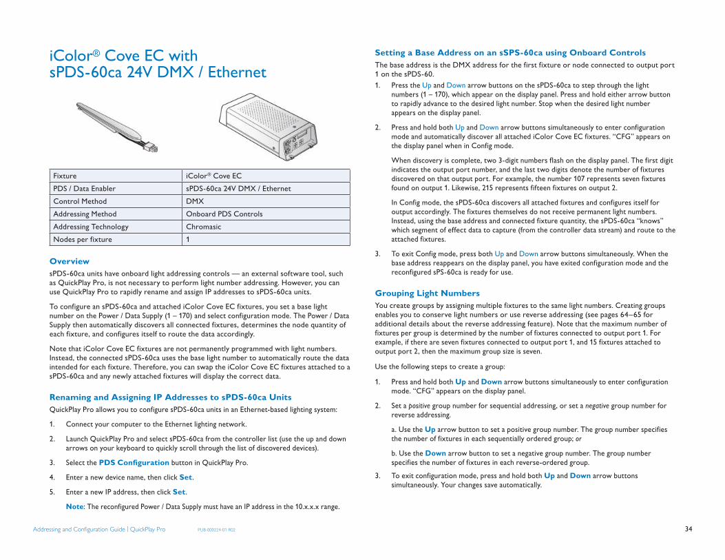
34Addressing and Confi guration Guide | QuickPlay Pro PUB-000224-01 R02
iColor® Cove EC with sPDS-60ca 24V DMX / Ethernet
Fixture iColor® Cove ECPDS / Data Enabler sPDS-60ca 24V DMX / Ethernet Control Method DMXAddressing Method Onboard PDS ControlsAddressing Technology ChromasicNodes per fixture 1
OverviewsPDS-60ca units have onboard light addressing controls — an external software tool, such as QuickPlay Pro, is not necessary to perform light number addressing. However, you can use QuickPlay Pro to rapidly rename and assign IP addresses to sPDS-60ca units.
To configure an sPDS-60ca and attached iColor Cove EC fixtures, you set a base light number on the Power / Data Supply (1 – 170) and select configuration mode. The Power / Data Supply then automatically discovers all connected fixtures, determines the node quantity of each fixture, and configures itself to route the data accordingly.
Note that iColor Cove EC fixtures are not permanently programmed with light numbers. Instead, the connected sPDS-60ca uses the base light number to automatically route the data intended for each fixture. Therefore, you can swap the iColor Cove EC fixtures attached to a sPDS-60ca and any newly attached fixtures will display the correct data.
Renaming and Assigning IP Addresses to sPDS-60ca UnitsQuickPlay Pro allows you to configure sPDS-60ca units in an Ethernet-based lighting system:
1. Connect your computer to the Ethernet lighting network.
2. Launch QuickPlay Pro and select sPDS-60ca from the controller list (use the up and down arrows on your keyboard to quickly scroll through the list of discovered devices).
3. Select the PDS Confi guration button in QuickPlay Pro.
4. Enter a new device name, then click Set.
5. Enter a new IP address, then click Set.
Note: The reconfigured Power / Data Supply must have an IP address in the 10.x.x.x range.
Setting a Base Address on an sSPS-60ca using Onboard ControlsThe base address is the DMX address for the first fixture or node connected to output port 1 on the sPDS-60.1. Press the Up and Down arrow buttons on the sPDS-60ca to step through the light
numbers (1 – 170), which appear on the display panel. Press and hold either arrow button to rapidly advance to the desired light number. Stop when the desired light number appears on the display panel.
2. Press and hold both Up and Down arrow buttons simultaneously to enter configuration mode and automatically discover all attached iColor Cove EC fixtures. “CFG” appears on the display panel when in Config mode.
When discovery is complete, two 3-digit numbers flash on the display panel. The first digit indicates the output port number, and the last two digits denote the number of fixtures discovered on that output port. For example, the number 107 represents seven fixtures found on output 1. Likewise, 215 represents fifteen fixtures on output 2.
In Config mode, the sPDS-60ca discovers all attached fixtures and configures itself for output accordingly. The fixtures themselves do not receive permanent light numbers. Instead, using the base address and connected fixture quantity, the sPDS-60ca “knows” which segment of effect data to capture (from the controller data stream) and route to the attached fixtures.
3. To exit Config mode, press both Up and Down arrow buttons simultaneously. When the base address reappears on the display panel, you have exited configuration mode and the reconfigured sPS-60ca is ready for use.
Grouping Light NumbersYou create groups by assigning multiple fixtures to the same light numbers. Creating groups enables you to conserve light numbers or use reverse addressing (see pages 64–65 for additional details about the reverse addressing feature). Note that the maximum number of fixtures per group is determined by the number of fixtures connected to output port 1. For example, if there are seven fixtures connected to output port 1, and 15 fixtures attached to output port 2, then the maximum group size is seven.
Use the following steps to create a group:
1. Press and hold both Up and Down arrow buttons simultaneously to enter configuration mode. “CFG” appears on the display panel.
2. Set a positive group number for sequential addressing, or set a negative group number for reverse addressing.
a. Use the Up arrow button to set a positive group number. The group number specifies the number of fixtures in each sequentially ordered group; or
b. Use the Down arrow button to set a negative group number. The group number specifies the number of fixtures in each reverse-ordered group.
3. To exit configuration mode, press and hold both Up and Down arrow buttons simultaneously. Your changes save automatically.
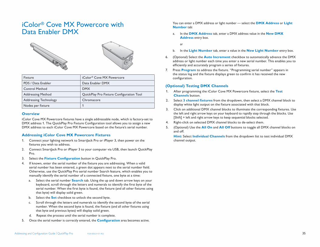
35Addressing and Confi guration Guide | QuickPlay Pro PUB-000224-01 R02
iColor® Cove MX Powercore with Data Enabler DMX
Fixture iColor® Cove MX PowercorePDS / Data Enabler Data Enabler DMX Control Method DMXAddressing Method QuickPlay Pro Fixture Configuration ToolAddressing Technology ChromacoreNodes per fixture 1
OverviewiColor Cove MX Powercore fixtures have a single addressable node, which is factory-set to DMX address 1. The QuickPlay Pro Fixture Configuration tool allows you to assign a new DMX address to each iColor Cove MX Powercore based on the fixture’s serial number.
Addressing iColor Cove MX Powercore Fixtures 1. Connect your lighting network to SmartJack Pro or iPlayer 3, then power on the
fixtures you wish to address.2. Connect SmartJack Pro or iPlayer 3 to your computer via USB, then launch QuickPlay
Pro.3. Select the Fixture Confi guration button in QuickPlay Pro.4. If known, enter the serial number of the fixture you are addressing. When a valid
serial number has been entered, a green dot appears next to the serial number field. Otherwise, use the QuickPlay Pro serial number Search feature, which enables you to manually identify the serial number of a connected fixture, one byte at a time:a. Select the serial number Search tab. Using the up and down arrow keys on your
keyboard, scroll through the letters and numerals to identify the first byte of the serial number. When the first byte is found, the fixture (and all other fixtures using that byte) will display solid green.
b. Select the Set checkbox to unlock the second byte.c. Scroll through the letters and numerals to identify the second byte of the serial
number. When the second byte is found, the fixture (and all other fixtures using that byte and previous bytes) will display solid green.
d. Repeat the process until the serial number is complete.5. Once the serial number is correctly entered, the Confi guration area becomes active.
You can enter a DMX address or light number — select the DMX Address or Light Number tab:
a. In the DMX Address tab, enter a DMX address value in the New DMX Address entry box.
or
b. In the Light Number tab, enter a value in the New Light Number entry box.
6. (Optional) Select the Auto Increment checkbox to automatically advance the DMX address or light number each time you enter a new serial number. This enables you to efficiently and accurately program a series of fixtures.
7. Press Program to address the fixture. “Programming serial number” appears in the status log and the fixture displays green to confirm it has received the new configuration.
(Optional) Testing DMX Channels1. After programming the iColor Cove MX Powercore fixture, select the Test
Channels button.2. Select 3 channel fixtures from the dropdown, then select a DMX channel block to
display white light output on the fixture associated with that block.3. Click on additional DMX channel blocks to illuminate the corresponding fixtures. Use
the left and right arrow keys on your keyboard to rapidly step through the blocks. Use [Shift] + left and right arrow keys to keep sequential blocks selected.
4. Right-click on selected DMX channel blocks to de-select them.5. (Optional) Use the All On and All Off buttons to toggle all DMX channel blocks on
and off. Hint: Select Individual Channels from the dropdown list to test individual DMX
channel output.

36Addressing and Confi guration Guide | QuickPlay Pro PUB-000224-01 R02
iColor® Cove MX Powercore with Data Enabler Ethernet
Fixture iColor® Cove MX PowercorePDS / Data Enabler Data Enabler Ethernet Control Method EthernetAddressing Method QuickPlay Pro Fixture Configuration ToolAddressing Technology ChromacoreNodes per fixture 1
OverviewiColor Cove MX Powercore fixtures have a single addressable node, which is factory-set to DMX address 1. The QuickPlay Pro Fixture Configuration tool allows you to assign a new DMX address to each iColor Cove MX Powercore based on the fixture’s serial number. QuickPlay Pro connects directly to the lighting network via Ethernet.
Addressing iColor Cove MX Powercore Fixtures 1. Connect to your lighting network via Ethernet and power on the fixtures you wish to
address.2. Launch QuickPlay Pro.3. Using the up and down arrow keys on your keyboard, select the appropriate
Data Enabler from the controller list. As you step through the Data Enablers, the corresponding fixtures display solid green, the currently playing effect, or, if in test mode, the selected light numbers or DMX addresses.
4. Select Fixture Confi guration.5. Click Discover to automatically locate all fixture serial numbers.6. Using the up and down arrow keys on your keyboard, select the serial number of the
fixture you wish to address. As you step through the serial numbers, the fixture whose serial number is selected turns green, all others are off.
7. Select the DMX Address tab.8. (Optional) Click Read to discover the current DMX address.9. Enter a DMX address value in the New DMX Address entry box. 10. (Optional) Select the Auto Increment checkbox to automatically increment the
DMX address as fixture serial numbers are selected.
11. Press Program to address the fixture. “Programming serial number” appears in the status log and the fixture displays green to confirm it has received the new configuration.
(Optional) Testing DMX Channels1. After programming the iColor Cove MX Powercore fixture, select the Test
Channels button.2. Select 3 channel fixtures from the dropdown, then select a DMX channel block to
display white light output on the fixture associated with that block.3. Click on additional DMX channel blocks to illuminate the corresponding fixtures. Use
the left and right arrow keys on your keyboard to rapidly step through the blocks. Use [Shift] + left and right arrow keys to keep sequential blocks selected.
4. Right-click on selected DMX channel blocks to de-select them.5. (Optional) Use the All On and All Off buttons to toggle all DMX channel blocks on
and off. Hint: Select Individual Channels from the dropdown list to test individual DMX
channel output.
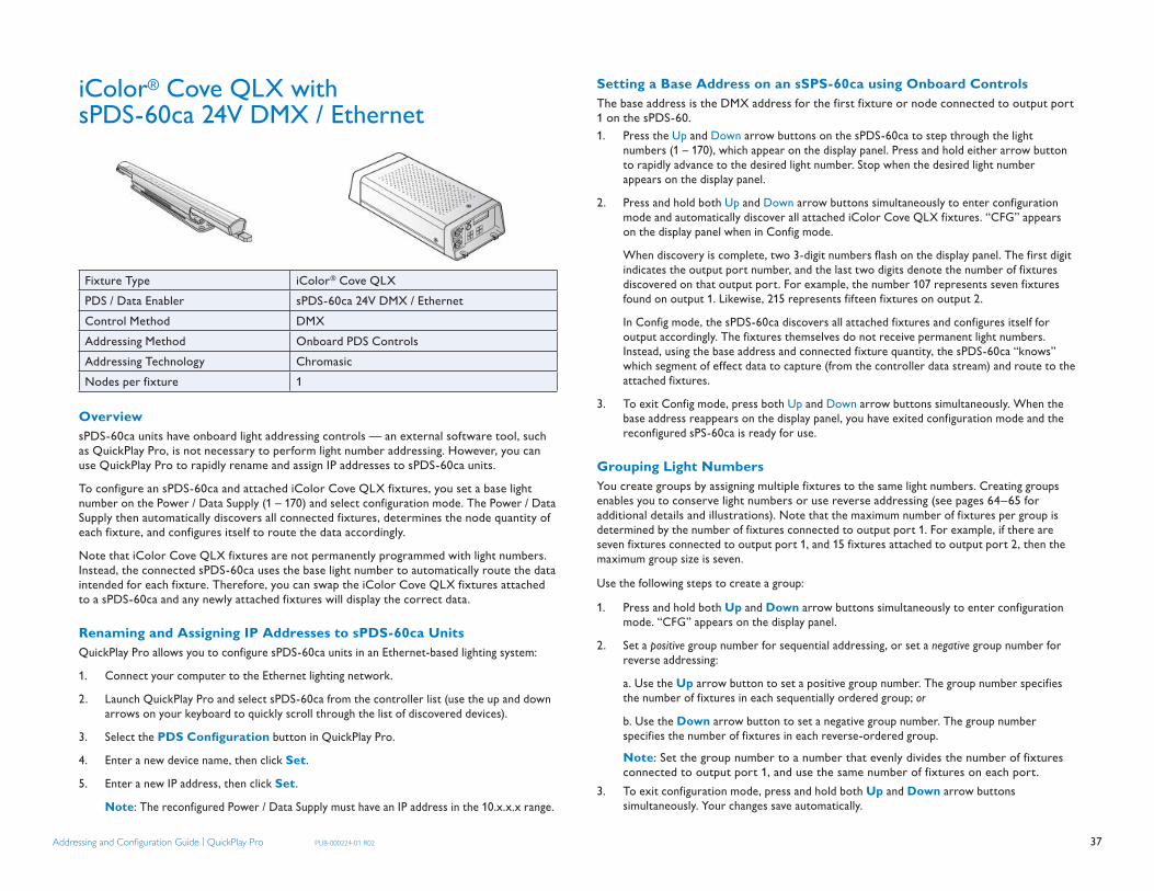
37Addressing and Confi guration Guide | QuickPlay Pro PUB-000224-01 R02
iColor® Cove QLX with sPDS-60ca 24V DMX / Ethernet
Fixture Type iColor® Cove QLXPDS / Data Enabler sPDS-60ca 24V DMX / Ethernet Control Method DMXAddressing Method Onboard PDS ControlsAddressing Technology ChromasicNodes per fixture 1
OverviewsPDS-60ca units have onboard light addressing controls — an external software tool, such as QuickPlay Pro, is not necessary to perform light number addressing. However, you can use QuickPlay Pro to rapidly rename and assign IP addresses to sPDS-60ca units.
To configure an sPDS-60ca and attached iColor Cove QLX fixtures, you set a base light number on the Power / Data Supply (1 – 170) and select configuration mode. The Power / Data Supply then automatically discovers all connected fixtures, determines the node quantity of each fixture, and configures itself to route the data accordingly.
Note that iColor Cove QLX fixtures are not permanently programmed with light numbers. Instead, the connected sPDS-60ca uses the base light number to automatically route the data intended for each fixture. Therefore, you can swap the iColor Cove QLX fixtures attached to a sPDS-60ca and any newly attached fixtures will display the correct data.
Renaming and Assigning IP Addresses to sPDS-60ca UnitsQuickPlay Pro allows you to configure sPDS-60ca units in an Ethernet-based lighting system:
1. Connect your computer to the Ethernet lighting network.
2. Launch QuickPlay Pro and select sPDS-60ca from the controller list (use the up and down arrows on your keyboard to quickly scroll through the list of discovered devices).
3. Select the PDS Confi guration button in QuickPlay Pro.
4. Enter a new device name, then click Set.
5. Enter a new IP address, then click Set.
Note: The reconfigured Power / Data Supply must have an IP address in the 10.x.x.x range.
Setting a Base Address on an sSPS-60ca using Onboard ControlsThe base address is the DMX address for the first fixture or node connected to output port 1 on the sPDS-60.1. Press the Up and Down arrow buttons on the sPDS-60ca to step through the light
numbers (1 – 170), which appear on the display panel. Press and hold either arrow button to rapidly advance to the desired light number. Stop when the desired light number appears on the display panel.
2. Press and hold both Up and Down arrow buttons simultaneously to enter configuration mode and automatically discover all attached iColor Cove QLX fixtures. “CFG” appears on the display panel when in Config mode.
When discovery is complete, two 3-digit numbers flash on the display panel. The first digit indicates the output port number, and the last two digits denote the number of fixtures discovered on that output port. For example, the number 107 represents seven fixtures found on output 1. Likewise, 215 represents fifteen fixtures on output 2.
In Config mode, the sPDS-60ca discovers all attached fixtures and configures itself for output accordingly. The fixtures themselves do not receive permanent light numbers. Instead, using the base address and connected fixture quantity, the sPDS-60ca “knows” which segment of effect data to capture (from the controller data stream) and route to the attached fixtures.
3. To exit Config mode, press both Up and Down arrow buttons simultaneously. When the base address reappears on the display panel, you have exited configuration mode and the reconfigured sPS-60ca is ready for use.
Grouping Light NumbersYou create groups by assigning multiple fixtures to the same light numbers. Creating groups enables you to conserve light numbers or use reverse addressing (see pages 64–65 for additional details and illustrations). Note that the maximum number of fixtures per group is determined by the number of fixtures connected to output port 1. For example, if there are seven fixtures connected to output port 1, and 15 fixtures attached to output port 2, then the maximum group size is seven.
Use the following steps to create a group:
1. Press and hold both Up and Down arrow buttons simultaneously to enter configuration mode. “CFG” appears on the display panel.
2. Set a positive group number for sequential addressing, or set a negative group number for reverse addressing:
a. Use the Up arrow button to set a positive group number. The group number specifies the number of fixtures in each sequentially ordered group; or
b. Use the Down arrow button to set a negative group number. The group number specifies the number of fixtures in each reverse-ordered group.
Note: Set the group number to a number that evenly divides the number of fixtures connected to output port 1, and use the same number of fixtures on each port.
3. To exit configuration mode, press and hold both Up and Down arrow buttons simultaneously. Your changes save automatically.

38Addressing and Confi guration Guide | QuickPlay Pro PUB-000224-01 R02
iColor® Cove QLX with PDS-60ca 24V DMX / Ethernet
Fixture Type iColor® Cove QLXPDS / Data Enabler PDS-60ca 24V DMX / EthernetControl Method DMXAddressing Method QuickPlay Pro PDS Configuration ToolAddressing Technology ChromasicNodes per fixture 1
OverviewTo program a PDS-60ca, you use QuickPlay Pro to set a base light number (1 – 170) and specify the node quantity of each attached fixture. The Power / Data Supply then configures itself to route the correct data to the attached fixtures, beginning with the first node on output port 1 and ending with the last node on output port 2. Note that iColor Cove QLX fixtures are not programmed with light numbers. Instead the connected Power / Data Supply receives a base light number, which it uses to capture and automatically route the correct data to each node in the fixtures. Therefore, you can swap the iColor Cove QLX fixtures attached to a PDS-60ca and the newly attached fixtures will always display the correct data.
Addressing a PDS-60ca Connected to iColor Cove QLX Fixtures1. Connect the PDS-60ca directly to SmartJack Pro or iPlayer 3. Disconnect all other
Power / Data Supplies in the network.2. Connect SmartJack Pro or iPlayer 3 to your computer via USB, then launch QuickPlay
Pro. 3. (Optional, for iPlayer 3) Select a specific output port, or select All to send the same
light data to all output ports.4. Select the PDS Confi guration button.5. Select the correct tab for your Power / Data Supply, PDS-60ca DMX or PDS-60ca
DMX / Ethernet.6. By default, QuickPlay Pro enters the maximum node count for each port (72) in the
Node Count for Output 1 or Node Count for Output 2 fields. Determine the node counts of your fixtures and enter the values in the Node Count for Output 1 and Node Count for Output 2 fields.
7. Enter the desired DMX address in the Base Light Number field.
8. There are two options for configuring how the Power / Data Supply routes data to the fixtures, sequential addressing and all same address:
Sequential Addressing a. Leave the All Same Address box unchecked. b. Click Program. The base address is the light number associated with the first
node on OUT 1. The remaining nodes are associated with light numbers in sequential order through the last node on OUT 2. Fixtures display green when programming is complete.
Set All Fixtures to the Same Light Number a. Check the All Same Address box. b. Click Program. The base address determines the light number associated with
all of the nodes on OUT 1 and OUT 2. Fixtures display green when programming is complete.
(Optional) Testing DMX Channels1. After programming the iColor Cove QLX fixture, select the Test Channels button.2. Select 3 channel fixtures from the dropdown, then select a DMX channel block to
display white light output on the fixture associated with that block.3. Click on additional DMX channel blocks to illuminate the corresponding fixtures. Use
the left and right arrow keys on your keyboard to rapidly step through the blocks. Use [Shift] + left and right arrow keys to keep sequential blocks selected.
4. Right-click on selected DMX channel blocks to de-select them.5. (Optional) Use the All On and All Off buttons to toggle all DMX channel blocks on
and off. Hint: Select Individual Channels from the dropdown list to test individual DMX
channel output.

39Addressing and Confi guration Guide | QuickPlay Pro PUB-000224-01 R02
iColor® Cove QLX with sPDS-480ca 24V Ethernet
Fixture Type iColor® Cove QLXPDS / Data Enabler sPDS-480ca 24V EthernetControl Method EthernetAddressing Method Onboard PDS controlsAddressing Technology ChromasicNodes per fixture 1
OverviewWorking in conjunction with light maps created for Light System Manager (LSM) or Video System Manager Pro (VSM Pro), sPDS-480ca units route light output data to iColor Cove QLX fixtures.
To be included in a light map, each sPDS-480ca must have a unique IP address. You can use either the onboard controls or QuickPlay Pro to configure sPDS-480ca units with IP addresses.
Note that iColor Cove QLX fixtures attached to an sPDS-480ca are not permanently programmed with light numbers. Instead, each sPDS-480ca automatically routes data intended for specific fixtures, based on the light map. Therefore, you can swap the iColor Cove QLX fixtures attached to an sPDS-480ca and any newly attached fixtures will display the correct data.
Renaming and Assigning IP Addresses to sPDS-480ca Units using QuickPlay ProQuickPlay Pro allows you to configure sPDS-480ca units in an Ethernet-based lighting system:
1. Connect your computer to the Ethernet lighting network.
2. Launch QuickPlay Pro and select an sPDS-480ca from the Controller list:
Use the up and down arrows on your keyboard to scroll through the list of controllers and Power / Data Supplies, selecting the sPDS-480ca you intend to configure.
3. Select the PDS Confi guration button in QuickPlay Pro.
4. Enter a new device name, then click Set.
5. Enter a new IP address, then click Set.
Note: Select an IP address in the form of 10.x.x.x. Do not use 10.1.3.100 or 10.1.3.101, as these IP addresses are reserved for the LSM and VSM Pro, respectively.
Assigning IP Addresses to sPDS-480ca Units using Onboard Controls
Cancel Up Down Select
Each sPDS-480ca has four front panel buttons (Cancel, Up, Down, and Select) and an LCD screen. You can use the front panel buttons to rapidly set the device’s IP address:
1. Connect the sPDS-480ca to the Ethernet lighting network.
2. Press Select to open the menu system. Use the Up and Down buttons to scroll through submenus and menu options. Press Cancel to exit a submenu or close the menu system. (See page 62 for a complete list of menus, submenus, and menu items.)
3. Select Configure Menu > Set IP Address.
4. Use the Up and Down buttons to scroll through and select the first segment of the device IP address. Press Select to advance to the next segment.
Note: Select an IP address in the form of 10.x.x.x. Do not use 10.1.3.100 or 10.1.3.101, as these IP addresses are reserved for the LSM and VSM Pro, respectively.
5. Press Select after setting all IP address segments. At the prompt, press Select again to confirm your entry.
6. (Optional) Affix a weatherproof label to the sPDS-480ca indicating the device IP address, and record the IP address in your lighting design plan.
About Light MapsOnce sPDS-480ca IP address setup is complete, use LSM or VSM Pro to create a map of your installation. The map associates each fixture in the installation with a Power / Data Supply, and functions as a visual representation of your lighting layout.
LSM automatically discovers all connected Power / Data Supplies and fixtures, adding them to your map. Use the LSM software tools to fine-tune or manually add Power / Data Supplies and fixtures to your map. For complete details, refer to the Light System Manager User Guide available at: www.colorkinetics.com/ls/controllers/lsm/.
If using VSM Pro, the map associates each node in each fixture with a pixel of video. Use the VSE Pro interface to customize how pixels are sampled from the source video and displayed on your lighting installation. For complete details, refer to the Video System Manager Pro User Guide available online at: www.colorkinetics.com/ls/controllers/vsmpro/.

40Addressing and Confi guration Guide | QuickPlay Pro PUB-000224-01 R02
iColor® Flex SL with PDS-60ca 7.5V DMX / Ethernet
Fixture iColor® Flex SLPDS / Data Enabler PDS-60ca 7.5V DMX / EthernetControl Method DMXAddressing Method QuickPlay Pro PDS Configuration ToolAddressing Technology ChromasicNodes per fixture 50
OverviewTo program a PDS-60ca, you use QuickPlay Pro to set a base light number (1 – 170) and specify the node quantity of each attached fixture. The Power / Data Supply then configures itself to route the correct data to the attached fixtures, beginning with the first node on output port 1 and ending with the last node on output port 2. Note that iColor Flex SL fixtures are not programmed with light numbers. Instead the connected Power / Data Supply receives a base light number, which it uses to capture and automatically route the correct data to each node in the fixtures. Therefore, you can swap the iColor Flex SL fixtures attached to a PDS-60ca and the newly attached fixtures will always display the correct data.
Addressing a PDS-60ca Connected to iColor Flex SL Fixtures1. Connect the PDS-60ca directly to SmartJack Pro or iPlayer 3. Disconnect all other
Power / Data Supplies in the network.2. Connect SmartJack Pro or iPlayer 3 to your computer via USB, then launch QuickPlay
Pro. 3. (Optional, for iPlayer 3) Select a specific output port, or select All to send the same
light data to all output ports.4. Select the PDS Confi guration button.5. Select the correct tab for your Power / Data Supply, PDS-60ca DMX or PDS-60ca
DMX / Ethernet.6. By default, QuickPlay Pro enters the maximum node count for each port (72) in the
Node Count for Output 1 or Node Count for Output 2 fields. Determine the node counts of your fixtures and enter the values in the Node Count for Output 1 and Node Count for Output 2 fields.
7. Enter the desired DMX address in the Base Light Number field.
8. There are two options for configuring how the Power / Data Supply routes data to the fixtures, sequential addressing and all same address:
Sequential Addressing a. Leave the All Same Address box unchecked. b. Click Program. The base address is the light number associated with the first
node on OUT 1. The remaining nodes are associated with light numbers in sequential order through the last node on OUT 2. Fixtures display green when programming is complete.
Set All Fixtures to the Same Light Number a. Check the All Same Address box. b. Click Program. The base address determines the light number associated with
all of the nodes on OUT 1 and OUT 2. Fixtures display green when programming is complete.
(Optional) Testing DMX Channels1. After programming the iColor Flex SL fixture, select the Test Channels button.2. Select 3 channel fixtures from the dropdown, then select a DMX channel block to
display white light output on the fixture associated with that block.3. Click on additional DMX channel blocks to illuminate the corresponding fixtures. Use
the left and right arrow keys on your keyboard to rapidly step through the blocks. Use [Shift] + left and right arrow keys to keep sequential blocks selected.
4. Right-click on selected DMX channel blocks to de-select them.5. (Optional) Use the All On and All Off buttons to toggle all DMX channel blocks on
and off. Hint: Select Individual Channels from the dropdown list to test individual DMX
channel output..

41Addressing and Confi guration Guide | QuickPlay Pro PUB-000224-01 R02
iColor® Flex SL with sPDS-480ca 7.5V Ethernet
Fixture Type iColor® Flex SLPDS / Data Enabler sPDS-480ca 7.5V EthernetControl Method EthernetAddressing Method Onboard PDS controlsAddressing Technology ChromasicNodes per fixture 50
OverviewWorking in conjunction with light maps created for Light System Manager (LSM) or Video System Manager Pro (VSM Pro), sPDS-480ca units route light output data to iColor Flex SL fixtures.
To be included in a light map, each sPDS-480ca must have a unique IP address. You can use either the onboard controls or QuickPlay Pro to configure sPDS-480ca units with IP addresses.
Note that iColor Cove Flex SL fixtures attached to an sPDS-480ca are not permanently programmed with light numbers. Instead, each sPDS-480ca automatically routes data intended for specific fixtures, based on the light map. Therefore, you can swap the iColor Flex SL fixtures attached to an sPDS-480ca and any newly attached fixtures will display the correct data.
Renaming and Assigning IP Addresses to sPDS-480ca Units using QuickPlay ProQuickPlay Pro allows you to configure sPDS-480ca units in an Ethernet-based lighting system:
1. Connect your computer to the Ethernet lighting network.
2. Launch QuickPlay Pro and select an sPDS-480ca from the Controller list:
Use the up and down arrows on your keyboard to scroll through the list of controllers and Power / Data Supplies, selecting the sPDS-480ca you intend to configure.
3. Select the PDS Confi guration button in QuickPlay Pro.
4. Enter a new device name, then click Set.
5. Enter a new IP address, then click Set.
Note: Select an IP address in the form of 10.x.x.x. Do not use 10.1.3.100 or 10.1.3.101, as these IP addresses are reserved for the LSM and VSM Pro, respectively.
Assigning IP Addresses to sPDS-480ca Units using Onboard Controls
Cancel Up Down Select
Each sPDS-480ca has four front panel buttons (Cancel, Up, Down, and Select) and an LCD screen. You can use the front panel buttons to rapidly set the device’s IP address:
1. Connect the sPDS-480ca to the Ethernet lighting network.
2. Press Select to open the menu system. Use the Up and Down buttons to scroll through submenus and menu options. Press Cancel to exit a submenu or close the menu system. (See page 62 for a complete list of menus, submenus, and menu items.)
3. Select Configure Menu > Set IP Address.
4. Use the Up and Down buttons to scroll through and select the first segment of the device IP address. Press Select to advance to the next segment.
Note: Select an IP address in the form of 10.x.x.x. Do not use 10.1.3.100 or 10.1.3.101, as these IP addresses are reserved for the LSM and VSM Pro, respectively.
5. Press Select after setting all IP address segments. At the prompt, press Select again to confirm your entry.
6. (Optional) Affix a weatherproof label to the sPDS-480ca indicating the device IP address, and record the IP address in your lighting design plan.
About Light MapsOnce sPDS-480ca IP address setup is complete, use LSM or VSM Pro to create a map of your installation. The map associates each fixture in the installation with a Power / Data Supply, and functions as a visual representation of your lighting layout.
LSM automatically discovers all connected Power / Data Supplies and fixtures, adding them to your map. Use the LSM software tools to fine-tune or manually add Power / Data Supplies and fixtures to your map. For complete details, refer to the Light System Manager User Guide available at: www.colorkinetics.com/ls/controllers/lsm/.
If using VSM Pro, the map associates each node in each fixture with a pixel of video. Use the VSE Pro interface to customize how pixels are sampled from the source video and displayed on your lighting installation. For complete details, refer to the Video System Manager Pro User Guide available online at: www.colorkinetics.com/ls/controllers/vsmpro/.

42Addressing and Confi guration Guide | QuickPlay Pro PUB-000224-01 R02
iColor® Flex SLX with PDS-60ca 12V DMX / Ethernet
Fixture iColor® Flex SLXPDS / Data Enabler PDS-60ca 12V DMX / EthernetControl Method DMXAddressing Method QuickPlay Pro PDS Configuration ToolAddressing Technology ChromasicNodes per fixture 50
OverviewTo program a PDS-60ca, you use QuickPlay Pro to set a base light number (1 – 170) and specify the node quantity of each attached fixture. The Power / Data Supply then configures itself to route the correct data to the attached fixtures, beginning with the first node on output port 1 and ending with the last node on output port 2. Note that iColor Flex SLX fixtures are not programmed with light numbers. Instead the connected Power / Data Supply receives a base light number, which it uses to capture and automatically route the correct data to each node in the fixtures. Therefore, you can swap the iColor Flex SL fixtures attached to a PDS-60ca and the newly attached fixtures will always display the correct data.
Addressing a PDS-60ca Connected to iColor Flex SLX Fixtures1. Connect the PDS-60ca directly to SmartJack Pro or iPlayer 3. Disconnect all other
Power / Data Supplies in the network.2. Connect SmartJack Pro or iPlayer 3 to your computer via USB, then launch QuickPlay
Pro. 3. (Optional, for iPlayer 3) Select a specific output port, or select All to send the same
light data to all output ports.4. Select the PDS Confi guration button.5. Select the correct tab for your Power / Data Supply, PDS-60ca DMX or PDS-60ca
DMX / Ethernet.6. By default, QuickPlay Pro enters the maximum node count for each port (72) in the
Node Count for Output 1 or Node Count for Output 2 fields. Determine the node counts of your fixtures and the values in the Node Count for Output 1 or Node Count for Output 2 fields.
7. Enter the desired DMX address in the Base Light Number field.8. There are two options for configuring how the Power / Data Supply routes data to the
fixtures, sequential addressing and all same address: Sequential Addressing a. Leave the All Same Address box unchecked. b. Click Program. The base address is the light number associated with the first
node on OUT 1. The remaining nodes are associated with light numbers in sequential order through the last node on OUT 2. Fixtures display green when programming is complete.
Set All Fixtures to the Same Light Number a. Check the All Same Address box. b. Click Program. The base address determines the light number associated with
all of the nodes on OUT 1 and OUT 2. Fixtures display green when programming is complete.
(Optional) Testing DMX Channels1. After programming the iColor Flex SLX fixture, select the Test Channels button.2. Select 3 channel fixtures from the dropdown, then select a DMX channel block to
display white light output on the fixture associated with that block.3. Click on additional DMX channel blocks to illuminate the corresponding fixtures. Use
the left and right arrow keys on your keyboard to rapidly step through the blocks. Use [Shift] + left and right arrow keys to keep sequential blocks selected.
4. Right-click on selected DMX channel blocks to de-select them.5. (Optional) Use the All On and All Off buttons to toggle all DMX channel blocks on
and off. Hint: Select Individual Channels from the dropdown list to test individual DMX
channel output.

43Addressing and Confi guration Guide | QuickPlay Pro PUB-000224-01 R02
iColor® Flex SLX with sPDS-480ca 12V Ethernet
Fixture Type iColor® Flex SLXPDS / Data Enabler sPDS-480ca 12V EthernetControl Method EthernetAddressing Method Onboard PDS controlsAddressing Technology ChromasicNodes per fixture 50
OverviewWorking in conjunction with light maps created for Light System Manager (LSM) or Video System Manager Pro (VSM Pro), sPDS-480ca units route light output data to iColor Flex SLX fixtures.
To be included in a light map, each sPDS-480ca must have a unique IP address. You can use either the onboard controls or QuickPlay Pro to configure sPDS-480ca units with IP addresses.
Note that iColor Cove Flex SLX fixtures attached to an sPDS-480ca are not permanently programmed with light numbers. Instead, each sPDS-480ca automatically routes data intended for specific fixtures, based on the light map. Therefore, you can swap the iColor Flex SLX fixtures attached to an sPDS-480ca and any newly attached fixtures will display the correct data.
Renaming and Assigning IP Addresses to sPDS-480ca Units using QuickPlay ProQuickPlay Pro allows you to configure sPDS-480ca units in an Ethernet-based lighting system:
1. Connect your computer to the Ethernet lighting network.
2. Launch QuickPlay Pro and select an sPDS-480ca from the Controller list:
Use the up and down arrows on your keyboard to scroll through the list of controllers and power / data supplies, selecting the sPDS-480ca you intend to configure.
3. Select the PDS Confi guration button in QuickPlay Pro.
4. Enter a new device name, then click Set.
5. Enter a new IP address, then click Set.
Note: Select an IP address in the form of 10.x.x.x. Do not use 10.1.3.100 or 10.1.3.101, as these IP addresses are reserved for the LSM and VSM Pro, respectively.
Assigning IP Addresses to sPDS-480ca Units using Onboard Controls
Cancel Up Down Select
Each sPDS-480ca has four front panel buttons (Cancel, Up, Down, and Select) and an LCD screen. You can use the front panel buttons to rapidly set the device’s IP address:
1. Connect the sPDS-480ca to the Ethernet lighting network.
2. Press Select to open the menu system. Use the Up and Down buttons to scroll through submenus and menu options. Press Cancel to exit a submenu or close the menu system. (See page 62 for a complete list of menus, submenus, and menu items.)
3. Select Configure Menu > Set IP Address.
4. Use the Up and Down buttons to scroll through and select the first segment of the device IP address. Press Select to advance to the next segment.
Note: Select an IP address in the form of 10.x.x.x. Do not use 10.1.3.100 or 10.1.3.101, as these IP addresses are reserved for the LSM and VSM Pro, respectively.
5. Press Select after setting all IP address segments. At the prompt, press Select again to confirm your entry.
6. (Optional) Affix a weatherproof label to the sPDS-480ca indicating the device IP address, and record the IP address in your lighting design plan.
About Light MapsOnce sPDS-480ca IP address setup is complete, use LSM or VSM Pro to create a map of your installation. The map associates each fixture in the installation with a Power / Data Supply, and functions as a visual representation of your lighting layout.
LSM automatically discovers all connected Power / Data Supplies and fixtures, adding them to your map. Use the LSM software tools to fine-tune or manually add Power / Data Supplies and fixtures to your map. For complete details, refer to the Light System Manager User Guide available at: www.colorkinetics.com/ls/controllers/lsm/.
If using VSM Pro, the map associates each node in each fixture with a pixel of video. Use the VSE Pro interface to customize how pixels are sampled from the source video and displayed on your lighting installation. For complete details, refer to the Video System Manager Pro User Guide available online at: www.colorkinetics.com/ls/controllers/vsmpro/.

44Addressing and Confi guration Guide | QuickPlay Pro PUB-000224-01 R02
iColor® Module FX with PDS-60ca 7.5V DMX / Ethernet
Fixture iColor® Module FXPDS / Data Enabler PDS-60ca 7.5V DMX / EthernetControl Method DMXAddressing Method QuickPlay Pro PDS Configuration ToolAddressing Technology ChromasicNodes per fixture 9 or 36
OverviewTo program a PDS-60ca, you use QuickPlay Pro to set a base light number (1 – 170) and specify the node quantity of each attached fixture. The Power / Data Supply then configures itself to route the correct data to the attached fixtures, beginning with the first node on output port 1 and ending with the last node on output port 2. Note that iColor Module FX fixtures are not programmed with light numbers. Instead the Power / Data Supply receives a base light number, which it uses to capture and automatically route the correct data to each node in the attached fixtures. Therefore, you can swap the iColor Module FX fixtures attached to a PDS-60ca and the newly attached fixtures will always display the correct data.
Addressing a PDS-60ca Connected to iColor® Module FX Fixtures 1. Connect the PDS-60ca directly to SmartJack Pro or iPlayer 3. Disconnect all other
Power / Data Supplies in the network.2. Connect SmartJack Pro or iPlayer 3 to your computer via USB, then launch QuickPlay
Pro. 3. (Optional, for iPlayer 3) Select a specific output port, or select All to send the same
light data to all output ports.4. Select the PDS Confi guration button.5. Select the correct tab for your Power / Data Supply, PDS-60ca DMX or PDS-60ca
DMX / Ethernet.6. By default, QuickPlay Pro enters the maximum node count for each port (72) in the
Node Count for Output 1 or Node Count for Output 2 fields. Determine the node counts of your fixtures and enter the values in the Node Count for Output 1 and Node Count for Output 2 fields.
7. Enter the desired DMX address in the Base Light Number field.8. There are two options for configuring how the Power / Data Supply routes data to the
fixtures, sequential addressing and all same address: Sequential Addressing a. Leave the All Same Address box unchecked. b. Click Program. The base address is the light number associated with the first
node on OUT 1. The remaining nodes are associated with light numbers in sequential order through the last node on OUT 2. Fixtures display green when programming is complete.
Set All Fixtures to the Same Light Number a. Check the All Same Address box. b. Click Program. The base address determines the light number associated with
all of the nodes on OUT 1 and OUT 2. Fixtures display green when programming is complete.
(Optional) Testing DMX Channels1. After programming the iColor Module FX fixture, select the Test Channels button.2. Select 3 channel fixtures from the dropdown, then select a DMX channel block to
display white light output on the fixture associated with that block.3. Click on additional DMX channel blocks to illuminate the corresponding fixtures. Use
the left and right arrow keys on your keyboard to rapidly step through the blocks. Use [Shift] + left and right arrow keys to keep sequential blocks selected.
4. Right-click on selected DMX channel blocks to de-select them.5. (Optional) Use the All On and All Off buttons to toggle all DMX channel blocks on
and off. Hint: Select Individual Channels from the dropdown list to test individual DMX
channel output.

45Addressing and Confi guration Guide | QuickPlay Pro PUB-000224-01 R02
iColor® MR g2 with PDS-70mr 24V DMX
Fixture iColor® MR g2PDS / Data Enabler PDS-70mr 24V DMXControl Method DMXAddressing Method QuickPlay Pro Fixture Configuration ToolAddressing Technology ChromacoreNodes per lamp 1
OverviewiColor MR g2 lamps have a single addressable node, which is factory-set to DMX address 1. The QuickPlay Pro Fixture Configuration tool allows you to assign a new DMX address to each iColor MR g2 based on the lamp’s serial number.
Addressing iColor MR g2 Lamps1. Connect your lighting network to SmartJack Pro or iPlayer 3, then power on the lamps
you wish to address.2. Connect SmartJack Pro or iPlayer 3 to your computer via USB, then launch QuickPlay Pro.3. Select the Fixture Confi guration button in QuickPlay Pro.4. If known, enter the serial number of the fixture you are addressing. When a valid
serial number has been entered, a green dot appears next to the serial number field. Otherwise, use the QuickPlay Pro serial number Search feature, which enables you to manually identify the serial number of the connected lamp, one byte at a time:a. Select the serial number Search tab. Using the up and down arrow keys on your
keyboard, scroll through the letters and numerals to identify the first byte of the serial number. When the first byte is found, the lamp (and all other lamps using that byte) will display solid green.
b. Select the Set checkbox to unlock the second byte.c. Scroll through the letters and numerals to identify the second byte of the serial
number. When the second byte is found, the lamp (and all other lamps using that byte and previous bytes) will display solid green.
d. Repeat the process until the serial number is complete.
5. Once the serial number is correctly entered, the Confi guration area becomes active. You can enter a DMX address or light number — select the DMX Address or Light Number tab:
a. In the DMX Address tab, enter a DMX address value in the New DMX Address entry box.
or
b. In the Light Number tab, enter a value in the New Light Number entry box.
6. (Optional) Select the Auto Increment checkbox to automatically advance the DMX address or light number each time you enter a new serial number. This enables you to efficiently and accurately program a series of fixtures.
7. Press Program to address the fixture. “Programming serial number” appears in the status log and the fixture displays green to confirm it has received the new configuration.
(Optional) Testing DMX Channels1. After programming the iColor MR g2 lamp, select the Test Channels button.2. Select 3 channel fixtures from the dropdown, then select a DMX channel block to
display white light output on the fixture associated with that block.3. Click on additional DMX channel blocks to illuminate the corresponding fixtures. Use
the left and right arrow keys on your keyboard to rapidly step through the blocks. Use [Shift] + left and right arrow keys to keep sequential blocks selected.
4. Right-click on selected DMX channel blocks to de-select them.5. (Optional) Use the All On and All Off buttons to toggle all DMX channel blocks on
and off. Hint: Select Individual Channels from the dropdown list to test individual DMX
channel output.

46Addressing and Confi guration Guide | QuickPlay Pro PUB-000224-01 R02
iColor® MR g2 with PDS-70mr 24V Ethernet
Fixture iColor® MR g2PDS / Data Enabler PDS-70mr 24V EthernetControl Method EthernetAddressing Method QuickPlay Pro Fixture Configuration ToolAddressing Technology ChromacoreNodes per lamp 1
OverviewiColor MR g2 lamps have a single addressable node, which is factory-set to DMX address 1. The QuickPlay Pro Fixture Configuration tool allows you to assign a DMX address to each iColor MR g2 based on the lamp’s serial number. QuickPlay Pro connects directly to the lighting network via Ethernet.
Addressing iColor MR g2 Lamps1. Connect to your lighting network via Ethernet and power on the lamps you wish
to address.2. Using the up and down arrow keys on your keyboard, select the appropriate
Data Enabler from the controller list. As you step through the Data Enablers, the corresponding lamps display solid green, the currently playing effect, or, if in test mode, the selected light numbers or DMX addresses.
3. Select the Fixture Confi guration button in QuickPlay Pro.4. Click Discover to automatically locate all lamp serial numbers.5. Using the up and down arrow keys on your keyboard, select the serial number of the
fixture you wish to address. As you step through the serial numbers, the fixture whose serial number is selected turns green, all others are off.
6. Select the DMX Address tab.7. (Optional) Click Read to discover the current DMX address.8. Enter a DMX address in the New DMX Address entry box. 9. (Optional) Select the Auto Increment checkbox to automatically increment DMX
addresses as lamp serial numbers are selected.10. Click Program to address the lamp.
(Optional) Testing DMX Channels1. After programming the iColor MR g2 lamp, select the Test Channels button.2. Select 3 channel fixtures from the dropdown, then select a DMX channel block to
display white light output on the fixture associated with that block.3. Click on additional DMX channel blocks to illuminate the corresponding fixtures. Use
the left and right arrow keys on your keyboard to rapidly step through the blocks. Use [Shift] + left and right arrow keys to keep sequential blocks selected.
4. Right-click on selected DMX channel blocks to de-select them.5. (Optional) Use the All On and All Off buttons to toggle all DMX channel blocks on
and off. Hint: Select Individual Channels from the dropdown list to test individual DMX
channel output.

47Addressing and Confi guration Guide | QuickPlay Pro PUB-000224-01 R02
iColor® Tile FX 2:2 with PDS-60ca 7.5V DMX / Ethernet
Fixture iColor® Tile 2:2PDS / Data Enabler PDS-60ca 7.5V DMX / EthernetControl Method DMXAddressing Method QuickPlay Pro PDS Configuration ToolAddressing Technology ChromasicNodes per fixture 144
OverviewTo program a PDS-60ca, you use QuickPlay Pro to set a base light number (1 – 170) and specify the node quantity of the attached fixture (144). The Power / Data Supply then configures itself to route the correct data to the attached fixtures, beginning with the first node on output port 1 and ending with the last node on output port 2. Note that iColor Tile FX 2:2 fixtures are not programmed with light numbers. Instead the Power / Data Supply receives a base light number, which it uses to capture and automatically route the correct data to each node in the attached fixture. Therefore, you can swap the iColor Tile FX 2:2 fixture attached to a PDS-60ca and the newly attached fixture will always display the correct data
Addressing a PDS-60ca Connected to iColor Tile FX 2:2 Fixtures1. Connect the PDS-60ca directly to SmartJack Pro or iPlayer 3. Disconnect all other
Power / Data Supplies in the network.2. Connect SmartJack Pro or iPlayer 3 to your computer via USB, then launch QuickPlay
Pro. 3. (Optional, for iPlayer 3) Select a specific output port, or select All to send the same
light data to all output ports.4. Select the PDS Confi guration button.5. Select the correct tab for your Power / Data Supply, PDS-60ca DMX or PDS-60ca
DMX / Ethernet.6. By default, QuickPlay Pro enters the maximum node count for each port (72) in the
Node Count for Output 1 or Node Count for Output 2 fields. Determine the node counts of your fixtures and enter the values in the Node Count for Output 1 and Node Count for Output 2 fields.
7. Enter the desired DMX address in the Base Light Number field.8. There are two options for configuring how the Power / Data Supply routes data to the
fixtures, sequential addressing and all same address: Sequential Addressing a. Leave the All Same Address box unchecked. b. Click Program. The base address is the light number associated with the first
node on OUT 1. The remaining nodes are associated with light numbers in sequential order through the last node on OUT 2. Fixtures display green when programming is complete.
Set All Fixtures to the Same Light Number a. Check the All Same Address box. b. Click Program. The base address determines the light number associated with
all of the nodes on OUT 1 and OUT 2. Fixtures display green when programming is complete.
(Optional) Testing DMX Channels1. After programming the iColor Tile FX 2:2 fixture, select the Test Channels button.2. Select 3 channel fixtures from the dropdown, then select a DMX channel block to
display white light output on the fixture associated with that block.3. Click on additional DMX channel blocks to illuminate the corresponding fixtures. Use
the left and right arrow keys on your keyboard to rapidly step through the blocks. Use [Shift] + left and right arrow keys to keep sequential blocks selected.
4. Right-click on selected DMX channel blocks to de-select them.5. (Optional) Use the All On and All Off buttons to toggle all DMX channel blocks on
and off. Hint: Select Individual Channels from the dropdown list to test individual DMX
channel output.

48Addressing and Confi guration Guide | QuickPlay Pro PUB-000224-01 R02
iW® Blast Powercore withData Enabler DMX
Fixture iW™ Blast PowercorePDS / Data Enabler Data Enabler DMXControl Method DMXAddressing Method QuickPlay Pro Fixture Configuration ToolAddressing Technology ChromacoreNodes per fixture 1
OverviewiW Blast Powercore fixtures are intelligent white light systems designed for use specifically with the iW Data Enabler. However, for non-standard applications requiring integration with color-changing fixtures or fine control of color temperature output, iW Blast Powercore fixtures are compatible with Data Enabler DMX.iW Blast Powercore fixtures have a single addressable node. The QuickPlay Pro Fixture Configuration tool allows you to assign a light number to each iW Blast Powercore based on the fixture’s serial number.QuickPlay Pro connects directly to the DMX network via SmartJack Pro or iPlayer 3.
Addressing iW Blast Powercore Fixtures1. Connect your lighting network to SmartJack Pro or iPlayer 3, then power on the
fixtures you wish to address.2. Connect SmartJack Pro or iPlayer 3 to your computer via USB, then launch QuickPlay Pro.3. Select the Fixture Confi guration button in QuickPlay Pro.4. If known, enter the serial number of the fixture you are addressing. When a valid
serial number has been entered, a green dot appears next to the serial number field. Otherwise, use the QuickPlay Pro serial number Search feature, which enables you to manually identify the serial number of a connected fixture, one byte at a time:a. Select the serial number Search tab. Using the up and down arrow keys on your
keyboard, scroll through the letters and numerals to identify the first byte of the serial number. When the first byte is found, the fixture (and all other fixtures using that byte) will display solid white.
b. Select the Set checkbox to unlock the second byte.c. Scroll through the letters and numerals to identify the second byte of the serial
number. When the second byte is found, the fixture (and all other fixtures using that byte and previous bytes) will display solid white.
d. Repeat the process until the serial number is complete.5. Once the serial number is correctly entered, the Confi guration area becomes active.
You can enter a DMX address or light number — select the DMX Address or Light Number tab:
a. In the DMX Address tab, enter a DMX address value in the New DMX Address entry box.
or
b. In the Light Number tab, enter a value in the New Light Number entry box.
6. (Optional) Select the Auto Increment checkbox to automatically advance the DMX address or light number each time you enter a new serial number. This enables you to efficiently and accurately program a series of fixtures.
7. Press Program to address the fixture. “Programming serial number” appears in the status log and the fixture displays green to confirm it has received the new configuration.
(Optional) Testing DMX Channels1. After programming the iW Blast Powercore fixture, select the Test Channels
button.2. Select 3 channel fixtures from the dropdown, then select a DMX channel block to
display white light output on the fixture associated with that block.3. Click on additional DMX channel blocks to illuminate the corresponding fixtures. Use
the left and right arrow keys on your keyboard to rapidly step through the blocks. Use [Shift] + left and right arrow keys to keep sequential blocks selected.
4. Right-click on selected DMX channel blocks to de-select them.5. (Optional) Use the All On and All Off buttons to toggle all DMX channel blocks on
and off.

49Addressing and Confi guration Guide | QuickPlay Pro PUB-000224-01 R02
iW® Blast Powercore withData Enabler Ethernet
Fixture iW™ Blast PowercorePDS / Data Enabler Data Enabler EthernetControl Method EthernetAddressing Method QuickPlay Pro Fixture Configuration ToolAddressing Technology ChromacoreNodes per fixture 1
OverviewiW Blast Powercore fixtures are intelligent white light systems designed for use specifically with the iW Data Enabler. However, for non-standard applications requiring integration with color-changing fixtures or fine control of color temperature output, iW Blast Powercore fixtures are compatible with Data Enabler Ethernet.iW Blast Powercore fixtures have a single addressable node. The QuickPlay Pro Fixture Configuration tool allows you to assign a light number to each iW Blast Powercore based on the fixture’s serial number. QuickPlay Pro connects directly to the lighting network via Ethernet.
Addressing iW Blast Powercore Fixtures1. Connect to your lighting network via Ethernet and power on the fixtures you wish
to address.2. Using the up and down arrow keys on your keyboard, select the appropriate
Data Enabler from the controller list. As you step through the Data Enablers, the corresponding fixtures display solid white, the currently playing effect, or, if in test mode, the selected light numbers or DMX addresses.
3. Select the Fixture Confi guration button in QuickPlay Pro.4. Click Discover to automatically locate all fixture serial numbers.5. Using the up and down arrow keys on your keyboard, select the serial number of the
fixture you wish to address. As you step through the serial numbers, the fixture whose serial number is selected turns green, all others are off.
6. Select the DMX Address tab.7. (Optional) Click Read to discover the current DMX address.8. Enter a DMX address value in the New DMX Address entry box.
9. (Optional) Select the Auto Increment checkbox to automatically increment the DMX address as fixture serial numbers are selected.
10. Press Program to address the fixture. “Programming serial number” appears in the status log and the fixture displays green to confirm it has received the new configuration.
(Optional) Testing DMX Channels1. After programming the iW Blast Powercore fixture, select the Test Channels
button.2. Select 3 channel fixtures from the dropdown, then select a DMX channel block to
display white light output on the fixture associated with that block.3. Click on additional DMX channel blocks to illuminate the corresponding fixtures. Use
the left and right arrow keys on your keyboard to rapidly step through the blocks. Use [Shift] + left and right arrow keys to keep sequential blocks selected.
4. Right-click on selected DMX channel blocks to de-select them.5. (Optional) Use the All On and All Off buttons to toggle all DMX channel blocks on
and off. Hint: Select Individual Channels from the dropdown list to test individual DMX
channel output.

50Addressing and Confi guration Guide | QuickPlay Pro PUB-000224-01 R02
iW® Blast TR with PDS-750 TR
Fixture iW™ Blast TRPDS / Data Enabler PDS-750 TRControl Method DMXAddressing Method Onboard PDS Address SwitchesAddressing Technology ChromacoreNodes per fixture 1
OverviewPDS-750 TR Power / Data Supplies have onboard addressing controls — an external software tool such as QuickPlay Pro is not necessary to configure fixtures connected to a PDS-750 TR.
Each PDS-750 TR supports up to 12 iW Blast TR fixtures. Using a base DMX address, the PDS-750 TR sequentially routes DMX data to each connected fixture. For example, if “AAA” equals the base DMX address configured on the PDS-750 TR, connected fixtures receive DMX data as follows:
Fixture #1 receives data intended for DMX addresses: AAA, AAA + 1, AAA + 2• Fixture #2 receives data intended for DMX • addresses: AAA + 3, AAA + 4, AAA + 5Fixture #3 receives data intended for DMX • addresses: AAA + 6, AAA + 7, AAA + 8
To function in conjunction with a PDS-750 TR, all connected ColorBlast TR fixtures must be addressed to light number 1.
Addressing iW Blast TR Fixtures to Light Number 11. Power On the PDS-750 TR and select Pass Thru mode by turning all three DMX
switches to 0 (the “Status” light displays orange when the device is in Pass Thru mode).2. Connect up to 12 iW Blast TR fixtures to the PDS-750 TR.3 Press the Mini-Zapi switch on the front of the PDS-750 TR.4. The fixtures will momentarily display red and then flicker.5. When the flickering stops, power Off the PDS-750 TR6. Power back On the PDS-750 TR, to resume operation.
Addressing the PDS-750 TR with a Base DMX Address1. Power On the PDS-750 TR.2. Connect up to 12 iW Blast TR fixtures to ports 1 – 12 (all fixtures must be addressed
to light number 1).3. Connect the PDS-750 TR to a DMX source via the DMX Input.4. Set the base DMX address of the PDS-750 TR using the DMX switches: From left to right, the switches control the 100s, 10s, and 1s DMX values. For
example, to set a DMX base address of 125, turn the first switch to 1, the second switch to 2, and the third switch to 5.
When you have set a base DMX address, the Status light should display green, indicating that the PDS-750 TR is in CB (ColorBlast playback) mode.
5. Test your configuration by sending light output data from the DMX controller.
Standalone Effects ModeStandalone Effects mode allows you to run pre-programmed effects from the PDS-750 TR, for demonstration purposes. Turn the Config switch to any position other than “0” to launch Standalone Effects mode.
Note: The latest PDS-750 TR operator’s manual is available from the City Theatrical, Inc. website (a third-party website), under the Color Kinetics tab: www.citytheatrical.com/.

51Addressing and Confi guration Guide | QuickPlay Pro PUB-000224-01 R02
iW® Cove Powercore withData Enabler DMX
Fixture iW™ Cove PowercorePDS / Data Enabler Data Enabler DMXControl Method DMXAddressing Method QuickPlay Pro Fixture Configuration ToolAddressing Technology ChromacoreNodes per fixture 1
OverviewiW Cove Powercore fixtures are intelligent white light systems designed for use specifically with the iW Data Enabler. However, for non-standard applications requiring integration with color-changing fixtures or fine control of color temperature output, iW Cove Powercore fixtures are compatible with Data Enabler DMX.iW Cove Powercore fixtures have a single addressable node. The QuickPlay Pro Fixture Configuration tool allows you to assign a light number to each iW Cove Powercore based on the fixture’s serial number. QuickPlay Pro connects directly to the DMX lighting network via SmartJack Pro or iPlayer 3.
Addressing iW Cove Powercore Fixtures1. Connect your lighting network to SmartJack Pro or iPlayer 3, then power on the
fixtures you wish to address.2. Connect SmartJack Pro or iPlayer 3 to your computer via USB, then launch QuickPlay Pro.3. Select the Fixture Confi guration button in QuickPlay Pro.4. If known, enter the serial number of the fixture you are addressing. When a valid
serial number has been entered, a green dot appears next to the serial number field. Otherwise, use the QuickPlay Pro serial number Search feature, which enables you to manually identify the serial number of a connected fixture, one byte at a time:a. Select the serial number Search tab. Using the up and down arrow keys on your
keyboard, scroll through the letters and numerals to identify the first byte of the serial number. When the first byte is found, the fixture (and all other fixtures using that byte) will display solid white.
b. Select the Set checkbox to unlock the second byte.
c. Scroll through the letters and numerals to identify the second byte of the serial number. When the second byte is found, the fixture (and all other fixtures using that byte and previous bytes) will display solid white.
d. Repeat the process until the serial number is complete.5. Once the serial number is correctly entered, the Confi guration area becomes active.
You can enter a DMX address or light number — select the DMX Address or Light Number tab:
a. In the DMX Address tab, enter a DMX address value in the New DMX Address entry box.
or
b. In the Light Number tab, enter a value in the New Light Number entry box.
6. (Optional) Select the Auto Increment checkbox to automatically advance the DMX address or light number each time you enter a new serial number. This enables you to efficiently and accurately program a series of fixtures.
7. Press Program to address the fixture. “Programming serial number” appears in the status log and the fixture displays green to confirm it has received the new configuration.
(Optional) Testing DMX Channels1. After programming the iW Cove Powercore fixture, select the Test Channels
button.2. Select 3 channel fixtures from the dropdown, then select a DMX channel block to
display white light output on the fixture associated with that block.3. Click on additional DMX channel blocks to illuminate the corresponding fixtures. Use
the left and right arrow keys on your keyboard to rapidly step through the blocks. Use [Shift] + left and right arrow keys to keep sequential blocks selected.
4. Right-click on selected DMX channel blocks to de-select them.5. (Optional) Use the All On and All Off buttons to toggle all DMX channel blocks on
and off.

52Addressing and Confi guration Guide | QuickPlay Pro PUB-000224-01 R02
iW® Cove Powercore withData Enabler Ethernet
Fixture iW™ Cove PowercorePDS / Data Enabler Data Enabler EthernetControl Method EthernetAddressing Method QuickPlay Pro Fixture Configuration ToolAddressing Technology ChromacoreNodes per fixture 1
OverviewiW Cove Powercore fixtures are intelligent white light systems designed for use specifically with the iW Data Enabler. However, for non-standard applications requiring integration with color-changing fixtures or fine control of color temperature output, iW Cove Powercore fixtures are compatible with Data Enabler Ethernet.iW Cove Powercore fixtures have a single addressable node. The QuickPlay Pro Fixture Configuration tool allows you to assign a light number to each iW Cove Powercore based on the fixture’s serial number. QuickPlay Pro connects directly to the Ethernet lighting network.
Addressing iW Cove Powercore Fixtures1. Connect to your lighting network via Ethernet and power on the fixtures you wish
to address.2. Using the up and down arrow keys on your keyboard, select the appropriate
Data Enabler from the controller list. As you step through the Data Enablers, the corresponding fixtures display solid white, the currently playing effect, or, if in test mode, the selected light numbers or DMX addresses.
3. Select the Fixture Confi guration button in QuickPlay Pro.4. Click Discover to automatically locate all fixture serial numbers.5. Using the up and down arrow keys on your keyboard, select the serial number of the
fixture you wish to address. As you step through the serial numbers, the fixture whose serial number is selected turns green, all others are off.
6. Select the DMX Address tab.7. (Optional) Click Read to discover the current DMX address.8. Enter a DMX address value in the New DMX Address entry box.
9. (Optional) Select the Auto Increment checkbox to automatically increment the DMX address as fixture serial numbers are selected.
10. Press Program to address the fixture. “Programming serial number” appears in the status log and the fixture displays green to confirm it has received the new configuration.
(Optional) Testing Channels1. After programming the iW Cove Powercore fixture, select the Test Channels
button.2. Select 3 channel fixtures from the dropdown, then select a DMX channel block to
display white light output on the fixture associated with that block.3. Click on additional DMX channel blocks to illuminate the corresponding fixtures. Use
the left and right arrow keys on your keyboard to rapidly step through the blocks. Use [Shift] + left and right arrow keys to keep sequential blocks selected.
4. Right-click on selected DMX channel blocks to de-select them.5. (Optional) Use the All On and All Off buttons to toggle all DMX channel blocks on
and off.

53Addressing and Confi guration Guide | QuickPlay Pro PUB-000224-01 R02
iW® Profi le g2 with PDS-150e
Fixture iW™ Profile g2PDS / Data Enabler PDS-150eControl Method DMX or EthernetAddressing Method QuickPlay Pro Fixture Configuration ToolAddressing Technology ChromacoreNodes per fixture 1
OverviewiW Profile g2 fixtures are intelligent white light systems designed for use specifically with iW PDS-150. However, for non-standard applications requiring integration with color-changing fixtures or fine control of color temperature output, iW Profile g2 fixtures are compatible with PDS-150e.iW Profile g2 fixtures have a single addressable node. The QuickPlay Pro Fixture Configuration tool allows you to assign a light number to each iW Profile g2 based on the fixture’s serial number. QuickPlay Pro connects directly to the DMX lighting network via SmartJack Pro or iPlayer 3.
Addressing iW Profile g2 Fixtures1. Connect to your DMX or Ethernet lighting network and power on the fixtures you
wish to address.2. Launch QuickPlay Pro.3. Select the Fixture Confi guration button in QuickPlay Pro.4. If known, enter the serial number of the fixture you are addressing. When a valid serial
number has been entered, a green dot appears next to the serial number field. In a DMX configuration, if the serial number is not known, use the serial number Search
feature, which enables you to manually identify the serial number of the connected fixture, one byte at a time:
a. Select the serial number Search tab. Using the up and down arrow keys on your keyboard, scroll through the letters and numerals to identify the first byte of the serial number. When the first byte is found, the fixture (and all other fixtures using that byte) will display solid green.
b. Select the Set checkbox to unlock the second byte. c. Scroll through the letters and numerals to identify the second byte of the serial
number. When the second byte is found, the fixture (and all other fixtures using that byte and previous bytes) will display solid green.
d. Repeat the process until the serial number is complete. In an Ethernet configuration, if the serial number is not known, use the serial number
Discover feature to automatically locate all fixture serial numbers: a. Click Discover. b. Using the up and down arrow keys on your keyboard, select the serial number
of the fixture you wish to address. As you step through the serial numbers, the fixture whose serial number is selected turns green, all others are off.
5. Once the serial number is correctly entered, the Confi guration area becomes active. You can enter a DMX address or light number — select the DMX Address or Light Number tab:
a. In the DMX Address tab, enter a DMX address value in the New DMX Address entry box.
or
b. In the Light Number tab, enter a value in the New Light Number entry box.
6. (Optional) Select the Auto Increment checkbox to automatically advance the DMX address or light number each time you enter a new serial number. This enables you to efficiently and accurately program a series of fixtures.
7. Press Program to address the fixture. “Programming serial number” appears in the status log and the fixture displays green to confirm it has received the new configuration.
(Optional) Testing Channels1. After programming the iW Profile g2 fixture, select the Test Channels button.2. Select 3 channel fixtures from the dropdown, then select a DMX channel block to
display white light output on the fixture associated with that block.3. Click on additional DMX channel blocks to illuminate the corresponding fixtures. Use
the left and right arrow keys on your keyboard to rapidly step through the blocks. Use [Shift] + left and right arrow keys to keep sequential blocks selected.
4. Right-click on selected DMX channel blocks to de-select them.5. (Optional) Use the All On and All Off buttons to toggle all DMX channel blocks on
and off.

54Addressing and Confi guration Guide | QuickPlay Pro PUB-000224-01 R02AddAddddresres ising ag ag aaandndnd nd nd CConConfi gfi guratiotion GGn Gn Guidduide ee || Qu Q i kickickPlaPlaP y Py ro PUB-0002000224-04 02 1 R01 R 2
Mapping Fixtures with the Address Fixtures ToolThe Address Fixtures tool is a graphical mapping tool offering easy layout, sorting, and programming of serial-based fixtures, including Chromacore and ColorReach Powercore fixtures.
The Address Fixtures tool allows you to drag and drop fixtures from list of fixtures onto a DMX address map. You can also drag fixtures to different channels within the map. The Move all fixtures on the map to one DMX address... and Distribute all fixtures on the map to unique DMX addresses... features streamline the process of creating an accurate layout.
The Sort all fixtures in the list from first to last... feature enables you to work efficiently with previously installed fixtures, sorting them based on visual cues.
Additionally, for automated mapping and addressing, the Address Fixtures tool allows import and export of CSV files containing fixture serial numbers and DMX addresses.

55Addressing and Confi guration Guide | QuickPlay Pro PUB-000224-01 R02
Adding Fixtures to the Fixture List Prior to mapping fixtures using the Address Fixtures tool, you must populate the fixture list. If working with Ethernet-based fixtures, the fixture list populates automatically. If working with DMX fixtures, you must enter a fixture list manually using fixture serial numbers:
Manually Populate the Fixture List1. Launch QuickPlay Pro and select the Address Fixtures tool.
2. Select Add fixtures to the list... from the Fixtures dropdown.
3. Enter a valid serial number, then click Add. The green indicator illuminates when you have entered a valid serial number.
4. Repeat Step 3 until all fixtures have been entered, then click OK.
The fixture list displays the following information:
Fixture Name•
Fixture Serial Number•
DMX Address•
Fixture Channel Quantity. This is an editable field that allows you to set how • many channels a fixture will occupy on the map.
Adding Fixtures to the Map Once you’ve created a fixture list, add the fixtures to the DMX address map. There are two methods for adding fixtures to the map:
Add All Fixtures1. Select Add all fixtures to the map... from the Fixtures dropdown, or
Add Selected Fixtures1. Click a single fixture, [Shift] + click, or press [Shift] + up and down arrows to
select multiple fixtures in the list.
2. Drag the selected fixture(s) onto the map.
Note: A red triangle on the map indicates that a fixture is overlapping another fixture. Move the fixtures within the map, as needed. The black triangle next to the DMX address in the fixture list signifies that the fixture configuration has changed.
To select multiple fixtures , press [Shift] + left and right arrow keys or [Ctrl] + click. Press the left and right arrow keys to step through fixtures. Note that you can also select DMX addresses, rather than fixture blocks. To de-select, click anywhere on the map that does not contain a fixture.

56Addressing and Confi guration Guide | QuickPlay Pro PUB-000224-01 R02
Working with Fixtures on the Map Move Fixtures1. Click and drag a selection box around one or more fixtures. Selected fixtures
change to yellow.
2. Drag the selected fixtures to new DMX addresses on the map.
Assign All Fixtures to the Same DMX Address1. Select Move all fixtures on the map to One DMX address... from the
Fixtures dropdown.2. Select the desired target DMX address.
3. Click OK.
Distribute All Fixtures to Unique DMX Address1. Select Distribute all fixtures on the map to Unique DMX addresses...
from the Fixtures dropdown.
Note: The distribute fixtures feature places all fixtures in sequential order, eliminating any gaps in the DMX sequence.
Sorting Fixtures To sort existing fixtures, QuickPlay Pro displays red light output on each fixture, one-at-a-time, allowing you to identify and sort the fixtures into a logical order.
Sort Fixtures1. Select Sort all fixtures in the list from first to last... from the Fixtures
dropdown.2. When prompted “Is fixture #1 red?”, continue selecting No (or press [N]) until
the fixture you intend to address first is illuminated, then select Yes (or press [Y]).
3. Repeat step 2 with the fixture you intend to be second, and so on, until all fixtures are sorted.
Hint: Click Back (or press [B]) during the sorting process to undo the previous Yes or No selection.
Program Fixtures Once the fixtures have been added to the map, and the layout is satisfactory, click Program Addresses... to program the fixtures with DMX addresses, then click Done to exit.

57Addressing and Confi guration Guide | QuickPlay Pro PUB-000224-01 R02
Importing Fixtures to the Fixture List The import fixtures feature within the Address Fixtures tool allows you to import a CSV (comma-separated values) spreadsheet file containing fixture names and DMX address assignments. Once imported, the CSV file populates the fixture list.
Use the Import Fixture List Feature
1. Select Import fixtures to the list... from the Fixtures dropdown.
2. Choose a file.
3. To populate the DMX Address Map, select Add all fixtures to the map from the Fixtures dropdown.
The CSV file format is as follows:
Column One: Fixture serial number• (Optional) Column Two: DMX address•
Exporting a List of Fixtures and their DMX Addresses
The export fixtures feature within the Address Fixtures tool allows you to export a CSV (comma-separated value) spreadsheet file containing fixture names and DMX address assignments.
Use the Export Fixture List Feature
1. Select Export list of fixtures and DMX addresses... from the Fixtures dropdown.
2. Enter a file name and select a location.
3. Click Save.

58Addressing and Confi guration Guide | QuickPlay Pro PUB-000224-01 R02AddAddddresressinng ag ag ag aaandndndnd nd ConConfi gfi guratioion Gn Gn Guiduide e || Qu Q ickickkPlaPlaPlay Py y ro PUB-P 000200224-002 1 R01 R02
Confi guring Power / Data Supplies using Onboard ControlsThe sPDS-480ca and sPDS-60ca Power / Data Supplies have onboard controls used for IP address setup, testing, and device configuration (for example, to configure device fan speed and thermal protection settings).
This section details how to use sPDS-480ca and sPDS-60ca onboard controls. For additional information about the installation of your complete lighting system, refer to the Installation Instructions, User Guides, and Product Guides available online at: www.colorkinetics.com/support

59Addressing and Confi guration Guide | QuickPlay Pro PUB-000224-01 R02
sPDS-480ca 7.5V / 12V / 24V Ethernet
Power / Data SupplysPDS-480ca 7.5V EthernetsPDS-480ca 12V EthernetsPDS-480ca 24V Ethernet
Control Method EthernetOnboard Interface Front panel buttons, LCD screenAddressing Technology Chromasic
OverviewWorking in conjunction with light maps created for Light System Manager (LSM) or Video System Manager Pro (VSM Pro), sPDS-480ca units route light output data to Chromasic fixtures.
To be included in a light map, each sPDS-480ca must have a unique IP address. You can use either the onboard controls or QuickPlay Pro to configure sPDS-480ca units with IP addresses.
Note that fixtures attached to an sPDS-480ca are not permanently programmed with light numbers. Instead, each sPDS-480ca automatically routes data intended for specific fixtures, based on the light map. Therefore, you can swap the fixtures attached to an sPDS-480ca and any newly attached fixtures will display the correct data.
Renaming and Assigning IP Addresses to sPDS-480ca Units using QuickPlay ProQuickPlay Pro allows you to configure sPDS-480ca units in an Ethernet-based lighting system:
1. Connect your computer to the Ethernet lighting network.
2. Launch QuickPlay Pro and select an sPDS-480ca from the Controller list:
Use the up and down arrows on your keyboard to scroll through the list of controllers and Power / Data Supplies units, selecting the sPDS-480ca you intend to configure.
3. Select the PDS Confi guration button in QuickPlay Pro.
4. Enter a new device name, then click Set.
5. Enter a new IP address, then click Set.
Note: Select an IP address in the form of 10.x.x.x. Do not use 10.1.3.100 or 10.1.3.101, as these IP addresses are reserved for the LSM and VSM Pro, respectively.
Assigning IP Addresses to sPDS-480ca Units using Onboard Controls
Cancel Up Down Select
Each sPDS-480ca has four front panel buttons (Cancel, Up, Down, and Select) and an LCD screen. You can use the front panel buttons to rapidly set the device’s IP address:
1. Connect the sPDS-480ca to the Ethernet lighting network.
2. Press Select to open the menu system. Use the Up and Down buttons to scroll through submenus and menu options. Press Cancel to exit a submenu or close the menu system. (See the next page for a complete list of menus, submenus, and menu items.)
3. Select Configure Menu > Set IP Address.
4. Use the Up and Down buttons to scroll through and select the first segment of the device IP address. Press Select to advance to the next segment.
Note: Select an IP address in the form of 10.x.x.x. Do not use 10.1.3.100 or 10.1.3.101, as these IP addresses are reserved for the LSM and VSM Pro, respectively.
5. Press Select after setting all IP address segments. At the prompt, press Select again to confirm your entry.
6. (Optional) Affix a weatherproof label to the sPDS-480ca indicating the device IP address, and record the IP address in your lighting design plan.
About Light MapsOnce sPDS-480ca IP address setup is complete, use LSM or VSM Pro to create a map of your installation. The map associates each fixture in the installation with a Power / Data Supply, and functions as a visual representation of your lighting layout.
LSM automatically discovers all connected Power / Data Supplies and fixtures, adding them to your map. Use the LSM software tools to fine-tune or manually add Power / Data Supplies and fixtures to your map. For complete details, refer to the Light System Manager User Guide available at: www.colorkinetics.com/ls/controllers/lsm/.
If using VSM Pro, the map associates each node in each fixture with a pixel of video. Use the VSE Pro interface to customize how pixels are sampled from the source video and displayed on your lighting installation. For complete details, refer to the Video System Manager Pro User Guide available online at: www.colorkinetics.com/ls/controllers/vsmpro/.

60Addressing and Confi guration Guide | QuickPlay Pro PUB-000224-01 R02
Thermal Settings
▪ Turn off connected fixtures
▪ Ramp down fixtures
▪ Leave fixtures On
If an overheat condition is detected, the sPDS-480ca can perform one of three actions. Choose an overheat condition response, then press Select to save your choice.
LCD Backlight
Bright
Medium
Dim
Auto-Dim
Select the brightness level of the LCD screen. Auto-dim dims the backlight when no button presses have been detected for 15 minutes. Press Select to save your choice.
Restore Defaults
Press Select to restore default device settings for backlight and thermals
Restores factory default settings for backlight and thermals, but the network settings remain unchanged.
Test Menu
Command Options Description
Test Lights
All Off
All Read
All Green
All Blue
All White
Single Port
Single Fixture
Rainbow
Test the selected color output, fixture, or output port. If selecting a fixture or port, press Select, then press Up and Down to make your selection.
Test Run fans on full power.
Test the sPDS-480ca cooling fans. Press Select to start the test. The fans will run for a short period of time and then turn Off automatically.
Reset System / About Menu
Command Options Description
Reset System Press Select to restart the device
Resets the sPDS-480ca, as if you had turned the power Off and then On.
About Press Down to scroll through information
Displays system information including the firmware version number.
sPDS-480ca Menu System
View Status Menu
Command Options Description
Network
Net: IP Address 10.x.x.x Displays the unit’s IP addressMAC Address Displays the unit’s MAC address
Data RateDisplays an estimate of network bandwidth usage, in kilobytes per second.
Serial Number Displays the unit’s serial number.
Lights Lights Per Port
Displays the number of fixtures detected per output port. Note that you must choose the Scan Lights option from the Configure menu if the “(not yet scanned)” message appears.
Temperature
Internal Temp Displays the current internal temperature (Celsius).
Min / Max Temp Displays the maximum and minimum recorded internal temperatures (Celsius).
Fan Status Displays the current fan speed mode.
Configure Menu
Command Options Description
Set IP Address 10.x.x.x
Configure the IP address, by segment, using the Up, Down, and Select buttons.
Scan Light Press Select to start scanning for fixtures
Automatically discover and count the number of fixtures attached to each output port on the sPDS-480ca.
Fan Settings
Low
Medium
High
Auto
Select a fan speed. In Low and Medium modes, the fans run continuously at the specified speed, unless an internal temperature rise is detected, causing the fans to increase temporarily to maximum speed. In High mode, the fans run continuously at maximum speed. Auto mode turns the fans On and Off automatically, according to internal temperature.

61Addressing and Confi guration Guide | QuickPlay Pro PUB-000224-01 R02
sPDS-60ca 24V DMX / Ethernet
Power / Data Supply Type sPDS-480ca 7.5V / 12V / 24V EthernetControl Method DMX and EthernetOnboard Interface Front panel buttons, LCD screenAddressing Technology Chromasic
Ethernet Configuration OverviewThe sPDS-60ca is a “combo” device that supports both DMX and Ethernet-based lighting environments. When working with Ethernet-based systems, use QuickPlay Pro to assign each sPDS-60ca a device name and IP address.
Renaming and Assigning IP Addresses to sPDS-60ca UnitsQuickPlay Pro allows you to configure sPDS-60ca units in an Ethernet-based lighting system:
1. Connect your computer to the Ethernet lighting network.
2. Launch QuickPlay Pro and select sPDS-60ca from the controller list (use the up and down arrows on your keyboard to quickly scroll through the list of discovered devices).
3. Select the PDS Confi guration button in QuickPlay Pro.
4. Enter a new device name, then click Set.
5. Enter a new IP address, then click Set.
Note: The reconfigured Power / Data Supply must have an IP address in the form of 10.x.x.x.
DMX Configuration OverviewWhen working in DMX environments, use the sPDS-60ca onboard controls to perform fixture addressing — an external software tool such as QuickPlay Pro is not necessary.
To configure an sPDS-60ca for use in a DMX network, you set a base light number (1 – 170) and select configuration mode. The Power / Data Supply then automatically discovers all connected fixtures, determines the node quantity of each fixture, and configures itself to route data from the controller data stream to each attached fixture.
Note that when connected to an sPDS-60ca, the fixtures are not permanently programmed with light numbers. Instead, the sPDS-60ca uses its base light number to automatically route the data intended for each fixture. Therefore, you can swap the fixtures attached to an sPDS-60ca and any newly attached fixtures will display the correct data.
Setting a sPDS-60ca Base AddressThe base address is the DMX address for the first fixture or node connected to output port 1 on the sPDS-60.1. Press and release the Up and Down arrow buttons on the sPDS-60ca to step through the
light numbers (1 – 170), which appear on the display panel. Press and hold either arrow button to rapidly advance to the desired light number. Stop when the desired light number appears on the display panel.
2. Press and hold both Up and Down arrow buttons simultaneously to enter configuration mode and automatically discover all attached fixtures. “CFG” appears on the display panel when in Config mode.
When discovery is complete, two 3-digit numbers flash on the display panel. The first digit indicates the output port number, and the last two digits denote the number of fixtures discovered on that output port. For example, the number 107 represents seven fixtures found on output 1. Likewise, 215 represents fifteen fixtures on output 2.
In configuration mode, the sPDS-60ca discovers all attached fixtures and configures itself for output accordingly. The fixtures themselves do not receive permanent light numbers. Instead, using the base address and connected fixture quantity, the sPDS-60ca “knows” which segment of effect data (from the controller data stream) to capture and route to the attached fixtures.
3. To exit configuration mode, press both Up and Down arrow buttons simultaneously. When the base address reappears on the display panel, you have exited configuration mode and the sPS-60ca is ready to go.
Grouping Light NumbersYou can create groups by assigning multiple fixtures to the same light numbers. Using groups enables you to conserve light numbers and use the reverse addressing feature.The maximum number of fixtures per group is determined by the number of fixtures connected to output port 1. For example, if there are seven fixtures connected to output port 1, and 15 fixtures attached to output port 2, then the maximum group size is seven.Use the following steps to create a group:1. Press and hold both Up and Down arrow buttons simultaneously to enter configuration
mode. “CFG” appears on the display panel.
2. Set a positive group number for sequential addressing (see next page, “a”), or set a negative group number for reverse addressing (see next page, “b”):

62Addressing and Confi guration Guide | QuickPlay Pro PUB-000224-01 R02
a. Use the Up arrow button to set a positive group number (the number of fixtures in each group), according to the following table:
Group Number How Fixtures are Grouped
All
All fixtures receive data intended for the base address. If there are ten fixtures connected to an sPSDS-60ca with a base address of 1, each fixture receives the data intended for light number 1:Fixture: 1 2 3 4 5 6 7 8 9 10Light Number: 1 1 1 1 1 1 1 1 1 1
1
The fixtures receive data intended in sequential order, starting with the base address. If there are ten fixtures connected to an sPDS-60ca with a base address of 1, they receive data in the following manner:Fixture: 1 2 3 4 5 6 7 8 9 10Light Number: 1 2 3 4 5 6 7 8 9 10
2
Every two fixtures receive data intended for the same light number, starting with the base address. If there are ten fixtures connected to an sPSDS-60ca with a base address of 1, they receive data in the following manner:Fixture: 1 2 3 4 5 6 7 8 9 10Light Number: 1 1 2 2 3 3 4 4 5 5
3 through 20 ...
or
b. Use the Up arrow button to set a negative group number (number of fixtures in each group), according to the following table:
Group Number How Fixtures are Grouped
-1
The fixtures receive data intended in reverse order, ending with the base address. If there are ten fixtures connected to an sPDS-60ca with a base address of 1, they receive data in the following manner:Fixture: 1 2 3 4 5 6 7 8 9 10Light Number: 10 9 8 7 6 5 4 3 2 1
-2
Every two fixtures receive data intended for the same light number, ending with the base address. If there are ten fixtures connected to an sPSDS-60ca with a base address of 1, they receive data in the following manner:Fixture: 1 2 3 4 5 6 7 8 9 10Light Number: 5 5 4 4 3 3 2 2 1 1
-3 through -20 ...
3. To exit configuration mode, press and hold both Up and Down arrow buttons simultaneously. Your changes save automatically.
Sequential Addressing OverviewBy default, sPDS-60ca units route data sequentially, starting with the first fixture attached to output port 1 and ending with the last fixture attached to output port 2.For example, if you configure a group number of 1 on the Power / Data Supply, and there are five fixtures attached to each output port, the Power / Data Supply will route data in the following order:
Output Port and Fixture Light NumberOutput 1, first fixture 1Output 1, second fixture 2Output 1, third fixture 3Output 1, fourth fixture 4Output 1, fifth fixture 5Output 2, first fixture 6Output 2, second fixture 7Output 2, third fixture 8Output 2, fourth fixture 9Output 2, fifth fixture 10
Reverse Addressing OverviewThe sPDS-60ca can be configured for reverse addressing on output port 1, which is useful if you mount the power supply in the center of a linear feed with fixtures branching off in opposite directions. For example, if you configure a group number of -1 on the Power / Data Supply, and there are five fixtures attached to each output port, the Power / Data Supply will route data in the following order:
Output Port and Fixture Light NumberOutput 1, first fixture 5Output 1, second fixture 4Output 1, third fixture 3Output 1, fourth fixture 2Output 1, fifth fixture 1Output 2, first fixture 6Output 2, second fixture 7Output 2, third fixture 8Output 2, fourth fixture 9Output 2, fifth fixture 10

63Addressing and Confi guration Guide | QuickPlay Pro PUB-000224-01 R02
Examples of Sequential and Reverse AddressingExample 1: Single sPDS-60ca unit
sPDS-60ca 24VBase Light Address = 1
OU
T 1
OU
T 2
ENET
IN
DM
X IN
DM
X O
UT
AL T
DATA
9 210 1 12 1911 20
2 9 1 10 12 1911 20Group Address
Set to “-1”)
Group Address Set to “1”)
Light Fixtures Light Fixtures
Sequential AddressingWhen the group number is set to 1 on a single sPDS-60ca, the light output flows from the center of the fixture layout (the first fixture on output port 1) to the end of the left side (the last fixture on output port 1), returns the center of the layout (the first fixture on output port 2), and finally flows to the end of the right side (the last fixture on output port 2).
Reverse AddressingWhen the group number is set to -1 on a single sPDS-60ca, the light output flows from left to right across all fixtures. The light output starts with the last fixture on output port 1, moves sequentially to the first fixture on output port 1, then to the first fixture on output port 2, and finally to the last fixture on output port 2.
Note: Reverse addressing only reverses the light numbers on output port 1.
Example 2: Multiple sPDS-60ca units
OU
T 1
OU
T 2
ENET
IN
DM
X IN
DM
X O
UT
ALT
DAT
A
sPDS-60ca 24V DMX / Ethernet(Base Address = 1)
OU
T 1
OU
T 2
ENET
IN
DM
X IN
DM
X O
UT
ALT
DAT
A
2021
2021
2240 21
21 39 40 Group Address Set to “-1”
Group Address Set to “1”
Group Address Set to “1”
Group Address Set to “1”
sPDS-60ca 24V DMX / Ethernet(Base Address = 21)
Light FixturesLight Fixtures
Sequential AddressingWhen using sequential addressing on two sPDS-60ca’s, by setting both group numbers to 1, the light output flows from the first fixture on output port 1 of the first sPDS-60ca to the last fixture on output port 1 (left to right in the illustration) of the same sPDS-60ca. Then, the light output moves from the first fixture on output port 1 of the second sPDS-60ca to the last fixture on output port 1 (right to left in the illustration) of the same sPDS-60ca.
Reverse AddressingSetting the group number to -1 on the second sPDS-60ca, allows you to have a continuous effect, from left to right, across all fixtures in the layout.
With reverse addressing, the light output flows from the first fixture on output port 1 of the first sPDS-60ca to the last fixture on output port 1, and from the last fixture on output port 1 of the second sPDS-60ca to the first fixture on output port 1.
Note: Reverse addressing only reverses the light numbers on output port 1 of each sPDS-60ca.

64Addressing and Confi guration Guide | QuickPlay Pro PUB-000224-01 R02
Light Number
DMX addresses
1 1, 2, 32 4, 5, 63 7, 8, 94 10, 11, 125 13, 14, 156 16, 17, 187 19, 20, 218 22, 23, 249 25, 26, 2710 28, 29, 3011 31, 32, 3312 34, 35, 3613 37, 38, 3914 40, 41, 4215 43, 44, 5516 46, 47, 4817 49, 50, 5118 52, 53, 5419 55, 56, 5720 58, 59, 6021 61, 62, 6322 64, 65, 6623 67, 68, 6924 70, 71, 7225 73, 74, 7526 76, 77, 7827 79, 80, 8128 82, 83, 8429 85, 86, 87
Light Number
DMX addresses
30 88, 89, 9031 91, 92, 9332 94, 95, 9633 97, 98, 9934 100, 101, 10235 103, 104, 10536 106, 107, 10837 109, 110, 11138 112, 113, 11439 115, 116, 11740 118, 119, 12041 121, 122, 12342 124, 125, 12643 127, 128, 12944 130, 131, 13245 133, 134, 13546 136, 137, 13847 139, 140, 14148 142, 143, 14449 145, 146, 14750 148, 149, 15051 151, 152, 15352 154, 155, 15653 157, 158, 15954 160, 161, 16255 163, 164, 16556 166, 167, 16857 169, 170, 17158 172, 173, 174
Appendix A: DMX Tables
Light Number
DMX addresses
59 175, 176, 17760 178, 179, 18061 181, 182, 18362 184, 185, 18663 187, 188, 18964 190, 191, 19265 193, 194, 19566 196, 197, 19867 199, 200, 20168 202, 203, 20469 205, 206, 20770 208, 209, 21071 211, 212, 21372 214, 215, 21673 217, 218, 21974 220, 221, 22275 223, 224, 22576 226, 227, 22877 229, 230, 23178 232, 233, 23479 235, 236, 23780 238, 239, 24081 241, 242, 24382 244, 245, 24683 247, 248, 24984 250, 251, 25285 253, 254, 25586 256, 257, 25887 259, 260, 261
Light Number
DMX addresses
88 262, 263, 26485 253, 254, 25586 256, 257, 25887 259, 260, 26188 262, 263, 26489 265, 266, 26790 268, 269, 27091 271, 272, 27392 274, 275, 27693 277, 278, 27994 280, 281, 28295 283, 284, 28596 286, 287, 28897 289, 290, 29198 292, 293, 29499 295, 296, 297100 298, 299, 300101 301, 302, 303102 304, 305, 306103 307, 308, 309104 310, 311, 312105 313, 314, 315106 316, 317, 318107 319, 320, 321108 322, 323, 324109 325, 326, 327110 328, 329, 330111 331, 332, 333112 334, 335, 336
Light Number
DMX addresses
113 337, 338, 339114 340, 341, 342115 343, 344, 345116 346, 347, 348117 349, 350, 351118 352, 353, 354119 355, 356, 357120 358, 359, 360121 361, 362, 363122 364, 365, 366123 367, 368, 369124 370, 371, 372125 373, 374, 375126 376, 377, 378127 379, 380, 381128 382, 383, 384129 385, 386, 387130 388, 389, 390131 391, 392, 393132 394, 395, 396133 397, 398, 399134 400, 401, 402135 403, 404, 405136 406, 407, 408137 409, 410, 411138 412, 413, 414139 415, 416, 417140 418, 419, 420141 421, 422, 423
Light Number
DMX addresses
142 424, 425, 426143 427, 428, 429144 430, 431, 432145 433, 434, 435146 436, 437, 438147 439, 440, 441148 442, 443, 444149 445, 446, 447150 448, 449, 450151 451, 452, 453152 454, 455, 456153 457, 458, 459154 460, 461, 462155 463, 464, 465156 466, 467, 468157 469, 470, 471158 472, 473, 474159 475, 476, 477160 478, 479, 480161 481, 482, 483162 484, 485, 486163 487, 488, 489164 490, 491, 492165 493, 494, 495166 496, 497, 498167 499, 500, 501168 502, 503, 504169 505, 506, 507170 508, 509, 510
Three-Channel Configuration
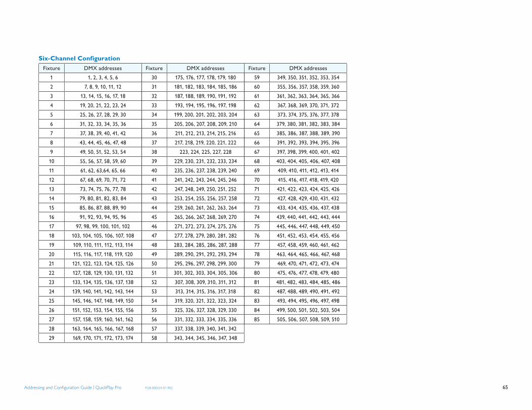
65Addressing and Confi guration Guide | QuickPlay Pro PUB-000224-01 R02
Fixture DMX addresses1 1, 2, 3, 4, 5, 62 7, 8, 9, 10, 11, 123 13, 14, 15, 16, 17, 184 19, 20, 21, 22, 23, 245 25, 26, 27, 28, 29, 306 31, 32, 33, 34, 35, 367 37, 38, 39, 40, 41, 428 43, 44, 45, 46, 47, 489 49, 50, 51, 52, 53, 5410 55, 56, 57, 58, 59, 6011 61, 62, 63,64, 65, 6612 67, 68, 69, 70, 71, 7213 73, 74, 75, 76, 77, 7814 79, 80, 81, 82, 83, 8415 85, 86, 87, 88, 89, 9016 91, 92, 93, 94, 95, 9617 97, 98, 99, 100, 101, 10218 103, 104, 105, 106, 107, 10819 109, 110, 111, 112, 113, 11420 115, 116, 117, 118, 119, 12021 121, 122, 123, 124, 125, 12622 127, 128, 129, 130, 131, 13223 133, 134, 135, 136, 137, 13824 139, 140, 141, 142, 143, 14425 145, 146, 147, 148, 149, 15026 151, 152, 153, 154, 155, 15627 157, 158, 159, 160, 161, 16228 163, 164, 165, 166, 167, 16829 169, 170, 171, 172, 173, 174
Fixture DMX addresses30 175, 176, 177, 178, 179, 18031 181, 182, 183, 184, 185, 18632 187, 188, 189, 190, 191, 19233 193, 194, 195, 196, 197, 19834 199, 200, 201, 202, 203, 20435 205, 206, 207, 208, 209, 21036 211, 212, 213, 214, 215, 21637 217, 218, 219, 220, 221, 22238 223, 224, 225, 227, 22839 229, 230, 231, 232, 233, 23440 235, 236, 237, 238, 239, 24041 241, 242, 243, 244, 245, 246 42 247, 248, 249, 250, 251, 25243 253, 254, 255, 256, 257, 25844 259, 260, 261, 262, 263, 26445 265, 266, 267, 268, 269, 27046 271, 272, 273, 274, 275, 27647 277, 278, 279, 280, 281, 28248 283, 284, 285, 286, 287, 28849 289, 290, 291, 292, 293, 29450 295, 296, 297, 298, 299, 30051 301, 302, 303, 304, 305, 30652 307, 308, 309, 310, 311, 31253 313, 314, 315, 316, 317, 31854 319, 320, 321, 322, 323, 32455 325, 326, 327, 328, 329, 330 56 331, 332, 333, 334, 335, 33657 337, 338, 339, 340, 341, 34258 343, 344, 345, 346, 347, 348
Fixture DMX addresses59 349, 350, 351, 352, 353, 35460 355, 356, 357, 358, 359, 36061 361, 362, 363, 364, 365, 36662 367, 368, 369, 370, 371, 37263 373, 374, 375, 376, 377, 37864 379, 380, 381, 382, 383, 38465 385, 386, 387, 388, 389, 39066 391, 392, 393, 394, 395, 39667 397, 398, 399, 400, 401, 40268 403, 404, 405, 406, 407, 40869 409, 410, 411, 412, 413, 41470 415, 416, 417, 418, 419, 42071 421, 422, 423, 424, 425, 42672 427, 428, 429, 430, 431, 43273 433, 434, 435, 436, 437, 43874 439, 440, 441, 442, 443, 44475 445, 446, 447, 448, 449, 45076 451, 452, 453, 454, 455, 45677 457, 458, 459, 460, 461, 46278 463, 464, 465, 466, 467, 46879 469, 470, 471, 472, 473, 47480 475, 476, 477, 478, 479, 48081 481, 482, 483, 484, 485, 48682 487, 488, 489, 490, 491, 49283 493, 494, 495, 496, 497, 49884 499, 500, 501, 502, 503, 50485 505, 506, 507, 508, 509, 510
Six-Channel Configuration

66Addressing and Confi guration Guide | QuickPlay Pro PUB-000224-01 R02
Appendix B: Addressing Tools Quick ReferenceUse the following table to identify addressing methods for common system configurations:
Fixture Type Nodes Powered By MethodColorBlast® 6 Chromacore 1 PDS-150e Fixture ToolColorBlast® 12 Chromacore 1 PDS-150e Fixture ToolColorBlast® Powercore
Chromacore 1 Data Enabler DMX or Data Enabler Ethernet
Fixture Tool
ColorBlast® TR Chromacore 1 PDS-750 TR OnboardColorBlaze® Chromacore 1 – 12 Onboard OnboardColorBurst® 6 Chromacore 1 Data Enabler DMX Fixture ToolColorBurst® Powercore
Chromacore 1 Data Enabler DMX orData Enabler Ethernet
Fixture Tool
ColorGraze™ Powercore
Chromacore 2 – 4 Data Enabler DMX or Data Enabler Ethernet
Fixture Tool
ColorReach™ Powercore
Chromacore 1 – 2 Data Enabler DMX or Data Enabler Ethernet
Fixture Tool
C-Splash 2 Chromacore 1 PDS-150e Fixture TooleW® Flex SLX Chromasic 50 PDS-60ca 24V DMX PDS TooliColor® Accent Powercore
Chromasic Variable Data Enabler EO PDS Tool
iColor Cove® EC Chromasic 1 sPDS-60ca 24V DMX /Ethernet
Onboard
iColor Cove® MX Powercore
Chromacore 1 Data Enabler DMX or Data Enabler Ethernet
Fixture Tool
iColor Cove® QLX Chromasic 1 sPDS-60ca 24V DMX /Ethernet or sPDS-480ca 24V Ethernet
Onboard
iColor Cove® QLX Chromasic 1 PDS-60ca 24V DMX / Ethernet
PDS Tool
iColor® Flex SL Chromasic 50 PDS-60ca 7.5V DMX /Ethernet
PDS Tool
iColor® Flex SL Chromasic 50 sPDS-480ca 7.5V Ethernet
Onboard
iColor® Flex SLX Chromasic 50 PDS-60ca 12V DMX /Ethernet
PDS Tool
iColor® Flex SLX Chromasic 50 sPDS-480ca 12V Ethernet
Onboard
Fixture Type Nodes Powered By MethodiColor® Module FX Chromasic 9 / 36 PDS-60ca 7.5V DMX /
EthernetPDS Tool
iColor® MR g2 Chromacore 1 PDS-70mr 24v DMX or PDS-70mr 24v Ethernet
Fixture Tool
iColor® Tile FX 2:2 Chromasic 144 PDS-60ca 7.5V DMX /Ethernet
PDS Tool
iW™ Blast Powercore Chromacore 1 Data Enabler DMX or Data Enabler Ethernet
Fixture Tool
iW™ Blast TR Chromacore 1 PDS-750 TR OnboardiW™ Cove Powercore Chromacore 1 Data Enabler DMX or
Data Enabler EthernetFixture Tool
iW™ Profile g2 Chromacore 1 PDS-150e Fixture Tool
Note: Addressing and configuration is optional for eW and iW fixtures.

67Addressing and Confi guration Guide | QuickPlay Pro PUB-000224-01 R02
Appendix C: CKDMX / ESTA DMX Crossover CableA CKDMX to ESTA DMX crossover cable is required when using non-CKDMX controllers with RJ-45 DMX output ports in conjunction with fixtures and Power / Data Supplies from Philips Color Kinetics. The crossover cable installs inline between the controller and the first Power / Data Supply in the DMX lighting installation.
Pin Assignments
CKDMX Male Connector Pin
Assignment
ESTA Female Connector Pin
Assignment8 67 36 85 54 43 72 11 2
Appendix D: 16-bit DMX Channel MappingCertain fixtures from Philips Color Kinetics can be programmed for 16-bit control. 16-bit programming utilizes two DMX channels per LED channel; for example, two DMX channels for red, two DMX channels for green, and two DMX channels for blue.
The first DMX channel assigned to an LED channel corresponds to the “coarse” data for that LED channel. The second DMX channel corresponds to the “fine” data for that LED channel.
Utilizing both coarse and fine DMX channels for each LED channel increases resolution from 256 dimming steps per LED channel to 65536 dimming steps per LED channel.
Note that fixtures programmed for 16-bit output use double the quantity of DMX channels compared to fixtures configured for 8-bit output. Only select the 16-bit programming option if you are using a 16-bit compatible controller.
Example: RGB 16-bit DMX Channel Mapping
DMX address LED Channel Course / Finen Red Coarse
n + 1 Red Finen + 2 Green Coarsen + 3 Green Finen + 4 Blue Coarsen + 5 Blue Fine
Example: ColorReach PowerCore Channel Totals
DMX Channel Totals
Mode
3 Full 8-bit6 Half 8-bit6 Full 16-bit12 Half 16-bit

Philips Color Kinetics3 Burlington Woods DriveBurlington, Massachusetts 01803 USATel 888.Full.RGBTel 617.423.9999Fax 617.423.9998www.colorkinetics.com
Copyright © 2008-2009 Philips Solid-State Lighting Solutions, Inc. All rights reserved.
Chromacore, Chromasic, CK, the CK logo, Color Kinetics, the Color Kinetics logo, ColorBlast, ColorBlaze, ColorBurst, ColorGraze, ColorPlay, ColorReach,
DIMand, EssentialWhite, eW, iColor, iColor Cove, IntelliWhite, iW, iPlayer, Light Without Limits, Optibin, and Powercore are either registered trademarks or
trademarks of Philips Solid-State Lighting Solutions, Inc. in the United States and/or other countries. All other brand or product names are trademarks or
registered trademarks of their respective owners. Due to continuous improvements and innovations, specifications may change without notice.
PUB-000224-01 R02 07-09