Embed Size (px)
Citation preview

National Aeronautics and Space Administration
www.nasa.gov 1
Additive Manufacturing of Multi-Material Systems for Aerospace Applications
Michael C. Halbig1 and Mrityunjay Singh2
1-NASA Glenn Research Center, Cleveland, OH
2-Ohio Aerospace Institute, Cleveland, OH
MS&T19 - Materials Science & Technology 2019 Portland, OR, September 29 to October 3, 2019.

National Aeronautics and Space Administration
www.nasa.gov 2
Outline• Needs, challenges, and applications • AM of multi-materials in a single feed-stock
– Direct writing of low resistance conductors– Binder jet printing of SiC fiber / SiC matrix composites– FDM of polymer-based materials with functional additions
• Hybrid and two-stage AM toward multi-material components– Stators for electric motors– Lightweight multi-functional components, e.g. thermal
management of battery packs• Summary and Conclusions

National Aeronautics and Space Administration
www.nasa.gov 3
Additive Manufacturing of Multi-MaterialsNeeds:• Achieving complex shapes and processing not possible from conventional
fabrication methods.• Components with integrated sub-elements of differing materials and structures.• Tailored material properties: e.g. microstructure, mechanical, electrical, thermal,
and magnetic.
Challenges:• Additive manufacturing for multi-materials is not as mature as for single materials.• Optimal utilization of several methods, e.g. single machine AM, multi-machine
AM, and hybrid approaches (combinations of AM and conventional).• Post-processing of multi-materials with differing sintering temperatures and
material mismatches and incompatibilities.

National Aeronautics and Space Administration
www.nasa.gov
Components for Aerospace ApplicationsTurbine Engines -
Targeted Components (CMCs and PMCs)
Radial Flux Machine
Axial Flux MachineHousing
RotorMagnet(s)Stator
Electric Motors-Targeted Components (structural,
functional, and electrical)
4
Fan DuctShrouds &
Vanes
Exhaust Components
Combustor Liners
AM for In-Space and on Terrestrial Planets -Targeted Components (Functional PMCs)
Replacement Part FabricationLightweight Multifunctional
Components

National Aeronautics and Space Administration
www.nasa.gov
Fused Deposition ModelingPlastic is heated and supplied through an extrusion nozzle and deposited.
Binder JettingAn inkjet-like printing head moves across a bed of powder and deposits a liquid binding material.
Direct Write PrintingControlled dispensing of inks, pastes, and slurries.
Additive Manufacturing Technologies
5

National Aeronautics and Space Administration
www.nasa.gov 6
Outline• Needs, challenges, and applications • AM of multi-materials in a single feed-stock
– Direct writing of low resistance conductors– Binder jet printing of SiC fiber / SiC matrix composites– FDM of polymer-based materials with functional additions
• Hybrid and two-stage AM toward multi-material components– Stators for electric motors– Lightweight functional components, e.g. thermal
management of battery packs• Summary and Conclusions

National Aeronautics and Space Administration
www.nasa.gov
Direct Writing of Low Resistance Conductors
7
Additions of Graphene and Carbon Nanostructures
Most Conductive CompositesPaste Composition Resistivity
[Ωm]Conductivity [Ωm]^-1
CB028 + 0.2 wt% QUATTRO Graphene
8.14798E-08 1.23E+07
Heraeus + 0.04 wt% CNS 8.29725E-08 1.21E+07
CB028 + 0.1 wt% QUATTRO Graphene
1.03586E-07 9.65E+06
CB028 + 0.085 wt% CNS 1.1145E-07 8.97E+06
Heraeus + 0.14 wt% CNS 1.19059E-07 8.40E+06
CB028 + 0.2 wt% MONO Graphene
1.26118E-07 7.93E+06
CB028 + 0.5 wt% MONOGraphene
1.41875E-07 7.05E+06
Plain PastesPaste Composition Resistivity
[Ωm]Conductivity [Ωm]^-1
Plain CB028 2.82 E-08 3.54 E+07
Plain Heraeus 4.12384E-08 2.42E+07Substrate
Silver paste
nScrypt 3Dn-300
4-point probe method
Peng-Cheng Ma, “Enhanced Electrical Conductivity of Nanocomposites Containing Hybrid Fillers of Carbon Nanotubes and Carbon Black
Y. Kim, et al. U.S. Patent 8,481,86, 2013 –Conductive Paste Containing Silver Decorated CNT

National Aeronautics and Space Administration
www.nasa.gov 8
Binder Jetting of SiC Fiber / SiC Matrix CompositesExOne Innovent
Fiber Reinforced Ceramic Matrix Composite
High pressure turbine cooled doublet vane sections.
Si-TUFF iSiC fbers(Advanced Composite Materials, LLC)
Constituents
SiC powder loaded SMP-10
SiC powder
SiC powder
~70 µm long and ~7 µm in diameter

National Aeronautics and Space Administration
www.nasa.gov
Binder Jetting: Density of SiC Panels
1.40
1.50
1.60
1.70
1.80
1.90
2.00
2.10
2.20
Dens
ity (g
/cc)
Density at as-processed through 1, 2, and 3 infiltrations
I5
N5
O5
G5
P6
Q6
0 321
Densities increased by up to 33% from additional PCS infiltration steps and were maintained even at higher SiC fiber loadings of 45, 55, and 65 vol.%.
2”x2” CMC coupons
Polymer approach has a limitation on achievable densities.
Melt infiltration methods such, e.g. silicon melt, can achieve near full density.
Multiple PCS infiltration steps.
45 vol. % Si Tuff fiber
65 vol. % Si Tuff fiber
55 vol. % Si Tuff fiber
75 vol. % Si Tuff fiber
9
Demonstration of full densification through silicon melt-infiltration.
SiCSiC
Silicon infiltration
SiC

National Aeronautics and Space Administration
www.nasa.gov 10
Carborex Powder mix with 65 vol.% Si-Tough SiC fiber, SMP-10 w/800 nano SiC particles vacuum infiltration.
Binder Jetting: Cross-Section and Fracture Surface from SiC/SiC Sample with 65 vol.% SiC Fiber
Good densities achieved with high fiber loading.

National Aeronautics and Space Administration
www.nasa.gov
Binder Jetting: 4 Point Flexure Tests of the Monolithic SiC and CMC materials - at room
temperature and 1200°C
0
10
20
30
40
50
60
70
80
0.00 0.02 0.04 0.06 0.08 0.10
Stre
ss (M
Pa)
Strain (%)
Non-Reinforced SiC - Set G
0
10
20
30
40
50
60
70
80
0.00 0.02 0.04 0.06 0.08 0.10
Stre
ss (M
Pa)
Strain (%)
65 vol. % SiC Fiber Reinforced SiC - Set N
The fiber loaded SiC materials had significantly higher stresses and higher strains to failure.
Bend bars for strength testing
11

National Aeronautics and Space Administration
www.nasa.gov 12
0.1 mm
0.4 mm
Highest strength and modulus in CNT reinforced couponsPure ABS Coupons. Less porosity for lower print heights.
Effect of print layer height
FDM of Composite Filaments for Multi-Functional ApplicationsPotential Missions/Benefits:• On demand fabrication of as needed functional components in space• Tailored, high strength, lightweight support structures reinforced with CNT• Tailored facesheets for functional properties, i.e. wear resistance, vibration dampening, radiation shielding, acoustic attenuation, thermal management
Color Fab, copper fill metal, PLA
Proto Pasta, Magnetic iron,
PLA
GMASS, Tungsten, ABS
GMASS, Bismuth, ABS
C-Fiber Reinforced ABS Filaments
Filaments used: ABS-standard abs, P-premium abs, CNT-w/carbon nanotubes, C-w/chopped carbon, Home-lab extruded filament

National Aeronautics and Space Administration
www.nasa.gov 13
Outline• Needs, challenges, and applications • AM of multi-materials in a single feed-stock
– Direct writing of low resistance conductors– Binder jet printing of SiC fiber / SiC matrix composites– FDM of polymer-based materials with functional additions
• Hybrid and two-stage AM toward multi-material components– Stators for electric motors– Lightweight functional components, e.g. thermal
management of battery packs• Summary and Conclusions

National Aeronautics and Space Administration
www.nasa.gov 14
AM and Hybrid Approaches for Electric Motor Components
Components of a Commercial Axial Flux Motor
NASA Electric Motor with AM Components
Additively Manufactured Rotor Plate
Rotor Constituents: • Permanent magnets.• High strength structure
(typically metallic).
PCB Coreless StatorLitz WireCoreless Stator
Stator Constituents: • Conductor: copper,
silver.• Insulators: coatings,
dielectrics, epoxy, high temp. polymer.
• Soft magnets (for cores): iron alloys.
Iron Core Stator with Direct Printed Coils
Electric Motors Stators Rotors

National Aeronautics and Space Administration
www.nasa.gov
Ultrasonic embedding horn
20 kHz Ultrasonic
system
Cartridge heated embedding demonstration
PC substrate
Wire Embedded Stator: U. of Texas El Paso (NASA CAMIEM)
15
• Challenges with feeding wire through ultrasonic horn of required 14 AWG wire.
• Challenges with overprinting polycarbonate onto embedded wire.
press
Pressing process needed to further densify the stator
Final stator
Conventional stator by LaunchPoint Technologies
Multi3D System
FDM Machine 1
FDM Machine 2
CNC router capable of: • Machining• Direct-write• Wire embedding• Robotic component
placement
Six-axis robot arm (Yaskawa
MotomanMH50)
Workpiece
National Aeronautics and Space Administration
www.nasa.gov
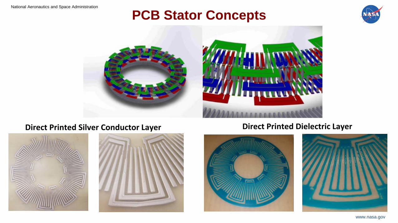
PCB Stator Concepts
Direct Printed Silver Conductor Layer Direct Printed Dielectric Layer

National Aeronautics and Space Administration
www.nasa.gov
Direct Printed Stator - Concepts A and BBenefits – Higher magnetic flux, torque, and motor constant (Km). – Higher temp. capability of >220°C instead of 160°C for baseline stator.– Direct printed silver coils with high fill.
Stator Plate from Cobalt-Iron Alloy
Cirlex Middle Layer
Outer Rings17
Concept A
Details of machined features
Substrate
Silver paste
nScrypt 3Dn-300
4-point probe method
Direct Printed Silver Coils -High Current Test

National Aeronautics and Space Administration
www.nasa.gov
Additively Manufactured Stator Plates
FDM from Extem (Tg of 311°C) (left) and Ultem1010 (TG of 217°C) (right) FDM filament.
Low cost and rapidly manufactured sub-components may be possible with further advancements or alternate AM processes. 18
FDM Process
Stator Plate from Cobalt-Iron Alloy
1200°C – 51.3% TD
500 μm
High Temp. Polymer
Soft Magnet
Binder Jetting

National Aeronautics and Space Administration
www.nasa.gov 19
Fabrication Method Machine/EDM Machine/MillFabrication Time 4+ months 3 months
Fabrication Costs $21,400 $19, 870Material Costs $600 $330Total Costs $22,000 $20,200
Comparison of Methods to Obtain Outside Fabrication for Channeled Plates for Stators
Concept B - Stator Plates from Ultem1010
Concept B - Stator Plates from Cirlex
Concept A - Stator Plates from Cobalt-Iron Alloy
3D Print/FDM1 week (92.3% reduction)
$1,000$0 (included in fab.)$1,000 (95.0% reduction)
Currently relying on machined stator plates.

National Aeronautics and Space Administration
www.nasa.gov 20
Premium ABS(P-ABS)
5% Carbon Fiber by weight ABS
(CF-ABS)
FDM of Multi-Material Test Coupons for Lightweight Multi-Functional Applications
(upside down) (upside down)
System A• Half P-ABS• Half CF-ABS• P-ABS bottom
System B• Half P-ABS• Half CF-ABS• CF-ABS bottom
System D• 8 alternating layers of
P-ABS and CF-ABS• CF-ABS bottom
System C• 4 alternating layers of
P-ABS and CF-ABS• CF-ABS bottom

National Aeronautics and Space Administration
www.nasa.gov 21
Microstructures of FDM of Multi-Material Test CouponsSystem A
System B
(upside down)
System C
System DP-ABS
CF-ABS

National Aeronautics and Space Administration
www.nasa.gov 22
Multi-Material Tensile Testing
Multi-material print Tensile Testing
(DIC)
FDM Process
Hyrel Hydra 645

National Aeronautics and Space Administration
www.nasa.gov 23
Material LetterMax Load
[N]Avg Load
[N] Max Ult [Mpa] Avg Ult [Mpa] Max Mod Avg Mod Avg STF3DXTech Ultem 9085 CF H 1992.1 1893.4 53.7 50.5 3380.5 3204.2 1.8974SABIC ULTEM AM9085F P 3163.6 2988.7 77.5 74.5 2395.3 2261.5 7.5265SABIC 9085+3DXTech 9085 CF PH 2679.0 2480.6 62.4 59.1 3082.6 3005.3 2.5691
SABIC 9085 + 3DXTech 9085 CF
3DXTech Ultem 9085 CF
SABIC 9085 Single and Multi-Material Tensile Testing
122122121212121212122122111222111222
1=3DXTech Ultem 9085 CF2=SABIC ULTEM AM9085F

National Aeronautics and Space Administration
www.nasa.gov 24
Multi-Material Heat Exchanger Designs
Single Material Battery Case Demostrations
Forced Air Cooled Liquid Cooled

National Aeronautics and Space Administration
www.nasa.gov
Conclusions• Additive manufacturing enables advanced materials, structures,
and components.
• AM of multi-materials in a single feed-stock allows for optimized properties and functionality, e.g. electrical conductivity, thermal conductivity, strength, etc.
• Achieving multi-material components requires hybrid and two-stage AM approaches.
Acknowledgments: the research was supported by NASA Projects: CAS/CAMIEM, TTT, CIF. Thanks to the Summer Interns.