Embed Size (px)
Citation preview
U.Porto Journal of Engineering, 7:3 (2021) 53-69 ISSN 2183-6493 DOI: 10.24840/2183-6493_007.003_0005
Received: 27 November, 2020 Accepted: 2 January, 2021
Published: 30 April, 2021
53
Additive Manufacturing: Material Extrusion of Metallic Parts
J. M. Costa1, E. W. Sequeiros2, M. T. Vieira3, M. F. Vieira4 1Department of Metallurgical and Materials Engineering, Faculty of Engineering, University of Porto; LAETA/INEGI - Institute of Science and Innovation in Mechanical and Industrial Engineering, Rua Dr. Roberto Frias, 4200-465 PORTO, Portugal ([email protected]) ORCID 0000-0002-1714-4671; 2Department of Metallurgical and Materials Engineering, Faculty of Engineering, University of Porto; LAETA/INEGI - Institute of Science and Innovation in Mechanical and Industrial Engineering, Rua Dr. Roberto Frias, 4200-465 PORTO, Portugal ([email protected]) ORCID 0000-0002-5295-5648; 3CEMMPRE, Department of Mechanical Engineering, University of Coimbra, Portugal ([email protected]) ORCID 0000-0001-9981-3826; 4Department of Metallurgical and Materials Engineering, Faculty of Engineering, University of Porto; LAETA/INEGI - Institute of Science and Innovation in Mechanical and Industrial Engineering, Rua Dr. Roberto Frias, 4200-465 PORTO, Portugal ([email protected]) ORCID 0000-0002-3667-0562
Abstract Additive manufacturing (AM) is one of the most trending technologies nowadays, and it has the potential to become one of the most disruptive technologies for manufacturing. Academia and industry pay attention to AM because it enables a wide range of new possibilities for design freedom, complex parts production, components, mass personalization, and process improvement. The material extrusion (ME) AM technology for metallic materials is becoming relevant and equivalent to other AM techniques, like laser powder bed fusion. Although ME cannot overpass some limitations, compared with other AM technologies, it enables smaller overall costs and initial investment, more straightforward equipment parametrization, and production flexibility. This study aims to evaluate components produced by ME, or Fused Filament Fabrication (FFF), with different materials: Inconel 625, H13 SAE, and 17-4PH. The microstructure and mechanical characteristics of manufactured parts were evaluated, confirming the process effectiveness and revealing that this is an alternative for metal-based AM.
Author Keywords. Additive Manufacturing, Material Extrusion, Fused Filament Fabrication, Metallic Materials Filaments, Feedstocks.
Type: Research Article
Open Access Peer Reviewed CC BY
1. Introduction
Additive manufacturing (AM) is a disruptive process, and the understanding of its structure and properties is essential to comprehend what happens at the microstructural level (Wang et al. 2018a). AM enables the end-user to design, create, develop, and fabricate with versatility and flexibility, disrupting conventional/traditional fabrication principles on personal or corporate levels (DebRoy et al. 2018; Frazier 2014; Herderick 2011).
Commonly denominated as "3D printing", the first applications of AM were used initially for prototyping (Atzeni and Salmi 2015). Quickly it was understood its potential as an effective process, to be used from upstream to downstream (Mellor, Hao, and Zhang 2014; Gibson et al. 2018). From the fabrication of prototypes in the development phase, tooling, and customers end product (Gibson, Rosen, and Stucker 2015), and allows the manufacturing of
Additive Manufacturing: Material Extrusion of Metallic Parts J. M. Costa, E. W. Sequeiros, M. T. Vieira, M. F. Vieira
U.Porto Journal of Engineering, 7:3 (2021) 53-69 54
highly customized products, with total freedom of design, and using complex shapes. The American Society for Testing and Materials (ASTM) defines AM as a process of joining materials to make objects from 3D model data, usually layer upon layer, as opposed to subtractive manufacturing methodologies (ASTM 2012).
The AM processes comprise high-end and digital technology (on hardware, software, and processes) and referenced as a technological path for the manufacturing world's future (Tofail et al. 2018; Leach et al. 2019). It cannot be dissociated from the new industrial paradigm since it can increase efficiency and productivity while ensuring a circular economy improvement. AM processes are intrinsic to parts of the product development process and enable a new perception of manufacturing components with complex shapes and integrated parts (Atzeni and Salmi 2015). A continued equipment development for full manufacturing readiness and understanding of the materials processes is essential to accomplish the AM potential (Herderick 2011). One of the mandatory requirements to achieve an effective joining in AM, independently of the selected technology, is to have an effective combination of the feedstock (or raw) material and good energy delivery (Thompson et al. 2015).
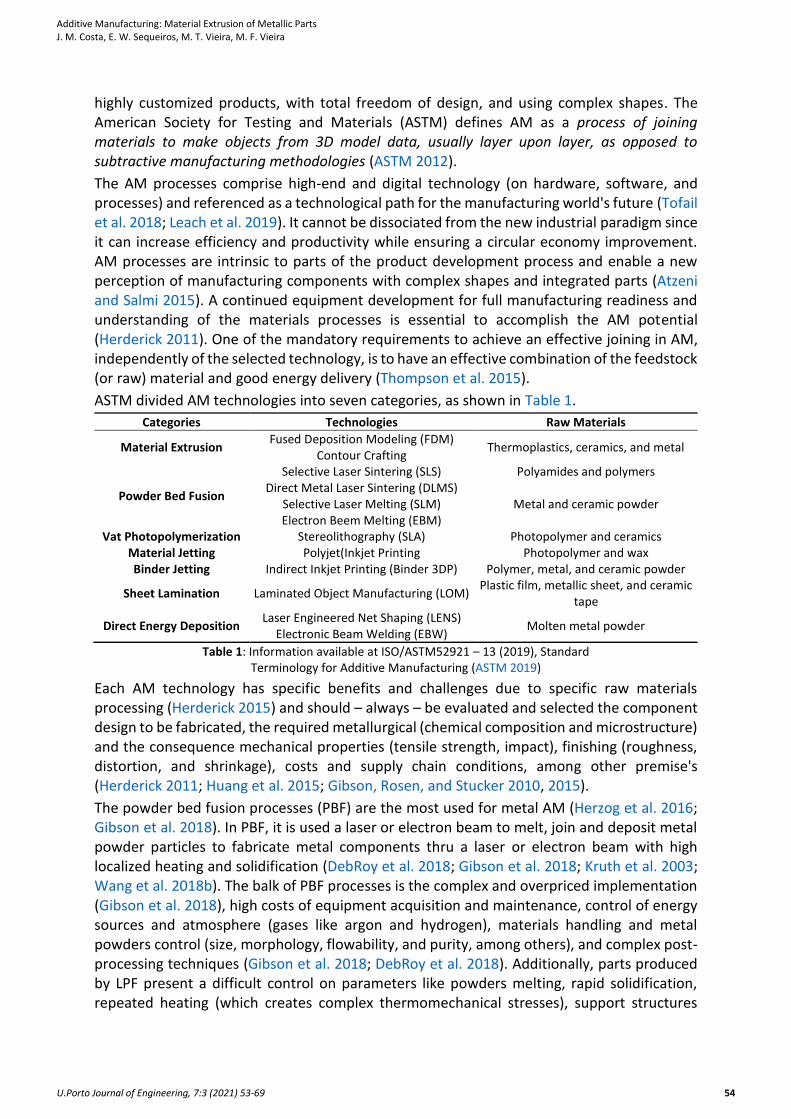
ASTM divided AM technologies into seven categories, as shown in Table 1.
Categories Technologies Raw Materials
Material Extrusion Fused Deposition Modeling (FDM)
Contour Crafting Thermoplastics, ceramics, and metal
Powder Bed Fusion
Selective Laser Sintering (SLS) Polyamides and polymers Direct Metal Laser Sintering (DLMS)
Metal and ceramic powder Selective Laser Melting (SLM) Electron Beem Melting (EBM)
Vat Photopolymerization Stereolithography (SLA) Photopolymer and ceramics Material Jetting Polyjet(Inkjet Printing Photopolymer and wax Binder Jetting Indirect Inkjet Printing (Binder 3DP) Polymer, metal, and ceramic powder
Sheet Lamination Laminated Object Manufacturing (LOM) Plastic film, metallic sheet, and ceramic
tape
Direct Energy Deposition Laser Engineered Net Shaping (LENS)
Electronic Beam Welding (EBW) Molten metal powder
Table 1: Information available at ISO/ASTM52921 – 13 (2019), Standard Terminology for Additive Manufacturing (ASTM 2019)
Each AM technology has specific benefits and challenges due to specific raw materials processing (Herderick 2015) and should – always – be evaluated and selected the component design to be fabricated, the required metallurgical (chemical composition and microstructure) and the consequence mechanical properties (tensile strength, impact), finishing (roughness, distortion, and shrinkage), costs and supply chain conditions, among other premise's (Herderick 2011; Huang et al. 2015; Gibson, Rosen, and Stucker 2010, 2015).
The powder bed fusion processes (PBF) are the most used for metal AM (Herzog et al. 2016; Gibson et al. 2018). In PBF, it is used a laser or electron beam to melt, join and deposit metal powder particles to fabricate metal components thru a laser or electron beam with high localized heating and solidification (DebRoy et al. 2018; Gibson et al. 2018; Kruth et al. 2003; Wang et al. 2018b). The balk of PBF processes is the complex and overpriced implementation (Gibson et al. 2018), high costs of equipment acquisition and maintenance, control of energy sources and atmosphere (gases like argon and hydrogen), materials handling and metal powders control (size, morphology, flowability, and purity, among others), and complex post-processing techniques (Gibson et al. 2018; DebRoy et al. 2018). Additionally, parts produced by LPF present a difficult control on parameters like powders melting, rapid solidification, repeated heating (which creates complex thermomechanical stresses), support structures
Additive Manufacturing: Material Extrusion of Metallic Parts J. M. Costa, E. W. Sequeiros, M. T. Vieira, M. F. Vieira
U.Porto Journal of Engineering, 7:3 (2021) 53-69 55
construction (used to enable production layer-by-layer and resist deformations), and complicated post-processing to achieve dimensionally accurate parts (Kruth et al. 2005; Wu et al. 2014; Zeng et al. 2015; Gibson et al. 2018).
Alternative technologies are currently under development, where the main objective is to create an accessible technology to enable metal AM. The ME process, well known from polymer AM processes, figures as a potential alternative to PBF (DebRoy et al. 2018; Gibson, Rosen, and Stucker 2010; Gonzalez-Gutierrez et al. 2018b). The key features for any metal-based ME is the loading and melting of the metal filament, adequate pressure to move material thru nozzle, enable controlled extrusion in the correct place, and coherent bonding of the material extruded to create a solid structure (Gibson, Rosen, and Stucker 2010; Singh, Ramakrishna, and Singh 2017). As in other metal AM processes, deposition strategies (material quantities, density, and rastering), support structures, scaffold architectures, among others, are defined by specific software, using the component CAD 3D file (Rane and Strano 2019; Kumar et al. 2018; Thompson et al. 2016; Singh, Ramakrishna, and Singh 2017). This type of software can define the path for the deposition of material layer-by-layer (slicing) and define the printing parameters such as layer thickness, the number of shells, pattern, raster gap, print speed, and others (Kumar et al. 2018; Al and Yaman 2017; Gao et al. 2015).
The metal-based ME technology requires four distinct steps: (1) the filament production and characterization, (2) production of AM component using the filament extrusion process, (3) debinding, and (4) sintering.
The production of filaments for metal-based ME is one of the most critical phases of this technology. A proper choice of the materials to be used (metallic powder, binder, and additives) is required for the successful production of components. The filaments used in metal-based ME result from the extrusion of feedstock, a mixture of metallic powders combined with a specific concentration of a polymeric binder system, in the correct proportions (usually 60% metallic and 40% polymer feedstocks). The purpose of the mixture, similar to metal hot embossing and metal injection molding (MIM), is to disperse the metal powder in the binder, avoiding internal porosity and agglomeration, which enables a homogeneous biphasic mixture (Sequeiros et al. 2020; Singh et al. 2019b; Gonzalez-Gutierrez et al. 2018b). The powder characteristics influence the filament's rheological behavior in its production and metal ME processes. Ideally, filament characterization should comprise particle size distribution (PSD), morphology, density, specific surface area, and interaction between particles (Sequeiros et al. 2015; Singh et al. 2019a; Royer, Barriere, and Gelin 2016).
The filament production is one of the most challenging operations, where the selected process parameters must be appropriated to the mixture and extrusion system used and preliminary optimized for each filament. An excellent mixture must be homogeneous, with a good shape and a stable diameter dimension. Usually, they are extruded into a spool and usually have a 1,75 mm diameter. Combining a suitable feedstock and extrusion enables a stable and effective (and profitable) ME process. It is also possible to find several types of metallic filaments for ME in the market, and the filaments' characterization is mandatory to understand their characteristics (and see if they accomplish requirements for manufacturing).
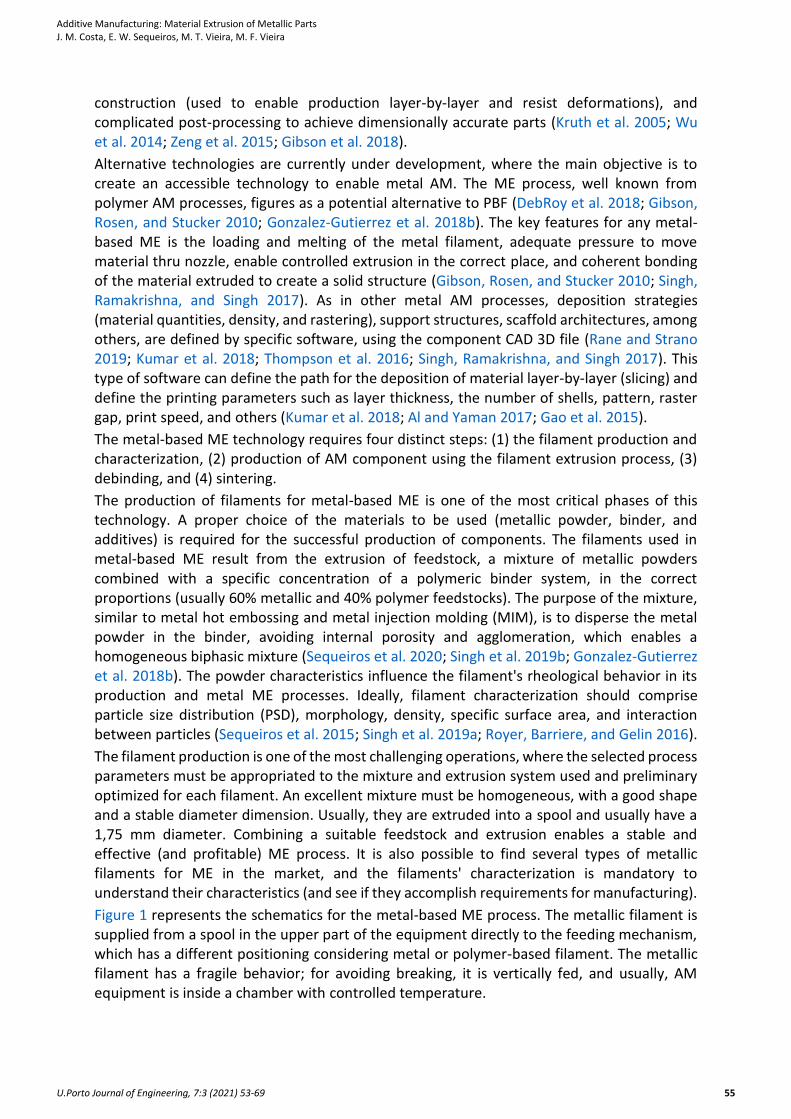
Figure 1 represents the schematics for the metal-based ME process. The metallic filament is supplied from a spool in the upper part of the equipment directly to the feeding mechanism, which has a different positioning considering metal or polymer-based filament. The metallic filament has a fragile behavior; for avoiding breaking, it is vertically fed, and usually, AM equipment is inside a chamber with controlled temperature.
Additive Manufacturing: Material Extrusion of Metallic Parts J. M. Costa, E. W. Sequeiros, M. T. Vieira, M. F. Vieira
U.Porto Journal of Engineering, 7:3 (2021) 53-69 56
Before production, it is required to design components to be produced with CAD 3D software. After the component design, slicing software is used to define the manufacturing strategy. This software will convert the CAD 3D in a set of paths (coordinates X, Y, and Z), and layer upon layer will enable to trace designed component and manufacture it. Usually, these slicing software enable the optimization and parametrization of several properties, impacting final component finishing, and overall quality.
Figure 1: Schematics for metal-based ME equipment
The filament enters the extrusion head, where it is heated to a viscous state and is deposited in the building plate. According to the slicing strategy, the material goes through the nozzle, turning on and off the material's extrusion. These equipment types work in X, Y, and Z axes and draw layers according to the software coordinates; when the equipment ends a layer, it starts the upper layer. The deposition will be from bottom to top of the component, and the material solidifies, stacking the upper and the lower layers, creating a component. During manufacturing, the nozzle is extruding material for the component and the builds support structures; the build supports enable overhang geometries, automatically created by the slicing software, and to be removed after finishing manufacturing (Singh, Ramakrishna, and Singh 2017; Kumar et al. 2018; Hertle et al. 2020; Gao et al. 2015). The component fabricated thru metal ME is commonly described as Green Part.
The debinding and sintering enable the densification of the ME produced component and are crucial for getting components with comparable properties to other AM technologies (like PBF or binder jetting process). Both processes are – usually – carried in vacuum furnaces (Kurose et al. 2020).
The optimization of debinding depends on the characteristics of the binder system and components. Several debinding techniques exist, like solvent debinding, catalytic treatment, thermal treatment, or a combination of two or more (Sequeiros et al. 2020). The objective of debinding is to gradually remove the binder materials to keep the manufactured components' shape (Singh et al. 2019b). Brown parts, designation after debinding, require a graduate removal of binder to avoid defects (Sequeiros et al. 2020; Gonzalez-Gutierrez et al. 2018b) and shape loss due to the removal of the binder. Poor debinding conditions can impact the components' porosity since carbon residues can influence the sintering process, promoting
Additive Manufacturing: Material Extrusion of Metallic Parts J. M. Costa, E. W. Sequeiros, M. T. Vieira, M. F. Vieira
U.Porto Journal of Engineering, 7:3 (2021) 53-69 57
bloating, blistering, surface cracking, and large internal voids, which will increase the difficulty of achieving a highly dense component (Gonzalez-Gutierrez et al. 2018a).
The last step of getting a dense metal component is the sintering, where is applied a thermal treatment to the brown part to transforms the metallic powder into a bulk material. The temperature is below the melting point – usually between 70 and 90% – of the metal powder (or the major metallic component) to obtain solid components, with all geometries created in the ME process (Gonzalez-Gutierrez et al. 2018a; Gonzalez-Gutierrez et al. 2018b). Due to the high porosity of components, there is a rearrangement and mass transport during sintering. As temperature increases, the system reduces surface energy, forming solid bonds (or necks) between particles, which continue to grow to decrease porosity and densify the components, resulting in a shrinkage of components (Gonzalez-Gutierrez et al. 2018a). The monitoring and optimization of sintering parameters are critical to getting a proper component. The microstructural evaluation and mechanical characterization are critical to optimizing sintering parameters and enhance component consolidation.
This study will analyze the production with ME technology, using metallic filaments (a superalloy of Nickel – Inconel 625, a tool steel – H13 SAE, and stainless steel – 17-4PH). The microstructural and mechanical characterizations enable the analysis of process effectiveness, comparing the properties of these with conventional materials.
2. Materials and Methods
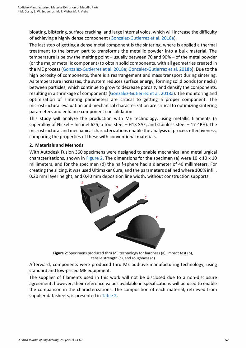
With Autodesk Fusion 360 specimens were designed to enable mechanical and metallurgical characterizations, shown in Figure 2. The dimensions for the specimen (a) were 10 x 10 x 10 millimeters, and for the specimen (d) the half-sphere had a diameter of 40 millimeters. For creating the slicing, it was used Ultimaker Cura, and the parameters defined where 100% infill, 0,20 mm layer height, and 0,40 mm deposition line width, without construction supports.
Figure 2: Specimens produced thru ME technology for hardness (a), impact test (b),
tensile strength (c), and roughness (d)
Afterward, components were produced thru ME additive manufacturing technology, using standard and low-priced ME equipment.
The supplier of filaments used in this work will not be disclosed due to a non-disclosure agreement; however, their reference values available in specifications will be used to enable the comparison in the characterizations. The composition of each material, retrieved from supplier datasheets, is presented in Table 2.
Additive Manufacturing: Material Extrusion of Metallic Parts J. M. Costa, E. W. Sequeiros, M. T. Vieira, M. F. Vieira
U.Porto Journal of Engineering, 7:3 (2021) 53-69 58
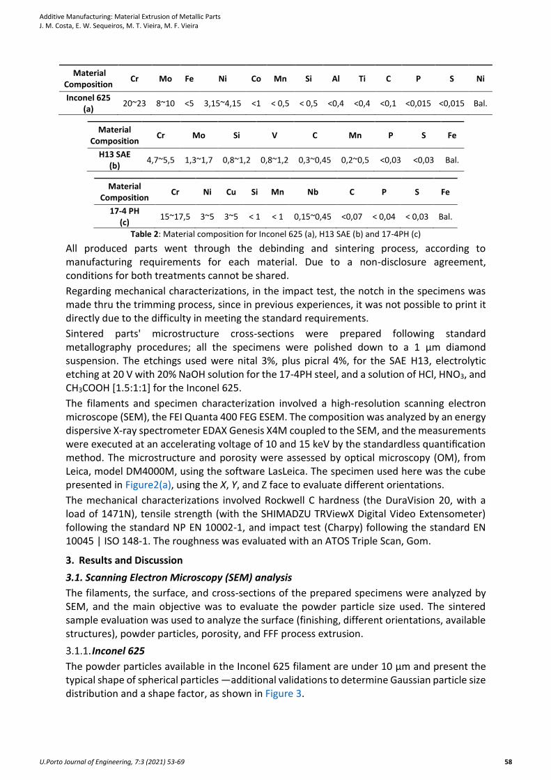
Material Composition
Cr Mo Fe Ni Co Mn Si Al Ti C P S Ni
Inconel 625 (a)
20~23 8~10 <5 3,15~4,15 <1 < 0,5 < 0,5 <0,4 <0,4 <0,1 <0,015 <0,015 Bal.
Material Composition
Cr Mo Si V C Mn P S Fe
H13 SAE (b)
4,7~5,5 1,3~1,7 0,8~1,2 0,8~1,2 0,3~0,45 0,2~0,5 <0,03 <0,03 Bal.
Material Composition
Cr Ni Cu Si Mn Nb C P S Fe
17-4 PH (c)
15~17,5 3~5 3~5 < 1 < 1 0,15~0,45 <0,07 < 0,04 < 0,03 Bal.
Table 2: Material composition for Inconel 625 (a), H13 SAE (b) and 17-4PH (c)
All produced parts went through the debinding and sintering process, according to manufacturing requirements for each material. Due to a non-disclosure agreement, conditions for both treatments cannot be shared.
Regarding mechanical characterizations, in the impact test, the notch in the specimens was made thru the trimming process, since in previous experiences, it was not possible to print it directly due to the difficulty in meeting the standard requirements.
Sintered parts' microstructure cross-sections were prepared following standard metallography procedures; all the specimens were polished down to a 1 µm diamond suspension. The etchings used were nital 3%, plus picral 4%, for the SAE H13, electrolytic etching at 20 V with 20% NaOH solution for the 17-4PH steel, and a solution of HCl, HNO3, and CH3COOH [1.5:1:1] for the Inconel 625.
The filaments and specimen characterization involved a high-resolution scanning electron microscope (SEM), the FEI Quanta 400 FEG ESEM. The composition was analyzed by an energy dispersive X-ray spectrometer EDAX Genesis X4M coupled to the SEM, and the measurements were executed at an accelerating voltage of 10 and 15 keV by the standardless quantification method. The microstructure and porosity were assessed by optical microscopy (OM), from Leica, model DM4000M, using the software LasLeica. The specimen used here was the cube presented in Figure2(a), using the X, Y, and Z face to evaluate different orientations.
The mechanical characterizations involved Rockwell C hardness (the DuraVision 20, with a load of 1471N), tensile strength (with the SHIMADZU TRViewX Digital Video Extensometer) following the standard NP EN 10002-1, and impact test (Charpy) following the standard EN 10045 | ISO 148-1. The roughness was evaluated with an ATOS Triple Scan, Gom.
3. Results and Discussion
3.1. Scanning Electron Microscopy (SEM) analysis
The filaments, the surface, and cross-sections of the prepared specimens were analyzed by SEM, and the main objective was to evaluate the powder particle size used. The sintered sample evaluation was used to analyze the surface (finishing, different orientations, available structures), powder particles, porosity, and FFF process extrusion.
Inconel 625
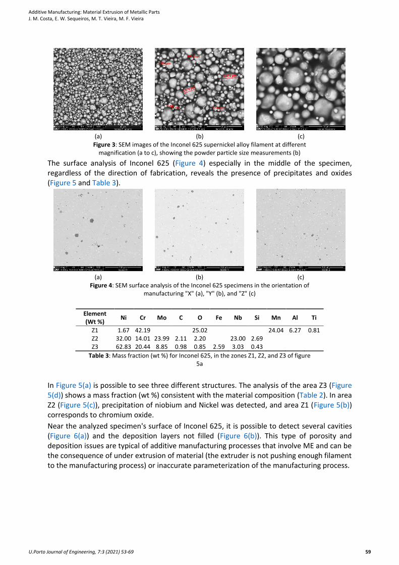
The powder particles available in the Inconel 625 filament are under 10 µm and present the typical shape of spherical particles —additional validations to determine Gaussian particle size distribution and a shape factor, as shown in Figure 3.
Additive Manufacturing: Material Extrusion of Metallic Parts J. M. Costa, E. W. Sequeiros, M. T. Vieira, M. F. Vieira
U.Porto Journal of Engineering, 7:3 (2021) 53-69 59
(a) (b) (c)
Figure 3: SEM images of the Inconel 625 supernickel alloy filament at different magnification (a to c), showing the powder particle size measurements (b)
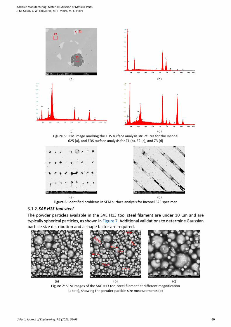
The surface analysis of Inconel 625 (Figure 4) especially in the middle of the specimen, regardless of the direction of fabrication, reveals the presence of precipitates and oxides (Figure 5 and Table 3).
(a) (b) (c)
Figure 4: SEM surface analysis of the Inconel 625 specimens in the orientation of manufacturing "X" (a), "Y" (b), and "Z" (c)
Element (Wt %)
Ni Cr Mo C O Fe Nb Si Mn Al Ti
Z1 1.67 42.19 25.02 24.04 6.27 0.81 Z2 32.00 14.01 23.99 2.11 2.20 23.00 2.69 Z3 62.83 20.44 8.85 0.98 0.85 2.59 3.03 0.43
Table 3: Mass fraction (wt %) for Inconel 625, in the zones Z1, Z2, and Z3 of figure 5a
In Figure 5(a) is possible to see three different structures. The analysis of the area Z3 (Figure 5(d)) shows a mass fraction (wt %) consistent with the material composition (Table 2). In area Z2 (Figure 5(c)), precipitation of niobium and Nickel was detected, and area Z1 (Figure 5(b)) corresponds to chromium oxide.
Near the analyzed specimen's surface of Inconel 625, it is possible to detect several cavities (Figure 6(a)) and the deposition layers not filled (Figure 6(b)). This type of porosity and deposition issues are typical of additive manufacturing processes that involve ME and can be the consequence of under extrusion of material (the extruder is not pushing enough filament to the manufacturing process) or inaccurate parameterization of the manufacturing process.
Additive Manufacturing: Material Extrusion of Metallic Parts J. M. Costa, E. W. Sequeiros, M. T. Vieira, M. F. Vieira
U.Porto Journal of Engineering, 7:3 (2021) 53-69 60
(a) (b)
(c) (d) Figure 5: SEM image marking the EDS surface analysis structures for the Inconel
625 (a), and EDS surface analysis for Z1 (b), Z2 (c), and Z3 (d)
(a) (b)
Figure 6: Identified problems in SEM surface analysis for Inconel 625 specimen
SAE H13 tool steel
The powder particles available in the SAE H13 tool steel filament are under 10 µm and are typically spherical particles, as shown in Figure 7. Additional validations to determine Gaussian particle size distribution and a shape factor are required.
(a) (b) (c)
Figure 7: SEM images of the SAE H13 tool steel filament at different magnification (a to c), showing the powder particle size measurements (b)
Additive Manufacturing: Material Extrusion of Metallic Parts J. M. Costa, E. W. Sequeiros, M. T. Vieira, M. F. Vieira
U.Porto Journal of Engineering, 7:3 (2021) 53-69 61
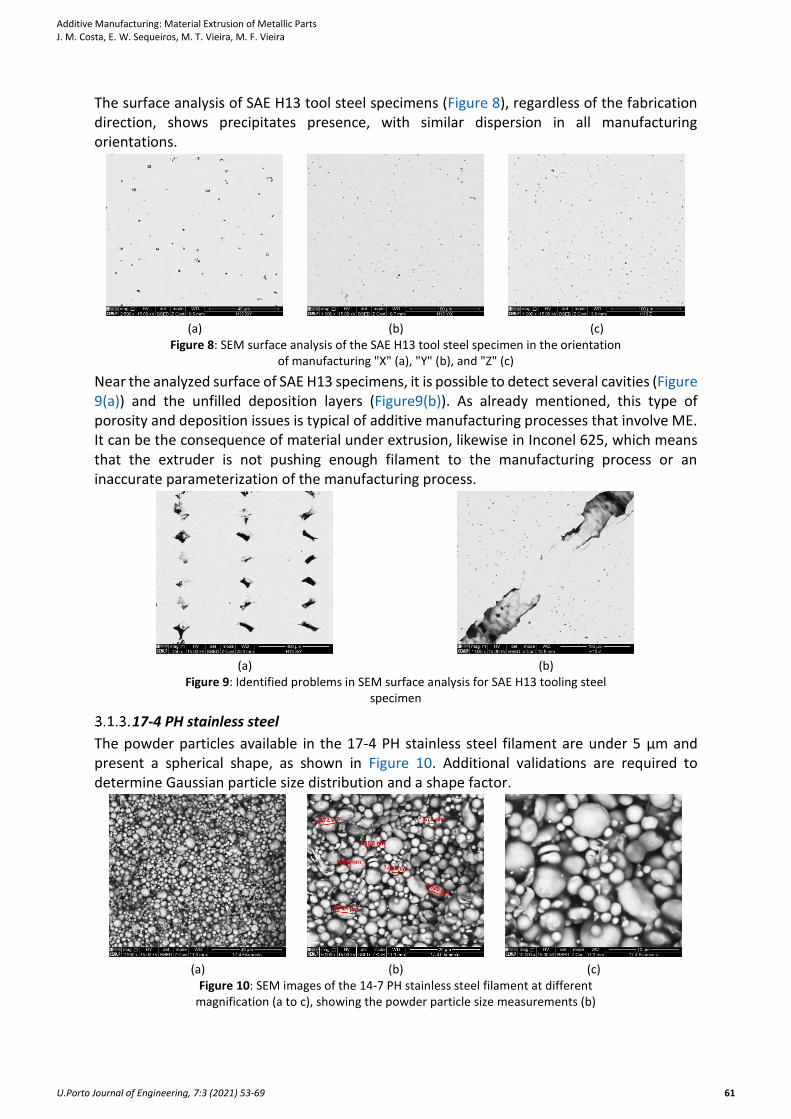
The surface analysis of SAE H13 tool steel specimens (Figure 8), regardless of the fabrication direction, shows precipitates presence, with similar dispersion in all manufacturing orientations.
(a) (b) (c)
Figure 8: SEM surface analysis of the SAE H13 tool steel specimen in the orientation of manufacturing "X" (a), "Y" (b), and "Z" (c)
Near the analyzed surface of SAE H13 specimens, it is possible to detect several cavities (Figure 9(a)) and the unfilled deposition layers (Figure9(b)). As already mentioned, this type of porosity and deposition issues is typical of additive manufacturing processes that involve ME. It can be the consequence of material under extrusion, likewise in Inconel 625, which means that the extruder is not pushing enough filament to the manufacturing process or an inaccurate parameterization of the manufacturing process.
(a) (b)
Figure 9: Identified problems in SEM surface analysis for SAE H13 tooling steel specimen
17-4 PH stainless steel
The powder particles available in the 17-4 PH stainless steel filament are under 5 µm and present a spherical shape, as shown in Figure 10. Additional validations are required to determine Gaussian particle size distribution and a shape factor.
(a) (b) (c)
Figure 10: SEM images of the 14-7 PH stainless steel filament at different magnification (a to c), showing the powder particle size measurements (b)
Additive Manufacturing: Material Extrusion of Metallic Parts J. M. Costa, E. W. Sequeiros, M. T. Vieira, M. F. Vieira
U.Porto Journal of Engineering, 7:3 (2021) 53-69 62
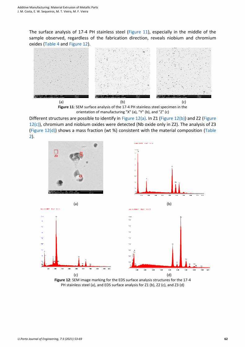
The surface analysis of 17-4 PH stainless steel (Figure 11), especially in the middle of the sample observed, regardless of the fabrication direction, reveals niobium and chromium oxides (Table 4 and Figure 12).
(a) (b) (c)
Figure 11: SEM surface analysis of the 17-4 PH stainless steel specimen in the orientation of manufacturing "X" (a), "Y" (b), and "Z" (c)
Different structures are possible to identify in Figure 12(a). In Z1 (Figure 12(b)) and Z2 (Figure 12(c)), chromium and niobium oxides were detected (Nb oxide only in Z2). The analysis of Z3 (Figure 12(d)) shows a mass fraction (wt %) consistent with the material composition (Table 2).
(a) (b)
(c) (d)
Figure 12: SEM image marking for the EDS surface analysis structures for the 17-4 PH stainless steel (a), and EDS surface analysis for Z1 (b), Z2 (c), and Z3 (d)
Additive Manufacturing: Material Extrusion of Metallic Parts J. M. Costa, E. W. Sequeiros, M. T. Vieira, M. F. Vieira
U.Porto Journal of Engineering, 7:3 (2021) 53-69 63
Element (Wt %)
C Cr Fe Ni Cu O Si Mn Fe Nb
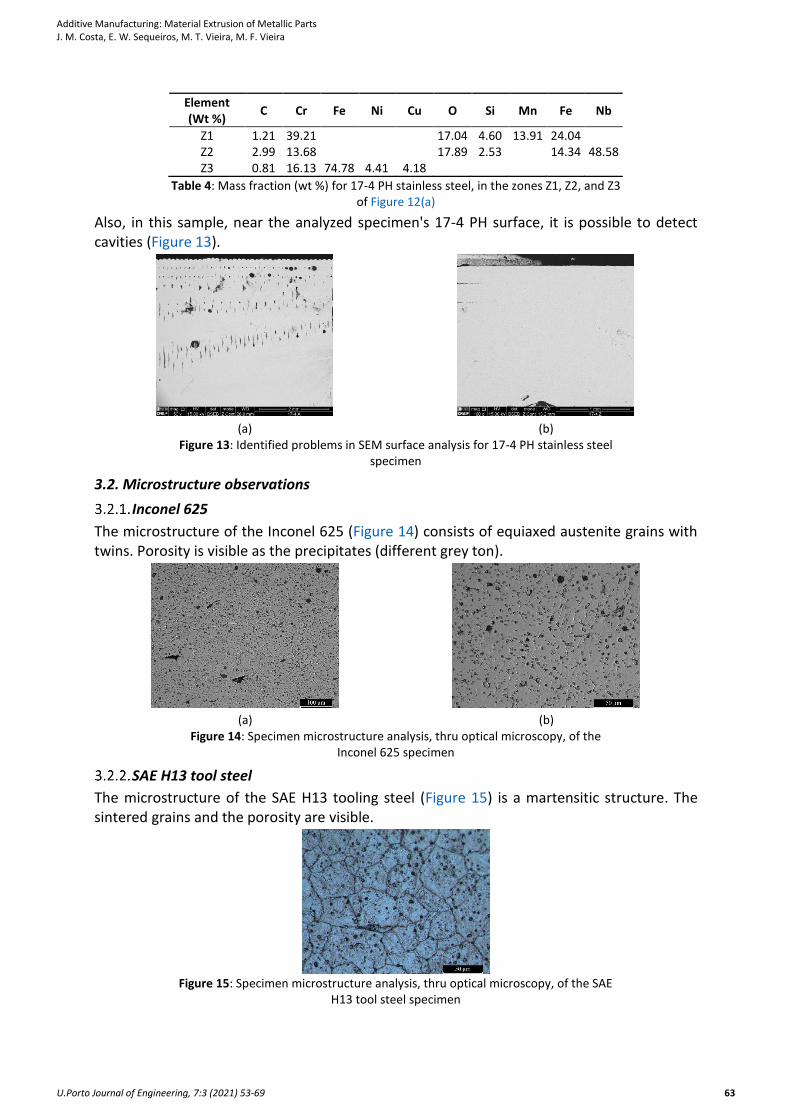
Z1 1.21 39.21 17.04 4.60 13.91 24.04 Z2 2.99 13.68 17.89 2.53 14.34 48.58 Z3 0.81 16.13 74.78 4.41 4.18
Table 4: Mass fraction (wt %) for 17-4 PH stainless steel, in the zones Z1, Z2, and Z3 of Figure 12(a)
Also, in this sample, near the analyzed specimen's 17-4 PH surface, it is possible to detect cavities (Figure 13).
(a) (b)
Figure 13: Identified problems in SEM surface analysis for 17-4 PH stainless steel specimen
3.2. Microstructure observations
Inconel 625
The microstructure of the Inconel 625 (Figure 14) consists of equiaxed austenite grains with twins. Porosity is visible as the precipitates (different grey ton).
(a) (b)
Figure 14: Specimen microstructure analysis, thru optical microscopy, of the Inconel 625 specimen
SAE H13 tool steel
The microstructure of the SAE H13 tooling steel (Figure 15) is a martensitic structure. The sintered grains and the porosity are visible.
Figure 15: Specimen microstructure analysis, thru optical microscopy, of the SAE
H13 tool steel specimen
Additive Manufacturing: Material Extrusion of Metallic Parts J. M. Costa, E. W. Sequeiros, M. T. Vieira, M. F. Vieira
U.Porto Journal of Engineering, 7:3 (2021) 53-69 64
17-4 PH stainless steel
The microstructure of this steel consists of a martensitic structure with precipitates and porosity.
(a) (b)
Figure 16: Specimen microstructure analysis, thru optical microscopy, of the 17 4PH stainless steel specimen
3.3. Mechanical characterizations
Hardness
Hardness values for the as-sintered steel components could not match the reference values provided by the material supplier, presented in Table 5. In SAE H13, the deviation is high, which means variations alongside the sample, possibly due to the deposition process. In the 17-4 PH stainless steel, although 2 HRC bellow reference value, the deviation is smaller, revealing a more homogeneous surface.
Hardness Rockwell C
SAE H13 17-4 PH
Reference Value 40 36 𝒙 ̅ (as-sintered) 37 34
σ 2 1
Table 5: Rockwell C hardness for the steels evaluated
Tensile strength
The tensile strength reference values are presented in Table 6.
Tensile Strength (Reference Value)
Inconel 625 SAE H13 17-4 PH
Rm (MPa) 765 1420 1250 Rp0,2 (MPa) 334 800 1100
Elongation (%) 42 5 6
Table 6: Reference values of tensile strength for the evaluated materials
The results achieved for all the materials evaluated in this work are below reference values, provided by the material supplier, as shown in Table 7. In the SAE H13 tool steel, it was impossible to get results for Rp0,2 and elongation. For the 17-4 PH stainless steel, the elongation value was very high compared to the reference value, and the tensile strength at rupture is below reference values.
Tensile Strength Inconel 625 SAE H13 17-4 PH
Rm (MPa) 726 1306 1113 Rp0,2 (MPa) 334
Problems during test 1075
Elongation (%) 41 28
Table 7: Tensile strength results for the materials evaluated
Three possibilities can justify this. The first justification was noticed during testing, where it was possible to see some sliding from specimen head in the equipment grip; increase the head of the specimen and include some features to decrease slip could be a plus. The second justification could be a poor debinding and sintering process, which might have increased
Additive Manufacturing: Material Extrusion of Metallic Parts J. M. Costa, E. W. Sequeiros, M. T. Vieira, M. F. Vieira
U.Porto Journal of Engineering, 7:3 (2021) 53-69 65
porosity (as seen previously) and consequently affected the mechanical properties. There is a third justification where exists the possibility of both these justifications could be co-occurring. The third possibility is related to the poor adhesion between layers, which will be augmented by the debinding and sintering process. All these possibilities can occur separately or together to justify what happened.
Relative density
The relative density values for Inconel 625 and SAE H13 are according to reference values, and for 17-4 PH it is slightly below, indicated in Table 8.
Relative density Inconel 625 SAE H13 17-4 PH
Reference Value (%) ≥ 96,5 ≥ 94,5 ≥ 96 X
96,5% 95% 94% Y Z
Table 8: Relative density results for the materials evaluated
Although supplier values could be achieved, to check if it is possible to increase components relative density and increase process efficiency, future evaluations for manufacturing (parameters, deposition strategy), debinding, and sintering processes will be considered to decrease components' porosity. Hot isostatic pressure is also an alternative.
Impact test
The specimens were tested with two orthogonal deposition orientations, showing that the orientation does not constrain impact resistance, presented in Table 9.
Impact Test Inconel 625 SAE H13 17-4 PH
Orientation no. 1 23 4 6 Orientation no. 2 25 4 5
Table 9: Impact test results for the materials evaluated
Roughness
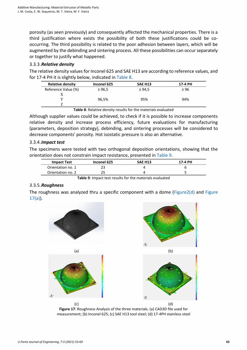
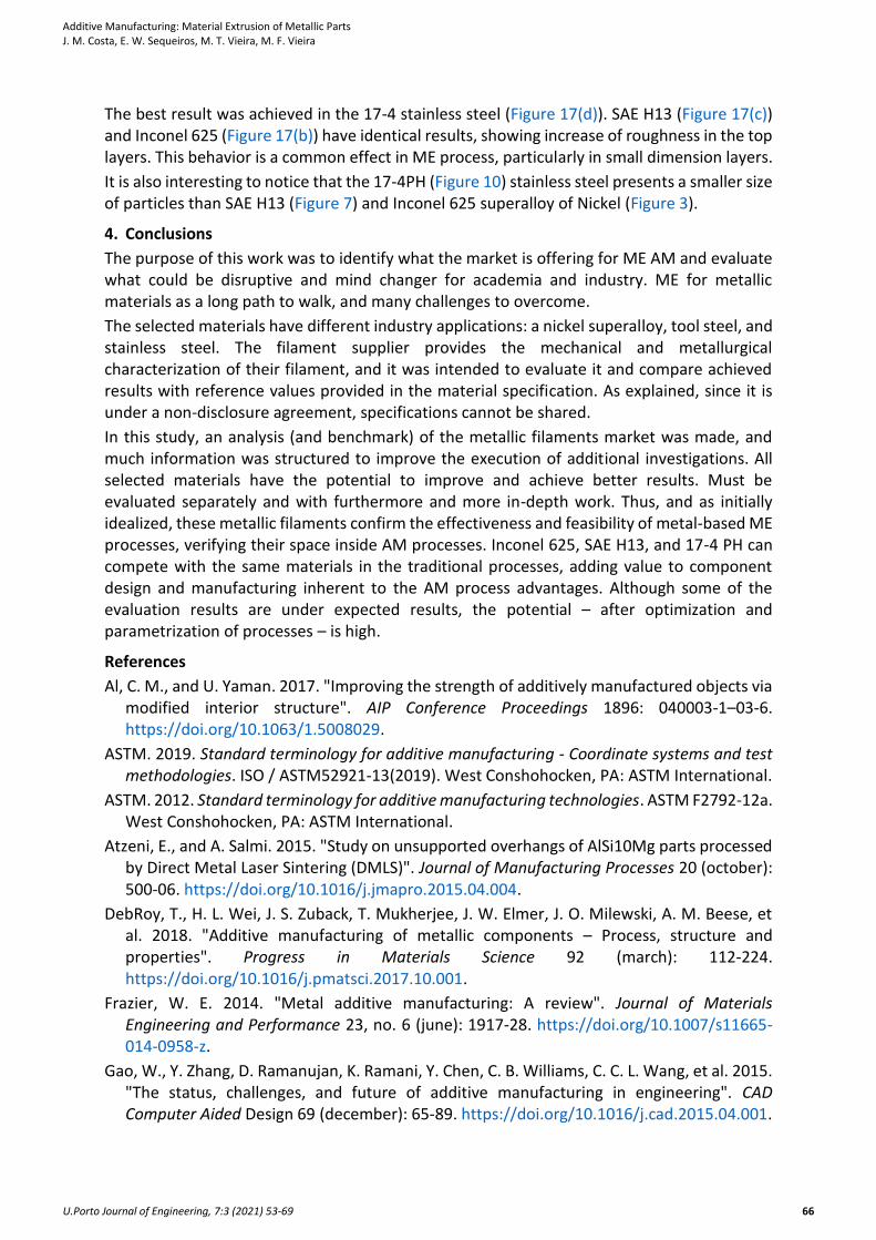
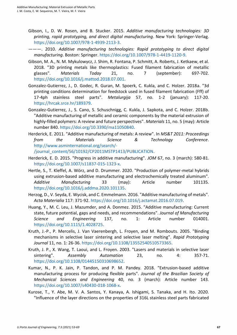
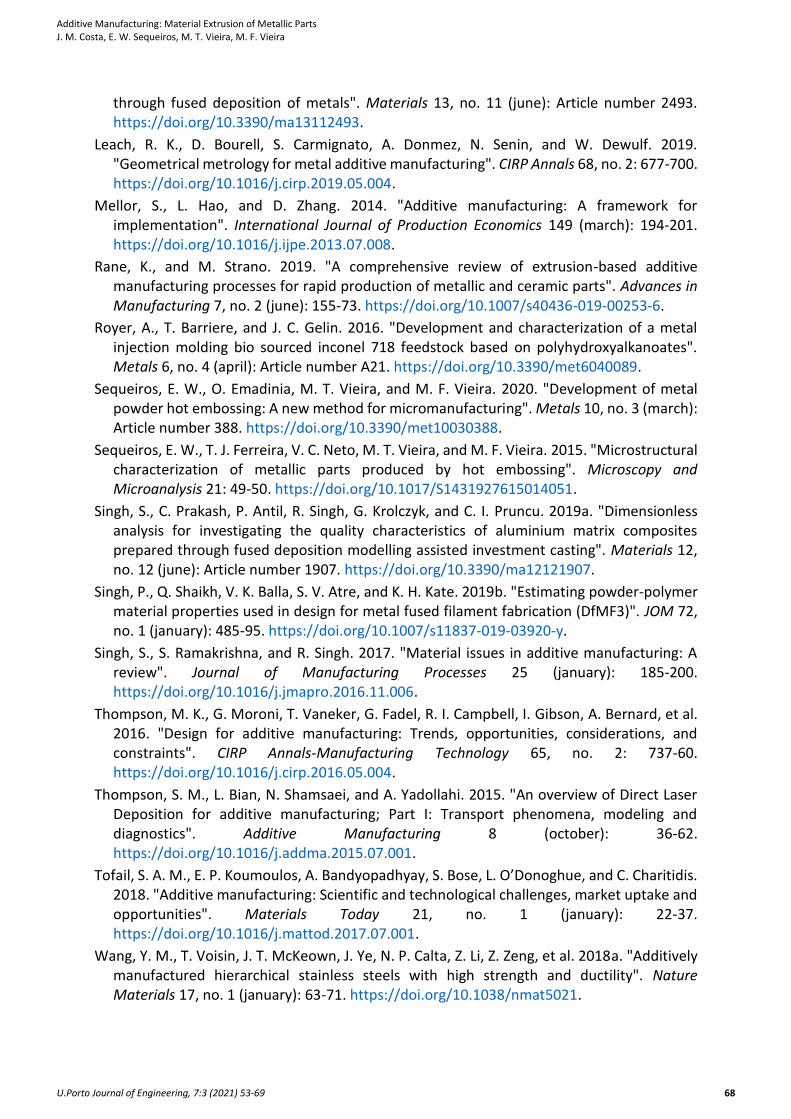
The roughness was analyzed thru a specific component with a dome (Figure2(d) and Figure 17(a)).
(a) (b)
(c) (d)
Figure 17: Roughness Analysis of the three materials. (a) CAD3D file used for measurement; (b) Inconel 625; (c) SAE H13 tool steel; (d) 17-4PH stainless steel
Additive Manufacturing: Material Extrusion of Metallic Parts J. M. Costa, E. W. Sequeiros, M. T. Vieira, M. F. Vieira
U.Porto Journal of Engineering, 7:3 (2021) 53-69 66
The best result was achieved in the 17-4 stainless steel (Figure 17(d)). SAE H13 (Figure 17(c)) and Inconel 625 (Figure 17(b)) have identical results, showing increase of roughness in the top layers. This behavior is a common effect in ME process, particularly in small dimension layers.
It is also interesting to notice that the 17-4PH (Figure 10) stainless steel presents a smaller size of particles than SAE H13 (Figure 7) and Inconel 625 superalloy of Nickel (Figure 3).
4. Conclusions
The purpose of this work was to identify what the market is offering for ME AM and evaluate what could be disruptive and mind changer for academia and industry. ME for metallic materials as a long path to walk, and many challenges to overcome.
The selected materials have different industry applications: a nickel superalloy, tool steel, and stainless steel. The filament supplier provides the mechanical and metallurgical characterization of their filament, and it was intended to evaluate it and compare achieved results with reference values provided in the material specification. As explained, since it is under a non-disclosure agreement, specifications cannot be shared.
In this study, an analysis (and benchmark) of the metallic filaments market was made, and much information was structured to improve the execution of additional investigations. All selected materials have the potential to improve and achieve better results. Must be evaluated separately and with furthermore and more in-depth work. Thus, and as initially idealized, these metallic filaments confirm the effectiveness and feasibility of metal-based ME processes, verifying their space inside AM processes. Inconel 625, SAE H13, and 17-4 PH can compete with the same materials in the traditional processes, adding value to component design and manufacturing inherent to the AM process advantages. Although some of the evaluation results are under expected results, the potential – after optimization and parametrization of processes – is high.
References
Al, C. M., and U. Yaman. 2017. "Improving the strength of additively manufactured objects via modified interior structure". AIP Conference Proceedings 1896: 040003-1–03-6. https://doi.org/10.1063/1.5008029.
ASTM. 2019. Standard terminology for additive manufacturing - Coordinate systems and test methodologies. ISO / ASTM52921-13(2019). West Conshohocken, PA: ASTM International.
ASTM. 2012. Standard terminology for additive manufacturing technologies. ASTM F2792-12a. West Conshohocken, PA: ASTM International.
Atzeni, E., and A. Salmi. 2015. "Study on unsupported overhangs of AlSi10Mg parts processed by Direct Metal Laser Sintering (DMLS)". Journal of Manufacturing Processes 20 (october): 500-06. https://doi.org/10.1016/j.jmapro.2015.04.004.
DebRoy, T., H. L. Wei, J. S. Zuback, T. Mukherjee, J. W. Elmer, J. O. Milewski, A. M. Beese, et al. 2018. "Additive manufacturing of metallic components – Process, structure and properties". Progress in Materials Science 92 (march): 112-224. https://doi.org/10.1016/j.pmatsci.2017.10.001.
Frazier, W. E. 2014. "Metal additive manufacturing: A review". Journal of Materials Engineering and Performance 23, no. 6 (june): 1917-28. https://doi.org/10.1007/s11665-014-0958-z.
Gao, W., Y. Zhang, D. Ramanujan, K. Ramani, Y. Chen, C. B. Williams, C. C. L. Wang, et al. 2015. "The status, challenges, and future of additive manufacturing in engineering". CAD Computer Aided Design 69 (december): 65-89. https://doi.org/10.1016/j.cad.2015.04.001.
Additive Manufacturing: Material Extrusion of Metallic Parts J. M. Costa, E. W. Sequeiros, M. T. Vieira, M. F. Vieira
U.Porto Journal of Engineering, 7:3 (2021) 53-69 67
Gibson, I., D. W. Rosen, and B. Stucker. 2015. Additive manufacturing technologies: 3D printing, rapid prototyping, and direct digital manufacturing. New York: Springer-Verlag. https://doi.org/10.1007/978-1-4939-2113-3.
———. 2010. Additive manufacturing technologies: Rapid prototyping to direct digital manufacturing. Boston: Springer. https://doi.org/10.1007/978-1-4419-1120-9.
Gibson, M. A., N. M. Mykulowycz, J. Shim, R. Fontana, P. Schmitt, A. Roberts, J. Ketkaew, et al. 2018. "3D printing metals like thermoplastics: Fused filament fabrication of metallic glasses". Materials Today 21, no. 7 (september): 697-702. https://doi.org/10.1016/j.mattod.2018.07.001.
Gonzalez-Gutierrez, J., D. Godec, R. Guran, M. Spoerk, C. Kukla, and C. Holzer. 2018a. "3d printing conditions determination for feedstock used in fused filament fabrication (Fff) of 17-4ph stainless steel parts". Metalurgija 57, no. 1-2 (january): 117-20. https://hrcak.srce.hr/189379.
Gonzalez-Gutierrez, J., S. Cano, S. Schuschnigg, C. Kukla, J. Sapkota, and C. Holzer. 2018b. "Additive manufacturing of metallic and ceramic components by the material extrusion of highly-filled polymers: A review and future perspectives". Materials 11, no. 5 (may): Article number 840. https://doi.org/10.3390/ma11050840.
Herderick, E. 2011. "Additive manufacturing of metals: A review". In MS&T 2011: Proceedings from the Materials Science & Technology Conference. http://www.asminternational.org/search/-/journal_content/56/10192/CP2011MSTP1413/PUBLICATION.
Herderick, E. D. 2015. "Progress in additive manufacturing". JOM 67, no. 3 (march): 580-81. https://doi.org/10.1007/s11837-015-1323-x.
Hertle, S., T. Kleffel, A. Wörz, and D. Drummer. 2020. "Production of polymer-metal hybrids using extrusion-based additive manufacturing and electrochemically treated aluminum". Additive Manufacturing 33 (may): Article number 101135. https://doi.org/10.1016/j.addma.2020.101135.
Herzog, D., V. Seyda, E. Wycisk, and C. Emmelmann. 2016. "Additive manufacturing of metals". Acta Materialia 117: 371-92. https://doi.org/10.1016/j.actamat.2016.07.019.
Huang, Y., M. C. Leu, J. Mazumder, and A. Donmez. 2015. "Additive manufacturing: Current state, future potential, gaps and needs, and recommendations". Journal of Manufacturing Science and Engineering 137, no. 1: Article number 014001. https://doi.org/10.1115/1.4028725.
Kruth, J.‐P., P. Mercelis, J. Van Vaerenbergh, L. Froyen, and M. Rombouts. 2005. "Binding mechanisms in selective laser sintering and selective laser melting". Rapid Prototyping Journal 11, no. 1: 26-36. https://doi.org/10.1108/13552540510573365.
Kruth, J. P., X. Wang, T. Laoui, and L. Froyen. 2003. "Lasers and materials in selective laser sintering". Assembly Automation 23, no. 4: 357-71. https://doi.org/10.1108/01445150310698652.
Kumar, N., P. K. Jain, P. Tandon, and P. M. Pandey. 2018. "Extrusion-based additive manufacturing process for producing flexible parts". Journal of the Brazilian Society of Mechanical Sciences and Engineering 40, no. 3 (march): Article number 143. https://doi.org/10.1007/s40430-018-1068-x.
Kurose, T., Y. Abe, M. V. A. Santos, Y. Kanaya, A. Ishigami, S. Tanaka, and H. Ito. 2020. "Influence of the layer directions on the properties of 316L stainless steel parts fabricated
Additive Manufacturing: Material Extrusion of Metallic Parts J. M. Costa, E. W. Sequeiros, M. T. Vieira, M. F. Vieira
U.Porto Journal of Engineering, 7:3 (2021) 53-69 68
through fused deposition of metals". Materials 13, no. 11 (june): Article number 2493. https://doi.org/10.3390/ma13112493.
Leach, R. K., D. Bourell, S. Carmignato, A. Donmez, N. Senin, and W. Dewulf. 2019. "Geometrical metrology for metal additive manufacturing". CIRP Annals 68, no. 2: 677-700. https://doi.org/10.1016/j.cirp.2019.05.004.
Mellor, S., L. Hao, and D. Zhang. 2014. "Additive manufacturing: A framework for implementation". International Journal of Production Economics 149 (march): 194-201. https://doi.org/10.1016/j.ijpe.2013.07.008.
Rane, K., and M. Strano. 2019. "A comprehensive review of extrusion-based additive manufacturing processes for rapid production of metallic and ceramic parts". Advances in Manufacturing 7, no. 2 (june): 155-73. https://doi.org/10.1007/s40436-019-00253-6.
Royer, A., T. Barriere, and J. C. Gelin. 2016. "Development and characterization of a metal injection molding bio sourced inconel 718 feedstock based on polyhydroxyalkanoates". Metals 6, no. 4 (april): Article number A21. https://doi.org/10.3390/met6040089.
Sequeiros, E. W., O. Emadinia, M. T. Vieira, and M. F. Vieira. 2020. "Development of metal powder hot embossing: A new method for micromanufacturing". Metals 10, no. 3 (march): Article number 388. https://doi.org/10.3390/met10030388.
Sequeiros, E. W., T. J. Ferreira, V. C. Neto, M. T. Vieira, and M. F. Vieira. 2015. "Microstructural characterization of metallic parts produced by hot embossing". Microscopy and Microanalysis 21: 49-50. https://doi.org/10.1017/S1431927615014051.
Singh, S., C. Prakash, P. Antil, R. Singh, G. Krolczyk, and C. I. Pruncu. 2019a. "Dimensionless analysis for investigating the quality characteristics of aluminium matrix composites prepared through fused deposition modelling assisted investment casting". Materials 12, no. 12 (june): Article number 1907. https://doi.org/10.3390/ma12121907.
Singh, P., Q. Shaikh, V. K. Balla, S. V. Atre, and K. H. Kate. 2019b. "Estimating powder-polymer material properties used in design for metal fused filament fabrication (DfMF3)". JOM 72, no. 1 (january): 485-95. https://doi.org/10.1007/s11837-019-03920-y.
Singh, S., S. Ramakrishna, and R. Singh. 2017. "Material issues in additive manufacturing: A review". Journal of Manufacturing Processes 25 (january): 185-200. https://doi.org/10.1016/j.jmapro.2016.11.006.
Thompson, M. K., G. Moroni, T. Vaneker, G. Fadel, R. I. Campbell, I. Gibson, A. Bernard, et al. 2016. "Design for additive manufacturing: Trends, opportunities, considerations, and constraints". CIRP Annals-Manufacturing Technology 65, no. 2: 737-60. https://doi.org/10.1016/j.cirp.2016.05.004.
Thompson, S. M., L. Bian, N. Shamsaei, and A. Yadollahi. 2015. "An overview of Direct Laser Deposition for additive manufacturing; Part I: Transport phenomena, modeling and diagnostics". Additive Manufacturing 8 (october): 36-62. https://doi.org/10.1016/j.addma.2015.07.001.
Tofail, S. A. M., E. P. Koumoulos, A. Bandyopadhyay, S. Bose, L. O’Donoghue, and C. Charitidis. 2018. "Additive manufacturing: Scientific and technological challenges, market uptake and opportunities". Materials Today 21, no. 1 (january): 22-37. https://doi.org/10.1016/j.mattod.2017.07.001.
Wang, Y. M., T. Voisin, J. T. McKeown, J. Ye, N. P. Calta, Z. Li, Z. Zeng, et al. 2018a. "Additively manufactured hierarchical stainless steels with high strength and ductility". Nature Materials 17, no. 1 (january): 63-71. https://doi.org/10.1038/nmat5021.
Additive Manufacturing: Material Extrusion of Metallic Parts J. M. Costa, E. W. Sequeiros, M. T. Vieira, M. F. Vieira
U.Porto Journal of Engineering, 7:3 (2021) 53-69 69
Wang, Y., K. Li, P. Li, J. Sun, L. Ye, Y. Dai, A. Tang, et al. 2018b. "Community-based comprehensive measures to prevent severe fever with thrombocytopenia syndrome, China". International Journal of Infectious Diseases 73: 63-66. https://doi.org/10.1016/j.ijid.2018.06.002.
Wu, A. S., D. W. Brown, M. Kumar, G. F. Gallegos, and W. E. King. 2014. "An experimental investigation into additive manufacturing-induced residual stresses in 316L stainless steel". Metallurgical and Materials Transactions A: Physical Metallurgy and Materials Science 45, no. 13 (october): 6260-70. https://doi.org/10.1007/s11661-014-2549-x.
Zeng, K., D. Pal, C. Teng, and B. E. Stucker. 2015. "Evaluations of effective thermal conductivity of support structures in selective laser melting". Additive Manufacturing 6 (april): 67-73. https://doi.org/10.1016/j.addma.2015.03.004.
Acknowledgments
We thank COMPETE 2020, PORTUGAL 2020, and European Union for supporting CARAVELA - Desenvolvimento e Demonstração de building blocks para microlançadores (POCI-01-0247-FEDER-039796). Several of these characterizations were made under the Master of Metallurgical and Materials Engineering, in the Advanced Materials Class of 2019-20, of the University of Porto – Faculty of Engineering (FEUP).


![A Novel Extrusion-Based Additive Manufacturing Process for ...utw10945.utweb.utexas.edu/sites/default/files/2016/121-Ghazanfari.pdfSintering (SLS) [3], Stereolithography (SLA) [4],](https://img.pdfslide.us/doc/110x75/611e9c7a6f3485277f60f918/a-novel-extrusion-based-additive-manufacturing-process-for-sintering-sls-3.jpg)