Embed Size (px)
Citation preview
10 Appendix
Critical success factors and competition strategiesSiegwart and Sieger [Siegwart, 91] presented a model that allowed a structured evaluation of new technologies. For this they established so-called critical success factors. These are points that can be condensed into individual factors and there-fore are used as a measure for evaluating the success of a process in the context of a corporate strategy.
Although the quantification of success factors is currently controversial, they still are an effective instrument to discuss and evaluate products and product strate-gies.
Requirements for new products are characterized by the following critical success factors:
� Shortening time of development � Reduction of costs � Increasing the flexibility (product and manufacturing flexibility) � Improving the quality
In general, this list is not obligatory, but currently it suggests a wide consensus.
Single critical success factors are in the mathematical sense not independent of each other, but rather they represent factors that, by weighting and connecting in the sense of a strategy, lead to useful statements. In a strategy, the self-concept of a company in an interplay with its competitors is expressed. Today (it might be dif-ferent tomorrow) successful companies (market leaders and “hidden champions”) pursue the following strategies:
1. Technology leadership (pioneer leadership)2. Cost leadership3. Differentiation4. Concentration5. Overhauling strategy
494 10 Appendix
The critical success factors of time and flexibility are in the foreground of the pio-neer strategy, while quality and costs are in the background. In pursuing cost lead-ership, the rest of the critical success factors step behind the costs. The strategy of differentiation follows for a unique product, for example with an unmistakable de-sign. Compared to quality and flexibility, costs and time play a subordinated role. Concentration is not an independent strategy, but rather is an application of cost leadership and differentiation to a chosen market segment. Outpacing is the change between the strategies of cost leadership and differentiation, based on the situation of the competition. The “provocative outpacing” strategy first involves procuring a share of the market with inexpensive products, followed by differentiation with high-quality products. “Preventive outpacing” goes directly after cost leadership, to fend off low prices from competitors from the beginning.
A strategy known as market skimming is similar to outpacing. A product, prefera-bly upscale, unrivaled, and introduced to the market before the competition, which is temporary and intense, is put on the market with the necessary advertising ex-pense. When the competition begins on the market, the business is over or reduced to a low and low-priced afterbusiness. This applies especially to fancy goods, for example the mp3 player iPod (Apple). In this case, all competitive factors play a similar role, but have different weighting related to the stage.
These examinations show that most of the actually used strategies are a mixture of single projections, which are followed over the period with different weightings.
The individualization of mass products can be seen as a combination of the pioneer and differentiation strategies.
The implementation of the theory explained in the following makes it clear that time especially plays an important role.
Economic model by Siegwart and SingerThe approach of Siegwart and Singer allows for a quantitative assessment of the economic impact in the use of new technologies, taking into account the risk asso-ciated with new technologies. Steger and Conrad [Steger, 95] applied this approach to rapid prototyping. Conventional five-axis milling and stereolithography were compared, for example.
Even from an operational perspective, the authors determine the benefits of stereo-lithography in terms of production time and costs. The quality of the component, in particular on the surfaces, from milling is better.
The strategic assessment of the technology covers all critical success factors in the calculation. The assessment is no longer based on the costs, as in the opera-tional view.
49510 Appendix
ProcedureAn economic efficiency ratio is defined, indicating how well a strategy is supported by the application of rapid prototyping.
The economic efficiency ratio is the quotient of the growth of capacity (capacity value) and the total costs (cost value). The costs include all of the classic cost types and the cost savings that are due to the use of additive manufacturing processes. The capacity includes the critical success factors (which may be defined differently in other basic approaches) cost, quality, and flexibility. The improvement or deteri-oration (in percent) is calculated in each case compared with the conventional ref-erence case (which equals 100 %).
As part of the strategic review, Steger and Conrad compare the economic impor-tance of the use of rapid prototyping for four different competitive strategies:
1. Technology leadership (pioneer strategy)2. Cost leadership3. a) Differentiation or b) Concentration4. Overtaking strategy (outpacing)
Rapid prototyping technology has an influence on the critical success factors of
1. shorter development time,2. reduction of costs,3. improved quality, and4. increased flexibility
entered into the calculation. For this purpose, the effect of an additive manufactur-ing process is estimated on the critical success factors: for each strategy, the criti-cal success factors of time, quality, and flexibility are connected to a capacity value and transferred to the factor cost in a cost value.
The capacity and cost factors consist of a value for the performance ratio, which indicates how much the property in question could be improved by the use of an additive manufacturing process (for example, speed increased by 80% leads to the fulfillment level 180) and a weighting factor (depending on the importance of the criterion for the strategy, between 1 and 3).
The average of the capacity values of time, quality, and flexibility is multiplied by the reciprocal value of the cost value, the efficiency index WI, which is a measure of the potential or prediction of a new technology.
An evaluation of the individual capacity values, with a probability of arriving at the predictions, leads to an economy measure WII and additionally encompasses the risk that is associated with the introduction of the new technology.
The analogous application of the process to the basic technology gives reference values for the assessment of the new technology.
496 10 Appendix
Determine the numerical valuesThe values for the variation of the critical success factors
1. shorter development time,2. reduced costs,3. improved quality, and4. increased flexibility
were estimated as follows:
No. 1: Shortening the development timeQuickly available prototypes have the potential to reduce the development time by up to 80 %.
The shortening of the production time of prototypes often plays only a minor role. This advantage can be used, depending on the strategy, for
� earlier market entry, � quality improvement, or � cost reduction.
The total reduction of development time that is finally realized is therefore depend-ent on the type of strategy.
No. 2: Reducing costThe reduction of costs is achieved in two ways, first, the effect of earlier cost-cutting, and second, through cheaper production of models. The literature states that about 50 % is production costs and that the savings from an earlier assessment of the cost of product development indicate about 25 % of the savings in the production model. Through following necessary processes when using the additive manufacturing pro-cess, with the conventional process the total numbers may still change.
While the cost advantage in the production always occurs, the degree of realization of the further potential, in turn, depends on the strategy.
Reducing costs, therefore, makes up at least 50 % but not more than 75 %.
No. 3: Improving qualityThrough the use of an additive manufacturing process, a higher product maturity is attained earlier.
Methods of QFD (quality function deployment) and FMEA (failure mode and effects analysis) are thereby effectively supported, and an expensive troubleshooting later on is avoided.
The magnitude of the effect depends, as already mentioned, on a cost/benefit strat-egy that determines how much is spent by the time that is saved.
49710 Appendix
No. 4: Increasing flexibilityThe rapid availability of prototypes influences the flexibility outward and inward. Changing market requirements can be quickly and effectively responded to by se-rial identical prototypes.
Shorter reaction times within the company improve communication and put the organization in a position to respond faster and better to changes of all kinds (pro-visions computing process, process production, environmental conditions). They are the basis for continuous learning in an operation and an important factor in increasing the rate of innovation of the company.
A quantification of these effects is very difficult.
In order to obtain meaningful answers, a competitive strategy must be defined, such as cost leadership, and depending on each critical success factor, a perfor-mance level shall be determined. In view of the fact that the maximum savings are 75 % of the cost for the application of rapid prototyping, a performance level of 175 % results (100 % corresponds to conventional milling). Because the cost leader-ship strategy assumes that the time gained is fully reinvested in cost reduction, the success factors of development and quality remain unchanged (100 %), which, how-ever, are difficult to measure. Increased flexibility is assumed to be 20 % (= 120 %).
The performance levels thus determined are weighted by factors of 1 to 3 (1 = low importance, 2 = average meaning, 3 = very important) and hence are the impor-tance of the individual factors of success for each competition strategy.
In the case of cost leadership, this results in a 3 for the cost, a 2 for the time, and a 1 each for quality and for flexibility.
The average of the values of capacity is determined from the product of the weight and degree of completion, and the cost value is the reciprocal of the product of the weight and the degree of satisfaction regarding the success factor costs.
The value of the cost-effectiveness ratio WI results from the ratio of capacity value and cost value. Although it contains estimates for the potential of the technology, it does not consider the risk. Therefore, for each success factor is defined a probabil-ity (<1), multiplied by the value for each success factor and the mean re-formed for the performance. By dividing by the cost value, the profitability index WII follows in terms of risk.
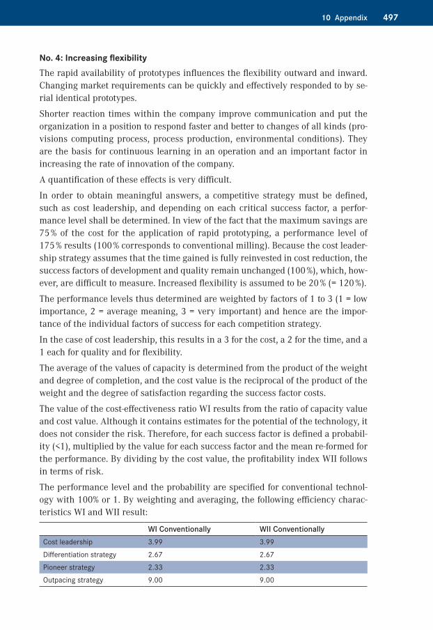
The performance level and the probability are specified for conventional technol-ogy with 100% or 1. By weighting and averaging, the following efficiency charac-teristics WI and WII result:
WI Conventionally WII ConventionallyCost leadership 3.99 3.99Differentiation strategy 2.67 2.67Pioneer strategy 2.33 2.33Outpacing strategy 9.00 9.00
498 10 Appendix
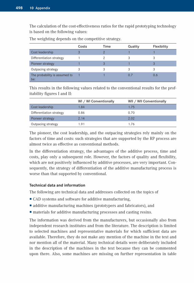
The calculation of the cost-effectiveness ratios for the rapid prototyping technology is based on the following values:
The weighting depends on the competitive strategy.
Costs Time Quality FlexibilityCost leadership 3 2 1 1Differentiation strategy 1 2 3 3Pioneer strategy 1 3 1 3Outpacing strategy 3 3 3 3The probability is assumed to be:
1 1 0.7 0.6
This results in the following values related to the conventional results for the prof-itability figures I and II:
WI / WI Conventionally WII / WII ConventionallyCost leadership 1.84 1.75Differentiation strategy 0.86 0.70Pioneer strategy 2.14 2.02Outpacing strategy 1.91 1.76
The pioneer, the cost leadership, and the outpacing strategies rely mainly on the factors of time and costs: such strategies that are supported by the RP process are almost twice as effective as conventional methods.
In the differentiation strategy, the advantages of the additive process, time and costs, play only a subsequent role. However, the factors of quality and flexibility, which are not positively influenced by additive processes, are very important. Con-sequently, the strategy of differentiation of the additive manufacturing process is worse than that supported by conventional.
Technical data and informationThe following are technical data and addresses collected on the topics of
� CAD systems and software for additive manufacturing, � additive manufacturing machines (prototypers and fabricators), and � materials for additive manufacturing processes and casting resins.
The information was derived from the manufacturers, but occasionally also from independent research institutes and from the literature. The description is limited to selected machines and representative materials for which sufficient data are available. Therefore, they do not make any mention of the machine in the text and nor mention all of the material. Many technical details were deliberately included in the description of the machines in the text because they can be commented upon there. Also, some machines are missing on further representation in table
49910 Appendix
form. If technical information is missing in the table in the appendix, reference should be made to the corresponding chapters. All prices are included in Figs. 8.1 and 8.2, “System Costs.”
The information has been compiled to the best of the author’s knowledge and be-lief. Because of the high speed of development, before using this information, it should be checked on the manufacturers’ website or question the manufacturer. Therefore, wherever Internet addresses were available, they are also indicated. The data from older machines and material can be looked up in previous editions of this book.
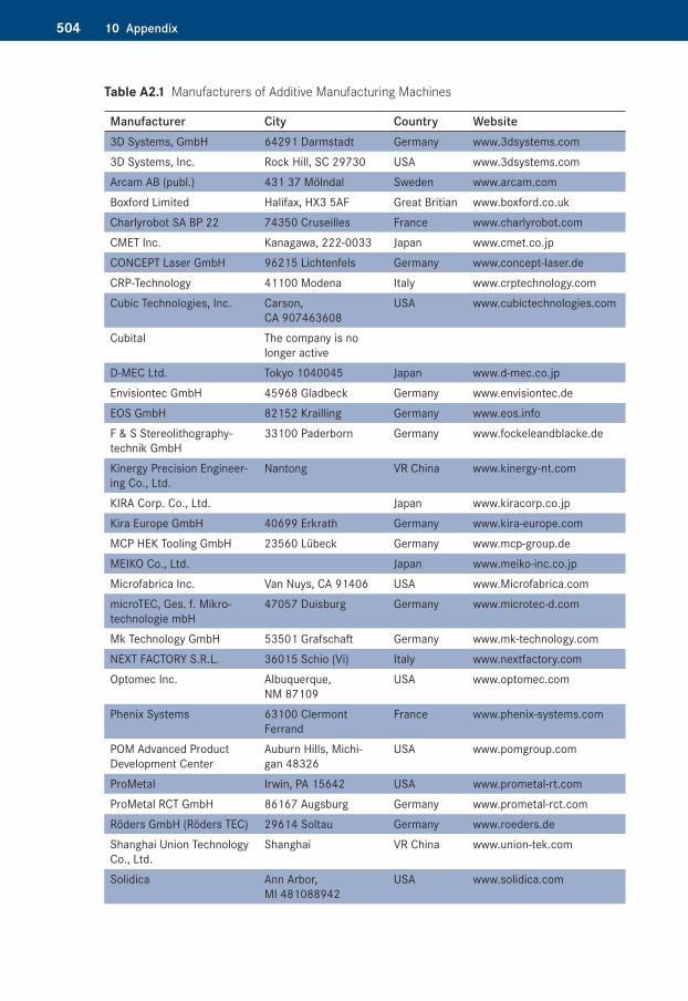
Table A2.1, “Manufacturers of Additive Manufacturing Machines,” also shows manufacturers that are not mentioned in Chapter 3. More information should be obtained directly from the manufacturer. Above all, the current partners are to be reviewed because the distribution networks are continuously expanded. Casting resins are collected in Table A3.12, “Casting Resins.” Because the range here is confusingly large, one elastic, one hard, one impact resistant, one high-tempera-ture resistant, and one clear quality resin were selected as examples. This choice does not mean that similar qualities would not be delivered by other manufactur-ers. In particular, no rating is associated with the selection.
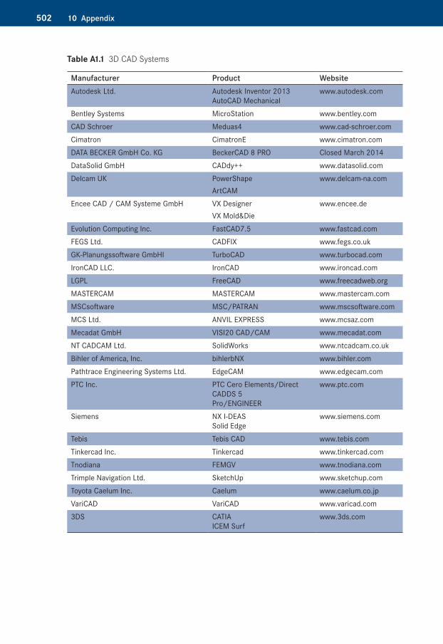
CAD Systems and Software for Additive ManufacturingTable A1.1: 3D CAD Systems
It may be assumed that each of these systems has a STL-capable interface.
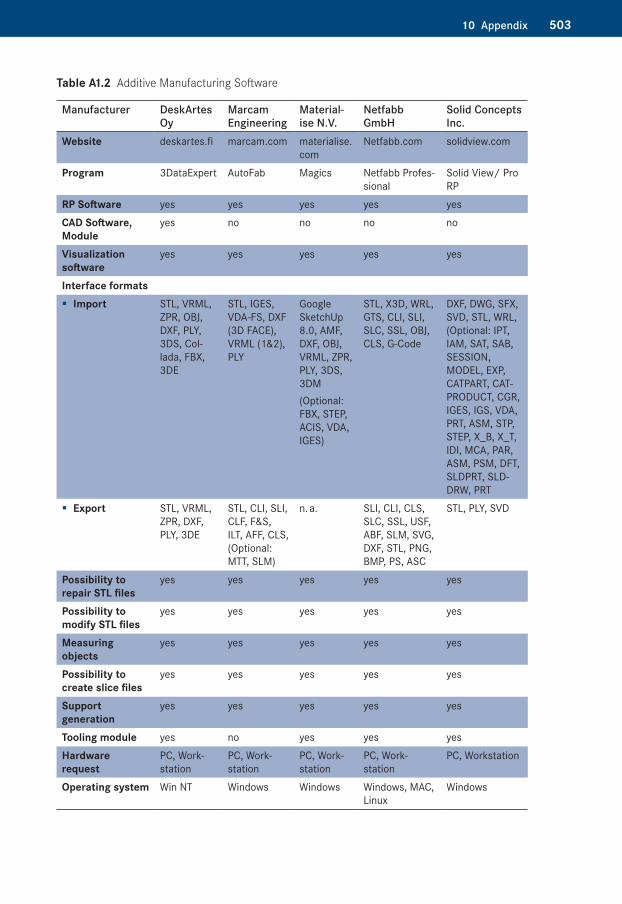
Table A1.2: Additive Manufacturing Software (Rapid Prototyping Software)
Additive Manufacturing Machine (Prototypers and Fabricators)Table A2.1: Manufacturers of Additive Manufacturing Machines
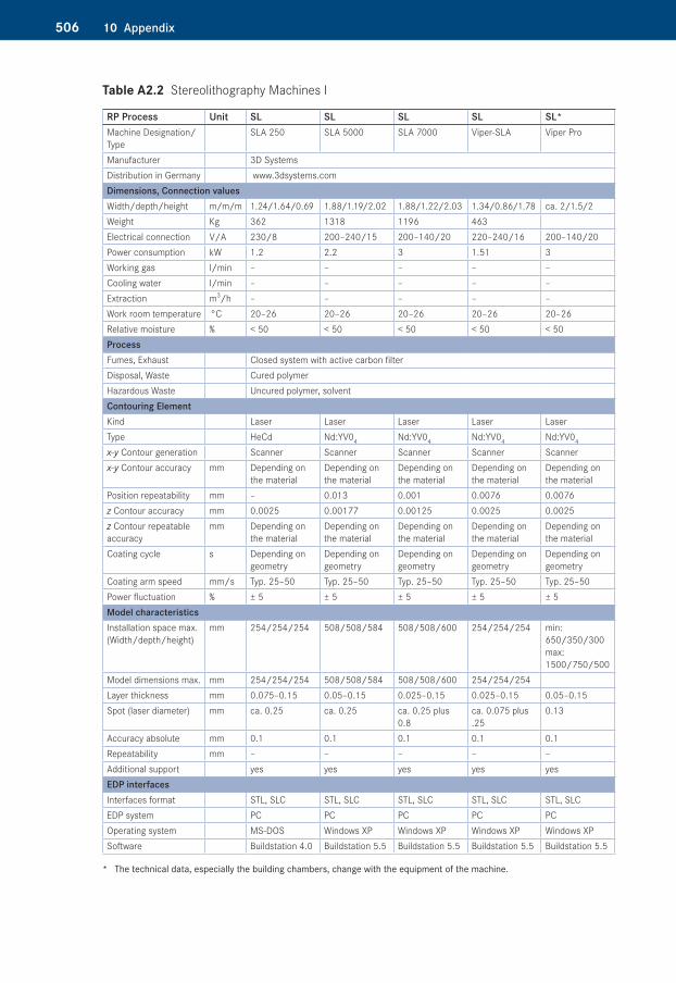
Table A2.2: Stereolithography Machines I
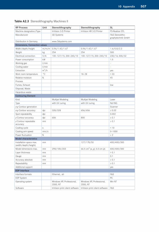
Table A2.3: Stereolithography Machines II
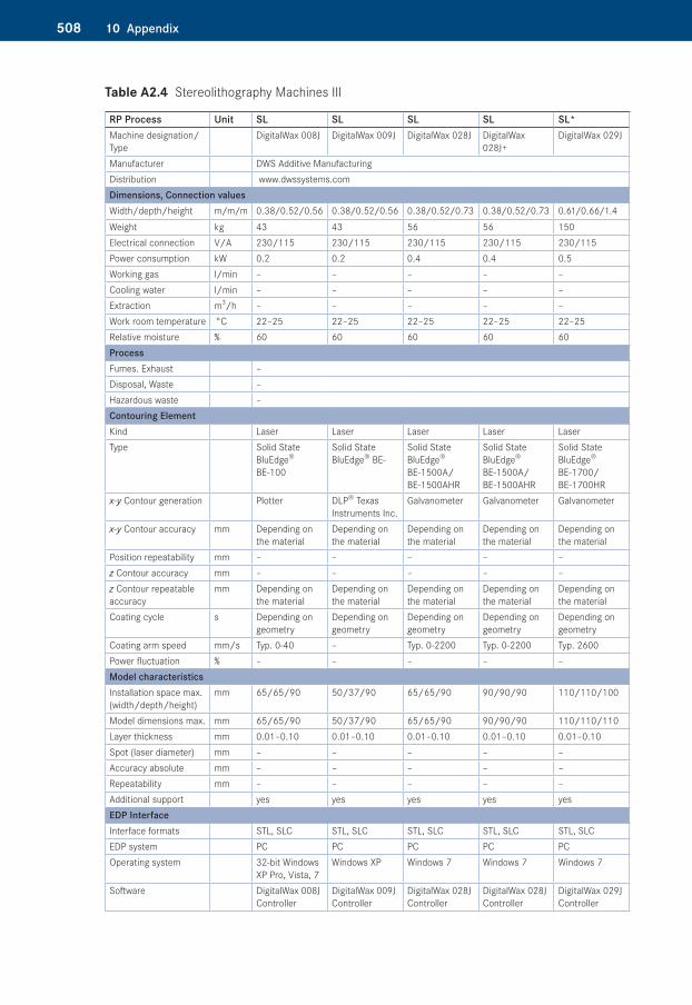
Table A2.4: Stereolithography Machines III
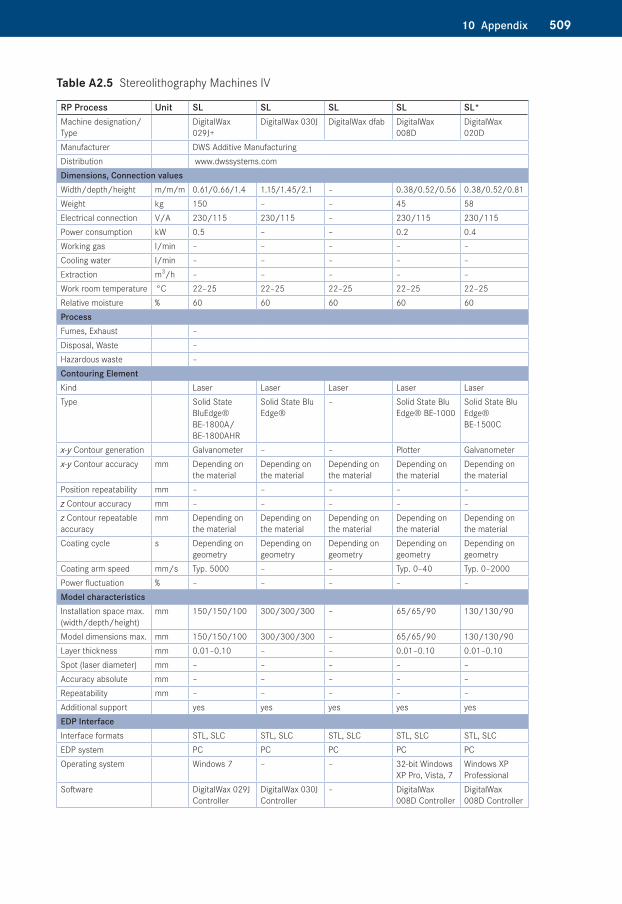
Table A2.5: Stereolithography Machines IV
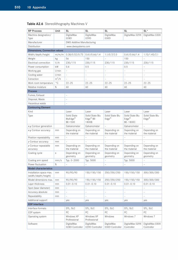
Table A2.6: Stereolithography Machines V
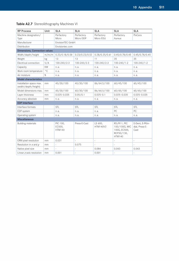
Table A2.7: Stereolithography Machines VI
Table A2.8: Stereolithography Machines VII
Table A2.9: Stereolithography Machines VIII
Table A2.10: Stereolithography Machines IX
Table A2.11: Stereolithography Machines X
Table A2.12: Stereolithography Machines XI
500 10 Appendix
Table A2.13: Stereolithography Machines XII
Table A2.14: Stereolithography Machines XIII
Table A2.15: Stereolithography Machines XIV
Table A2.16: Polymer Printing Machines I
Table A2.17: Polymer Printing Machines II
Table A2.18: Polymer Printing Machines III
Table A2.19: Polymer Printing Machines IV
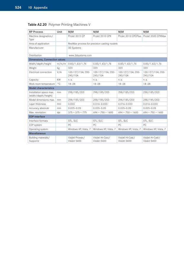
Table A2.20: Polymer Printing Machines V
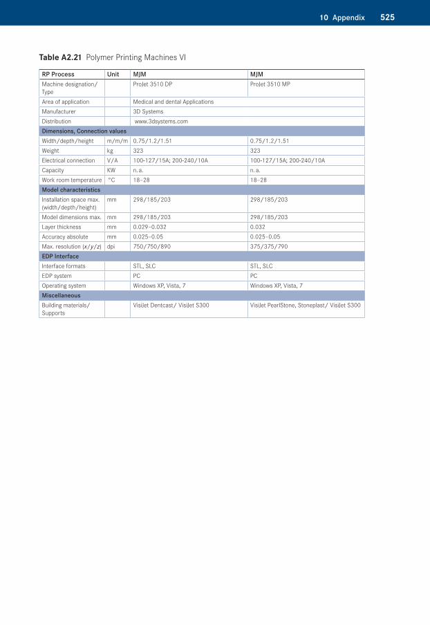
Table A2.21: Polymer Printing Machines VI
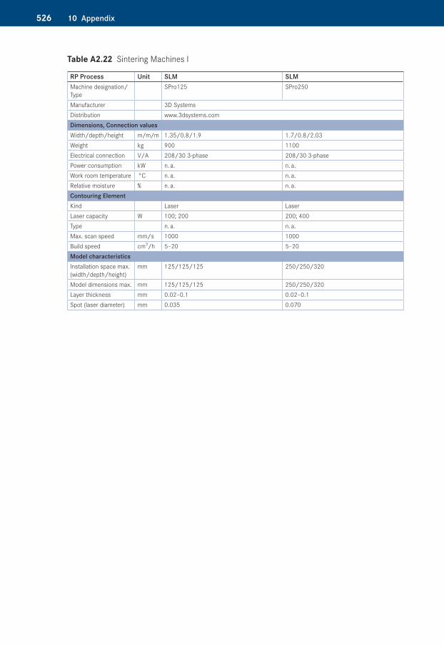
Table A2.22: Sintering Machines I
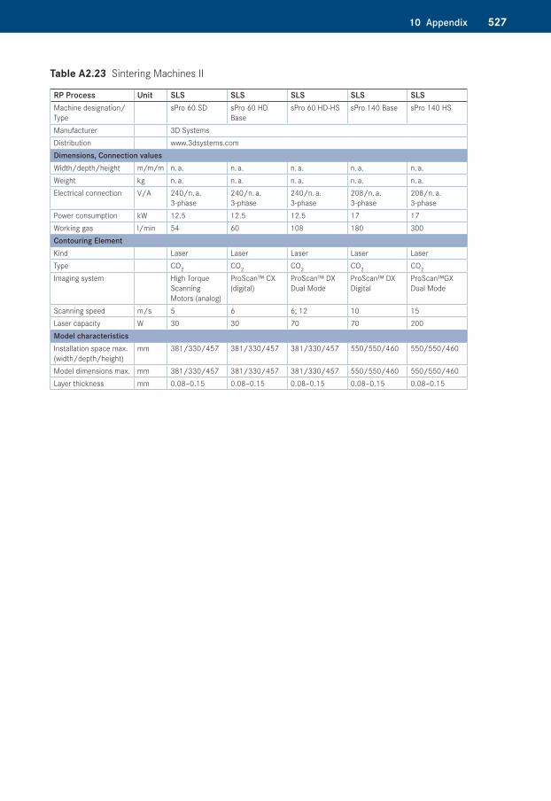
Table A2.23: Sintering Machines II
Table A2.24: Sintering Machines III
Table A2.25: Sintering Machines IV
Table A2.26: Sintering and Melting Machines V
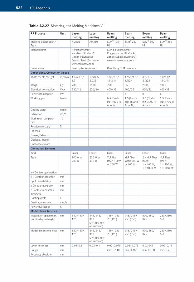
Table A2.27: Sintering and Melting Machines VI
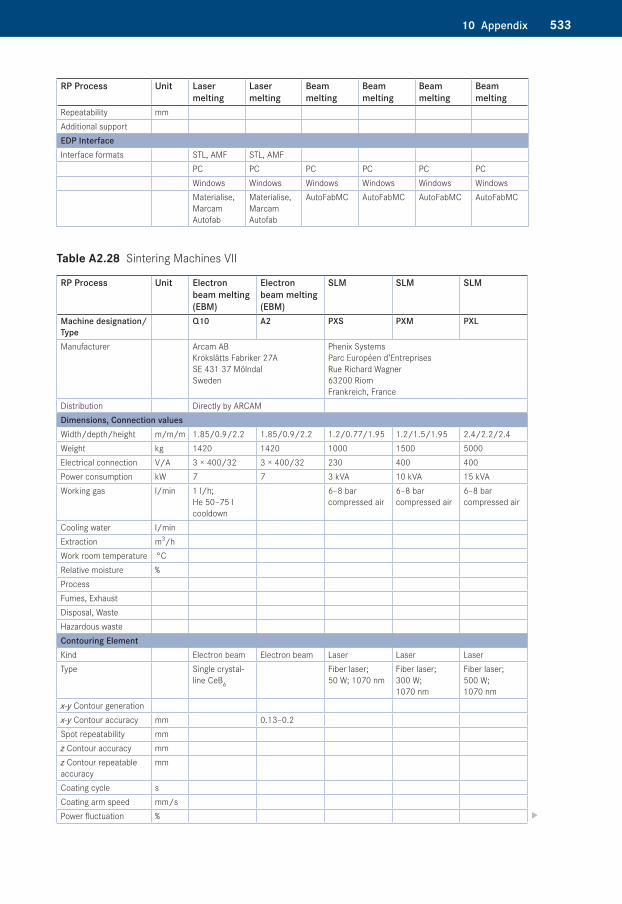
Table A2.28: Sintering Machines VII
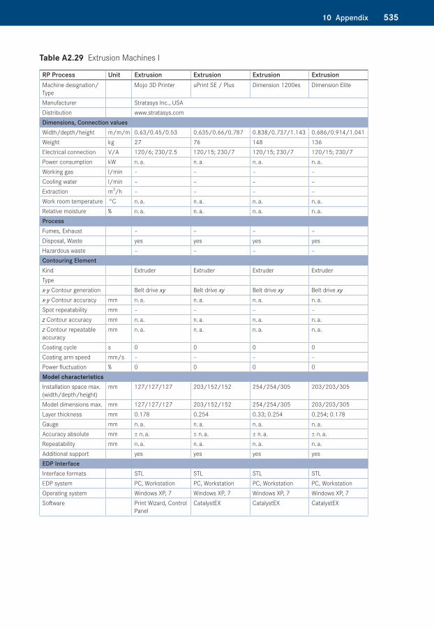
Table A2.29: Extrusion Machines I
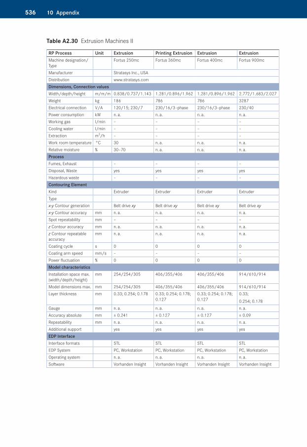
Table A2.30: Extrusion Machines II
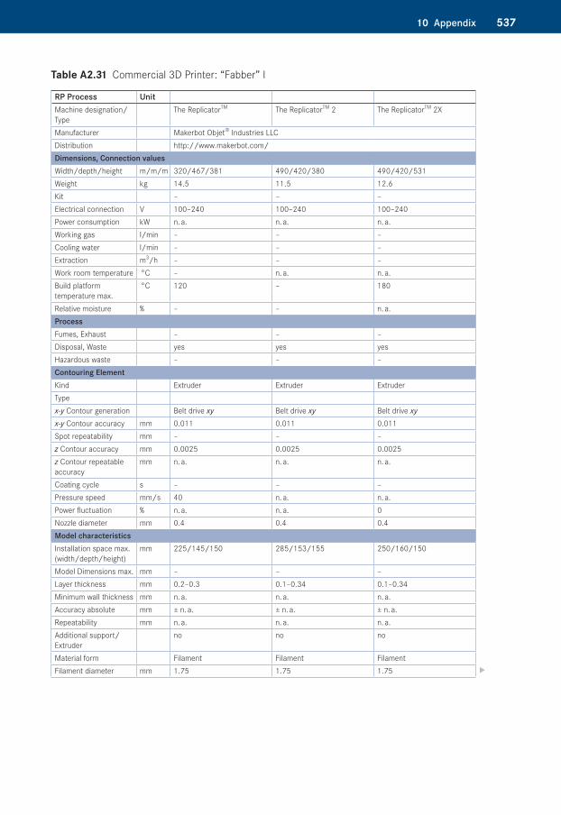
Table A2.31: Commercial 3D Printer: “Fabber” I
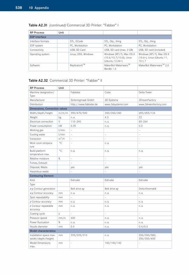
Table A2.32: Commercial 3D Printer: “Fabber” II
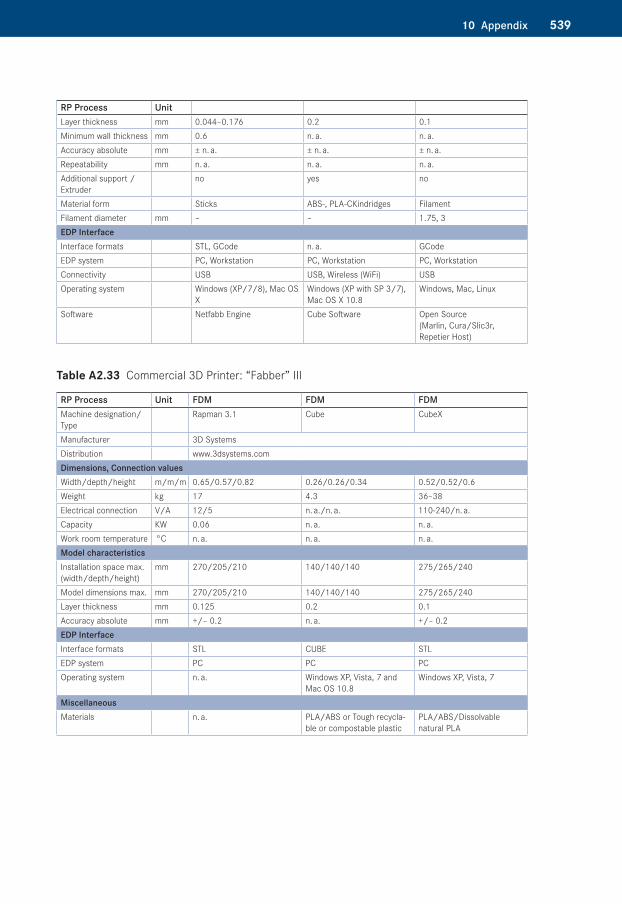
Table A2.33: Commercial 3D Printer: “Fabber” III
Table A2.34: Layer Laminate Machines I
Table A2.35: Layer Laminate Machines II
Table A2.36: Layer Laminate Machines III
Table A2.37: 3D Printer I
Table A2.38: 3D Printer II
Table A2.39: 3D Printer III
Table A2.40: 3D Printer IV
Table A2.41: 3D Printer V
Materials for Additive Manufacturing Processes and Casting ResinsTable A3.1: Stereolithography Materials I
Table A3.2: Stereolithography Materials II
Table A3.3: Stereolithography Materials III
50110 Appendix
Table A3.4: Stereolithography Materials IV
Table A3.5: Stereolithography Materials V
Table A3.6: Stereolithography Materials VI
Table A3.7: Stereolithography Materials VII
Table A3.8: Stereolithography Materials VIII
Table A3.9: Stereolithography Materials IX
Table A3.10: Stereolithography Materials X
Table A3.11: Sintering Materials I
Table A3.12: Sintering Materials II
Table A3.13: Sintering Materials III
Table A3.14: Sintering Materials IV
Table A3.15: Sintering Materials V
Table A3.16: FDM Materials
Table A3.17: Model Maker Materials
Table A3.18: LOM Materials
Table A3.19: 3D Printer Materials
Table A3.20: Casting Resins
502 10 Appendix
Table A1.1 3D CAD Systems
Manufacturer Product WebsiteAutodesk Ltd. Autodesk Inventor 2013
AutoCAD Mechanicalwww.autodesk.com
Bentley Systems MicroStation www.bentley.comCAD Schroer Meduas4 www.cad-schroer.comCimatron CimatronE www.cimatron.comDATA BECKER GmbH Co. KG BeckerCAD 8 PRO Closed March 2014DataSolid GmbH CADdy++ www.datasolid.comDelcam UK PowerShape
ArtCAMwww.delcam-na.com
Encee CAD / CAM Systeme GmbH VX DesignerVX Mold&Die
www.encee.de
Evolution Computing Inc. FastCAD7.5 www.fastcad.comFEGS Ltd. CADFIX www.fegs.co.ukGK-Planungssoftware GmbHI TurboCAD www.turbocad.com IronCAD LLC. IronCAD www.ironcad.com LGPL FreeCAD www.freecadweb.orgMASTERCAM MASTERCAM www.mastercam.comMSCsoftware MSC/PATRAN www.mscsoftware.comMCS Ltd. ANVIL EXPRESS www.mcsaz.comMecadat GmbH VISI20 CAD/CAM www.mecadat.comNT CADCAM Ltd. SolidWorks www.ntcadcam.co.ukBihler of America, Inc. bihlerbNX www.bihler.comPathtrace Engineering Systems Ltd. EdgeCAM www.edgecam.comPTC Inc. PTC Cero Elements/Direct
CADDS 5 Pro/ENGINEER
www.ptc.com
Siemens NX I-DEAS Solid Edge
www.siemens.com
Tebis Tebis CAD www.tebis.comTinkercad Inc. Tinkercad www.tinkercad.comTnodiana FEMGV www.tnodiana.com Trimple Navigation Ltd. SketchUp www.sketchup.comToyota Caelum Inc. Caelum www.caelum.co.jpVariCAD VariCAD www.varicad.com3DS CATIA
ICEM Surfwww.3ds.com
50310 Appendix
Table A1.2�Additive Manufacturing Software
Manufacturer DeskArtes Oy
Marcam Engineering
Materialise N.V.
Netfabb GmbH
Solid Concepts Inc.
Website deskartes.fi marcam.com materialise.com
Netfabb.com solidview.com
Program 3DataExpert AutoFab Magics Netfabb Profes-sional
Solid View/ Pro RP
RP Software yes yes yes yes yesCAD Software, Module
yes no no no no
Visualization software
yes yes yes yes yes
Interface formats � Import STL, VRML,
ZPR, OBJ, DXF, PLY, 3DS, Col-lada, FBX, 3DE
STL, IGES, VDA-FS, DXF (3D FACE), VRML (1&2), PLY
Google SketchUp 8.0, AMF, DXF, OBJ, VRML, ZPR, PLY, 3DS, 3DM(Optional: FBX, STEP, ACIS, VDA, IGES)
STL, X3D, WRL, GTS, CLI, SLI, SLC, SSL, OBJ, CLS, G-Code
DXF, DWG, SFX, SVD, STL, WRL, (Optional: IPT, IAM, SAT, SAB, SESSION, MODEL, EXP, CATPART, CAT-PRODUCT, CGR, IGES, IGS, VDA, PRT, ASM, STP, STEP, X_B, X_T, IDI, MCA, PAR, ASM, PSM, DFT, SLDPRT, SLD-DRW, PRT
� Export STL, VRML, ZPR, DXF, PLY, 3DE
STL, CLI, SLI, CLF, F&S, ILT, AFF, CLS, (Optional: MTT, SLM)
n. a. SLI, CLI, CLS, SLC, SSL, USF, ABF, SLM, SVG, DXF, STL, PNG, BMP, PS, ASC
STL, PLY, SVD
Possibility to repair STL files
yes yes yes yes yes
Possibility to modify STL files
yes yes yes yes yes
Measuring objects
yes yes yes yes yes
Possibility to create slice files
yes yes yes yes yes
Support generation
yes yes yes yes yes
Tooling module yes no yes yes yesHardware request
PC, Work-station
PC, Work-station
PC, Work-station
PC, Work-station
PC, Workstation
Operating system Win NT Windows Windows Windows, MAC, Linux
Windows
504 10 Appendix
Table A2.1�Manufacturers of Additive Manufacturing Machines
Manufacturer City Country Website3D Systems, GmbH 64291 Darmstadt Germany www.3dsystems.com3D Systems, Inc. Rock Hill, SC 29730 USA www.3dsystems.comArcam AB (publ.) 431 37 Mölndal Sweden www.arcam.comBoxford Limited Halifax, HX3 5AF Great Britian www.boxford.co.ukCharlyrobot SA BP 22 74350 Cruseilles France www.charlyrobot.comCMET Inc. Kanagawa, 222-0033 Japan www.cmet.co.jpCONCEPT Laser GmbH 96215 Lichtenfels Germany www.concept-laser.deCRP-Technology 41100 Modena Italy www.crptechnology.comCubic Technologies, Inc. Carson,
CA 907463608USA www.cubictechnologies.com
Cubital The company is no longer active
D-MEC Ltd. Tokyo 1040045 Japan www.d-mec.co.jpEnvisiontec GmbH 45968 Gladbeck Germany www.envisiontec.deEOS GmbH 82152 Krailling Germany www.eos.infoF & S Stereolithography-technik GmbH
33100 Paderborn Germany www.fockeleandblacke.de
Kinergy Precision Engineer-ing Co., Ltd.
Nantong VR China www.kinergy-nt.com
KIRA Corp. Co., Ltd. Japan www.kiracorp.co.jpKira Europe GmbH 40699 Erkrath Germany www.kira-europe.comMCP HEK Tooling GmbH 23560 Lübeck Germany www.mcp-group.deMEIKO Co., Ltd. Japan www.meiko-inc.co.jpMicrofabrica Inc. Van Nuys, CA 91406 USA www.Microfabrica.commicroTEC, Ges. f. Mikro-technologie mbH
47057 Duisburg Germany www.microtec-d.com
Mk Technology GmbH 53501 Grafschaft Germany www.mk-technology.comNEXT FACTORY S.R.L. 36015 Schio (Vi) Italy www.nextfactory.comOptomec Inc. Albuquerque,
NM 87109USA www.optomec.com
Phenix Systems 63100 Clermont Ferrand
France www.phenix-systems.com
POM Advanced Product Development Center
Auburn Hills, Michi-gan 48326
USA www.pomgroup.com
ProMetal Irwin, PA 15642 USA www.prometal-rt.comProMetal RCT GmbH 86167 Augsburg Germany www.prometal-rct.comRöders GmbH (Röders TEC) 29614 Soltau Germany www.roeders.deShanghai Union Technology Co., Ltd.
Shanghai VR China www.union-tek.com
Solidica Ann Arbor, MI 481088942
USA www.solidica.com
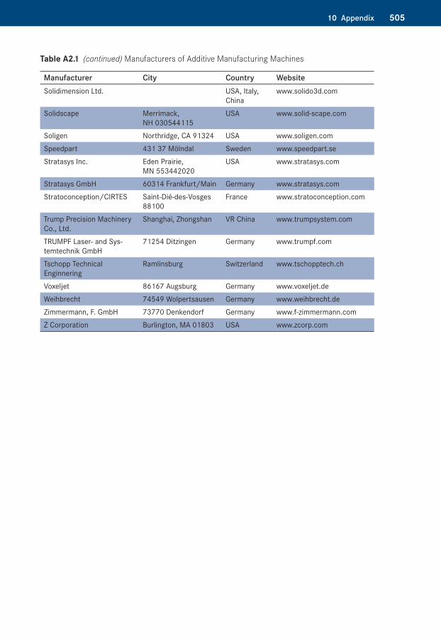
50510 Appendix
Manufacturer City Country WebsiteSolidimension Ltd. USA, Italy,
Chinawww.solido3d.com
Solidscape Merrimack, NH 030544115
USA www.solid-scape.com
Soligen Northridge, CA 91324 USA www.soligen.comSpeedpart 431 37 Mölndal Sweden www.speedpart.seStratasys Inc. Eden Prairie,
MN 553442020 USA www.stratasys.com
Stratasys GmbH 60314 Frankfurt/Main Germany www.stratasys.comStratoconception/CIRTES Saint-Dié-des-Vosges
88100France www.stratoconception.com
Trump Precision Machinery Co., Ltd.
Shanghai, Zhongshan VR China www.trumpsystem.com
TRUMPF Laser- and Sys-temtechnik GmbH
71254 Ditzingen Germany www.trumpf.com
Tschopp Technical Enginnering
Ramlinsburg Switzerland www.tschopptech.ch
Voxeljet 86167 Augsburg Germany www.voxeljet.deWeihbrecht 74549 Wolpertsausen Germany www.weihbrecht.deZimmermann, F. GmbH 73770 Denkendorf Germany www.f-zimmermann.comZ Corporation Burlington, MA 01803 USA www.zcorp.com
Table A2.1�(continued) Manufacturers of Additive Manufacturing Machines
506 10 Appendix
Table A2.2�Stereolithography Machines I
RP Process Unit SL SL SL SL SL*Machine Designation/Type
SLA 250 SLA 5000 SLA 7000 Viper-SLA Viper Pro
Manufacturer 3D Systems Distribution in Germany www.3dsystems.comDimensions, Connection valuesWidth/depth/height m/m/m 1.24/1.64/0.69 1.88/1.19/2.02 1.88/1.22/2.03 1.34/0.86/1.78 ca. 2/1.5/2Weight Kg 362 1318 1196 463Electrical connection V/A 230/8 200–240/15 200–140/20 220–240/16 200–140/20Power consumption kW 1.2 2.2 3 1.51 3Working gas l/min – – – – –Cooling water l/min – – – – –Extraction m3/h – – – – –Work room temperature °C 20–26 20–26 20–26 20–26 20–26Relative moisture % < 50 < 50 < 50 < 50 < 50ProcessFumes, Exhaust Closed system with active carbon filterDisposal, Waste Cured polymerHazardous Waste Uncured polymer, solventContouring ElementKind Laser Laser Laser Laser LaserType HeCd Nd:YV04 Nd:YV04 Nd:YV04 Nd:YV04
x-y Contour generation Scanner Scanner Scanner Scanner Scannerx-y Contour accuracy mm Depending on
the materialDepending on the material
Depending on the material
Depending on the material
Depending on the material
Position repeatability mm – 0.013 0.001 0.0076 0.0076z Contour accuracy mm 0.0025 0.00177 0.00125 0.0025 0.0025z Contour repeatable accuracy
mm Depending on the material
Depending on the material
Depending on the material
Depending on the material
Depending on the material
Coating cycle s Depending on geometry
Depending on geometry
Depending on geometry
Depending on geometry
Depending on geometry
Coating arm speed mm/s Typ. 25–50 Typ. 25–50 Typ. 25–50 Typ. 25–50 Typ. 25–50Power fluctuation % ± 5 ± 5 ± 5 ± 5 ± 5Model characteristicsInstallation space max. (Width/depth/height)
mm 254/254/254 508/508/584 508/508/600 254/254/254 min: 650/350/300 max: 1500/750/500
Model dimensions max. mm 254/254/254 508/508/584 508/508/600 254/254/254Layer thickness mm 0.075–0.15 0.05–0.15 0.025–0.15 0.025–0.15 0.05–0.15Spot (laser diameter) mm ca. 0.25 ca. 0.25 ca. 0.25 plus
0.8ca. 0.075 plus .25
0.13
Accuracy absolute mm 0.1 0.1 0.1 0.1 0.1Repeatability mm – – – – –Additional support yes yes yes yes yesEDP interfacesInterfaces format STL, SLC STL, SLC STL, SLC STL, SLC STL, SLCEDP system PC PC PC PC PCOperating system MS-DOS Windows XP Windows XP Windows XP Windows XPSoftware Buildstation 4.0 Buildstation 5.5 Buildstation 5.5 Buildstation 5.5 Buildstation 5.5
* The technical data, especially the building chambers, change with the equipment of the machine.
50710 Appendix
Table A2.3�Stereolithography Machines II
RP Process Unit Stereolithography Stereolithography SLMachine designation/Type InVision 3-D Printer InVision HR 3-D Printer FS-Realizer STLManufacturer 3D Systems F&S Stereolitho-
graphytechnik GmbHDistribution in Germany www.3dsystems.comDimensions, Connection valuesWidth/depth/height m/m/m 0.96/1.42/1.67 0.96/1.42/1.67 1.6/0.8/2.3Weight kg 254 254 500Electrical connection V/A 100–127/15; 200–240/10 100–127/15; 200–240/10 230/16; 400/32Power consumption kW 1.5Working gas l/min –Cooling water l/min –Extraction m3/h yesWork room temperature °C 18–28 < 33Relative moisture % 45ProcessFumes, Exhaust lowDisposal, WasteHazardous wasteContouring ElementKind Multijet Modeling Multijet Modeling LaserType with UV curing with UV curing Nd-YAGx-y Contour generation Scannerx-y Contour accuracy dpi 328/328 656/656 ± 0.02Spot repeatability dpi 0.002z Contour accuracy dpi 606 800 ± 0.1z Contour repeatable accuracy
mm ± 0.1
Coating cycle s < 10Coating arm speed mm/s 0–1000Power fluctuation % ± 2Model characteristicsInstallation space max. (width/depth/height)
mm 127/178/50 400/400/300
Model dimensions max. mm 298/185/203 64.5 cm2 (x, y); 5.0 cm (z) 400/400/300Layer thickness mm > 0.1Gauge mm 0.1Accuracy absolute mm ± 0.1Repeatability mm ± 0.1Additional support yesEDP InterfaceInterface formats Ethernet, .stl F&SEDP System PCOperating system Windows XP, Professional,
2000, NTWindows XP, Professional, 2000, NT
Win NT
Software InVision print client software InVision print client software F&S
508 10 Appendix
Table A2.4�Stereolithography Machines III
RP Process Unit SL SL SL SL SL*Machine designation/Type
DigitalWax 008J DigitalWax 009J DigitalWax 028J DigitalWax 028J+
DigitalWax 029J
Manufacturer DWS Additive Manufacturing Distribution www.dwssystems.comDimensions, Connection valuesWidth/depth/height m/m/m 0.38/0.52/0.56 0.38/0.52/0.56 0.38/0.52/0.73 0.38/0.52/0.73 0.61/0.66/1.4Weight kg 43 43 56 56 150Electrical connection V/A 230/115 230/115 230/115 230/115 230/115Power consumption kW 0.2 0.2 0.4 0.4 0.5Working gas l/min – – – – –Cooling water l/min – – – – –Extraction m3/h – – – – –Work room temperature °C 22–25 22–25 22–25 22–25 22–25Relative moisture % 60 60 60 60 60ProcessFumes. Exhaust –Disposal, Waste –Hazardous waste –Contouring ElementKind Laser Laser Laser Laser LaserType Solid State
BluEdge® BE-100
Solid State BluEdge® BE-
Solid State BluEdge® BE-1500A/BE-1500AHR
Solid State BluEdge® BE-1500A/BE-1500AHR
Solid State BluEdge® BE-1700/BE-1700HR
x-y Contour generation Plotter DLP® Texas Instruments Inc.
Galvanometer Galvanometer Galvanometer
x-y Contour accuracy mm Depending on the material
Depending on the material
Depending on the material
Depending on the material
Depending on the material
Position repeatability mm – – – – –z Contour accuracy mm – – – – –z Contour repeatable accuracy
mm Depending on the material
Depending on the material
Depending on the material
Depending on the material
Depending on the material
Coating cycle s Depending on geometry
Depending on geometry
Depending on geometry
Depending on geometry
Depending on geometry
Coating arm speed mm/s Typ. 0-40 – Typ. 0-2200 Typ. 0-2200 Typ. 2600Power fluctuation % – – – – –Model characteristicsInstallation space max. (width/depth/height)
mm 65/65/90 50/37/90 65/65/90 90/90/90 110/110/100
Model dimensions max. mm 65/65/90 50/37/90 65/65/90 90/90/90 110/110/110Layer thickness mm 0.01–0.10 0.01–0.10 0.01–0.10 0.01–0.10 0.01–0.10Spot (laser diameter) mm – – – – –Accuracy absolute mm – – – – –Repeatability mm – – – – –Additional support yes yes yes yes yesEDP InterfaceInterface formats STL, SLC STL, SLC STL, SLC STL, SLC STL, SLCEDP system PC PC PC PC PCOperating system 32-bit Windows
XP Pro, Vista, 7Windows XP Windows 7 Windows 7 Windows 7
Software DigitalWax 008J Controller
DigitalWax 009J Controller
DigitalWax 028J Controller
DigitalWax 028J Controller
DigitalWax 029J Controller
50910 Appendix
Table A2.5�Stereolithography Machines IV
RP Process Unit SL SL SL SL SL*Machine designation/Type
DigitalWax 029J+
DigitalWax 030J DigitalWax dfab DigitalWax 008D
DigitalWax 020D
Manufacturer DWS Additive Manufacturing Distribution www.dwssystems.comDimensions, Connection valuesWidth/depth/height m/m/m 0.61/0.66/1.4 1.15/1.45/2.1 – 0.38/0.52/0.56 0.38/0.52/0.81Weight kg 150 – – 45 58Electrical connection V/A 230/115 230/115 – 230/115 230/115Power consumption kW 0.5 – – 0.2 0.4Working gas l/min – – – – –Cooling water l/min – – – – –Extraction m3/h – – – – –Work room temperature °C 22–25 22–25 22–25 22–25 22–25Relative moisture % 60 60 60 60 60ProcessFumes, Exhaust –Disposal, Waste –Hazardous waste –Contouring ElementKind Laser Laser Laser Laser LaserType Solid State
BluEdge® BE-1800A/BE-1800AHR
Solid State Blu Edge®
– Solid State Blu Edge® BE-1000
Solid State Blu Edge® BE-1500C
x-y Contour generation Galvanometer – – Plotter Galvanometerx-y Contour accuracy mm Depending on
the materialDepending on the material
Depending on the material
Depending on the material
Depending on the material
Position repeatability mm – – – – –z Contour accuracy mm – – – – –z Contour repeatable accuracy
mm Depending on the material
Depending on the material
Depending on the material
Depending on the material
Depending on the material
Coating cycle s Depending on geometry
Depending on geometry
Depending on geometry
Depending on geometry
Depending on geometry
Coating arm speed mm/s Typ. 5000 – – Typ. 0–40 Typ. 0–2000Power fluctuation % – – – – –Model characteristicsInstallation space max. (width/depth/height)
mm 150/150/100 300/300/300 – 65/65/90 130/130/90
Model dimensions max. mm 150/150/100 300/300/300 – 65/65/90 130/130/90Layer thickness mm 0.01–0.10 – – 0.01–0.10 0.01–0.10Spot (laser diameter) mm – – – – –Accuracy absolute mm – – – – –Repeatability mm – – – – –Additional support yes yes yes yes yesEDP InterfaceInterface formats STL, SLC STL, SLC STL, SLC STL, SLC STL, SLCEDP system PC PC PC PC PCOperating system Windows 7 – – 32-bit Windows
XP Pro, Vista, 7Windows XP Professional
Software DigitalWax 029J Controller
DigitalWax 030J Controller
– DigitalWax 008D Controller
DigitalWax 008D Controller
510 10 Appendix
Table A2.6�Stereolithography Machines V
RP Process Unit SL SL SL SL SL*Machine designation/Type
DigitalWax 028D
DigitalWax 029D
DigitalWax 030D
DigitalWax 029X DigitalWax 030X
Manufacturer DWS Additive Manufacturing Distribution www.dwssystems.comDimensions, Connection valuesWidth/depth/height m/m/m 0.38/0.52/0.73 0.61/0.66/1.4 1.1/0.7/2.0 0.61/0.66/1.4 1.15/1.45/2.1Weight kg 56 150 – 150 –Electrical connection V/A 230/115 230/115 230/115 230/115 230/115Power consumption kW 0.4 0.5 – 0.5 –Working gas l/min – – – – –Cooling water l/min – – – – –Extraction m3/h – – – – –Work room temperature °C 22–25 22–25 22–25 22–25 22–25Relative moisture % 60 60 60 60 60ProcessFumes, Exhaust –Disposal, Waste –Hazardous waste –Contouring ElementKind Laser Laser Laser Laser LaserType Solid State
BluEdge® BE-1500
Solid State Blu Edge® BE- 1800B
Solid State Blu Edge®
Solid State Blu Edge® BE- 1800C
Solid State Blu Edge®
x-y Contour generation Galvanometer Galvanometer – Galvanometer –x-y Contour accuracy mm Depending on
the materialDepending on the material
Depending on the material
Depending on the material
Depending on the material
Position repeatability mm – – – – –z Contour accuracy mm – – – – –z Contour repeatable accuracy
mm Depending on the material
Depending on the material
Depending on the material
Depending on the material
Depending on the material
Coating cycle s Depending on geometry
Depending on geometry
Depending on geometry
Depending on geometry
Depending on geometry
Coating arm speed mm/s Typ. 0–2000 Typ. 5000 – Typ. 5000 –Power fluctuation % – – – – –Model characteristicsInstallation space max. (width/depth/height)
mm 90/90/90 150/150/150 250/250/250 150/150/150 300/300/300
Model dimensions max. mm 90/90/90 150/150/150 250/250/250 150/150/150 300/300/300Layer thickness mm 0.01–0.10 0.01–0.10 0.01–0.10 0.01–0.10 0.01–0.10Spot (laser diameter) mm – – – – –Accuracy absolute mm – – – – –Repeatability mm – – – – –Additional support yes yes yes yes yesEDP InterfaceInterface formats STL, SLC STL, SLC STL, SLC STL, SLC STL, SLCEDP system PC PC PC PC PCOperating system Windows XP
ProfessionalWindows XP Professional
Windows Windows 7 Windows 7
Software DigitalWax 028D Controller
DigitalWax 029D Controller
DigitalWax 030D Controller
DigitalWax 029X Controller
DigitalWax 030X Controller
51110 Appendix
Table A2.7�Stereolithography Machines VI
RP Process Unit SLA SLA SLA SLA SLAMachine designation/Type
Perfactory Micro
Perfactory Micro DDP
Perfactory Micro EDU
Perfactory Aureus
PixCera
Manufacturer EnvisionTEC GmbHDistribution Envisiontec.comDimensions, Connection valuesWidth/depth/height m/m/m 0.23/0.18/0.58 0.23/0.23/0.52 0.28/0.25/0.61 0.45/0.78/0.45 0.45/0.78/0.45Weight kg 13 13 11 35 35Electrical connection V/A 100-240/2-3 100-240/2-3 100-240/2-3 100-240/1-2 100-240/1-2Capacity KW n. a. n. a. n. a. n. a. n. a.Work room temperature °C n. a. n. a. n. a. n. a. n. a.Air moisture % n. a. n. a. n. a. n. a. n. a.Model characteristicsInstallation space max. (width/depth/height)
mm 40/30/100 40/30/100 86/64.5/100 60/45/100 60/45/100
Model dimensions max. mm 40/30/100 40/30/100 86/64.5/100 60/45/100 60/45/100Layer thickness mm 0.025–0.035 0.05/0.1 0.025–0.1 0.025–0.035 0.025–0.035Accuracy absolute mm n. a. n. a. n. a. n. a. n. a.EDP InterfaceInterface formats STL STL STL STL STLEDP system n. a. n. a. n. a. PC PCOperating system n. a. n. a. n. a. n. a. n. a.MiscellaneousBuilding materials PIC 100,
EC500, HTM140
Press-E-Cast LS 600, HTM140V2
R5/R11, PIC 100/100G, WIC 100G, EC500, RCP30/130, HTM140
E-Dent, E-PKin-dial, Press-E-Cast
ERM pixel resolution mm 0.031 - - - -Resolution in x and y mm - 0.075 - - -Native pixel size mm - - 0.084 0.043 0.043Linear z-axis resolution mm 0.001 - 0.001 - -
512 10 Appendix
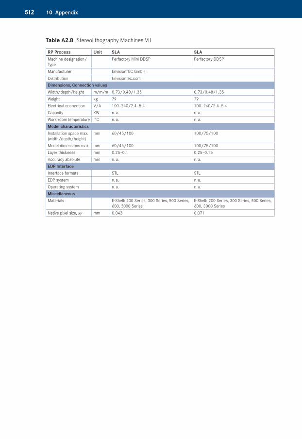
Table A2.8�Stereolithography Machines VII
RP Process Unit SLA SLAMachine designation/Type
Perfactory Mini DDSP Perfactory DDSP
Manufacturer EnvisionTEC GmbHDistribution Envisiontec.comDimensions, Connection valuesWidth/depth/height m/m/m 0.73/0.48/1.35 0.73/0.48/1.35Weight kg 79 79Electrical connection V/A 100–240/2.4–5.4 100–240/2.4–5.4Capacity KW n. a. n. a.Work room temperature °C n. a. n. a.Model characteristicsInstallation space max. (width/depth/height)
mm 60/45/100 100/75/100
Model dimensions max. mm 60/45/100 100/75/100Layer thickness mm 0.25–0.1 0.25–0.15Accuracy absolute mm n. a. n. a.EDP InterfaceInterface formats STL STLEDP system n. a. n. a.Operating system n. a. n. a.MiscellaneousMaterials E-Shell: 200 Series, 300 Series, 500 Series,
600, 3000 SeriesE-Shell: 200 Series, 300 Series, 500 Series, 600, 3000 Series
Native pixel size, xy mm 0.043 0.071
51310 Appendix
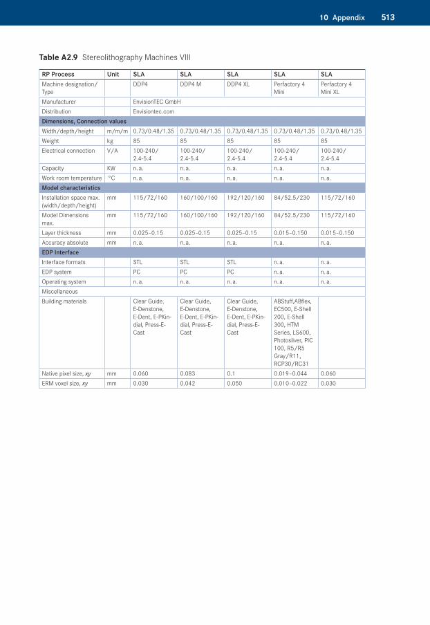
Table A2.9�Stereolithography Machines VIII
RP Process Unit SLA SLA SLA SLA SLAMachine designation/Type
DDP4 DDP4 M DDP4 XL Perfactory 4 Mini
Perfactory 4 Mini XL
Manufacturer EnvisionTEC GmbHDistribution Envisiontec.comDimensions, Connection valuesWidth/depth/height m/m/m 0.73/0.48/1.35 0.73/0.48/1.35 0.73/0.48/1.35 0.73/0.48/1.35 0.73/0.48/1.35Weight kg 85 85 85 85 85Electrical connection V/A 100-240/
2.4-5.4100-240/ 2.4-5.4
100-240/ 2.4-5.4
100-240/ 2.4-5.4
100-240/ 2.4-5.4
Capacity KW n. a. n. a. n. a. n. a. n. a.Work room temperature °C n. a. n. a. n. a. n. a. n. a.Model characteristicsInstallation space max. (width/depth/height)
mm 115/72/160 160/100/160 192/120/160 84/52.5/230 115/72/160
Model Dimensions max.
mm 115/72/160 160/100/160 192/120/160 84/52.5/230 115/72/160
Layer thickness mm 0.025–0.15 0.025–0.15 0.025–0.15 0.015–0.150 0.015–0.150Accuracy absolute mm n. a. n. a. n. a. n. a. n. a.EDP InterfaceInterface formats STL STL STL n. a. n. a.EDP system PC PC PC n. a. n. a.Operating system n. a. n. a. n. a. n. a. n. a.MiscellaneousBuilding materials Clear Guide.
E-Denstone, E-Dent, E-PKin-dial, Press-E-Cast
Clear Guide, E-Denstone, E-Dent, E-PKin-dial, Press-E-Cast
Clear Guide, E-Denstone, E-Dent, E-PKin-dial, Press-E-Cast
ABStuff,ABflex, EC500, E-Shell 200, E-Shell 300, HTM Series, LS600, Photosilver, PIC 100, R5/R5 Gray/R11, RCP30/RC31
Native pixel size, xy mm 0.060 0.083 0.1 0.019–0.044 0.060ERM voxel size, xy mm 0.030 0.042 0.050 0.010–0.022 0.030
514 10 Appendix
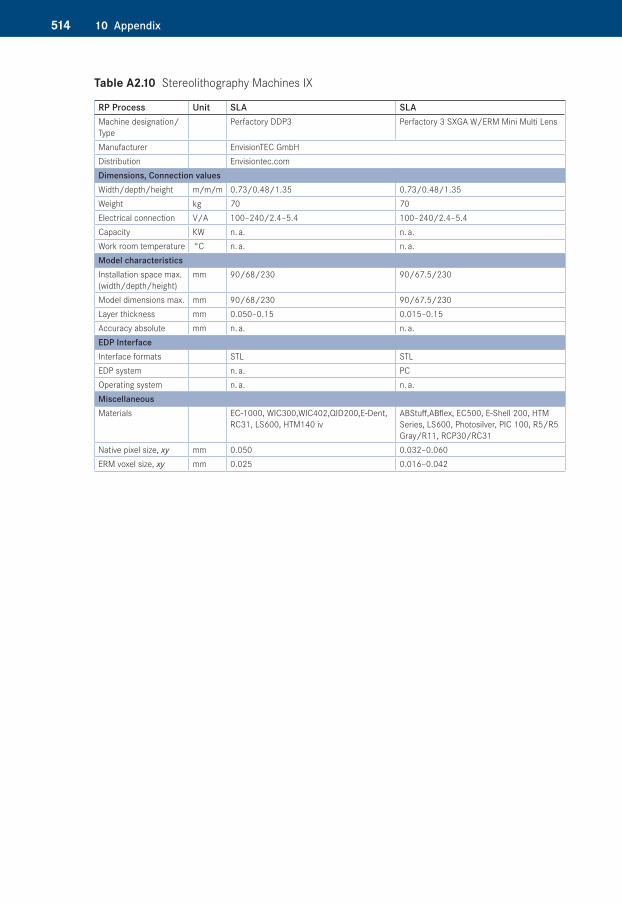
Table A2.10�Stereolithography Machines IX
RP Process Unit SLA SLAMachine designation/Type
Perfactory DDP3 Perfactory 3 SXGA W/ERM Mini Multi Lens
Manufacturer EnvisionTEC GmbHDistribution Envisiontec.comDimensions, Connection valuesWidth/depth/height m/m/m 0.73/0.48/1.35 0.73/0.48/1.35Weight kg 70 70Electrical connection V/A 100–240/2.4–5.4 100–240/2.4–5.4Capacity KW n. a. n. a.Work room temperature °C n. a. n. a.Model characteristicsInstallation space max. (width/depth/height)
mm 90/68/230 90/67.5/230
Model dimensions max. mm 90/68/230 90/67.5/230Layer thickness mm 0.050–0.15 0.015–0.15Accuracy absolute mm n. a. n. a.EDP InterfaceInterface formats STL STLEDP system n. a. PCOperating system n. a. n. a.MiscellaneousMaterials EC-1000, WIC300,WIC402,QID200,E-Dent,
RC31, LS600, HTM140 ivABStuff,ABflex, EC500, E-Shell 200, HTM Series, LS600, Photosilver, PIC 100, R5/R5 Gray/R11, RCP30/RC31
Native pixel size, xy mm 0.050 0.032–0.060ERM voxel size, xy mm 0.025 0.016–0.042
51510 Appendix
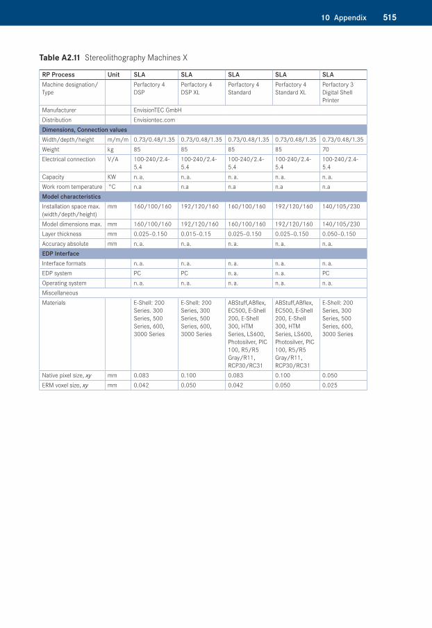
Table A2.11�Stereolithography Machines X
RP Process Unit SLA SLA SLA SLA SLAMachine designation/Type
Perfactory 4 DSP
Perfactory 4 DSP XL
Perfactory 4 Standard
Perfactory 4 Standard XL
Perfactory 3 Digital Shell Printer
Manufacturer EnvisionTEC GmbHDistribution Envisiontec.comDimensions, Connection valuesWidth/depth/height m/m/m 0.73/0.48/1.35 0.73/0.48/1.35 0.73/0.48/1.35 0.73/0.48/1.35 0.73/0.48/1.35Weight kg 85 85 85 85 70Electrical connection V/A 100-240/2.4-
5.4100-240/2.4-5.4
100-240/2.4-5.4
100-240/2.4-5.4
100-240/2.4-5.4
Capacity KW n. a. n. a. n. a. n. a. n. a.Work room temperature °C n.a n.a n.a n.a n.aModel characteristicsInstallation space max. (width/depth/height)
mm 160/100/160 192/120/160 160/100/160 192/120/160 140/105/230
Model dimensions max. mm 160/100/160 192/120/160 160/100/160 192/120/160 140/105/230Layer thickness mm 0.025–0.150 0.015–0.15 0.025–0.150 0.025–0.150 0.050–0.150Accuracy absolute mm n. a. n. a. n. a. n. a. n. a.EDP InterfaceInterface formats n. a. n. a. n. a. n. a. n. a.EDP system PC PC n. a. n. a. PCOperating system n. a. n. a. n. a. n. a. n. a.MiscellaneousMaterials E-Shell: 200
Series. 300 Series, 500 Series, 600, 3000 Series
E-Shell: 200 Series, 300 Series, 500 Series, 600, 3000 Series
ABStuff,ABflex, EC500, E-Shell 200, E-Shell 300, HTM Series, LS600, Photosilver, PIC 100, R5/R5 Gray/R11, RCP30/RC31
ABStuff,ABflex, EC500, E-Shell 200, E-Shell 300, HTM Series, LS600, Photosilver, PIC 100, R5/R5 Gray/R11, RCP30/RC31
E-Shell: 200 Series, 300 Series, 500 Series, 600, 3000 Series
Native pixel size, xy mm 0.083 0.100 0.083 0.100 0.050ERM voxel size, xy mm 0.042 0.050 0.042 0.050 0.025
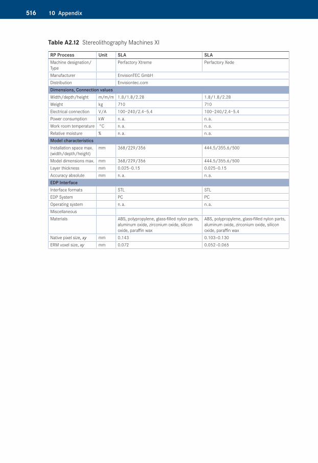
516 10 Appendix
Table A2.12�Stereolithography Machines XI
RP Process Unit SLA SLAMachine designation/Type
Perfactory Xtreme Perfactory Xede
Manufacturer EnvisionTEC GmbHDistribution Envisiontec.comDimensions, Connection valuesWidth/depth/height m/m/m 1.8/1.8/2.28 1.8/1.8/2.28Weight kg 710 710Electrical connection V/A 100−240/2.4−5.4 100−240/2.4−5.4Power consumption kW n. a. n. a.Work room temperature °C n. a. n. a.Relative moisture % n. a. n. a.Model characteristicsInstallation space max. (width/depth/height)
mm 368/229/356 444.5/355.6/500
Model dimensions max. mm 368/229/356 444.5/355.6/500Layer thickness mm 0.025–0.15 0.025–0.15Accuracy absolute mm n. a. n. a.EDP InterfaceInterface formats STL STLEDP System PC PCOperating system n. a. n. a.MiscellaneousMaterials ABS, polypropylene, glass-filled nylon parts,
aluminum oxide, zirconium oxide, silicon oxide, paraffin wax
ABS, polypropylene, glass-filled nylon parts, aluminum oxide, zirconium oxide, silicon oxide, paraffin wax
Native pixel size, xy mm 0.143 0.103–0.130ERM voxel size, xy mm 0.072 0.052–0.065
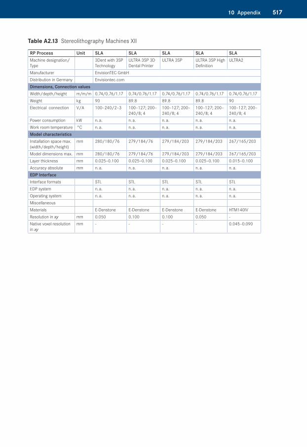
51710 Appendix
Table A2.13�Stereolithography Machines XII
RP Process Unit SLA SLA SLA SLA SLAMachine designation/Type
3Dent with 3SP Technology
ULTRA 3SP 3D Dental Printer
ULTRA 3SP ULTRA 3SP High Definition
ULTRA2
Manufacturer EnvisionTEC GmbHDistribution in Germany Envisiontec.comDimensions, Connection valuesWidth/depth/height m/m/m 0.74/0.76/1.17 0.74/0.76/1.17 0.74/0.76/1.17 0.74/0.76/1.17 0.74/0.76/1.17Weight kg 90 89.8 89.8 89.8 90Electrical connection V/A 100–240/2–3 100–127; 200–
240/8; 4100–127; 200–240/8; 4
100–127; 200–240/8; 4
100–127; 200–240/8; 4
Power consumption kW n. a. n. a. n. a. n. a. n. a.Work room temperature °C n. a. n. a. n. a. n. a. n. a.Model characteristicsInstallation space max. (width/depth/height)
mm 280/180/76 279/184/76 279/184/203 279/184/203 267/165/203
Model dimensions max. mm 280/180/76 279/184/76 279/184/203 279/184/203 267/165/203Layer thickness mm 0.025–0.100 0.025–0.100 0.025–0.100 0.025–0.100 0.015–0.100Accuracy absolute mm n. a. n. a. n. a. n. a. n. a.EDP InterfaceInterface formats STL STL STL STL STLEDP system n. a. n. a. n. a. n. a. n. a.Operating system n. a. n. a. n. a. n. a. n. a.MiscellaneousMaterials E-Denstone E-Denstone E-Denstone E-Denstone HTM140IVResolution in xy mm 0.050 0.100 0.100 0.050 -Native voxel resolution in xy
mm - - - - 0.045–0.090
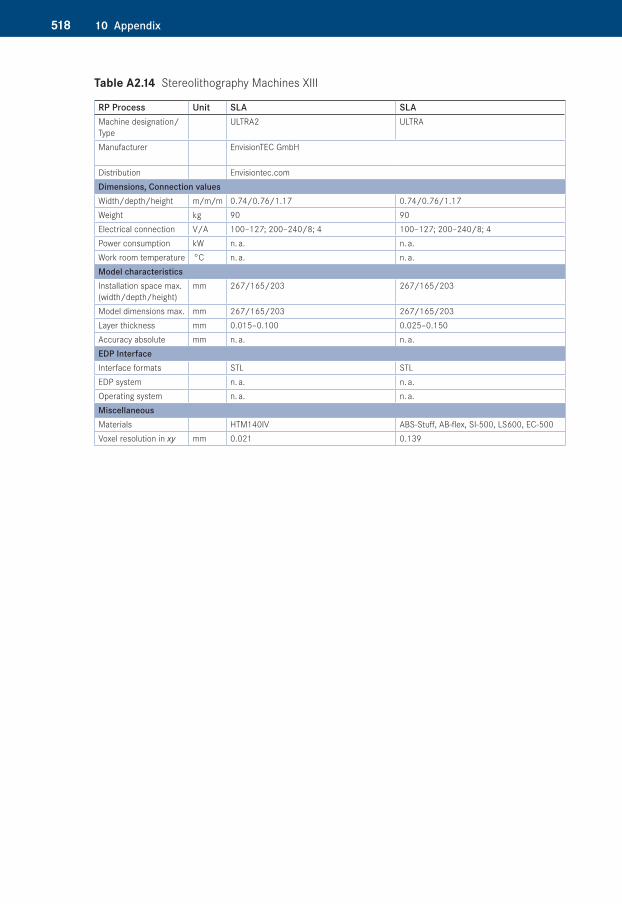
518 10 Appendix
Table A2.14�Stereolithography Machines XIII
RP Process Unit SLA SLAMachine designation/Type
ULTRA2 ULTRA
Manufacturer EnvisionTEC GmbH
Distribution Envisiontec.comDimensions, Connection valuesWidth/depth/height m/m/m 0.74/0.76/1.17 0.74/0.76/1.17Weight kg 90 90Electrical connection V/A 100–127; 200–240/8; 4 100–127; 200–240/8; 4Power consumption kW n. a. n. a.Work room temperature °C n. a. n. a.Model characteristicsInstallation space max. (width/depth/height)
mm 267/165/203 267/165/203
Model dimensions max. mm 267/165/203 267/165/203Layer thickness mm 0.015–0.100 0.025–0.150Accuracy absolute mm n. a. n. a.EDP InterfaceInterface formats STL STLEDP system n. a. n. a.Operating system n. a. n. a.MiscellaneousMaterials HTM140IV ABS-Stuff, AB-flex, SI-500, LS600, EC-500Voxel resolution in xy mm 0.021 0.139
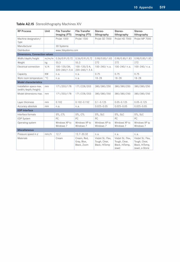
51910 Appendix
Table A2.15�Stereolithography Machines XIV
RP Process Unit File Transfer Imaging (FTI)
File Transfer Imaging (FTI)
Stereolithography
Stereolithography
Stereo lithography
Machine designation/Type
ProJet 1000 ProJet 1500 ProJet SD 7000 ProJet HD 7000 ProJet MP 7000
Manufacturer 3D Systems Distribution www.3dsystems.comDimensions, Connection valuesWidth/depth/height m/m/m 0.56/0.91/0.72 0.56/0.91/0.72 0.98/0.85/1.83 0.98/0.85/1.83 0.98/0.85/1.83Weight kg 55.3 55.3 272 272 272Electrical connection V/A 100–120/3A;
220–240/1.5 A100–120/3 A; 220–240/1.5 A
100–240/ n. a. 100–240/ n. a. 100–240/ n. a.
Capacity KW n. a. n. a. 0.75 0.75 0.75Work room temperature °C n. a. n. a. 18–28 18–28 18–28Model characteristicsInstallation space max. (width/depth/height)
mm 171/203/178 171/228/203 380/380/250 380/380/250 380/380/250
Model dimensions max. mm 171/203/178 171/228/203 380/380/250 380/380/250 380/380/250
Layer thickness mm 0.102 0.102–0.152 0.1–0.125 0.05–0.125 0.05–0.125Accuracy absolute mm n. a. n. a. 0.025–0.05 0.025–0.05 0.025–0.05EDP InterfaceInterface formats STL, CTL STL, CTL STL, SLC STL, SLC STL, SLCEDP System PC PC PC PC PCOperating system Windows XP to
Windows 7Windows XP to Windows 7
Windows XP to Windows 7
Windows XP to Windows 7
Windows XP tp Windows 7
MiscellaneousPressure speed in z mm/h 12.7 12.7–20.32 n. a. n. a. n. a.Materials Cream Cream, Red,
Gray, Blue, Black, Zoom
VisiJet SL: Flex, Tough, Clear, Black, HiTemp
VisiJet SL: Flex, Tough, Clear, Black, HiTemp, Jewel
VisiJet SL: Flex, Tough, Clear, Black, HiTemp, Jewel, e-Stone
520 10 Appendix
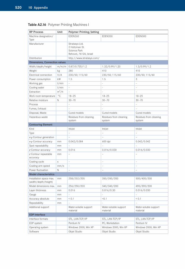
Table A2.16�Polymer Printing Machines I
RP Process Unit Polymer Printing/JettingMachine designation/Type
EDEN260 EDEN350 EDEN500
Manufacturer Stratasys Ltd. 2 Holtzman St. Science Park Rehovot, 76124, Israel
Distribution http://www.stratasys.com/Dimensions, Connection valuesWidth/depth/height m/m/m 0.87/0.735/1.2 1.32/0.99/1.20 1.3/0.99/1.2Weight kg 280 410 410Electrical connection V/A 230/50; 115/60 230/50; 115/60 230/50; 115/60Power consumption kW 1.5 1.5 3Working gas l/min – - –Cooling water l/min – - –Extraction m3/h – - –Work room temperature °C 18–25 18–25 18–25Relative moisture % 30–70 30–70 30–70Process – - –Fumes, Exhaust – - –Disposal, Waste Cured models Cured models Cured modelsHazardous waste Residues from cleaning
systemResidues from cleaning system
Residues from cleaning system
Contouring ElementKind InkJet InkJet InkJetType – – –x-y Contour generation – – –x-y Contour accuracy mm 0.042/0.084 600 dpi 0.042/0.042Spot repeatability mm – – –z Contour accuracy mm 0.016 0.016/0.030 0.016/0.030z Contour repeatable accuracy
mm – – –
Coating cycle s – – –Coating arm speed mm/s – – –Power fluctuation % – – –Model characteristicsInstallation space max. (width/depth/height)
mm 258/252/205 350/350/200 500/400/200
Model dimensions max. mm 256/250/203 340/340/200 490/390/200Layer thickness mm 0.016 0.016/0.30 0.016/0.030Gauge mm – - –Accuracy absolute mm < 0.1 <0.1 < 0.1Repeatability mm – - –Additional support Water-soluble support
materialWater-soluble support material
Water-soluble support material
EDP InterfaceInterface formats STL, LAN-TCP/IP STL, LAN-TCP/IP STL, LAN-TCP/IPEDP system Pentium IV PC, Workstation Pentium IVOperating system Windows 2000, Win XP Windows 2000, Win XP Windows 2000, Win XPSoftware Objet Studio Objet Studio Objet Studio
52110 Appendix
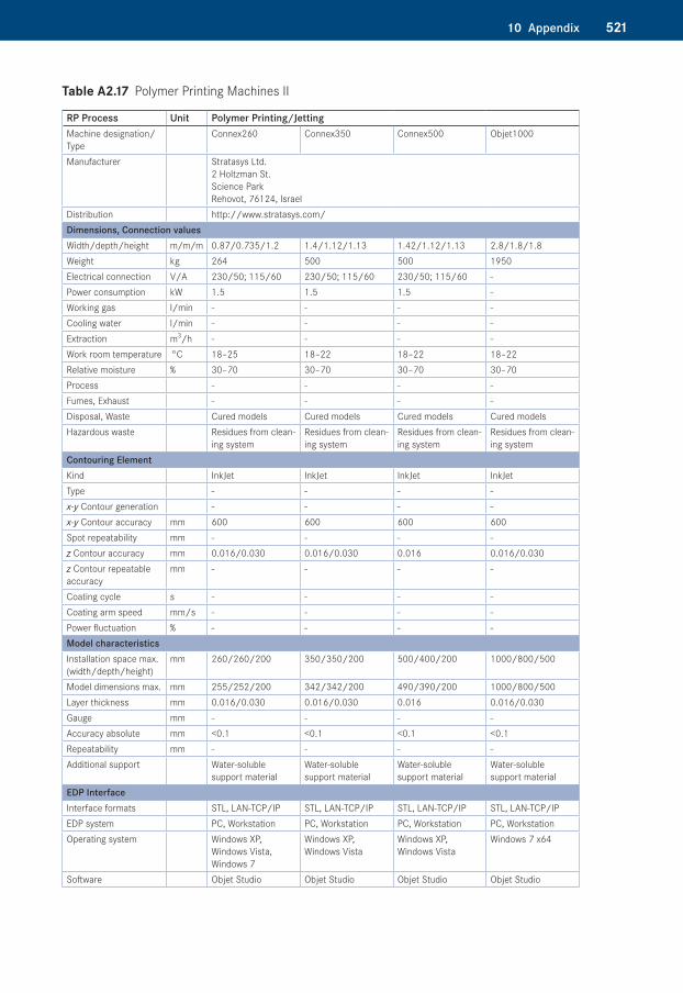
Table A2.17�Polymer Printing Machines II
RP Process Unit Polymer Printing/JettingMachine designation/Type
Connex260 Connex350 Connex500 Objet1000
Manufacturer Stratasys Ltd. 2 Holtzman St. Science Park Rehovot, 76124, Israel
Distribution http://www.stratasys.com/Dimensions, Connection valuesWidth/depth/height m/m/m 0.87/0.735/1.2 1.4/1.12/1.13 1.42/1.12/1.13 2.8/1.8/1.8Weight kg 264 500 500 1950Electrical connection V/A 230/50; 115/60 230/50; 115/60 230/50; 115/60 -Power consumption kW 1.5 1.5 1.5 -Working gas l/min - - - -Cooling water l/min - - - -Extraction m3/h - - - -Work room temperature °C 18–25 18–22 18–22 18–22Relative moisture % 30–70 30–70 30–70 30–70Process - - - -Fumes, Exhaust - - - -Disposal, Waste Cured models Cured models Cured models Cured modelsHazardous waste Residues from clean-
ing systemResidues from clean-ing system
Residues from clean-ing system
Residues from clean-ing system
Contouring ElementKind InkJet InkJet InkJet InkJetType - - - -x-y Contour generation - - - -x-y Contour accuracy mm 600 600 600 600Spot repeatability mm - - - -z Contour accuracy mm 0.016/0.030 0.016/0.030 0.016 0.016/0.030z Contour repeatable accuracy
mm - - - -
Coating cycle s - - - -Coating arm speed mm/s - - - -Power fluctuation % - - - -Model characteristicsInstallation space max. (width/depth/height)
mm 260/260/200 350/350/200 500/400/200 1000/800/500
Model dimensions max. mm 255/252/200 342/342/200 490/390/200 1000/800/500Layer thickness mm 0.016/0.030 0.016/0.030 0.016 0.016/0.030Gauge mm - - - -Accuracy absolute mm <0.1 <0.1 <0.1 <0.1Repeatability mm - - - -Additional support Water-soluble
support materialWater-soluble support material
Water-soluble support material
Water-soluble support material
EDP InterfaceInterface formats STL, LAN-TCP/IP STL, LAN-TCP/IP STL, LAN-TCP/IP STL, LAN-TCP/IPEDP system PC, Workstation PC, Workstation PC, Workstation PC, WorkstationOperating system Windows XP,
Windows Vista, Windows 7
Windows XP, Windows Vista
Windows XP, Windows Vista
Windows 7 x64
Software Objet Studio Objet Studio Objet Studio Objet Studio
522 10 Appendix
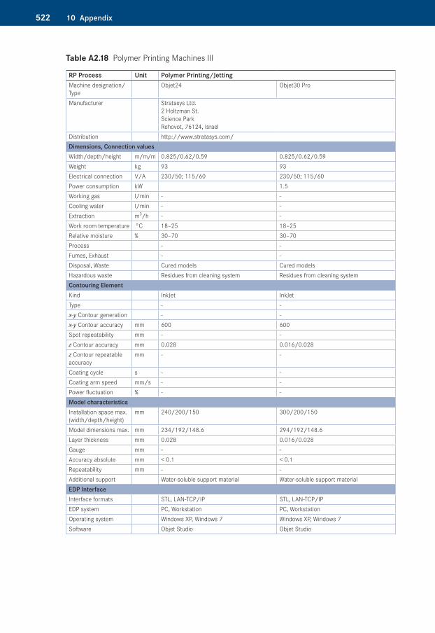
Table A2.18�Polymer Printing Machines III
RP Process Unit Polymer Printing/JettingMachine designation/Type
Objet24 Objet30 Pro
Manufacturer Stratasys Ltd. 2 Holtzman St. Science Park Rehovot, 76124, Israel
Distribution http://www.stratasys.com/Dimensions, Connection valuesWidth/depth/height m/m/m 0.825/0.62/0.59 0.825/0.62/0.59Weight kg 93 93Electrical connection V/A 230/50; 115/60 230/50; 115/60Power consumption kW 1.5Working gas l/min - -Cooling water l/min - -Extraction m3/h - -Work room temperature °C 18–25 18–25Relative moisture % 30–70 30–70Process - -Fumes, Exhaust - -Disposal, Waste Cured models Cured modelsHazardous waste Residues from cleaning system Residues from cleaning systemContouring ElementKind InkJet InkJetType - -x-y Contour generation - -x-y Contour accuracy mm 600 600Spot repeatability mm - -z Contour accuracy mm 0.028 0.016/0.028z Contour repeatable accuracy
mm - -
Coating cycle s - -Coating arm speed mm/s - -Power fluctuation % - -Model characteristicsInstallation space max. (width/depth/height)
mm 240/200/150 300/200/150
Model dimensions max. mm 234/192/148.6 294/192/148.6Layer thickness mm 0.028 0.016/0.028Gauge mm - -Accuracy absolute mm < 0.1 < 0.1Repeatability mm - -Additional support Water-soluble support material Water-soluble support materialEDP InterfaceInterface formats STL, LAN-TCP/IP STL, LAN-TCP/IPEDP system PC, Workstation PC, WorkstationOperating system Windows XP, Windows 7 Windows XP, Windows 7Software Objet Studio Objet Studio
52310 Appendix
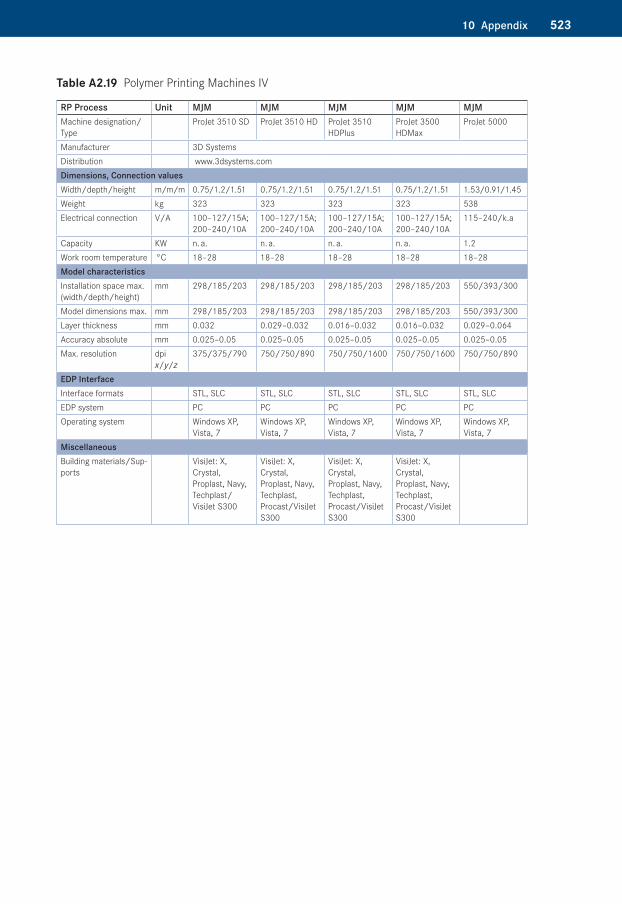
Table A2.19�Polymer Printing Machines IV
RP Process Unit MJM MJM MJM MJM MJMMachine designation/Type
ProJet 3510 SD ProJet 3510 HD ProJet 3510 HDPlus
ProJet 3500 HDMax
ProJet 5000
Manufacturer 3D Systems Distribution www.3dsystems.comDimensions, Connection valuesWidth/depth/height m/m/m 0.75/1.2/1.51 0.75/1.2/1.51 0.75/1.2/1.51 0.75/1.2/1.51 1.53/0.91/1.45Weight kg 323 323 323 323 538Electrical connection V/A 100–127/15A;
200–240/10A100–127/15A; 200–240/10A
100–127/15A; 200–240/10A
100–127/15A; 200–240/10A
115–240/k.a
Capacity KW n. a. n. a. n. a. n. a. 1.2Work room temperature °C 18–28 18–28 18–28 18–28 18–28Model characteristicsInstallation space max. (width/depth/height)
mm 298/185/203 298/185/203 298/185/203 298/185/203 550/393/300
Model dimensions max. mm 298/185/203 298/185/203 298/185/203 298/185/203 550/393/300Layer thickness mm 0.032 0.029–0.032 0.016–0.032 0.016–0.032 0.029–0.064Accuracy absolute mm 0.025–0.05 0.025–0.05 0.025–0.05 0.025–0.05 0.025–0.05Max. resolution dpi
x/y/z375/375/790 750/750/890 750/750/1600 750/750/1600 750/750/890
EDP InterfaceInterface formats STL, SLC STL, SLC STL, SLC STL, SLC STL, SLCEDP system PC PC PC PC PCOperating system Windows XP,
Vista, 7Windows XP, Vista, 7
Windows XP, Vista, 7
Windows XP, Vista, 7
Windows XP, Vista, 7
MiscellaneousBuilding materials/Sup-ports
VisiJet: X, Crystal, Proplast, Navy, Techplast/ VisiJet S300
VisiJet: X, Crystal, Proplast, Navy, Techplast, Procast/VisiJet S300
VisiJet: X, Crystal, Proplast, Navy, Techplast, Procast/VisiJet S300
VisiJet: X, Crystal, Proplast, Navy, Techplast, Procast/VisiJet S300
524 10 Appendix
Table A2.20�Polymer Printing Machines V
RP Process Unit MJM MJM MJM MJMMachine designation/Type
ProJet 3510 CP ProJet 3510 CPX ProJet 3510 CPCPlus ProJet 3500 CPXMax
Area of application RealWax process for precision casting modelsManufacturer 3D Systems
Distribution www.3dsystems.comDimensions, Connection valuesWidth/depth/height m/m/m 0.83/1.43/1.74 0.83/1.43/1.74 0.83/1.43/1.74 0.83/1.43/1.74Weight kg 323 323 323 323Electrical connection V/A 100-127/15A; 200-
240/10A100-127/15A; 200-240/10A
100-127/15A; 200-240/10A
100-127/15A; 200-240/10A
Capacity KW n. a. n. a. n. a. n. a.Work room temperature °C 18–28 18–28 18–28 18–28Model characteristicsInstallation space max. (width/depth/height)
mm 298/185/203 298/185/203 298/185/203 298/185/203
Model dimensions max. mm 298/185/203 298/185/203 298/185/203 298/185/203Layer thickness mm 0.033 0.016–0.033 0.016–0.033 0.016–0.033Accuracy absolute mm 0.025–0.05 0.025–0.05 0.025–0.05 0.025–0.05Max. resolution dpi 375 × 375 × 775 694 × 750 × 1600 694 × 750 × 1600 694 × 750 × 1600EDP InterfaceInterface formats STL, SLC STL, SLC STL, SLC STL, SLCEDP system PC PC PC PCOperating system Windows XP, Vista, 7 Windows XP, Vista, 7 Windows XP, Vista, 7 Windows XP, Vista, 7MiscellaneousBuilding materials/ Supports
VisiJet Prowax/ VisiJet S400
VisiJet Hi-Cast/ VisiJet S400
VisiJet Hi-Cast/ VisiJet S400
VisiJet Hi-Cast/ VisiJet S400
52510 Appendix
Table A2.21�Polymer Printing Machines VI
RP Process Unit MJM MJMMachine designation/Type
ProJet 3510 DP ProJet 3510 MP
Area of application Medical and dental ApplicationsManufacturer 3D Systems Distribution www.3dsystems.comDimensions, Connection valuesWidth/depth/height m/m/m 0.75/1.2/1.51 0.75/1.2/1.51Weight kg 323 323Electrical connection V/A 100-127/15A; 200-240/10A 100-127/15A; 200-240/10ACapacity KW n. a. n. a.Work room temperature °C 18–28 18–28Model characteristicsInstallation space max. (width/depth/height)
mm 298/185/203 298/185/203
Model dimensions max. mm 298/185/203 298/185/203Layer thickness mm 0.029–0.032 0.032Accuracy absolute mm 0.025–0.05 0.025–0.05Max. resolution (x/y/z) dpi 750/750/890 375/375/790EDP InterfaceInterface formats STL, SLC STL, SLCEDP system PC PCOperating system Windows XP, Vista, 7 Windows XP, Vista, 7MiscellaneousBuilding materials/ Supports
VisiJet Dentcast/ VisiJet S300 VisiJet PearlStone, Stoneplast/ VisiJet S300
526 10 Appendix
Table A2.22�Sintering Machines I
RP Process Unit SLM SLMMachine designation/Type
SPro125 SPro250
Manufacturer 3D Systems Distribution www.3dsystems.comDimensions, Connection valuesWidth/depth/height m/m/m 1.35/0.8/1.9 1.7/0.8/2.03Weight kg 900 1100Electrical connection V/A 208/30 3-phase 208/30 3-phasePower consumption kW n. a. n. a.Work room temperature °C n. a. n. a.Relative moisture % n. a. n. a.Contouring ElementKind Laser LaserLaser capacity W 100; 200 200; 400Type n. a. n. a.Max. scan speed mm/s 1000 1000Build speed cm3/h 5–20 5–20Model characteristicsInstallation space max. (width/depth/height)
mm 125/125/125 250/250/320
Model dimensions max. mm 125/125/125 250/250/320Layer thickness mm 0.02–0.1 0.02–0.1Spot (laser diameter) mm 0.035 0.070
52710 Appendix
Table A2.23�Sintering Machines II
RP Process Unit SLS SLS SLS SLS SLSMachine designation/Type
sPro 60 SD sPro 60 HD Base
sPro 60 HD-HS sPro 140 Base sPro 140 HS
Manufacturer 3D Systems Distribution www.3dsystems.comDimensions, Connection valuesWidth/depth/height m/m/m n. a. n. a. n. a. n. a. n. a.Weight kg n. a. n. a. n. a. n. a. n. a.Electrical connection V/A 240/n. a.
3-phase240/n. a. 3-phase
240/n. a. 3-phase
208/n. a. 3-phase
208/n. a. 3-phase
Power consumption kW 12.5 12.5 12.5 17 17Working gas l/min 54 60 108 180 300Contouring ElementKind Laser Laser Laser Laser LaserType CO2 CO2 CO2 CO2 CO2
Imaging system High Torque Scanning Motors (analog)
ProScan™ CX (digital)
ProScan™ DX Dual Mode
ProScan™ DX Digital
ProScan™GX Dual Mode
Scanning speed m/s 5 6 6; 12 10 15Laser capacity W 30 30 70 70 200Model characteristicsInstallation space max. (width/depth/height)
mm 381/330/457 381/330/457 381/330/457 550/550/460 550/550/460
Model dimensions max. mm 381/330/457 381/330/457 381/330/457 550/550/460 550/550/460Layer thickness mm 0.08–0.15 0.08–0.15 0.08–0.15 0.08–0.15 0.08–0.15
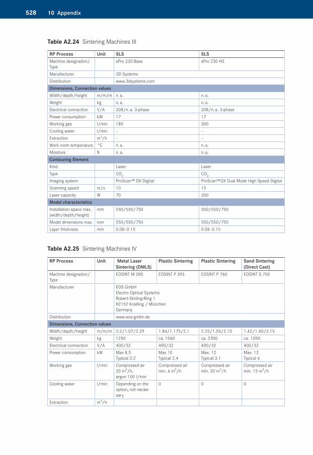
528 10 Appendix
Table A2.24�Sintering Machines III
RP Process Unit SLS SLSMachine designation/Type
sPro 230 Base sPro 230 HS
Manufacturer 3D Systems Distribution www.3dsystems.comDimensions, Connection valuesWidth/depth/height m/m/m n. a. n. a.Weight kg n. a. n. a.Electrical connection V/A 208/n. a. 3-phase 208/n. a. 3-phasePower consumption kW 17 17Working gas l/min 180 300Cooling water l/min – –Extraction m3/h – –Work room temperature °C n. a. n. a.Moisture % n. a. n. a.Contouring ElementKind Laser LaserType CO2 CO2
Imaging system ProScan™ DX Digital ProScan™ GX Dual Mode High Speed DigitalScanning speed m/s 10 15Laser capacity W 70 200Model characteristicsInstallation space max. (width/depth/height)
mm 550/550/750 550/550/750
Model dimensions max. mm 550/550/750 550/550/750Layer thickness mm 0.08–0.15 0.08–0.15
Table A2.25�Sintering Machines IV
RP Process Unit Metal Laser Sintering (DMLS)
Plastic Sintering Plastic Sintering Sand Sintering (Direct Cast)
Machine designation/Type
EOSINT M 280 EOSINT P 395 EOSINT P 760 EOSINT S 750
Manufacturer EOS GmbH Electro Optical Systems Robert-Stirling-Ring 1 82152 Krailling / München Germany
Distribution www.eos-gmbh.deDimensions, Connection valuesWidth/depth/height m/m/m 2.2/1.07/2.29 1.84/1.175/2.1 2.25/1.55/2.10 1.42/1.40/2.15Weight kg 1250 ca. 1060 ca. 2300 ca. 1050Electrical connection V/A 400/32 400/32 400/32 400/32Power consumption kW Max 8.5
Typical 3.2Max 10 Typical 2.4
Max. 12 Typical 3.1
Max. 12 Typical 6
Working gas l/min Compressed air 20 m3/h, argon 100 l/min
Compressed air min. 6 m3/h
Compressed air min. 20 m3/h
Compressed air min. 15 m3/h
Cooling water l/min Depending on the option, not neces-sary
0 0 0
Extraction m3/h
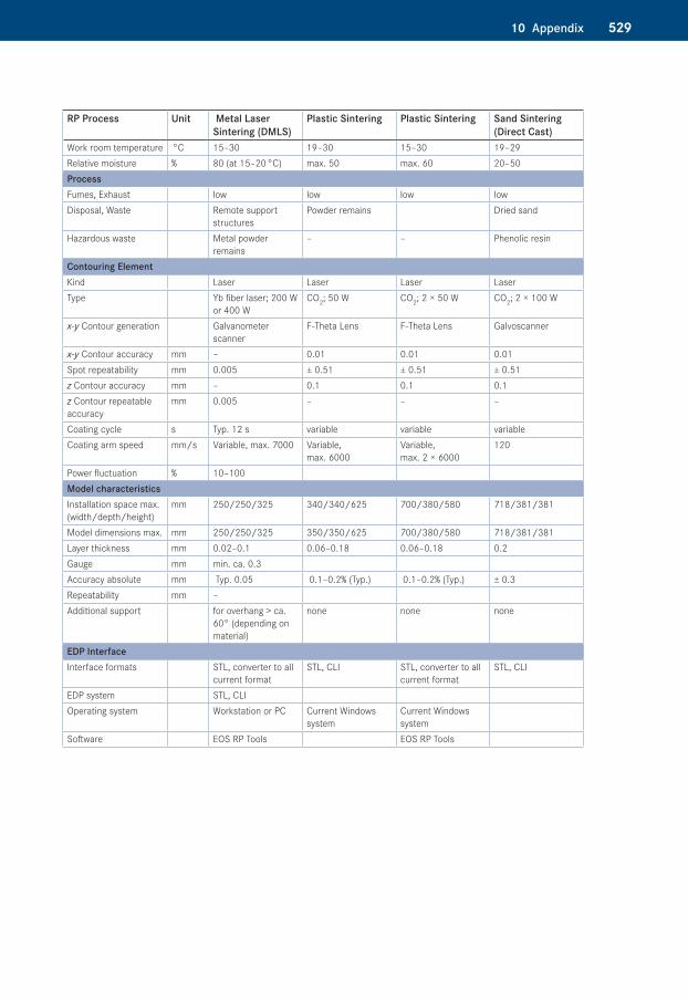
52910 Appendix
RP Process Unit Metal Laser Sintering (DMLS)
Plastic Sintering Plastic Sintering Sand Sintering (Direct Cast)
Work room temperature °C 15–30 19–30 15–30 19–29Relative moisture % 80 (at 15–20 °C) max. 50 max. 60 20–50 ProcessFumes, Exhaust low low low lowDisposal, Waste Remote support
structuresPowder remains Dried sand
Hazardous waste Metal powder remains
– – Phenolic resin
Contouring ElementKind Laser Laser Laser LaserType Yb fiber laser; 200 W
or 400 WCO2; 50 W CO2; 2 × 50 W CO2; 2 × 100 W
x-y Contour generation Galvanometer scanner
F-Theta Lens F-Theta Lens Galvoscanner
x-y Contour accuracy mm – 0.01 0.01 0.01Spot repeatability mm 0.005 ± 0.51 ± 0.51 ± 0.51z Contour accuracy mm – 0.1 0.1 0.1z Contour repeatable accuracy
mm 0.005 – – –
Coating cycle s Typ. 12 s variable variable variableCoating arm speed mm/s Variable, max. 7000 Variable,
max. 6000Variable, max. 2 × 6000
120
Power fluctuation % 10–100Model characteristicsInstallation space max. (width/depth/height)
mm 250/250/325 340/340/625 700/380/580 718/381/381
Model dimensions max. mm 250/250/325 350/350/625 700/380/580 718/381/381Layer thickness mm 0.02–0.1 0.06–0.18 0.06–0.18 0.2Gauge mm min. ca. 0.3Accuracy absolute mm Typ. 0.05 0.1–0.2% (Typ.) 0.1–0.2% (Typ.) ± 0.3Repeatability mm –Additional support for overhang > ca.
60° (depending on material)
none none none
EDP InterfaceInterface formats STL, converter to all
current formatSTL, CLI STL, converter to all
current formatSTL, CLI
EDP system STL, CLIOperating system Workstation or PC Current Windows
systemCurrent Windows system
Software EOS RP Tools EOS RP Tools
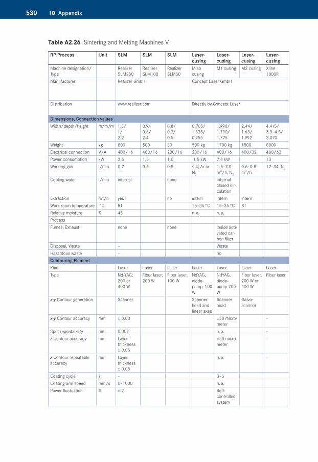
530 10 Appendix
Table A2.26�Sintering and Melting Machines V
RP Process Unit SLM SLM SLM Lasercusing
Lasercusing
Lasercusing
Lasercusing
Machine designation/Type
Realizer SLM250
Realizer SLM100
Realizer SLM50
Mlab cusing
M1 cusing M2 cusing Xline 1000R
Manufacturer Realizer GmbH Concept Laser GmbH
Distribution www.realizer.com Directly by Concept Laser
Dimensions, Connection valuesWidth/depth/height m/m/m 1.8/
1/ 2.2
0.9/ 0.8/ 2.4
0.8/ 0.7/ 0.5
0.705/ 1.833/ 0.955
1.990/ 1.790/ 1.775
2.44/ 1.63/ 1.992
4.415/ 3.9–4.5/ 3.070
Weight kg 800 500 80 500 kg 1700 kg 1500 8000Electrical connection V/A 400/16 400/16 230/16 230/16 400/16 400/32 400/63Power consumption kW 2.5 1.5 1.0 1.5 kW 7.4 kW 13Working gas l/min 0.7 0.6 0.5 < 4; Ar or
N2
1.5–2.0 m3/h; N2
0.6–0.8 m3/h
17–34; N2
Cooling water l/min internal none Internal closed cir-culation
Extraction m3/h yes no intern intern internWork room temperature °C RT 15–35 °C 15–35 °C RTRelative moisture % 45 n. a. n. a.ProcessFumes, Exhaust none none Inside acti-
vated car-bon filter
Disposal, Waste – WasteHazardous waste – noContouring ElementKind Laser Laser Laser Laser Laser Laser LaserType Nd-YAG;
200 or 400 W
Fiber laser; 200 W
Fiber laser, 100 W
NdYAG, diode-pump, 100 W
NdYAG, diode-pump 200 W
Fiber laser, 200 W or 400 W
Fiber laser
x-y Contour generation Scanner Scanner head and linear axes
Scanner head
Galvo-scanner
x-y Contour accuracy mm ± 0.03 ±50 micro-meter
-
Spot repeatability mm 0.002 n. a. -z Contour accuracy mm Layer
thickness ± 0.05
±50 micro-meter
-
z Contour repeatable accuracy
mm Layer thickness ± 0.05
n. a. -
Coating cycle s – 3–5Coating arm speed mm/s 0–1000 n. a.Power fluctuation % ± 2 Self-
controlled system
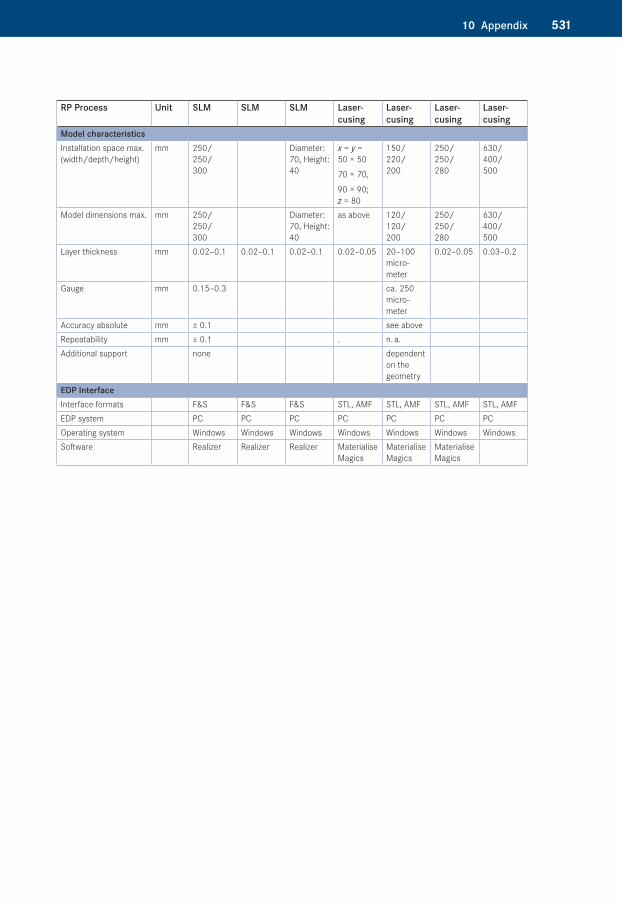
53110 Appendix
RP Process Unit SLM SLM SLM Lasercusing
Lasercusing
Lasercusing
Lasercusing
Model characteristicsInstallation space max. (width/depth/height)
mm 250/ 250/ 300
Diameter: 70, Height: 40
x = y = 50 × 50
70 × 70,
90 × 90; z = 80
150/ 220/ 200
250/ 250/ 280
630/ 400/ 500
Model dimensions max. mm 250/ 250/ 300
Diameter: 70, Height: 40
as above 120/ 120/ 200
250/ 250/ 280
630/ 400/ 500
Layer thickness mm 0.02–0.1 0.02–0.1 0.02–0.1 0.02–0.05 20–100 micro-meter
0.02–0.05 0.03–0.2
Gauge mm 0.15–0.3 ca. 250 micro-meter
Accuracy absolute mm ± 0.1 see aboveRepeatability mm ± 0.1 . n. a.Additional support none dependent
on the geometry
EDP InterfaceInterface formats F&S F&S F&S STL, AMF STL, AMF STL, AMF STL, AMF EDP system PC PC PC PC PC PC PCOperating system Windows Windows Windows Windows Windows Windows WindowsSoftware Realizer Realizer Realizer Materialise
MagicsMaterialise Magics
Materialise Magics
532 10 Appendix
Table A2.27�Sintering and Melting Machines VI
RP Process Unit Laser melting
Laser melting
Beam melting
Beam melting
Beam melting
Beam melting
Machine designation/Type
AM125 AM250 SLM® 125 HL
SLM® 250 HL
SLM® 500 HL
SLM® 280 HL
Manufacturer Renishaw GmbH Karl-Benz Straße 12 72124 Pliezhausen Deutschland (Germany) www.renishaw.com
SLM Solutions GmbH Roggenhorster Straße 9c 23556 Lübeck (Germany) www.slm-solutions.com
Distribution Directly by Renishaw Directly by SLM SolutionsDimensions, Connection valuesWidth/depth/height m/m/m 1.35/0.8/
1.91.7/0.8/ 2.025
1.35/0.8/ 1.9(2.4)
1.650/1.0/ 1.9(2.4)
3.0/1.5/ 2.0(2.5)
1.8/1.0/ 1.9(2.4)
Weight kg 900 1100 700 850 2000 1000Electrical connection V/A 230/16 230/16 400/32 400/32 400/32 400/32Power consumption kW 4 5 8 6Working gas l/min 0.5 (Flush-
ing: 1000 l); Ar or N2
1.5 (Flush-ing: 1500 l); Ar or N2
3.0 (Flush-ing: 2000 l); Ar or N2
2.5 (Flush-ing: 1700 l); Ar or N2
Cooling water l/minExtraction m3/hWork room tempera-ture
°C
Relative moisture %ProcessFumes, ExhaustDisposal, WasteHazardous wasteContouring ElementKind Laser Laser Laser Laser Laser LaserType 100 W or
200 W200 W or 400 W
YLR fiber laser; 100 W or 200 W
YLR fiber laser; 200 W or 400 W
2 × YLR fiber laser; 1 × 400 W, 1 × 1000 W
YLR fiber laser; 1 × 400 W, 1 × 1000 W
x-y Contour generationx-y Contour accuracy mmSpot repeatability mmz Contour accuracy mmz Contour repeatable accuracy
mm
Coating cycle sCoating arm speed mm/sPower fluctuation %Model characteristicsInstallation space max. (width/depth/height)
mm 120/120/ 125
245/245/ 300 (z = 360 mm on demand)
125/125/ 75 (125)
248/248/ 250 (350)
500/280/ 325
280/280/ 350
Model dimensions max. mm 120/120/ 125
245/245/ 300 (z = 360 mm on demand)
125/125/ 75 (125)
248/248/ 250 (350)
500/280/ 325
280/280/ 350
Layer thickness mm 0.02–0.1 0.02–0.1 0.02–0.075 0.02–0.075 0.02–0.2 0.02–0.15Gauge mm min. 0.140 min. 0.150 min. 0.180 min. 0.2Accuracy absolute mm
53310 Appendix
RP Process Unit Laser melting
Laser melting
Beam melting
Beam melting
Beam melting
Beam melting
Repeatability mmAdditional supportEDP InterfaceInterface formats STL, AMF STL, AMF
PC PC PC PC PC PCWindows Windows Windows Windows Windows WindowsMaterialise, Marcam Autofab
Materialise, Marcam Auto fab
Auto Fab MC AutoFabMC AutoFabMC AutoFabMC
Table A2.28�Sintering Machines VII
RP Process Unit Electron beam melting (EBM)
Electron beam melting (EBM)
SLM SLM SLM
Machine designation/Type
Q10 A2 PXS PXM PXL
Manufacturer Arcam AB Krokslätts Fabriker 27A SE 431 37 Mölndal Sweden
Phenix Systems Parc Européen d’Entreprises Rue Richard Wagner 63200 Riom Frankreich, France
Distribution Directly by ARCAMDimensions, Connection valuesWidth/depth/height m/m/m 1.85/0.9/2.2 1.85/0.9/2.2 1.2/0.77/1.95 1.2/1.5/1.95 2.4/2.2/2.4Weight kg 1420 1420 1000 1500 5000Electrical connection V/A 3 × 400/32 3 × 400/32 230 400 400Power consumption kW 7 7 3 kVA 10 kVA 15 kVAWorking gas l/min 1 l/h;
He 50–75 l cooldown
6–8 bar compressed air
6–8 bar compressed air
6–8 bar compressed air
Cooling water l/minExtraction m3/hWork room temperature °CRelative moisture %ProcessFumes, ExhaustDisposal, WasteHazardous wasteContouring ElementKind Electron beam Electron beam Laser Laser LaserType Single crystal-
line CeB6
Fiber laser; 50 W; 1070 nm
Fiber laser; 300 W; 1070 nm
Fiber laser; 500 W; 1070 nm
x-y Contour generationx-y Contour accuracy mm 0.13–0.2Spot repeatability mmz Contour accuracy mmz Contour repeatable accuracy
mm
Coating cycle sCoating arm speed mm/sPower fluctuation %
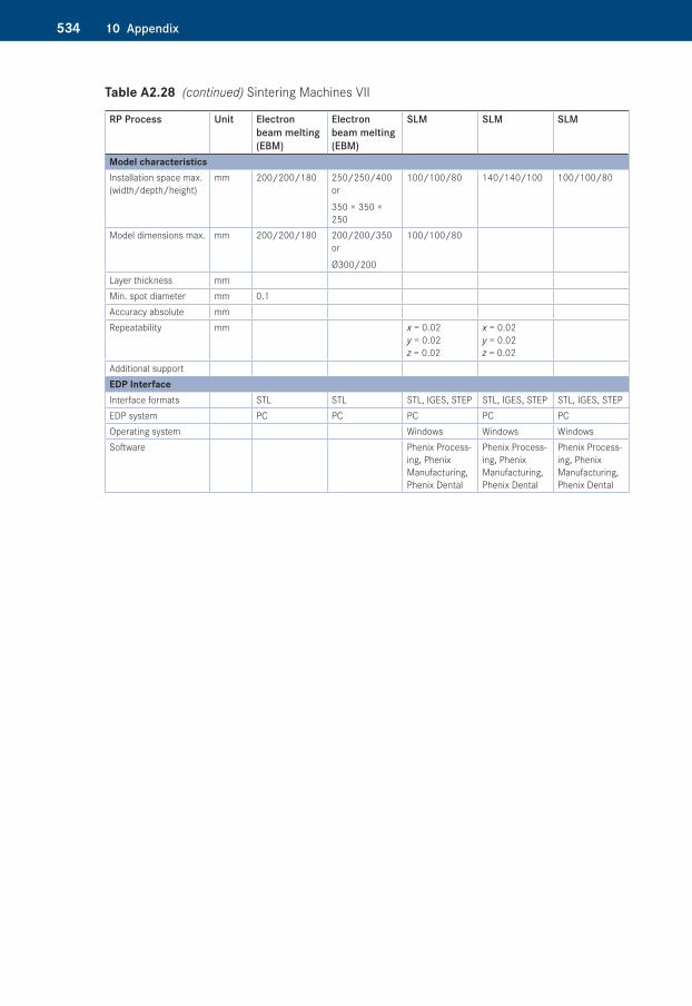
534 10 Appendix
RP Process Unit Electron beam melting (EBM)
Electron beam melting (EBM)
SLM SLM SLM
Model characteristicsInstallation space max. (width/depth/height)
mm 200/200/180 250/250/400 or
350 × 350 × 250
100/100/80 140/140/100 100/100/80
Model dimensions max. mm 200/200/180 200/200/350 or
Ø300/200
100/100/80
Layer thickness mmMin. spot diameter mm 0.1Accuracy absolute mmRepeatability mm x = 0.02
y = 0.02 z = 0.02
x = 0.02 y = 0.02 z = 0.02
Additional supportEDP InterfaceInterface formats STL STL STL, IGES, STEP STL, IGES, STEP STL, IGES, STEPEDP system PC PC PC PC PCOperating system Windows Windows WindowsSoftware Phenix Process-
ing, Phenix Manufacturing, Phenix Dental
Phenix Process-ing, Phenix Manufacturing, Phenix Dental
Phenix Process-ing, Phenix Manufacturing, Phenix Dental
Table A2.28�(continued) Sintering Machines VII
53510 Appendix
Table A2.29�Extrusion Machines I
RP Process Unit Extrusion Extrusion Extrusion ExtrusionMachine designation/Type
Mojo 3D Printer uPrint SE / Plus Dimension 1200es Dimension Elite
Manufacturer Stratasys Inc., USADistribution www.stratasys.comDimensions, Connection valuesWidth/depth/height m/m/m 0.63/0.45/0.53 0.635/0.66/0.787 0.838/0.737/1.143 0.686/0.914/1.041Weight kg 27 76 148 136Electrical connection V/A 120/6; 230/2.5 120/15; 230/7 120/15; 230/7 120/15; 230/7Power consumption kW n. a. n. a. n. a. n. a.Working gas l/min – – – –Cooling water l/min – – – –Extraction m3/h – – – –Work room temperature °C n. a. n. a. n. a. n. a.Relative moisture % n. a. n. a. n. a. n. a.ProcessFumes, Exhaust – – – –Disposal, Waste yes yes yes yesHazardous waste – – – –Contouring ElementKind Extruder Extruder Extruder ExtruderTypex-y Contour generation Belt drive xy Belt drive xy Belt drive xy Belt drive xyx-y Contour accuracy mm n. a. n. a. n. a. n. a.Spot repeatability mm – – – –z Contour accuracy mm n. a. n. a. n. a. n. a.z Contour repeatable accuracy
mm n. a. n. a. n. a. n. a.
Coating cycle s 0 0 0 0Coating arm speed mm/s – – – –Power fluctuation % 0 0 0 0Model characteristicsInstallation space max. (width/depth/height)
mm 127/127/127 203/152/152 254/254/305 203/203/305
Model dimensions max. mm 127/127/127 203/152/152 254/254/305 203/203/305Layer thickness mm 0.178 0.254 0.33; 0.254 0.254; 0.178Gauge mm n. a. n. a. n. a. n. a.Accuracy absolute mm ± n. a. ± n. a. ± n. a. ± n. a.Repeatability mm n. a. n. a. n. a. n. a.Additional support yes yes yes yesEDP InterfaceInterface formats STL STL STL STLEDP system PC, Workstation PC, Workstation PC, Workstation PC, WorkstationOperating system Windows XP, 7 Windows XP, 7 Windows XP, 7 Windows XP, 7Software Print Wizard, Control
PanelCatalystEX CatalystEX CatalystEX
536 10 Appendix
Table A2.30�Extrusion Machines II
RP Process Unit Extrusion Printing Extrusion Extrusion ExtrusionMachine designation/Type
Fortus 250mc Fortus 360mc Fortus 400mc Fortus 900mc
Manufacturer Stratasys Inc., USADistribution www.stratasys.comDimensions, Connection valuesWidth/depth/height m/m/m 0.838/0.737/1.143 1.281/0.896/1.962 1.281/0.896/1.962 2.772/1.683/2.027Weight kg 186 786 786 3287Electrical connection V/A 120/15; 230/7 230/16/3–phase 230/16/3–phase 230/40Power consumption kW n. a. n. a. n. a. n. a.Working gas l/min – – – –Cooling water l/min – – – –Extraction m3/h – – – –Work room temperature °C 30 n. a. n. a. n. a.Relative moisture % 30–70 n. a. n. a. n. a.ProcessFumes, Exhaust – – – –Disposal, Waste yes yes yes yesHazardous waste – – – –Contouring ElementKind Extruder Extruder Extruder ExtruderTypex-y Contour generation Belt drive xy Belt drive xy Belt drive xy Belt drive xyx-y Contour accuracy mm n. a. n. a. n. a. n. a.Spot repeatability mm – – – –z Contour accuracy mm n. a. n. a. n. a. n. a.z Contour repeatable accuracy
mm n. a. n. a. n. a. n. a.
Coating cycle s 0 0 0 0Coating arm speed mm/s – – – –Power fluctuation % 0 0 0 0Model characteristicsInstallation space max. (width/depth/height)
mm 254/254/305 406/355/406 406/355/406 914/610/914
Model dimensions max. mm 254/254/305 406/355/406 406/355/406 914/610/914Layer thickness mm 0.33; 0.254; 0.178 0.33; 0.254; 0.178;
0.1270.33; 0.254; 0.178; 0.127
0.33;
0.254; 0.178Gauge mm n. a. n. a. n. a. n. a.Accuracy absolute mm ± 0.241 ± 0.127 ± 0.127 ± 0.09Repeatability mm n. a. n. a. n. a. n. a.Additional support yes yes yes yesEDP InterfaceInterface formats STL STL STL STLEDP System PC, Workstation PC, Workstation PC, Workstation PC, WorkstationOperating system n. a. n. a. n. a. n. a.Software Vorhanden Insight Vorhanden Insight Vorhanden Insight Vorhanden Insight
53710 Appendix
Table A2.31�Commercial 3D Printer: “Fabber” I
RP Process UnitMachine designation/Type
The ReplicatorTM The ReplicatorTM 2 The ReplicatorTM 2X
Manufacturer Makerbot Objet® Industries LLCDistribution http://www.makerbot.com/Dimensions, Connection valuesWidth/depth/height m/m/m 320/467/381 490/420/380 490/420/531Weight kg 14.5 11.5 12.6Kit – – –Electrical connection V 100–240 100–240 100–240Power consumption kW n. a. n. a. n. a.Working gas l/min – – –Cooling water l/min – – –Extraction m3/h – – –Work room temperature °C – n. a. n. a.Build platform temperature max.
°C 120 – 180
Relative moisture % – – n. a.ProcessFumes, Exhaust – – –Disposal, Waste yes yes yesHazardous waste – – –Contouring ElementKind Extruder Extruder ExtruderTypex-y Contour generation Belt drive xy Belt drive xy Belt drive xy x-y Contour accuracy mm 0.011 0.011 0.011Spot repeatability mm – – –z Contour accuracy mm 0.0025 0.0025 0.0025z Contour repeatable accuracy
mm n. a. n. a. n. a.
Coating cycle s – – –Pressure speed mm/s 40 n. a. n. a.Power fluctuation % n. a. n. a. 0Nozzle diameter mm 0.4 0.4 0.4Model characteristicsInstallation space max. (width/depth/height)
mm 225/145/150 285/153/155 250/160/150
Model Dimensions max. mm – – –Layer thickness mm 0.2–0.3 0.1–0.34 0.1–0.34Minimum wall thickness mm n. a. n. a. n. a.Accuracy absolute mm ± n. a. ± n. a. ± n. a.Repeatability mm n. a. n. a. n. a.Additional support/Extruder
no no no
Material form Filament Filament FilamentFilament diameter mm 1.75 1.75 1.75
538 10 Appendix
RP Process UnitEDP InterfaceInterface formats STL, GCode STL, Obj., thing STL, Obj., thingEDP system PC, Workstation PC, Workstation PC, WorkstationConnectivity USB, SD Card USB, SD card (max. 2 GB) USB, SD card (included) Operating system Linux, OSX, Windows Windows (XP/7), Mac OS X
(10.6/10.7/10.8), Linux (Ubuntu 12.04+)
Windows (XP/7), Mac OS X (10.6+), Linux (Ubuntu 11, 10+) 7
Software ReplicatorGTM MakerBot MakerwareTM Bandle 1.0
MakerBot MakerwareTM 2.0
Table A2.32�Commercial 3D Printer: “Fabber” II
RP Process UnitMachine designation/Type
Fabbster Cube Delta Tower
Manufacturer Sinteringmask GmbH 3D Systems 3DreamFactoryDistribution http://www.fabbster.de www.3dsystems.com www.3dreamfactory.comDimensions, Connection valuesWidth/depth/height m/m/m 590/470/540 260/260/340 d55/d55/124Weight kg n. a. 4.3 22Electrical connection V 110–240 n. a. 85–264Power consumption kW 0.35 n. a. 0.3Working gas l/min – –Cooling water l/min – – –Extraction m3/h – – –Work room tempera-ture
°C – n. a. –
Build platform temperature max.
°C n. a. n. a. n. a.
Relative moisture % – – –Fumes, Exhaust – – –Disposal, Waste yes yes yesHazardous waste – – –Contouring ElementKind Extruder Extruder ExtruderTypex-y Contour generation Belt drive xy Belt drive xy Delta Kinematikx-y Contour accuracy mm n. a. n. a. n. a.Spot repeatability mm – – –z Contour accuracy mm n. a. n. a. n. a.z Contour repeatable accuracy
mm n. a. n. a. n. a.
Coating cycle s – – –Pressure speed mm/s 600 n. a. n. a.Power fluctuation % n. a. n. a. n. a.Nozzle diameter mm 0.4 n. a. 0.4/0.5Model characteristicsInstallation space max. (width/depth/height)
mm 225/225/210 n. a. 200/200/580, 350/350/450
Model Dimensions max.
mm – 140/140/140 –
Table A2.31�(continued) Commercial 3D Printer: “Fabber” I
53910 Appendix
RP Process UnitLayer thickness mm 0.044–0.176 0.2 0.1Minimum wall thickness mm 0.6 n. a. n. a.Accuracy absolute mm ± n. a. ± n. a. ± n. a.Repeatability mm n. a. n. a. n. a.Additional support / Extruder
no yes no
Material form Sticks ABS-, PLA-CKindridges FilamentFilament diameter mm – – 1.75, 3EDP InterfaceInterface formats STL, GCode n. a. GCodeEDP system PC, Workstation PC, Workstation PC, WorkstationConnectivity USB USB, Wireless (WiFi) USBOperating system Windows (XP/7/8), Mac OS
X Windows (XP with SP 3/7), Mac OS X 10.8
Windows, Mac, Linux
Software Netfabb Engine Cube Software Open Source (Marlin, Cura/Slic3r, Repetier Host)
Table A2.33�Commercial 3D Printer: “Fabber” III
RP Process Unit FDM FDM FDMMachine designation/Type
Rapman 3.1 Cube CubeX
Manufacturer 3D Systems Distribution www.3dsystems.comDimensions, Connection valuesWidth/depth/height m/m/m 0.65/0.57/0.82 0.26/0.26/0.34 0.52/0.52/0.6Weight kg 17 4.3 36–38Electrical connection V/A 12/5 n. a./n. a. 110-240/n. a.Capacity KW 0.06 n. a. n. a.Work room temperature °C n. a. n. a. n. a.Model characteristicsInstallation space max. (width/depth/height)
mm 270/205/210 140/140/140 275/265/240
Model dimensions max. mm 270/205/210 140/140/140 275/265/240Layer thickness mm 0.125 0.2 0.1Accuracy absolute mm +/– 0.2 n. a. +/– 0.2EDP InterfaceInterface formats STL CUBE STLEDP system PC PC PCOperating system n. a. Windows XP, Vista, 7 and
Mac OS 10.8Windows XP, Vista, 7
MiscellaneousMaterials n. a. PLA/ABS or Tough recycla-
ble or compostable plasticPLA/ABS/Dissolvable natural PLA
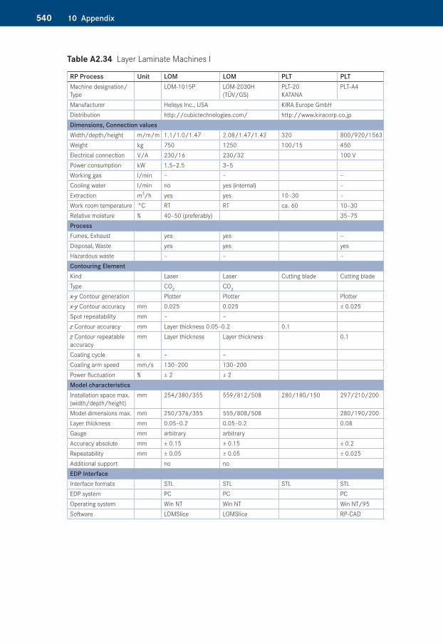
540 10 Appendix
Table A2.34�Layer Laminate Machines I
RP Process Unit LOM LOM PLT PLTMachine designation/Type
LOM-1015P LOM-2030H (TÜV/GS)
PLT-20 KATANA
PLT-A4
Manufacturer Helisys Inc., USA KIRA Europe GmbHDistribution http://cubictechnologies.com/ http://www.kiracorp.co.jpDimensions, Connection valuesWidth/depth/height m/m/m 1.1/1.0/1.47 2.08/1.47/1.42 320 800/920/1563Weight kg 750 1250 100/15 450Electrical connection V/A 230/16 230/32 100 VPower consumption kW 1.5–2.5 3–5Working gas l/min – – –Cooling water l/min no yes (internal) –Extraction m3/h yes yes 10–30 –Work room temperature °C RT RT ca. 60 10–30Relative moisture % 40–50 (preferably) 35–75ProcessFumes, Exhaust yes yes –Disposal, Waste yes yes yesHazardous waste – – –Contouring ElementKind Laser Laser Cutting blade Cutting bladeType CO2 CO2
x-y Contour generation Plotter Plotter Plotterx-y Contour accuracy mm 0.025 0.025 ± 0.025Spot repeatability mm – –z Contour accuracy mm Layer thickness 0.05–0.2 0.1z Contour repeatable accuracy
mm Layer thickness Layer thickness 0.1
Coating cycle s – –Coating arm speed mm/s 130–200 130–200Power fluctuation % ± 2 ± 2Model characteristicsInstallation space max. (width/depth/height)
mm 254/380/355 559/812/508 280/180/150 297/210/200
Model dimensions max. mm 250/376/355 555/808/508 280/190/200Layer thickness mm 0.05–0.2 0.05–0.2 0.08Gauge mm arbitrary arbitrary Accuracy absolute mm ± 0.15 ± 0.15 ± 0.2Repeatability mm ± 0.05 ± 0.05 ± 0.025Additional support no noEDP InterfaceInterface formats STL STL STL STLEDP system PC PC PCOperating system Win NT Win NT Win NT/95Software LOMSlice LOMSlice RP-CAD
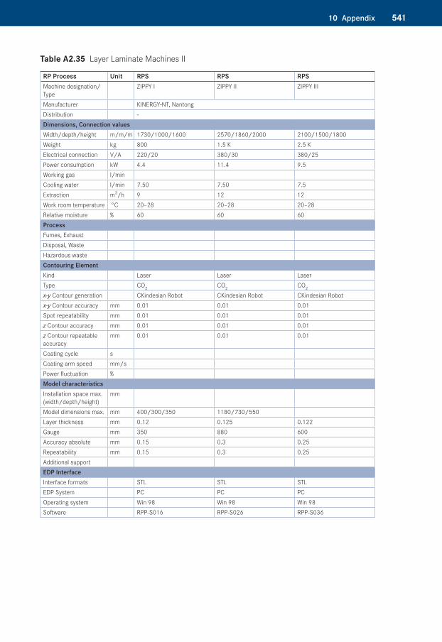
54110 Appendix
Table A2.35�Layer Laminate Machines II
RP Process Unit RPS RPS RPSMachine designation/Type
ZIPPY I ZIPPY II ZIPPY III
Manufacturer KINERGY-NT, NantongDistribution -Dimensions, Connection valuesWidth/depth/height m/m/m 1730/1000/1600 2570/1860/2000 2100/1500/1800Weight kg 800 1.5 K 2.5 KElectrical connection V/A 220/20 380/30 380/25Power consumption kW 4.4 11.4 9.5Working gas l/minCooling water l/min 7.50 7.50 7.5Extraction m3/h 9 12 12Work room temperature °C 20–28 20–28 20–28Relative moisture % 60 60 60ProcessFumes, ExhaustDisposal, WasteHazardous wasteContouring ElementKind Laser Laser LaserType CO2 CO2 CO2
x-y Contour generation CKindesian Robot CKindesian Robot CKindesian Robotx-y Contour accuracy mm 0.01 0.01 0.01Spot repeatability mm 0.01 0.01 0.01z Contour accuracy mm 0.01 0.01 0.01z Contour repeatable accuracy
mm 0.01 0.01 0.01
Coating cycle sCoating arm speed mm/sPower fluctuation %Model characteristicsInstallation space max. (width/depth/height)
mm
Model dimensions max. mm 400/300/350 1180/730/550Layer thickness mm 0.12 0.125 0.122Gauge mm 350 880 600Accuracy absolute mm 0.15 0.3 0.25Repeatability mm 0.15 0.3 0.25Additional supportEDP InterfaceInterface formats STL STL STLEDP System PC PC PCOperating system Win 98 Win 98 Win 98Software RPP-S016 RPP-S026 RPP-S036
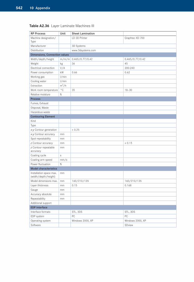
542 10 Appendix
Table A2.36�Layer Laminate Machines III
RP Process Unit Sheet LaminationMachine designation/Type
LD 3D Printer Graphtec XD 700
Manufacturer 3D SystemsDistribution www.3dsystems.comDimensions, Connection valuesWidth/depth/height m/m/m 0.465/0.77/0.42 0.465/0.77/0.42Weight kg 36 45Electrical connection V/A 200-240Power consumption kW 0.66 0.62Working gas l/minCooling water l/minExtraction m3/hWork room temperature °C 35 18–30Relative moisture %ProcessFumes, ExhaustDisposal, WasteHazardous wasteContouring ElementKindTypex-y Contour generation ± 0.25x-y Contour accuracy mmSpot repeatability mmz Contour accuracy mm ± 0.15z Contour repeatable accuracy
mm
Coating cycle sCoating arm speed mm/sPower fluctuation %Model characteristicsInstallation space max. (width/depth/height)
mm
Model dimensions max. mm 160/210/135 160/210/135Layer thickness mm 0.15 0.168Gauge mmAccuracy absolute mmRepeatability mmAdditional supportEDP InterfaceInterface formats STL, 3DS STL, 3DSEDP system PC PCOperating system Windows 2000, XP Windows 2000, XP Software SDview
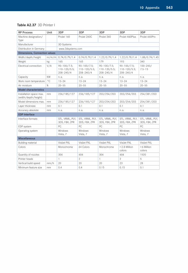
54310 Appendix
Table A2.37�3D Printer I
RP Process Unit 3DP 3DP 3DP 3DP 3DPMachine designation/Type
ProJet 160 ProJet 260C ProJet 360 ProJet 460Plus ProJet 660Pro
Manufacturer 3D Systems Distribution in Germany www.3dsystems.comDimensions, Connection valuesWidth/depth/height m/m/m 0.74/0.79/1.4 0.74/0.79/1.4 1.22/0.79/1.4 1.22/0.79/1.4 1.88/0.74/1.45Weight kg 165 165 179 193 340Electrical connection V/A 90–100/7.5;
110–120/5.5; 208–240/4
90–100/7.5; 110–120/5.5; 208–240/4
90–100/7.5; 110–120/5.5; 208–240/4
90–100/7.5; 110–120/5.5; 208–240/4
100–240/ 7.5–15
Capacity KW n. a. n. a. n. a. n. a. n. a.Work room temperature °C 13–24 13–24 13–24 13–24 13–24Air moisture % 20–55 20–55 20–55 20–55 20–55Model characteristicsInstallation space max. (width/depth/height)
mm 236/185/127 236/185/127 203/254/203 203/254/203 254/381/203
Model dimensions max. mm 236/185/127 236/185/127 203/254/203 203/254/203 254/381/203Layer thickness mm 0.1 0.1 0.1 0.1 0.1Accuracy absolute mm n. a. n. a. n. a. n. a. n. a.EDP InterfaceInterface formats STL, VRML, PLY,
3DS, FBX, ZPRSTL, VRML, PLY, 3DS, FBX, ZPR
STL, VRML, PLY, 3DS, FBX, ZPR
STL, VRML, PLY, 3DS, FBX, ZPR
STL, VRML, PLY, 3DS, FBX, ZPR
EDP system PC PC PC PC PCOperating system Windows
Vista, 7Windows Vista, 7
Windows Vista, 7
Windows Vista, 7
Windows Vista, 7
MiscellaneousBuilding material VisiJet PXL VisiJet PXL VisiJet PXL VisiJet PXL VisiJet PXLColors Monochrome 64 Colors Monochrome > 2.8 Million
colors> 6 Million colors
Quantity of nozzles 304 604 304 604 1520Printer heads 1 2 1 2 5Vertical build speed mm/h 20 20 20 23 28Minimum feature size mm 0.4 0.4 0.15 0.15 0.1
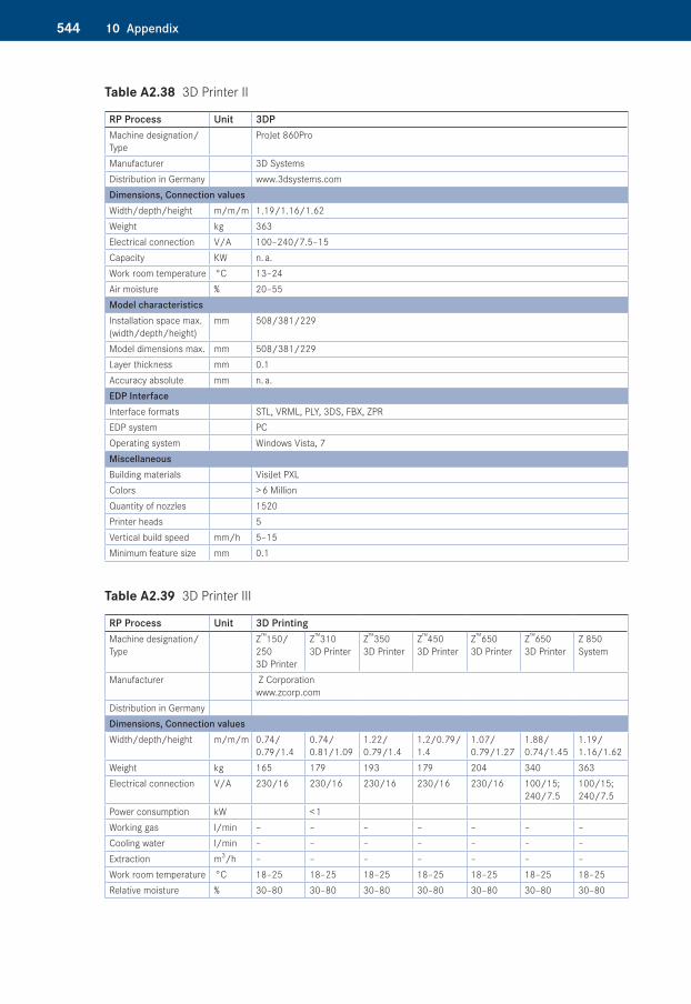
544 10 Appendix
Table A2.38�3D Printer II
RP Process Unit 3DPMachine designation/Type
ProJet 860Pro
Manufacturer 3D Systems Distribution in Germany www.3dsystems.comDimensions, Connection valuesWidth/depth/height m/m/m 1.19/1.16/1.62Weight kg 363Electrical connection V/A 100–240/7.5–15Capacity KW n. a.Work room temperature °C 13–24Air moisture % 20–55Model characteristicsInstallation space max. (width/depth/height)
mm 508/381/229
Model dimensions max. mm 508/381/229Layer thickness mm 0.1Accuracy absolute mm n. a.EDP InterfaceInterface formats STL, VRML, PLY, 3DS, FBX, ZPREDP system PCOperating system Windows Vista, 7MiscellaneousBuilding materials VisiJet PXLColors > 6 MillionQuantity of nozzles 1520Printer heads 5Vertical build speed mm/h 5–15Minimum feature size mm 0.1
Table A2.39�3D Printer III
RP Process Unit 3D PrintingMachine designation/Type
Z™150/ 250 3D Printer
Z™310 3D Printer
Z™350 3D Printer
Z™450 3D Printer
Z™650 3D Printer
Z™650 3D Printer
Z 850 System
Manufacturer Z Corporation www.zcorp.com
Distribution in GermanyDimensions, Connection valuesWidth/depth/height m/m/m 0.74/
0.79/1.40.74/ 0.81/1.09
1.22/ 0.79/1.4
1.2/0.79/ 1.4
1.07/ 0.79/1.27
1.88/ 0.74/1.45
1.19/ 1.16/1.62
Weight kg 165 179 193 179 204 340 363Electrical connection V/A 230/16 230/16 230/16 230/16 230/16 100/15;
240/7.5100/15; 240/7.5
Power consumption kW < 1Working gas l/min – – – – – – –Cooling water l/min – – – – – – –Extraction m3/h – – – – – – –Work room temperature °C 18–25 18–25 18–25 18–25 18–25 18–25 18–25Relative moisture % 30–80 30–80 30–80 30–80 30–80 30–80 30–80
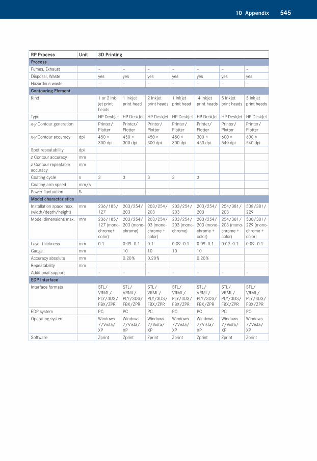
54510 Appendix
RP Process Unit 3D PrintingProcessFumes, Exhaust – – – – – – –Disposal, Waste yes yes yes yes yes yes yesHazardous waste – – – – – – –Contouring ElementKind 1 or 2 Ink-
jet print heads
1 Inkjet print head
2 Inkjet print heads
1 Inkjet print head
4 Inkjet print heads
5 Inkjet print heads
5 Inkjet print heads
Type HP DeskJet HP DeskJet HP DeskJet HP DeskJet HP DeskJet HP DeskJet HP DeskJetx-y Contour generation Printer/
PlotterPrinter/Plotter
Printer/Plotter
Printer/Plotter
Printer/Plotter
Printer/Plotter
Printer/Plotter
x-y Contour accuracy dpi 450 × 300 dpi
450 × 300 dpi
450 × 300 dpi
450 × 300 dpi
300 × 450 dpi
600 × 540 dpi
600 × 540 dpi
Spot repeatability dpiz Contour accuracy mmz Contour repeatable accuracy
mm
Coating cycle s 3 3 3 3 3Coating arm speed mm/sPower fluctuation % – – – – – – –Model characteristicsInstallation space max. (width/depth/height)
mm 236/185/ 127
203/254/ 203
203/254/ 203
203/254/ 203
203/254/ 203
254/381/ 203
508/381/ 229
Model dimensions max. mm 236/185/ 127 (mono-chrome+ color)
203/254/ 203 (mono-chrome)
203/254/ 03 (mono-chrome + color)
203/254/ 203 (mono-chrome)
203/254/ 203 (mono-chrome + color)
254/381/ 203 (mono-chrome + color)
508/381/ 229 (mono-chrome + color)
Layer thickness mm 0.1 0.09–0.1 0.1 0.09–0.1 0.09–0.1 0.09–0.1 0.09–0.1Gauge mm 10 10 10 10Accuracy absolute mm 0.20 % 0.20 % 0.20 %Repeatability mmAdditional support – – – – – – –EDP InterfaceInterface formats STL/
VRML/PLY/3DS/FBX/ZPR
STL/VRML/PLY/3DS/FBX/ZPR
STL/VRML/PLY/3DS/FBX/ZPR
STL/VRML/PLY/3DS/FBX/ZPR
STL/VRML/PLY/3DS/FBX/ZPR
STL/VRML/PLY/3DS/FBX/ZPR
STL/VRML/PLY/3DS/FBX/ZPR
EDP system PC PC PC PC PC PC PCOperating system Windows
7/Vista/XP
Windows 7/Vista/XP
Windows 7/Vista/XP
Windows 7/Vista/XP
Windows 7/Vista/XP
Windows 7/Vista/XP
Windows 7/Vista/XP
Software Zprint Zprint Zprint Zprint Zprint Zprint Zprint
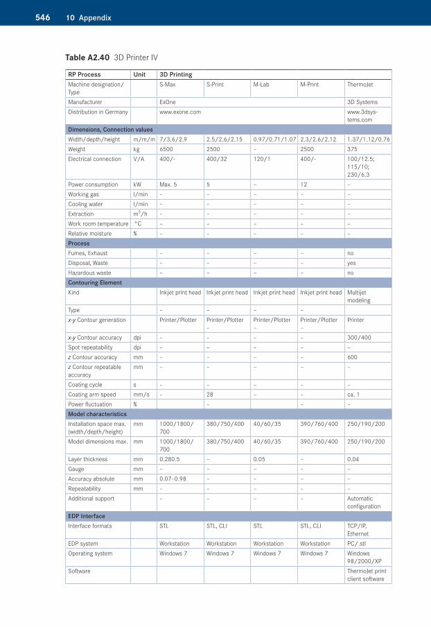
546 10 Appendix
Table A2.40�3D Printer IV
RP Process Unit 3D Printing Machine designation/Type
S-Max S-Print M-Lab M-Print ThermoJet
Manufacturer ExOne 3D Systems Distribution in Germany www.exone.com www.3dsys-
tems.comDimensions, Connection valuesWidth/depth/height m/m/m 7/3.6/2.9 2.5/2.6/2.15 0.97/0.71/1.07 2.3/2.6/2.12 1.37/1.12/0.76Weight kg 6500 2500 – 2500 375Electrical connection V/A 400/- 400/32 120/1 400/- 100/12.5;
115/10; 230/6.3
Power consumption kW Max. 5 5 – 12 –Working gas l/min – – – – –Cooling water l/min – – – – –Extraction m3/h – – – – –Work room temperature °C – – – – –Relative moisture % – – – – –ProcessFumes, Exhaust – – – – noDisposal, Waste – – – – yesHazardous waste – – – – noContouring ElementKind Inkjet print head Inkjet print head Inkjet print head Inkjet print head Multijet
modelingType – – – –x-y Contour generation Printer/Plotter Printer/Plotter
–Printer/Plotter –
Printer/Plotter –
Printer
x-y Contour accuracy dpi – – – – 300/400Spot repeatability dpi – – – – –z Contour accuracy mm – – – – 600z Contour repeatable accuracy
mm – – – – –
Coating cycle s – – – – –Coating arm speed mm/s – 28 – – ca. 1Power fluctuation % – – –Model characteristicsInstallation space max. (width/depth/height)
mm 1000/1800/ 700
380/750/400 40/60/35 390/760/400 250/190/200
Model dimensions max. mm 1000/1800/ 700
380/750/400 40/60/35 390/760/400 250/190/200
Layer thickness mm 0.280.5 – 0.05 – 0.04Gauge mm – – – – –Accuracy absolute mm 0.07–0.98 – – – –Repeatability mm – – – – –Additional support – – – – Automatic
configurationEDP InterfaceInterface formats STL STL, CLI STL STL, CLI TCP/IP,
EthernetEDP system Workstation Workstation Workstation Workstation PC/.stlOperating system Windows 7 Windows 7 Windows 7 Windows 7 Windows
98/2000/XPSoftware ThermoJet print
client software
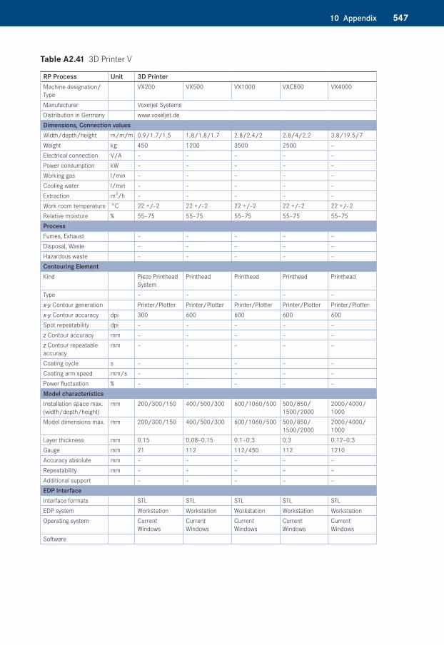
54710 Appendix
Table A2.41�3D Printer V
RP Process Unit 3D PrinterMachine designation/Type
VX200 VX500 VX1000 VXC800 VX4000
Manufacturer Voxeljet SystemsDistribution in Germany www.voxeljet.deDimensions, Connection valuesWidth/depth/height m/m/m 0.9/1.7/1.5 1.8/1.8/1.7 2.8/2.4/2 2.8/4/2.2 3.8/19.5/7Weight kg 450 1200 3500 2500 –Electrical connection V/A – – – – –Power consumption kW – – – – –Working gas l/min – – – – –Cooling water l/min – – – – –Extraction m3/h – – – – –Work room temperature °C 22 +/- 2 22 +/- 2 22 +/- 2 22 +/- 2 22 +/- 2Relative moisture % 55–75 55–75 55–75 55–75 55–75ProcessFumes, Exhaust – – – – –Disposal, Waste – – – – –Hazardous waste – – – – –Contouring ElementKind Piezo Printhead
SystemPrinthead Printhead Printhead Printhead
Type – – – – –x-y Contour generation Printer/Plotter Printer/Plotter Printer/Plotter Printer/Plotter Printer/Plotter x-y Contour accuracy dpi 300 600 600 600 600Spot repeatability dpi – – – – –z Contour accuracy mm – – – – –z Contour repeatable accuracy
mm – – – – –
Coating cycle s – – – – –Coating arm speed mm/s – – – – –Power fluctuation % – – – – –Model characteristicsInstallation space max. (width/depth/height)
mm 200/300/150 400/500/300 600/1060/500 500/850/ 1500/2000
2000/4000/ 1000
Model dimensions max. mm 200/300/150 400/500/300 600/1060/500 500/850/ 1500/2000
2000/4000/ 1000
Layer thickness mm 0.15 0.08–0.15 0.1–0.3 0.3 0.12–0.3Gauge mm 21 112 112/450 112 1210Accuracy absolute mm – – – – –Repeatability mm – – – – –Additional support – – – – –EDP InterfaceInterface formats STL STL STL STL STLEDP system Workstation Workstation Workstation Workstation WorkstationOperating system Current
WindowsCurrent Windows
Current Windows
Current Windows
Current Windows
Software

548 10 Appendix
Materials for Additive Manufacturing Processes and Casting ResinsThe materials described in the following represent only a selection of the available materials. Because in this field there are frequent new and further developments, at this point, one must refer to the manufacturer.

54910 Appendix
Tabl
e A3
.1�St
ereo
litho
grap
hy M
ater
ials
I
Prop
ertie
sUn
it3D
Sys
tem
s Ac
cura
Bl
uest
one
3D S
yste
ms
Accu
Gen
3D S
yste
ms
Acur
a 50
Vant
ico
Rhen
Shap
e SL
7580
Vant
ico
Rhen
Shap
e SL
7565
DSM
Som
os
Prot
oToo
l 20
L
DSM
Som
os
Nano
Form
15
120
DSM
Som
os
Wat
erSh
ed
1112
0
DSM
Som
os
Som
os
9120
Type
Phot
opol
ymer
Phot
opol
ymer
Phot
opol
ymer
Phot
opol
ymer
Phot
opol
ymer
Phot
opol
ymer
UV
afte
rcur
ePh
otop
olym
er
UV +
ther
mal
aft
ercu
re
Phot
opol
ymer
Phot
opol
ymer
Colo
rOp
aque
blu
eTr
anslu
cent
am
ber
Ambe
r-whi
te/
gray
Whi
teTr
ansp
aren
t am
ber
Gray
Gray
Tran
spar
ent
gree
nTr
anslu
cent
am
ber
E-M
odul
us/T
ensil
e m
odul
us/
Youn
g’s
mod
ulus
MPa
7600
–117
0022
8024
80–2
690
2300
2000
–250
010
100–
1120
059
0026
50–2
880
1227
–146
2
Brea
king
elo
ngat
ion
%1.
4–2.
415
5.3–
1511
> 20
1.2–
1.3
1.2
11–2
015
–25
Flex
ural
mod
ulus
MPa
8300
–980
017
2022
10–2
340
2400
1900
–210
092
40–9
600
4450
2040
–237
013
10–1
455
Flex
ural
stre
ngth
MPa
124–
154
6372
–77
8360
–66
118–
123
129
63–7
441
–48
Char
py im
pact
stre
ngth
kJ/m
2
Char
py n
otch
impa
ct s
treng
thkJ
/m2
13–1
725
16.5
–28.
134
27–3
848
–53
Tens
ile s
treng
thM
Pa66
–68
5048
–50
5346
–54
72–7
953
47–5
430
–32
Hard
ness
at 2
3 °C
Shor
e A
9282
8684
8480
–82
Resid
ual a
sh%
Mel
ting
poin
t°C
Heat
resis
tanc
e
■ a
t 0.4
5 M
Pa°C
269
257–
259
45.9
–54.
552
–61
■ a
t 1.8
4 M
pa°C
66n.
a.43
–46
5211
583
–94
49–4
9.70
n. a.
Glas
s tra
nsiti
on te
mpe
ratu
re°C
65–6
6n.
a.49
–53
6348
–52
4980
39–5
6n.
a.
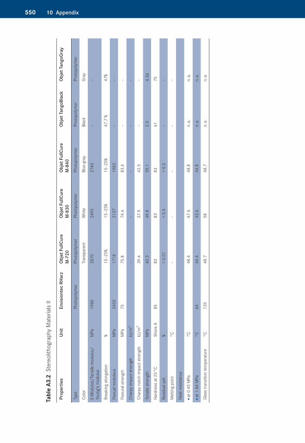
550 10 Appendix
Tabl
e A3
.2�S
tere
olith
ogra
phy
Mat
eria
ls II
Prop
ertie
sUn
itEn
visi
onte
c RH
arz
Obje
t Ful
lCur
e M
720
Obje
t Ful
lCur
e M
830
Obje
t Ful
lCur
e M
840
Obje
t Tan
goBl
ack
Obje
t Tan
goGr
ay
Type
Phot
opol
ymer
Phot
opol
ymer
Phot
opol
ymer
Phot
opol
ymer
Phot
opol
ymer
Phot
opol
ymer
Colo
rTr
ansp
aren
tW
hite
Blue
-gra
yBl
ack
Gray
E-M
odul
us/T
ensil
e m
odul
us/
Youn
g’s
mod
ulus
MPa
1980
2870
2495
2740
––
Brea
king
elo
ngat
ion
%15
–25%
15–2
5%15
–25%
47.7
%47
%
Flex
ual m
odul
eus
MPa
2450
1718
2137
1983
––
Flex
ural
stre
ngth
MPa
7575
.874
.683
.6–
–
Char
py im
pact
stre
ngth
kJ/m
2–
––
––
Char
py n
otch
impa
ct s
treng
thkJ
/m2
39.6
37.5
42.5
––
Tens
ile s
treng
thM
Pa60
.349
.855
.12.
04.
36
Hard
ness
at 2
3 °C
Shor
e A
8583
8383
6175
Resid
ual a
sh%
< 0.
01<
0.4
< 0.
3–
–
Mel
ting
poin
t°C
––
––
–
Heat
resis
tanc
e
■ a
t 0.4
5 M
Pa°C
48.4
47.6
48.8
n. a.
n. a.
■ a
t 1.8
4 M
Pa°C
6444
.443
.644
.8n.
a.n.
a.
Glas
s tra
nsiti
on te
mpe
ratu
re°C
135
48.7
5848
.7n.
a.n.
a.
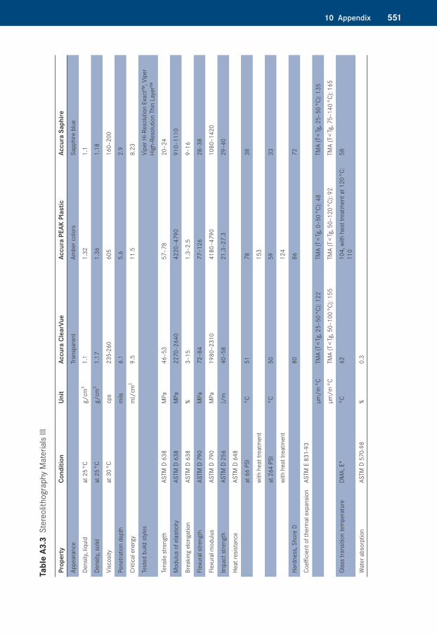
55110 Appendix
Tabl
e A3
.3�S
tere
olith
ogra
phy
Mat
eria
ls III
Prop
erty
Cond
ition
Unit
Accu
ra C
lear
Vue
Accu
ra P
EAK
Plas
ticAc
cura
Sap
hire
Appe
aran
ceTr
ansp
aren
tAm
ber c
olor
sSa
pphi
re b
lue
Dens
ity, l
iqui
dat
25
°Cg/
cm3
1.1
1.32
1.1
Dens
ity, s
olid
at 2
5 °C
g/cm
31.
171.
361.
18
Visc
osity
at 3
0 °C
cps
235-
260
605
160–
200
Pene
tratio
n de
pth
mils
6.1
5.6
2.9
Criti
cal e
nerg
ym
J/cm
29.
511
.58.
23
Test
ed b
uild
sty
les
Vipe
r Hi-R
esol
utio
n Ex
act™
, Vip
er
High
-Res
olut
ion
Thin
Lay
er™
Tens
ile s
treng
thAS
TM D
638
MPa
46–5
357
–78
20–2
4
Mod
ulus
of e
last
icity
ASTM
D 6
38M
Pa22
70–2
640
4220
–479
091
0–11
10
Brea
king
elo
ngat
ion
ASTM
D 6
38%
3–15
1.3–
2.5
9–16
Flex
ural
stre
ngth
ASTM
D 7
90M
Pa72
–84
77–1
2628
–38
Flex
ural
mod
ulus
ASTM
D 7
90M
Pa19
80–2
310
4180
–479
010
80–1
420
Impa
ct s
treng
thAS
TM D
256
J/m
40–5
821
.3–2
7.3
29–4
0
Heat
resis
tanc
eAS
TM D
648
at 6
6 PS
I°C
5178
38
with
hea
t tre
atm
ent
15
3
at 2
64 P
SI°C
5059
33
with
hea
t tre
atm
ent
124
Hard
ness
, Sho
re D
80
8672
Coeffi
cien
t of t
herm
al e
xpan
sion
ASTM
E 8
31-9
3
µm/m
°CTM
A (T
< Tg
, 25–
50 °C
): 12
2TM
A (T
< Tg
, 0–5
0 °C
): 48
TMA
(T <
Tg, 2
5–50
°C):
135
µm/m
°CTM
A (T
< Tg
, 50–
100
°C):
155
TMA
(T <
Tg, 5
0–12
0 °C
): 92
TMA
(T <
Tg, 7
5–14
0 °C
): 16
5
Glas
s tra
nsiti
on te
mpe
ratu
reDM
A, E
"°C
6210
4, w
ith h
eat t
reat
men
t at 1
20 °C
: 11
058
Wat
er a
bsor
ptio
nAS
TM D
570
-98
%0.
3
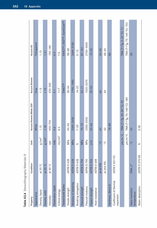
552 10 Appendix
Tabl
e A3
.4�S
tere
olith
ogra
phy
Mat
eria
ls IV
Prop
erty
Cond
ition
Unit
Accu
ra X
trem
e W
hite
200
Accu
ra X
trem
eAc
cura
60
Appe
aran
ceW
hite
Gray
Tran
spar
ent
Dens
ity, l
iqui
dat
25
°Cg/
cm3
1.12
1.13
1.13
Dens
ity, s
olid
at 2
5 °C
g/cm
31.
181.
191.
21Vi
scos
ityat
30
°Ccp
s65
0–75
025
0–30
015
0–18
0Pe
netra
tion
dept
hm
ils4.
64.
16.
3Cr
itica
l ene
rgy
mJ/
cm2
8.3
11.7
7.6
Test
ed b
uild
Sty
les
EXAC
T™EX
ACT™
, FAS
T™, Q
uick
Cast
™Te
nsile
stre
ngth
ASTM
D 6
38M
Pa45
–50
38–4
458
–68
Mod
ulus
of e
last
icity
ASTM
D 6
38M
Pa23
00–2
630
1790
–198
026
90–3
100
Brea
king
elo
ngat
ion
ASTM
D 6
38%
7–20
14–2
25–
13Fl
exur
al s
treng
thAS
TM D
790
MPa
75–7
952
–71
87–1
01Fl
exur
al m
odul
usAS
TM D
790
MPa
2350
–255
015
20–2
070
2700
–300
0Im
pact
stre
ngth
ASTM
D 2
56J/
m55
–66
35–5
215
–25
Heat
resi
stan
ceAS
TM D
648
at 6
6 PS
I °C
4762
53–5
5at
264
PSI
°C42
5448
–50
Hard
ness
, Sho
re D
78–8
086
Coeffi
cien
t of t
herm
al
expa
nsio
nAS
TM E
831
-93
µm/m
°CTM
A (T
< Tg
, 30–
50 °C
): 95
TMA
(T <
Tg, 0
–20
°C):
71µm
/m °C
TMA
(T <
Tg, 7
0–14
0 °C
): 18
0TM
A (T
< Tg
, 75–
140
°C):
153
Glas
s tra
nsiti
on
tem
pera
ture
DMA,
E"
°C52
58
Wat
er a
bsor
ptio
nAS
TM D
570
-98
%0.
38
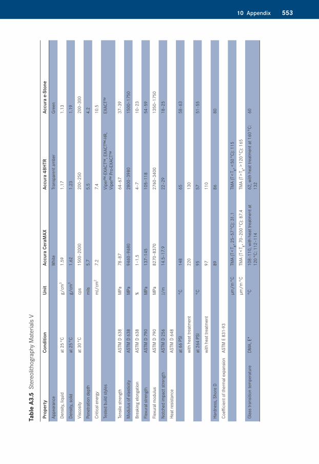
55310 Appendix
Tabl
e A3
.5�S
tere
olith
ogra
phy
Mat
eria
ls V
Prop
erty
Cond
ition
Unit
Accu
ra C
eraM
AXAc
cura
48H
TRAc
cura
eS
tone
Appe
aran
ceW
hite
Tran
spar
ent a
mbe
rGr
een
Dens
ity, l
iqui
dat
25
°Cg/
cm3
1.59
1.17
1.13
Dens
ity, s
olid
at 2
5 °C
g/cm
31.
621.
231.
19
Visc
osity
at 3
0 °C
cps
1500
–200
020
0–25
020
0–30
0
Pene
tratio
n de
pth
mils
5.7
5.5
4.2
Criti
cal e
nerg
ym
J/cm
27.
27.
410
.5
Test
ed b
uild
sty
les
Vipe
r™-E
XACT
™, E
XACT
™-H
R,
Vipe
r™ P
ro-E
XACT
™EX
ACT™
Tens
ile s
treng
thAS
TM D
638
MPa
78–8
764
–67
37–3
9
Mod
ulus
of e
last
icity
ASTM
D 6
38M
Pa94
60–9
680
2800
–398
015
00–1
750
Brea
king
elo
ngat
ion
ASTM
D 6
38%
1–1.
54–
710
–23
Flex
ural
stre
ngth
ASTM
D 7
90M
Pa13
7–14
510
5–11
854
–59
Flex
ural
mod
ulus
ASTM
D 7
90M
Pa82
70–8
370
2760
–340
013
50–1
750
Notc
hed
impa
ct s
treng
thAS
TM D
256
J/m
14.5
–17.
922
–29
18–2
5
Heat
resis
tanc
eAS
TM D
648
at 6
6 PS
I°C
148
6558
–63
with
hea
t tre
atm
ent
220
130
at 2
64 P
SI°C
9557
51–5
5
wi
th h
eat t
reat
men
t97
110
Hard
ness
, Sho
re D
8986
80
Coeffi
cien
t of t
herm
al e
xpan
sion
ASTM
E 8
31-9
3
µm/m
°CTM
A (T
< T g , 2
5–57
°C):
31.1
TMA
(T <
T g , < 5
0 °C
): 11
5
µm/m
°CTM
A (T
< T g , 7
0–20
0 °C
): 87
.4TM
A (T
> T g , >
120
°C):
165
Glas
s tra
nsiti
on te
mpe
ratu
reDM
A, E
"°C
108–
110,
with
hea
t tre
atm
ent a
t 12
0 °C
: 112
–114
62, w
ith h
eat t
reat
men
t at 1
60 °C
: 13
260
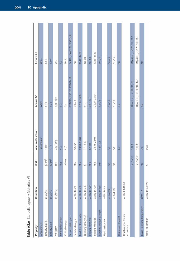
554 10 Appendix
Tabl
e A3
.6�S
tere
olith
ogra
phy
Mat
eria
ls VI
Prop
erty
Cond
ition
Unit
Accu
ra C
astP
roAc
cura
55
Accu
ra 2
5
Appe
aran
ce
Tr
ansp
aren
tW
hite
Whi
te
Dens
ity, l
iqui
dat
25
°Cg/
cm3
1.08
1.13
1.14
Dens
ity, s
olid
at 2
5 °C
g/cm
31.
171.
201.
19
Visc
osity
at 3
0 °C
cps
240–
260
155–
185
250
Pene
tratio
n de
pth
mils
6.2
5.2
4.2
Criti
cal e
nerg
ym
J/cm
28.
77.
410
.5
Test
ed b
uild
sty
les
EX
ACT™
, FAS
T™; E
XACT
-HR
FAST
™, E
XACT
™, E
XACT
-HR
Tens
ile s
treng
thAS
TM D
638
MPa
52–5
363
–68
38
Mod
ulus
of e
last
icity
ASTM
D 6
38M
Pa24
90–2
620
3200
–338
015
90–1
660
Brea
king
elo
ngat
ion
ASTM
D 6
38%
4.1–
8.3
5–8
13–2
0
Flex
ural
stre
ngth
ASTM
D 7
90M
Pa82
–84
88–1
1055
–58
Flex
ural
mod
ulus
ASTM
D 7
90M
Pa23
10–2
340
2690
–324
013
80–1
660
Notc
hed
impa
ct s
treng
thAS
TM D
256
J/m
43–4
9.5
12–2
219
–24
Heat
resis
tanc
eAS
TM D
648
at 6
6 PS
I°C
5155
–58
58–6
3
at 2
64 P
SI°C
5051
–53
51–5
5
Hard
ness
, Sho
re D
8585
80
Coeffi
cien
t of t
herm
al
expa
nsio
nAS
TM E
831
-93
µm/m
°C10
2.9
TMA
(T >
T g , >12
0 °C
): 61
TMA
(T >
T g , >12
0 °C
): 10
7
µm/m
°C16
0.2
TMA
(T >
T g , >12
0 °C
): 16
3TM
A (T
> T g , >
120
°C):
151
Glas
s tra
nsiti
on te
mpe
ratu
reDM
A, E
"°C
7056
60
Wat
er a
bsor
ptio
nAS
TM D
570
-98
%0.
33
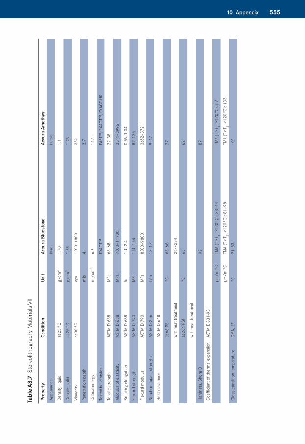
55510 Appendix
Tabl
e A3
.7�S
tere
olith
ogra
phy
Mat
eria
ls VI
I
Prop
erty
Cond
ition
Unit
Accu
ra B
lues
tone
Accu
ra A
met
hyst
Appe
aran
ceBl
uePu
rple
Dens
ity, l
iqui
dat
25
°Cg/
cm3
1.70
1.1
Dens
ity, s
olid
at 2
5 °C
g/cm
31.
781.
23
Visc
osity
at 3
0 °C
cps
1200
–180
035
0
Pene
tratio
n de
pth
mils
4.1
3.7
Criti
cal e
nerg
ym
J/cm
26.
914
.4
Test
ed b
uild
sty
les
EXAC
T™FA
ST™
, EXA
CT™
, EXA
CT-H
R
Tens
ile s
treng
thAS
TM D
638
MPa
66–6
822
–38
Mod
ulus
of e
last
icity
ASTM
D 6
38M
Pa76
00–1
1700
3514
–399
6
Brea
king
elo
ngat
ion
ASTM
D 6
38%
1.4–
2.4
0.56
–1.0
4
Flex
ural
stre
ngth
ASTM
D 7
90M
Pa12
4–15
487
–125
Flex
ural
mod
ulus
ASTM
D 7
90M
Pa83
00–9
800
3652
–372
1
Notc
hed
impa
ct s
treng
thAS
TM D
256
J/m
13–1
79–
12
Heat
resis
tanc
eAS
TM D
648
at 6
6 PS
I°C
65–6
677
with
hea
t tre
atm
ent
267–
284
at 2
64 P
SI°C
6562
with
hea
t tre
atm
ent
Hard
ness
, Sho
re D
9287
Coeffi
cien
t of t
herm
al e
xpan
sion
ASTM
E 8
31-9
3
µm/m
°CTM
A (T
> T g , >
120
°C):
33–4
4TM
A (T
> T g , >
120
°C):
57
µm/m
°CTM
A (T
> T g , >
120
°C):
81–9
8TM
A (T
> T g , >
120
°C):
133
Glas
s tra
nsiti
on te
mpe
ratu
reDM
A, E
"°C
71–8
310
3

556 10 Appendix
Tabl
e A3
.8�S
tere
olith
ogra
phy
Mat
eria
ls VI
II
Prop
erty
Cond
ition
Unit
RenS
hape
SL7
800
RenS
hape
SL7
810
Appe
aran
ceW
hite
Dens
ity, l
iqui
dat
25
°Cg/
cm3
1.12
1.13
Dens
ity, s
olid
at 2
5 °C
g/cm
31.
151.
16
Visc
osity
at 3
0 °C
cps
205
210
Pene
tratio
n de
pth
mils
5.6
on S
LA 7
000/
5000
5.74
auf S
LA 5
00/3
500/
Vips
er
Si2 S
yste
m5.
67
Criti
cal e
nerg
ym
J/cm
29.
9
auf S
LA 7
000/
5000
9.98
auf S
LA 5
00/3
500/
Vips
er
Si2 S
yste
m9.
51
90 m
inut
e +
UV p
ostc
ure
90 m
inut
e UV
+ 2
h a
t 80
°C th
erm
al tr
eatm
ent
90 m
inut
e UV
pos
tcur
e90
min
ute
UV +
2 h
at
80 °C
ther
mal
trea
tmen
t
Tens
ile s
treng
thAS
TM D
638
MPa
41–4
744
35–5
139
–51
Mod
ulus
of e
last
icity
ASTM
D 6
38M
Pa20
75–2
400
2180
–225
017
93–2
400
2000
–240
0
Brea
king
elo
ngat
ion
ASTM
D 6
38%
10–1
810
–15
10–2
010
–14
Flex
ural
stre
ngth
ASTM
D 7
90M
Pa69
–74
72–7
458
–69
62–6
9
Flex
ural
mod
ulus
ASTM
D 7
90M
Pa22
80–2
650
2380
–264
018
96–2
400
2096
–240
0
Notc
hed
impa
ct s
treng
thAS
TM D
256
J/m
37–5
837
–48
44–4
944
–50
Heat
resis
tanc
eAS
TM D
648
at 6
6 PS
I°C
6262
5150
Hard
ness
, Sho
re D
8787
8687
Coeffi
cien
t of t
herm
al e
xpan
sion
ASTM
E 8
31-9
3
µm/m
°C10
010
996
99
µm/m
°C
Glas
s tra
nsiti
on te
mpe
ratu
reDM
A, E
"°C
5759
6262
Wat
er a
bsor
ptio
nAS
TM D
570
-98
%
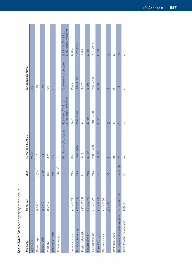
55710 Appendix
Tabl
e A3
.8�S
tere
olith
ogra
phy
Mat
eria
ls VI
II
Prop
erty
Cond
ition
Unit
RenS
hape
SL7
800
RenS
hape
SL7
810
Appe
aran
ceW
hite
Dens
ity, l
iqui
dat
25
°Cg/
cm3
1.12
1.13
Dens
ity, s
olid
at 2
5 °C
g/cm
31.
151.
16
Visc
osity
at 3
0 °C
cps
205
210
Pene
tratio
n de
pth
mils
5.6
on S
LA 7
000/
5000
5.74
auf S
LA 5
00/3
500/
Vips
er
Si2 S
yste
m5.
67
Criti
cal e
nerg
ym
J/cm
29.
9
auf S
LA 7
000/
5000
9.98
auf S
LA 5
00/3
500/
Vips
er
Si2 S
yste
m9.
51
90 m
inut
e +
UV p
ostc
ure
90 m
inut
e UV
+ 2
h a
t 80
°C th
erm
al tr
eatm
ent
90 m
inut
e UV
pos
tcur
e90
min
ute
UV +
2 h
at
80 °C
ther
mal
trea
tmen
t
Tens
ile s
treng
thAS
TM D
638
MPa
41–4
744
35–5
139
–51
Mod
ulus
of e
last
icity
ASTM
D 6
38M
Pa20
75–2
400
2180
–225
017
93–2
400
2000
–240
0
Brea
king
elo
ngat
ion
ASTM
D 6
38%
10–1
810
–15
10–2
010
–14
Flex
ural
stre
ngth
ASTM
D 7
90M
Pa69
–74
72–7
458
–69
62–6
9
Flex
ural
mod
ulus
ASTM
D 7
90M
Pa22
80–2
650
2380
–264
018
96–2
400
2096
–240
0
Notc
hed
impa
ct s
treng
thAS
TM D
256
J/m
37–5
837
–48
44–4
944
–50
Heat
resis
tanc
eAS
TM D
648
at 6
6 PS
I°C
6262
5150
Hard
ness
, Sho
re D
8787
8687
Coeffi
cien
t of t
herm
al e
xpan
sion
ASTM
E 8
31-9
3
µm/m
°C10
010
996
99
µm/m
°C
Glas
s tra
nsiti
on te
mpe
ratu
reDM
A, E
"°C
5759
6262
Wat
er a
bsor
ptio
nAS
TM D
570
-98
%
Tabl
e A3
.9�S
tere
olith
ogra
phy
Mat
eria
ls IX
Prop
erty
Cond
ition
Unit
RenS
hape
SL7
820
RenS
hape
SL7
840
Appe
aran
ceW
hite
Clea
r
Dens
ity, l
iqui
dat
25
°Cg/
cm3
1.13
1.13
Dens
ity, s
olid
at 2
5 °C
g/cm
31.
161.
16
Visc
osity
at 3
0 °C
cps
210
320
Pene
tratio
n de
pth
mils
4.5
5
Criti
cal e
nerg
ym
J/cm
210
15
90 m
inut
e +
UV p
ost-c
ure
90 m
inut
e UV
+ 2
h a
t 80
°C th
erm
al tr
eatm
ent
90 m
inut
e +
UV p
ostc
ure
90 m
inut
e UV
+ 2
h a
t 80
°C th
erm
al tr
eatm
ent
Tens
ile s
treng
thAS
TM D
638
MPa
36–5
139
–51
36–4
537
–45
Mod
ulus
of e
last
icity
ASTM
D 6
38M
Pa19
00–2
400
2000
–250
017
00–2
200
1600
–220
0
Brea
king
elo
ngat
ion
ASTM
D 6
38%
8–18
9–14
11–1
711
–18
Flex
ural
stre
ngth
ASTM
D 7
90M
Pa59
–80
62–8
065
–80
62–8
0
Flex
ural
mod
ulus
ASTM
D 7
90M
Pa20
00–2
400
2100
–250
016
00–2
200
1600
–220
0
Impa
ct s
treng
thAS
TM D
256
J/m
42–4
830
–49
37–6
035
–60
Heat
resis
tanc
eAS
TM D
648
at 6
6 PS
I°C
5150
4846
Hard
ness
, Sho
re D
8687
8687
Coeffi
cien
t of t
herm
al e
xpan
sion
ASTM
E 8
31-9
3µm
/m °C
9393
100
110
Glas
s tra
nsiti
on te
mpe
ratu
reDM
A, E
"°C
6262
5859
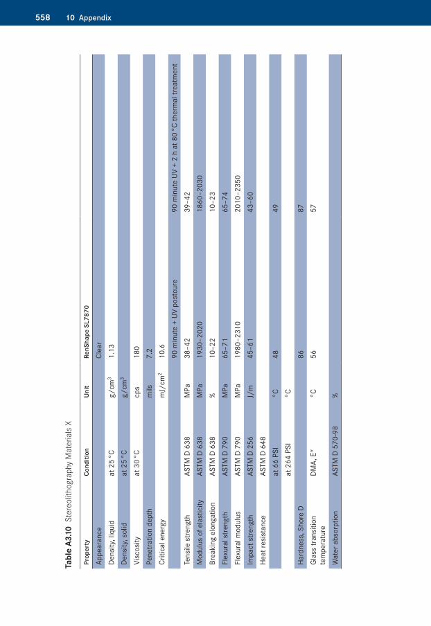
558 10 Appendix
Tabl
e A3
.10�S
tere
olith
ogra
phy
Mat
eria
ls X
Prop
erty
Cond
ition
Unit
RenS
hape
SL7
870
Appe
aran
ceCl
ear
Dens
ity, l
iqui
dat
25
°Cg/
cm3
1.13
Dens
ity, s
olid
at 2
5 °C
g/cm
3
Visc
osity
at 3
0 °C
cps
180
Pene
tratio
n de
pth
mils
7.2
Criti
cal e
nerg
ym
J/cm
210
.690
min
ute
+ UV
pos
tcur
e90
min
ute
UV +
2 h
at 8
0 °C
ther
mal
trea
tmen
tTe
nsile
stre
ngth
ASTM
D 6
38M
Pa38
–42
39–4
2M
odul
us o
f ela
stic
ityAS
TM D
638
MPa
1930
–202
018
60–2
030
Brea
king
elo
ngat
ion
ASTM
D 6
38%
10–2
210
–23
Flex
ural
stre
ngth
ASTM
D 7
90M
Pa65
–71
65–7
4Fl
exur
al m
odul
usAS
TM D
790
MPa
1980
–231
020
10–2
350
Impa
ct s
treng
thAS
TM D
256
J/m
45–6
143
–60
Heat
resi
stan
ceAS
TM D
648
at 6
6 PS
I°C
4849
at 2
64 P
SI°C
Hard
ness
, Sho
re D
8687
Glas
s tra
nsiti
on
tem
pera
ture
DMA,
E"
°C56
57
Wat
er a
bsor
ptio
nAS
TM D
570
-98
%
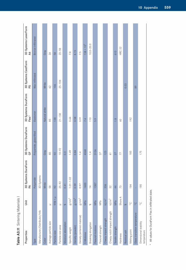
55910 Appendix
Tabl
e A3
.11�S
inte
ring
Mat
eria
ls I
Prop
ertie
sUn
it3D
Sys
tem
s Du
raFo
rm
PA3D
Sys
tem
s Du
raFo
rm
GF3D
Sys
tem
s Du
raFo
rm
Flex
*3D
Sys
tem
s Ca
stFo
rm
PS3D
Sys
tem
s La
serF
orm
A6
Type
Polya
mid
ePo
lyam
ide,
gla
ss-fi
lled
Elas
tom
erW
ax in
filtra
ted
Bron
ze in
filtra
ted
Man
ufac
ture
r/Di
strib
utor
/Inf
o3D
Sys
tem
s
Colo
rW
hite
Gray
Natu
ral w
hite
Whi
teGr
ay
Aver
age
part
icle
size
µ58
4885
6234
Part
icle
size
95%
< µ
9292
138
106
58
Part
icle
size
are
aµ
25–9
210
–92
21–1
3825
–106
20–5
8
Moi
stur
e ab
sorp
tion
%0.
410.
3
Spec
ific
weig
htg/
cm3
1.01
–1.0
21.
490.
447.
8
Dens
ity (p
owde
r)g/
cm3
0.59
0.84
0.58
8.15
Dens
ity (s
inte
red
mat
eria
l)g/
cm3
0.97
1.4
0.91
7.5
E-M
odul
usM
Pa16
0040
687.
413
8 ×
103
Brea
king
elo
ngat
ion
%14
1.4
110
10.0
–20.
0
Flex
ural
mod
ulus
MPa
1387
3106
5.9
Flex
ural
stre
ngth
MPa
37
Char
py im
pact
stre
ngth
kJ/m
233
612
3
Char
py n
otch
impa
ct s
treng
th
kJ/m
232
41
Tens
ile s
treng
thM
Pa44
271.
861
0
Hard
ness
Shor
e A
7377
60HR
C 22
Resid
ual a
sh%
0.03
Mel
ting
poin
t°C
184
185
192
Glas
s tra
nsiti
on te
mpe
ratu
re°C
–89
Dim
ensio
nal s
tabi
lity
tem
pera
ture
°C18
017
5
* Al
l val
ues
for D
uraF
orm
Fle
x in
infil
trate
d st
ate.
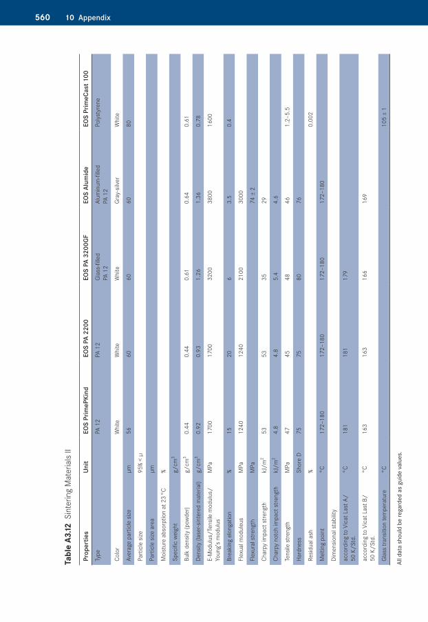
560 10 Appendix
Tabl
e A3
.12�S
inte
ring
Mat
eria
ls II
Prop
ertie
sUn
itEO
S Pr
imeP
Kind
EOS
PA 2
200
EOS
PA 3
200G
FEO
S Al
umid
eEO
S Pr
imeC
ast 1
00
Type
PA 1
2PA
12
Glas
s-fil
led
PA 1
2 Al
umin
um-fi
lled
PA
12
Polys
tyre
ne
Colo
rW
hite
Whi
teW
hite
Gray
-silv
erW
hite
Aver
age
part
icle
size
µm56
6060
6080
Part
icle
size
95%
< µ
Part
icle
size
are
aµm
Moi
stur
e ab
sorp
tion
at 2
3 °C
%
Spec
ific
weig
htg/
cm3
Bulk
den
sity
(pow
der)
g/cm
3 0.
440.
440.
610.
640.
61
Dens
ity (l
aser
-sin
tere
d m
ater
ial)
g/cm
3 0.
920.
931.
261.
360.
78
E-M
odul
us/T
ensil
e m
odul
us/
Youn
g’s
mod
ulus
MPa
1700
17
0032
0038
00
1600
Brea
king
elo
ngat
ion
%15
20
6
3.5
0.4
Flex
ual m
odul
eus
MPa
1240
12
40
2100
30
00
Flex
ural
stre
ngth
MPa
74 ±
2
Char
py im
pact
stre
ngth
kJ/m
253
53
35
29
Char
py n
otch
impa
ct s
treng
thkJ
/m2
4.8
4.8
5.4
4.6
Tens
ile s
treng
thM
Pa47
45
48
461.
2–5.
5
Hard
ness
Shor
e D
75
7580
76
Resid
ual a
sh%
0.00
2
Mel
ting
poin
t°C
172–
180
172–
180
172–
180
172–
180
Dim
ensio
nal s
tabi
lity
acco
rdin
g to
Vic
at L
ast A
/ 50
K/S
td.
°C18
118
117
9
acco
rdin
g to
Vic
at L
ast B
/ 50
K/S
td.
°C16
316
316
616
9
Glas
s tra
nsiti
on te
mpe
ratu
re°C
105
± 1
All d
ata
shou
ld b
e re
gard
ed a
s gu
ide
valu
es.
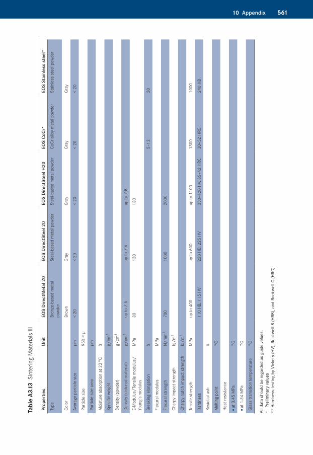
56110 Appendix
Tabl
e A3
.13�S
inte
ring
Mat
eria
ls III
Prop
ertie
sUn
itEO
S Di
rect
Met
al 2
0EO
S Di
rect
Stee
l 20
EOS
Dire
ctSt
eel H
20EO
S Co
Cr*
EOS
Stai
nles
s st
eel*
Type
Bron
ze-b
ased
met
al
powd
erSt
eel-b
ased
met
al p
owde
rSt
eel-b
ased
met
al p
owde
rCo
Cr a
lloy
met
al p
owde
rSt
ainl
ess
stee
l pow
der
Colo
rBr
own
Gray
Gray
Gray
Gray
Aver
age
part
icle
size
µm<
20<
20<
20<
20<
20
Part
icle
size
95%
< µ
Part
icle
size
are
aµm
Moi
stur
e ab
sorp
tion
at 2
3 °C
%
Spec
ific
weig
htg/
cm3
Dens
ity (p
owde
r)g/
cm3
Dens
ity (s
inte
red
mat
eria
l)g/
cm3
up to
7.6
up to
7.6
up to
7.8
E-M
odul
us/T
ensil
e m
odul
us/
Youn
g’s
mod
ulus
MPa
8013
018
0
Brea
king
elo
ngat
ion
%5–
1230
Flex
ural
mod
ulus
MPa
Flex
ural
stre
ngth
N/m
m2
700
1000
2000
Char
py im
pact
stre
ngth
kJ/m
2
Char
py n
otch
impa
ct s
treng
thkJ
/m2
Tens
ile s
treng
thM
Paup
to 4
00up
to 6
00up
to 1
100
1300
1000
Hard
ness
110
HB, 1
15 H
V22
0 HB
, 225
HV
350–
420
HV, 3
5–42
HRC
30–5
2 HR
C24
0 HB
Resid
ual a
sh%
Mel
ting
poin
t°C
Heat
resis
tanc
e
■ a
t 0.4
5 M
Pa°C
■ a
t 1.8
4 M
Pa°C
Glas
s tra
nsiti
on te
mpe
ratu
re°C
All d
ata
shou
ld b
e re
gard
ed a
s gu
ide
valu
es.
* Pr
elim
inar
y va
lues
** H
ardn
ess
test
ing
by V
icke
rs (H
V), R
ockw
ell B
(HRB
), an
d Ro
ckwe
ll C
(HRC
).
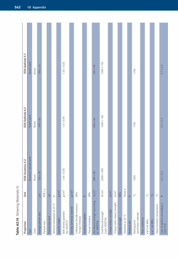
562 10 Appendix
Tabl
e A3
.14�S
inte
ring
Mat
eria
ls IV
Prop
ertie
sUn
itEO
S Ce
ram
ics
5.2
EOS
QuK
indz
4.2
EOS
QuK
indz
5.7
Type
Alum
inum
silic
ate
sand
Qua
rtz s
and
Qua
rtz s
and
Colo
rBr
own
Brow
nBr
own
Aver
age
part
icle
size
µm13
0 ±
2014
0 ±
2016
0 ±
10
Part
icle
size
95%
< µ
Part
icle
size
are
aµm
Moi
stur
e ab
sorp
tion
at 2
3 °C
%
Spec
ific
weig
htg/
cm3
Bulk
den
sity
(pow
der)
(by
VDGP
27)
g/cm
31.
64 ±
0.0
51.
4 ±
0.04
1.35
± 0
.03
Dens
ity (s
inte
red
mat
eria
l)g/
cm3
E-M
odul
us/T
ensil
e m
odul
us/
Youn
g’s
mod
ulus
MPa
Brea
king
elo
ngat
ion
%
Flex
ual m
odul
eus
MPa
Hot fl
exur
al s
treng
th (a
ccor
ding
to
VDG
P74)
N/cm
280
0 ±
8060
0 ±
6055
0 ±
55
Cold
flex
ural
stre
ngth
(n
ach
VDGP
74)
N/cm
220
00 ±
200
1600
± 1
6015
00 ±
150
Char
py im
pact
stre
ngth
kJ/m
2
Char
py n
otch
impa
ct s
treng
thkJ
/m2
Tens
ile s
treng
thM
Pa
Hard
ness
at 2
3 °C
Shor
e A
Resid
ual a
sh%
Mel
ting
poin
t (s
and
base
mat
eria
l)°C
1825
1700
1700
Heat
resis
tanc
e
■ a
t 0.4
5 M
Pa°C
■ a
t 1.8
4 M
Pa°C
Glas
s tra
nsiti
on te
mpe
ratu
re°C
Loss
on
igni
tion
(acc
ordi
ng to
VD
G-P7
4)%
5.2
± 0.
24.
2 ±
0.2
5.7
± 0.
2
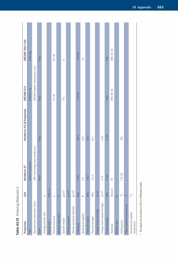
56310 Appendix
Tabl
e A3
.15�S
inte
ring
Mat
eria
ls V
Prop
ertie
sUn
itW
indf
orm
XT
Win
dfor
m P
ro B
Pol
yam
ide
ARCA
M H
13AR
CAM
Ti6
A114
V
Type
Carb
on c
ompo
site
CrM
oVa
Leg.
Tita
n Le
g.
Man
ufac
ture
r/Ve
rtre
iber
/Inf
osCR
P-Te
chno
logy
www
.win
dfor
m.it
ARCA
M S
wede
n ww
w.ar
cam
.com
Colo
rBl
ack
Gray
Gray
Gray
Aver
age
part
icle
size
µ
Part
icle
size
95%
< µ
Part
icle
size
are
aµ
15–4
020
–50
Moi
stur
e ab
sorp
tion
%
Spec
ific
weig
htg/
cm3
7.8
4
Dens
ity (p
owde
r)g/
cm3
Dens
ity (s
inte
red
mat
eria
l)g/
cm3
E-M
odul
usM
Pa73
2036
1221
0,00
012
8,00
0
Brea
king
elo
ngat
ion
%2.
63.
8110
Flex
ural
mod
ulus
MPa
1387
3106
Flex
ural
stre
ngth
MPa
131.
596
.1
Char
py im
pact
stre
ngth
kJ/m
2
Char
py n
otch
impa
ct s
treng
th
kJ/m
24.
732.
69
Tens
ile s
treng
thM
Pa77
.85
47.0
513
0093
0
Hard
ness
Shor
e A
92HR
C 48
–50
HRC
30–3
5
Resid
ual a
sh%
Mel
ting
poin
t°C
179.
3318
0
Glas
s tra
nsiti
on te
mpe
ratu
re°C
–
Dim
ensio
nal s
tabi
lity
tem
pera
ture
°C
* Al
l val
ues
for D
uraF
orm
Fle
x in
infil
trate
d st
ate.
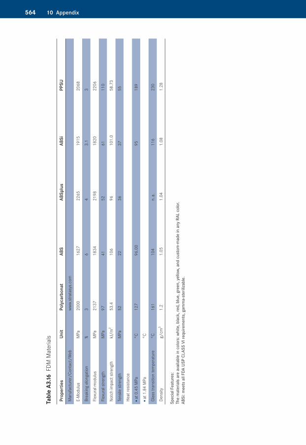
564 10 Appendix
Tabl
e A3
.16�F
DM M
ater
ials
Prop
ertie
sUn
itPo
lyca
rbon
atAB
SAB
Splu
sAB
SiPP
SU
Man
ufac
ture
r/Co
ntac
t/W
ebww
w.st
rata
sys.
com
E-M
odul
usM
Pa20
0016
2722
6519
1520
68
Brea
king
elo
ngat
ion
%3
64
3.1
3
Flex
ural
mod
ulus
MPa
2137
1834
2198
1820
2206
Flex
ural
stre
ngth
MPa
9741
5261
110
Notc
h im
pact
stre
ngth
kJ/m
253
.410
696
101.
058
.73
Tens
ile s
treng
thM
Pa52
2236
3755
Heat
resis
tanc
e
■ a
t 0.4
5 M
Pa°C
127
96.0
095
189
■ a
t 1.8
4 M
Pa°C
Glas
s tra
nsiti
on te
mpe
ratu
re°C
161
104
n. a.
116
230
Dens
ityg/
cm3
1.2
1.05
1.04
1.08
1.28
Spec
ial F
eatu
res:
The
mat
eria
ls a
re a
vaila
ble
in c
olor
s: w
hite
, bla
ck, r
ed, b
lue,
gre
en, y
ello
w, a
nd c
usto
m-m
ade
in a
ny R
AL c
olor
.AB
Si: m
eets
all
FDA
USP
CLAS
S VI
requ
irem
ents
, gam
ma-
ster
iliza
ble.
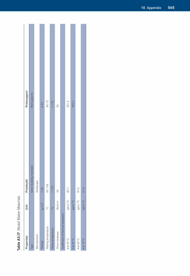
56510 Appendix
Tabl
e A3
.17�M
odel
Mak
er M
ater
ials
Prop
ertie
sUn
itPr
otob
uild
Prot
osup
port
Type
Gree
n bu
ildin
g m
ater
ials
Red
supp
orts
Man
ufac
ture
rSo
lidsc
ape
Dens
ityg/
cm3
1.25
0.93
Mel
ting
tem
pera
ture
°C92
–106
50–7
2
Flam
e te
mpe
ratu
re°C
> 17
5>
175
Shor
e ha
rdne
ssSh
ore
A45
33
Coeffi
cien
t of t
herm
al e
xpan
sion
■ a
t 50
°Cpp
m/°
C82
.735
1.3
■ a
t 55
°Cpp
m/°
C40
3.2
■ a
t 60
°Cpp
m/°
C87
.6
■ a
t 70
°Cpp
m/°
C91
.4
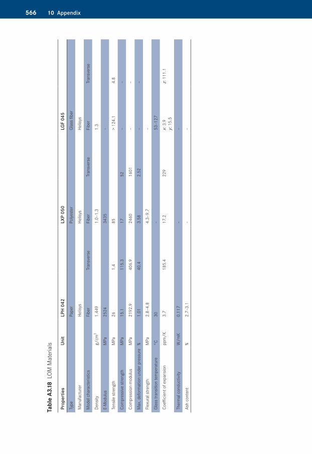
566 10 Appendix
Tabl
e A3
.18�L
OM M
ater
ials
Prop
ertie
sUn
itLP
H 04
2LX
P 05
0LG
F 04
5
Type
Pape
rPo
lyest
erGl
ass
fiber
Man
ufac
ture
rHe
lisys
Helis
ysHe
lisys
Mod
el c
hara
cter
istic
sFi
ber
Tran
sver
seFi
ber
Tran
sver
seFi
ber
Tran
sver
se
Dens
ityg/
cm3
1.44
91.
0–1.
31.
3
E-M
odul
usM
Pa25
2434
35–
Tens
ile s
treng
thM
Pa26
1.4
85>
124.
14.
8
Com
pres
sive
stre
ngth
MPa
15.1
115.
317
52–
–
Com
pres
sion
mod
ulus
MPa
2192
.940
6.9
2460
1601
––
Max
. def
orm
atio
n un
der p
ress
ure
%1.
0140
.43.
582.
52–
–
Flex
ural
stre
ngth
MPa
2.8–
4.8
4.3–
9.7
–
Glas
s tra
nsiti
on te
mpe
ratu
re°C
30–
53–1
27
Coeffi
cien
t of e
xpan
sion
ppm
/K3.
718
5.4
17.2
229
x: 3
.9
y: 1
5.5
z: 1
11.1
Ther
mal
con
duct
ivity
W/m
K0.
117
––
Ash
cont
ent
%2.
7–3.
1–
–
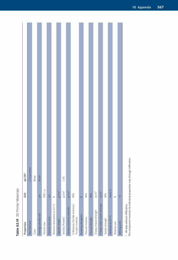
56710 Appendix
Tabl
e A3
.19�3
D Pr
inte
r Mat
eria
ls
Prop
ertie
sUn
itzp
130*
Man
ufac
ture
r Z
Corp
orat
ion
Colo
rW
hite
Aver
age
part
icle
size
µm50
.00
Part
icle
size
95%
< µ
Part
icle
size
are
aµm
Moi
stur
e ab
sorp
tion
at 2
3 °C
%
Spec
ific
weig
htg/
cm3
Dens
ity (P
owde
r)g/
cm3
1.60
Dens
ity (s
inte
red
mat
eria
l)g/
cm3
E-M
odul
us/T
ensil
e m
odul
us/
Youn
g’s
mod
ulus
MPa
Brea
king
elo
ngat
ion
%
Flex
ural
mod
ulus
MPa
Flex
ural
stre
ngth
MPa
Char
py im
pact
stre
ngth
kJ/m
2
Char
py n
otch
impa
ct s
treng
thkJ
/m2
Tens
ile s
treng
thM
Pa
Hard
ness
at 2
3 °C
Shor
e A
Resid
ual a
sh%
Mel
ting
poin
t°C
* Al
l dat
a w
ithou
t infi
ltrat
ion.
Th
e co
mpo
nent
rece
ives
its in
divid
ual p
rope
rtie
s on
ly th
roug
h in
filtra
tion.
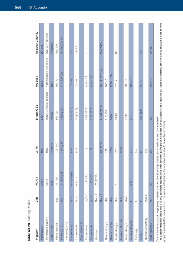
568 10 Appendix
Tabl
e A3
.20�
Cast
ing
Resin
s
Prop
erty
Unit
PX 7
7421
70Bi
resi
n G
55M
G 80
51M
egith
an 2
MD7
87
Man
ufac
ture
rAx
son
HEK
SIKA
ebal
taBI
OTOO
L
Pron
ounc
ed p
rope
rty
Elas
ticHa
rdIm
pact
/ fl
exur
al s
treng
thHi
gh-te
mpe
ratu
re re
sista
ntCl
ear (
UV re
sista
nt)
Aspe
ct/C
olor
Blac
kYe
llowi
shOp
aque
Blac
kTr
ansp
aren
t
Mixi
ng ra
tio A
:Bg :
g44
: 100
100
: 150
80 : 1
0010
0 : 7
010
0 : 3
00
Pot l
ife (g
; °C)
min
2–3
(100
; 25)
4 (1
00; 2
5)4
(300
; 20)
5–7
(200
; 20)
15–2
0 (2
00; 2
0)
Visc
osity
(25
°C)
Com
pone
nt A
Pa ·
s0.
025–
0.04
50.
631.
45 (2
3 °C
)0.
7 ±
0.10
1.5
Com
pone
nt B
Pa ·
s0.
8–1.
20.
230.
3 (2
3 °C
)0.
7 ±
0.10
0.8–
2.2
Spec
. Wei
ght (
25°)
Com
pone
nt A
kg/d
m3
1.18
–1.2
21.
111.
06 (2
3 °C
)1.
14 ±
0.2
–
Com
pone
nt B
kg/d
m3
1.03
–1.0
71.
221.
22 (2
3 °C
)1.
16 ±
0.2
–
Hard
ness
Shor
e A
75 (2
3 °C
)
Shor
e D
82 (2
3 °C
)81
–84
(23
°C)
80 ±
3 (2
3 Gr
ad)
85–8
7 (R
T)
Flex
ural
stre
ngth
MPA
120
110–
120
100
± 5
Flex
ural
mod
ulus
MPA
2690
2800
1930
± 1
00
Tens
ile s
treng
thM
PA7
78.5
70–8
067
± 5
90
Tens
ion/
E-M
odul
usM
PA35
30
Impa
ct s
treng
thkJ
/m2
> 10
063
± 1
0
Brea
king
elo
ngat
ion
%30
06.
56–
810
.5 ±
2
Stre
tchi
ng%
5.5
Shrin
k%
0.1
0.25
–0.3
5ca
. 0.3
0.1
Ther
mal
con
duct
ivity
W/m
K22
4
Heat
resis
tanc
e°C
8085
8012
0 ±
390
–100
Due
to th
e w
ide
prod
uct r
ange
, eve
ry m
anuf
actu
rer a
nd th
eref
ore
all p
rodu
cts
cann
ot b
e lis
ted
and
char
acte
rized
.Th
e ca
stin
g m
ater
ials
list
ed h
ere
are
only
exa
mpl
es re
pres
entin
g w
hat d
iffer
ent p
rono
unce
d pr
oper
ties
can
be c
ruci
al fo
r the
righ
t cho
ice.
The
re a
re c
erta
inly
oth
er m
ater
ials
that
are
sim
ilar o
r hav
e pr
oper
ties
even
bet
ter t
han
expe
cted
. For
spe
cific
info
rmat
ion,
the
man
ufac
ture
r sho
uld
be c
onta
cted
dire
ctly.
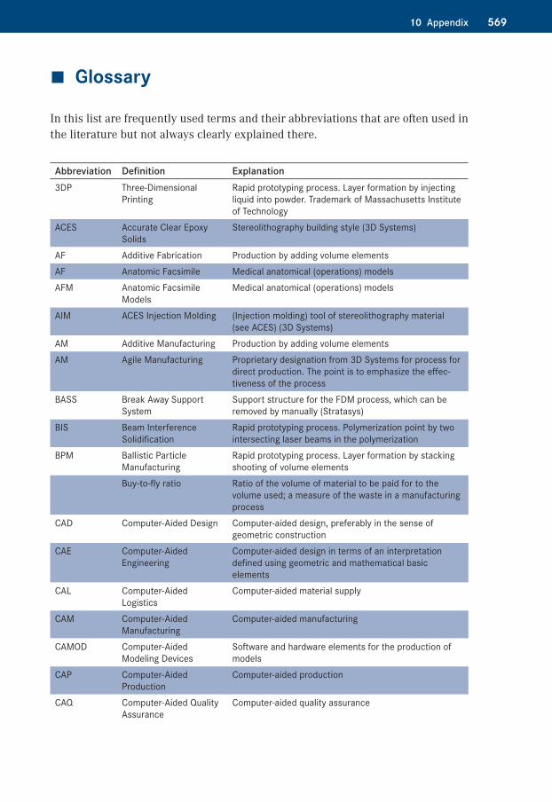
56910 Appendix
�� Glossary
In this list are frequently used terms and their abbreviations that are often used in the literature but not always clearly explained there.
Abbreviation Definition Explanation3DP Three-Dimensional
PrintingRapid prototyping process. Layer formation by injecting liquid into powder. Trademark of Massachusetts Institute of Technology
ACES Accurate Clear Epoxy Solids
Stereolithography building style (3D Systems)
AF Additive Fabrication Production by adding volume elementsAF Anatomic Facsimile Medical anatomical (operations) modelsAFM Anatomic Facsimile
ModelsMedical anatomical (operations) models
AIM ACES Injection Molding (Injection molding) tool of stereolithography material (see ACES) (3D Systems)
AM Additive Manufacturing Production by adding volume elementsAM Agile Manufacturing Proprietary designation from 3D Systems for process for
direct production. The point is to emphasize the effec-tiveness of the process
BASS Break Away Support System
Support structure for the FDM process, which can be removed by manually (Stratasys)
BIS Beam Interference Solidification
Rapid prototyping process. Polymerization point by two intersecting laser beams in the polymerization
BPM Ballistic Particle Manufacturing
Rapid prototyping process. Layer formation by stacking shooting of volume elements
Buy-to-fly ratio Ratio of the volume of material to be paid for to the volume used; a measure of the waste in a manufacturing process
CAD Computer-Aided Design Computer-aided design, preferably in the sense of geometric construction
CAE Computer-Aided Engineering
Computer-aided design in terms of an interpretation defined using geometric and mathematical basic elements
CAL Computer-Aided Logistics
Computer-aided material supply
CAM Computer-Aided Manufacturing
Computer-aided manufacturing
CAMOD Computer-Aided Modeling Devices
Software and hardware elements for the production of models
CAP Computer-Aided Production
Computer-aided production
CAQ Computer-Aided Quality Assurance
Computer-aided quality assurance
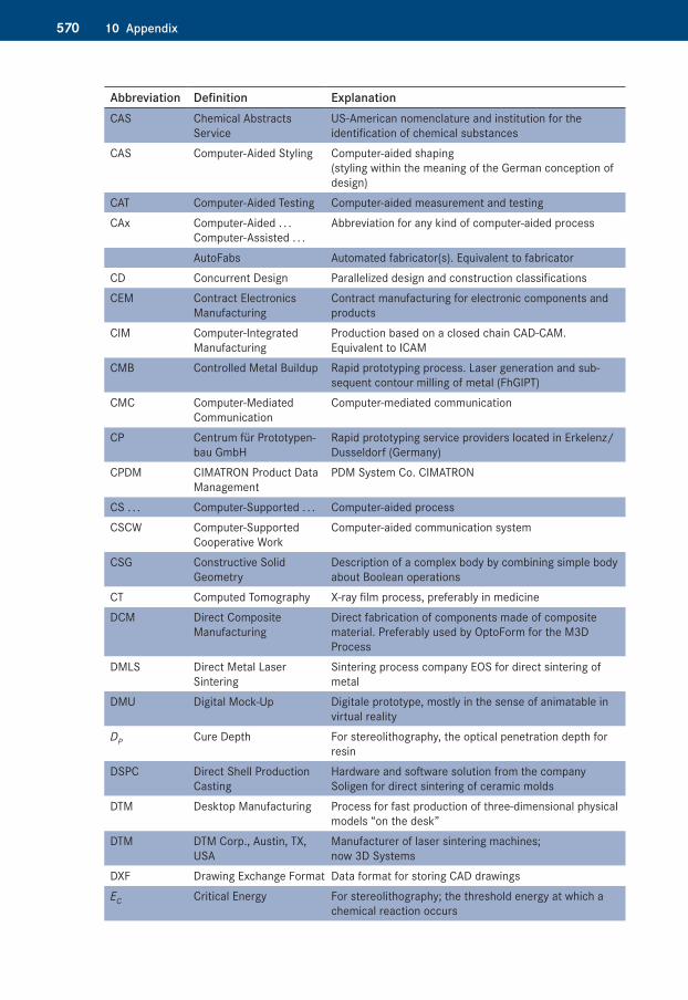
570 10 Appendix
Abbreviation Definition ExplanationCAS Chemical Abstracts
ServiceUS-American nomenclature and institution for the identification of chemical substances
CAS Computer-Aided Styling Computer-aided shaping (styling within the meaning of the German conception of design)
CAT Computer-Aided Testing Computer-aided measurement and testingCAx Computer-Aided . . .
Computer-Assisted . . .Abbreviation for any kind of computer-aided process
AutoFabs Automated fabricator(s). Equivalent to fabricatorCD Concurrent Design Parallelized design and construction classificationsCEM Contract Electronics
ManufacturingContract manufacturing for electronic components and products
CIM Computer-Integrated Manufacturing
Production based on a closed chain CAD-CAM. Equivalent to ICAM
CMB Controlled Metal Buildup Rapid prototyping process. Laser generation and sub-sequent contour milling of metal (FhGIPT)
CMC Computer-Mediated Communication
Computer-mediated communication
CP Centrum für Prototypen-bau GmbH
Rapid prototyping service providers located in Erkelenz/Dusseldorf (Germany)
CPDM CIMATRON Product Data Management
PDM System Co. CIMATRON
CS . . . Computer-Supported . . . Computer-aided processCSCW Computer-Supported
Cooperative WorkComputer-aided communication system
CSG Constructive Solid Geometry
Description of a complex body by combining simple body about Boolean operations
CT Computed Tomography X-ray film process, preferably in medicineDCM Direct Composite
ManufacturingDirect fabrication of components made of composite material. Preferably used by OptoForm for the M3D Process
DMLS Direct Metal Laser Sintering
Sintering process company EOS for direct sintering of metal
DMU Digital Mock-Up Digitale prototype, mostly in the sense of animatable in virtual reality
DP Cure Depth For stereolithography, the optical penetration depth for resin
DSPC Direct Shell Production Casting
Hardware and software solution from the company Soligen for direct sintering of ceramic molds
DTM Desktop Manufacturing Process for fast production of three-dimensional physical models “on the desk”
DTM DTM Corp., Austin, TX, USA
Manufacturer of laser sintering machines; now 3D Systems
DXF Drawing Exchange Format Data format for storing CAD drawingsEC Critical Energy For stereolithography; the threshold energy at which a
chemical reaction occurs
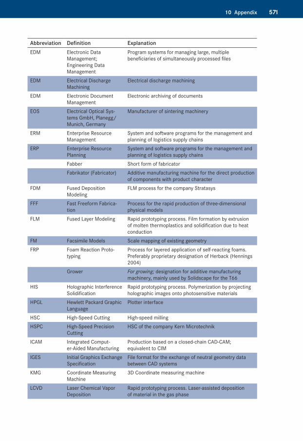
57110 Appendix
Abbreviation Definition ExplanationEDM Electronic Data
Management; Engineering Data Management
Program systems for managing large, multiple beneficiaries of simultaneously processed files
EDM Electrical Discharge Machining
Electrical discharge machining
EDM Electronic Document Management
Electronic archiving of documents
EOS Electrical Optical Sys-tems GmbH, Planegg/Munich, Germany
Manufacturer of sintering machinery
ERM Enterprise Resource Management
System and software programs for the management and planning of logistics supply chains
ERP Enterprise Resource Planning
System and software programs for the management and planning of logistics supply chains
Fabber Short form of fabricator Fabrikator (Fabricator) Additive manufacturing machine for the direct production
of components with product characterFDM Fused Deposition
ModelingFLM process for the company Stratasys
FFF Fast Freeform Fabrica-tion
Process for the rapid production of three-dimensional physical models
FLM Fused Layer Modeling Rapid prototyping process. Film formation by extrusion of molten thermoplastics and solidification due to heat conduction
FM Facsimile Models Scale mapping of existing geometryFRP Foam Reaction Proto-
typingProcess for layered application of self-reacting foams. Preferably proprietary designation of Herback (Hennings 2004)
Grower For growing; designation for additive manufacturing machinery, mainly used by Solidscape for the T66
HIS Holographic Interference Solidification
Rapid prototyping process. Polymerization by projecting holographic images onto photosensitive materials
HPGL Hewlett Packard Graphic Language
Plotter interface
HSC High-Speed Cutting High-speed millingHSPC High-Speed Precision
CuttingHSC of the company Kern Microtechnik
ICAM Integrated Comput-er-Aided Manufacturing
Production based on a closed-chain CAD-CAM; equivalent to CIM
IGES Initial Graphics Exchange Specification
File format for the exchange of neutral geometry data between CAD systems
KMG Coordinate Measuring Machine
3D Coordinate measuring machine
LCVD Laser Chemical Vapor Deposition
Rapid prototyping process. Laser-assisted deposition of material in the gas phase
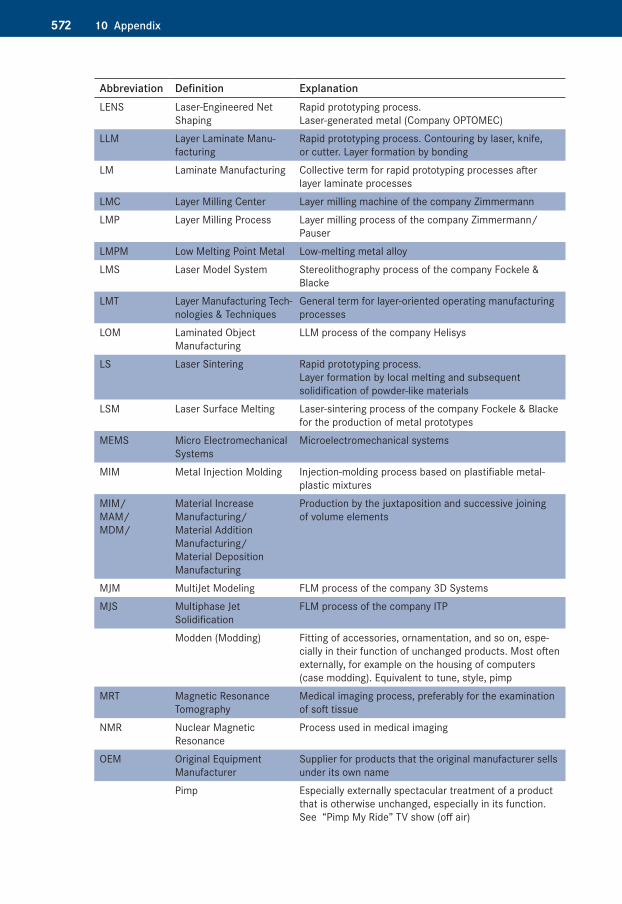
572 10 Appendix
Abbreviation Definition ExplanationLENS Laser-Engineered Net
ShapingRapid prototyping process. Laser-generated metal (Company OPTOMEC)
LLM Layer Laminate Manu-facturing
Rapid prototyping process. Contouring by laser, knife, or cutter. Layer formation by bonding
LM Laminate Manufacturing Collective term for rapid prototyping processes after layer laminate processes
LMC Layer Milling Center Layer milling machine of the company ZimmermannLMP Layer Milling Process Layer milling process of the company Zimmermann/
PauserLMPM Low Melting Point Metal Low-melting metal alloyLMS Laser Model System Stereolithography process of the company Fockele &
BlackeLMT Layer Manufacturing Tech-
nologies & TechniquesGeneral term for layer-oriented operating manufacturing processes
LOM Laminated Object Manufacturing
LLM process of the company Helisys
LS Laser Sintering Rapid prototyping process. Layer formation by local melting and subsequent solidification of powder-like materials
LSM Laser Surface Melting Laser-sintering process of the company Fockele & Blacke for the production of metal prototypes
MEMS Micro Electromechanical Systems
Microelectromechanical systems
MIM Metal Injection Molding Injection-molding process based on plastifiable metal- plastic mixtures
MIM/ MAM/ MDM/
Material Increase Manufacturing/ Material Addition Manufacturing/ Material Deposition Manufacturing
Production by the juxtaposition and successive joining of volume elements
MJM MultiJet Modeling FLM process of the company 3D SystemsMJS Multiphase Jet
SolidificationFLM process of the company ITP
Modden (Modding) Fitting of accessories, ornamentation, and so on, espe-cially in their function of unchanged products. Most often externally, for example on the housing of computers (case modding). Equivalent to tune, style, pimp
MRT Magnetic Resonance Tomography
Medical imaging process, preferably for the examination of soft tissue
NMR Nuclear Magnetic Resonance
Process used in medical imaging
OEM Original Equipment Manufacturer
Supplier for products that the original manufacturer sells under its own name
Pimp Especially externally spectacular treatment of a product that is otherwise unchanged, especially in its function. See “Pimp My Ride” TV show (off air)
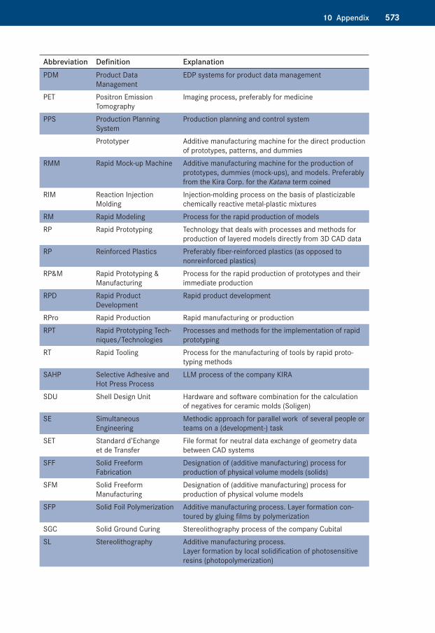
57310 Appendix
Abbreviation Definition ExplanationPDM Product Data
ManagementEDP systems for product data management
PET Positron Emission Tomography
Imaging process, preferably for medicine
PPS Production Planning System
Production planning and control system
Prototyper Additive manufacturing machine for the direct production of prototypes, patterns, and dummies
RMM Rapid Mock-up Machine Additive manufacturing machine for the production of prototypes, dummies (mock-ups), and models. Preferably from the Kira Corp. for the Katana term coined
RIM Reaction Injection Molding
Injection-molding process on the basis of plasticizable chemically reactive metal-plastic mixtures
RM Rapid Modeling Process for the rapid production of modelsRP Rapid Prototyping Technology that deals with processes and methods for
production of layered models directly from 3D CAD dataRP Reinforced Plastics Preferably fiber-reinforced plastics (as opposed to
nonreinforced plastics)RP&M Rapid Prototyping &
ManufacturingProcess for the rapid production of prototypes and their immediate production
RPD Rapid Product Development
Rapid product development
RPro Rapid Production Rapid manufacturing or productionRPT Rapid Prototyping Tech-
niques/TechnologiesProcesses and methods for the implementation of rapid prototyping
RT Rapid Tooling Process for the manufacturing of tools by rapid proto-typing methods
SAHP Selective Adhesive and Hot Press Process
LLM process of the company KIRA
SDU Shell Design Unit Hardware and software combination for the calculation of negatives for ceramic molds (Soligen)
SE Simultaneous Engineering
Methodic approach for parallel work of several people or teams on a (development-) task
SET Standard d’Echange et de Transfer
File format for neutral data exchange of geometry data between CAD systems
SFF Solid Freeform Fabrication
Designation of (additive manufacturing) process for production of physical volume models (solids)
SFM Solid Freeform Manu facturing
Designation of (additive manufacturing) process for production of physical volume models
SFP Solid Foil Polymerization Additive manufacturing process. Layer formation con-toured by gluing films by polymerization
SGC Solid Ground Curing Stereolithography process of the company CubitalSL Stereolithography Additive manufacturing process.
Layer formation by local solidification of photosensitive resins (photopolymerization)
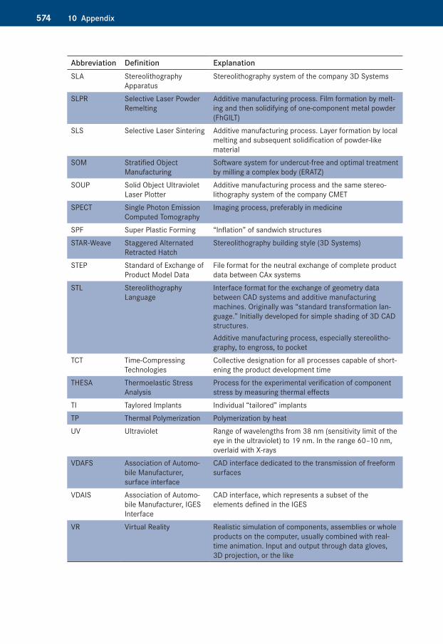
574 10 Appendix
Abbreviation Definition ExplanationSLA Stereolithography
ApparatusStereolithography system of the company 3D Systems
SLPR Selective Laser Powder Remelting
Additive manufacturing process. Film formation by melt-ing and then solidifying of one-component metal powder (FhGILT)
SLS Selective Laser Sintering Additive manufacturing process. Layer formation by local melting and subsequent solidification of powder-like material
SOM Stratified Object Manu facturing
Software system for undercut-free and optimal treatment by milling a complex body (ERATZ)
SOUP Solid Object Ultraviolet Laser Plotter
Additive manufacturing process and the same stereo-lithography system of the company CMET
SPECT Single Photon Emission Computed Tomography
Imaging process, preferably in medicine
SPF Super Plastic Forming “Inflation” of sandwich structuresSTAR-Weave Staggered Alternated
Retracted HatchStereolithography building style (3D Systems)
STEP Standard of Exchange of Product Model Data
File format for the neutral exchange of complete product data between CAx systems
STL Stereolithography Language
Interface format for the exchange of geometry data between CAD systems and additive manufacturing machines. Originally was “standard transformation lan-guage.” Initially developed for simple shading of 3D CAD structures.Additive manufacturing process, especially stereolitho-graphy, to engross, to pocket
TCT Time-Compressing Technologies
Collective designation for all processes capable of short-ening the product development time
THESA Thermoelastic Stress Analysis
Process for the experimental verification of component stress by measuring thermal effects
TI Taylored Implants Individual “tailored” implantsTP Thermal Polymerization Polymerization by heatUV Ultraviolet Range of wavelengths from 38 nm (sensitivity limit of the
eye in the ultraviolet) to 19 nm. In the range 60–10 nm, overlaid with X-rays
VDAFS Association of Automo-bile Manufacturer, surface interface
CAD interface dedicated to the transmission of freeform surfaces
VDAIS Association of Automo-bile Manufacturer, IGES Interface
CAD interface, which represents a subset of the elements defined in the IGES
VR Virtual Reality Realistic simulation of components, assemblies or whole products on the computer, usually combined with real-time animation. Input and output through data gloves, 3D projection, or the like