Embed Size (px)
Citation preview
ADDIS ABABA UNIVERSITY
INSTITUTE OF TECHNOLOGY
CENTER OF ENERGY TECHNOLOGY
DESIGN AND ANALYSIS OF SOLAR THERMAL SYSTEM FOR HOT
WATER SUPPLY TO MINILK II HOSPITAL NEW BUILDING
A thesis submitted to the School of Graduate Studies of Addis Ababa University
Institute of Technology in partial fulfillment for the Degree of Masters of
Science in Energy of Technology
By: Dagim Kebede
Advisor: Dr. Yilma Tadesse
June, 2016
Addis Ababa,
Ethiopia
Design and Analysis of Solar Thermal System for Hot Water Supply to Minilik II Hospital New Building
i
By: Dagim Kebede
Adviser: Dr. Yilma Tadesse
CERTIFICATION
I, the undersigned, certify that I read and hear by recommend for acceptance by Addis Ababa
University Institute of Technology Energy Center a thesis entitled “Design and Analysis of Solar
Thermal System for Hot Water Supply to Minilik II Hospital New Building.” This certificate
used as in partial fulfillment of the requirements for the degree of Masters of Science in Energy
Technology.
Signature: _________________________
Date: _________________________
Dr. Yilma Tadesse
(Supervisor)
Design and Analysis of Solar Thermal System for Hot Water Supply to Minilik II Hospital New Building
ii
By: Dagim Kebede
Adviser: Dr. Yilma Tadesse
DECLARATION
I, Dagim Kebede, First, I declare that this thesis is the result of my own work and that all source
or materials used for this thesis have been duly acknowledged. This thesis is submitted in partial
fulfillment of the requirements for Master‟s Degree in Energy Technology at Addis Ababa
University and to be made available at the University‟s Library under the rule of the Library. I
confidently declare that this thesis has not been submitted to any other institutions anywhere for
the award of any academic degree, diploma, or certificate.
Signature: _________________________
Date: _________________________
Dagim Kebede
Design and Analysis of Solar Thermal System for Hot Water Supply to Minilik II Hospital New Building
iii
By: Dagim Kebede
Adviser: Dr. Yilma Tadesse
Addis Ababa University Institute of Technology
School of Graduate
Energy Center
Design and Analysis of Solar Thermal System for Hot Water Supply to
Minilik II Hospital New Building
By: Dagim Kebede
Approved by Board of Examiners

Design and Analysis of Solar Thermal System for Hot Water Supply to Minilik II Hospital New Building
iv
By: Dagim Kebede
Adviser: Dr. Yilma Tadesse
ACKNOWLEDGMENT
First I would like to give an Enormous thanks to the Almighty God who gives me patient,
courage and wisdom to finish this project.
I would like to express the deepest sadness for my former adviser Dr.-Ing Abebayehu Assefa
whom suddenly passes away. I am grateful for his support, kind help and encouragement. And
also, I express my sincere gratitude to my new advisor Dr. Yilma Tadesse for giving me the
opportunity to work on this project and for his guidance and encouragement without which this
work could have not been completed. I am also grateful to Dr. Solomon Abebe head of Energy
Center in Addis Ababa University, Institute of Technology, for his kind help on different
occasions. Last but not least, I would like to thank my family and friends who were always
besides me and played a great role in completion of my work.
Design and Analysis of Solar Thermal System for Hot Water Supply to Minilik II Hospital New Building
v
By: Dagim Kebede
Adviser: Dr. Yilma Tadesse
TABLE OF CONTENTS
CERTIFICATION ............................................................................................................................i
DECLARATION ............................................................................................................................. ii
ACKNOWLEDGMENT................................................................................................................. iv
LIST OF FIGURES ........................................................................................................................ ix
LIST OF TABLES .......................................................................................................................... xi
ABBREVIATION.......................................................................................................................... xii
NOMENCLATURE ..................................................................................................................... xiii
ABSTRACT................................................................................................................................. xvii
CHAPTER 1 .................................................................................................................................. 1
INTRODUCTION......................................................................................................................... 1
1.1 Statement of the Problem .....................................................................................................2
1.2 Objectives ...........................................................................................................................3
1.3 Scope ..................................................................................................................................3
1.4 Significance.........................................................................................................................4
1.5 Organization........................................................................................................................4
CHAPTER 2 .................................................................................................................................. 6
LITERATURE REVIEW ............................................................................................................ 6
2.1 Background .........................................................................................................................6
2.2 Type of Solar Thermal Collector ...........................................................................................7
2.3 Solar water heating system ...................................................................................................9
2.4 Factors Affecting Solar Water Heating (SWH) Performance ................................................. 11
2.5 Summary of Literature Review ........................................................................................... 13
CHAPTER 3 ................................................................................................................................ 14
HOT WATER DEMAND OF MINILIK II HOSPITAL ........................................................ 14
3.1 Introduction....................................................................................................................... 14
3.2 Data from Minilik II Hospital ............................................................................................. 15
3.3 Determining Hot water demand of the Hospital.................................................................... 15
3.4 Hot Water Consumption Pattern ......................................................................................... 19
3.5 Hot Water Storage Tank Capacity ....................................................................................... 20
3.6 Energy Capacity of a Storage Unit ...................................................................................... 21
Design and Analysis of Solar Thermal System for Hot Water Supply to Minilik II Hospital New Building
vi
By: Dagim Kebede
Adviser: Dr. Yilma Tadesse
CHAPTER 4 ................................................................................................................................ 22
AVAILABLE SOLAR RADIATION DATA ........................................................................... 22
4.1 Introduction....................................................................................................................... 22
4.2 Incident Solar Radiation ..................................................................................................... 23
4.3 Radiation Factors ............................................................................................................... 27
4.4 Basic Sun-Earth Angles...................................................................................................... 28
CHAPTER 5 ................................................................................................................................ 30
FLAT PLATE COLLECTOR DESIGN ................................................................................... 30
5.1 Introduction....................................................................................................................... 30
5.2 Component of Flat Plate Collector ...................................................................................... 30
5.3 Material Selection .............................................................................................................. 31
5.4 Assumption for Design....................................................................................................... 33
5.5 Theoretical Designing of Collector...................................................................................... 34
5.6 Area of a Collector............................................................................................................. 42
5.7 Pressure Drop in the Collector ............................................................................................ 44
5.8 Analysis Parameters ........................................................................................................... 48
CHAPTER 6 ................................................................................................................................ 50
THERMAL STORAGE TANK AND INSULATION ............................................................. 50
6.1 Introduction....................................................................................................................... 50
6.2 Material Selection .............................................................................................................. 50
6.3 Optimization of Thermal Storage Tank................................................................................ 51
6.4 Optimization of Insulation Thickness .................................................................................. 53
6.5 Optimization of Storage Tank Thickness and Outer Diameter ............................................... 56
6.6 Technical Data of Storage Tank .......................................................................................... 60
CHAPTER 7 ................................................................................................................................ 61
TRANSIENT ANALYSIS OF FLAT-PLATE SOLAR COLLECTOR ................................ 61
7.1 Transient Analysis of Solar Water Heater ............................................................................ 61
7.2 Assumptions for Transient Analysis of Flat Plate Collector................................................... 62
7.3 Basic Energy Balance Equation .......................................................................................... 63
7.4 Transient Temperature Analysis of Collector System ........................................................... 67
7.5 The Heat Transfer Correlations ........................................................................................... 69
Design and Analysis of Solar Thermal System for Hot Water Supply to Minilik II Hospital New Building
vii
By: Dagim Kebede
Adviser: Dr. Yilma Tadesse
CHAPTER 8 ................................................................................................................................ 74
MATHEMATICAL MODEL PROGRAMING ...................................................................... 74
8.1 MATLAB Input Parameters................................................................................................ 74
8.2 Expected Output of MATLAB............................................................................................ 75
8.3 Procedure for Simulation of Solar Thermal Water Heater ..................................................... 75
CHAPTER 9 ................................................................................................................................ 79
RESULTS AND DISCUSSION ................................................................................................. 79
9.1 Solar Contribution to the Heating Load ............................................................................... 79
9.2 Outlet Water Temperature Graph ........................................................................................ 80
9.3 Hourly Useful Heat Gain .................................................................................................... 83
9.4 Collector Efficiency ........................................................................................................... 84
CHAPTER 10 .............................................................................................................................. 85
PUMP AND CONTROL SYSTEM SELECTION .................................................................. 85
10.1 Arrays of Collectors ........................................................................................................... 85
10.2 Pipe Length ....................................................................................................................... 88
10.3 Selection of Pump .............................................................................................................. 91
10.4 Control Element................................................................................................................. 95
CHAPTER 11 .............................................................................................................................. 98
FINANCIAL ANALYSIS ........................................................................................................... 98
11.1 Costs of Solar Process Systems ........................................................................................... 98
11.2 Operating, Maintenance and Replacement Cost.................................................................. 100
11.3 Investment cost................................................................................................................ 101
11.4 Economic Analysis .......................................................................................................... 102
11.5 Payback Period ................................................................................................................ 104
CHAPTER 12 ............................................................................................................................ 105
CONCLUSIONS AND RECOMMENDATIONS .................................................................. 105
12.1 Conclusion ...................................................................................................................... 105
12.2 Recommendation ............................................................................................................. 106
REFERENCE ............................................................................................................................ 107
Design and Analysis of Solar Thermal System for Hot Water Supply to Minilik II Hospital New Building
viii
By: Dagim Kebede
Adviser: Dr. Yilma Tadesse
APPENDIX ................................................................................................................................ 109
ANNEX A: MATLAB PROGRAM CODE .................................................................................. 109
ANNEX (A-1): Mass flow rate................................................................................................. 109
ANNEX (A-2): Plate Thickness ............................................................................................... 109
ANNEX (A-3): Riser Tube Inner Diameter ............................................................................... 110
ANNEX (A-4): Riser Tube Outer Diameter............................................................................... 112
ANNEX (A-5): Number of Riser Tube ..................................................................................... 113
ANNEX (A-6): Header Tube Diameter ..................................................................................... 114
ANNEX (A-7): Insulation Thickness Optimization .................................................................... 115
ANNEX (A-8): Storage Tank Thickness Optimization ............................................................... 116
ANNEX (A-9): Transient Analysis of Temperature ................................................................... 116
ANNEX B: GRAPHS OF OUTLET WATER TEMPERATURE ANALYSIS ................................ 123
ANNEX C: PROPERTIES OF VARIOUS MATERIALS ............................................................. 124
ANNEX D: MOODY CHART .................................................................................................... 127
Design and Analysis of Solar Thermal System for Hot Water Supply to Minilik II Hospital New Building
ix
By: Dagim Kebede
Adviser: Dr. Yilma Tadesse
LIST OF FIGURES
Figure 2.1: Typical Flat Plate Collectors ....................................................................................... 7
Figure 2.2: Evacuated tube collector (flooded evacuated tube and heat pipe evacuated tube) ..... 8
Figure 2.3: Thermosyphon SWH system..................................................................................... 10
Figure 2.4: Direct Active SWH System....................................................................................... 11
Figure 3.1: Daily Hot Water Demand of each Appliance............................................................ 19
Figure 3.2: Hot Water Demand Distribution over the Time of the Day ...................................... 19
Figure 3.3: Daily Hot Water Consumption Pattern of Minilik II Hospital. ................................. 20
Figure 4.1: Average Monthly Global Radiations......................................................................... 24
Figure 4.2: Average Yearly Global Radiations............................................................................ 25
Figure 5.1: Components of Flat Plate Collector .......................................................................... 31
Figure 5.2: The Relation of Mass Flow Rate with efficiency and outlet Temperature of water . 34
Figure 5.3: Sheet and tube dimensions ........................................................................................ 35
Figure 5.4: Relations of Absorber Plate Thickness and Efficiency ............................................. 37
Figure 5.5: Relations between Inner Diameter of Riser Tube and Efficiency............................. 38
Figure 5.6: Relations of Inner Diameter of Riser Tube with Pressure and Velocity ................... 38
Figure 5.7: Relations of Outer Diameter of Riser Tube and Efficiency ...................................... 39
Figure 5.8: Relation of Pressure Drop with Number of Riser Tube ............................................ 40
Figure 5.9: Pressure Drop and Velocity with Header Diameter .................................................. 41
Figure 5.10: Schematic Representation of the flow in the collector............................................ 44
Figure 6.1: Optimum Thickness of Insulation on the Basis of Minimum Total Cost. ................ 55
Figure 6.2: Optimum Thickness of Storage Tank on the Basis of Minimum Total Cost. ........... 58
Figure 6.3: Thicknesses of the Storage Tank and Side Insulation ............................................... 59
Figure 7.1: Cross-Section of the Flat Plat Collector .................................................................... 61
Figure 7.2: Heat Energy Balance of Glass Cover. ....................................................................... 64
Figure 7.3: Heat Energy Balance of Absorber Plate. ................................................................... 65
Figure 7.4: Energy balance of the working fluid in flat-plate solar collector.............................. 66
Figure 7.5: Energy balance in a control volume of storage tank. ................................................ 67
Figure 7.6: Thermal Networks for a One-Cover Flat-Plate Collector ......................................... 69
Design and Analysis of Solar Thermal System for Hot Water Supply to Minilik II Hospital New Building
x
By: Dagim Kebede
Adviser: Dr. Yilma Tadesse
Figure 8.1 (a) Flowchart of Simulation Programme .................................................................... 77
Figure 8.1 (b) Flowchart of Simulation Programme (contd.), ..................................................... 78
Figure 9.1: Solar Radiations for Minilik II Hospital ................................................................... 79
Figure 9.2: Outlet Water Temperatures for Different Number of Nodes .................................... 80
Figure 9.3: Outlet Water Temperatures for Different time period............................................... 81
Figure 9.4: Simulated Hourly Outlet Water Temperatures for Various Seasons ........................ 82
Figure 9.5: Simulated Hourly Storage Tank Temperatures for Various Seasons ........................ 82
Figure 9.6: Hourly Useful Heat Gain........................................................................................... 83
Figure 9.7: Efficiency for July 17 and November 14 .................................................................. 84
Figure 10.1: Collector modules in parallel (a) and series (b). ..................................................... 85
Figure 10.2: Collector Array (a) and Collector Module with Connection Line (b) ..................... 86
Figure 10.3: Clearance of Collector Array System...................................................................... 87
Figure 10.4: Positioning of Differential Controller ..................................................................... 96
Figure (B-1): Outlet Water Temperature for Winter Season ..................................................... 123
Figure (B-2): Outlet Water Temperature for Spring Season ..................................................... 123
Figure (B-3): Outlet Water Temperature for Summer Season................................................... 123
Figure (B-4): Outlet Water Temperature for Autumn Season ................................................... 124
Figure (D-1): Moody Chart........................................................................................................ 127
Design and Analysis of Solar Thermal System for Hot Water Supply to Minilik II Hospital New Building
xi
By: Dagim Kebede
Adviser: Dr. Yilma Tadesse
LIST OF TABLES
Table 3.1: Data from Minilik II Hospital ..................................................................................... 15
Table 3.2: Standard Hot Water Demand for Hospital.................................................................. 15
Table 3.3: Hot Water Demand for each Appliance of the Hospital ............................................. 16
Table 3.4: Hot water demand of the Hospital per Services ......................................................... 18
Table 3.5: Total Hot water demand of the Hospital per Services ................................................ 18
Table 3.6: Summaries of Hot Water, Storage Tank and Energy Capacity Needed ..................... 21
Table 4.1: Average Monthly Global Radiation (AMGR) data from year (2010 to 2015) ........... 24
Table 4.2: Average Yearly Global Radiations ............................................................................. 25
Table 4.3: Average Monthly Diffuse Radiations ......................................................................... 26
Table 4.4: Average Monthly Beam Radiations............................................................................ 27
Table 5.1: Collector Analysis Parameters .................................................................................... 48
Table 6.1: Technical Data of Storage Tank ................................................................................. 60
Table 9.1: Summery of Annual Fraction of Solar Contribution to Load ..................................... 80
Table 9.2: Monthly Useful Heat Gain.......................................................................................... 83
Table 10.1: Summery of Length of Pipes .................................................................................... 90
Table 10.2: Specification of Selected Pump ................................................................................ 95
Table 11.1: Price for Solar Water Heating System ...................................................................... 98
Table 11.2: Operating, Maintenance and Replacement Cost ..................................................... 101
Table 11.3: Economic Analysis Parameters .............................................................................. 102
Table 11.4: Financial Analysis Summary .................................................................................. 104
Table (C-1): Thermal Conductivities of Absorber Materials .................................................... 124
Table (C-2): Properties of Glass Cover Materials ..................................................................... 124
Table (C-3): Properties of Sealing Materials ............................................................................. 125
Table (C-4): Properties of Insulation Materials ......................................................................... 125
Table (C-5): Lists Properties of Some Selective Coatings ........................................................ 126

Design and Analysis of Solar Thermal System for Hot Water Supply to Minilik II Hospital New Building
xii
By: Dagim Kebede
Adviser: Dr. Yilma Tadesse
ABBREVIATION
AMBR Average Monthly Beam Radiation
AMDR Average Monthly Diffuse Radiation
AMGR Average Monthly Global Radiation
AYGR Average Yearly Beam Radiation
CGF Cost of Glass Fiber
CHL Cost of Heat Energy Loss
CI Investment Cost
CMSP Cost of Mild Steel Plate
DHWSS Domestic Hot Water Solar System
EEPCo Ethiopian Electric Power Corporation
ES Energy Saving
HWDKs Hot Water Demand of Kitchen for Shower
HWDKw Hot Water Demand of Kitchen for Washing
HWDRs Hot Water Demand of Restaurant for Shower
HWDRw Hot Water Demand of Restaurant for Washing
ICS Integral Collector Storage
LCC Life Cycle Cost
LCCS Life Cycle Cost Saving
LCSE Life Cycle Saving of Energy
PTCs Parabolic Through Collectors
PV Photovoltaic
ST Solar Time
TC Total Cost
TDHWD Total Daily Hot Water Demand
TDHWS Total Daily Hot Water Supplied
THWDK Total Hot Water Demand of Kitchen
THWDR Total Hot Water Demand of Restaurant
THWDS Total Hot Water Demand of Shower

Design and Analysis of Solar Thermal System for Hot Water Supply to Minilik II Hospital New Building
xiii
By: Dagim Kebede
Adviser: Dr. Yilma Tadesse
NOMENCLATURE
Notations
A Area
Bond Conductance
Cp Heat Capacity of Water
D Diameter
Dr Diffuse Radiation
F Fin Efficiency Factor
Collector Efficiency Factor
Collector Heat Removal Factor
Gr Global Radiation
g Gravity
H Total Head
h Height
Convective Heat Loss Coefficient
Radiative Heat Loss Coefficient
Heat Transfer Coefficient inside Tube
I Solar Radiation
Isc Solar Constant
K Thermal Conductivity
Clearness index
Pressure Loss Factor
L Length
m Mass
Mass Flow Rate
N Number of Day in a Year
Nr Number of Riser Tube
Nu Nusselt Number
n Number of Node
P Pressure Drop
Pr Prantdl Number
Q Heat Energy
Design and Analysis of Solar Thermal System for Hot Water Supply to Minilik II Hospital New Building
xiv
By: Dagim Kebede
Adviser: Dr. Yilma Tadesse
Volume Flow Rate
Solar Energy Absorbed by the Plate
R Radiation Factor
Ra Rayleigh Number
Reynolds Number
T Temperature
t Thickness
U Heat Transfer Coefficient
V Volume
Velocity
Average Wind Speed
W Distance between Riser Tubes
w Width
Y Total Specific Work
z Collector Row Clearance
Greek Symbols
Incident Angle
Zenith Angle
Latitude Angle
Hour Angle
Declination Angle
Collector Tilt Angle
Altitude Angle
Collector Azimuth Angle
Emissivity
Absorptivity
Efficiency
Pi
Dynamic Viscosity
Kinematic Viscosity
Volumetric Expansion coefficient
Steven Boltzmann Constant

Design and Analysis of Solar Thermal System for Hot Water Supply to Minilik II Hospital New Building
xv
By: Dagim Kebede
Adviser: Dr. Yilma Tadesse
Subscripts
a Ambient
ap Aperture
av Average
b Beam Radiation
bi Beam Radiation on Inclined Surface
bz Beam Radiation on Horizontal Surface
c Collector
cn Connection Pipe
d Diffuse Radiation
e Collector Edge
f Fluid
g Glass Cover
ga From Glass to Ambient
h Header Tube
i Inlet
im Intake Manifold
in Insulation
L Overall
o Outlet
p Absorber Plate
pab From Plate to Back Insulation
pae From Plate to Edge Insulation
pg From Plate to Glass Cover
pw From Plate to Water Stream
r Riser Tube
rm Return Manifold
rp Return Pipe
sp Supply Pipe
st Storage Tank
T Total
u Useful Heat Gain

Design and Analysis of Solar Thermal System for Hot Water Supply to Minilik II Hospital New Building
xvi
By: Dagim Kebede
Adviser: Dr. Yilma Tadesse
Units
Ampere
Degree Celsius
Hour
Herz
Joule
Kelvin
Kilogram
Kilo Joule
Kilo Watt Hour
Liter
Meter
Minute
Millimeter
Mega Watt Hour
Newton
Pascal
Second
Voltage
Watt

Design and Analysis of Solar Thermal System for Hot Water Supply to Minilik II Hospital New Building
xvii
By: Dagim Kebede
Adviser: Dr. Yilma Tadesse
ABSTRACT
Solar energy technology has led to the development of a number of solar appliances used for
lighting, electricity, cooking and solar thermal systems. The most hopeful among them is the
solar thermal system, to achieve the energy necessity for different applications at domestic as
well as at the industry level. In this research work an attempt has been made to design and
analyses solar thermal system for hot water supply to Minilik II Hospital new building. The
selected solar collector and the heat storage are also designed based on: the amount of hot water
supplied to the hospital throughout the day and the energy needed to heat the demanded hot
water. Mechanical system of hot water distribution in the hospital, building structure, array of
solar collector and thermal storage system of the project will be investigated.
Transient performance of the system is computed using a numerical heat transfer model of a
single glass cover flat plate collector solar water heater with riser and header type active system.
The various design parameters are gathered from the inside country solar water heater
manufacturers and dealer companies and also from the world experience. The meteorological
data for simulation was prepared by taking the average of six years starting from 2010 - 2015.
From the annual contribution of solar energy to the heating load and solar fraction the estimated
values of investment cost, the unit solar energy cost and the pay-back period of the system was
calculated.
It was found that for Minilik II hospital of total daily hot water consumption of 30.475 m3, a total
of 108 collectors with two storage tanks of each capacity 18.3 m3 are needed with initial capital
cost of 1,006,865 Birr per project, which will cost a total of 1,864,054 Birr per project through-
out its life time and the life cycle cost saving will be Birr per project. The unit price
of solar thermal energy is 0.033 Birr per KWh and the payback period of the project is 2.2 year.
Since the unit cost of solar energy (0.033 Birr/KWh) is less than the unit cost of electricity (0.46
Birr/KWh) in Ethiopia, therefore water heating by solar energy is a viable alternative to heating
by electricity and fossil fuel (furnace oil).
Design and Analysis of Solar Thermal System for Hot Water Supply to Minilik II Hospital New Building
1
By: Dagim Kebede
Adviser: Dr. Yilma Tadesse
CHAPTER 1
INTRODUCTION
Today, solar thermal systems are regarded as a well-established, low -tech technology with an
enormous potential for energy production. Solar thermal technologies for low-to medium
temperature applications can be used all over the world, cold climates to hot climates. A large
variety of solar-thermal components and systems, mostly for residential, hospital, hotel,
commercial building and industrial applications, are available on the market. The products are
reliable and have a high technical standard in the low temperature regime (below 100 °C). Solar
thermal systems in larger buildings, multi-family houses and apartment blocks and as well as in
district heating plants are now emerging onto the market [1].
Solar water heating systems use the energy from the sun to heat water using a store of water in a
hot water cylinder. Often a boiler or electric immersion heater will still be used to heat the stored
water further ready for use. Using solar energy from the sun to „pre-heat‟ stored water means that
less gas is used, oil or electricity, saving money and reducing the amount of carbon produced.
In the United Kingdom, a solar thermal hot water system will work all year round, although as
would be expected, more heat is generated in summer months with clear sunny days, often
meeting the full hot water heating demand without further topping up. In autumn or winter
months when it is overcast or cloudy, the system will rely more on a boiler or electrical supply to
top-up the temperature of the water. As energy from the sun is „free‟, once the installation costs
have been met, a solar thermal hot water system can reduce fuel bills and in addition, using less
gas or oil will reduce the carbon footprint [2].
Low temperature solar water heating system is one of essential process in hospital, residential,
hotel, industry and domestic services. Many services and processes in hospital needs hot water
for different applications such as washing and boiling medical equipment, washing clothes, for
bath application, kitchen processes, etc.. Low temperature hot water supply system is an energy
intensive process. Mainly for hospitals, the energy consumed for hot water production system is
electrical and fossil fuel energy. Global environmental pollution, human health problem,
increasing cost and depletion of fossil fuel, dramatically increase current demand and future

Design and Analysis of Solar Thermal System for Hot Water Supply to Minilik II Hospital New Building
2
By: Dagim Kebede
Adviser: Dr. Yilma Tadesse
dependence of the world on electricity: leads the world to seek an efficient, effective,
environmental friendly and more sustainable energy [1, 2].
This research “Solar Thermal System for Hot Water Supply to Minilik II Hospital New
Building” is aimed at the development of low temperature hot water supply systems for the hot
water demand of Minilik II hospital focusing on solar-thermal energy. In this project, the
potential of solar thermal system to provide low temperature process hot water to the hospital
will be investigated. The typical issues generated by applying solar thermal energy for hot water
supply system in hospital building will be discussed. Also to maximize overall collector
efficiency or to achieve the desired output temperature, how the solar collector system can be
operated would be revised. Mechanical system of hot water distribution in the hospital, building
structure, array of solar collector and thermal storage system of the project will be investigated.
Finally the methodology employed and financial analysis of the research will be discussed.
1.1 Statement of the Problem
Ethiopia is one of the fastest growing countries by medical control in the Africa and planned to
improve medical treatment of the country. Accordingly, many hospitals are launching in the
country each year and the majority of newly established hospitals are using energy intensive
thermal processes. Almost all of those hospitals are dependent on the electrical power supplied
by EPECO, fuel and natural gases imported from abroad.
More than 50-60% of energy is used for thermal energy application in the hospital [3]. But the
country has limited capacity of power production which is around 2267MW from hydropower
and wind energy resources without involving the biggest renascence dam, of which more than
30% of the power is supplied for hospital sector and domestic use, the remaining 70% for
industry sector. This shows the country uses electrical energy for the purpose of electrical
thermal heating system [4]. More energy is demanded by industry and now a day‟s new industry
emerges in the country. Therefore, the country needs to implement other form of renewable
energy for thermal hot water production systems.
Country like Ethiopia which has 13 month of sun shined, solar thermal system which is
environmental friendly and sustainable source of energy is the best alternative. Ethiopia has high
potential of solar irradiation and average sun light length of more than 10 hour per day
Design and Analysis of Solar Thermal System for Hot Water Supply to Minilik II Hospital New Building
3
By: Dagim Kebede
Adviser: Dr. Yilma Tadesse
throughout the year and has high amount of solar energy potential [5]. But, this enormous
amount of solar energy is not used as expected in the country.
Solar thermal systems for hot water supply system have been identified with a number of
technical defaults that have become the problem to the promotions of the system, e.g., low
existing efficiency, difficulty on hot water delivery system in the building, high heat loss from
the system and poor capability of solar collector to harvest solar energy. Design and analysis of
solar thermal system for hot water supply to hospitals is necessary to fill the above gap.
1.2 Objectives
The general objective of this research is analyzing and designing of a solar thermal system for
low temperature hot water supply to Minilik II hospital new building and designing of hot water
distribution system in the building. Finally simulation of the system is expressed using
MATLAB software
The specific objectives of this thesis are, therefore,
i. Analyzing the hourly temperature variation of a flat plate solar thermal system for the
area.
ii. Designing the flat plate collector solar thermal system to meet the required outlet
temperature of hot water demand of the hospital and determining the collector area.
iii. Designing thermal energy storage tank to meet the required outlet temperature of hot
water load, selecting tank and insulation material, optimizing thermal storage tank
diameter and height, determining total storage tank area and optimizing storage tank
and storage insulation thickness.
iv. Designing hot water distribution system in the building and analyzing the alignment
of flat plate collector array on the top of the building.
v. Financial analysis of the designed solar thermal system and the hot water distribution
system. Finally the payback time of the system.
1.3 Scope
The analysis and design of this research will be based on the solar energy data available in
Ethiopia Addis Ababa (Minilik). The analysis of solar thermal system encompasses a wide range
Design and Analysis of Solar Thermal System for Hot Water Supply to Minilik II Hospital New Building
4
By: Dagim Kebede
Adviser: Dr. Yilma Tadesse
of application (for residential, hotel, hospital, industrial, etc.) but this study focus on
analyzing and designing of solar thermal system for low temperature hot water supply system
to Minilik II hospital new building. The characteristic and impact of this research will be
identified and a range of techniques applied to perform the design and analysis of solar thermal
system for hot water supply system based on implemented analysis procedures will be examined.
Finally proposing optimal techniques to perform the analysis and design of the solar thermal
system for hot water supply to Minilik II hospital new building is the scope of this research.
1.4 Significance
This study contributes a new form of solar thermal system for low temperature hot water supply
system to the hospital processes which requires hot water. It works by renewable energy focuses
on solar radiation as the power source of the system will minimizes the electric and fossil fuel
energy consumption of the hospital for hot water supply system and it will improve energy
consumption pattern of the hospitals. Also it will form a clean environment and free from
different hazards which affects human health.
The results of this research will open an opportunity for further application of solar thermal
system for hot water supply system in the country. In addition, the result can be used as reference
and base for future expansion plans and by policy-maker. Also this study could suggest some
points for further improvement of the system based on theoretical point of views.
1.5 Organization
The thesis is organized as twelve different chapters. The rest of the paper is organized as follows.
The next chapter is devoted to literature review gives an overview of the history, present and
future trends of the solar thermal system and low temperature hot water supply system.
Chapter three is hot water demand of Minilik II hospital presents the total daily hot water
demand of the hospital, water consumption pattern of the hospital and appliance used hot water
in the hospital new building.
Chapter four is available solar radiation data dial with solar radiation data organization,
determining beam and diffuse radiation of the area, determining hourly, monthly and yearly
global radiation and calculating basic sun angles.
Design and Analysis of Solar Thermal System for Hot Water Supply to Minilik II Hospital New Building
5
By: Dagim Kebede
Adviser: Dr. Yilma Tadesse
Chapter five is flat plate collector design presents theoretical design of collector components,
selection of collector material and listing design parameters.
Chapter six is storage tank and insulation dial with the selection of storage tank and insulation
material, optimization of storage tank volume, area height and diameter, and optimization of
insulation and storage tank thickness.
Chapter seven is transient analysis of solar thermal system presents the transient analysis of
collector system, energy balance of collector and transient analysis of temperature of collector
systems.
Chapter eight is mathematical model programing presents the analysis of temperature, useful
heat gain and instantaneous efficiency by using MATLAB simulation software.
Chapter nine is results and discussion presents the brief discussion of the results from MATLAB
simulation programing software.
Chapter ten is pump and control system selection dial with the selection of pump based on flow
rate and head, selection of control system and arrays of collector system.
Chapter eleven is financial analysis presents the cost of component and installation, total
investment cost, life cycle cost of the system, unit price of the solar thermal energy and payback
period of the system.
The last chapter is conclusion and recommendation presents the summary and main conclusions
of this thesis. The topics for future work are also discussed in the end.
Design and Analysis of Solar Thermal System for Hot Water Supply to Minilik II Hospital New Building
6
By: Dagim Kebede
Adviser: Dr. Yilma Tadesse
CHAPTER 2
LITERATURE REVIEW
2.1 Background
First solar water heaters were invented in the 1890‟s in California. By 1954, Florida had over
100,000 solar hot water systems. Popularized nation-wide in the 1970‟s but industry faded in the
1980‟s. There is a re-emerging market today with the need for renewable sources of energy.
Today‟s technology is superior and well regulated. Many countries around the world use solar
energy as a primary source of thermal system for hot water supply. The U.S. only accounts for
1% of the global solar thermal market, a $4 Billion dollar industry [6].
Ethiopia is known to have an annual mean average solar radiation of about 5.2 KWh/m2, with
the minimum being 4 KWh/m2 and the maximum estimated to be 6 KWh/m2. With this suitable
solar radiation resource, it is expected that this section of the guidelines and tariff methodology,
which will apply to grid connected solar PV or solar thermal energy resource, will serve as
catalyst to attract private sector capital into Ethiopia‟s solar electricity generation [4].
Ethiopia has substantial solar energy resource. However, less than 1% of the potential has been
exploited so far. According to the recent data collected by energy information administration and
development follow up core process, within the last 6 years, the total generated energy from
solar photovoltaic is more than 35 MWh, more than 6MW than the installed capacity. Solar
water heating systems with the total energy generation of 299 MWh and ten water pumps with
pumping installed capacity of 10 kW have been installed in different parts of the country by
governmental and nongovernmental organizations [4].
Solar heaters, or solar thermal systems, provide environmentally friendly heat for industry water
heating, commercial building water and space heating, hospital water and space heating and
household water and space heating, and the heating of swimming pools. Such systems collect the
sun‟s energy to heat a fluid. The heated water is then stored in a tank similar to a convectional
gas or electric water tank. Some systems use an electric pump to circulate the fluid through the
collectors [7].
Design and Analysis of Solar Thermal System for Hot Water Supply to Minilik II Hospital New Building
7
By: Dagim Kebede
Adviser: Dr. Yilma Tadesse
2.2 Type of Solar Thermal Collector
A solar collector is a special kind of heat exchanger that transforms solar radiant energy into
heat. A solar collector differs in several aspects from most conventional heat exchangers. The
latter usually accomplish a fluid-to-fluid exchange with high heat transfer rates and with
radiation as an unimportant factor. In the solar collector, energy transfer is from a distant source
of radiant energy to a fluid [7].
There are basically two types of solar collectors;
1. Non-concentrating or stationary collectors: has the same area for intercepting and for
absorbing solar radiation. Unlike concentrating collectors it has no sun-tracking.
2. Concentrating solar collector: has a concave reflecting surface to intercept and focus
the sun‟s beam radiation to a smaller receiving area, by increasing solar radiation flux.
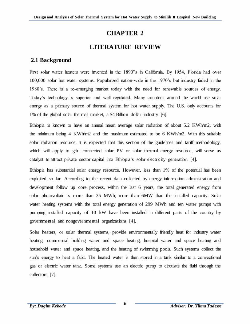
2.2.1 Flat Plate Collector
Flat-plate collectors can be designed for applications requiring energy delivery at moderate
temperatures, up to perhaps 100◦C above ambient temperature. They use both beam and diffuse
solar radiation, and do not require tracking of the sun, with little maintenance required. They are
mechanically simpler than concentrating collectors. The major applications of these units are in
solar water heating, building heating, air conditioning, and industrial process heat [8].
Figure 2.1 Typical Flat Plate Collectors
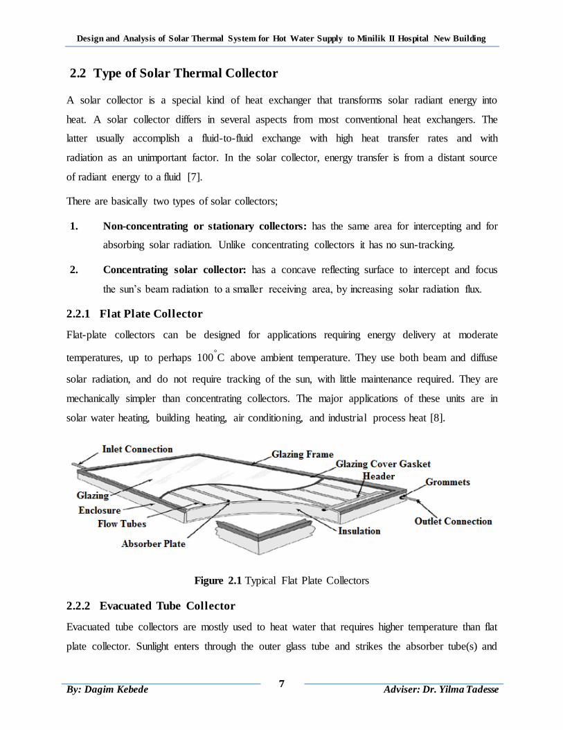
2.2.2 Evacuated Tube Collector
Evacuated tube collectors are mostly used to heat water that requires higher temperature than flat
plate collector. Sunlight enters through the outer glass tube and strikes the absorber tube(s) and
Design and Analysis of Solar Thermal System for Hot Water Supply to Minilik II Hospital New Building
8
By: Dagim Kebede
Adviser: Dr. Yilma Tadesse
changes to heat. The heat is transferred to the liquid flowing through the absorber tube.
Evacuated-tube collectors generally have a smaller solar collecting surface because this surface
must be incased by an evacuated glass tube [8].
In “flooded” evacuated-tube collectors the absorber itself forms a tube through which the heat
collection fluid is pumped and typically used in passive Thermosiphon systems.
In a “heat pipe” evacuated-tube collector, a flat absorber plate running the length of the tube
covers a heat pipe filled with a fluid that evaporates at relatively low temperatures. As the fluid is
heated, it evaporates and raises to the top of the tube to transfers the heat to water in a manifold
and condensed heat-collection fluid then return by gravity to the bottom of the heat pipe. These
systems can be active or passive [8].
Figure 2.2: Evacuated tube collector (flooded evacuated tube and heat pipe evacuated tube)
2.2.3 Concentrating Collectors
Concentrating collectors make use of curved reflectors to concentrate sunlight on a receiver. The
intensity of sunlight falling on the receiver can be up to 60 times the intensity of normal sunlight.
The parabolic reflector concentrates sunlight on a tube running along the reflector's focal line,
thereby heating the water passing through the tube. Usually, the reflector is controlled by a
tracking system that keeps the reflector facing direct sunlight throughout the day [8].

Design and Analysis of Solar Thermal System for Hot Water Supply to Minilik II Hospital New Building
9
By: Dagim Kebede
Adviser: Dr. Yilma Tadesse
In order to deliver high temperatures with good efficiency, a high performance solar collector is
required. Systems with light structures and low cost technology for process heat applications for
hot water temperatures up to 400 °C could be obtained with a type of concentrating collector
called parabolic trough collectors. PTCs can effectively produce heat at temperatures between 50
and 400 °C [8, 9].
2.3 Solar water heating system
Solar water heating systems are classified depending on how the domestic water is heated or how
the heat transfer fluid (water or antifreeze fluid) flows through the collector. Factors that
influence the selection of a specific system type include the amount of water that needs to be
heated, relative cost and efficiency, simplicity of operation, and climate conditions in which the
system will be used [9].
2.3.1 Passive Systems
In passive systems, hot water is either stored in the collector itself or is transferred to a storage
tank located above the collectors by means of a Thermosiphon. Passive systems do not employ
pumps to circulate water or collector fluid. This makes them generally more reliable, easier to
maintain, and possibly long lasting than active systems. There are two types of passive systems;
Thermosiphon systems and Integral collector storage systems [7, 8, 9].
a) Integral Collector Storage (ICS) Systems (Batch Systems)
In integral collector storage or batch systems, water is heated directly by the sun and the storage
tank serves as the solar collector. Batch water heaters are almost always passive systems in
which hot water is delivered from the solar heated tank to a backup tank or the point of use by
the water pressure in the house. Most designs use local main water pressure to circulate water in
the collector. Water may also flow due to buoyancy forces set up due to differential heating on
the collector and valves control the flow direction. Hot water is drawn from the top, which is the
hottest, and replacement water flows into the bottom. These systems are relatively cheaper than
thermosyphon systems [8, 9].
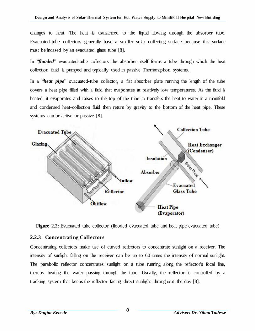
b) Thermosyphon Systems
As the sun shines on the collector, the water inside the collector flow-tubes is heated. As it heats
up, this water expands slightly and becomes lighter than the cold water in the solar storage tank
Design and Analysis of Solar Thermal System for Hot Water Supply to Minilik II Hospital New Building
10
By: Dagim Kebede
Adviser: Dr. Yilma Tadesse
mounted above the collector. Gravity then pulls heavier (cold water) down from the tank and into
the collector inlet. The cold water pushes the heated water through the collector outlet and into
the top of the tank, thus heating the water in the tank. A thermosyphon system requires neither
pump nor controller [7, 9].
Figure 2.3: Thermosyphon SWH system
2.3.2 Active Systems
Active systems use pumps, valves, and controllers to circulate water or other heat-transfer fluids
through the collectors. They are usually more expensive than passive systems but are also more
efficient. Active systems are usually easier to retrofit than passive systems because their storage
tanks do not need to be installed above or close to the collectors. But because they use electricity
for pumping, they will not function in a power outage [7, 8, 9].
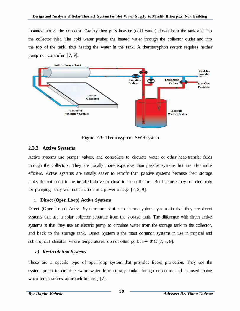
i. Direct (Open Loop) Active Systems
Direct (Open Loop) Active Systems are similar to thermosyphon systems in that they are direct
systems that use a solar collector separate from the storage tank. The difference with direct active
systems is that they use an electric pump to circulate water from the storage tank to the collector,
and back to the storage tank. Direct System is the most common systems in use in tropical and
sub-tropical climates where temperatures do not often go below 0°C [7, 8, 9].
a) Recirculation Systems
These are a specific type of open-loop system that provides freeze protection. They use the
system pump to circulate warm water from storage tanks through collectors and exposed piping
when temperatures approach freezing [7].
Design and Analysis of Solar Thermal System for Hot Water Supply to Minilik II Hospital New Building
11
By: Dagim Kebede
Adviser: Dr. Yilma Tadesse
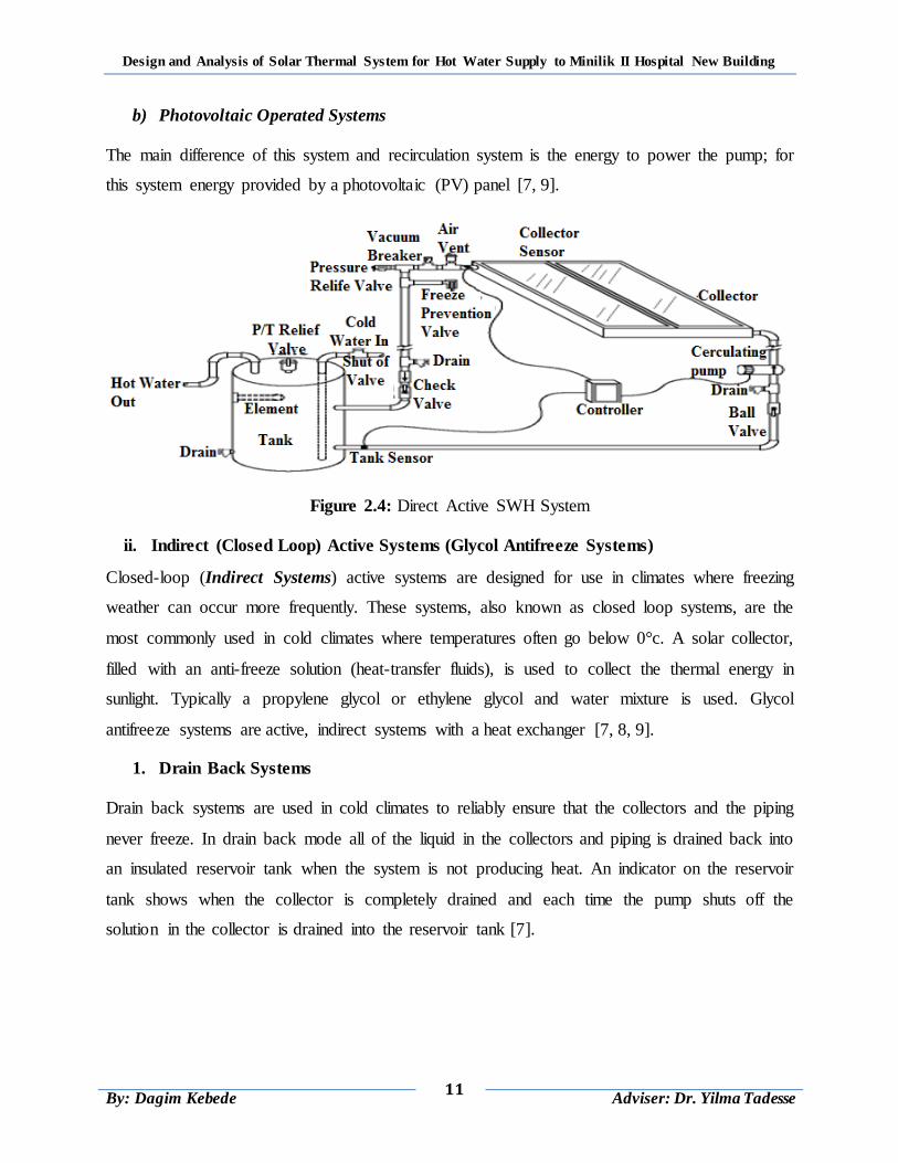
b) Photovoltaic Operated Systems
The main difference of this system and recirculation system is the energy to power the pump; for
this system energy provided by a photovoltaic (PV) panel [7, 9].
Figure 2.4: Direct Active SWH System
ii. Indirect (Closed Loop) Active Systems (Glycol Antifreeze Systems)
Closed-loop (Indirect Systems) active systems are designed for use in climates where freezing
weather can occur more frequently. These systems, also known as closed loop systems, are the
most commonly used in cold climates where temperatures often go below 0°c. A solar collector,
filled with an anti-freeze solution (heat-transfer fluids), is used to collect the thermal energy in
sunlight. Typically a propylene glycol or ethylene glycol and water mixture is used. Glycol
antifreeze systems are active, indirect systems with a heat exchanger [7, 8, 9].
1. Drain Back Systems
Drain back systems are used in cold climates to reliably ensure that the collectors and the piping
never freeze. In drain back mode all of the liquid in the collectors and piping is drained back into
an insulated reservoir tank when the system is not producing heat. An indicator on the reservoir
tank shows when the collector is completely drained and each time the pump shuts off the
solution in the collector is drained into the reservoir tank [7].
Design and Analysis of Solar Thermal System for Hot Water Supply to Minilik II Hospital New Building
12
By: Dagim Kebede
Adviser: Dr. Yilma Tadesse
2.4 Factors Affecting Solar Water Heating (SWH) Performance
The performance of a solar water heating system depends on the following factors
2.4.1 Ambient Conditions
The amount of incident radiation determines the absorbed solar radiation by the collector while
the ambient temperature determines the thermal losses from the collector. Cloudy conditions
limit the beam insolation levels and thus the radiation absorbed by the collector especially the
concentrating collectors [1, 5].
2.4.2 Collector Orientation and Tilt
Geographic orientation and collector tilt can affect the amount of solar radiation received by
system. Collector orientation is critical in achieving maximum performance from a solar energy
system. In general, the optimum orientation for a solar collector in the northern hemisphere is
true south (azimuth of 180°). However, recent studies have shown that, depending on the
location and collector tilt, the collector can face up to 90° east or west of true south without
significantly decreasing its performance [1, 5].
2.4.3 Transport Fluid Flow Rate
Low collector fluid flow rates of about ( ) increases the thermal
performance of the collector by increasing the degree of storage tank thermal stratification. In a
stratified tank, the temperature of fluid at the bottom of the storage tank is lower than at the top.
Collector inlet temperature is reduced because the collector inlet fluid is fed from the bottom
portion of the tank that reduces thermal losses and increased useful energy gain [1, 5].
2.4.4 Collector Array Arrangement
The performance of the collector array depends on how the collector modules are connected. In
parallel connection, module inlet and outlet ports are fed to the common respective headers.
Assuming identical modules, fluid inlet temperature is the same to all modules in the array and
also true to fluid outlet temperature. The performance of the collector array is thus the same as
the performance of the individual collector. Unlike parallel connection; in series connection, the
performance of the second and subsequent modules will not be the same as the first because its
inlet temperature is the outlet temperature of the first [1, 5].
Design and Analysis of Solar Thermal System for Hot Water Supply to Minilik II Hospital New Building
13
By: Dagim Kebede
Adviser: Dr. Yilma Tadesse
2.4.5 Collector Characteristics
Collector area, its absorber plate absorbents property and its glass cover optical properties affect
the amount of the incident solar irradiation that can be absorbed while collector insulation
thickness and its thermal conductivity affect the overall heat loss coefficient and thus the thermal
losses [1, 5].
2.5 Summary of Literature Review
A solar water heater is a long-term investment that will save money and energy for many years.
Like other renewable energy systems, solar water heaters minimize the environmental effects. In
addition, they provide insurance against energy price increases, help reduce our dependence on
imported oil, and are investments in everyone's future.
The proposed solar water heating system would be of the active system type where flat plate
collector thermal performance would be analyzed because it is the most used collector in Africa.
The solar collector modules would be better if identical and parallel connected so as to have the
same fluid inlet and outlet temperatures in all the modules in the array. Low inlet temperature of
a collector would be preferred, to reduce thermal losses and increase useful energy gain and
thermal performance.
Design and Analysis of Solar Thermal System for Hot Water Supply to Minilik II Hospital New Building
14
By: Dagim Kebede
Adviser: Dr. Yilma Tadesse
CHAPTER 3
HOT WATER DEMAND OF MINILIK II HOSPITAL
3.1 Introduction
Hospitals and health care buildings traditionally have high energy demands for both mechanical
power and heat. Heat is required for space heating needs, sanitary hot water, and steam
production. Among the heat required system of the hospital, water heating system is one of the
most energy extensive process. Demand for Hot water consumption in hospital is very high.
Also, because of the big size of the buildings, there is important loss of heat in the pipeline [3].
That‟s why the needs in hot water must be determined with accuracy, since they differ from one
hospital to another, in order to avoid unnecessary energy consumption for water heating. To
reduce energy use and greenhouse gas emissions by hospital facilities, the health care sector
needs energy efficient solutions operating at the lowest cost and free from environment pollution
gas emission.
Generally almost all hospitals in the world require water for different appliance that Depending
on the type and size of a facility, hospitals typically use 15% of their water for non-domestic use
(sterile processing and radiology) and 85% for domestic use including (boilers, chillers, food
services to the patient and pantry service for guests, operating rooms, laundry facilities, kitchen
equipment, sinks, tubs and showers, washing basing and toilets). Daily water demand of the
hospital about 90% is hot water and 10% is cold water application [3].
In Ethiopia most of hospitals requires hot water for the appliance including kitchen equipment
washing, laundry facilities, showering purpose, food service to the patient and hospital
restaurants, sterile processing, boilers and radiology. Few private hospitals have higher standard,
which riches to the typical standard hospital hot water demand and appliance used.
This chapter manly concentrates on hot water demand calculation of Minilik II hospital. This
hospital uses electricity as sources of energy for water heating, to meet daily hot water demand
of the hospital. The appliance considered for this study includes kitchen equipment, laundry
facilities, shower and restaurant of Minilik II hospital new building.
Design and Analysis of Solar Thermal System for Hot Water Supply to Minilik II Hospital New Building
15
By: Dagim Kebede
Adviser: Dr. Yilma Tadesse
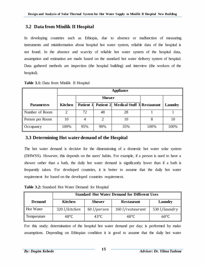
3.2 Data from Minilik II Hospital
In developing countries such as Ethiopia, due to absence or malfunction of measuring
instruments and misinformation about hospital hot water system, reliable data of the hospital is
not found. In the absence and scarcity of reliable hot water system of the hospital data,
assumption and estimation are made based on the standard hot water delivery system of hospital.
Data gathered methods are inspection (the hospital building) and interview (the workers of the
hospital).
Table 3.1: Data from Minilik II Hospital
Parameters
Appliance
Kitchen
Shower
Restaurant Laundry Patient 1 Patient 2 Medical Stuff 3
Number of Room 2 72 48 28 1 1
Person per Room 10 4 2 10 8 10
Occupancy 100% 95% 90% 35% 100% 100%
3.3 Determining Hot water demand of the Hospital
The hot water demand is decisive for the dimensioning of a domestic hot water solar system
(DHWSS). However, this depends on the users' habits. For example, if a person is used to have a
shower rather than a bath, the daily hot water demand is significantly lower than if a bath is
frequently taken. For developed countries, it is better to assume that the daily hot water
requirement for based on the developed countries requirement.
Table 3.2: Standard Hot Water Demand for Hospital
Demand
Standard Hot Water Demand for Different Uses
Kitchen Shower Restaurant Laundry
Hot Water 320 60 160 530
Temperature
For this study; determination of the hospital hot water demand per day; is performed by make
assumptions. Depending on Ethiopian condition it is good to assume that the daily hot water
Design and Analysis of Solar Thermal System for Hot Water Supply to Minilik II Hospital New Building
16
By: Dagim Kebede
Adviser: Dr. Yilma Tadesse
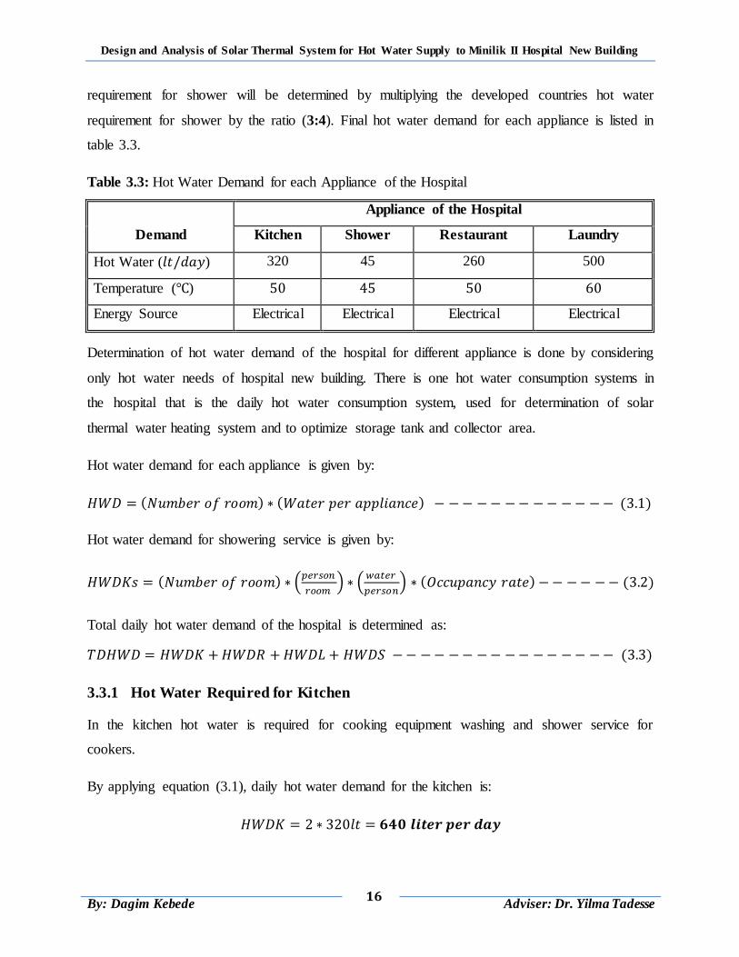
requirement for shower will be determined by multiplying the developed countries hot water
requirement for shower by the ratio (3:4). Final hot water demand for each appliance is listed in
table 3.3.
Table 3.3: Hot Water Demand for each Appliance of the Hospital
Demand
Appliance of the Hospital
Kitchen Shower Restaurant Laundry
Hot Water ( ) 320 45 260 500
Temperature ( )
Energy Source Electrical Electrical Electrical Electrical
Determination of hot water demand of the hospital for different appliance is done by considering
only hot water needs of hospital new building. There is one hot water consumption systems in
the hospital that is the daily hot water consumption system, used for determination of solar
thermal water heating system and to optimize storage tank and collector area.
Hot water demand for each appliance is given by:
( ) ( ) ( )
Hot water demand for showering service is given by:
( ) (
) (
) ( ) ( )
Total daily hot water demand of the hospital is determined as:
( )
3.3.1 Hot Water Required for Kitchen
In the kitchen hot water is required for cooking equipment washing and shower service for
cookers.
By applying equation (3.1), daily hot water demand for the kitchen is:
Design and Analysis of Solar Thermal System for Hot Water Supply to Minilik II Hospital New Building
17
By: Dagim Kebede
Adviser: Dr. Yilma Tadesse
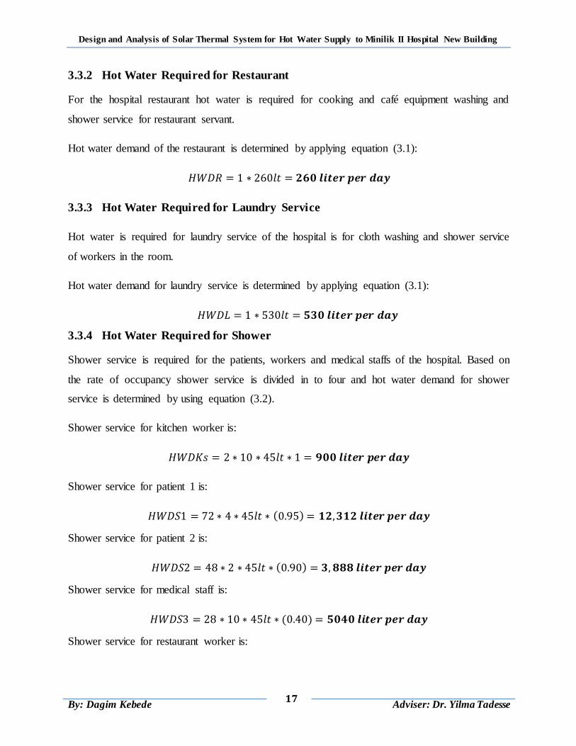
3.3.2 Hot Water Required for Restaurant
For the hospital restaurant hot water is required for cooking and café equipment washing and
shower service for restaurant servant.
Hot water demand of the restaurant is determined by applying equation (3.1):
3.3.3 Hot Water Required for Laundry Service
Hot water is required for laundry service of the hospital is for cloth washing and shower service
of workers in the room.
Hot water demand for laundry service is determined by applying equation (3.1):
3.3.4 Hot Water Required for Shower
Shower service is required for the patients, workers and medical staffs of the hospital. Based on
the rate of occupancy shower service is divided in to four and hot water demand for shower
service is determined by using equation (3.2).
Shower service for kitchen worker is:
Shower service for patient 1 is:
( )
Shower service for patient 2 is:
( )
Shower service for medical staff is:
( )
Shower service for restaurant worker is:
Design and Analysis of Solar Thermal System for Hot Water Supply to Minilik II Hospital New Building
18
By: Dagim Kebede
Adviser: Dr. Yilma Tadesse
( )
Shower service for laundry worker is:
( )
Total daily hot water demand for shower service is determined by using equation (3.3):
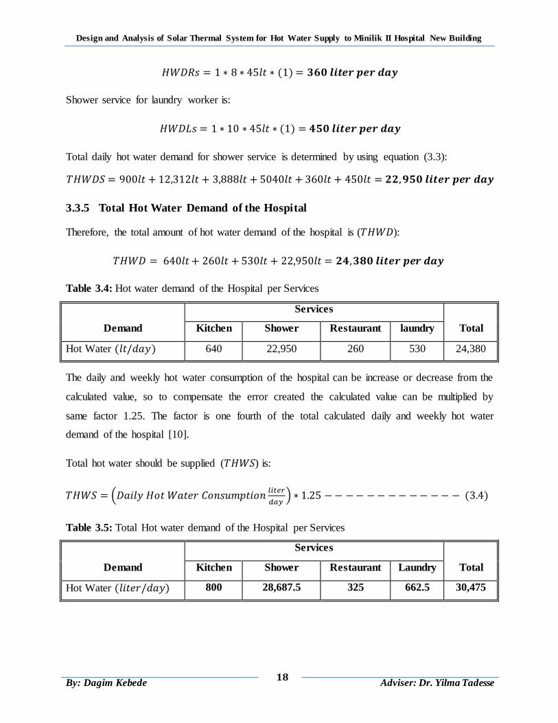
3.3.5 Total Hot Water Demand of the Hospital
Therefore, the total amount of hot water demand of the hospital is ( ):
Table 3.4: Hot water demand of the Hospital per Services
Demand
Services
Total Kitchen Shower Restaurant laundry
Hot Water ( ) 640 22,950 260 530 24,380
The daily and weekly hot water consumption of the hospital can be increase or decrease from the
calculated value, so to compensate the error created the calculated value can be multiplied by
same factor 1.25. The factor is one fourth of the total calculated daily and weekly hot water
demand of the hospital [10].
Total hot water should be supplied ( ) is:
(
) ( )
Table 3.5: Total Hot water demand of the Hospital per Services
Demand
Services
Total Kitchen Shower Restaurant Laundry
Hot Water ( ) 800 28,687.5 325 662.5 30,475
Design and Analysis of Solar Thermal System for Hot Water Supply to Minilik II Hospital New Building
19
By: Dagim Kebede
Adviser: Dr. Yilma Tadesse
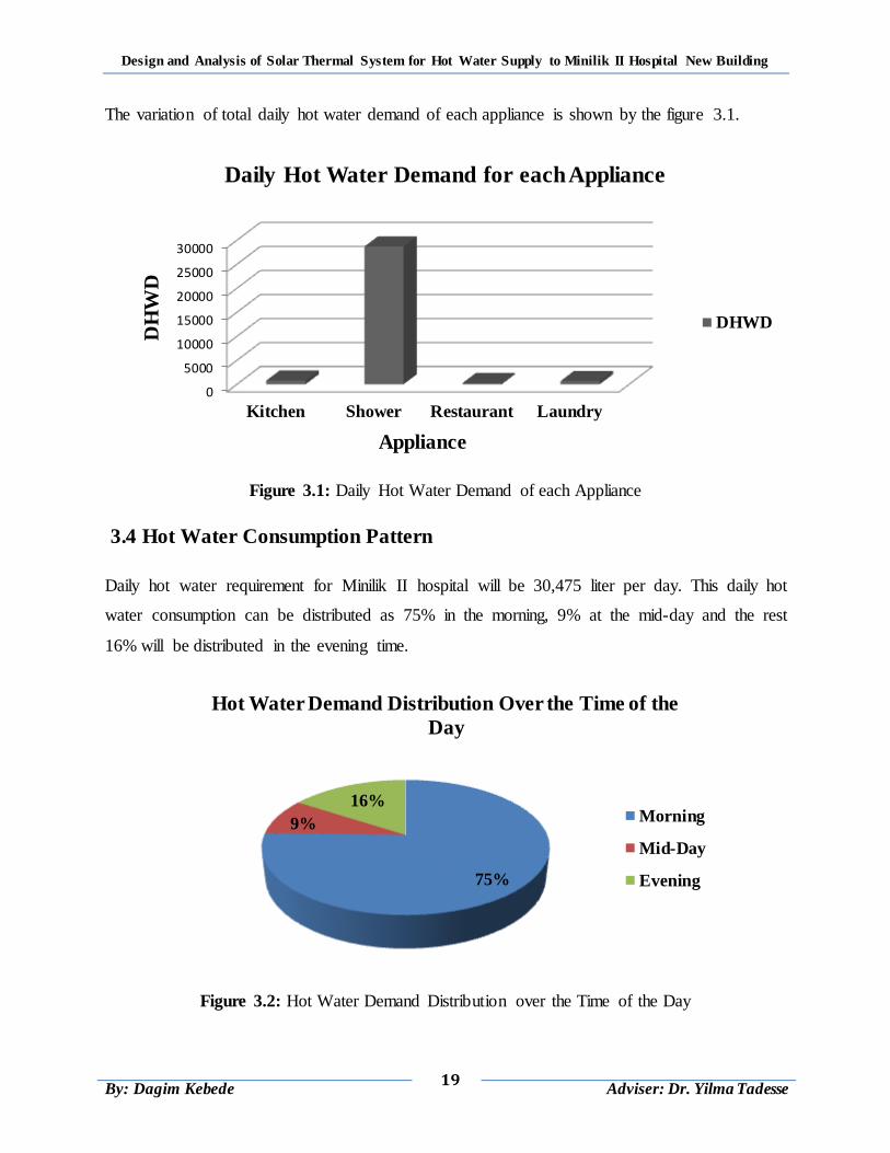
The variation of total daily hot water demand of each appliance is shown by the figure 3.1.
Figure 3.1: Daily Hot Water Demand of each Appliance
3.4 Hot Water Consumption Pattern
Daily hot water requirement for Minilik II hospital will be 30,475 liter per day. This daily hot
water consumption can be distributed as 75% in the morning, 9% at the mid-day and the rest
16% will be distributed in the evening time.
Figure 3.2: Hot Water Demand Distribution over the Time of the Day
0
5000
10000
15000
20000
25000
30000
Kitchen Shower Restaurant Laundry
DH
WD
Appliance
Daily Hot Water Demand for each Appliance
DHWD
75%
9%
16%
Hot Water Demand Distribution Over the Time of the
Day
Morning
Mid-Day
Evening
Design and Analysis of Solar Thermal System for Hot Water Supply to Minilik II Hospital New Building
20
By: Dagim Kebede
Adviser: Dr. Yilma Tadesse
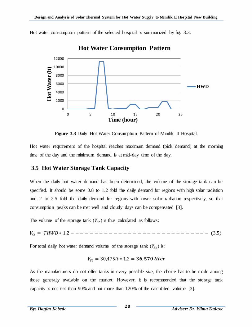
Hot water consumption pattern of the selected hospital is summarized by fig. 3.3.
Figure 3.3 Daily Hot Water Consumption Pattern of Minilik II Hospital.
Hot water requirement of the hospital reaches maximum demand (pick demand) at the morning
time of the day and the minimum demand is at mid-day time of the day.
3.5 Hot Water Storage Tank Capacity
When the daily hot water demand has been determined, the volume of the storage tank can be
specified. It should be some 0.8 to 1.2 fold the daily demand for regions with high solar radiation
and 2 to 2.5 fold the daily demand for regions with lower solar radiation respectively, so that
consumption peaks can be met well and cloudy days can be compensated [3].
The volume of the storage tank ( ) is thus calculated as follows:
( )
For total daily hot water demand volume of the storage tank ( ) is:
As the manufacturers do not offer tanks in every possible size, the choice has to be made among
those generally available on the market. However, it is recommended that the storage tank
capacity is not less than 90% and not more than 120% of the calculated volume [3].
0
2000
4000
6000
8000
10000
12000
0 5 10 15 20 25
Ho
t W
ate
r (l
t)
Time (hour)
Hot Water Consumption Pattern
HWD
Design and Analysis of Solar Thermal System for Hot Water Supply to Minilik II Hospital New Building
21
By: Dagim Kebede
Adviser: Dr. Yilma Tadesse
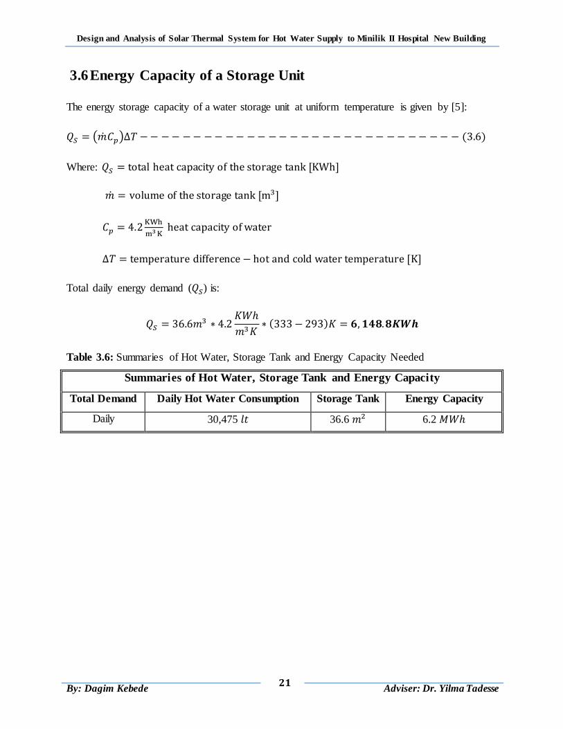
3.6 Energy Capacity of a Storage Unit
The energy storage capacity of a water storage unit at uniform temperature is given by [5]:
( ) ( )
Where:
Total daily energy demand ( ) is:
( )
Table 3.6: Summaries of Hot Water, Storage Tank and Energy Capacity Needed
Summaries of Hot Water, Storage Tank and Energy Capacity
Total Demand Daily Hot Water Consumption Storage Tank Energy Capacity
Daily 30,475 36.6 6.2
Design and Analysis of Solar Thermal System for Hot Water Supply to Minilik II Hospital New Building
22
By: Dagim Kebede
Adviser: Dr. Yilma Tadesse
CHAPTER 4
AVAILABLE SOLAR RADIATION DATA
4.1 Introduction
Solar power is the flow of energy from the sun. The primary forms of solar energy are heat and
light. Sunlight and heat are transformed and absorbed by the environment in a multitude of ways.
Some of these transformations result in renewable energy flows such as biomass, wind and
waves. Effects such as the jet stream, the Gulf Stream and the water cycle are also the result of
solar energy's absorption in the environment [5].
Interest in solar energy has prompted the accurate measurement and mapping of solar energy
resources of the globe. Solar radiation data are available in several forms. Most radiation data
available for horizontal surfaces include both direct and diffuse radiation. This is normally done
by using solar-meters. Most solar-meters measurements are recorded simply as total energy
(global radiation) incident on the horizontal surface; other measurements separate the direct
(beam) and the scattered (diffuse) radiation.
Radiation data are the best source of information for estimating average incident radiation and
for the proper designing of a solar water heating system. A precise analysis and design of a solar
water heating system requires knowledge of the solar thermal system, the availability of global
solar radiation and its components at the location of project site. Since the solar radiation
reaching the earth‟s surface depends upon climatic conditions of the place, a study of solar
radiation under local climatic conditions is essential [5, 10].
Due to absence or malfunction of measuring instruments, reliable solar radiation data is not
available. In the absence and scarcity of trustworthy solar radiation data, the use of an empirical
model to predict and estimate solar radiation seems inevitable. This study uses data of solar
radiation and ambient temperature from Ethiopian metrological agency for the project location
(around Minilik II hospital). Solar radiation data available in Ethiopian metrological agency is
only global radiation. Beam and diffuse solar radiation data calculated by using solar energy
empirical relations, available global radiation data at project site, location (latitude and
longitude) of Minilik II hospital and weather condition of the area.
Design and Analysis of Solar Thermal System for Hot Water Supply to Minilik II Hospital New Building
23
By: Dagim Kebede
Adviser: Dr. Yilma Tadesse
4.2 Incident Solar Radiation
The solar radiation energy incident on the collector surface which is inclined at an angle of ( ) to
the horizontal surface is defined in terms of global, diffuse, beam and reflectivity radiation. Total
solar radiation incident on a surface consists of beam, diffuse and reflected solar radiation from
the ground and surrounding. Total radiation on a surface can be evaluated by arbitrary
orientation from knowledge of beam, diffuse and global radiation on horizontal surface [5].
The total incident radiation on this surface can be written as:
( )
The flux incident beam radiation collected by the absorber per unit time is given by:
( ) ( )
4.2.1 Global Radiation ( )
Global solar radiation is the sum of the beam and the diffuse solar radiation on a surface (the
most common measurements of solar radiation are total radiation on a horizontal surface, often
referred to as global radiation on the surface.
Available global radiation on a given area can be determined in two ways:
First one is estimating the radiation data using solar energy empirically relations and
Second one is measuring the radiation data by using solar-meters instrument called
pyranometers, that most of available solar radiation data are obtained.
Generally for this study, analysis of available temperature at project location to heat water uses
measured global radiation by Ethiopian metrology agency. Global radiation data gained from
metrological agency is read from automatic station within 15 minutes.
a) Average Monthly Global Radiation
The monthly average global radiation on a horizontal surface can be calculated from the
meteorological data of hourly and daily global radiation on a horizontal surface and global
radiation on an inclined surface is determined multiplying global radiation on horizontal surface
by same angle ( ). Average monthly global radiation of project site gained from metrological for
6 year (2010-2015) is given in the table 4.1.
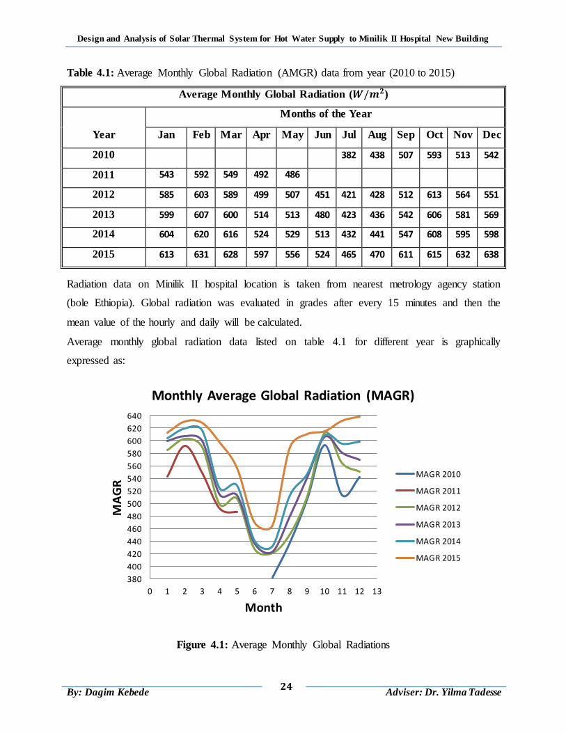
Design and Analysis of Solar Thermal System for Hot Water Supply to Minilik II Hospital New Building
24
By: Dagim Kebede
Adviser: Dr. Yilma Tadesse
Table 4.1: Average Monthly Global Radiation (AMGR) data from year (2010 to 2015)
Average Monthly Global Radiation ( )
Year
Months of the Year
Jan Feb Mar Apr May Jun Jul Aug Sep Oct Nov Dec
2010 382 438 507 593 513 542
2011 543 592 549 492 486
2012 585 603 589 499 507 451 421 428 512 613 564 551
2013 599 607 600 514 513 480 423 436 542 606 581 569
2014 604 620 616 524 529 513 432 441 547 608 595 598
2015 613 631 628 597 556 524 465 470 611 615 632 638
Radiation data on Minilik II hospital location is taken from nearest metrology agency station
(bole Ethiopia). Global radiation was evaluated in grades after every 15 minutes and then the
mean value of the hourly and daily will be calculated.
Average monthly global radiation data listed on table 4.1 for different year is graphically
expressed as:
Figure 4.1: Average Monthly Global Radiations
380
400
420
440
460
480
500
520
540
560
580
600
620
640
0 1 2 3 4 5 6 7 8 9 10 11 12 13
MA
GR
Month
Monthly Average Global Radiation (MAGR)
MAGR 2010
MAGR 2011
MAGR 2012
MAGR 2013
MAGR 2014
MAGR 2015
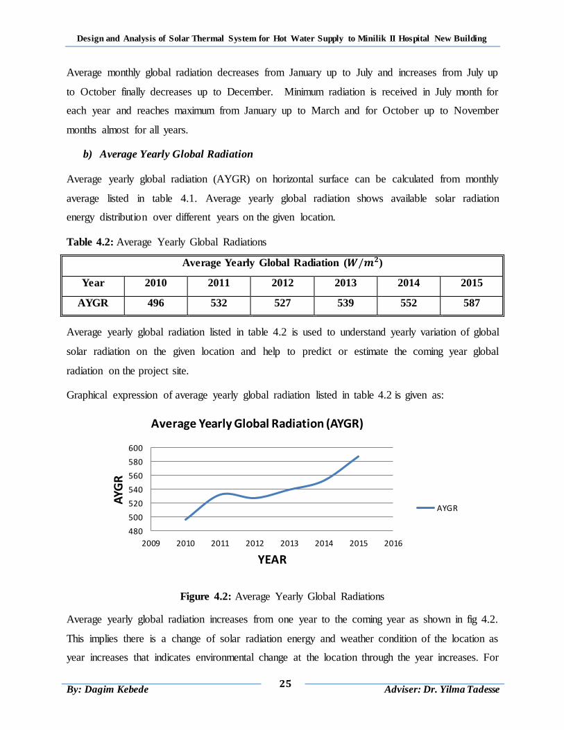
Design and Analysis of Solar Thermal System for Hot Water Supply to Minilik II Hospital New Building
25
By: Dagim Kebede
Adviser: Dr. Yilma Tadesse
Average monthly global radiation decreases from January up to July and increases from July up
to October finally decreases up to December. Minimum radiation is received in July month for
each year and reaches maximum from January up to March and for October up to November
months almost for all years.
b) Average Yearly Global Radiation
Average yearly global radiation (AYGR) on horizontal surface can be calculated from monthly
average listed in table 4.1. Average yearly global radiation shows available solar radiation
energy distribution over different years on the given location.
Table 4.2: Average Yearly Global Radiations
Average Yearly Global Radiation ( )
Year 2010 2011 2012 2013 2014 2015
AYGR 496 532 527 539 552 587
Average yearly global radiation listed in table 4.2 is used to understand yearly variation of global
solar radiation on the given location and help to predict or estimate the coming year global
radiation on the project site.
Graphical expression of average yearly global radiation listed in table 4.2 is given as:
Figure 4.2: Average Yearly Global Radiations
Average yearly global radiation increases from one year to the coming year as shown in fig 4.2.
This implies there is a change of solar radiation energy and weather condition of the location as
year increases that indicates environmental change at the location through the year increases. For
480
500
520
540
560
580
600
2009 2010 2011 2012 2013 2014 2015 2016
AYG
R
YEAR
Average Yearly Global Radiation (AYGR)
AYGR
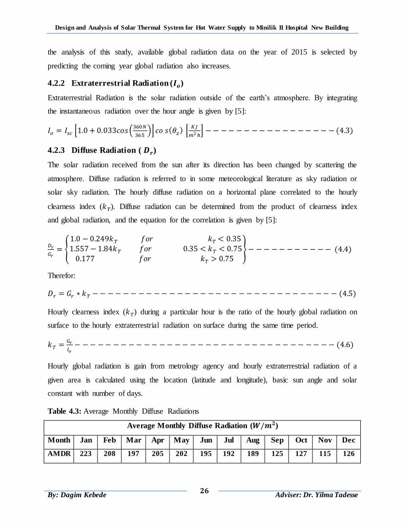
Design and Analysis of Solar Thermal System for Hot Water Supply to Minilik II Hospital New Building
26
By: Dagim Kebede
Adviser: Dr. Yilma Tadesse
the analysis of this study, available global radiation data on the year of 2015 is selected by
predicting the coming year global radiation also increases.
4.2.2 Extraterrestrial Radiation ( )
Extraterrestrial Radiation is the solar radiation outside of the earth‟s atmosphere. By integrating
the instantaneous radiation over the hour angle is given by [5]:
* (
)+ ( ) *
+ ( )
4.2.3 Diffuse Radiation ( )
The solar radiation received from the sun after its direction has been changed by scattering the
atmosphere. Diffuse radiation is referred to in some meteorological literature as sky radiation or
solar sky radiation. The hourly diffuse radiation on a horizontal plane correlated to the hourly
clearness index ( ). Diffuse radiation can be determined from the product of clearness index
and global radiation, and the equation for the correlation is given by [5]:
{
} ( )
Therefor:
( )
Hourly clearness index ( ) during a particular hour is the ratio of the hourly global radiation on
surface to the hourly extraterrestrial radiation on surface during the same time period.
( )
Hourly global radiation is gain from metrology agency and hourly extraterrestrial radiation of a
given area is calculated using the location (latitude and longitude), basic sun angle and solar
constant with number of days.
Table 4.3: Average Monthly Diffuse Radiations
Average Monthly Diffuse Radiation ( )
Month Jan Feb Mar Apr May Jun Jul Aug Sep Oct Nov Dec
AMDR 223 208 197 205 202 195 192 189 125 127 115 126
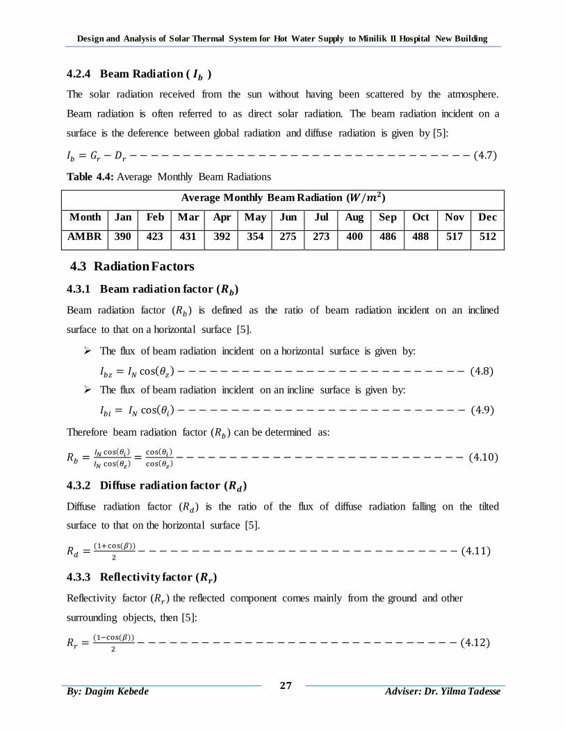
Design and Analysis of Solar Thermal System for Hot Water Supply to Minilik II Hospital New Building
27
By: Dagim Kebede
Adviser: Dr. Yilma Tadesse
4.2.4 Beam Radiation ( )
The solar radiation received from the sun without having been scattered by the atmosphere.
Beam radiation is often referred to as direct solar radiation. The beam radiation incident on a
surface is the deference between global radiation and diffuse radiation is given by [5]:
( )
Table 4.4: Average Monthly Beam Radiations
Average Monthly Beam Radiation ( )
Month Jan Feb Mar Apr May Jun Jul Aug Sep Oct Nov Dec
AMBR 390 423 431 392 354 275 273 400 486 488 517 512
4.3 Radiation Factors
4.3.1 Beam radiation factor ( )
Beam radiation factor ( ) is defined as the ratio of beam radiation incident on an inclined
surface to that on a horizontal surface [5].
The flux of beam radiation incident on a horizontal surface is given by:
( ) ( )
The flux of beam radiation incident on an incline surface is given by:
( ) ( )
Therefore beam radiation factor ( ) can be determined as:
( )
( )
( )
( ) ( )
4.3.2 Diffuse radiation factor ( )
Diffuse radiation factor ( ) is the ratio of the flux of diffuse radiation falling on the tilted
surface to that on the horizontal surface [5].
( ( ))
( )
4.3.3 Reflectivity factor ( )
Reflectivity factor ( ) the reflected component comes mainly from the ground and other
surrounding objects, then [5]:
( ( ))
( )
Design and Analysis of Solar Thermal System for Hot Water Supply to Minilik II Hospital New Building
28
By: Dagim Kebede
Adviser: Dr. Yilma Tadesse
4.4 Basic Sun-Earth Angles
The position of a location on the earth‟s surface is defined by the coordinate‟s latitude and
meridian or longitude angles. Depending on the orientation of the inclined surface, the
expression for ( ) and ( ) can be obtained as:
4.4.1 Angle of incidence( )
Angle of incidence is the angle between the beam radiation on a surface and the line normal to
surface [5].
( ) ( ( ) ( ) ( ) ( )) ( ) ( ) ( )(( ( ) ( )
( ( ) ( ))) ( )
4.4.2 Zenith angle( )
Zenith angle is the angle between the sun‟s ray and the perpendicular line to a horizontal plane
[5].
( ) ( ) ( ) ( ) ( ) ( ) ( )
Where: latitude ( ), collector tilte ( ), declination ( ) and hour ( ) angles
4.4.3 Latitude ( )
The latitude of a location is the angle made by the radial line joining the given location to the
center of the earth with its projection on the equatorial plane. The project site Minilik II hospital
is located on:
Therefore the latitude angle is positive.
4.4.4 Hour angle ( )
The hour angle of a point on the earth‟s surface is defined as the angle through which the earth
would turn to bring the meridian of the point directly under the sun. Hour angle and solar time in
hour are related as [5]:
( ) ( )
Where: ST = is solar time (from1 to 24) hours.
Design and Analysis of Solar Thermal System for Hot Water Supply to Minilik II Hospital New Building
29
By: Dagim Kebede
Adviser: Dr. Yilma Tadesse
4.4.5 Declination angle ( )
Declination angle is the angle between the earth‟s equatorial plane and the line drawn between
the center of the earth and the sun. Declination angle of the sun varies daily and is calculated
from the following relation [5]:
*
( )+ ( )
4.4.6 Collector Tilt
The tilt of a collector is the angle between the collector and the local horizontal. In most solar
water heating applications, a tilt of approximately latitude plus 10º to 15º is near optimum
because it is necessary to favor the summer season, when the collector operates under adverse
conditions (due to lower ambient temperature) and load is greatest [8].
( )
For Addis Ababa latitude ( ), the collector tilt is:
4.4.7 Collector Azimuth
The azimuth is the angle the collector faces relative to south. The maximum heating performance
is occurred at azimuth of 0º [5, 8].
4.4.8 Altitude Angle
Altitude angle is known as sun rays angle and given by [8]:
( )
Design and Analysis of Solar Thermal System for Hot Water Supply to Minilik II Hospital New Building
30
By: Dagim Kebede
Adviser: Dr. Yilma Tadesse
CHAPTER 5
FLAT PLATE COLLECTOR DESIGN
5.1 Introduction
Many of the systems, which utilize solar energy, first collected the energy as heat and converting
the radiation to thermal energy then transfers this heat to a working fluid. It must be converted to
heat before it can be used in practical heating and cooling systems. Solar energy collectors are
the device used to convert the sun‟s radiation to heat, usually consist of a surface that efficiently
absorbs radiation and converts this incident flux to heat which raises the temperature of the
absorbing material. Part of this energy is then removed from the absorbing surface by means of a
heat transfer fluid that may be either liquid or gaseous [5].
The underside of the absorber plate and the side of casing are well insulated to reduce conduction
losses. The liquid tubes can be welded to the absorbing plate, or they can be an integral part of
the plate. The liquid tubes are connected at both ends by large diameter header tubes. Since the
absorber plate has a temperature greater than its environment, unrecoverable heat losses occur
from the entire absorbing surface of the collector to the environment. Consequently, 100%
collector efficiency cannot be realized in practice [5].
This chapter deals about the designing of flat plate collector which fulfill the hot water demined
of Minilik II hospital. The design concerns; optimization of collector based on cost of
manufacturing, efficiency of collector, outlet temperature of water, weather condition and
location of project site, properties of selected material and area of the building roof for the
installation is essential. Each component of the collector design perfectly for higher efficiency
and component material is selected to receive higher solar energy and to minimize the initial cost
of the whole system.
5.2 Component of Flat Plate Collector
The components of a solar collector that enhances heat transfer are;
Glazing: One or more sheets of glass (radiation-transmitting) material.
Tubes: To conduct or direct the heat transfer fluid from the inlet to the outlet.
Absorber plates: Flat, corrugated, or grooved plates, integral with the tubes.
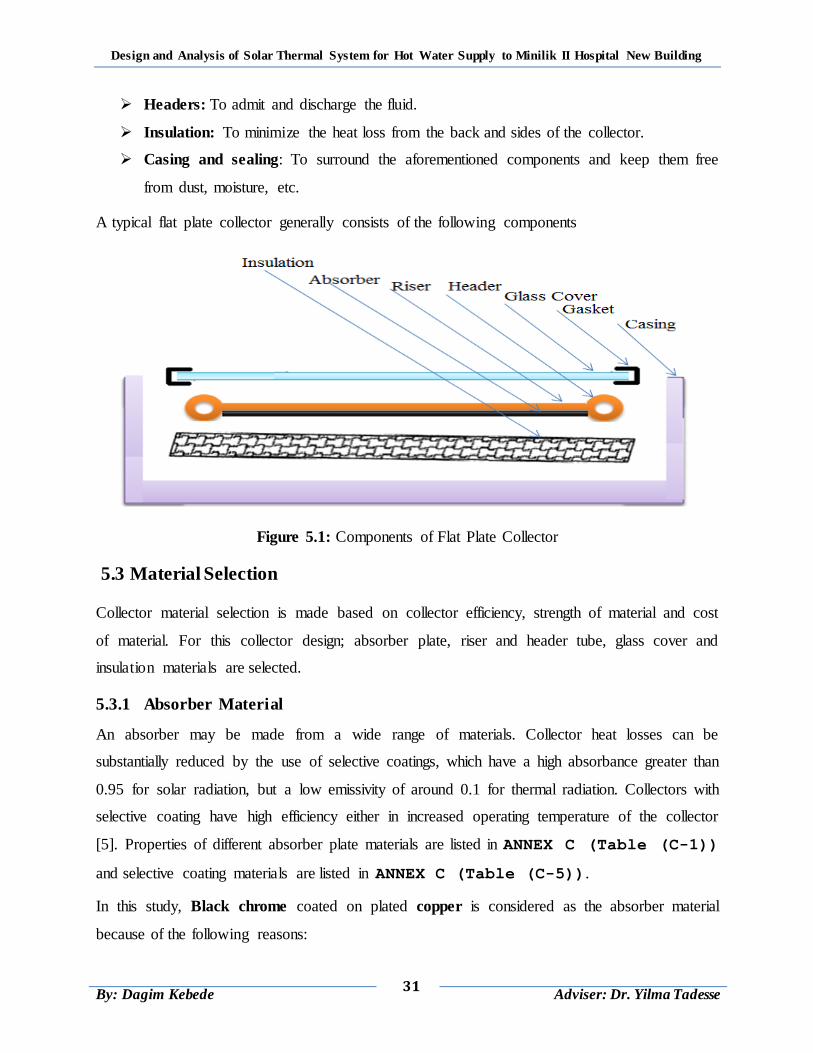
Design and Analysis of Solar Thermal System for Hot Water Supply to Minilik II Hospital New Building
31
By: Dagim Kebede
Adviser: Dr. Yilma Tadesse
Headers: To admit and discharge the fluid.
Insulation: To minimize the heat loss from the back and sides of the collector.
Casing and sealing: To surround the aforementioned components and keep them free
from dust, moisture, etc.
A typical flat plate collector generally consists of the following components
Figure 5.1: Components of Flat Plate Collector
5.3 Material Selection
Collector material selection is made based on collector efficiency, strength of material and cost
of material. For this collector design; absorber plate, riser and header tube, glass cover and
insulation materials are selected.
5.3.1 Absorber Material
An absorber may be made from a wide range of materials. Collector heat losses can be
substantially reduced by the use of selective coatings, which have a high absorbance greater than
0.95 for solar radiation, but a low emissivity of around 0.1 for thermal radiation. Collectors with
selective coating have high efficiency either in increased operating temperature of the collector
[5]. Properties of different absorber plate materials are listed in ANNEX C (Table (C-1))
and selective coating materials are listed in ANNEX C (Table (C-5)).
In this study, Black chrome coated on plated copper is considered as the absorber material
because of the following reasons:
Design and Analysis of Solar Thermal System for Hot Water Supply to Minilik II Hospital New Building
32
By: Dagim Kebede
Adviser: Dr. Yilma Tadesse
Due to its high thermal conductivity.
higher absorbance
low emissivity of the material
Has lower cost per heat energy transfer rate
High thermal and corrosion resistance and
High durability and strength.
5.3.2 Riser and Header Tube Material
Copper tubes are the most common material used for the fluid passageways, while mild steel or
stainless steel and mild steel tubes are also in use. Tubes are bonded to an absorbing plate with
high accuracy to increase system smoothness and efficiency of collector. For riser and header
tubes; selected material should be have high heat transfer rate [9]. Properties of different riser
and header tube materials are listed in ANNEX C (Table (C-1)).
For this design, copper is considered as fluid passageways tube (riser and header tube) material
because of the following reasons:
Its higher thermal conductivity.
High absorbance of material
Low emissivity of material
Suitability to high temperatures
long life
Higher corrosion resistant
High durability and strength.
Lower cost per the rate of heat energy transfer
5.3.3 Glass Cover Material
The most widely used transparent cover material in solar collectors is the common glass, which
has most of the required properties. From the standpoint of the utilization of solar energy, the
important characteristics are reflection (ρ), absorption (α), and transmission (τ). The first two
should be as low as possible and the latter as high as possible for maximum efficiency [8].
Properties of different glass cover materials are listed in ANNEX C (Table (C-2)).
In this study, Low iron, tempered glass is selected for the following reasons:
Design and Analysis of Solar Thermal System for Hot Water Supply to Minilik II Hospital New Building
33
By: Dagim Kebede
Adviser: Dr. Yilma Tadesse
mechanical strength: (it has higher mechanical strength (lower failure rates) than the
common glass)
for safety : (tempered glass breaks into a large number of relatively harmless bits of glass
and so it is safer during its use)
for higher collector efficiency: (It has higher transmittance to the solar energy)
It is readily available everywhere and its cost is reasonable
5.3.4 Insulation Material
Heat losses from the back and sides of a collector are reduced by the use of insulation. It should
be resistant to the maximum stagnation temperature of the collector usually about 150°C in
collectors with matt black paint absorbers and about 200°C when selectively coated absorbers
are used [9]. Properties of different insulation materials are listed in ANNEX C Table (C-4).
Rockwool insulation material is selected for the following reasons:
higher resistance to the water
Low thermal conductivity properties
Higher durability in the presence of moisture.
Higher thermal resistance
Because of the risks of water penetration in solar collectors
5.4 Assumption for Design
Different assumptions are made for the designing of the collector which is [5]:
Steady state system
Unit area of absorber plate
50% efficiency of the system
600C outlet water temperature
200C daily average water inlet temperature
1000C absorber plate temperature
Average daily solar radiation from metrology agency
Specific heating capacity of water
Over all heat transfer coefficient
Ambient air temperature from metrology agency
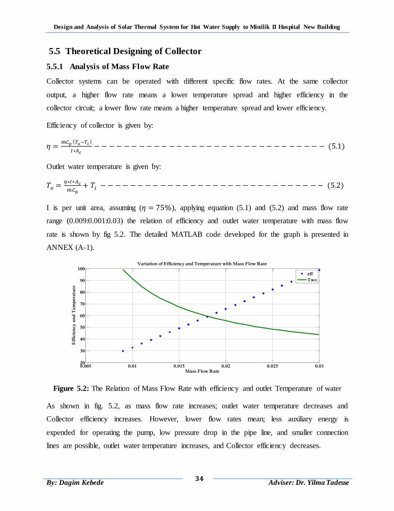
Design and Analysis of Solar Thermal System for Hot Water Supply to Minilik II Hospital New Building
34
By: Dagim Kebede
Adviser: Dr. Yilma Tadesse
5.5 Theoretical Designing of Collector
5.5.1 Analysis of Mass Flow Rate
Collector systems can be operated with different specific flow rates. At the same collector
output, a higher flow rate means a lower temperature spread and higher efficiency in the
collector circuit; a lower flow rate means a higher temperature spread and lower efficiency.
Efficiency of collector is given by:
( )
( )
Outlet water temperature is given by:
( )
I is per unit area, assuming ( ), applying equation (5.1) and (5.2) and mass flow rate
range (0.009:0.001:0.03) the relation of efficiency and outlet water temperature with mass flow
rate is shown by fig 5.2. The detailed MATLAB code developed for the graph is presented in
ANNEX (A-1).
Figure 5.2: The Relation of Mass Flow Rate with efficiency and outlet Temperature of water
As shown in fig. 5.2, as mass flow rate increases; outlet water temperature decreases and
Collector efficiency increases. However, lower flow rates mean; less auxiliary energy is
expended for operating the pump, low pressure drop in the pipe line, and smaller connection
lines are possible, outlet water temperature increases, and Collector efficiency decreases.
0.005 0.01 0.015 0.02 0.025 0.0320
30
40
50
60
70
80
90
100
Mass Flow Rate
Eff
icie
ncy
an
d T
em
pera
ture
Variation of Efficiency and Temperature with Mass Flow Rate
eff
Two
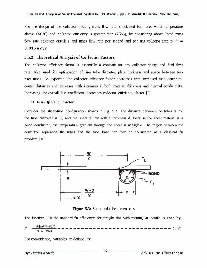
Design and Analysis of Solar Thermal System for Hot Water Supply to Minilik II Hospital New Building
35
By: Dagim Kebede
Adviser: Dr. Yilma Tadesse
For the design of the collector system, mass flow rate is selected for outlet water temperature
above ( ) and collector efficiency is greater than ( ), by considering above listed mass
flow rate selection criteria‟s and mass flow rate per second and per unit collector area is
5.5.2 Theoretical Analysis of Collector Factors
The collector efficiency factor is essentially a constant for any collector design and fluid flow
rate. Also used for optimization of riser tube diameter, plate thickness and space between two
riser tubes. As expected, the collector efficiency factor decreases with increased tube center-to-
center distances and increases with increases in both material thickness and thermal conductivity.
Increasing the overall loss coefficient decreases collector efficiency factor [5].
a) Fin Efficiency Factor
Consider the sheet-tube configuration shown in Fig. 5.3. The distance between the tubes is W,
the tube diameter is D, and the sheet is thin with a thickness δ. Because the sheet material is a
good conductor, the temperature gradient through the sheet is negligible. The region between the
centerline separating the tubes and the tube base can then be considered as a classical fin
problem [10].
Figure 5.3: Sheet and tube dimensions
The function F is the standard fin efficiency for straight fins with rectangular profile is given by:
( )
( ) ( )
For convenience, variables m defined as:
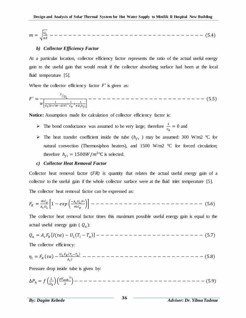
Design and Analysis of Solar Thermal System for Hot Water Supply to Minilik II Hospital New Building
36
By: Dagim Kebede
Adviser: Dr. Yilma Tadesse
√
( )
b) Collector Efficiency Factor
At a particular location, collector efficiency factor represents the ratio of the actual useful energy
gain to the useful gain that would result if the collector absorbing surface had been at the local
fluid temperature [5].
Where the collector efficiency factor is given as:
⁄
0
( )
1
( )
Notice: Assumption made for calculation of collector efficiency factor is:
The bond conductance was assumed to be very large; therefore
and
The heat transfer coefficient inside the tube ( ) may be assumed: 300 W/m2 ºC for
natural convection (Thermosiphon heaters), and 1500 W/m2 ºC for forced circulation;
therefore is selected.
c) Collector Heat Removal Factor
Collector heat removal factor (FR) is quantity that relates the actual useful energy gain of a
collector to the useful gain if the whole collector surface were at the fluid inlet temperature [5].
The collector heat removal factor can be expressed as:
[ (
)] ( )
The collector heat removal factor times this maximum possible useful energy gain is equal to the
actual useful energy gain ( ):
( ) ( ) ( )
The collector efficiency:
( ) ( )
( )
Pressure drop inside tube is given by:
(
)(
) ( )
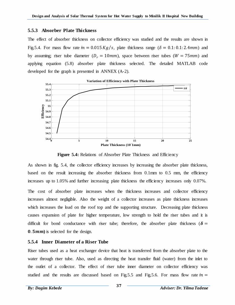
Design and Analysis of Solar Thermal System for Hot Water Supply to Minilik II Hospital New Building
37
By: Dagim Kebede
Adviser: Dr. Yilma Tadesse
5.5.3 Absorber Plate Thickness
The effect of absorber thickness on collector efficiency was studied and the results are shown in
Fig.5.4. For mass flow rate ⁄ , plate thickness range ( ) and
by assuming; riser tube diameter ( ), space between riser tubes ( ) and
applying equation (5.8) absorber plate thickness selected. The detailed MATLAB code
developed for the graph is presented in ANNEX (A-2).
Figure 5.4: Relations of Absorber Plate Thickness and Efficiency
As shown in fig. 5.4, the collector efficiency increases by increasing the absorber plate thickness,
based on the result increasing the absorber thickness from 0.1mm to 0.5 mm, the efficiency
increases up to 1.05% and further increasing plate thickness the efficiency increases only 0.07%.
The cost of absorber plate increases when the thickness increases and collector efficiency
increases almost negligible. Also the weight of a collector increases as plate thickness increases
which increases the load on the roof top and the supporting structure. Decreasing plate thickness
causes expansion of plate for higher temperature, low strength to hold the riser tubes and it is
difficult for bond conductance with riser tube; therefore, the absorber plate thickness (
) is selected for the design.
5.5.4 Inner Diameter of a Riser Tube
Riser tubes used as a heat exchanger device that heat is transferred from the absorber plate to the
water through riser tube. Also, used as directing the heat transfer fluid (water) from the inlet to
the outlet of a collector. The effect of riser tube inner diameter on collector efficiency was
studied and the results are discussed based on Fig.5.5 and Fig.5.6. For mass flow rate
0 5 10 15 20 2554.4
54.5
54.6
54.7
54.8
54.9
55
55.1
55.2
55.3
55.4
Plate Thickness (10-1mm)
Eff
icie
ncy
Variation of Efficiency with Plate Thickness
Eff
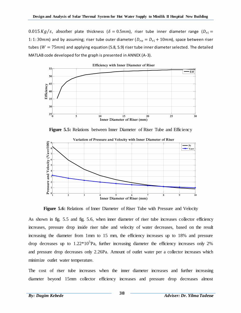
Design and Analysis of Solar Thermal System for Hot Water Supply to Minilik II Hospital New Building
38
By: Dagim Kebede
Adviser: Dr. Yilma Tadesse
⁄ , absorber plate thickness ( ), riser tube inner diameter range (
) and by assuming; riser tube outer diameter ( ), space between riser
tubes ( ) and applying equation (5.8, 5.9) riser tube inner diameter selected. The detailed
MATLAB code developed for the graph is presented in ANNEX (A-3).
Figure 5.5: Relations between Inner Diameter of Riser Tube and Efficiency
Figure 5.6: Relations of Inner Diameter of Riser Tube with Pressure and Velocity
As shown in fig. 5.5 and fig. 5.6, when inner diameter of riser tube increases collector efficiency
increases, pressure drop inside riser tube and velocity of water decreases, based on the result
increasing the diameter from 1mm to 15 mm, the efficiency increases up to 18% and pressure
drop decreases up to 1.22*105Pa, further increasing diameter the efficiency increases only 2%
and pressure drop decreases only 2.26Pa. Amount of outlet water per a collector increases which
minimize outlet water temperature.
The cost of riser tube increases when the inner diameter increases and further increasing
diameter beyond 15mm collector efficiency increases and pressure drop decreases almost
0 5 10 15 20 25 3025
30
35
40
45
50
55
Inner Diameter of Riser (mm)
Eff
icie
ncy
Efficiency with Inner Diameter of Riser
Eff
1 2 3 4 5 6 7 8 9 100
1
2
3
4
5
6
7
8
9
Inner Diameter of Riser (mm)
Pre
ssu
re a
nd
Velo
cit
y (
Va
vr/
10
0) Variation of Pressure and Velocity with Inner Diameter of Riser
Pr
Vavr
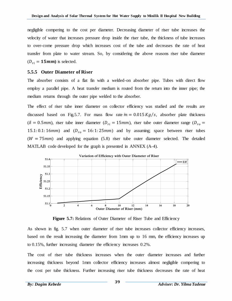
Design and Analysis of Solar Thermal System for Hot Water Supply to Minilik II Hospital New Building
39
By: Dagim Kebede
Adviser: Dr. Yilma Tadesse
negligible compering to the cost per diameter. Decreasing diameter of riser tube increases the
velocity of water that increases pressure drop inside the riser tube, the thickness of tube increases
to over-come pressure drop which increases cost of the tube and decreases the rate of heat
transfer from plate to water stream. So, by considering the above reasons riser tube diameter
( ) is selected.
5.5.5 Outer Diameter of Riser
The absorber consists of a flat fin with a welded-on absorber pipe. Tubes with direct flow
employ a parallel pipe. A heat transfer medium is routed from the return into the inner pipe; the
medium returns through the outer pipe welded to the absorber.
The effect of riser tube inner diameter on collector efficiency was studied and the results are
discussed based on Fig.5.7. For mass flow rate ⁄ , absorber plate thickness
( ), riser tube inner diameter ( ), riser tube outer diameter range (
) and ( ) and by assuming; space between riser tubes
( ) and applying equation (5.8) riser tube outer diameter selected. The detailed
MATLAB code developed for the graph is presented in ANNEX (A-4).
Figure 5.7: Relations of Outer Diameter of Riser Tube and Efficiency
As shown in fig. 5.7 when outer diameter of riser tube increases collector efficiency increases,
based on the result increasing the diameter from 1mm up to 16 mm, the efficiency increases up
to 0.15%, further increasing diameter the efficiency increases 0.2%.
The cost of riser tube thickness increases when the outer diameter increases and further
increasing thickness beyond 1mm collector efficiency increases almost negligible compering to
the cost per tube thickness. Further increasing riser tube thickness decreases the rate of heat
0 2 4 6 8 10 12 14 16 18 2053.1
53.15
53.2
53.25
53.3
53.35
53.4
Outer Diameter of Riser (mm)
Eff
icie
ncy
Variation of Efficiency with Outer Diameter of Riser
Eff
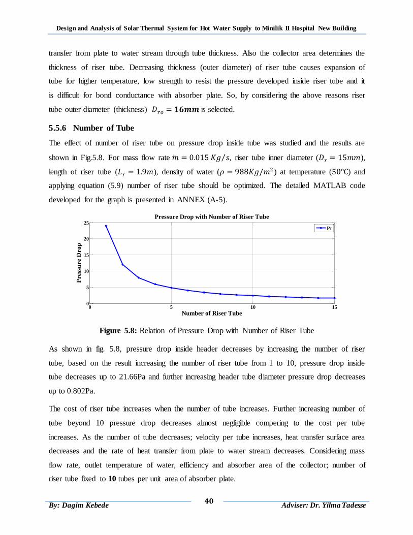
Design and Analysis of Solar Thermal System for Hot Water Supply to Minilik II Hospital New Building
40
By: Dagim Kebede
Adviser: Dr. Yilma Tadesse
transfer from plate to water stream through tube thickness. Also the collector area determines the
thickness of riser tube. Decreasing thickness (outer diameter) of riser tube causes expansion of
tube for higher temperature, low strength to resist the pressure developed inside riser tube and it
is difficult for bond conductance with absorber plate. So, by considering the above reasons riser
tube outer diameter (thickness) is selected.
5.5.6 Number of Tube
The effect of number of riser tube on pressure drop inside tube was studied and the results are
shown in Fig.5.8. For mass flow rate ⁄ , riser tube inner diameter ( ),
length of riser tube ( ), density of water ( ) at temperature ( ) and
applying equation (5.9) number of riser tube should be optimized. The detailed MATLAB code
developed for the graph is presented in ANNEX (A-5).
Figure 5.8: Relation of Pressure Drop with Number of Riser Tube
As shown in fig. 5.8, pressure drop inside header decreases by increasing the number of riser
tube, based on the result increasing the number of riser tube from 1 to 10, pressure drop inside
tube decreases up to 21.66Pa and further increasing header tube diameter pressure drop decreases
up to 0.802Pa.
The cost of riser tube increases when the number of tube increases. Further increasing number of
tube beyond 10 pressure drop decreases almost negligible compering to the cost per tube
increases. As the number of tube decreases; velocity per tube increases, heat transfer surface area
decreases and the rate of heat transfer from plate to water stream decreases. Considering mass
flow rate, outlet temperature of water, efficiency and absorber area of the collector; number of
riser tube fixed to 10 tubes per unit area of absorber plate.
0 5 10 150
5
10
15
20
25
Number of Riser Tube
Press
ure D
ro
p
Pressure Drop with Number of Riser Tube
Pr
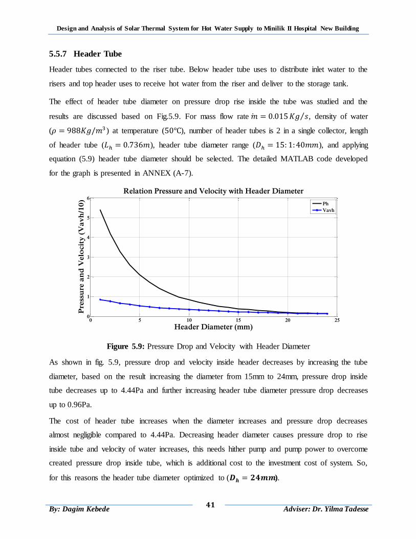
Design and Analysis of Solar Thermal System for Hot Water Supply to Minilik II Hospital New Building
41
By: Dagim Kebede
Adviser: Dr. Yilma Tadesse
5.5.7 Header Tube
Header tubes connected to the riser tube. Below header tube uses to distribute inlet water to the
risers and top header uses to receive hot water from the riser and deliver to the storage tank.
The effect of header tube diameter on pressure drop rise inside the tube was studied and the
results are discussed based on Fig.5.9. For mass flow rate ⁄ , density of water
( ) at temperature ( ), number of header tubes is 2 in a single collector, length
of header tube ( ), header tube diameter range ( ), and applying
equation (5.9) header tube diameter should be selected. The detailed MATLAB code developed
for the graph is presented in ANNEX (A-7).
Figure 5.9: Pressure Drop and Velocity with Header Diameter
As shown in fig. 5.9, pressure drop and velocity inside header decreases by increasing the tube
diameter, based on the result increasing the diameter from 15mm to 24mm, pressure drop inside
tube decreases up to 4.44Pa and further increasing header tube diameter pressure drop decreases
up to 0.96Pa.
The cost of header tube increases when the diameter increases and pressure drop decreases
almost negligible compared to 4.44Pa. Decreasing header diameter causes pressure drop to rise
inside tube and velocity of water increases, this needs hither pump and pump power to overcome
created pressure drop inside tube, which is additional cost to the investment cost of system. So,
for this reasons the header tube diameter optimized to ( ).
0 5 10 15 20 250
1
2
3
4
5
6
Header Diameter (mm)
Pre
ssu
re a
nd
Velo
cit
y (
Va
vh
/10
)
Relation Pressure and Velocity with Header Diameter
Ph
Vavh
Design and Analysis of Solar Thermal System for Hot Water Supply to Minilik II Hospital New Building
42
By: Dagim Kebede
Adviser: Dr. Yilma Tadesse
5.5.8 Insulation Thickness
Heat losses from the back and sides of a collector are reduced by the use of insulation. To
minimize heat losses from the collector, the collector must be 100 percent insulated in
accordance with the requirements of heating circuit system.
Heat is lost to the surroundings from the plate through insulation is:
Edge heat loss and
Bottom heat loss
Insulation heat loss coefficient is the sum of bottom and edge loss coefficient is given as [10]:
( )
The bottom loss coefficient is given by:
( )
The edge loss coefficient is given by:
(
) ( )
Where: and
( ) ( ) And
By assuming heat loss coefficient through insulation ( ), then insulation
thickness is:
((
) )
.(
) /
( )
5.6 Area of a Collector
For collectors, three different area designations are used as the reference variable for output and
yield details.
Design and Analysis of Solar Thermal System for Hot Water Supply to Minilik II Hospital New Building
43
By: Dagim Kebede
Adviser: Dr. Yilma Tadesse
5.6.1 Absorber Area
The absorber area refers exclusively to the absorber. Unit area of absorber plate is assumed for
the design analysis to get ( ) per unit area of mass flow rate of water. For constant
outlet temperature of water and efficiency of a collector, to double the mass flow rate of water to
( ) the absorber area of the collector should be two times the assumed area, which is
equals to 2m2.
5.6.2 Aperture Area
In the case of flat-plate collectors, the aperture area is the visible part of the glass panel, in other
words that area inside the collector frame through which light can enter the appliance.
Aperture area ( ) is given as:
( )
Where: and
Therefore aperture area is equal to:
5.6.3 Gross Collector Area
The gross collector area describes the external dimensions of a collector. As regards the output of
such appliances or their assessment, the gross collector area is irrelevant. However it is important
when planning the installation and when calculating the roof area required.
Gross collector area ( ) is given as:
Where: ( ) ( ) ( )
Therefore gross collector area is equal to:
5.6.4 Collector Edge Area
The edge collector area describes the external edge dimensions of a collector.
Edge collector area is equal to ( ):
( ) ( )
( )
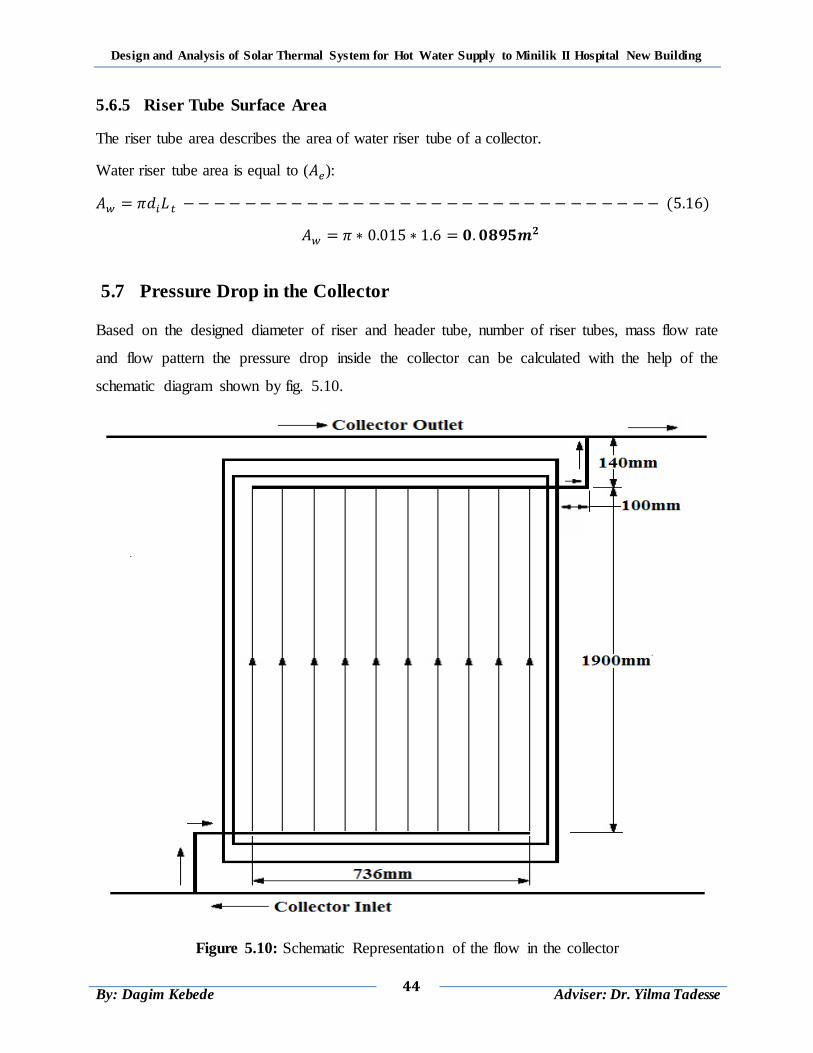
Design and Analysis of Solar Thermal System for Hot Water Supply to Minilik II Hospital New Building
44
By: Dagim Kebede
Adviser: Dr. Yilma Tadesse
5.6.5 Riser Tube Surface Area
The riser tube area describes the area of water riser tube of a collector.
Water riser tube area is equal to ( ):
( )
5.7 Pressure Drop in the Collector
Based on the designed diameter of riser and header tube, number of riser tubes, mass flow rate
and flow pattern the pressure drop inside the collector can be calculated with the help of the
schematic diagram shown by fig. 5.10.
Figure 5.10: Schematic Representation of the flow in the collector
Design and Analysis of Solar Thermal System for Hot Water Supply to Minilik II Hospital New Building
45
By: Dagim Kebede
Adviser: Dr. Yilma Tadesse
At average temperature of ( ) of the property of water is:
Volume flow rate:
( )
Average velocity of fluid in a tube:
( )
Reynolds Number:
( )
(5.19)
If it is laminar flow
( )
If it is turbulent flow
For turbulent flow is read from moody chart.
Pressure drop inside tube is given as:
(
)(
) ( )
5.7.1 Pressure Drop Inside the Risers
Assuming uniform flow rate in each riser the volume flow rate per riser is:
Where: N is the number of risers.
Area of single riser tube:
Design and Analysis of Solar Thermal System for Hot Water Supply to Minilik II Hospital New Building
46
By: Dagim Kebede
Adviser: Dr. Yilma Tadesse
( )
Average velocity in a riser;
Reynolds Number;
Since the it is laminar flow
Where:
(
) .
( )
/
5.7.2 Pressure Drop Inside the Headers
Taking the average volume flow rate:
Ares of single header tube:
( )
Average velocity in the header:
Reynolds Number;
Since the it is laminar flow
For laminar flow pressure drop is:
Where:
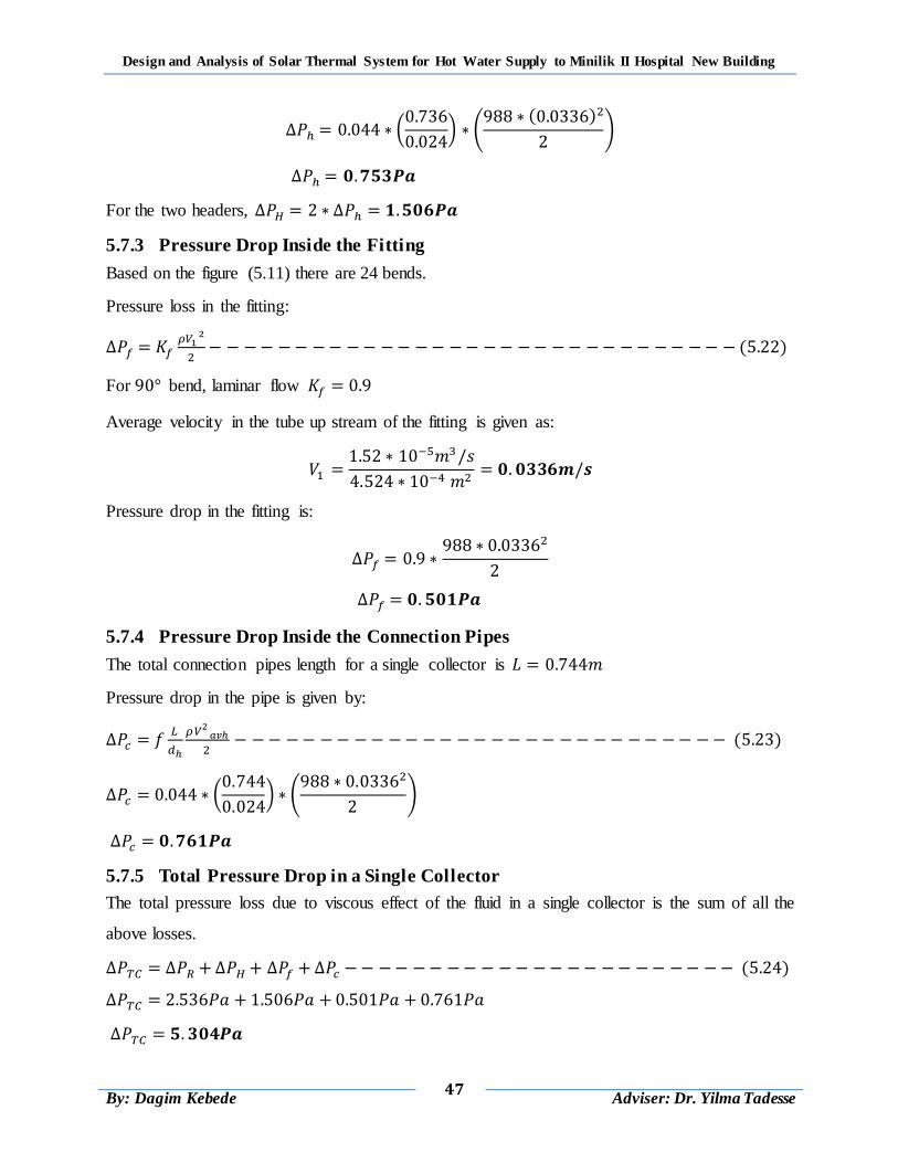
Design and Analysis of Solar Thermal System for Hot Water Supply to Minilik II Hospital New Building
47
By: Dagim Kebede
Adviser: Dr. Yilma Tadesse
(
) .
( )
/
For the two headers,
5.7.3 Pressure Drop Inside the Fitting
Based on the figure (5.11) there are 24 bends.
Pressure loss in the fitting:
( )
For bend, laminar flow
Average velocity in the tube up stream of the fitting is given as:
Pressure drop in the fitting is:
5.7.4 Pressure Drop Inside the Connection Pipes
The total connection pipes length for a single collector is
Pressure drop in the pipe is given by:
( )
(
) .
/
5.7.5 Total Pressure Drop in a Single Collector
The total pressure loss due to viscous effect of the fluid in a single collector is the sum of all the
above losses.
( )
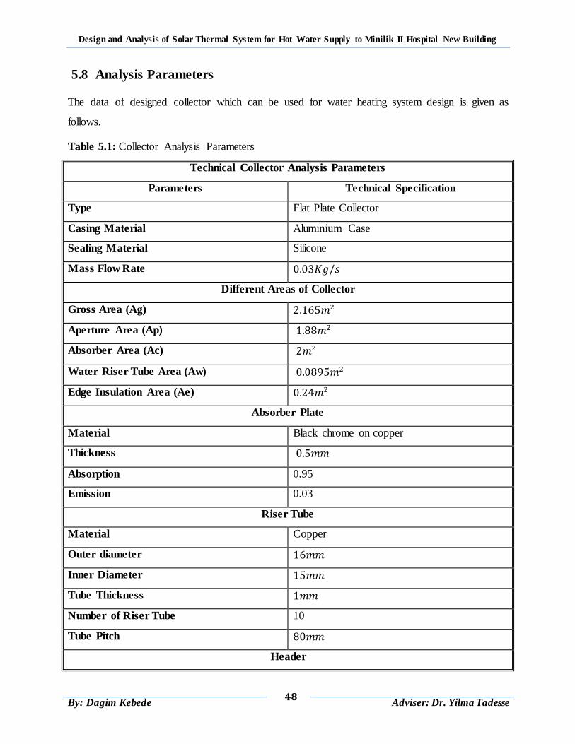
Design and Analysis of Solar Thermal System for Hot Water Supply to Minilik II Hospital New Building
48
By: Dagim Kebede
Adviser: Dr. Yilma Tadesse
5.8 Analysis Parameters
The data of designed collector which can be used for water heating system design is given as
follows.
Table 5.1: Collector Analysis Parameters
Technical Collector Analysis Parameters
Parameters Technical Specification
Type Flat Plate Collector
Casing Material Aluminium Case
Sealing Material Silicone
Mass Flow Rate
Different Areas of Collector
Gross Area (Ag)
Aperture Area (Ap)
Absorber Area (Ac)
Water Riser Tube Area (Aw)
Edge Insulation Area (Ae)
Absorber Plate
Material Black chrome on copper
Thickness
Absorption 0.95
Emission 0.03
Riser Tube
Material Copper
Outer diameter
Inner Diameter
Tube Thickness
Number of Riser Tube 10
Tube Pitch
Header
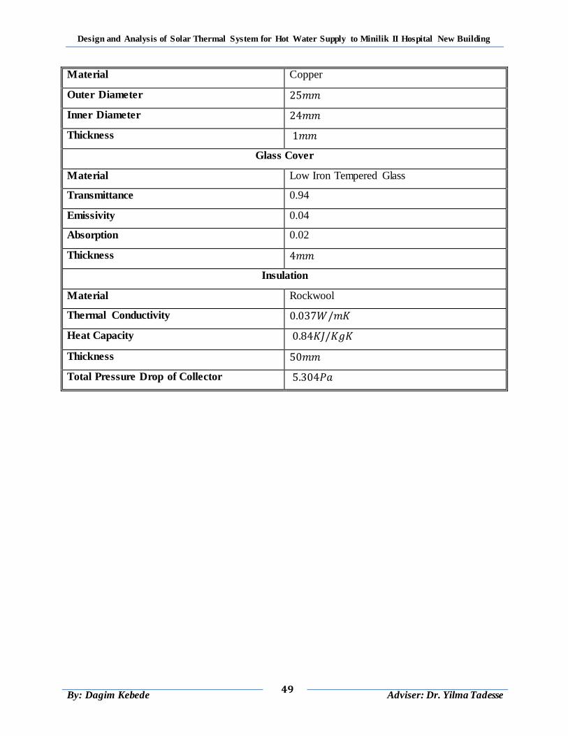
Design and Analysis of Solar Thermal System for Hot Water Supply to Minilik II Hospital New Building
49
By: Dagim Kebede
Adviser: Dr. Yilma Tadesse
Material Copper
Outer Diameter
Inner Diameter
Thickness
Glass Cover
Material Low Iron Tempered Glass
Transmittance 0.94
Emissivity 0.04
Absorption 0.02
Thickness
Insulation
Material Rockwool
Thermal Conductivity
Heat Capacity
Thickness
Total Pressure Drop of Collector
Design and Analysis of Solar Thermal System for Hot Water Supply to Minilik II Hospital New Building
50
By: Dagim Kebede
Adviser: Dr. Yilma Tadesse
CHAPTER 6
THERMAL STORAGE TANK AND INSULATION
6.1 Introduction
Solar energy is a time-dependent energy resource. Thermal storage tank is one of the major
components in large scale solar water heating system to provide a thermal inertia or capacitance
effect. The optimum capacity of an energy storage system depends on the expected time
dependence of solar radiation availability, the nature of loads to be expected on the process, the
degree of reliability needed for the process, the manner in which auxiliary energy is supplied,
and an economic analysis that determines how much of the annual load should be carried by
solar and how much by the auxiliary energy source [5].
Total hot water demand of Minilik II hospital is subjected to different hot water consumption
patterns (two different final load system) in the hospital building. The first final load system is
daily hot water consumption pattern and the second final load system is weekly hot water
consumption pattern. For the design of thermal energy storage tank: total load used is the sum of
the two final loads is considered. In this chapter; design of thermal energy storage tank is
performed for total final load of solar thermal system in the hospital building and selection of
storage tank and insulation material also included.
6.2 Material Selection
The materials must retain their shape and strength during repeated thermal expansion and
contraction; all the while being exposed to the weather. The thermal energy storage tank is
exposed to wind, rain, hail, temperature extremes and ultraviolet radiation. Materials for solar
energy systems must be chosen very carefully. The most important factors are safety,
performance, durability and cost [5].
6.2.1 Material Selection of Thermal Storage Tank
Thermal storage tank may be made from a wide range of materials. Storage tank with selective
galvanization have high efficiency either in maintaining constant operating temperature of the
storage tank by minimizing heat loss from the tank to the surrounding. Properties of selected
thermal storage tank materials are listed in ANNEX C-Table (C-1)
Design and Analysis of Solar Thermal System for Hot Water Supply to Minilik II Hospital New Building
51
By: Dagim Kebede
Adviser: Dr. Yilma Tadesse
Mild steel plate storage tank is selected because of the following reasons:
Due to its low thermal conductivity.
higher performance
higher durability and
Lower cost per unit area and Lower maintenance cost
Higher safety
Lower cost of heat loss per cost of thickness
Also steel jacket (outer cover) galvanization pre painting is used for the selected thermal storage
tank material galvanization.
6.2.2 Material Selection of Thermal Storage Insulation
Heat losses from the thermal storage tank are reduced by the use of insulation. Because of the
risks of water penetration in thermal storage tank consideration should be given to insulation
material selection. At these high temperatures the insulation should not shrink, melt, or give off
vapour (outgas), which could condense on the storage tank outer cover and increase its heat loss
to the surrounding [10]. Properties of various insulation materials are listed in ANNEX C-
Table (C-4).
Glass fiber insulation material is selected for the following reasons:
higher resistance to the water
Lower thermal conductivity properties
Higher durability in the presence of moisture.
Higher temperature resistance
Lower cost per unit area
Higher ultraviolet radiation resistance
6.3 Optimization of Thermal Storage Tank
6.3.1 Volume of Storage Tank
When the daily hot water demand has been determined, the volume of the storage tank can be
specified. It should be some 0.8 to 1.2 fold the daily demand for regions with high solar radiation
and 2 to 2.5 fold the daily demand for regions with lower solar radiation respectively [10].
The volume of the storage tank ( ) is thus calculated as follows:
Design and Analysis of Solar Thermal System for Hot Water Supply to Minilik II Hospital New Building
52
By: Dagim Kebede
Adviser: Dr. Yilma Tadesse
( )
For total daily hot water demand volume of the storage tank ( ) is:
Two storage tank each with the capacity of ( ) is needed.
6.3.2 Diameter and Height of Storage Tank
The shapes of the storage tanks are a right circular cylinder with height to diameter ratio of 2:1.
For daily and weekly hot water consumption pattern of the hospital; thermal storage tank
diameter and height determined as follows:
For circular cylinder with height to diameter ratio of 2:1 height of storage tank is given as:
( )
By substituting equation (6.2) into equation (6.1) the volume of a single storage tank is
rearranged as:
( )
From equation (6.3) the inner diameter of a cylindrical storage tank is given as:
√
( )
A singe thermal storage tank volume is ( );
Therefore, the diameter of storage tank is:
√
Therefore, the height of storage tank is:
6.3.3 Surface Area of Storage Tank
Determining the surface area of thermal storage tank is used to understand the space it occupies
on the roof of hospital building: that helps for proper space consumption of the building roof.
Design and Analysis of Solar Thermal System for Hot Water Supply to Minilik II Hospital New Building
53
By: Dagim Kebede
Adviser: Dr. Yilma Tadesse
The surface area of storage tank is given as:
(
)
( )
The diameter of thermal storage tank is ( );
Therefore, the surface area of storage tank is:
( )
6.4 Optimization of Insulation Thickness
The exterior of a storage tank should be well insulated to retain heat. Heat losses from the
storage tank have great impact on the economic utilization of the system as a whole. For this
reason thickness of insulation should be determined by considering it as one part of the storage
tank design [5, 12].
The determination of the storage tank insulation can be made by using different consideration.
In one case for example, the insulation thickness is taken as an utilizable parameter and
then determined by considering the economic trade-off between the cost of the added
insulation and the benefit gained from the saved solar heat.
The other way of calculating the insulation thickness is as follows: The overall heat
transfer coefficient U across the storage tank is assumed first. Then, the thickness of the
insulation is determined.
For simplification of the problem, the first method is used for the determination of the required
insulation thickness from the economic trade-off between the cost of the added insulation and the
benefit gained from the saved solar heat. Therefore, there should be an optimum thickness of
insulation that corresponds to a minimum combined cost of insulation and heat lost [12].
a) Cost of Insulation Thickness
Glass fiber material is selected for the insulation of thermal storage tank and the cost of glass
fiber gathered from market that is given as 4.5 birr/thickness (mm) per unit area ( ).
The relation between cost of glass fiber (CGF) and thickness is given by:
( ⁄ ) ( ) ( )
Design and Analysis of Solar Thermal System for Hot Water Supply to Minilik II Hospital New Building
54
By: Dagim Kebede
Adviser: Dr. Yilma Tadesse
By substituting the cost of insulation into equation (6.6); relation is rearranged as:
( ) ( )
Notice: that the cost of insulation increases linearly with thickness.
b) Cost of Heat Loss
The cost of heat energy loss from the storage tank is determined based on the cost of energy in
Ethiopia. The cost of energy per ( ) in Ethiopia is equal ( ).
The relation between cost of heat loss (CHL) and thickness of insulation is given by:
( ⁄ ) ( ) ( )
Neglecting the effect of the storage tank material on heat transfer, the temperature difference
across the insulation is taken as ( ).
The rate of heat loss from the tank is then given by:
( )
The overall heat loss coefficient ( ) by the insulation of storage tank is then given by:
( )
Where: , is average wind speed of the location and , is thermal
conductivity of glass fiber.
Therefore, the overall heat loss coefficient ( ) is equal to:
( )
Therefore rate of heat loss from the tank is then equal to:
*(
) + ( )
Area of thermal storage tank and temperature of storage tank and average ambient is:
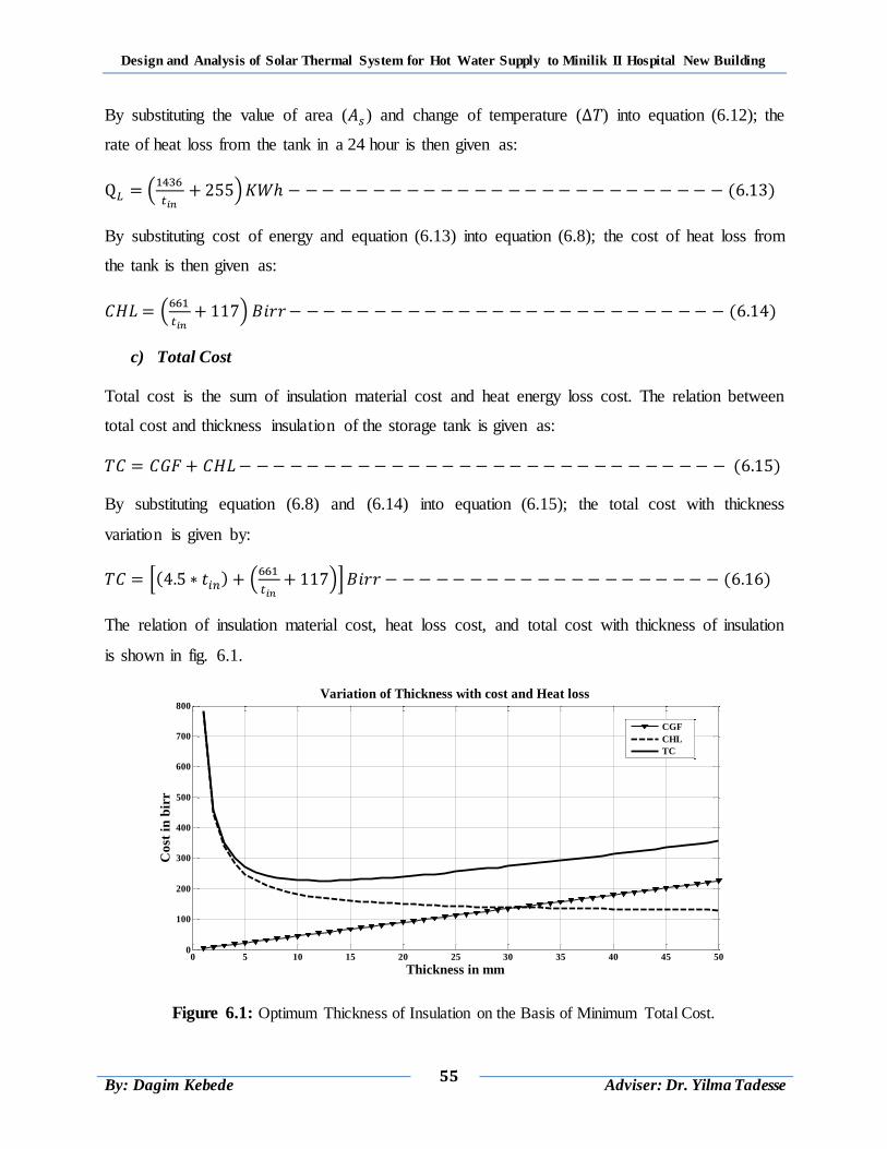
Design and Analysis of Solar Thermal System for Hot Water Supply to Minilik II Hospital New Building
55
By: Dagim Kebede
Adviser: Dr. Yilma Tadesse
By substituting the value of area ( ) and change of temperature ( ) into equation (6.12); the
rate of heat loss from the tank in a 24 hour is then given as:
(
) ( )
By substituting cost of energy and equation (6.13) into equation (6.8); the cost of heat loss from
the tank is then given as:
(
) ( )
c) Total Cost
Total cost is the sum of insulation material cost and heat energy loss cost. The relation between
total cost and thickness insulation of the storage tank is given as:
( )
By substituting equation (6.8) and (6.14) into equation (6.15); the total cost with thickness
variation is given by:
*( ) (
)+ ( )
The relation of insulation material cost, heat loss cost, and total cost with thickness of insulation
is shown in fig. 6.1.
Figure 6.1: Optimum Thickness of Insulation on the Basis of Minimum Total Cost.
0 5 10 15 20 25 30 35 40 45 500
100
200
300
400
500
600
700
800
Thickness in mm
Co
st i
n b
irr
Variation of Thickness with cost and Heat loss
CGF
CHL
TC
Design and Analysis of Solar Thermal System for Hot Water Supply to Minilik II Hospital New Building
56
By: Dagim Kebede
Adviser: Dr. Yilma Tadesse
The total cost, which is the sum of the expressions for the lost heat cost and insulation cost as a
function of thickness; differentiating the total cost equation (6.16) with respect to the thickness;
and setting it equal to zero; is gives as:
( )
Rearranging equation (6.17) and equating to thickness; then the optimum thickness of the
insulation is equal to:
The thickness value satisfying the resulting equation is the optimum thickness. For safety and
long year operation storage tank insulation thickness ( ) is selected.
6.5 Optimization of Storage Tank Thickness and Outer Diameter
6.5.1 Optimum Storage Tank Thickness
It should be realized that thickness of the storage tank does not eliminate heat transfer; it merely
reduces it. The thicker the storage tank, the lower the rate of heat transfer but also the higher the
cost of storage tank material. Therefore, there should be an optimum thickness and outer
diameter of storage tank that corresponds to a minimum combined cost of storage tank material
and heat lost [27].
a) Cost of Storage Tank
Mild steel plate tank is selected for the design of this thermal storage tank and the cost of mild
steel plate gathered from market that is given as 125 birr/thickness (mm) per unit area ( ).
The relation between cost of mild steel plate (CMSP) and thickness is given by:
( ⁄ ) ( ) ( )
By substituting the cost into equation above; relation is rearranged as:
( ) ( )
Notice: that the cost of mild steel plate increases linearly with thickness
b) Cost of Heat Loss
The cost of heat energy loss from the storage tank is determined based on the cost of energy in
Ethiopia. The cost of energy per ( ) in Ethiopia is equal ( ).
Design and Analysis of Solar Thermal System for Hot Water Supply to Minilik II Hospital New Building
57
By: Dagim Kebede
Adviser: Dr. Yilma Tadesse
The relation between cost of heat loss (CHL) and thickness of the storage tank is given as:
( ⁄ ) ( ) ( )
The rate of heat loss from the tank is then given by:
The overall heat loss coefficient ( ) is then given by:
( )
Therefore, the overall heat loss coefficient ( ) is equal to:
(
) ( )
Therefore, the rate of heat loss from the tank is then equal to:
*(
) + ( )
Surface area of thermal storage tank, temperature of storage tank and average ambient is:
By substituting the value of area ( ) and change of temperature ( ) into equation (6.23); the
rate of heat loss from the tank in a 24 hour is then given as:
(
) ( )
Therefore, the cost of heat loss from the tank is then equal to:
(
) ( )
c) Total Cost
Total cost is the sum of insulation material cost and heat energy loss cost. The relation between
total cost and thickness of the storage tank is given as:
( )
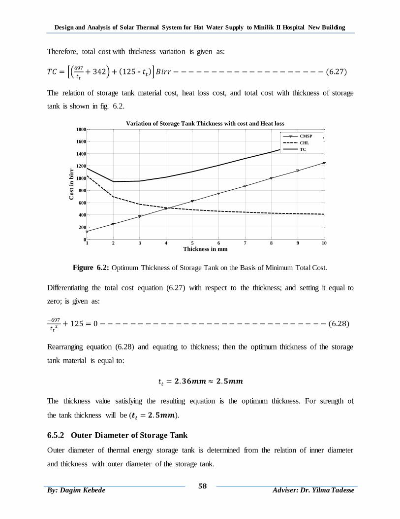
Design and Analysis of Solar Thermal System for Hot Water Supply to Minilik II Hospital New Building
58
By: Dagim Kebede
Adviser: Dr. Yilma Tadesse
Therefore, total cost with thickness variation is given as:
*(
) ( )+ ( )
The relation of storage tank material cost, heat loss cost, and total cost with thickness of storage
tank is shown in fig. 6.2.
Figure 6.2: Optimum Thickness of Storage Tank on the Basis of Minimum Total Cost.
Differentiating the total cost equation (6.27) with respect to the thickness; and setting it equal to
zero; is given as:
( )
Rearranging equation (6.28) and equating to thickness; then the optimum thickness of the storage
tank material is equal to:
The thickness value satisfying the resulting equation is the optimum thickness. For strength of
the tank thickness will be ( ).
6.5.2 Outer Diameter of Storage Tank
Outer diameter of thermal energy storage tank is determined from the relation of inner diameter
and thickness with outer diameter of the storage tank.
1 2 3 4 5 6 7 8 9 100
200
400
600
800
1000
1200
1400
1600
1800
Thickness in mm
Co
st i
n b
irr
Variation of Storage Tank Thickness with cost and Heat loss
CMSP
CHL
TC
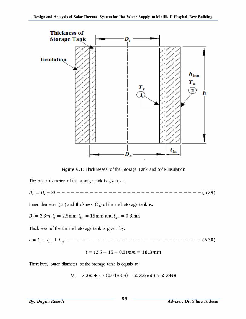
Design and Analysis of Solar Thermal System for Hot Water Supply to Minilik II Hospital New Building
59
By: Dagim Kebede
Adviser: Dr. Yilma Tadesse
Figure 6.3: Thicknesses of the Storage Tank and Side Insulation
The outer diameter of the storage tank is given as:
( )
Inner diameter ( ) and thickness ( ) of thermal storage tank is:
Thickness of the thermal storage tank is given by:
( )
( )
Therefore, outer diameter of the storage tank is equals to:
( )
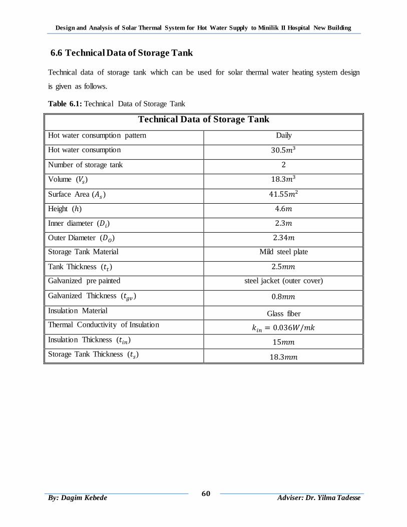
Design and Analysis of Solar Thermal System for Hot Water Supply to Minilik II Hospital New Building
60
By: Dagim Kebede
Adviser: Dr. Yilma Tadesse
6.6 Technical Data of Storage Tank
Technical data of storage tank which can be used for solar thermal water heating system design
is given as follows.
Table 6.1: Technical Data of Storage Tank
Technical Data of Storage Tank
Hot water consumption pattern Daily
Hot water consumption
Number of storage tank
Volume ( )
Surface Area ( )
Height ( )
Inner diameter ( )
Outer Diameter ( )
Storage Tank Material Mild steel plate
Tank Thickness ( )
Galvanized pre painted steel jacket (outer cover)
Galvanized Thickness ( )
Insulation Material Glass fiber
Thermal Conductivity of Insulation
Insulation Thickness ( )
Storage Tank Thickness ( )
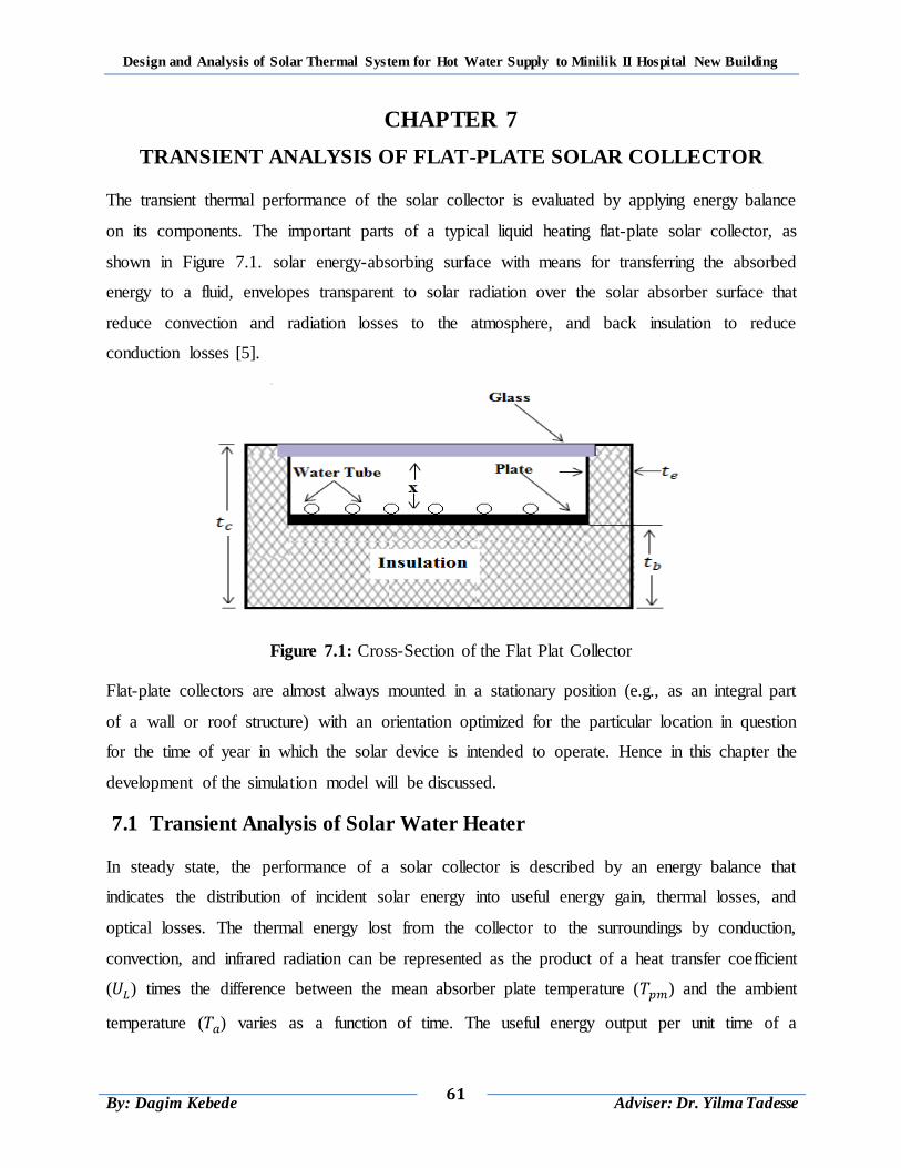
Design and Analysis of Solar Thermal System for Hot Water Supply to Minilik II Hospital New Building
61
By: Dagim Kebede
Adviser: Dr. Yilma Tadesse
CHAPTER 7
TRANSIENT ANALYSIS OF FLAT-PLATE SOLAR COLLECTOR
The transient thermal performance of the solar collector is evaluated by applying energy balance
on its components. The important parts of a typical liquid heating flat-plate solar collector, as
shown in Figure 7.1. solar energy-absorbing surface with means for transferring the absorbed
energy to a fluid, envelopes transparent to solar radiation over the solar absorber surface that
reduce convection and radiation losses to the atmosphere, and back insulation to reduce
conduction losses [5].
Figure 7.1: Cross-Section of the Flat Plat Collector
Flat-plate collectors are almost always mounted in a stationary position (e.g., as an integral part
of a wall or roof structure) with an orientation optimized for the particular location in question
for the time of year in which the solar device is intended to operate. Hence in this chapter the
development of the simulation model will be discussed.
7.1 Transient Analysis of Solar Water Heater
In steady state, the performance of a solar collector is described by an energy balance that
indicates the distribution of incident solar energy into useful energy gain, thermal losses, and
optical losses. The thermal energy lost from the collector to the surroundings by conduction,
convection, and infrared radiation can be represented as the product of a heat transfer coefficient
( ) times the difference between the mean absorber plate temperature ( ) and the ambient
temperature ( ) varies as a function of time. The useful energy output per unit time of a
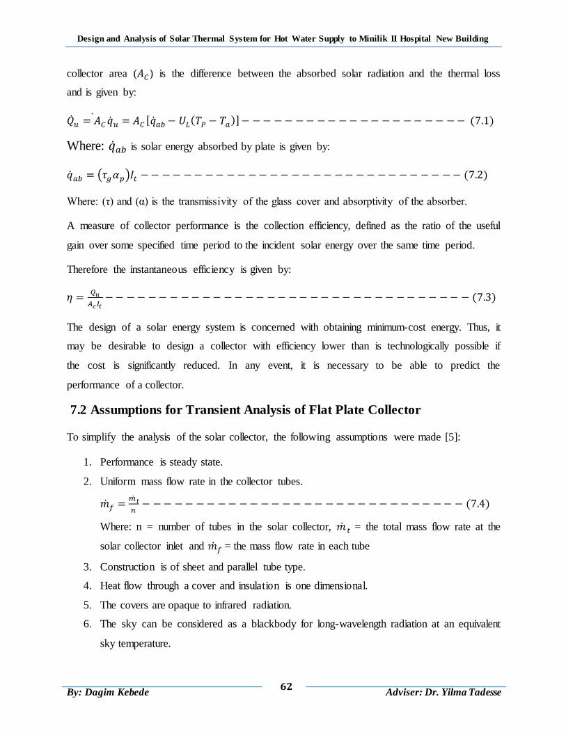
Design and Analysis of Solar Thermal System for Hot Water Supply to Minilik II Hospital New Building
62
By: Dagim Kebede
Adviser: Dr. Yilma Tadesse
collector area ( ) is the difference between the absorbed solar radiation and the thermal loss
and is given by:
( ) ( )
Where: is solar energy absorbed by plate is given by:
( ) ( )
Where: (τ) and (α) is the transmissivity of the glass cover and absorptivity of the absorber.
A measure of collector performance is the collection efficiency, defined as the ratio of the useful
gain over some specified time period to the incident solar energy over the same time period.
Therefore the instantaneous efficiency is given by:
( )
The design of a solar energy system is concerned with obtaining minimum-cost energy. Thus, it
may be desirable to design a collector with efficiency lower than is technologically possible if
the cost is significantly reduced. In any event, it is necessary to be able to predict the
performance of a collector.
7.2 Assumptions for Transient Analysis of Flat Plate Collector
To simplify the analysis of the solar collector, the following assumptions were made [5]:
1. Performance is steady state.
2. Uniform mass flow rate in the collector tubes.
( )
Where: n = number of tubes in the solar collector, = the total mass flow rate at the
solar collector inlet and = the mass flow rate in each tube
3. Construction is of sheet and parallel tube type.
4. Heat flow through a cover and insulation is one dimensional.
5. The covers are opaque to infrared radiation.
6. The sky can be considered as a blackbody for long-wavelength radiation at an equivalent
sky temperature.
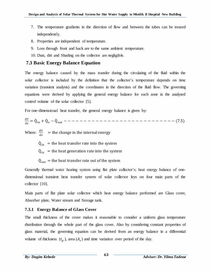
Design and Analysis of Solar Thermal System for Hot Water Supply to Minilik II Hospital New Building
63
By: Dagim Kebede
Adviser: Dr. Yilma Tadesse
7. The temperature gradients in the direction of flow and between the tubes can be treated
independently.
8. Properties are independent of temperature.
9. Loss through front and back are to the same ambient temperature.
10. Dust, dirt and Shading on the collector are negligible.
7.3 Basic Energy Balance Equation
The energy balance caused by the mass transfer during the circulating of the fluid within the
solar collector is included by the definition that the collector‟s temperature depends on time
variation (transient analysis) and the coordinates in the direction of the fluid flow. The governing
equations were derived by applying the general energy balance for each zone in the analyzed
control volume of the solar collector [5].
For one-dimensional heat transfer, the general energy balance is given by:
( )
Where:
Generally thermal water heating system using flat plate collector‟s; heat energy balance of one-
dimensional transient heat transfer system of solar collector leys on four main parts of the
collector [10].
Main parts of flat plate solar collector which heat energy balance performed are Glass cover,
Absorber plate, Water stream and Storage tank.
7.3.1 Energy Balance of Glass Cover
The small thickness of the cover makes it reasonable to consider a uniform glass temperature
distribution through the whole part of the glass cover. Also by considering constant properties of
glass material, the governing equation can be derived from an energy balance in a differential
volume of thickness ( ), area ( ) and time variation over period of the day.
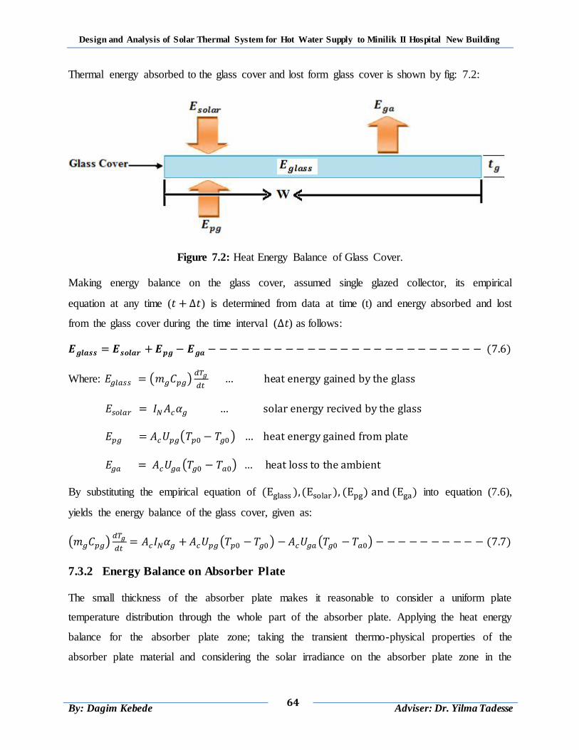
Design and Analysis of Solar Thermal System for Hot Water Supply to Minilik II Hospital New Building
64
By: Dagim Kebede
Adviser: Dr. Yilma Tadesse
Thermal energy absorbed to the glass cover and lost form glass cover is shown by fig: 7.2:
Figure 7.2: Heat Energy Balance of Glass Cover.
Making energy balance on the glass cover, assumed single glazed collector, its empirical
equation at any time ( ) is determined from data at time (t) and energy absorbed and lost
from the glass cover during the time interval ( ) as follows:
( )
Where: ( )
( )
( )
By substituting the empirical equation of ( ) ( ) ( ) ( ) into equation (7.6),
yields the energy balance of the glass cover, given as:
( )
( ) ( ) ( )
7.3.2 Energy Balance on Absorber Plate
The small thickness of the absorber plate makes it reasonable to consider a uniform plate
temperature distribution through the whole part of the absorber plate. Applying the heat energy
balance for the absorber plate zone; taking the transient thermo-physical properties of the
absorber plate material and considering the solar irradiance on the absorber plate zone in the
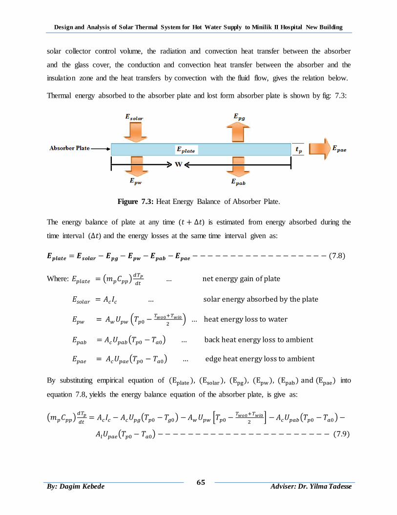
Design and Analysis of Solar Thermal System for Hot Water Supply to Minilik II Hospital New Building
65
By: Dagim Kebede
Adviser: Dr. Yilma Tadesse
solar collector control volume, the radiation and convection heat transfer between the absorber
and the glass cover, the conduction and convection heat transfer between the absorber and the
insulation zone and the heat transfers by convection with the fluid flow, gives the relation below.
Thermal energy absorbed to the absorber plate and lost form absorber plate is shown by fig: 7.3:
Figure 7.3: Heat Energy Balance of Absorber Plate.
The energy balance of plate at any time ( ) is estimated from energy absorbed during the
time interval ( ) and the energy losses at the same time interval given as:
( )
Where: ( )
(
)
( )
( )
By substituting empirical equation of ( ) ( ) ( ) ( ) ( ) ( ) into
equation 7.8, yields the energy balance equation of the absorber plate, is give as:
( )
( ) *
+ ( )
( ) ( )

Design and Analysis of Solar Thermal System for Hot Water Supply to Minilik II Hospital New Building
66
By: Dagim Kebede
Adviser: Dr. Yilma Tadesse
7.3.3 Energy Balance on Water Stream
Figure 7.4 shows the energy balance in a control volume of the working fluid in a flat-plate solar
collector.
Figure 7.4: Energy balance of the working fluid in flat-plate solar collector
Taking in consideration the change in total energy with time and the total heat transferred into
the fluid control volume, the energy balance under transient properties of the working fluid can
be written as:
( )
Where: ( )
( )
By substituting empirical equation of ( ) ( ) ( ) ( ) into equation 7.10,
yields the energy balance of the working fluid, is given as:
( )
(
) ( )
( ) ( )
7.3.4 Energy Balance on Storage Tank
The energy balance of the water in the storage tank is evaluated by taking the hot water extracted
from the solar collector and the heat losses across the storage tank to the ambient into account. In
the model, the level of water in the storage tank is to be controlled by a float valve keeping the
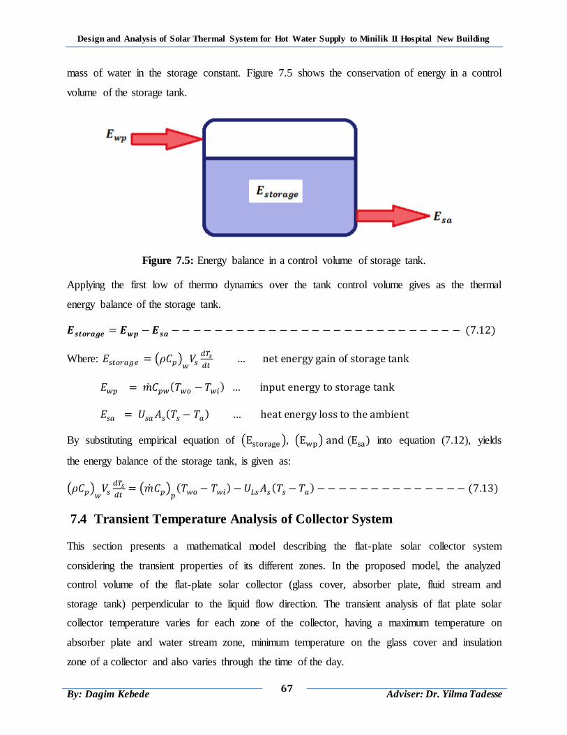
Design and Analysis of Solar Thermal System for Hot Water Supply to Minilik II Hospital New Building
67
By: Dagim Kebede
Adviser: Dr. Yilma Tadesse
mass of water in the storage constant. Figure 7.5 shows the conservation of energy in a control
volume of the storage tank.
Figure 7.5: Energy balance in a control volume of storage tank.
Applying the first low of thermo dynamics over the tank control volume gives as the thermal
energy balance of the storage tank.
( )
Where: ( )
( )
( )
By substituting empirical equation of ( ) ( ) ( ) into equation (7.12), yields
the energy balance of the storage tank, is given as:
( )
( )
( ) ( ) ( )
7.4 Transient Temperature Analysis of Collector System
This section presents a mathematical model describing the flat-plate solar collector system
considering the transient properties of its different zones. In the proposed model, the analyzed
control volume of the flat-plate solar collector (glass cover, absorber plate, fluid stream and
storage tank) perpendicular to the liquid flow direction. The transient analysis of flat plate solar
collector temperature varies for each zone of the collector, having a maximum temperature on
absorber plate and water stream zone, minimum temperature on the glass cover and insulation
zone of a collector and also varies through the time of the day.
Design and Analysis of Solar Thermal System for Hot Water Supply to Minilik II Hospital New Building
68
By: Dagim Kebede
Adviser: Dr. Yilma Tadesse
7.4.1 Glass Cover
The transient analysis of glass cover temperature varies across the width of the glass, having a
maximum on the centerline between the fluid riser tubes and also varies through the time of the
day. The temperature of glass cover derived from the energy balance of the glass zone at any
time ( ), energy absorbed and lost from the glass cover during the given time interval ( ).
Upon integrating energy balance equation (7.7), yields the equation of transient temperature
( ) variation of glass cover, after time interval of ( ) is given as:
( )
( ) { (
( )
( ) ) } (
( ) ) (
( ) ) ( )
7.4.2 The Absorber Plate
The transient temperature of the absorber plate varies across the width of the fin, having a
maximum on the centerline between the fluid riser tubes and varies through the time of the day
that varies solar radiation energy. The absorber plate temperature at any time ( ) can be
determined from conditions at time t and energy absorbed during the time interval and the
energy losses at the same time interval ( ).
Upon integrating energy balance equation (7.9), yields the equation of transient temperature
( ) variation of absorber plate, after time interval of ( ) is given as:
( )
2 .
( )
( )
( )
( )
/ 3 .
( )
/ .
( )
/
(
( ) ) (
( )
( ) ) ( )
7.4.3 The Water Stream
The transient temperature of the water stream varies across the length of the riser tube, having a
maximum at the middle point of the water riser tube and varies through the time of the day that
varies solar radiation energy. Water stream temperature ( ) at any time ( ) can be
determined from data at time t and energy absorbed during the time interval ( ).
Upon integrating energy balance equation (7.11), yields the equation of transient temperature
( ) variation of water stream, after time interval of ( ) is given as:
(( )
( )
) ( (
( )
( )
( )
) ) (( )
( )
( )
) ( )
Design and Analysis of Solar Thermal System for Hot Water Supply to Minilik II Hospital New Building
69
By: Dagim Kebede
Adviser: Dr. Yilma Tadesse
7.4.4 The Storage Tank
The transient temperature of the storage tank varies across the width of the tank, having a
maximum on the middle point of the storage tank and varies through the time of the day that
varies solar radiation energy. Storage tank temperature ( ) at any time ( ) can be
determined from conditions at time (t) and energy absorbed during the time interval ( ) and the
energy losses at the same time interval ( ).
Upon integrating energy balance equation (7.13), yields the equation of transient temperature
( ) variation of storage tank, after time interval of ( ) is given as:
{(( )
( )
)( ) } (
( )
) { (
( )
)} ( )
7.5 The Heat Transfer Correlations
At some typical location on the plate solar energy of amount ( ) is absorbed by the plate is equal
to the incident solar radiation reduced by optical losses. This absorbed energy ( ) is distributed to
thermal losses and to useful energy gain [10]. Thermal losses from the plate through the glass
cover and the insulation and take place by conduction, convection and radiation.
Figure 7.6: Thermal Networks for a One-Cover Flat-Plate Collector
7.5.1 Top Loss Coefficients
The energy loss through the top is the result of convection and radiation between parallel plates.
The steady-state energy transfer between the plate at ( ) and the first cover at ( ) is the same
as between any other two adjacent covers and is also equal to the energy lost to the surroundings
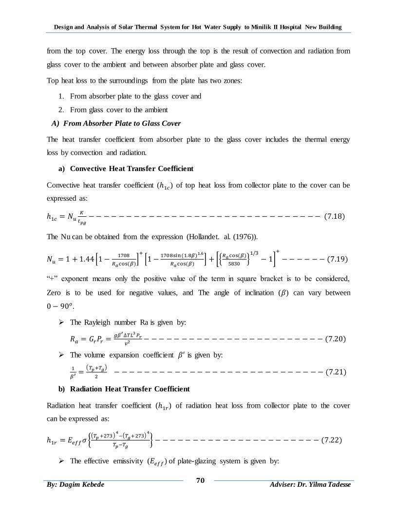
Design and Analysis of Solar Thermal System for Hot Water Supply to Minilik II Hospital New Building
70
By: Dagim Kebede
Adviser: Dr. Yilma Tadesse
from the top cover. The energy loss through the top is the result of convection and radiation from
glass cover to the ambient and between absorber plate and glass cover.
Top heat loss to the surroundings from the plate has two zones:
1. From absorber plate to the glass cover and
2. From glass cover to the ambient
A) From Absorber Plate to Glass Cover
The heat transfer coefficient from absorber plate to the glass cover includes the thermal energy
loss by convection and radiation.
a) Convective Heat Transfer Coefficient
Convective heat transfer coefficient ( ) of top heat loss from collector plate to the cover can be
expressed as:
( )
The Nu can be obtained from the expression (Hollandet. al. (1976)).
*
( )+
* ( )
( )+ [,
( )
-
]
( )
“+” exponent means only the positive value of the term in square bracket is to be considered,
Zero is to be used for negative values, and The angle of inclination ( ) can vary between
.
The Rayleigh number Ra is given by:
( )
The volume expansion coefficient is given by:
( )
( )
b) Radiation Heat Transfer Coefficient
Radiation heat transfer coefficient ( ) of radiation heat loss from collector plate to the cover
can be expressed as:
{( )
( )
} ( )
The effective emissivity ( ) of plate-glazing system is given by:
Design and Analysis of Solar Thermal System for Hot Water Supply to Minilik II Hospital New Building
71
By: Dagim Kebede
Adviser: Dr. Yilma Tadesse
[
]
( )
c) Total heat loss coefficient from Plate to Glass
The total heat transfer coefficient from collector plate to cover is expressed as the sum of
convection ( ) and radiation ( ) heat loss coefficient.
( )
The total heat transfer coefficient from collector plate to cover can be simplified as:
{
( ) ( )
} ( )
B) From Absorber Plate to Water Stream
The heat loss coefficient from absorber plate to the water stream includes the thermal energy loss
by convection and conduction modes of heat transfer. The thickness of absorber plate and riser
tubes is very small that implies transient temperature through the thickness of absorber plate and
riser tube is constant and conduction heat transfer coefficient almost equal to zero, for the
mathematical modeling of temperature only convective method of heat loss coefficient is
applied.
Heat transfer coefficient on the internal surface of the collector tube is given as:
( )
Where the Nusselt number calculated using the empirical Heaton formula suggested by Duffie
and Beckman [2006] is given by:
( ( ⁄ ))
( ( ⁄ )) ( )
( )
With the assumption that the flow inside of tubes is fully developed,
Therefore values of constants in equation (7.27):
( ) respectively, for the
constant heat flux boundary condition.
Design and Analysis of Solar Thermal System for Hot Water Supply to Minilik II Hospital New Building
72
By: Dagim Kebede
Adviser: Dr. Yilma Tadesse
C) From Glass Cover to Ambient
The heat transfer coefficient from glass cover to the ambient includes the thermal energy loss by
convection and radiation.
a) Convective Heat Transfer Coefficient
Convective heat transfer coefficient ( ) of convective heat loss from collector cover to the
ambient can be expressed as:
( )
b) Radiation Heat Transfer Coefficient
Radiation heat transfer coefficient ( ) of radiation heat loss from collector cover to the ambient
can be expressed as:
{( )
( )
} ( )
The sky temperature is given by:
( )
c) Total Heat Loss Coefficient from Glass to Ambient
The total heat transfer coefficient from the cover to ambient is expressed as:
( )
The total heat transfer coefficient from collector cover to ambient can be simplified as:
( ) ( {( )
( )
}) ( )
The effective top heat transfer coefficient from plate to ambient is given by:
( )
The rate of heat loss from the top per unit area can be given as:
( ) ( )
The value of ( ) is calculated by the method of iteration. In general, the cover temperature ( )
is unknown. An arbitrary value of ( ) is assumed and ( ), ( ), ( ) are calculated at the
mean temperature ( ), and Then using these values, the top loss coefficient is calculated.
Design and Analysis of Solar Thermal System for Hot Water Supply to Minilik II Hospital New Building
73
By: Dagim Kebede
Adviser: Dr. Yilma Tadesse
7.5.2 Back Loss Coefficient
The energy loss through the bottom of the collector is represented by two series resistors, R3 and
R4, in Figure 6.4.1, where R3 represents the resistance to heat flow through the insulation by
conduction and R4 represents the convection and radiation resistance to the environment.
Back heat loss from the plate to the surrounding through insulation:
1. Bottom insulation and
2. Edge insulation
a) Bottom Heat Loss Coefficient
Heat is lost from the plate to ambient by conduction through the insulation and subsequently by
convection and radiation from the bottom surface casing. The bottom loss heat coefficient is
given by:
*
+
( )
b) Edge Loss Heat Coefficient
Energy lost from the side of the collector casing may be taken to have exactly the same value as
that from the back, if the thickness of the edge insulation is the same as that of the back
insulation (Tabor, 1958). The edge loss is given as:
(
) ( )
7.5.3 Overall Heat Loss Coefficient
The overall heat loss coefficient is the sum of the top, bottom and edge loss coefficient.
( )
The overall heat lost by the absorber to the ambient per unit area per can be expressed as:
( ) ( )
In the proposed solution method the heat transfer coefficients were calculated using the above
formulas.
Design and Analysis of Solar Thermal System for Hot Water Supply to Minilik II Hospital New Building
74
By: Dagim Kebede
Adviser: Dr. Yilma Tadesse
CHAPTER 8
MATHEMATICAL MODEL PROGRAMING
Transient analysis of absorber plate, glass cover, water stream, and storage tank temperature of
flat plate solar collector is performed by using simulation software‟s. This study uses
mathematical model programing for a flat-plate solar collector with single glass cover working in
parallel channel arrangement model. All designed physical dimensions of the collector can be
entered as inputs, which make it suitable to any single glass cover flat-plate solar collector
without any modifications.
There are different types of software‟s used to code mathematical model for numerical problem
solution; which are MATLAB, C, C++ and FORTRAN. For this study mathematical model
programing software package used to code the model is MATLAB version R2011a. MATLAB is
a programming package that can be used for algorithm development, data analysis, visualization,
and numerical computation. The software is faster than traditional programming languages
including C, C++, and FORTRAN.
The MATLAB code numerically solves the derived model and computes the transient
temperature distributions for any cross-section at the collector beginning at time (t = 0), that is
from the onset of the process till the total time of calculations that entered by user. The detailed
MATLAB code developed for the model is presented in ANNEX (A-10).
8.1 MATLAB Input Parameters
The parameters read from input files at the beginning of the simulation process include:
Latitude of the site, azimuth and slope of the solar collector,
Geometric dimensions and thermophysical properties of the absorber plate, the glazing
and the insulation,
Thermophysical properties of water,
Storage capacity, daily hot water consumption pattern and hot water delivery and cold
water supply temperatures,
Global and diffuse solar radiation and ambient temperature for every hour of the day, and
Design and Analysis of Solar Thermal System for Hot Water Supply to Minilik II Hospital New Building
75
By: Dagim Kebede
Adviser: Dr. Yilma Tadesse
Initial assumption of absorber plate, glass cover, water stream and storage tank
temperature.
8.2 Expected Output of MATLAB
By considering all the boundary conditions in the proposed model taken to be time dependent,
the inputs data used for the numerical code and the mathematical model of numerical equation
described in previous chapters; the expected output from the analysis of MATLAB simulation is
includes:
Hourly temperature of absorber plate, glass cover, water stream and storage tank for the
selected days in each month of the year 2015,
The amount of hot water generated per a unit collector, for the desired output temperature
of hot water per day (the amount of mass flow rate of hot water flow to storage tank per a
collector per day),
The actual performance of designed solar collector; fin efficiency factor ( ), collector
efficiency factor ( ), collector heat removal factor ( ) and collector flow factor ( ),
Total solar heat energy input to the system ( ), the maximum actual useful heat energy
gain ( ) and the maximum heat energy loss in and out of the system ( ) per a unit
collector, and
The maximum actual instantaneous efficiency ( ), average hourly collector efficiency
( ) and average day-long collector efficiency ( ).
8.3 Procedure for Simulation of Solar Thermal Water Heater
The simulation program is used to predict the monthly and annual performance of the solar water
heating system includes the following procedures:
i. Properly writing the programing code of input parameters; basic angles (latitude, azimuth
and slope angles), the solar collector parameters and solar radiation data.
ii. The fraction of the total daily hot water load that occurs in the hour should also be
specified in the simulation process.
iii. Determining sun basic angles (declination, hour, zenith, and incident angle), total and
Incident solar radiation, for each hour of the day.
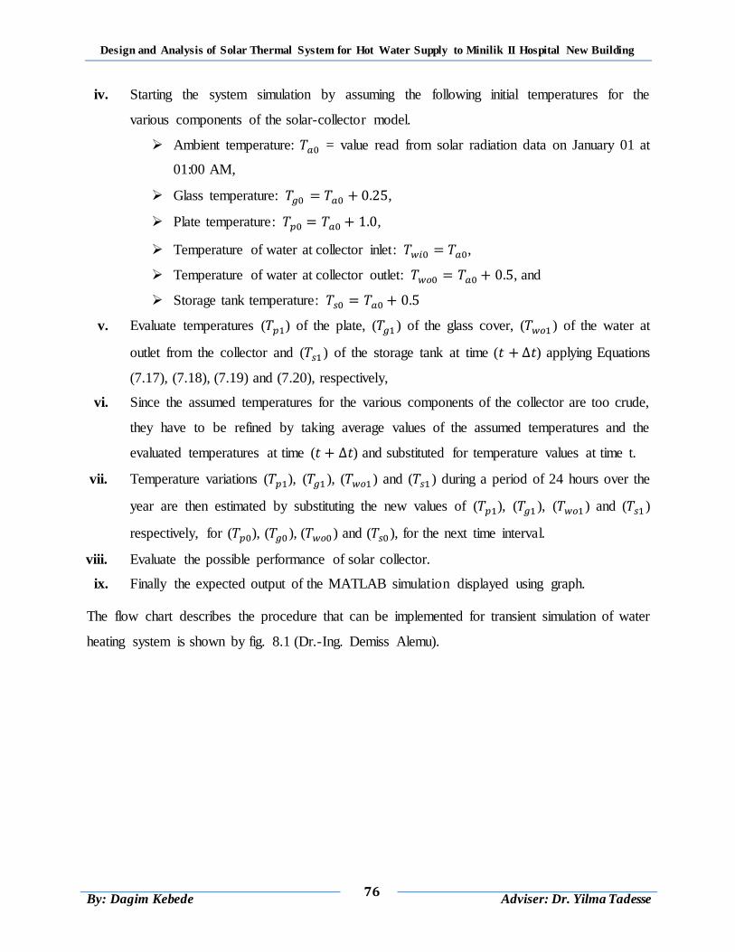
Design and Analysis of Solar Thermal System for Hot Water Supply to Minilik II Hospital New Building
76
By: Dagim Kebede
Adviser: Dr. Yilma Tadesse
iv. Starting the system simulation by assuming the following initial temperatures for the
various components of the solar-collector model.
Ambient temperature: = value read from solar radiation data on January 01 at
01:00 AM,
Glass temperature: ,
Plate temperature: ,
Temperature of water at collector inlet: ,
Temperature of water at collector outlet: , and
Storage tank temperature:
v. Evaluate temperatures ( ) of the plate, ( ) of the glass cover, ( ) of the water at
outlet from the collector and ( ) of the storage tank at time ( ) applying Equations
(7.17), (7.18), (7.19) and (7.20), respectively,
vi. Since the assumed temperatures for the various components of the collector are too crude,
they have to be refined by taking average values of the assumed temperatures and the
evaluated temperatures at time ( ) and substituted for temperature values at time t.
vii. Temperature variations ( ), ( ), ( ) and ( ) during a period of 24 hours over the
year are then estimated by substituting the new values of ( ), ( ), ( ) and ( )
respectively, for ( ), ( ), ( ) and ( ), for the next time interval.
viii. Evaluate the possible performance of solar collector.
ix. Finally the expected output of the MATLAB simulation displayed using graph.
The flow chart describes the procedure that can be implemented for transient simulation of water
heating system is shown by fig. 8.1 (Dr.-Ing. Demiss Alemu).
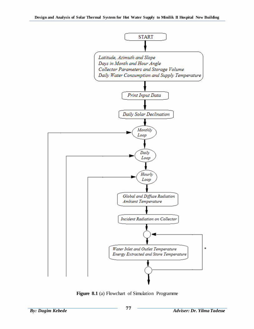
Design and Analysis of Solar Thermal System for Hot Water Supply to Minilik II Hospital New Building
77
By: Dagim Kebede
Adviser: Dr. Yilma Tadesse
Figure 8.1 (a) Flowchart of Simulation Programme
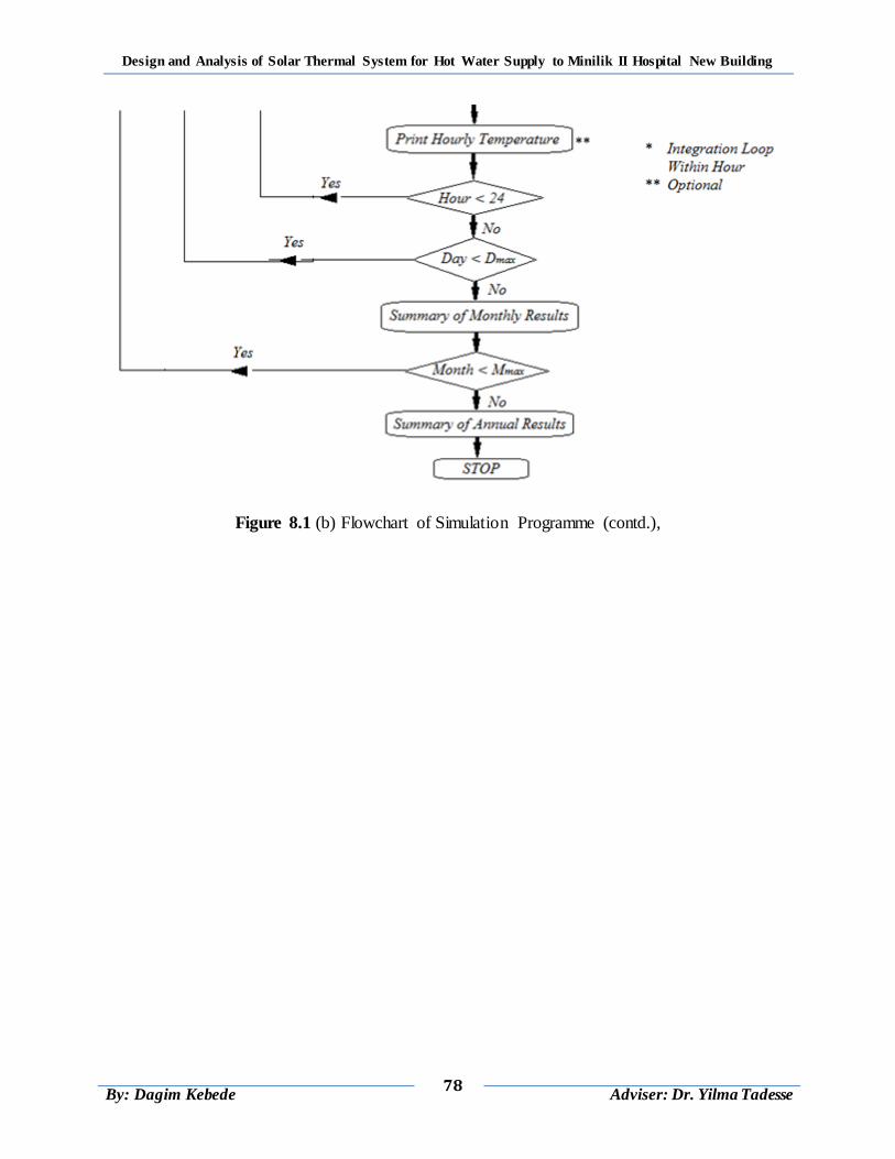
Design and Analysis of Solar Thermal System for Hot Water Supply to Minilik II Hospital New Building
78
By: Dagim Kebede
Adviser: Dr. Yilma Tadesse
Figure 8.1 (b) Flowchart of Simulation Programme (contd.),
Design and Analysis of Solar Thermal System for Hot Water Supply to Minilik II Hospital New Building
79
By: Dagim Kebede
Adviser: Dr. Yilma Tadesse
CHAPTER 9
RESULTS AND DISCUSSION
This chapter presents the results obtained from the theoretical works in previses chapter and
MATLAB simulation. The first part of the analysis was a convergence study for the proposed
numerical code. The second part presents a discussion on numerical obtained temperature
histories, mass flow rate, collector factors, total heat gain, collector system efficiency and annual
solar radiation contribution to heating load. The following sections present the details of each
section.
9.1 Solar Contribution to the Heating Load
Hot water at collector outlet and delivered to thermal energy storage tank at temperature of 60ºc
for the maximum solar contribution to the heating load is achieved during the winter season in
the month February and the minimum is achieved during the summer season in the month of
July.
Figure 9.1: Solar Radiations for Minilik II Hospital
For the analysis of this study solar thermal water heating system 12 month is selected, but for
July and August months auxiliary heating system is needed additional to solar thermal water
0.82
0.83
0.84
0.85
0.86
0.87
0.88
0.89
0.9
Jan Feb Mar Apr May Jun Jul Aug Sep Oct Nov Des
So
lar
Fra
cti
on
Month
Monthly Fraction of Solar Gain (f)
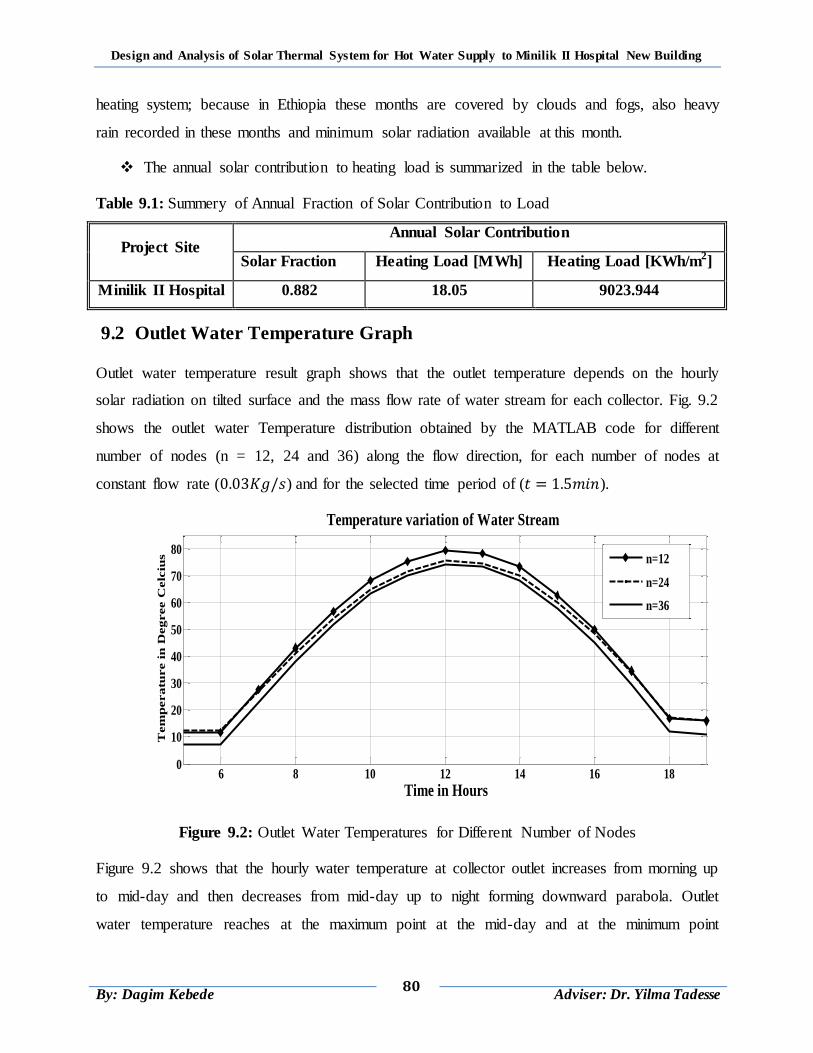
Design and Analysis of Solar Thermal System for Hot Water Supply to Minilik II Hospital New Building
80
By: Dagim Kebede
Adviser: Dr. Yilma Tadesse
heating system; because in Ethiopia these months are covered by clouds and fogs, also heavy
rain recorded in these months and minimum solar radiation available at this month.
The annual solar contribution to heating load is summarized in the table below.
Table 9.1: Summery of Annual Fraction of Solar Contribution to Load
Project Site Annual Solar Contribution
Solar Fraction Heating Load [MWh] Heating Load [KWh/m2]
Minilik II Hospital 0.882 18.05 9023.944
9.2 Outlet Water Temperature Graph
Outlet water temperature result graph shows that the outlet temperature depends on the hourly
solar radiation on tilted surface and the mass flow rate of water stream for each collector. Fig. 9.2
shows the outlet water Temperature distribution obtained by the MATLAB code for different
number of nodes (n = 12, 24 and 36) along the flow direction, for each number of nodes at
constant flow rate ( ) and for the selected time period of ( ).
Figure 9.2: Outlet Water Temperatures for Different Number of Nodes
Figure 9.2 shows that the hourly water temperature at collector outlet increases from morning up
to mid-day and then decreases from mid-day up to night forming downward parabola. Outlet
water temperature reaches at the maximum point at the mid-day and at the minimum point
6 8 10 12 14 16 180
10
20
30
40
50
60
70
80
Time in Hours
Tem
pera
ture i
n D
eg
ree C
elc
ius
Temperature variation of Water Stream
n=12
n=24
n=36
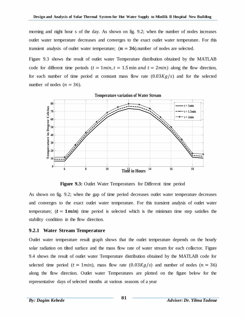
Design and Analysis of Solar Thermal System for Hot Water Supply to Minilik II Hospital New Building
81
By: Dagim Kebede
Adviser: Dr. Yilma Tadesse
morning and night hour s of the day. As shown on fig. 9.2; when the number of nodes increases
outlet water temperature decreases and converges to the exact outlet water temperature. For this
transient analysis of outlet water temperature; ( ).number of nodes are selected.
Figure 9.3 shows the result of outlet water Temperature distribution obtained by the MATLAB
code for different time periods ( ) along the flow direction,
for each number of time period at constant mass flow rate ( ) and for the selected
number of nodes ( ).
Figure 9.3: Outlet Water Temperatures for Different time period
As shown on fig. 9.2; when the gap of time period decreases outlet water temperature decreases
and converges to the exact outlet water temperature. For this transient analysis of outlet water
temperature; ( ) time period is selected which is the minimum time step satisfies the
stability condition in the flow direction.
9.2.1 Water Stream Temperature
Outlet water temperature result graph shows that the outlet temperature depends on the hourly
solar radiation on tilted surface and the mass flow rate of water stream for each collector. Figure
9.4 shows the result of outlet water Temperature distribution obtained by the MATLAB code for
selected time period ( ), mass flow rate ( ) and number of nodes ( )
along the flow direction. Outlet water Temperatures are plotted on the figure below for the
representative days of selected months at various seasons of a year
6 8 10 12 14 16 180
10
20
30
40
50
60
70
80
Time in Hours
Tem
peratu
re i
n D
egree C
elc
ius
Temperature variation of Water Stream
t = 1min
t = 1.5min
t = 2min
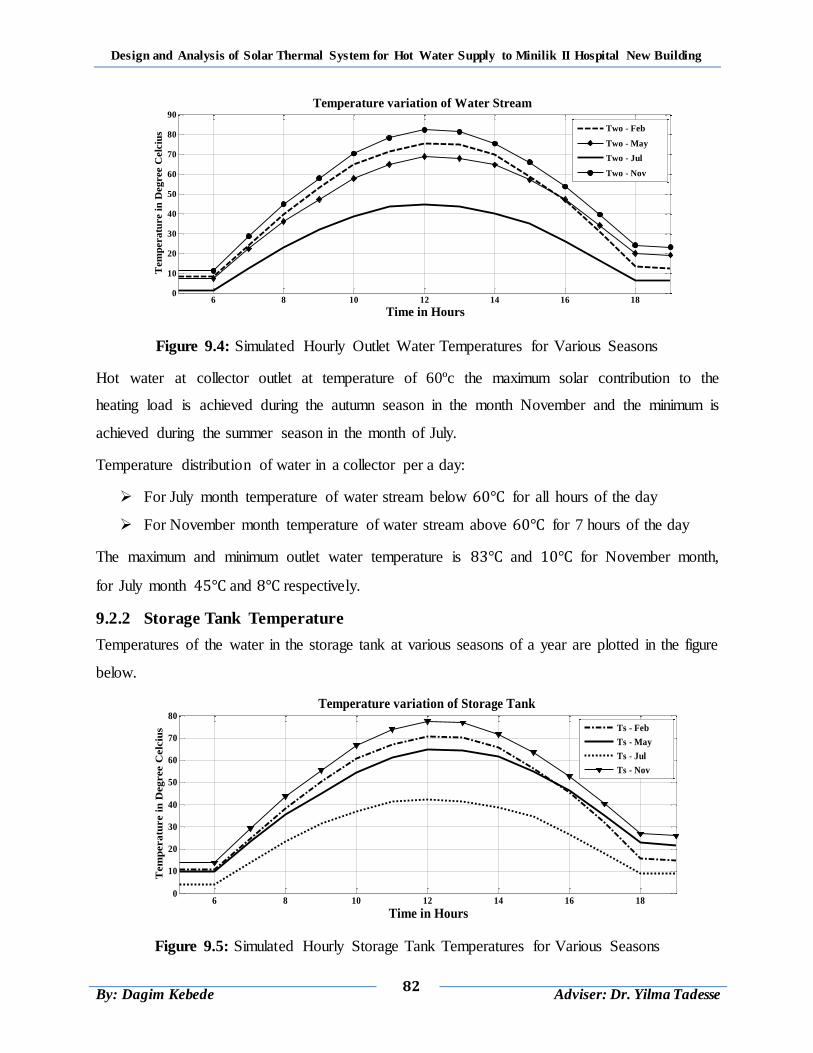
Design and Analysis of Solar Thermal System for Hot Water Supply to Minilik II Hospital New Building
82
By: Dagim Kebede
Adviser: Dr. Yilma Tadesse
Figure 9.4: Simulated Hourly Outlet Water Temperatures for Various Seasons
Hot water at collector outlet at temperature of 60ºc the maximum solar contribution to the
heating load is achieved during the autumn season in the month November and the minimum is
achieved during the summer season in the month of July.
Temperature distribution of water in a collector per a day:
For July month temperature of water stream below for all hours of the day
For November month temperature of water stream above for 7 hours of the day
The maximum and minimum outlet water temperature is and for November month,
for July month and respectively.
9.2.2 Storage Tank Temperature
Temperatures of the water in the storage tank at various seasons of a year are plotted in the figure
below.
Figure 9.5: Simulated Hourly Storage Tank Temperatures for Various Seasons
6 8 10 12 14 16 180
10
20
30
40
50
60
70
80
90
Time in Hours
Tem
pera
ture i
n D
eg
ree C
elc
ius
Temperature variation of Water Stream
Two - Feb
Two - May
Two - Jul
Two - Nov
6 8 10 12 14 16 180
10
20
30
40
50
60
70
80
Time in Hours
Tem
pera
ture i
n D
eg
ree C
elc
ius
Temperature variation of Storage Tank
Ts - Feb
Ts - May
Ts - Jul
Ts - Nov
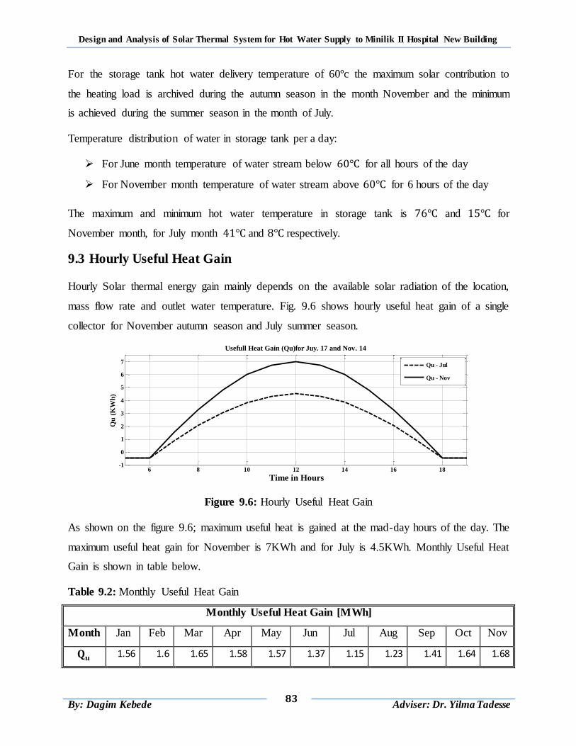
Design and Analysis of Solar Thermal System for Hot Water Supply to Minilik II Hospital New Building
83
By: Dagim Kebede
Adviser: Dr. Yilma Tadesse
For the storage tank hot water delivery temperature of 60ºc the maximum solar contribution to
the heating load is archived during the autumn season in the month November and the minimum
is achieved during the summer season in the month of July.
Temperature distribution of water in storage tank per a day:
For June month temperature of water stream below for all hours of the day
For November month temperature of water stream above for 6 hours of the day
The maximum and minimum hot water temperature in storage tank is and for
November month, for July month and respectively.
9.3 Hourly Useful Heat Gain
Hourly Solar thermal energy gain mainly depends on the available solar radiation of the location,
mass flow rate and outlet water temperature. Fig. 9.6 shows hourly useful heat gain of a single
collector for November autumn season and July summer season.
Figure 9.6: Hourly Useful Heat Gain
As shown on the figure 9.6; maximum useful heat is gained at the mad-day hours of the day. The
maximum useful heat gain for November is 7KWh and for July is 4.5KWh. Monthly Useful Heat
Gain is shown in table below.
Table 9.2: Monthly Useful Heat Gain
Monthly Useful Heat Gain [MWh]
Month Jan Feb Mar Apr May Jun Jul Aug Sep Oct Nov
1.56 1.6 1.65 1.58 1.57 1.37 1.15 1.23 1.41 1.64 1.68
6 8 10 12 14 16 18-1
0
1
2
3
4
5
6
7
Time in Hours
Qu
(K
Wh
)
Usefull Heat Gain (Qu)for Juy. 17 and Nov. 14
Qu - Jul
Qu - Nov
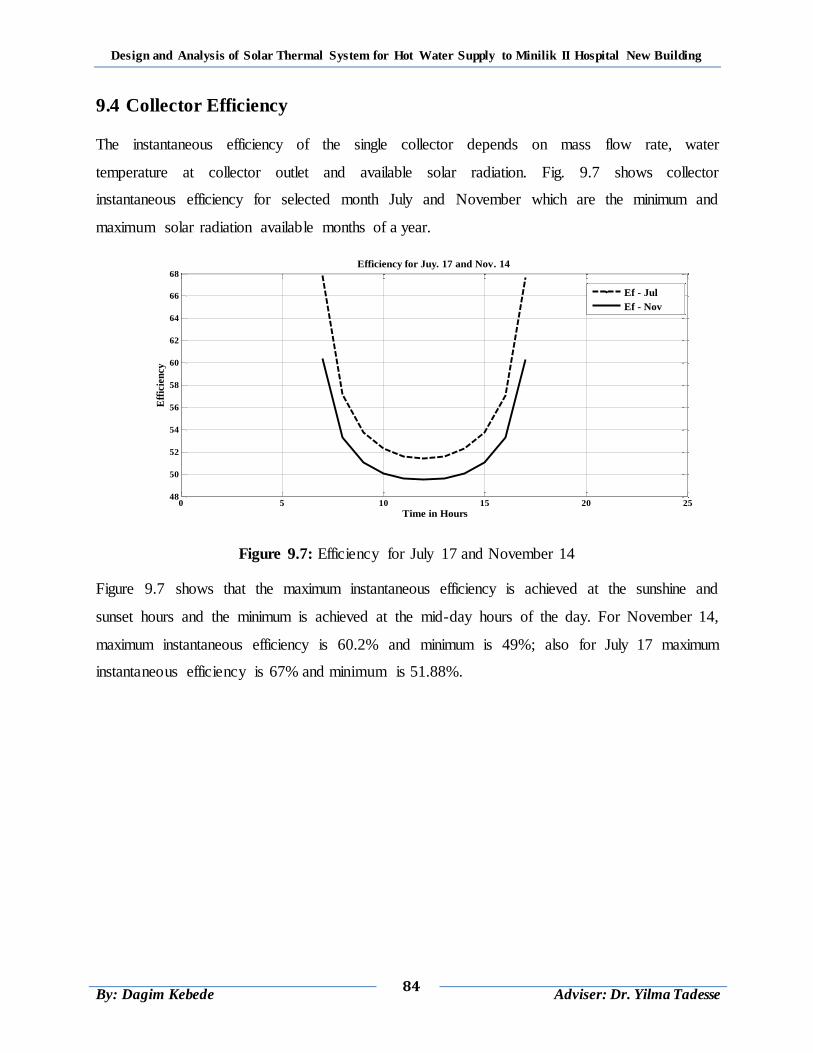
Design and Analysis of Solar Thermal System for Hot Water Supply to Minilik II Hospital New Building
84
By: Dagim Kebede
Adviser: Dr. Yilma Tadesse
9.4 Collector Efficiency
The instantaneous efficiency of the single collector depends on mass flow rate, water
temperature at collector outlet and available solar radiation. Fig. 9.7 shows collector
instantaneous efficiency for selected month July and November which are the minimum and
maximum solar radiation available months of a year.
Figure 9.7: Efficiency for July 17 and November 14
Figure 9.7 shows that the maximum instantaneous efficiency is achieved at the sunshine and
sunset hours and the minimum is achieved at the mid-day hours of the day. For November 14,
maximum instantaneous efficiency is 60.2% and minimum is 49%; also for July 17 maximum
instantaneous efficiency is 67% and minimum is 51.88%.
0 5 10 15 20 2548
50
52
54
56
58
60
62
64
66
68
Time in Hours
Eff
icie
ncy
Efficiency for Juy. 17 and Nov. 14
Ef - Jul
Ef - Nov
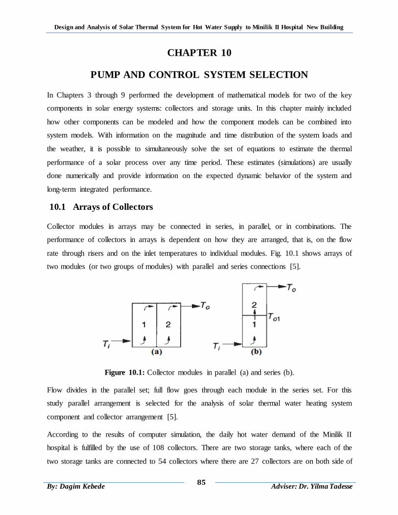
Design and Analysis of Solar Thermal System for Hot Water Supply to Minilik II Hospital New Building
85
By: Dagim Kebede
Adviser: Dr. Yilma Tadesse
CHAPTER 10
PUMP AND CONTROL SYSTEM SELECTION
In Chapters 3 through 9 performed the development of mathematical models for two of the key
components in solar energy systems: collectors and storage units. In this chapter mainly included
how other components can be modeled and how the component models can be combined into
system models. With information on the magnitude and time distribution of the system loads and
the weather, it is possible to simultaneously solve the set of equations to estimate the thermal
performance of a solar process over any time period. These estimates (simulations) are usually
done numerically and provide information on the expected dynamic behavior of the system and
long-term integrated performance.
10.1 Arrays of Collectors
Collector modules in arrays may be connected in series, in parallel, or in combinations. The
performance of collectors in arrays is dependent on how they are arranged, that is, on the flow
rate through risers and on the inlet temperatures to individual modules. Fig. 10.1 shows arrays of
two modules (or two groups of modules) with parallel and series connections [5].
Figure 10.1: Collector modules in parallel (a) and series (b).
Flow divides in the parallel set; full flow goes through each module in the series set. For this
study parallel arrangement is selected for the analysis of solar thermal water heating system
component and collector arrangement [5].
According to the results of computer simulation, the daily hot water demand of the Minilik II
hospital is fulfilled by the use of 108 collectors. There are two storage tanks, where each of the
two storage tanks are connected to 54 collectors where there are 27 collectors are on both side of
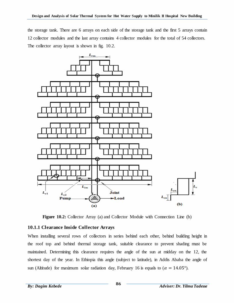
Design and Analysis of Solar Thermal System for Hot Water Supply to Minilik II Hospital New Building
86
By: Dagim Kebede
Adviser: Dr. Yilma Tadesse
the storage tank. There are 6 arrays on each side of the storage tank and the first 5 arrays contain
12 collector modules and the last array contains 4 collector modules for the total of 54 collectors.
The collector array layout is shown in fig. 10.2.
Figure 10.2: Collector Array (a) and Collector Module with Connection Line (b)
10.1.1 Clearance Inside Collector Arrays
When installing several rows of collectors in series behind each other, behind building height in
the roof top and behind thermal storage tank, suitable clearance to prevent shading must be
maintained. Determining this clearance requires the angle of the sun at midday on the 12, the
shortest day of the year. In Ethiopia this angle (subject to latitude), in Addis Ababa the angle of
sun (Altitude) for maximum solar radiation day, February 16 is equals to ( ).
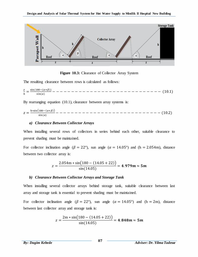
Design and Analysis of Solar Thermal System for Hot Water Supply to Minilik II Hospital New Building
87
By: Dagim Kebede
Adviser: Dr. Yilma Tadesse
Figure 10.3: Clearance of Collector Array System
The resulting clearance between rows is calculated as follows:
( ( ))
( ) ( )
By rearranging equation (10.1), clearance between array systems is:
( ( ))
( ) ( )
a) Clearance Between Collector Arrays
When installing several rows of collectors in series behind each other, suitable clearance to
prevent shading must be maintained.
For collector inclination angle ( ), sun angle ( ) and ( ), distance
between two collector array is:
( ( ))
( )
b) Clearance Between Collector Arrays and Storage Tank
When installing several collector arrays behind storage tank, suitable clearance between last
array and storage tank is essential to prevent shading must be maintained.
For collector inclination angle ( ), sun angle ( ) and ( ), distance
between last collector array and storage tank is:
( ( ))
( )
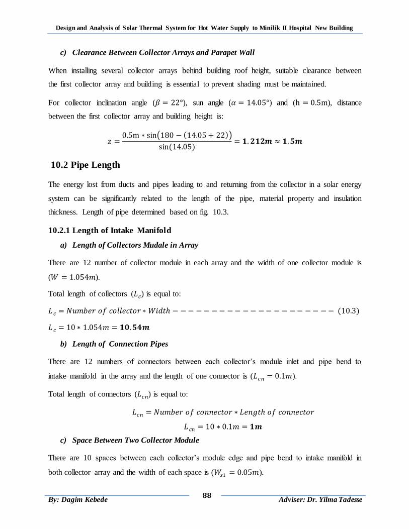
Design and Analysis of Solar Thermal System for Hot Water Supply to Minilik II Hospital New Building
88
By: Dagim Kebede
Adviser: Dr. Yilma Tadesse
c) Clearance Between Collector Arrays and Parapet Wall
When installing several collector arrays behind building roof height, suitable clearance between
the first collector array and building is essential to prevent shading must be maintained.
For collector inclination angle ( ), sun angle ( ) and ( ), distance
between the first collector array and building height is:
( ( ))
( )
10.2 Pipe Length
The energy lost from ducts and pipes leading to and returning from the collector in a solar energy
system can be significantly related to the length of the pipe, material property and insulation
thickness. Length of pipe determined based on fig. 10.3.
10.2.1 Length of Intake Manifold
a) Length of Collectors Mudale in Array
There are 12 number of collector module in each array and the width of one collector module is
( ).
Total length of collectors ( ) is equal to:
( )
b) Length of Connection Pipes
There are 12 numbers of connectors between each collector‟s module inlet and pipe bend to
intake manifold in the array and the length of one connector is ( ).
Total length of connectors ( ) is equal to:
c) Space Between Two Collector Module
There are 10 spaces between each collector‟s module edge and pipe bend to intake manifold in
both collector array and the width of each space is ( ).
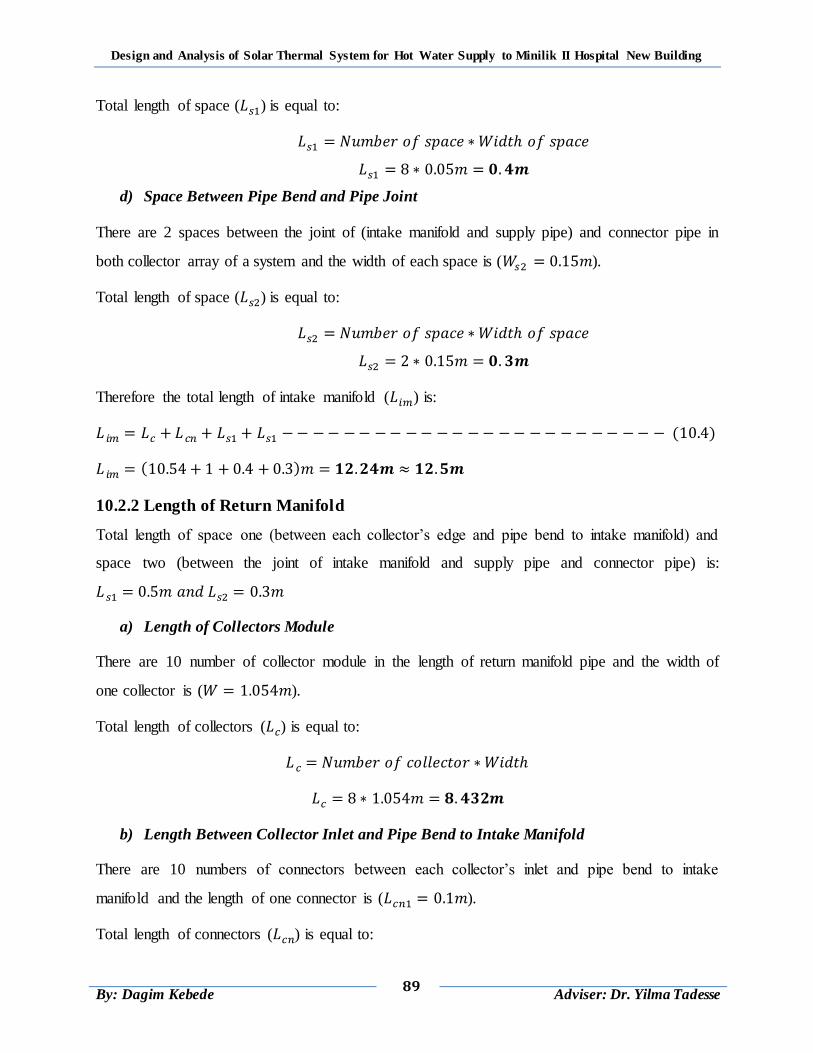
Design and Analysis of Solar Thermal System for Hot Water Supply to Minilik II Hospital New Building
89
By: Dagim Kebede
Adviser: Dr. Yilma Tadesse
Total length of space ( ) is equal to:
d) Space Between Pipe Bend and Pipe Joint
There are 2 spaces between the joint of (intake manifold and supply pipe) and connector pipe in
both collector array of a system and the width of each space is ( ).
Total length of space ( ) is equal to:
Therefore the total length of intake manifold ( ) is:
( )
( )
10.2.2 Length of Return Manifold
Total length of space one (between each collector‟s edge and pipe bend to intake manifold) and
space two (between the joint of intake manifold and supply pipe and connector pipe) is:
a) Length of Collectors Module
There are 10 number of collector module in the length of return manifold pipe and the width of
one collector is ( ).
Total length of collectors ( ) is equal to:
b) Length Between Collector Inlet and Pipe Bend to Intake Manifold
There are 10 numbers of connectors between each collector‟s inlet and pipe bend to intake
manifold and the length of one connector is ( ).
Total length of connectors ( ) is equal to:
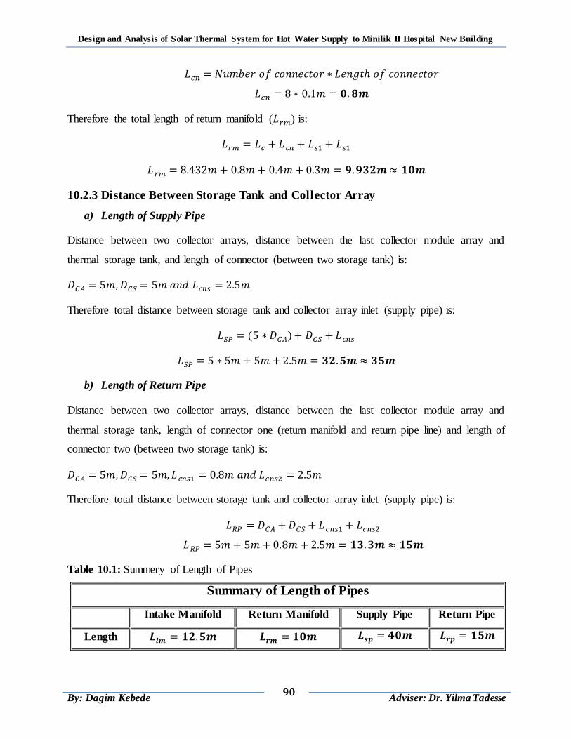
Design and Analysis of Solar Thermal System for Hot Water Supply to Minilik II Hospital New Building
90
By: Dagim Kebede
Adviser: Dr. Yilma Tadesse
Therefore the total length of return manifold ( ) is:
10.2.3 Distance Between Storage Tank and Collector Array
a) Length of Supply Pipe
Distance between two collector arrays, distance between the last collector module array and
thermal storage tank, and length of connector (between two storage tank) is:
Therefore total distance between storage tank and collector array inlet (supply pipe) is:
( )
b) Length of Return Pipe
Distance between two collector arrays, distance between the last collector module array and
thermal storage tank, length of connector one (return manifold and return pipe line) and length of
connector two (between two storage tank) is:
Therefore total distance between storage tank and collector array inlet (supply pipe) is:
Table 10.1: Summery of Length of Pipes
Summary of Length of Pipes
Intake Manifold Return Manifold Supply Pipe Return Pipe
Length
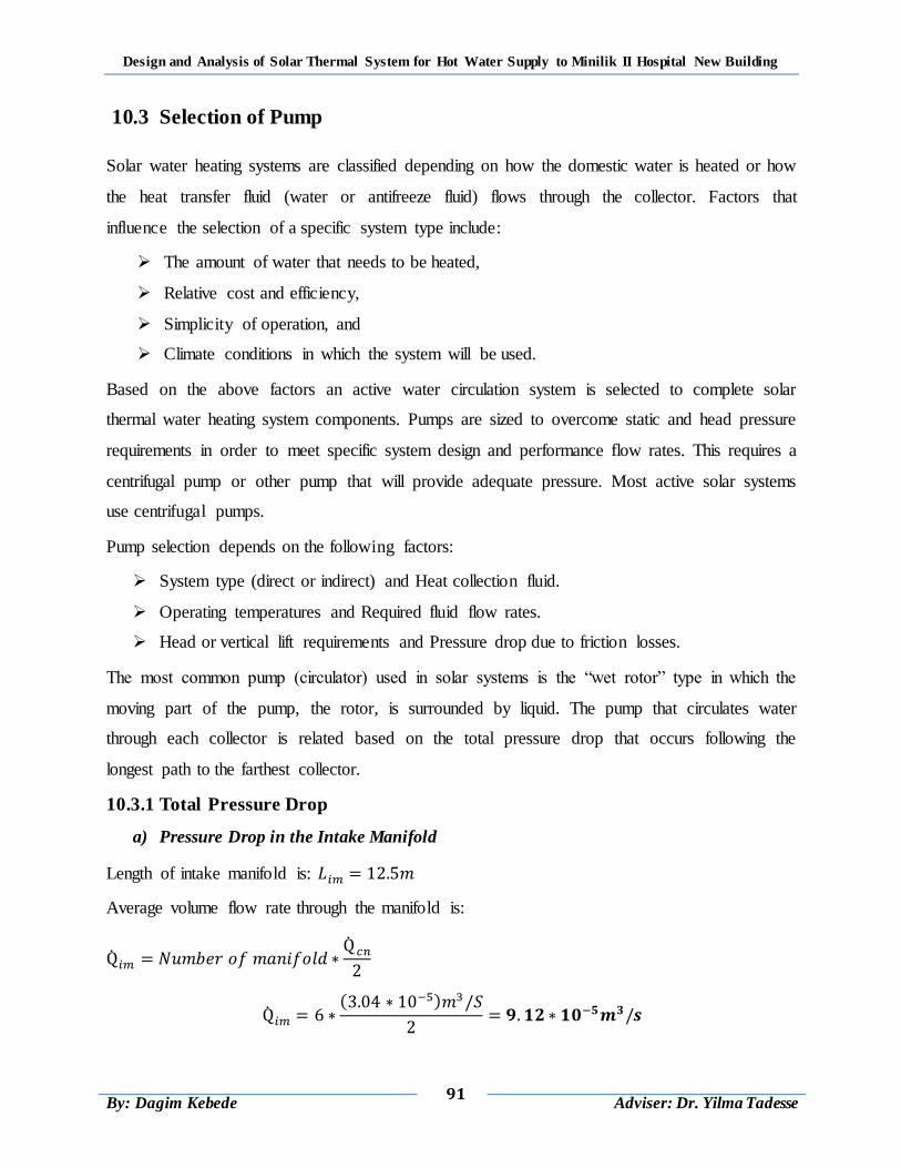
Design and Analysis of Solar Thermal System for Hot Water Supply to Minilik II Hospital New Building
91
By: Dagim Kebede
Adviser: Dr. Yilma Tadesse
10.3 Selection of Pump
Solar water heating systems are classified depending on how the domestic water is heated or how
the heat transfer fluid (water or antifreeze fluid) flows through the collector. Factors that
influence the selection of a specific system type include:
The amount of water that needs to be heated,
Relative cost and efficiency,
Simplicity of operation, and
Climate conditions in which the system will be used.
Based on the above factors an active water circulation system is selected to complete solar
thermal water heating system components. Pumps are sized to overcome static and head pressure
requirements in order to meet specific system design and performance flow rates. This requires a
centrifugal pump or other pump that will provide adequate pressure. Most active solar systems
use centrifugal pumps.
Pump selection depends on the following factors:
System type (direct or indirect) and Heat collection fluid.
Operating temperatures and Required fluid flow rates.
Head or vertical lift requirements and Pressure drop due to friction losses.
The most common pump (circulator) used in solar systems is the “wet rotor” type in which the
moving part of the pump, the rotor, is surrounded by liquid. The pump that circulates water
through each collector is related based on the total pressure drop that occurs following the
longest path to the farthest collector.
10.3.1 Total Pressure Drop
a) Pressure Drop in the Intake Manifold
Length of intake manifold is:
Average volume flow rate through the manifold is:
( )
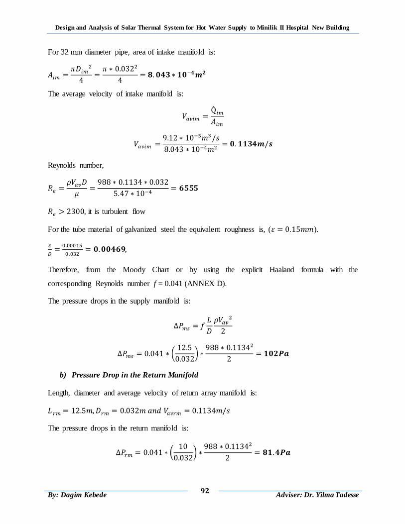
Design and Analysis of Solar Thermal System for Hot Water Supply to Minilik II Hospital New Building
92
By: Dagim Kebede
Adviser: Dr. Yilma Tadesse
For 32 mm diameter pipe, area of intake manifold is:
The average velocity of intake manifold is:
Reynolds number,
, it is turbulent flow
For the tube material of galvanized steel the equivalent roughness is, ( ).
,
Therefore, from the Moody Chart or by using the explicit Haaland formula with the
corresponding Reynolds number f = 0.041 (ANNEX D).
The pressure drops in the supply manifold is:
(
)
b) Pressure Drop in the Return Manifold
Length, diameter and average velocity of return array manifold is:
The pressure drops in the return manifold is:
(
)
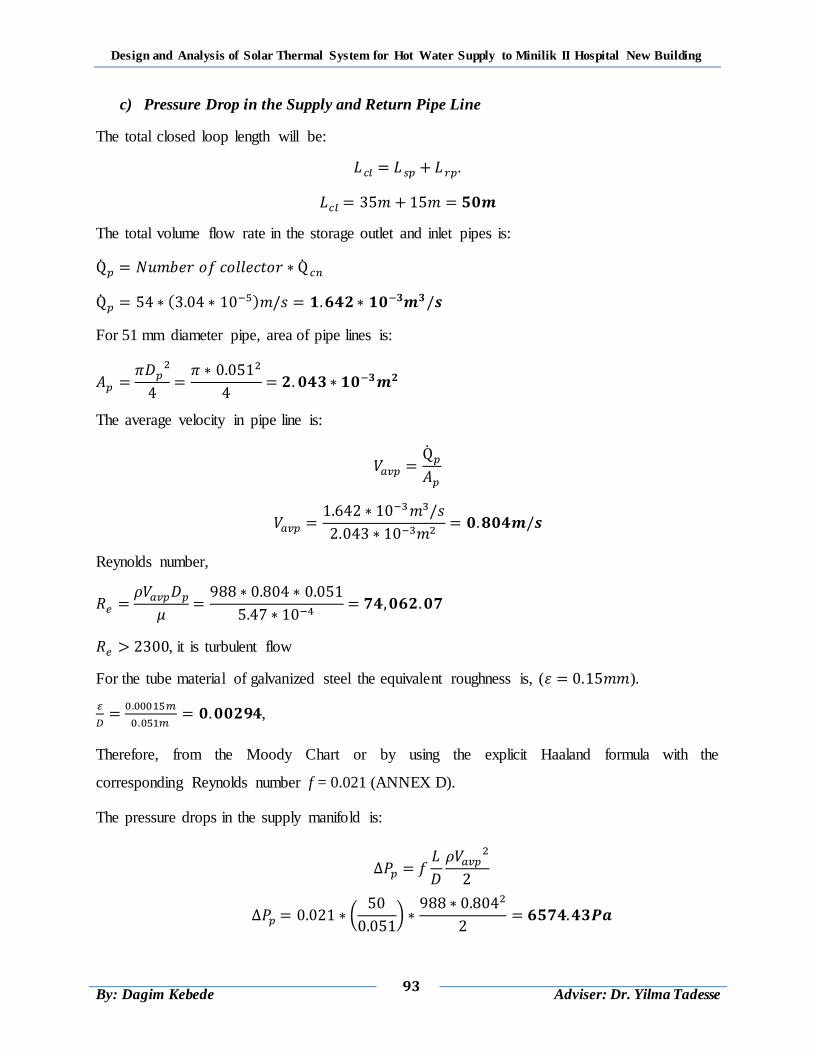
Design and Analysis of Solar Thermal System for Hot Water Supply to Minilik II Hospital New Building
93
By: Dagim Kebede
Adviser: Dr. Yilma Tadesse
c) Pressure Drop in the Supply and Return Pipe Line
The total closed loop length will be:
.
The total volume flow rate in the storage outlet and inlet pipes is:
( )
For 51 mm diameter pipe, area of pipe lines is:
The average velocity in pipe line is:
Reynolds number,
, it is turbulent flow
For the tube material of galvanized steel the equivalent roughness is, ( ).
,
Therefore, from the Moody Chart or by using the explicit Haaland formula with the
corresponding Reynolds number f = 0.021 (ANNEX D).
The pressure drops in the supply manifold is:
(
)
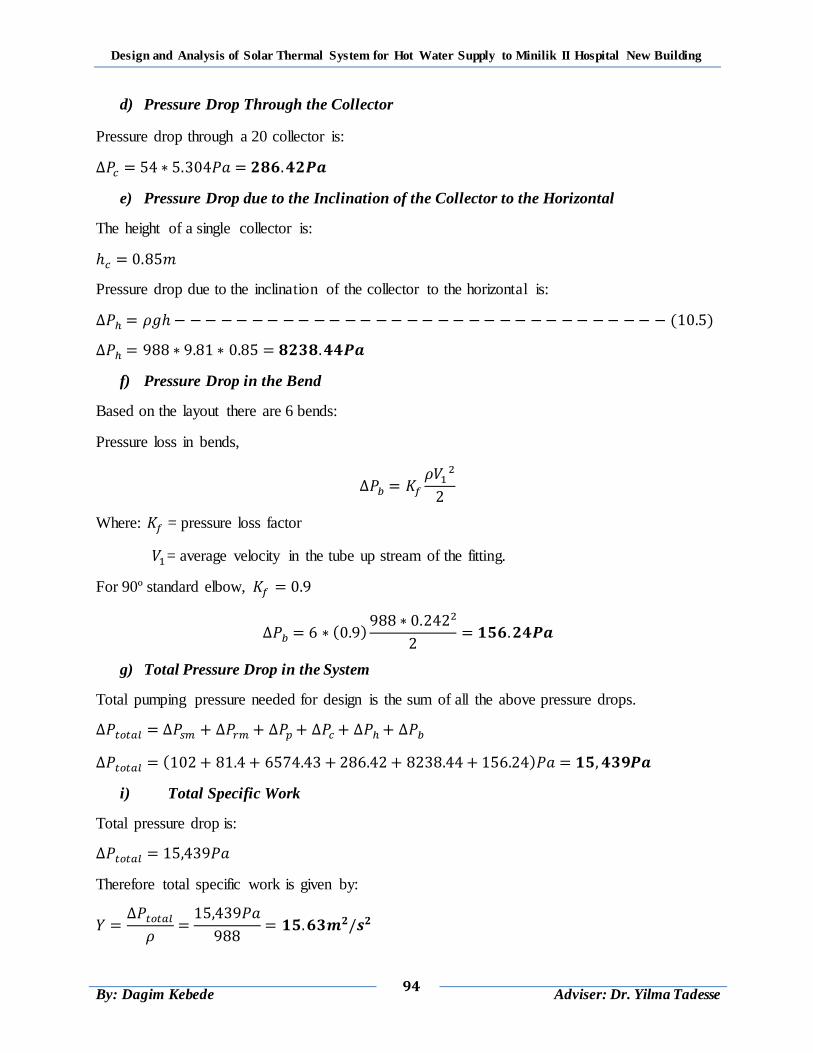
Design and Analysis of Solar Thermal System for Hot Water Supply to Minilik II Hospital New Building
94
By: Dagim Kebede
Adviser: Dr. Yilma Tadesse
d) Pressure Drop Through the Collector
Pressure drop through a 20 collector is:
e) Pressure Drop due to the Inclination of the Collector to the Horizontal
The height of a single collector is:
Pressure drop due to the inclination of the collector to the horizontal is:
( )
f) Pressure Drop in the Bend
Based on the layout there are 6 bends:
Pressure loss in bends,
Where: = pressure loss factor
= average velocity in the tube up stream of the fitting.
For 90º standard elbow,
( )
g) Total Pressure Drop in the System
Total pumping pressure needed for design is the sum of all the above pressure drops.
( )
i) Total Specific Work
Total pressure drop is:
Therefore total specific work is given by:
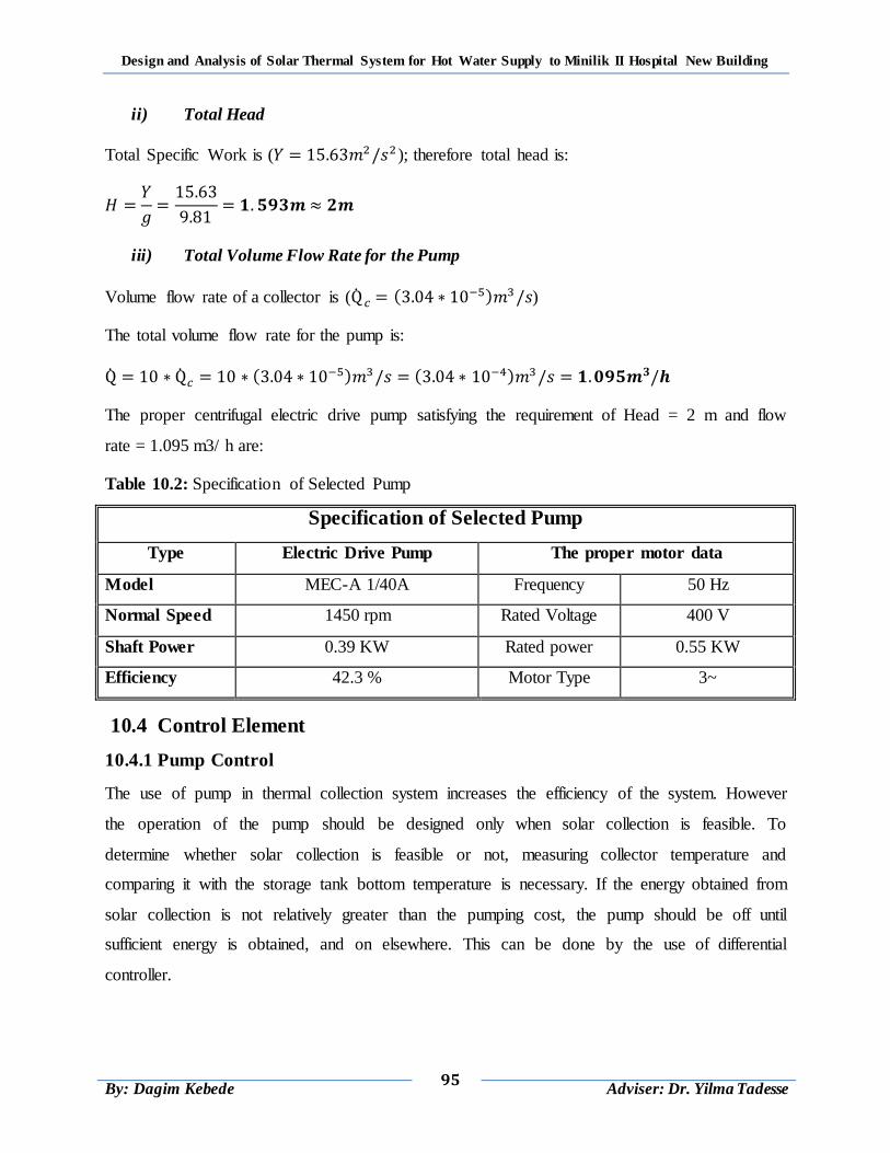
Design and Analysis of Solar Thermal System for Hot Water Supply to Minilik II Hospital New Building
95
By: Dagim Kebede
Adviser: Dr. Yilma Tadesse
ii) Total Head
Total Specific Work is ( ); therefore total head is:
iii) Total Volume Flow Rate for the Pump
Volume flow rate of a collector is ( ( ) )
The total volume flow rate for the pump is:
( ) ( )
The proper centrifugal electric drive pump satisfying the requirement of Head = 2 m and flow
rate = 1.095 m3/ h are:
Table 10.2: Specification of Selected Pump
Specification of Selected Pump
Type Electric Drive Pump The proper motor data
Model MEC-A 1/40A Frequency 50 Hz
Normal Speed 1450 rpm Rated Voltage 400 V
Shaft Power 0.39 KW Rated power 0.55 KW
Efficiency 42.3 % Motor Type 3~
10.4 Control Element
10.4.1 Pump Control
The use of pump in thermal collection system increases the efficiency of the system. However
the operation of the pump should be designed only when solar collection is feasible. To
determine whether solar collection is feasible or not, measuring collector temperature and
comparing it with the storage tank bottom temperature is necessary. If the energy obtained from
solar collection is not relatively greater than the pumping cost, the pump should be off until
sufficient energy is obtained, and on elsewhere. This can be done by the use of differential
controller.
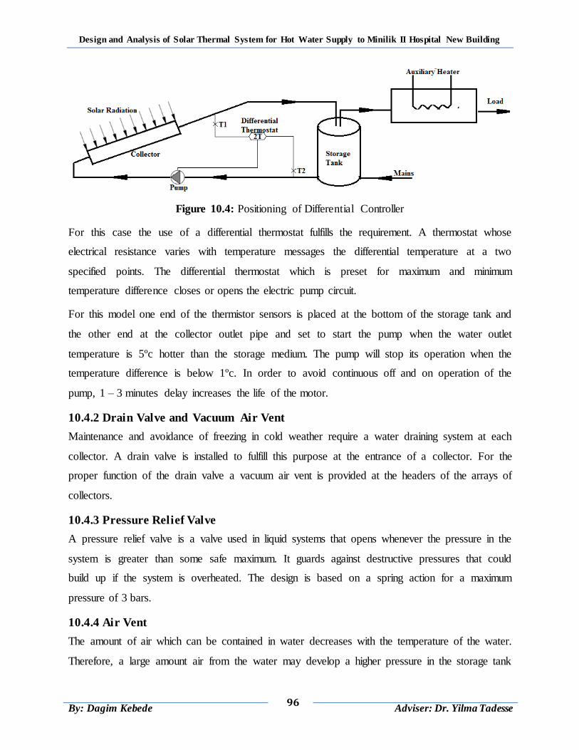
Design and Analysis of Solar Thermal System for Hot Water Supply to Minilik II Hospital New Building
96
By: Dagim Kebede
Adviser: Dr. Yilma Tadesse
Figure 10.4: Positioning of Differential Controller
For this case the use of a differential thermostat fulfills the requirement. A thermostat whose
electrical resistance varies with temperature messages the differential temperature at a two
specified points. The differential thermostat which is preset for maximum and minimum
temperature difference closes or opens the electric pump circuit.
For this model one end of the thermistor sensors is placed at the bottom of the storage tank and
the other end at the collector outlet pipe and set to start the pump when the water outlet
temperature is 5ºc hotter than the storage medium. The pump will stop its operation when the
temperature difference is below 1ºc. In order to avoid continuous off and on operation of the
pump, 1 – 3 minutes delay increases the life of the motor.
10.4.2 Drain Valve and Vacuum Air Vent
Maintenance and avoidance of freezing in cold weather require a water draining system at each
collector. A drain valve is installed to fulfill this purpose at the entrance of a collector. For the
proper function of the drain valve a vacuum air vent is provided at the headers of the arrays of
collectors.
10.4.3 Pressure Relief Valve
A pressure relief valve is a valve used in liquid systems that opens whenever the pressure in the
system is greater than some safe maximum. It guards against destructive pressures that could
build up if the system is overheated. The design is based on a spring action for a maximum
pressure of 3 bars.
10.4.4 Air Vent
The amount of air which can be contained in water decreases with the temperature of the water.
Therefore, a large amount air from the water may develop a higher pressure in the storage tank
Design and Analysis of Solar Thermal System for Hot Water Supply to Minilik II Hospital New Building
97
By: Dagim Kebede
Adviser: Dr. Yilma Tadesse
and the pipes. Therefore this air should be vented through an air vent. Air vent designed at the
header and top of the storage tank is in coincidence with a lighter density of air.
10.4.5 Check Valves
Check valves allow fluid to flow in only one direction. In solar systems, these valves prevent
thermosiphoning action in the system plumbing. Without a check valve, water that cools in the
elevated collector at night will fall by gravity to the storage tank, displacing lighter, warmer
water out of the storage tank and up to the collector. Once begun, this thermosiphoning action
can continue all night, continuously cooling all the water in the tank.
Corrosion and scale may build up on the internal components of a check valve; therefore, a
regular service schedule should be maintained.
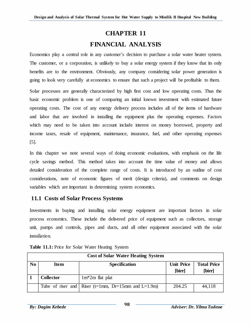
Design and Analysis of Solar Thermal System for Hot Water Supply to Minilik II Hospital New Building
98
By: Dagim Kebede
Adviser: Dr. Yilma Tadesse
CHAPTER 11
FINANCIAL ANALYSIS
Economics play a central role in any customer‟s decision to purchase a solar water heater system.
The customer, or a corporation, is unlikely to buy a solar energy system if they know that its only
benefits are to the environment. Obviously, any company considering solar power generation is
going to look very carefully at economics to ensure that such a project will be profitable to them.
Solar processes are generally characterized by high first cost and low operating costs. Thus the
basic economic problem is one of comparing an initial known investment with estimated future
operating costs. The cost of any energy delivery process includes all of the items of hardware
and labor that are involved in installing the equipment plus the operating expenses. Factors
which may need to be taken into account include interest on money borrowed, property and
income taxes, resale of equipment, maintenance, insurance, fuel, and other operating expenses
[5].
In this chapter we note several ways of doing economic evaluations, with emphasis on the life
cycle savings method. This method takes into account the time value of money and allows
detailed consideration of the complete range of costs. It is introduced by an outline of cost
considerations, note of economic figures of merit (design criteria), and comments on design
variables which are important in determining system economics.
11.1 Costs of Solar Process Systems
Investments in buying and installing solar energy equipment are important factors in solar
process economics. These include the delivered price of equipment such as collectors, storage
unit, pumps and controls, pipes and ducts, and all other equipment associated with the solar
installation.
Table 11.1: Price for Solar Water Heating System
Cost of Solar Water Heating System
No Item Specification Unit Price
[birr]
Total Price
[birr]
1 Collector 1m*2m flat plat
Tube of riser and Riser (t=1mm, Dr=15mm and L=1.9m) 204.25 44,118
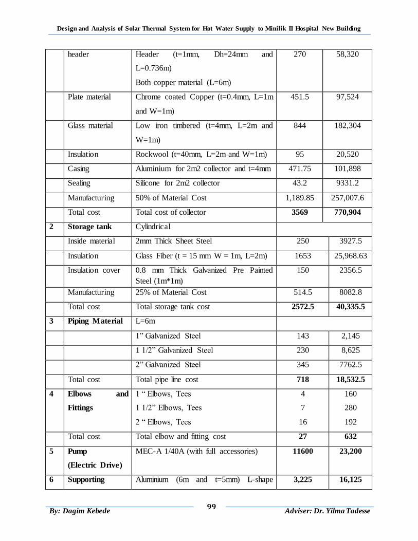
Design and Analysis of Solar Thermal System for Hot Water Supply to Minilik II Hospital New Building
99
By: Dagim Kebede
Adviser: Dr. Yilma Tadesse
header Header (t=1mm, Dh=24mm and
L=0.736m)
Both copper material (L=6m)
270 58,320
Plate material Chrome coated Copper (t=0.4mm, L=1m
and W=1m)
451.5 97,524
Glass material Low iron timbered (t=4mm, L=2m and
W=1m)
844 182,304
Insulation Rockwool (t=40mm, L=2m and W=1m) 95 20,520
Casing Aluminium for 2m2 collector and t=4mm 471.75 101,898
Sealing Silicone for 2m2 collector 43.2 9331.2
Manufacturing 50% of Material Cost 1,189.85 257,007.6
Total cost Total cost of collector 3569 770,904
2 Storage tank Cylindrical
Inside material 2mm Thick Sheet Steel 250 3927.5
Insulation Glass Fiber (t = 15 mm W = 1m, L=2m) 1653 25,968.63
Insulation cover 0.8 mm Thick Galvanized Pre Painted
Steel (1m*1m)
150 2356.5
Manufacturing 25% of Material Cost 514.5 8082.8
Total cost Total storage tank cost 2572.5 40,335.5
3 Piping Material L=6m
1” Galvanized Steel 143 2,145
1 1/2” Galvanized Steel 230 8,625
2” Galvanized Steel 345 7762.5
Total cost Total pipe line cost 718 18,532.5
4 Elbows and
Fittings
1 “ Elbows, Tees
1 1/2” Elbows, Tees
2 “ Elbows, Tees
4
7
16
160
280
192
Total cost Total elbow and fitting cost 27 632
5 Pump
(Electric Drive)
MEC-A 1/40A (with full accessories) 11600 23,200
6 Supporting Aluminium (6m and t=5mm) L-shape 3,225 16,125
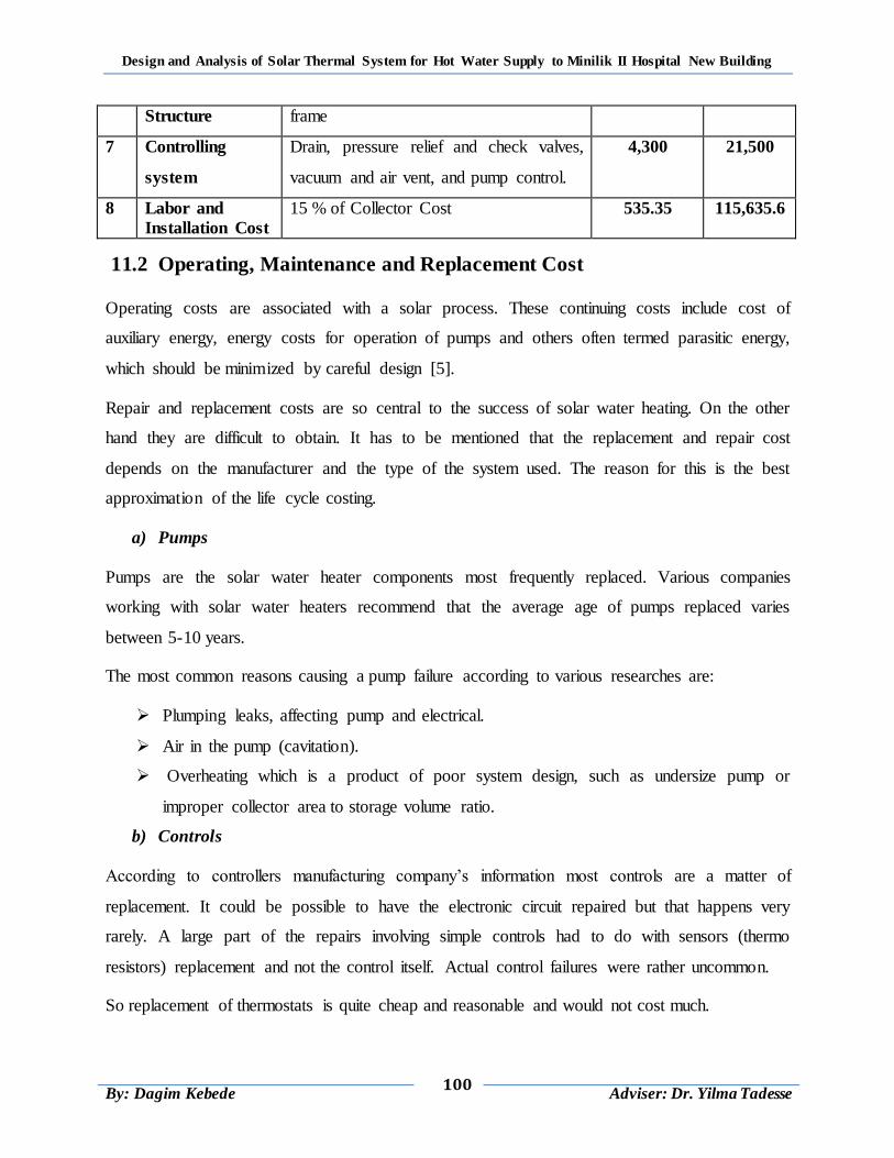
Design and Analysis of Solar Thermal System for Hot Water Supply to Minilik II Hospital New Building
100
By: Dagim Kebede
Adviser: Dr. Yilma Tadesse
Structure frame
7 Controlling
system
Drain, pressure relief and check valves,
vacuum and air vent, and pump control.
4,300 21,500
8 Labor and
Installation Cost 15 % of Collector Cost 535.35 115,635.6
11.2 Operating, Maintenance and Replacement Cost
Operating costs are associated with a solar process. These continuing costs include cost of
auxiliary energy, energy costs for operation of pumps and others often termed parasitic energy,
which should be minimized by careful design [5].
Repair and replacement costs are so central to the success of solar water heating. On the other
hand they are difficult to obtain. It has to be mentioned that the replacement and repair cost
depends on the manufacturer and the type of the system used. The reason for this is the best
approximation of the life cycle costing.
a) Pumps
Pumps are the solar water heater components most frequently replaced. Various companies
working with solar water heaters recommend that the average age of pumps replaced varies
between 5-10 years.
The most common reasons causing a pump failure according to various researches are:
Plumping leaks, affecting pump and electrical.
Air in the pump (cavitation).
Overheating which is a product of poor system design, such as undersize pump or
improper collector area to storage volume ratio.
b) Controls
According to controllers manufacturing company‟s information most controls are a matter of
replacement. It could be possible to have the electronic circuit repaired but that happens very
rarely. A large part of the repairs involving simple controls had to do with sensors (thermo
resistors) replacement and not the control itself. Actual control failures were rather uncommon.
So replacement of thermostats is quite cheap and reasonable and would not cost much.
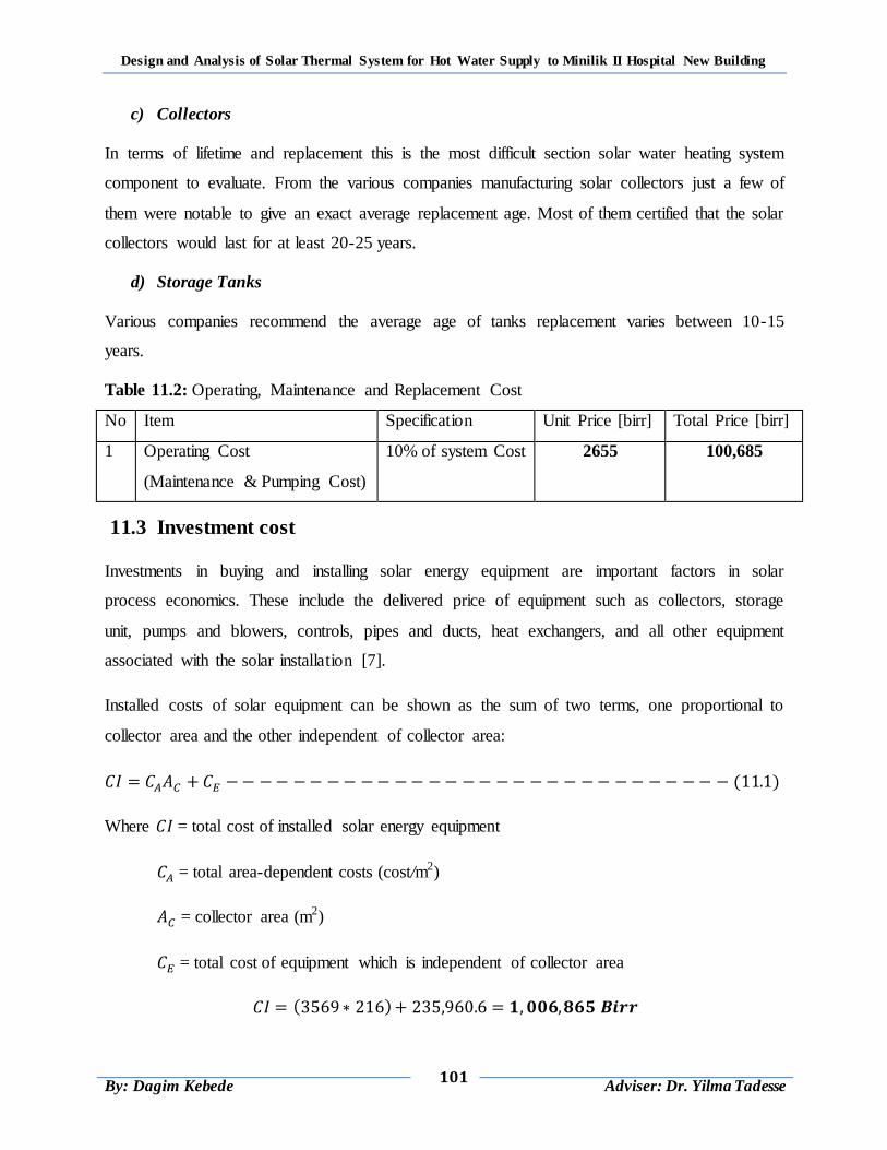
Design and Analysis of Solar Thermal System for Hot Water Supply to Minilik II Hospital New Building
101
By: Dagim Kebede
Adviser: Dr. Yilma Tadesse
c) Collectors
In terms of lifetime and replacement this is the most difficult section solar water heating system
component to evaluate. From the various companies manufacturing solar collectors just a few of
them were notable to give an exact average replacement age. Most of them certified that the solar
collectors would last for at least 20-25 years.
d) Storage Tanks
Various companies recommend the average age of tanks replacement varies between 10-15
years.
Table 11.2: Operating, Maintenance and Replacement Cost
No Item Specification Unit Price [birr] Total Price [birr]
1 Operating Cost
(Maintenance & Pumping Cost)
10% of system Cost 2655 100,685
11.3 Investment cost
Investments in buying and installing solar energy equipment are important factors in solar
process economics. These include the delivered price of equipment such as collectors, storage
unit, pumps and blowers, controls, pipes and ducts, heat exchangers, and all other equipment
associated with the solar installation [7].
Installed costs of solar equipment can be shown as the sum of two terms, one proportional to
collector area and the other independent of collector area:
( )
Where = total cost of installed solar energy equipment
= total area-dependent costs (cost/m2)
= collector area (m2)
= total cost of equipment which is independent of collector area
( )
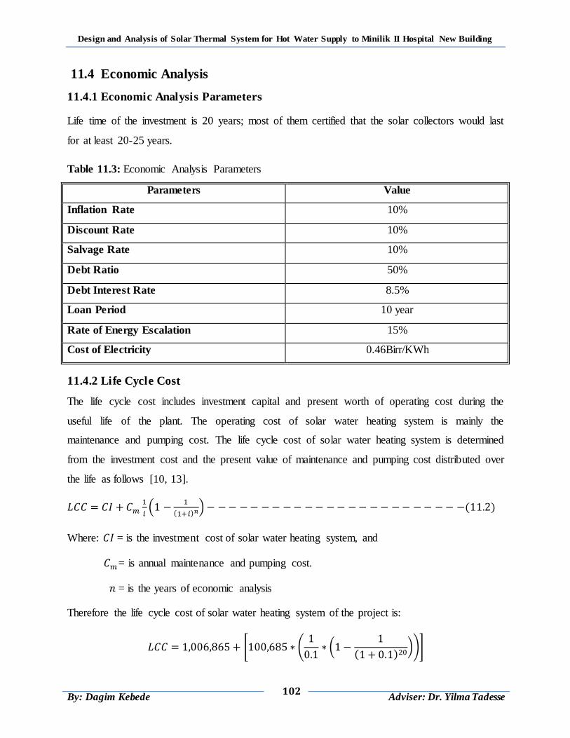
Design and Analysis of Solar Thermal System for Hot Water Supply to Minilik II Hospital New Building
102
By: Dagim Kebede
Adviser: Dr. Yilma Tadesse
11.4 Economic Analysis
11.4.1 Economic Analysis Parameters
Life time of the investment is 20 years; most of them certified that the solar collectors would last
for at least 20-25 years.
Table 11.3: Economic Analysis Parameters
Parameters Value
Inflation Rate 10%
Discount Rate 10%
Salvage Rate 10%
Debt Ratio 50%
Debt Interest Rate 8.5%
Loan Period 10 year
Rate of Energy Escalation 15%
Cost of Electricity 0.46Birr/KWh
11.4.2 Life Cycle Cost
The life cycle cost includes investment capital and present worth of operating cost during the
useful life of the plant. The operating cost of solar water heating system is mainly the
maintenance and pumping cost. The life cycle cost of solar water heating system is determined
from the investment cost and the present value of maintenance and pumping cost distributed over
the life as follows [10, 13].
(
( ) ) ( )
Where: = is the investment cost of solar water heating system, and
= is annual maintenance and pumping cost.
= is the years of economic analysis
Therefore the life cycle cost of solar water heating system of the project is:
0 .
(
( ) )/1
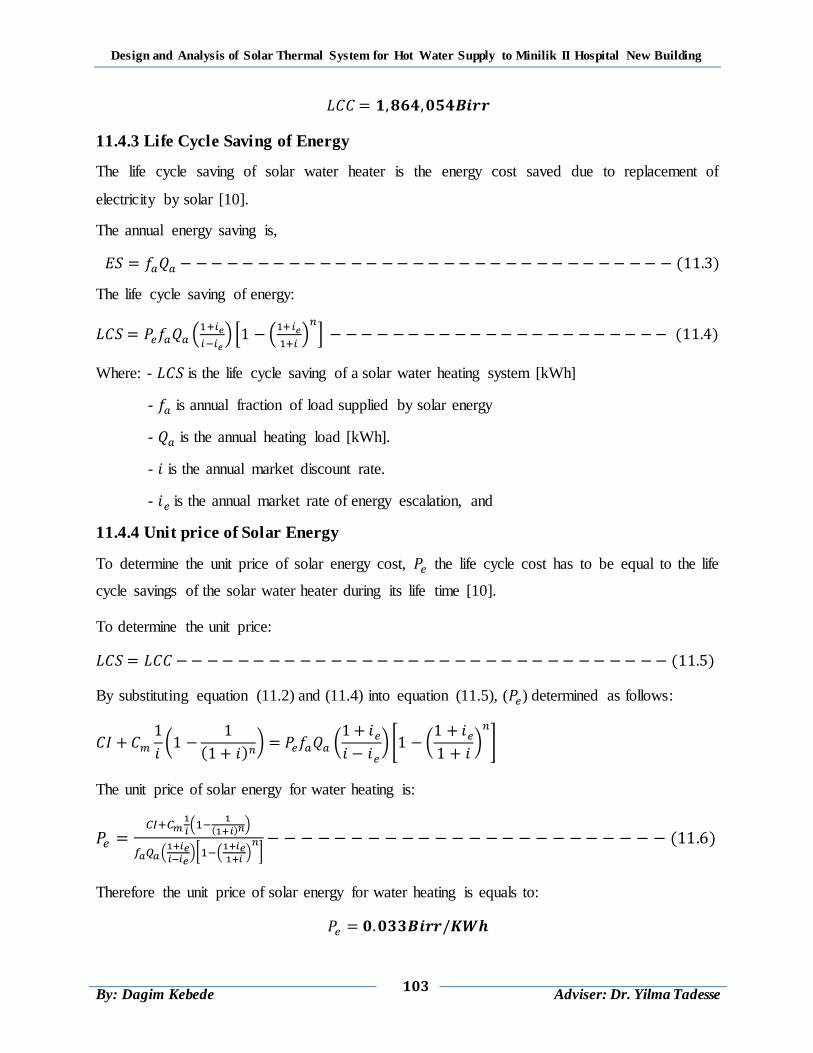
Design and Analysis of Solar Thermal System for Hot Water Supply to Minilik II Hospital New Building
103
By: Dagim Kebede
Adviser: Dr. Yilma Tadesse
11.4.3 Life Cycle Saving of Energy
The life cycle saving of solar water heater is the energy cost saved due to replacement of
electricity by solar [10].
The annual energy saving is,
( )
The life cycle saving of energy:
(
) * (
)
+ ( )
Where: - is the life cycle saving of a solar water heating system [kWh]
- is annual fraction of load supplied by solar energy
- is the annual heating load [kWh].
- is the annual market discount rate.
- is the annual market rate of energy escalation, and
11.4.4 Unit price of Solar Energy
To determine the unit price of solar energy cost, the life cycle cost has to be equal to the life
cycle savings of the solar water heater during its life time [10].
To determine the unit price:
( )
By substituting equation (11.2) and (11.4) into equation (11.5), ( ) determined as follows:
(
( ) ) (
) 0 (
)
1
The unit price of solar energy for water heating is:
(
( )
)
(
)[ (
) ] ( )
Therefore the unit price of solar energy for water heating is equals to:
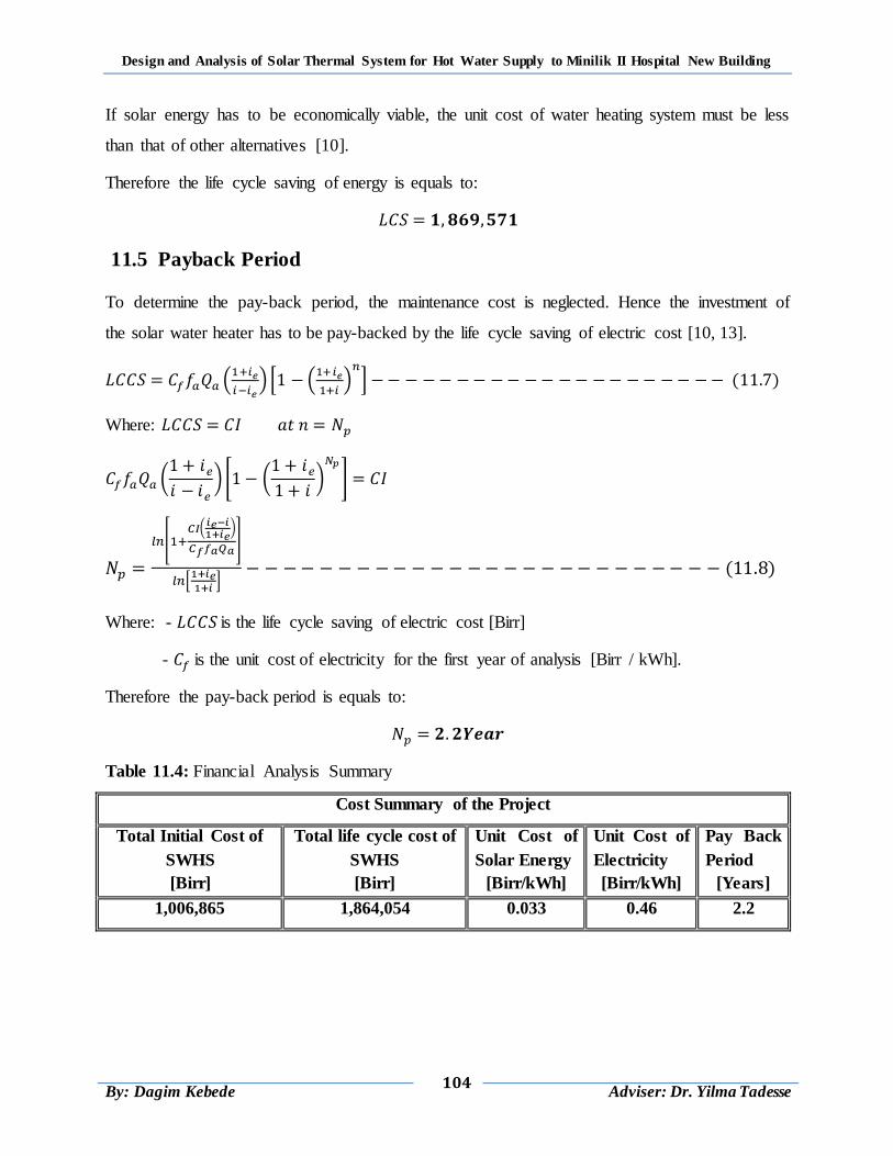
Design and Analysis of Solar Thermal System for Hot Water Supply to Minilik II Hospital New Building
104
By: Dagim Kebede
Adviser: Dr. Yilma Tadesse
If solar energy has to be economically viable, the unit cost of water heating system must be less
than that of other alternatives [10].
Therefore the life cycle saving of energy is equals to:
11.5 Payback Period
To determine the pay-back period, the maintenance cost is neglected. Hence the investment of
the solar water heater has to be pay-backed by the life cycle saving of electric cost [10, 13].
(
) * (
)
+ ( )
Where:
(
) 0 (
)
1
[ (
)
]
*
+ ( )
Where: - is the life cycle saving of electric cost [Birr]
- is the unit cost of electricity for the first year of analysis [Birr / kWh].
Therefore the pay-back period is equals to:
Table 11.4: Financial Analysis Summary
Cost Summary of the Project
Total Initial Cost of
SWHS
[Birr]
Total life cycle cost of
SWHS
[Birr]
Unit Cost of
Solar Energy
[Birr/kWh]
Unit Cost of
Electricity
[Birr/kWh]
Pay Back
Period
[Years]
1,006,865 1,864,054 0.033 0.46 2.2
Design and Analysis of Solar Thermal System for Hot Water Supply to Minilik II Hospital New Building
105
By: Dagim Kebede
Adviser: Dr. Yilma Tadesse
CHAPTER 12
CONCLUSIONS AND RECOMMENDATIONS
12.1 Conclusion
This project presents design and analysis of solar thermal system for Hot water supply to Minilik
II hospital new building. To achieve the objective of the study different approaches are
performed.
A detailed mathematical derivation for the flat-plate solar collector cross sections (glass cover,
absorber plate, water stream, and thermal storage tank) was presented. A one dimensional
mathematical model with distributed parameters that combines the solar collector‟s tank model
and the flat-plat model is derived to simulate the collector process. All the thermo-physical
properties of the water stream and the storage tank are computed in time dependent mode. The
transient heat transfer coefficients are also computed in real time.
To solve the derived system of equations, the implicit finite-difference scheme was suggested.
The proposed method allows the transient processes occur in the flat-plate solar collector to be
simulated. The time dependent flow rate, variable ambient temperature, and variable solar
irradiance have been taken in consideration. The proposed solution method was implemented by
utilizing the MATLAB software. The code mathematically solves the model and iteratively
evaluates the temperature histories for each analyzed cross section of the solar collector at any
selected point along the flow direction.
It was found that for Minilik II hospital of total daily hot water consumption of 30.475 m3, a total
of 108 collectors with two storage tanks of each capacity 18.3 m3 are needed with initial capital
cost of 1,006,865 Birr per project, which will cost a total of 1,864,054 Birr per project through-
out its life time and the life cycle cost saving will be Birr per project. The unit price
of solar thermal energy is 0.033 Birr per KWh and the payback period of the project is 2.2 year.
Since the unit cost of solar energy (0.033 Birr/KWh) is less than the unit cost of electricity (0.46
Birr/KWh) in Ethiopia, therefore water heating by solar energy is a viable alternative to heating
by electricity and fossil fuel (furnace oil).
Design and Analysis of Solar Thermal System for Hot Water Supply to Minilik II Hospital New Building
106
By: Dagim Kebede
Adviser: Dr. Yilma Tadesse
12.2 Recommendation
The following points can be recommended for the future work.
More experimental investigations are needed to confirm the performance and efficiency
of the proposed model, by testing the code for different cases.
The same work can also be done using parabolic trough collectors or vacuum tube
collectors system.
Parametric studies can be done using the flat-plate, vacuum tube or concentric type solar
collectors.
Optimizing of the solar thermal system.
Use of insulated pipe line for the collector to minimize the approximation error in the
ambient-pipe free convection coefficient.
Improving the running time of the code by using the inner product function instead of the
loops.
Design and Analysis of Solar Thermal System for Hot Water Supply to Minilik II Hospital New Building
107
By: Dagim Kebede
Adviser: Dr. Yilma Tadesse
REFERENCE
1. “Solar Thermal Combined Heat and Power Project at the Energy Resource Center”,
Southern California Gas Company, August 2014.
2. “Solar Thermal Systems: Solar Heating R&D”, U.S. Department of Energy Solar
Energy Technologies
3. Maxi Brochure 05: “Energy Efficiency in Hospitals”, December 2015.
4. Ministry of water and Energy, Ethiopian national energy policy, (2nd draft), Ethiopia
Addis Ababa, 2013, February.
5. Duffie, J. A. and Beckman W. A. (1991): Solar Engineering of Thermal Processes. 4th
edition, J. Wiley and Sons, New York.
6. Christopher A. Homola, PE: Solar Domestic Hot Water Heating Systems Design,
Installation and Maintenance.
7. Dimitrios Panapakidis: Solar Water Heating Systems Study Reliability, Quantitative
Survey and Life Cycle Cost Method, MSc. thesis, Department of Mechanical eng.,
University of Strathclyde in Glasgow.
8. John R. Howell, Richard B. Bannerot, Grary C. Vliet: Solar Thermal Energy System,
USA, 1982.
9. RAI, G.D.: Solar Energy Utilization, fifth edition, Delhi, 2001.
10. Demiss Alemu: Optimal Design of Solar Water Heating System, Zede, No.15, Addis
Ababa, 1998.
11. Vonal.com (Manufacturer of Flat-Plate Solar Collectors in Ethiopia).
12. Yunus A. Cengel: Heat Transfer an Engineering Approach, 5th edition.
13. Collares-Pereira, Gordan, J. M., Rabi and Zarmi, Y.: Design and Optimization of Solar
Industrial Hot Water System, Solar Energy, Vol. 32, 1984.
14. Abebayehu Assefa and Demiss Alemu : The Viability of Solar Energy for Domestic
Water Heating in Ethiopian Cities, Zede, No.9, Addis Ababa, 1992.
15. Alternative Energy Sources (AES): „‟solar heating‟‟ (accessed: 09-02-2011) www.hk-
phy.org/energy/alternate/.../act_water_heating_e.htm. (2008),
16. ASHRAE (1995): „‟Handbook of Heating and Ventilation of Air Conditioning
Applications”, Atlanta.
Design and Analysis of Solar Thermal System for Hot Water Supply to Minilik II Hospital New Building
108
By: Dagim Kebede
Adviser: Dr. Yilma Tadesse
17. Benz N, Gut M, and Rub W.: Solar process heat in breweries and dairies , Portoroz,
Slovenia: Eurosun 1998; 1998.
18. Brandemuehl, M.J. and Beckman, W.A.: Economic Evaluation and Optimization of
Solar Water heating Systems, Solar Energy, Vol. 23, No. 1, 1979.
19. Fisch, M.N., Guigas, M. and Dalenback, J.O.: A Review of Large-Scale Solar Heating
System in Europe, Solar Energy, Vol. 63, No. 6, pp. 355-366, 1998.
20. Hottel, H.C. and Woertz, B.B.: Performance of Flat-Plate Solar-Heat Collectors,
Trans. ASME, 64, 91 (1942).
21. „„International Journal of Climatology‟‟, 26: 75–89 (2006), Published online 7
November 2005 in Wiley Inter Science (www.interscience.wiley.com).
22. “Introduction to Solar Thermal”, Sun Water Solar.
23. Kalogirou S. A. (2003): The potential of solar industrial process heat applications”.
Application Energy, pp76:337–61.
24. Lex Bosselaar and He Zinian: “Integration of Solar Water Heating into Residential
Building”, September 2014.
25. Sodha, M.S., Tiwari, G.N., Sawhney, R.L., Sharma, A.K., Singh, A.K. and Goya, R.K.:
Sizing of a Multi-Tank Solar Water Heater, Int. J. Energy Res., 22, 777 - 790 (1998),
India.
26. “The Potential of Solar Heat in the Future Energy System” Faculty for
Interdisciplinary Research and Continuing Education, IFF-University of Klagenfurt,
Austria(E-mail: gerhard.faninger@uni -klu.ac.at )
27. Tsilingiris, P.T.: Solar Water-Heating Design – A New Simplified Dynamic
Approach, Solar Energy, Vol. 57, No. 1 pp. 19-28,1996.
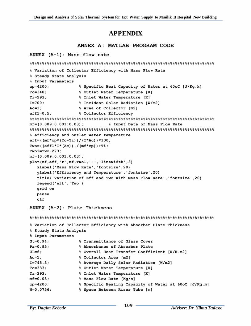
Design and Analysis of Solar Thermal System for Hot Water Supply to Minilik II Hospital New Building
109
By: Dagim Kebede
Adviser: Dr. Yilma Tadesse
APPENDIX
ANNEX A: MATLAB PROGRAM CODE
ANNEX (A-1): Mass flow rate
%%%%%%%%%%%%%%%%%%%%%%%%%%%%%%%%%%%%%%%%%%%%%%%%%%%%%%%%%%%%%%%%%%%%%%%%%%%
% Variation of Collector Efficiency with Mass Flow Rate
% Steady State Analysis
% Input Parameters
cp=4200; % Specific Heat Capacity of Water at 60oC [J/Kg.k]
To=340; % Outlet Water Temperature [K]
Ti=293; % Inlet Water Temperature [K]
I=700; % Incident Solar Radiation [W/m2]
Ac=1; % Area of Collector [m2]
eff1=0.5; % Collector Efficiency
%%%%%%%%%%%%%%%%%%%%%%%%%%%%%%%%%%%%%%%%%%%%%%%%%%%%%%%%%%%%%%%%%%%%%%%%%%%
mf=(0.009:0.001:0.03); % Input Data of Mass Flow Rate
%%%%%%%%%%%%%%%%%%%%%%%%%%%%%%%%%%%%%%%%%%%%%%%%%%%%%%%%%%%%%%%%%%%%%%%%%%%
% efficiency and outlet water temperature
eff=((mf*cp*(To-Ti))/(I*Ac))*100;
Two=((eff1*I*(Ac))./(mf*cp))+Ti;
Two1=Two-273;
mf=(0.009:0.001:0.03);
plot(mf,eff,'r',mf,Two1,'-','linewidth',3)
xlabel('Mass Flow Rate','fontsize',20)
ylabel('Efficiency and Temperature','fontsize',20)
title('Variation of Eff and Two with Mass Flow Rate','fontsize',20)
legend('eff','Two')
grid on
pause
clf
ANNEX (A-2): Plate Thickness
%%%%%%%%%%%%%%%%%%%%%%%%%%%%%%%%%%%%%%%%%%%%%%%%%%%%%%%%%%%%%%%%%%%%%%%%%%%
% Variation of Collector Efficiency with Absorber Plate Thickness
% Steady State Analysis
% Input Parameters
Gt=0.94; % Transmittance of Glass Cover
Pa=0.95; % Absorbance of Absorber Plate
UL=6; % Overall Heat Transfer Coefficient [W/K.m2]
Ac=1; % Collector Area [m2]
I=745.3; % Average Daily Solar Radiation [W/m2]
To=333; % Outlet Water Temperature [K]
Ta=293; % Inlet Water Temperature [K]
mf=0.03; % Mass Flow Rate [Kg/s]
cp=4200; % Specific Heating Capacity of Water at 60oC [J/Kg.m]
W=0.0756; % Space Between Riser Tube [m]

Design and Analysis of Solar Thermal System for Hot Water Supply to Minilik II Hospital New Building
110
By: Dagim Kebede
Adviser: Dr. Yilma Tadesse
Di=0.015; % Inner Diameter of Riser Tube [m]
Do=Di+0.001; % Outer Diameter of Riser Tube [m]
hfi=1500; % Heat Transfer Coefficient Inside the Tube [W/oC.m2]
k=401; % Thermal Conductivity of Plate [J/K.m]
%Plate Thickness Data Input
load pla.m;
data1=zeros(24,1,5);
for j=1:5
data1(:,:,j)=pla(j+(23*(j-1)):j*24,:);
end
%%%%%%%%%%%%%%%%%%%%%%%%%%%%%%%%%%%%%%%%%%%%%%%%%%%%%%%%%%%%%%%%%%%%%%%%%%%
Eff1=zeros(24,5);
% main program
for i=1:5
t=data1(:,1,i);
for j=1:24
tp=t(j);
m=sqrt(UL./(k*tp));
F=(tanh(m*((W-Do)/2)))/(m*((W-Do)/2));
F2=(1/UL)/(W*((1./(UL*(Do+((W-Do)*F))))+(1/(pi*hfi*Di))));
FR=((mf*cp)/(Ac*UL))*(1-(exp((-Ac*UL*F2)/(mf*cp))));
Eff=(FR*Gt*Pa)-((UL*FR*(To-Ta))/(Ac*I));
% Efficiency stored as;
Eff1(j,i)=Eff*100;
end
end
% store
Eff11=Eff1(:,1);
j=1:24;
plot(j,Eff11,'k','linewidth',3)
xlabel('Plate Thickness (mm)','fontsize',16)
ylabel('Efficiency','fontsize',16)
title('Variation of Efficiency with Plate Thickness','fontsize',16)
legend('Eff')
grid on
pause
clf
ANNEX (A-3): Riser Tube Inner Diameter
%%%%%%%%%%%%%%%%%%%%%%%%%%%%%%%%%%%%%%%%%%%%%%%%%%%%%%%%%%%%%%%%%%%%%%%%%%%
% Efficiency, Pressure Drop and Velocity with Header Tube Diameter
% Steady State Analysis
% Input Parameters
Gt=0.94; % Transmittance of Glass Cover
Pa=0.95; % Absorbance of Plate
UL=6; % Overall All Heat Transfer Coefficient [W/K.m2]
Ac=1; % Collector Area [m2]
I=745.3; % Average Daily Solar Radiation [W/m2]
To=333; % Outlet Water Temperature [K]

Design and Analysis of Solar Thermal System for Hot Water Supply to Minilik II Hospital New Building
111
By: Dagim Kebede
Adviser: Dr. Yilma Tadesse
Ta=293; % Inlet Water Temperature [K]
mf=0.03; % Mass Flow Rate [Kg/s]
cp=4200; % Specific Heating Capacity of Water at 60oC [J/Kg.m]
tp=0.0004; % Plate Thickness [m]
Wdens=988; % Density of Water at 60oC [Kg/m3]
mu=5.47e-4; % Dynamic Viscosity of Water at 60oC [m2/s]
L=1.8; % Length of Riser Tube [m]
hfi=1500; % Heat Transfer Coefficient Inside the Tube [W/oC.m2]
k=401; % Thermal Conductivity of Plate [J/K.m]
N1=10; % Number of Riser Tube
% Inner Diameter of Riser Tube data input
load nrt.m;
data1=zeros(15,1,1);
for j=1
data1(:,:,j)=nrt(j+(14*(j-1)):j*15,:);
end
%%%%%%%%%%%%%%%%%%%%%%%%%%%%%%%%%%%%%%%%%%%%%%%%%%%%%%%%%%%%%%%%%%%%%%%%%%%
Eff1=zeros(15,1);
Pr1=zeros(15,1);
Vavr1=zeros(15,1);
% main program
for i=1
D=data1(:,1,i);
for j=1:15
Di=D(j);
Do=Di1+0.001;
W=(0.81-Do)/9;
Ar=(pi*(Di1^2))/4;
Vfr=(mf/Wdens)/N;
Vavr=Vfr/Ar;
Re=(Wdens*Vavr*Di1)/mu;
f=64/Re;
Pr=f*(L/Di1)*((Wdens*(Vavr^2))/2);
m=sqrt(UL./(k*tp));
F=(tanh(m*((W-Do)/2)))/(m*((W-Do)/2));
F2=(1/UL)/(W*((1./(UL*(Do+((W-Do)*F))))+(1./(pi*hfi*Di1))));
FR=((mf*cp)/(Ac*UL))*(1-(exp((-Ac*UL*F2)/(mf*cp))));
Eff=(FR*Gt*Pa)-((UL*FR*(To-Ta))/(Ac*I));
% Efficiency stored as;
Eff1(j,i)=Eff*100;
Pr1(j,i)=Pr;
Vavr1(j,i)=Vavr*10000;
end
end
% store
Eff11=Eff1(:,1);
Pr11=Pr1(:,1);
Vavr11=Vavr1(:,1);
j=1:15;
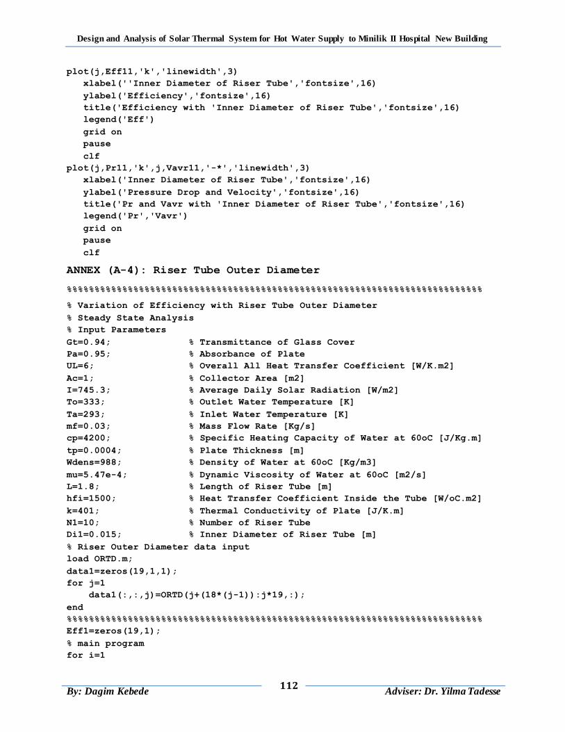
Design and Analysis of Solar Thermal System for Hot Water Supply to Minilik II Hospital New Building
112
By: Dagim Kebede
Adviser: Dr. Yilma Tadesse
plot(j,Eff11,'k','linewidth',3)
xlabel(''Inner Diameter of Riser Tube','fontsize',16)
ylabel('Efficiency','fontsize',16)
title('Efficiency with 'Inner Diameter of Riser Tube','fontsize',16)
legend('Eff')
grid on
pause
clf
plot(j,Pr11,'k',j,Vavr11,'-*','linewidth',3)
xlabel('Inner Diameter of Riser Tube','fontsize',16)
ylabel('Pressure Drop and Velocity','fontsize',16)
title('Pr and Vavr with 'Inner Diameter of Riser Tube','fontsize',16)
legend('Pr','Vavr')
grid on
pause
clf
ANNEX (A-4): Riser Tube Outer Diameter
%%%%%%%%%%%%%%%%%%%%%%%%%%%%%%%%%%%%%%%%%%%%%%%%%%%%%%%%%%%%%%%%%%%%%%%%%%%
% Variation of Efficiency with Riser Tube Outer Diameter
% Steady State Analysis
% Input Parameters
Gt=0.94; % Transmittance of Glass Cover
Pa=0.95; % Absorbance of Plate
UL=6; % Overall All Heat Transfer Coefficient [W/K.m2]
Ac=1; % Collector Area [m2]
I=745.3; % Average Daily Solar Radiation [W/m2]
To=333; % Outlet Water Temperature [K]
Ta=293; % Inlet Water Temperature [K]
mf=0.03; % Mass Flow Rate [Kg/s]
cp=4200; % Specific Heating Capacity of Water at 60oC [J/Kg.m]
tp=0.0004; % Plate Thickness [m]
Wdens=988; % Density of Water at 60oC [Kg/m3]
mu=5.47e-4; % Dynamic Viscosity of Water at 60oC [m2/s]
L=1.8; % Length of Riser Tube [m]
hfi=1500; % Heat Transfer Coefficient Inside the Tube [W/oC.m2]
k=401; % Thermal Conductivity of Plate [J/K.m]
N1=10; % Number of Riser Tube
Di1=0.015; % Inner Diameter of Riser Tube [m]
% Riser Outer Diameter data input
load ORTD.m;
data1=zeros(19,1,1);
for j=1
data1(:,:,j)=ORTD(j+(18*(j-1)):j*19,:);
end
%%%%%%%%%%%%%%%%%%%%%%%%%%%%%%%%%%%%%%%%%%%%%%%%%%%%%%%%%%%%%%%%%%%%%%%%%%%
Eff1=zeros(19,1);
% main program
for i=1

Design and Analysis of Solar Thermal System for Hot Water Supply to Minilik II Hospital New Building
113
By: Dagim Kebede
Adviser: Dr. Yilma Tadesse
D=data1(:,1,i);
for j=1:19
Do=D(j);
W=(0.81-Do)/9;
m=sqrt(UL./(k*tp));
F=(tanh(m*((W-Do)/2)))/(m*((W-Do)/2));
F2=(1/UL)/(W*((1./(UL*(Do+((W-Do)*F))))+(1./(pi*hfi*Di1))));
FR=((mf*cp)/(Ac*UL))*(1-(exp((-Ac*UL*F2)/(mf*cp))));
Eff=(FR*Gt*Pa)-((UL*FR*(To-Ta))/(Ac*I));
% Efficiency stored as;
Eff1(j,i)=Eff*100;
end
end
% store
Eff11=Eff1(:,1);
j=1:19;
plot(j,Eff11,'k','linewidth',3)
xlabel('Outer Diameter of Riser (mm)','fontsize',16)
ylabel('Efficiency','fontsize',16)
title('Efficiency with Outer Diameter of Riser','fontsize',16)
legend('Eff')
grid on
pause
clf
ANNEX (A-5): Number of Riser Tube
%%%%%%%%%%%%%%%%%%%%%%%%%%%%%%%%%%%%%%%%%%%%%%%%%%%%%%%%%%%%%%%%%%%%%%%%%%%
% Variation of Pressure Drop and Velocity with Number of Riser Tube
% Stady State Analysis
% Input Parameters
mf=0.03; % Mass Flow Rate [Kg/s]
Wdens=988; % Density of Water at 60oC [Kg/m3]
mu=5.47e-4; % Dynamic Vescociyt of Water at 60oC [m2/s]
L=0.736; % Length of Header Tube [m]
N1=10; % Number of Riser Tube
Di=0.015; % Inner Diameter of Riser Tube [m]
%Number of Riser Tube data input
load nrt.m;
data1=zeros(15,1,1);
for j=1
data1(:,:,j)=nrt(j+(14*(j-1)):j*15,:);
end
%%%%%%%%%%%%%%%%%%%%%%%%%%%%%%%%%%%%%%%%%%%%%%%%%%%%%%%%%%%%%%%%%%%%%%%%%%%
Pr1=zeros(15,1);
Vavr1=zeros(15,1);
% main program
for i=1
n=data1(:,1,i);
for j=1:15

Design and Analysis of Solar Thermal System for Hot Water Supply to Minilik II Hospital New Building
114
By: Dagim Kebede
Adviser: Dr. Yilma Tadesse
N=n(j);
Ar=(pi*(Di^2))/4;
Vfr=(mf/Wdens)/N;
Vavr=Vfr/Ar;
Re=(Wdens*Vavr*Di1)/mu;
f=64/Re;
Pr=f*(L/Di1)*((Wdens*(Vavr^2))/2);
% Pressure Drop and Velocity stored as;
Pr1(j,i)=Pr;
Vavr1(j,i)=Vavr*10000;
end
end
% store
Pr11=Pr1(:,1);
Vavr11=Vavr1(:,1);
j=1:15;
plot(j,Pr11,'k',j,Vavr11,'-*','linewidth',3)
xlabel('Number of Riser Tube','fontsize',16)
ylabel('Pressure Drop and Velocity','fontsize',16)
title('Pr and Vavr with Number of Riser Tube','fontsize',16)
legend('Pr','Vavr')
grid on
pause
clf
ANNEX (A-6): Header Tube Diameter
%%%%%%%%%%%%%%%%%%%%%%%%%%%%%%%%%%%%%%%%%%%%%%%%%%%%%%%%%%%%%%%%%%%%%%%%%%%
% Variation of Pressure Drop and Velocity with Header Tube Diameter
% Steady State Analysis
% Input Parameters
mf=0.03; % Mass Flow Rate [Kg/s]
Wdens=988; % Density of Water at 60oC [Kg/m3]
mu=5.47e-4; % Dynamic Viscosity of Water at 60oC [m2/s]
L=0.736; % Length of Header Tube [m]
%Header Tube data input
load head.m;
data1=zeros(24,1,2);
for j=1:2
data1(:,:,j)=head(j+(23*(j-1)):j*24,:);
end
%%%%%%%%%%%%%%%%%%%%%%%%%%%%%%%%%%%%%%%%%%%%%%%%%%%%%%%%%%%%%%%%%%%%%%%%%%%
Ph1=zeros(24,2);
Vavh1=zeros(24,2);
% main program
for i=1:2
Dhh=data1(:,1,i);
for j=1:24
Dh=Dhh(j);
Ah=(pi*(Dh^2))/4;
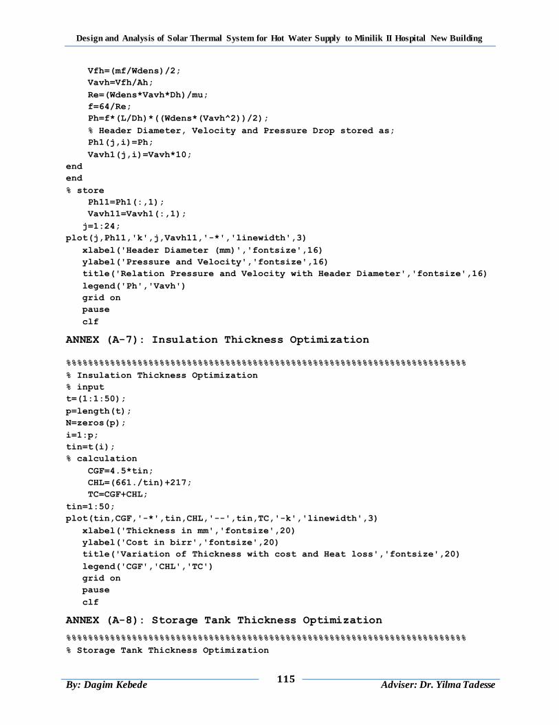
Design and Analysis of Solar Thermal System for Hot Water Supply to Minilik II Hospital New Building
115
By: Dagim Kebede
Adviser: Dr. Yilma Tadesse
Vfh=(mf/Wdens)/2;
Vavh=Vfh/Ah;
Re=(Wdens*Vavh*Dh)/mu;
f=64/Re;
Ph=f*(L/Dh)*((Wdens*(Vavh^2))/2);
% Header Diameter, Velocity and Pressure Drop stored as;
Ph1(j,i)=Ph;
Vavh1(j,i)=Vavh*10;
end
end
% store
Ph11=Ph1(:,1);
Vavh11=Vavh1(:,1);
j=1:24;
plot(j,Ph11,'k',j,Vavh11,'-*','linewidth',3)
xlabel('Header Diameter (mm)','fontsize',16)
ylabel('Pressure and Velocity','fontsize',16)
title('Relation Pressure and Velocity with Header Diameter','fontsize',16)
legend('Ph','Vavh')
grid on
pause
clf
ANNEX (A-7): Insulation Thickness Optimization
%%%%%%%%%%%%%%%%%%%%%%%%%%%%%%%%%%%%%%%%%%%%%%%%%%%%%%%%%%%%%%%%%%%%%%%%%
% Insulation Thickness Optimization
% input
t=(1:1:50);
p=length(t);
N=zeros(p);
i=1:p;
tin=t(i);
% calculation
CGF=4.5*tin;
CHL=(661./tin)+217;
TC=CGF+CHL;
tin=1:50;
plot(tin,CGF,'-*',tin,CHL,'--',tin,TC,'-k','linewidth',3)
xlabel('Thickness in mm','fontsize',20)
ylabel('Cost in birr','fontsize',20)
title('Variation of Thickness with cost and Heat loss','fontsize',20)
legend('CGF','CHL','TC')
grid on
pause
clf
ANNEX (A-8): Storage Tank Thickness Optimization
%%%%%%%%%%%%%%%%%%%%%%%%%%%%%%%%%%%%%%%%%%%%%%%%%%%%%%%%%%%%%%%%%%%%%%%%%
% Storage Tank Thickness Optimization
Design and Analysis of Solar Thermal System for Hot Water Supply to Minilik II Hospital New Building
116
By: Dagim Kebede
Adviser: Dr. Yilma Tadesse
% input
t=(0:10);
p=length(t);
N=zeros(p);
i=1:p;
ts=(t(i));
% calculation
CMSP=100.*ts;
CHL=(697./ts)+342;
TC=CMSP+CHL;
ts=0:10;
plot(ts,CMSP,'-*',ts,CHL,'--',ts,TC,'-k','linewidth',3)
xlabel('Thickness in mm','fontsize',20)
ylabel('Cost in birr','fontsize',20)
title('Variation of Thickness with cost and Heat loss','fontsize',20)
legend('CMSP','CHL','TC')
grid on
pause
clf
ANNEX (A-9): Transient Analysis of Temperature
%%%%%%%%%%%%%%%%%%%%%%%%%%%%%%%%%%%%%%%%%%%%%%%%%%%%%%%%%%%%%%%%%%%%%%%%%%
% Hourly Temperature Variation of Water Stream and Storage Tank
% Given Global Radiation and Ambient Temperature Values for a Year
% Consider a Single Glass Cover and Absorber Plate
% Design Parameters
ts=0.0025; % Storage Tank Thickness [ m ]
tsin=0.015; % Storage Insulation Thickness [ m ]
Lt=2; % Length of Collector [ m ]
Lin=0.05; % Insulation Thickness [ m ]
tp=0.0005; % Plate Thickness [ m ]
di=0.015; % Inner Diameter of Riser Tube [m]
ds=2.3; % Diameter of Storage Tank [m]
Aa=2; % Absorber Plate Area [ m2 ]
Ae=0.24; % Collector Edge Area [ m2 ]
Aw=0.895; % Riser Tube Surface Area [ m2 ]
As=41.55; % Storage Tank Surface area [ m2 ]
Vs=12.2; % Storage Tank Volume [ m3 ]
Gabso=0.02; % Absorivity of Glass
Pabso=0.95; % Absorivity of Plate
Tabso=0.95; % Absorivity of Riser Tube
Gtrans=0.94; % Transmissivity of Glass
rho=0.2; % Ground Reflectivity Factor
Ep=0.03; % Emissivity of Plate
Eg=0.04; % Emissivity of Glass
Vw=3; % Wind Speed [ m/s ]
sigma=5.67e-8; % Boltzmann Constant [ W/m2K4 ]
tpg=0.03; % Distance b/n Glass and Plate [ m ]
phi=9.03*(pi/180); % Latitude of Addis Ababa (Minilik II) [ rad ]

Design and Analysis of Solar Thermal System for Hot Water Supply to Minilik II Hospital New Building
117
By: Dagim Kebede
Adviser: Dr. Yilma Tadesse
beta=22*(pi/180); % Collector Slope (South Facing) [ rad ]
mg=18.8; % Mass of Glass [ Kg ]
mp=8.933; % Mass of Plate [ Kg ]
mw=1.3; % Mass of Water [ Kg ]
mf=0.03; % Mass Flow Rate of a Water [ m/s ]
mfs=0.6; % Mass Flow Rate to Storage Tank [ m/s ]
cpw=4180; % Sp.Heat of Water [ J/Kg.K ]
cpp=8933; % Sp.Heat of Plate [ J/Kg.k ]
cpg=840; % Sp.Heat of glass [ J/Kg.K ]
kg=1.7; % Thermal Conductivity of Glass [ W/mK ]
ka=0.03; % Thermal Conductivity of Air [ W/m2K ]
kin=0.037; % Thermal Conductivity of Insulation [ W/m2K ]
kw=0.625; % Thermal Conductivity of Water [ W/m2K ]
ks=0.036; % Thermal Conductivity of Storage Tank [ W/mK ]
ksin=0.032; % Thermal Conductivity of Storage Insulation [ W/mK ]
kp=401; % Thermal Conductivity of Plate [ W/mK ]
prw=4.772; % Prantdl Number of Water
pr=0.708; % Prantdl Number of Air
Re=733; % Reynolds Number
dv=1.754e-5; % Dynamic Viscosity of Water [ Kg/ms ]
g=9.81; % Gravity [ m.s2 ]
Nuinf=4.4; % Nusselt Number @ Infinity
a=0.00398; % Nusselt Number Constant
b=0.0114; % Nusselt Number Constant
m=1.6; % Nusselt Number Constant
n=1.12; % Nusselt Number Constant
W=0.08; % Space B/n Riser Tubes [ m ]
D=0.016; % Outer Diameter of Riser Tubes [ m ]
hfi=1500; % Heat Transfer Coefficient Inside the Tube [ W/oC.m2]
N=10; % Number of Riser Tube
Wdens=988; % Density of Water [ Kg/m3 ]
deltt=60; % Time Step
%%%%%%%%%%%%%%%%%%%%%%%%%%%%%%%%%%%%%%%%%%%%%%%%%%%%%%%%%%%%%%%%%%%%%%%%%%
%solar radiation data input
load SolDat.m;
data1=zeros(24,3);
for j=1:365
data1(:,:,j)=SolDat(j+(23*(j-1)):j*24,:);
end
%%%%%%%%%%%%%%%%%%%%%%%%%%%%%%%%%%%%%%%%%%%%%%%%%%%%%%%%%%%%%%%%%%%%%%%%%%
Tp=zeros(24,365);Tp1=zeros(24,365);Tp2=zeros(24,365);Tp3=zeros(24,365);
Tg=zeros(24,365);Tg1=zeros(24,365);Tg2=zeros(24,365);Tg3=zeros(24,365);
Two=zeros(24,365);Two1=zeros(24,365);Two2=zeros(24,365);Two3=zeros(24,365);
Ts=zeros(24,365);Ts1=zeros(24,365);Ts2=zeros(24,365);Ts3=zeros(24,365);
Upw1=zeros(24,365);Upw2=zeros(24,365);UL1=zeros(24,365);ULs1=zeros(24,365);
UL2=zeros(24,365);ULs2=zeros(24,365);It1=zeros(24,365);It2=zeros(24,365);
Ic1=zeros(24,365);Ic2=zeros(24,365);Qu1=zeros(24,365);Ef1=zeros(24,365);
%%%%%%%%%%%%%%%%%%%%%%%%%%%%%%%%%%%%%%%%%%%%%%%%%%%%%%%%%%%%%%%%%%%%%%%%%%
% Sun Basic Angles
Design and Analysis of Solar Thermal System for Hot Water Supply to Minilik II Hospital New Building
118
By: Dagim Kebede
Adviser: Dr. Yilma Tadesse
% Declination Angle(Deltt)of the sun every day over the year
for j=1:365
decl(j)=(pi/180)*(23.45*sin((2*pi/365)*(284+j)));
end
% Calculation of the hour angle for each hour of the day.
for i=1:24
omega(i)=(i-12)*pi/12;
end
% Incidence angle of the sun every hour and day of the year
IA=(((cos(phi)*cos(beta))+(sin(phi)*sin(beta)))*(cos(decl(j))*...
cos(omega(i))))+(sin(decl(j))*((sin(phi)*cos(beta))-...
(sin(beta)*cos(phi))));
% Zenith angle of the sun every hour and day of the year
ZA=(cos(phi)*cos(decl(j))*cos(omega(i)))+(sin(decl(j))*sin(phi));
% Radiation factors
% Beam radiation factor
Rb=IA/ZA;
% Diffuse radiation factor
Rd=(1+cos(beta))/2;
% Reflectivity radiation factor
Rr=(1-cos(beta))/2;
% This Approximates the Plate, Glass, Water and Storage Temperature
%==========================================================================
for j=1:365
Grr=data1(:,1,j); Drr=data1(:,2,j); Taa=data1(:,3,j);
for i=1:24
Gr=Grr(i); Dr=Drr(i); T=Taa(i);
% Initial Temperature Assumption
Ta0=T+273; % Ambient Air Temperature [ K ]
Tg0=Ta0+0.25; % Initial Glass Temperature [ K ]
Tp0=Ta0+1.0; % Initial Plate Temperature [ K ]
Twi0=Ta0; % Initial Inlet Water Temperature [ K ]
Two0=Ta0+0.75; % Initial Outlet Water Temperature [ K ]
Ts0=Ta0+0.75; % Initial Storage Tank Temperature [ K ]
% Beam and Total Radiation
Ib=Gr-Dr;
It=(Rb*Ib)+(Rd*Dr)+(rho*Rr*Gr);
Ic=It*Gtrans*Pabso;
for vv=1:100
vbeta=2/(Tp0+Tg0);
deltT=Tp0-Tg0;
Ra=(g*vbeta*deltT*(tpg^3)*pr)/(dv^2);
Epg=((1/Ep)+(1/Eg)-1)^-1;
Tsky=Ta0-6;
A=1.44*(1-(1708/(Ra*cos(beta))));
C=((((Ra*cos(beta))/5830)^(1/3))-1);
if (A>0 && C>0)
A=1.44*(1-(1708/(Ra*cos(beta))));
C=((((Ra*cos(beta))/5830)^(1/3))-1);

Design and Analysis of Solar Thermal System for Hot Water Supply to Minilik II Hospital New Building
119
By: Dagim Kebede
Adviser: Dr. Yilma Tadesse
else
A=0;
C=0;
end
B=1-((1708*(sin((1.8*beta)^1.6)))/(Ra*cos(beta)));
Nu=1+(A*B)+C;
F=Re*prw*(di/Lt);
if (1<F<=1000)
Nuw=Nuinf+((a*(F^m))/(1+(b*(F^n))));
else
Nuw=Nuinf;
end
hcga=2.8+(3*Vw);
hcpg=Nu*(ka/tpg);
hrga=Eg*sigma*(((Tg0^4)-(Tsky^4))/(Tg0-Ta0));
hrpg=Epg*sigma*(((Tp0^4)-(Tg0^4))/(Tp0-Tg0));
hws=Nuinf;
Upab=(kin/Lin)+hcia;
Upae=Upab*(Ae/Aa);
Uga=((1/hcga)+(1/hrga))^-1;
Upg=((1/hcpg)+(1/hrpg))^-1;
Upw=(Nuw*kw)/di;
hsa=2.8+(3*Vw);
Us=ks/ts;
Usin=ksin/tsin;
ULs=((1/hws)+(1/hsa)+(1/Us)+(1/Usin))^-1;
UL=(Uga+Upg);
%=======calculation of Tp1, Tao1 and Tg1 for the firts day =========
Tg1=((deltt*Aa*It*Gabso)/(mg*cpg))+((deltt*Aa*Upg*Tp0)/(mg*cpg))+...
((deltt*Aa*Uga*Ta0)/(mg*cpg))+((1-(((Aa*Upg)+(Aa*Uga))*...
(deltt/(mg*cpg))))*Tg0);
Tp1=((Aa*4.*deltt*Ic)/(mp*cpp))+((4.*deltt*Aa*Upg*Tg0)/(mp*cpp))+...
(((4.*deltt*Aw*Upw)/(2*mp*cpp))*(Two0+Twi0))+(((Aa*Upab)+(Ae*Upae))*...
((4.*deltt*Ta0)/(mp*cpp)))+((1-(((Aa*Upg)+(Aw*Upw)+(Aa*Upab)+...
(Ae*Upae))*(4.*deltt/(mp*cpp))))*Tp0);
Two1=((deltt*It*Gtrans*Tabso*Aw)/(mw*cpw))+((deltt*Aw*Upw*Tp0)/(mw*...
cpw))+(((mf*cpw)-((Aw*Upw)/2))*((deltt*Twi0)/(mw*cpw)))+...
((1-(((mf*cpw)+((Aw*Upw)/2))*(deltt/(mw*cpw))))*Two0);
Ts1=(1-((ULs*As*deltt)/(Wdens*cpw*Vs)))*Ts0+((mfs*cpw*deltt*Two0)/...
(Wdens*cpw*Vs))+((ULs*As*deltt*Ta0)/(Wdens*cpw*Vs))-...
((mfs*cpw*deltt*Twi0)/(Wdens*cpw*Vs));
end
% Temperature for each day of the year are stored as;
Tp2(j,i)=Tp1;Tg2(j,i)=Tg1;Two2(j,i)=Two1;Ts2(j,i)=Ts1;
Upw1(j,i)=Upw;UL1(j,i)=UL;ULs1(j,i)=ULs;It1(j,i)=It;Ic1(j,i)=Ic;
end
end
%==================================Main Program==========================
for j=1:365
Design and Analysis of Solar Thermal System for Hot Water Supply to Minilik II Hospital New Building
120
By: Dagim Kebede
Adviser: Dr. Yilma Tadesse
Grr=data1(:,1,j); Drr=data1(:,2,j); Taa=data1(:,3,j);
for i=1:24
Gr=Grr(i); Dr=Drr(i); T=Taa(i); Ta0=T+273;
% define input variable
Lm=1.9; % Length of Riser Tube [ m ]
Hm=4; % Height of Storage Tank [ m ]
n=36; % Number of Nodes
del_i=Lm/(n-1); del_s=Hm/(n-1); % Length Input
% Initial temperature assumption
Tw_i=Ta0; T_s=Ta0;
% Time Gradiant
t_2=60; del_t=t_2/(n-1); t(1)=0;
% Temperature Variation of Water Stream, Absorber Plate and Glass Cover
Tp3=Tp2(i,j);Upw2=Upw1(i,j);Uls2=ULs1(i,j);UL2=UL1(i,j);It2=It1(i,j);
Ic2=Ic1(i,j);
% Initial Temperature
Two(n,:)=Ta0; % Inlet Water Temperature [ K ]
Ts(n,:)=Ta0; % Inlet Storage Temperature [ K ]
for z=1:n % Loop to Generate (x) Position Matrix
x(z)=del_i*(z-1);
x(z)=del_s*(z-1);
end
% Initiate Iteration Variable
m=1; % Time Counter
mm=1; % Plot Counter
% Start While Loop to Run Until Convergence it Met
while t(m)<t_2
% Loop to Calculate Updated Temperature Based on Governing Equation
for k=1:n
if k==1
Two(k,m+1)=Two(k,m)+((pi*di*N*(del_i)*It2*Tabso*Gtrans*del_t)/...
(cpw*Wdens*N*(del_i)*((pi*(di^2))/4)))+(((Upw2*del_t*pi*...
di*N*(del_i))/(cpw*Wdens*N*(del_i)*((pi*(di^2))/4)))*(Tp3-...
((Two(k,m)+Tw_i)/2)))-(((mf*del_t)/(Wdens*(del_i)*N*...
((pi*(di^2))/4)))*(Two(k,m)-Tw_i));
Ts(k,m+1)=Ts(k,m)+(((mfs*cpw*9.*del_t)/(cpw*Wdens*del_s*...
((pi*(ds^2))/4)))*(Two(k,m)-Tw_i))-(((Uls2*9.*del_t*pi*ds*...
(del_s))/(cpw*Wdens*del_s*((pi*(ds^2))/4)))*(T_s-Ta0));
elseif k==n
Two(k,m+1)=Two(k,m)+((pi*di*N*(del_i)*It2*Tabso*Gtrans*del_t)/...
(cpw*Wdens*N*(del_i)*((pi*(di^2))/4)))+(((k*Upw2*del_t*pi*...
di*N*(del_i))/(cpw*Wdens*N*(del_i)*((pi*(di^2))/4)))*(Tp3-...
((Two(k,m)+Two(k-1,m))/2)))-(((mf*del_t)/(Wdens*N*(del_i)*...
((pi*(di^2))/4)))*(Two(k,m)-Two(k-1,m)));
Ts(k,m+1)=Ts(k,m)+(((mfs*cpw*9.*del_t)/(cpw*Wdens*del_s*...
((pi*(ds^2))/4)))*(Two(k,m)-Tw_i))-(((k*Uls2*9.*del_t*pi*ds*...
(del_s))/(cpw*Wdens*del_s*((pi*(ds^2))/4)))*(Ts(k,m)-Ta0));
else
Two(k,m+1)=Two(k,m)+((pi*di*N*(del_i)*It2*Tabso*Gtrans*del_t)/...

Design and Analysis of Solar Thermal System for Hot Water Supply to Minilik II Hospital New Building
121
By: Dagim Kebede
Adviser: Dr. Yilma Tadesse
(cpw*Wdens*N*(del_i)*((pi*(di^2))/4)))+(((k*Upw2*del_t*pi*...
di*N*(del_i))/(cpw*Wdens*N*(del_i)*((pi*(di^2))/4)))*(Tp3-...
((Two(k,m)+Two(k-1,m))/2)))-(((mf*del_t)/(Wdens*N*(del_i)*...
((pi*(di^2))/4)))*(Two(k,m)-Two(k-1,m)));
Ts(k,m+1)=Ts(k,m)+(((mfs*cpw*9.*del_t)/(cpw*Wdens*del_s*...
((pi*(ds^2))/4)))*(Two(k,m)-Tw_i))-(((k*Uls2*9.*del_t*pi*ds*...
(del_s))/(cpw*Wdens*del_s*((pi*(ds^2))/4)))*(Ts(k,m)-Ta0));
Qu=(mf*cpw*(Two(k,m)-Ta0))/1000;
Eff=Qu/(Aa*It2);
end
end
t(m+1)=t(m)+del_t;
% Important to put all the (m+1) variable before the m=m+1 line
m=m+1; % Update Time Counter
mm=mm+1; % Update Plot Counter
% Conditional statement to check and make sure while loop does not run
% Indefinitely (Use Control C to stop infinite loop)
if m==2001
fprintf('Autobreak')
break
end
end
% Temperature for each day of the year are stored as;
Two3(i,j)=Two(k,m)-273;
Ts3(i,j)=Ts(k,m)-273;
Qu1(i,j)=Qu;
Ef1(i,j)=Eff*100;
end
end
% Print the number of iteration used to command window
fprintf('Number of Iteration was % 0.2\n\n',m)
%%%%%%%%%%%%%%%%%%%%%%%%%%%%%%%%%%%%%%%%%%%%%%%%%%%%%%%%%%%%%%%%%%%%%%%%%
% Generate Figure and Results
figure(1)
plot (Two3);
plot (Ts3);
plot (Qu1);
plot (Ef1);
% This stores for the selected day for plotting.
% Water Stream
TwJ17=Two3(:,17);TwF16=Two3(:,47);TwM16=Two3(:,75);TwA15=Two3(:,105);
TwM1=Two3(:,121);TwJ11=Two3(:,162);TwJu17=Two3(:,199);TwA16=Two3(:,228);
TwS15=Two3(:,258);TwO15=Two3(:,288);TwN14=Two3(:,318);TwD10=Two3(:,344);
% Storage Tank
TsJ17=Ts3(:,17);TsF16=Ts3(:,47);TsM16=Ts3(:,75);TsA15=Ts3(:,105);
TsM1=Ts3(:,121);TsJ11=Ts3(:,162);TsJu17=Ts3(:,199);TsA16=Ts3(:,228);
TsS15=Ts3(:,258);TsO15=Ts3(:,288);TsN14=Ts3(:,318);TsD10=Ts3(:,344);
% Useful Heat Gain
QuJ17=Qu1(:,17);QuF16=Qu1(:,47);QuM16=Qu1(:,75);QuA15=Qu1(:,105);

Design and Analysis of Solar Thermal System for Hot Water Supply to Minilik II Hospital New Building
122
By: Dagim Kebede
Adviser: Dr. Yilma Tadesse
QuM1=Qu1(:,121);QuJ11=Qu1(:,162);QuJu17=Qu1(:,199);QuA16=Qu1(:,228);
QuS15=Qu1(:,258);QuO15=Qu1(:,288);QuN14=Qu1(:,318);QuD10=Qu1(:,344);
% Efficiency of Collector
EfJ17=Ef1(:,17);EfF16=Ef1(:,47);EfM16=Ef1(:,75);EfA15=Ef1(:,105);
EfM1=Ef1(:,121);EfJ11=Ef1(:,162);EfJu17=Ef1(:,199);EfA16=Ef1(:,228);
EfS15=Ef1(:,258);EfO15=Ef1(:,288);EfN14=Ef1(:,318);EfD10=Ef1(:,344);
i=1:24;
% Plots plate, exit air and glass temperature for Jan.17
plot(i,real(TwF16),'r',i,real(TwM1),'b',i,real(TwJu17),'k',...
i,real(TwN14),'g','linewidth',2)
xlabel(' Time in Hours','fontsize',12)
ylabel('Temperature in Degree Celcius','fontsize',12)
title('Temperature variation of Water Stream ','fontsize',12)
legend('Two-Feb','Two-May','Two-Jul','Two-Nov')
grid on
pause
clf
plot(i,real(TsF16),'r',i,real(TsM1),'b',i,real(TsJu17),'k',...
i,real(TsN14),'g','linewidth',2)
xlabel(' Time in Hours','fontsize',12)
ylabel('Temperature in Degree Celcius','fontsize',12)
title('Temperature variation of Storage Tank ','fontsize',12)
legend('Ts-Feb','Ts-May','Ts-Jul','Ts-Nov')
grid on
pause
clf
plot(i,real(QuJu17),'r',i,real(QuN14),'b','linewidth',2)
xlabel(' Time in Hours','fontsize',12)
ylabel('Qu (KWh)','fontsize',12)
title('Usefull Heat Gain (Qu)for Juy. 17 and Nov. 14','fontsize',12)
legend('Qu-Jul','Qu-Nov')
grid on
pause
clf
plot(i,real(EfJu17),'r',i,real(EfN14),'b','linewidth',2)
xlabel(' Time in Hours','fontsize',12)
ylabel('Efficiency','fontsize',12)
title('Efficiency for Juy. 17 and Nov. 14','fontsize',12)
legend('Ef-Jul','Ef-Nov')
grid on
pause
clf
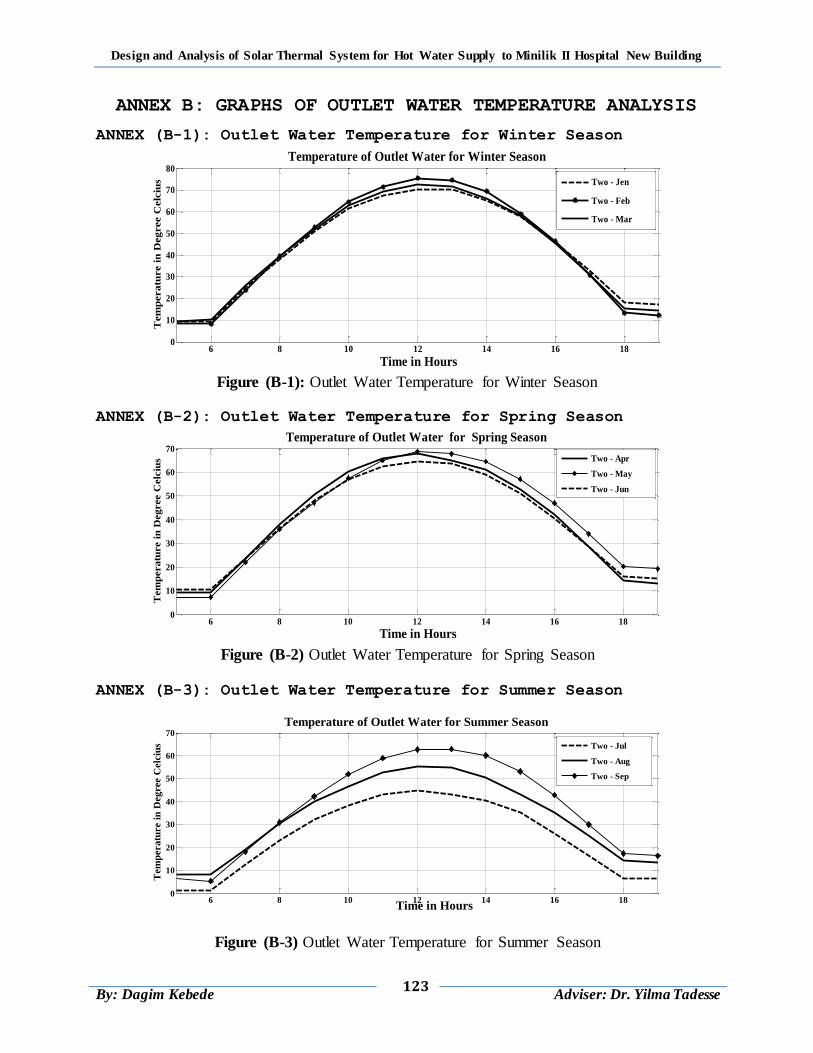
Design and Analysis of Solar Thermal System for Hot Water Supply to Minilik II Hospital New Building
123
By: Dagim Kebede
Adviser: Dr. Yilma Tadesse
ANNEX B: GRAPHS OF OUTLET WATER TEMPERATURE ANALYSIS
ANNEX (B-1): Outlet Water Temperature for Winter Season
Figure (B-1): Outlet Water Temperature for Winter Season
ANNEX (B-2): Outlet Water Temperature for Spring Season
Figure (B-2) Outlet Water Temperature for Spring Season
ANNEX (B-3): Outlet Water Temperature for Summer Season
Figure (B-3) Outlet Water Temperature for Summer Season
6 8 10 12 14 16 180
10
20
30
40
50
60
70
80
Time in Hours
Tem
pera
ture i
n D
eg
ree C
elc
ius
Temperature of Outlet Water for Winter Season
Two - Jen
Two - Feb
Two - Mar
6 8 10 12 14 16 180
10
20
30
40
50
60
70
Time in Hours
Tem
peratu
re i
n D
egree C
elc
ius
Temperature of Outlet Water for Spring Season
Two - Apr
Two - May
Two - Jun
6 8 10 12 14 16 180
10
20
30
40
50
60
70
Time in Hours
Tem
peratu
re i
n D
egree C
elc
ius
Temperature of Outlet Water for Summer Season
Two - Jul
Two - Aug
Two - Sep
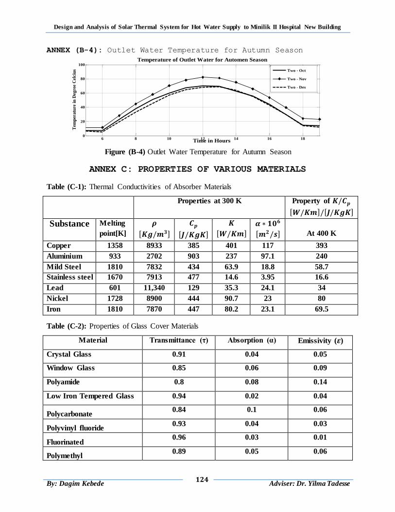
Design and Analysis of Solar Thermal System for Hot Water Supply to Minilik II Hospital New Building
124
By: Dagim Kebede
Adviser: Dr. Yilma Tadesse
ANNEX (B-4): Outlet Water Temperature for Autumn Season
Figure (B-4) Outlet Water Temperature for Autumn Season
ANNEX C: PROPERTIES OF VARIOUS MATERIALS
Table (C-1): Thermal Conductivities of Absorber Materials
Properties at 300 K Property of
Substance Melting
point[K]
At 400 K
Copper 1358 8933 385 401 117 393
Aluminium 933 2702 903 237 97.1 240
Mild Steel 1810 7832 434 63.9 18.8 58.7
Stainless steel 1670 7913 477 14.6 3.95 16.6
Lead 601 11,340 129 35.3 24.1 34
Nickel 1728 8900 444 90.7 23 80
Iron 1810 7870 447 80.2 23.1 69.5
Table (C-2): Properties of Glass Cover Materials
Material Transmittance (τ) Absorption (α) Emissivity ( )
Crystal Glass 0.91 0.04 0.05
Window Glass 0.85 0.06 0.09
Polyamide 0.8 0.08 0.14
Low Iron Tempered Glass 0.94 0.02 0.04
Polycarbonate 0.84 0.1 0.06
Polyvinyl fluoride 0.93 0.04 0.03
Fluorinated 0.96 0.03 0.01
Polymethyl 0.89 0.05 0.06
6 8 10 12 14 16 180
20
40
60
80
100
Time in Hours
Tem
per
atu
re i
n D
egre
e C
elci
us
Temperature of Outlet Water for Automen Season
Two - Oct
Two - Nov
Two - Des
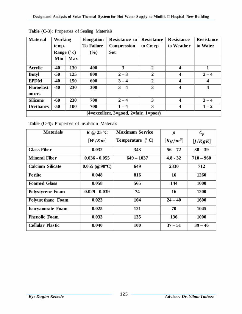
Design and Analysis of Solar Thermal System for Hot Water Supply to Minilik II Hospital New Building
125
By: Dagim Kebede
Adviser: Dr. Yilma Tadesse
Table (C-3): Properties of Sealing Materials
Material Working
temp.
Range (º c)
Elongation
To Failure
(%)
Resistance to
Compression
Set
Resistance
to Creep
Resistance
to Weather
Resistance
to Water
Min Max
Acrylic -40 130 400 3 2 4 1
Butyl -50 125 800 2 – 3 2 4 2 – 4
EPDM -40 150 600 3 – 4 2 4 4
Fluroelast
omers
-40 230 300 3 – 4 3 4 4
Silicone -60 230 700 2 – 4 3 4 3 – 4
Urethanes -50 100 700 1 – 4 3 4 1 – 2
(4=excellent, 3=good, 2=fair, 1=poor)
Table (C-4): Properties of Insulation Materials
Materials @ 25 ºC
Maximum Service
Temperature (º C)
Glass Fiber 0.032 343 56 – 72 38 – 39
Mineral Fiber 0.036 - 0.055 649 – 1037 4.8 - 32 710 – 960
Calcium Silicate 0.055 (@90ºC) 649 2330 712
Perlite 0.048 816 16 1260
Foamed Glass 0.058 565 144 1000
Polystyrene Foam 0.029 - 0.039 74 16 1200
Polyurethane Foam 0.023 104 24 – 40 1600
Isocyanurate Foam 0.025 121 70 1045
Phenolic Foam 0.033 135 136 1000
Cellular Plastic 0.040 100 37 – 51 39 – 46
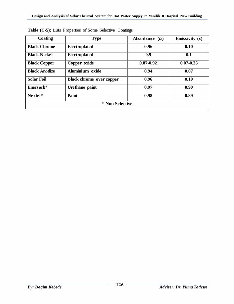
Design and Analysis of Solar Thermal System for Hot Water Supply to Minilik II Hospital New Building
126
By: Dagim Kebede
Adviser: Dr. Yilma Tadesse
Table (C-5): Lists Properties of Some Selective Coatings
Coating Type Absorbance ( ) Emissivity ( )
Black Chrome Electroplated 0.96 0.10
Black Nickel Electroplated 0.9 0.1
Black Copper Copper oxide 0.87-0.92 0.07-0.35
Black Anodize Aluminium oxide 0.94 0.07
Solar Foil Black chrome over copper 0.96 0.10
Enersorb* Urethane paint 0.97 0.90
Nextel* Paint 0.98 0.89
* Non-Selective
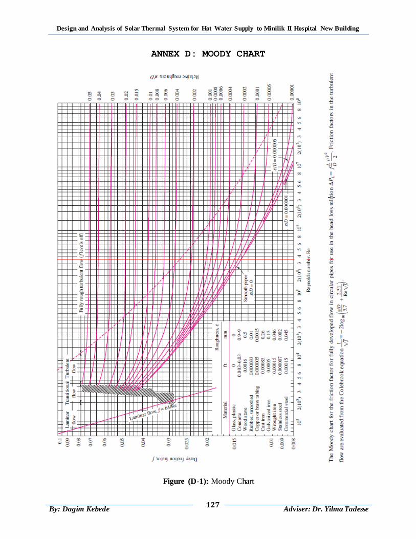
Design and Analysis of Solar Thermal System for Hot Water Supply to Minilik II Hospital New Building
127
By: Dagim Kebede
Adviser: Dr. Yilma Tadesse
ANNEX D: MOODY CHART
Figure (D-1): Moody Chart