Embed Size (px)
Citation preview
Adding Displays to iMX Developer's Kits Copyright 2016 © Embedded Artists AB
Adding Displays to
iMX Developer’s Kits

Adding Displays to iMX Developer’s Kits Page 2
Copyright 2016 © Embedded Artists AB Rev A
Embedded Artists AB Davidshallsgatan 16 SE-211 45 Malmö Sweden
http://www.EmbeddedArtists.com
Copyright 2016 © Embedded Artists AB. All rights reserved.
No part of this publication may be reproduced, transmitted, transcribed, stored in a retrieval system, or translated into any language or computer language, in any form or by any means, electronic, mechanical, magnetic, optical, chemical, manual or otherwise, without the prior written permission of Embedded Artists AB.
Disclaimer
Embedded Artists AB makes no representation or warranties with respect to the contents hereof and specifically disclaim any implied warranties or merchantability or fitness for any particular purpose. Information in this publication is subject to change without notice and does not represent a commitment on the part of Embedded Artists AB.
Feedback
We appreciate any feedback you may have for improvements on this document. Send your comments by using the contact form: www.embeddedartists.com/contact.
Trademarks
All brand and product names mentioned herein are trademarks, services marks, registered trademarks, or registered service marks of their respective owners and should be treated as such.
Adding Displays to iMX Developer’s Kits Page 3
Copyright 2016 © Embedded Artists AB Rev A
Table of Contents 1 Document Revision History ................................. 5
2 Introduction ........................................................... 6
2.1 Conventions .................................................................................... 7
3 Display Interfaces ................................................. 8
3.1 Interface Conversion .................................................................... 10
3.2 Touch Panel Interface .................................................................. 12
3.3 COM Carrier Board ....................................................................... 13
3.4 COM Display Adapter - for Parallel RGB Interface .................... 15
4 Step by Step Guide ............................................. 18
4.1 Hardware ....................................................................................... 18
4.2 Software - uBoot and Linux Configuration ................................ 19
4.3 Example of Run-time and Compile-time Configuration ............ 20
4.3.1 Run-time Configuration................................................................ 20
4.3.2 Compile-time Configuration ......................................................... 20
5 Run-time Configuration: Display ....................... 22
5.1 Background .................................................................................. 22
5.2 How does it work? ........................................................................ 22
5.3 Examples on iMX6 SoloX COM Board ........................................ 22
5.4 Examples on iMX6 UltraLite COM Board .................................... 25
5.5 Examples on iMX6 Quad COM Board ......................................... 25
5.6 Limitations .................................................................................... 25
5.7 How do I add my own display to the predefined display list? .. 26
5.8 Bootscript ..................................................................................... 26
6 Compile-time Configuration: Display ................ 28
6.1 U-boot ............................................................................................ 28
6.1.1 Disable Simplified Configuration Mode ........................................ 28
6.1.2 iMX6 UltraLite COM Board .......................................................... 29
6.1.3 iMX6 SoloX COM Board .............................................................. 29
6.1.4 iMX6 Quad COM Board............................................................... 30
6.2 Linux Kernel .................................................................................. 32
6.2.1 iMX6 UltraLite COM Board .......................................................... 32
6.2.2 iMX6 SoloX COM Board .............................................................. 32 6.2.2.1 Parallel RGB Interface ........................................................................... 33 6.2.2.2 LVDS Interface ...................................................................................... 33
6.2.3 iMX6 Quad COM Board............................................................... 34 6.2.3.1 Parallel RGB Interface ........................................................................... 34 6.2.3.2 LVDS Interface ...................................................................................... 35 6.2.3.3 HDMI Interface ...................................................................................... 36
Adding Displays to iMX Developer’s Kits Page 4
Copyright 2016 © Embedded Artists AB Rev A
7 Run-time Configuration: Touch Controller ....... 38
7.1 New Run-time Command in u-boot: eatouch ............................. 38
7.2 Background .................................................................................. 38
7.3 How does it work? ........................................................................ 38
7.4 Examples....................................................................................... 39
7.5 Limitations .................................................................................... 40
7.6 How do I add my own touch controller to the predefined list? 40
8 Compile-time Configuration: Touch Controller 41
8.1 U-boot ............................................................................................ 41
8.1.1 Disable Run-time Configuration Mode ......................................... 41
8.2 Linux Kernel .................................................................................. 41
8.2.1 Adding a New Driver ................................................................... 41
8.2.2 Using an Existing Driver .............................................................. 42
8.2.3 Use Driver from the Run-time Method ......................................... 42
Adding Displays to iMX Developer’s Kits Page 5
Copyright 2016 © Embedded Artists AB Rev A
1 Document Revision History Revision Date Description
A 2016-05-30 Initial release
Adding Displays to iMX Developer’s Kits Page 6
Copyright 2016 © Embedded Artists AB Rev A
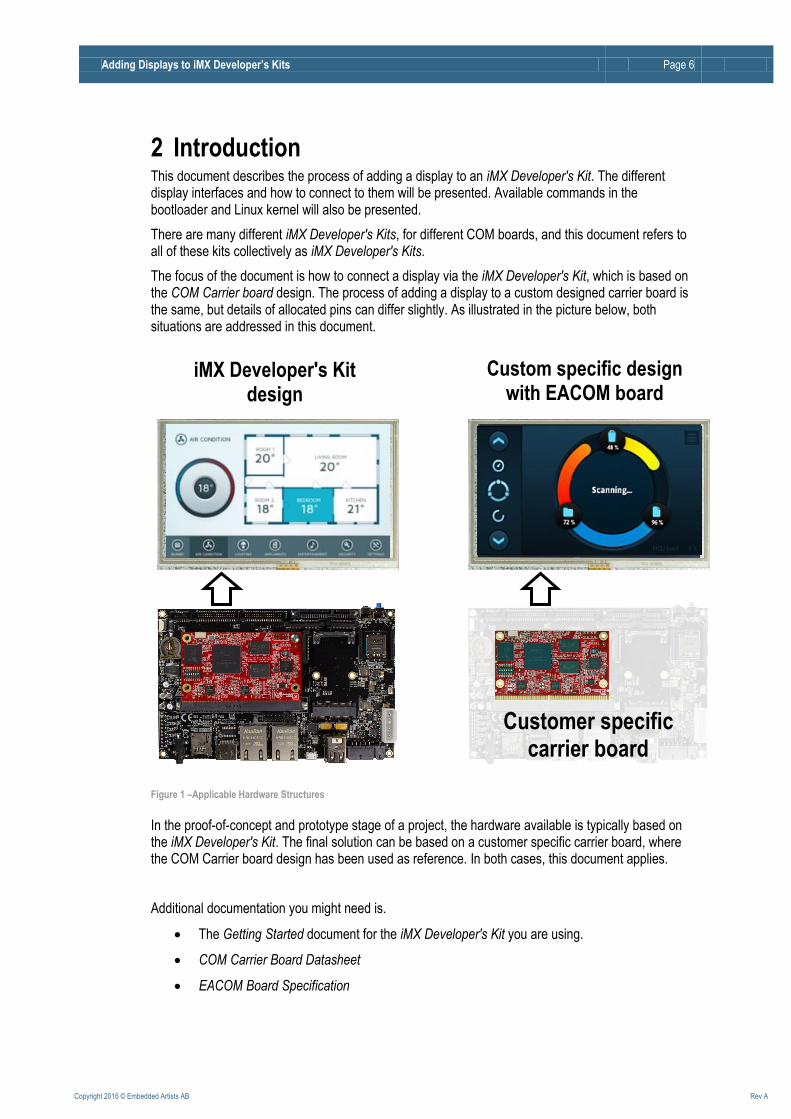
2 Introduction This document describes the process of adding a display to an iMX Developer's Kit. The different display interfaces and how to connect to them will be presented. Available commands in the bootloader and Linux kernel will also be presented.
There are many different iMX Developer's Kits, for different COM boards, and this document refers to all of these kits collectively as iMX Developer's Kits.
The focus of the document is how to connect a display via the iMX Developer's Kit, which is based on the COM Carrier board design. The process of adding a display to a custom designed carrier board is the same, but details of allocated pins can differ slightly. As illustrated in the picture below, both situations are addressed in this document.
Figure 1 –Applicable Hardware Structures
In the proof-of-concept and prototype stage of a project, the hardware available is typically based on the iMX Developer's Kit. The final solution can be based on a customer specific carrier board, where the COM Carrier board design has been used as reference. In both cases, this document applies.
Additional documentation you might need is.
The Getting Started document for the iMX Developer's Kit you are using.
COM Carrier Board Datasheet
EACOM Board Specification
iMX Developer's Kit design
Customer specific carrier board
Custom specific design with EACOM board
Adding Displays to iMX Developer’s Kits Page 7
Copyright 2016 © Embedded Artists AB Rev A
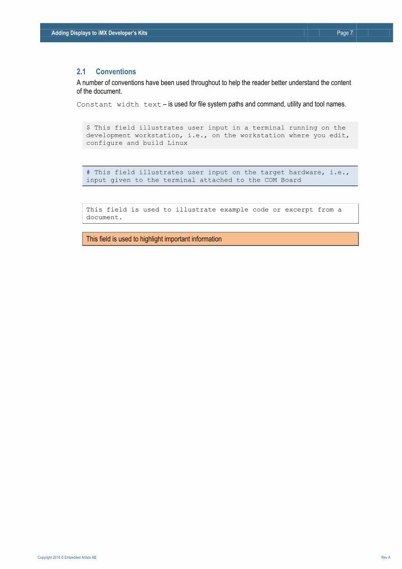
2.1 Conventions
A number of conventions have been used throughout to help the reader better understand the content of the document.
Constant width text – is used for file system paths and command, utility and tool names.
$ This field illustrates user input in a terminal running on the
development workstation, i.e., on the workstation where you edit,
configure and build Linux
# This field illustrates user input on the target hardware, i.e.,
input given to the terminal attached to the COM Board
TThhiiss ffiieelldd iiss uusseedd ttoo iilllluussttrraattee eexxaammppllee ccooddee oorr eexxcceerrpptt ffrroomm aa
ddooccuummeenntt..
This field is used to highlight important information
Adding Displays to iMX Developer’s Kits Page 8
Copyright 2016 © Embedded Artists AB Rev A
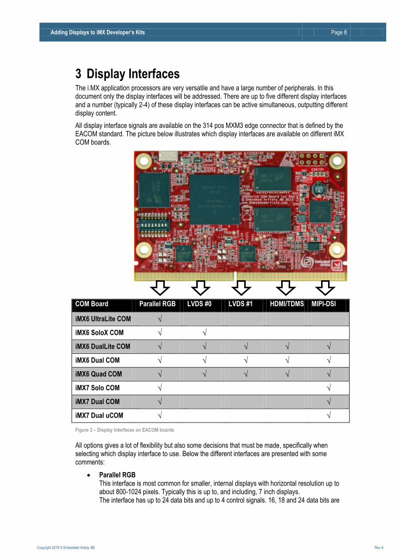
3 Display Interfaces The i.MX application processors are very versatile and have a large number of peripherals. In this document only the display interfaces will be addressed. There are up to five different display interfaces and a number (typically 2-4) of these display interfaces can be active simultaneous, outputting different display content.
All display interface signals are available on the 314 pos MXM3 edge connector that is defined by the EACOM standard. The picture below illustrates which display interfaces are available on different iMX COM boards.
COM Board Parallel RGB LVDS #0 LVDS #1 HDMI/TDMS MIPI-DSI
iMX6 UltraLite COM √
iMX6 SoloX COM √ √
iMX6 DualLite COM √ √ √ √ √
iMX6 Dual COM √ √ √ √ √
iMX6 Quad COM √ √ √ √ √
iMX7 Solo COM √ √
iMX7 Dual COM √ √
iMX7 Dual uCOM √ √
Figure 2 – Display Interfaces on EACOM boards
All options gives a lot of flexibility but also some decisions that must be made, specifically when selecting which display interface to use. Below the different interfaces are presented with some comments:
Parallel RGB This interface is most common for smaller, internal displays with horizontal resolution up to about 800-1024 pixels. Typically this is up to, and including, 7 inch displays. The interface has up to 24 data bits and up to 4 control signals. 16, 18 and 24 data bits are
Adding Displays to iMX Developer’s Kits Page 9
Copyright 2016 © Embedded Artists AB Rev A
common data (=color) widths. This results in 20-28 signals in the interface that must be routed.
LVDS (Low-Voltage Differential Signaling) This interface is common for larger, internal displays/monitors. The breakpoint is around 7-10 inch displays. Below the breakpoint, the parallel RGB interface is common. Above this the LVDS interface (or other differential signaling interface) is most common. For 18-bit color depth, one clock and three data lanes are used resulting in 8 signals (4 differential pairs) that must be routed. For 24-bit color depth one more data lane is added, resulting in 10 signals.
HDMI/DVI (TMDS - Transition-Minimized Differential Signaling) This interface is common for larger, external displays/monitors. Both HDMI and DVI-I uses the same underlying signaling technology, TMDS, which reduces electromagnetic interference over copper cables. It also enables robust clock recovery at the receiver (in other words, the receiver has high skew tolerance and long/cheap cables can be used). The interface has four differential signals and up to four control signals, resulting in up to 12 signals. An HDMI interface can also carry an audio stream (without additional signals).
MIPI-DSI (Mobile Industry Processor Interface - Display Serial Interface) This interface is common on small, high-resolution displays for handheld equipment, like mobile phones and tablets. It is a high-speed differential signaling point-to-point serial bus. It includes one high speed clock lane and one or more data lanes.
Because of radiated EMI, the parallel RGB interface should only be used over short distances, well controlled trace impedance and at lower pixel clock rates. When the pixel clock approach 30MHz (and above) the severity of the problems increase. In general, wide parallel busses can easily generate (i.e., radiate) significant interference. Note that it is not the traces that run on the pcb that is the problem. It is the FPC that interface the display that is the problem. The traces on the FPC act like antennas and lack proper ground plane (for impedance control). For longer distances (>10 cm) and higher pixel clock rates (>15MHz), considers using differential signaling instead, like LVDS, HDMI or MIPI-DSI. Differential signaling generates lower levels of EMI.
Displays with MIPI-DSI are not easy to buy. Most suppliers will only sell to customers buying very high volumes. Even if you can buy displays in low volume, the risk is very high that the display is obsolete (not available) the next time it's time to buy.
End-user products that provide an HDMI interface might be subject to HDMI royalty. Check the HDMI website for details, http://www.hdmi.org/manufacturer/terms.aspx. An alternative is to use a DVI-I connector instead. Another alternative is the DisplayPort interface.
Adding Displays to iMX Developer’s Kits Page 10
Copyright 2016 © Embedded Artists AB Rev A
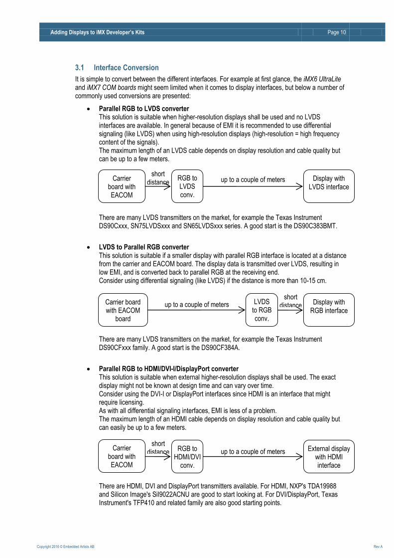
3.1 Interface Conversion
It is simple to convert between the different interfaces. For example at first glance, the iMX6 UltraLite and iMX7 COM boards might seem limited when it comes to display interfaces, but below a number of commonly used conversions are presented:
Parallel RGB to LVDS converter This solution is suitable when higher-resolution displays shall be used and no LVDS interfaces are available. In general because of EMI it is recommended to use differential signaling (like LVDS) when using high-resolution displays (high-resolution = high frequency content of the signals). The maximum length of an LVDS cable depends on display resolution and cable quality but can be up to a few meters. There are many LVDS transmitters on the market, for example the Texas Instrument DS90Cxxx, SN75LVDSxxx and SN65LVDSxxx series. A good start is the DS90C383BMT.
LVDS to Parallel RGB converter This solution is suitable if a smaller display with parallel RGB interface is located at a distance from the carrier and EACOM board. The display data is transmitted over LVDS, resulting in low EMI, and is converted back to parallel RGB at the receiving end. Consider using differential signaling (like LVDS) if the distance is more than 10-15 cm. There are many LVDS transmitters on the market, for example the Texas Instrument DS90CFxxx family. A good start is the DS90CF384A.
Parallel RGB to HDMI/DVI-I/DisplayPort converter This solution is suitable when external higher-resolution displays shall be used. The exact display might not be known at design time and can vary over time. Consider using the DVI-I or DisplayPort interfaces since HDMI is an interface that might require licensing. As with all differential signaling interfaces, EMI is less of a problem. The maximum length of an HDMI cable depends on display resolution and cable quality but can easily be up to a few meters. There are HDMI, DVI and DisplayPort transmitters available. For HDMI, NXP's TDA19988 and Silicon Image's SiI9022ACNU are good to start looking at. For DVI/DisplayPort, Texas Instrument's TFP410 and related family are also good starting points.
Carrier board with EACOM
board
Display with LVDS interface
RGB to LVDS conv.
up to a couple of meters short
distance
short distance
Carrier board with EACOM
board
Display with RGB interface
LVDS to RGB conv.
up to a couple of meters
Carrier board with EACOM
board
External display with HDMI interface
RGB to HDMI/DVI
conv.
up to a couple of meters
short distance
Adding Displays to iMX Developer’s Kits Page 11
Copyright 2016 © Embedded Artists AB Rev A
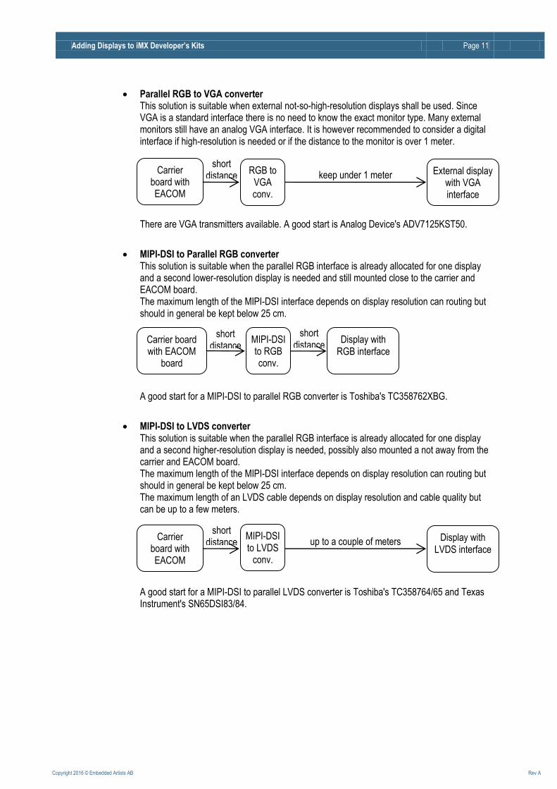
Parallel RGB to VGA converter This solution is suitable when external not-so-high-resolution displays shall be used. Since VGA is a standard interface there is no need to know the exact monitor type. Many external monitors still have an analog VGA interface. It is however recommended to consider a digital interface if high-resolution is needed or if the distance to the monitor is over 1 meter. There are VGA transmitters available. A good start is Analog Device's ADV7125KST50.
MIPI-DSI to Parallel RGB converter This solution is suitable when the parallel RGB interface is already allocated for one display and a second lower-resolution display is needed and still mounted close to the carrier and EACOM board. The maximum length of the MIPI-DSI interface depends on display resolution can routing but should in general be kept below 25 cm. A good start for a MIPI-DSI to parallel RGB converter is Toshiba's TC358762XBG.
MIPI-DSI to LVDS converter This solution is suitable when the parallel RGB interface is already allocated for one display and a second higher-resolution display is needed, possibly also mounted a not away from the carrier and EACOM board. The maximum length of the MIPI-DSI interface depends on display resolution can routing but should in general be kept below 25 cm. The maximum length of an LVDS cable depends on display resolution and cable quality but can be up to a few meters. A good start for a MIPI-DSI to parallel LVDS converter is Toshiba's TC358764/65 and Texas Instrument's SN65DSI83/84.
Carrier board with EACOM
board
External display with VGA interface
RGB to VGA conv.
keep under 1 meter
short distance
short distance
Carrier board with EACOM
board
Display with RGB interface
MIPI-DSI to RGB conv.
short distance
Carrier board with EACOM
board
Display with LVDS interface
up to a couple of meters
short distance
MIPI-DSI to LVDS
conv.
Adding Displays to iMX Developer’s Kits Page 12
Copyright 2016 © Embedded Artists AB Rev A
3.2 Touch Panel Interface
Many graphical user interfaces (GUIs) also have a touch panel over the display. Adding a display to an i.MX system typically also means adding a touch panel interface.
There are two basic types of touch panels; resistive and capacitive. The pros and cons with these technologies and all variations of them are not covered in this document. A good starting point for more information is Wikipedia: https://en.wikipedia.org/wiki/Touchscreen
Both types need a touch panel controller. The i.MX 6UltraLite application processor actually has an on-chip resistive touch controller (as a peripheral unit), but that is an exception to the rule.
Common interfaces to these controllers are:
I2C - this is by far the most common interface for smaller touch panel controllers. The interface is somewhat slow but since it is typically handled by a driver in the background it does not matter.
SPI - for faster communication with the touch panel controller some controllers also offer this interface.
USB, typically the HID profile - this interface is common for larger, external displays.
UART - some USB interface controllers also offer a UART interface as alternative.
If the touch panel is resistive a calibration procedure must typically also be implemented in the system. This procedure has nothing to do with the hardware, except that the calibrated parameters should be stored in non-volatile memory so users of the final system do not have to recalibrate the system every time it is powered.
Capacitive touch panel controllers typically have automatic built-in calibration procedures. Check each specific touch panel (and associated controller) for details.
Adding Displays to iMX Developer’s Kits Page 13
Copyright 2016 © Embedded Artists AB Rev A
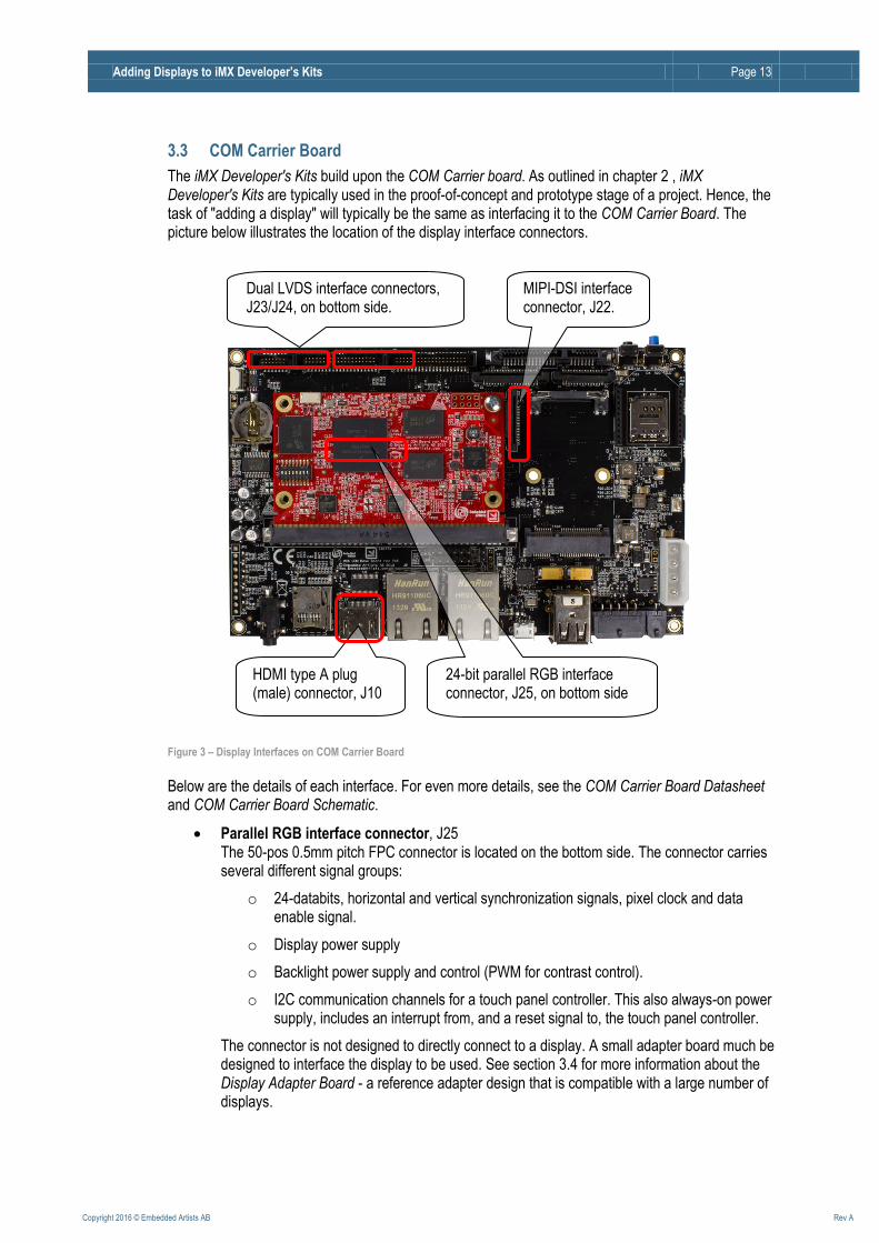
3.3 COM Carrier Board
The iMX Developer's Kits build upon the COM Carrier board. As outlined in chapter 2 , iMX Developer's Kits are typically used in the proof-of-concept and prototype stage of a project. Hence, the task of "adding a display" will typically be the same as interfacing it to the COM Carrier Board. The picture below illustrates the location of the display interface connectors.
Figure 3 – Display Interfaces on COM Carrier Board
Below are the details of each interface. For even more details, see the COM Carrier Board Datasheet and COM Carrier Board Schematic.
Parallel RGB interface connector, J25 The 50-pos 0.5mm pitch FPC connector is located on the bottom side. The connector carries several different signal groups:
o 24-databits, horizontal and vertical synchronization signals, pixel clock and data enable signal.
o Display power supply
o Backlight power supply and control (PWM for contrast control).
o I2C communication channels for a touch panel controller. This also always-on power supply, includes an interrupt from, and a reset signal to, the touch panel controller.
The connector is not designed to directly connect to a display. A small adapter board much be designed to interface the display to be used. See section 3.4 for more information about the Display Adapter Board - a reference adapter design that is compatible with a large number of displays.
Dual LVDS interface connectors, J23/J24, on bottom side.
HDMI type A plug (male) connector, J10
MIPI-DSI interface connector, J22.
24-bit parallel RGB interface connector, J25, on bottom side
Adding Displays to iMX Developer’s Kits Page 14
Copyright 2016 © Embedded Artists AB Rev A
Dual LVDS interface connectors, J23/J24 The 30 pos 1 mm pitch connectors are located on the bottom side. The connector carries several different signal groups:
o 3+1 or 4+1 data+clock signal lanes 18-bit color depth (three data lanes plus clock) is supported by default. For 24-bit color depth (requiring a fourth data lane) a smaller hardware modification must be done on the board. See COM Carrier Board Datasheet for details.
o Display Power Enable control signal
o Backlight power and control (PWM for contrast control).
o I2C communication channels for a touch panel controller. This also includes an interrupt signal from the touch panel controller.
o A second I2C communication channel for reading out possible display information (for example in EDID format). It is this I2C channel that can be traded for a fourth data lane (in 24-bit color mode).
The LVDS interface connector is designed to be compatible with NXP's/Freescale's 10.1 inch display (1024x768 pixel) that has capacitive touch. For other displays, an adapter cable is likely needed.
HDMI interface connector, J10 The 10 pos connector is called 'type A female' in the HDMI standard. The HDMI connector standard defines one clock and three data lanes for display content. It also contains an I2C channel for reading display information and hot plug detect. Optionally the one-wire, CEC bus, can be used for communication between connected HDMI devices.
MIPI-DSI interface connector, J22 The 15-pos 1mm pitch FPC connector carries 3.3V voltage and one clock and two data lanes.
Interfaces for typical touch panel controllers are available via the following connectors;
I2C via Parallel RGB interface connector, J25. This connector also contains two signals for interrupt and reset.
I2C via LVDS interface connectors, J23/J24. These connectors also contain two signals for interrupt and reset.
I2C, SPI and UART via Expansion connector, J28. This is a general expansion connector with SPI, I2C and UART interfaces.
USB via USB Host interface connector, J9. This interface is typically used for external monitors where the touch panel controller has USB interface (USB HID profile).
Note that COM Carrier Board rev A has the parallel RGB interface connector split into two connectors; J25 has 40 positions on the rev A board (instead of the 50 positions described in this document). J26 is a 10 pos FPC connector. On COM Carrier Board rev B, J26 has been merged into J25 (J26 no longer exist on this board).
Adding Displays to iMX Developer’s Kits Page 15
Copyright 2016 © Embedded Artists AB Rev A
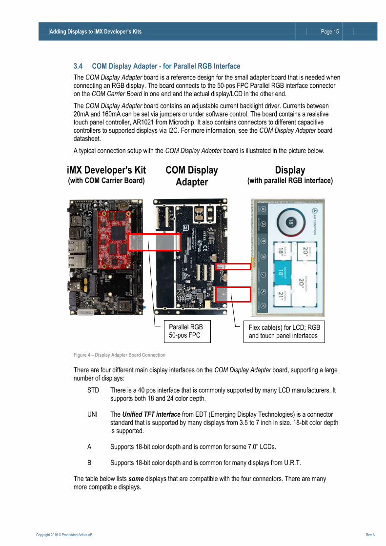
3.4 COM Display Adapter - for Parallel RGB Interface
The COM Display Adapter board is a reference design for the small adapter board that is needed when connecting an RGB display. The board connects to the 50-pos FPC Parallel RGB interface connector on the COM Carrier Board in one end and the actual display/LCD in the other end.
The COM Display Adapter board contains an adjustable current backlight driver. Currents between 20mA and 160mA can be set via jumpers or under software control. The board contains a resistive touch panel controller, AR1021 from Microchip. It also contains connectors to different capacitive controllers to supported displays via I2C. For more information, see the COM Display Adapter board datasheet.
A typical connection setup with the COM Display Adapter board is illustrated in the picture below.
Figure 4 – Display Adapter Board Connection
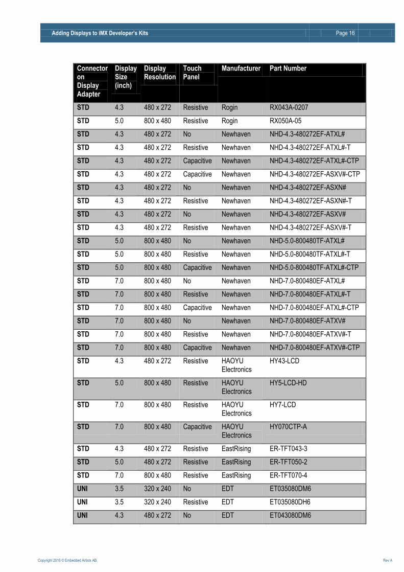
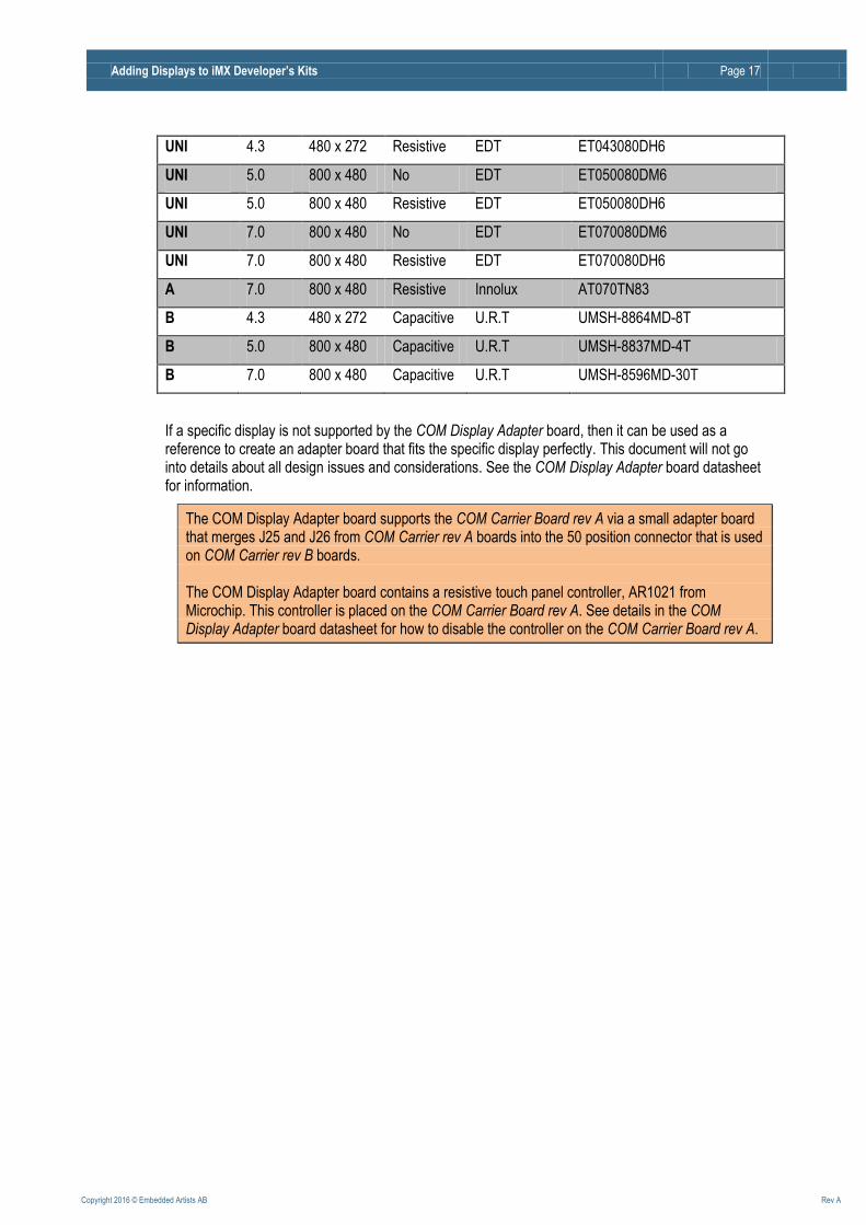
There are four different main display interfaces on the COM Display Adapter board, supporting a large number of displays:
STD There is a 40 pos interface that is commonly supported by many LCD manufacturers. It supports both 18 and 24 color depth.
UNI The Unified TFT interface from EDT (Emerging Display Technologies) is a connector standard that is supported by many displays from 3.5 to 7 inch in size. 18-bit color depth is supported.
A Supports 18-bit color depth and is common for some 7.0" LCDs.
B Supports 18-bit color depth and is common for many displays from U.R.T.
The table below lists some displays that are compatible with the four connectors. There are many more compatible displays.
iMX Developer's Kit (with COM Carrier Board)
Display (with parallel RGB interface) COM Display
Adapter
Parallel RGB 50-pos FPC
Flex cable(s) for LCD; RGB and touch panel interfaces
Adding Displays to iMX Developer’s Kits Page 16
Copyright 2016 © Embedded Artists AB Rev A
Connector on Display Adapter
Display Size (inch)
Display Resolution
Touch Panel
Manufacturer Part Number
STD 4.3 480 x 272 Resistive Rogin RX043A-0207
STD 5.0 800 x 480 Resistive Rogin RX050A-05
STD 4.3 480 x 272 No Newhaven NHD-4.3-480272EF-ATXL#
STD 4.3 480 x 272 Resistive Newhaven NHD-4.3-480272EF-ATXL#-T
STD 4.3 480 x 272 Capacitive Newhaven NHD-4.3-480272EF-ATXL#-CTP
STD 4.3 480 x 272 Capacitive Newhaven NHD-4.3-480272EF-ASXV#-CTP
STD 4.3 480 x 272 No Newhaven NHD-4.3-480272EF-ASXN#
STD 4.3 480 x 272 Resistive Newhaven NHD-4.3-480272EF-ASXN#-T
STD 4.3 480 x 272 No Newhaven NHD-4.3-480272EF-ASXV#
STD 4.3 480 x 272 Resistive Newhaven NHD-4.3-480272EF-ASXV#-T
STD 5.0 800 x 480 No Newhaven NHD-5.0-800480TF-ATXL#
STD 5.0 800 x 480 Resistive Newhaven NHD-5.0-800480TF-ATXL#-T
STD 5.0 800 x 480 Capacitive Newhaven NHD-5.0-800480TF-ATXL#-CTP
STD 7.0 800 x 480 No Newhaven NHD-7.0-800480EF-ATXL#
STD 7.0 800 x 480 Resistive Newhaven NHD-7.0-800480EF-ATXL#-T
STD 7.0 800 x 480 Capacitive Newhaven NHD-7.0-800480EF-ATXL#-CTP
STD 7.0 800 x 480 No Newhaven NHD-7.0-800480EF-ATXV#
STD 7.0 800 x 480 Resistive Newhaven NHD-7.0-800480EF-ATXV#-T
STD 7.0 800 x 480 Capacitive Newhaven NHD-7.0-800480EF-ATXV#-CTP
STD 4.3 480 x 272 Resistive HAOYU Electronics
HY43-LCD
STD 5.0 800 x 480 Resistive HAOYU Electronics
HY5-LCD-HD
STD 7.0 800 x 480 Resistive HAOYU Electronics
HY7-LCD
STD 7.0 800 x 480 Capacitive HAOYU Electronics
HY070CTP-A
STD 4.3 480 x 272 Resistive EastRising ER-TFT043-3
STD 5.0 480 x 272 Resistive EastRising ER-TFT050-2
STD 7.0 800 x 480 Resistive EastRising ER-TFT070-4
UNI 3.5 320 x 240 No EDT ET035080DM6
UNI 3.5 320 x 240 Resistive EDT ET035080DH6
UNI 4.3 480 x 272 No EDT ET043080DM6
Adding Displays to iMX Developer’s Kits Page 17
Copyright 2016 © Embedded Artists AB Rev A
UNI 4.3 480 x 272 Resistive EDT ET043080DH6
UNI 5.0 800 x 480 No EDT ET050080DM6
UNI 5.0 800 x 480 Resistive EDT ET050080DH6
UNI 7.0 800 x 480 No EDT ET070080DM6
UNI 7.0 800 x 480 Resistive EDT ET070080DH6
A 7.0 800 x 480 Resistive Innolux AT070TN83
B 4.3 480 x 272 Capacitive U.R.T UMSH-8864MD-8T
B 5.0 800 x 480 Capacitive U.R.T UMSH-8837MD-4T
B 7.0 800 x 480 Capacitive U.R.T UMSH-8596MD-30T
If a specific display is not supported by the COM Display Adapter board, then it can be used as a reference to create an adapter board that fits the specific display perfectly. This document will not go into details about all design issues and considerations. See the COM Display Adapter board datasheet for information.
The COM Display Adapter board supports the COM Carrier Board rev A via a small adapter board that merges J25 and J26 from COM Carrier rev A boards into the 50 position connector that is used on COM Carrier rev B boards. The COM Display Adapter board contains a resistive touch panel controller, AR1021 from Microchip. This controller is placed on the COM Carrier Board rev A. See details in the COM Display Adapter board datasheet for how to disable the controller on the COM Carrier Board rev A.

Adding Displays to iMX Developer’s Kits Page 18
Copyright 2016 © Embedded Artists AB Rev A
4 Step by Step Guide This chapter is a step-by-step guide how to add a display to an iMX Developer’s Kit. There are two things involved with this:
Electrically connect the display to the system. This is a hardware issue, involving:
o pin mapping of RGB signals
o pin mapping of touch panel signals and associated touch panel controller
o backlight driver with constant current control and contrast adjustment
o power management of voltages to display
Program the system to interface the display. This is a software issue, involving:
o configuring the bootloader
o configuring the OS kernel (Android, Linux, etc)
Program the system to interface the touch panel controller, if used. This is a software issue, involving:
o in some cases, configuring the bootloader, although there are no tough event in the boot loader
o configuring the OS kernel (Android, Linux, etc)
4.1 Hardware
First, the hardware side of the task is addressed:
Step 1: Does the display to be added have a parallel RGB interface? If no, continue to step 2. If yes, does the COM Display Adapter board support the display?
o If yes, prototype with the COM Display Adapter board and later use this design as base for your own, optimized adapter board.
o If no, use the COM Display Adapter board as reference for creating your own adapter board. See the COM Display Adapter board datasheet for details.
Step 2: Does the display to be added have an LVDS interface? If no, continue to step 3. If yes, create a small adapter board between the 30 pos connector on the COM Carrier Board and the display.
Step 3: Does the display to be added have HDMI/DVI-I/DisplayPort interface? If no, continue to step 4. If yes, the interface is already there. Note that the COM Carrier board has a type A plug (male) connector. If another connector is needed, for example type C (mini) or type D (micro), an adapter cable is needed.
Step 4: Does the display to be added have MIPI-DSI interface? If no, there are no more interface types available! If yes, start by asking again if this is the route to go. Unless the production volumes are very high (10K+/year) we strongly recommend you to reconsider.
Adding Displays to iMX Developer’s Kits Page 19
Copyright 2016 © Embedded Artists AB Rev A
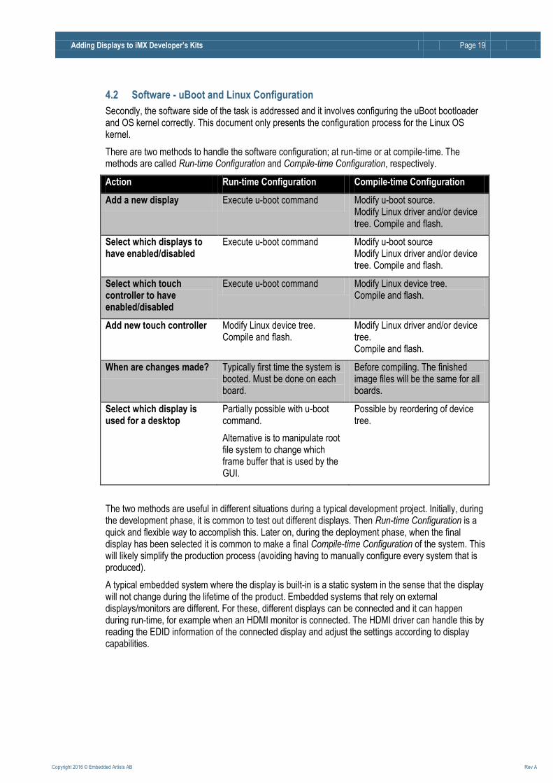
4.2 Software - uBoot and Linux Configuration
Secondly, the software side of the task is addressed and it involves configuring the uBoot bootloader and OS kernel correctly. This document only presents the configuration process for the Linux OS kernel.
There are two methods to handle the software configuration; at run-time or at compile-time. The methods are called Run-time Configuration and Compile-time Configuration, respectively.
Action Run-time Configuration Compile-time Configuration
Add a new display Execute u-boot command Modify u-boot source. Modify Linux driver and/or device tree. Compile and flash.
Select which displays to have enabled/disabled
Execute u-boot command Modify u-boot source Modify Linux driver and/or device tree. Compile and flash.
Select which touch controller to have enabled/disabled
Execute u-boot command Modify Linux device tree. Compile and flash.
Add new touch controller Modify Linux device tree. Compile and flash.
Modify Linux driver and/or device tree. Compile and flash.
When are changes made? Typically first time the system is booted. Must be done on each board.
Before compiling. The finished image files will be the same for all boards.
Select which display is used for a desktop
Partially possible with u-boot command.
Alternative is to manipulate root file system to change which frame buffer that is used by the GUI.
Possible by reordering of device tree.
The two methods are useful in different situations during a typical development project. Initially, during the development phase, it is common to test out different displays. Then Run-time Configuration is a quick and flexible way to accomplish this. Later on, during the deployment phase, when the final display has been selected it is common to make a final Compile-time Configuration of the system. This will likely simplify the production process (avoiding having to manually configure every system that is produced).
A typical embedded system where the display is built-in is a static system in the sense that the display will not change during the lifetime of the product. Embedded systems that rely on external displays/monitors are different. For these, different displays can be connected and it can happen during run-time, for example when an HDMI monitor is connected. The HDMI driver can handle this by reading the EDID information of the connected display and adjust the settings according to display capabilities.
Adding Displays to iMX Developer’s Kits Page 20
Copyright 2016 © Embedded Artists AB Rev A
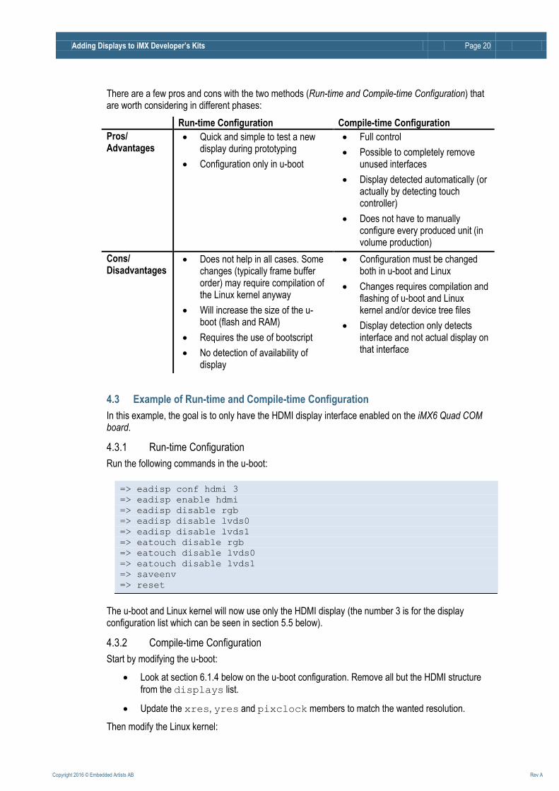
There are a few pros and cons with the two methods (Run-time and Compile-time Configuration) that are worth considering in different phases:
Run-time Configuration Compile-time Configuration
Pros/ Advantages
Quick and simple to test a new display during prototyping
Configuration only in u-boot
Full control
Possible to completely remove unused interfaces
Display detected automatically (or actually by detecting touch controller)
Does not have to manually configure every produced unit (in volume production)
Cons/ Disadvantages
Does not help in all cases. Some changes (typically frame buffer order) may require compilation of the Linux kernel anyway
Will increase the size of the u-boot (flash and RAM)
Requires the use of bootscript
No detection of availability of display
Configuration must be changed both in u-boot and Linux
Changes requires compilation and flashing of u-boot and Linux kernel and/or device tree files
Display detection only detects interface and not actual display on that interface
4.3 Example of Run-time and Compile-time Configuration
In this example, the goal is to only have the HDMI display interface enabled on the iMX6 Quad COM board.
4.3.1 Run-time Configuration
Run the following commands in the u-boot:
=> eadisp conf hdmi 3
=> eadisp enable hdmi
=> eadisp disable rgb
=> eadisp disable lvds0
=> eadisp disable lvds1
=> eatouch disable rgb
=> eatouch disable lvds0
=> eatouch disable lvds1
=> saveenv
=> reset
The u-boot and Linux kernel will now use only the HDMI display (the number 3 is for the display configuration list which can be seen in section 5.5 below).
4.3.2 Compile-time Configuration
Start by modifying the u-boot:
Look at section 6.1.4 below on the u-boot configuration. Remove all but the HDMI structure
from the displays list.
Update the xres, yres and pixclock members to match the wanted resolution.
Then modify the Linux kernel:
Adding Displays to iMX Developer’s Kits Page 21
Copyright 2016 © Embedded Artists AB Rev A
Look at section 6.2.3.3 below for HDMI configuration. Change the default resolution to the wanted default resolution.
Locate and disable the LVDS and parallel RGB interfaces by changing the status
members to disabled.
Locate and disable the touch controller configurations, for example AR1021 and eGalax.
Adding Displays to iMX Developer’s Kits Page 22
Copyright 2016 © Embedded Artists AB Rev A
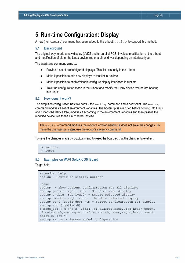
5 Run-time Configuration: Display A new (non-standard) command has been added to the u-boot, eadisp, to support this method.
5.1 Background
The original way to add a new display (LVDS and/or parallel RGB) involves modification of the u-boot and modification of either the Linux device tree or a Linux driver depending on interface type.
The eadisp command aims to:
Provide a set of preconfigured displays. This list exist only in the u-boot
Make it possible to add new displays to that list in runtime
Make it possible to enable/disable/configure display interfaces in runtime
Take the configuration made in the u-boot and modify the Linux device tree before booting into Linux.
5.2 How does it work?
The simplified configuration has two parts – the eadisp command and a bootscript. The eadisp
command modifies a set of environment variables. The bootscript is executed before booting into Linux and it loads the device tree, modifies it according to the environment variables and then passes the modified device tree to the Linux kernel instead.
The eadisp command modifies the u-boot’s environment but it does not save the changes. To
make the changes persistent use the u-boot’s saveenv command.
To save the changes made by eadisp and to reset the board so that the changes take effect:
=> saveenv
=> reset
5.3 Examples on iMX6 SoloX COM Board
To get help:
=> eadisp help
eadisp - Configure Display Support
Usage:
eadisp - Show current configuration for all displays
eadisp prefer (rgb|lvds0) - Set preferred display
eadisp enable (rgb|lvds0) - Enable selected display
eadisp disable (rgb|lvds0) - Disable selected display
eadisp conf (rgb|lvds0) num - Select configuration for display
eadisp add (rgb|lvds0)
["mode_str[:[m][j][s][18|24]:pixclkfreq,xres,yres,hback-porch,
hfront-porch,vback-porch,vfront-porch,hsync,vsync,hsact,vsact,
deact,clkact]"]
eadisp rm num - Remove added configuration
Adding Displays to iMX Developer’s Kits Page 23
Copyright 2016 © Embedded Artists AB Rev A
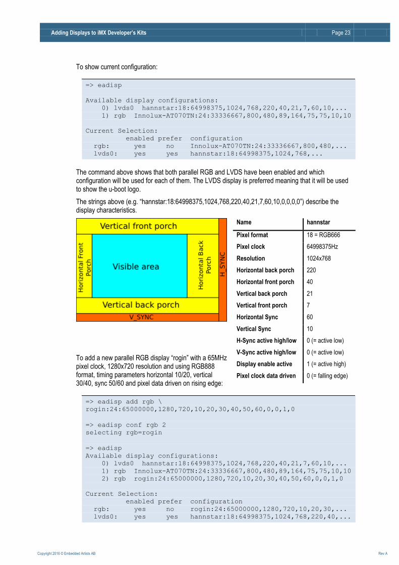
To show current configuration:
=> eadisp
Available display configurations:
0) lvds0 hannstar:18:64998375,1024,768,220,40,21,7,60,10,...
1) rgb Innolux-AT070TN:24:33336667,800,480,89,164,75,75,10,10
Current Selection:
enabled prefer configuration
rgb: yes no Innolux-AT070TN:24:33336667,800,480,...
lvds0: yes yes hannstar:18:64998375,1024,768,...
The command above shows that both parallel RGB and LVDS have been enabled and which configuration will be used for each of them. The LVDS display is preferred meaning that it will be used to show the u-boot logo.
The strings above (e.g. “hannstar:18:64998375,1024,768,220,40,21,7,60,10,0,0,0,0”) describe the display characteristics.
To add a new parallel RGB display “rogin” with a 65MHz pixel clock, 1280x720 resolution and using RGB888 format, timing parameters horizontal 10/20, vertical 30/40, sync 50/60 and pixel data driven on rising edge:
=> eadisp add rgb \
rogin:24:65000000,1280,720,10,20,30,40,50,60,0,0,1,0
=> eadisp conf rgb 2
selecting rgb=rogin
=> eadisp
Available display configurations:
0) lvds0 hannstar:18:64998375,1024,768,220,40,21,7,60,10,...
1) rgb Innolux-AT070TN:24:33336667,800,480,89,164,75,75,10,10
2) rgb rogin:24:65000000,1280,720,10,20,30,40,50,60,0,0,1,0
Current Selection:
enabled prefer configuration
rgb: yes no rogin:24:65000000,1280,720,10,20,30,...
lvds0: yes yes hannstar:18:64998375,1024,768,220,40,...
Name hannstar
Pixel format 18 = RGB666
Pixel clock 64998375Hz
Resolution 1024x768
Horizontal back porch 220
Horizontal front porch 40
Vertical back porch 21
Vertical front porch 7
Horizontal Sync 60
Vertical Sync 10
H-Sync active high/low 0 (= active low)
V-Sync active high/low 0 (= active low)
Display enable active 1 (= active high)
Pixel clock data driven 0 (= falling edge)
Adding Displays to iMX Developer’s Kits Page 24
Copyright 2016 © Embedded Artists AB Rev A
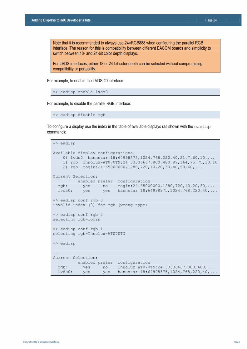
Note that it is recommended to always use 24=RGB888 when configuring the parallel RGB interface. The reason for this is compatibility between different EACOM boards and simplicity to switch between 18- and 24-bit color depth displays.
For LVDS interfaces, either 18 or 24-bit color depth can be selected without compromising compatibility or portability.
For example, to enable the LVDS #0 interface:
=> eadisp enable lvds0
For example, to disable the parallel RGB interface:
=> eadisp disable rgb
To configure a display use the index in the table of available displays (as shown with the eadisp
command):
=> eadisp
Available display configurations:
0) lvds0 hannstar:18:64998375,1024,768,220,40,21,7,60,10,...
1) rgb Innolux-AT070TN:24:33336667,800,480,89,164,75,75,10,10
2) rgb rogin:24:65000000,1280,720,10,20,30,40,50,60,...
Current Selection:
enabled prefer configuration
rgb: yes no rogin:24:65000000,1280,720,10,20,30,...
lvds0: yes yes hannstar:18:64998375,1024,768,220,40,...
=> eadisp conf rgb 0
invalid index (0) for rgb (wrong type)
=> eadisp conf rgb 2
selecting rgb=rogin
=> eadisp conf rgb 1
selecting rgb=Innolux-AT070TN
=> eadisp
...
Current Selection:
enabled prefer configuration
rgb: yes no Innolux-AT070TN:24:33336667,800,480,...
lvds0: yes yes hannstar:18:64998375,1024,768,220,40,...
Adding Displays to iMX Developer’s Kits Page 25
Copyright 2016 © Embedded Artists AB Rev A
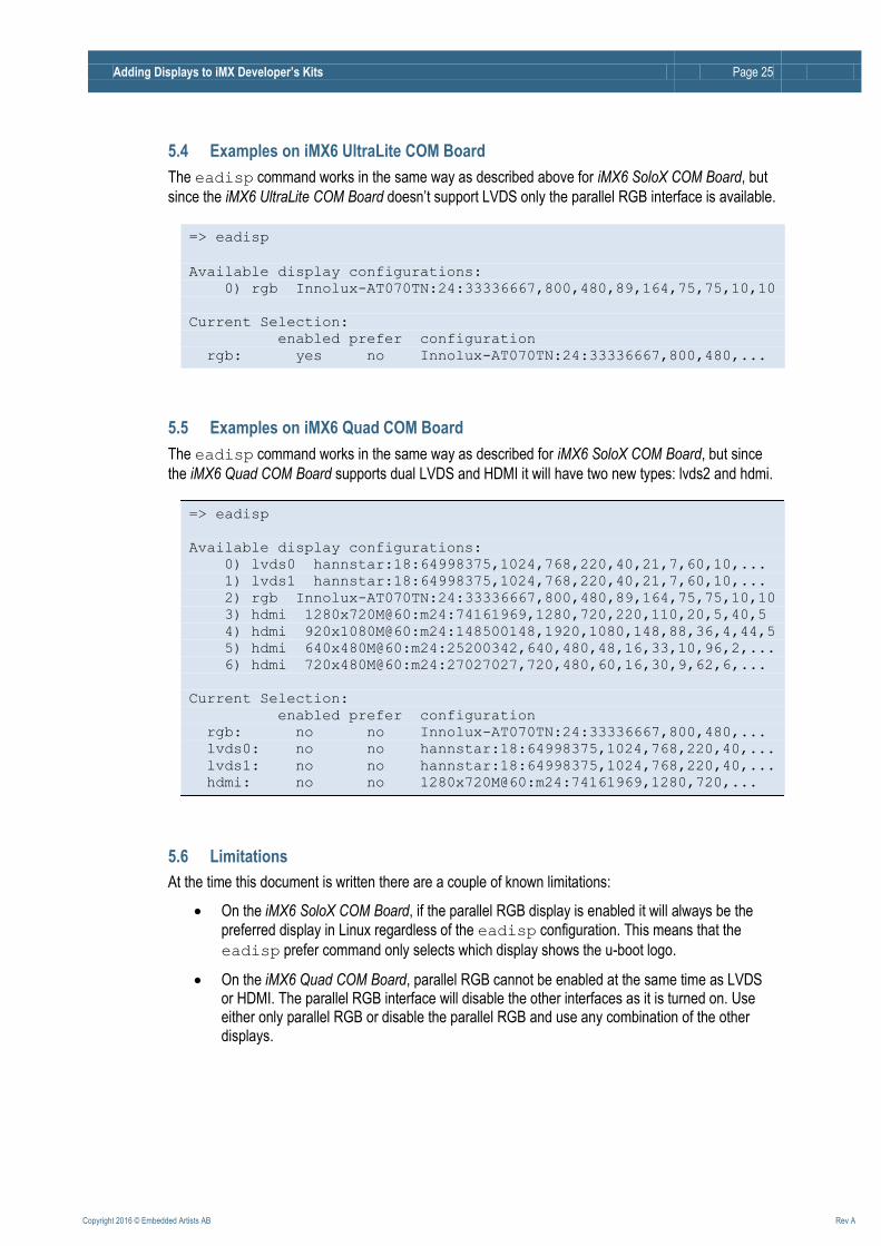
5.4 Examples on iMX6 UltraLite COM Board
The eadisp command works in the same way as described above for iMX6 SoloX COM Board, but
since the iMX6 UltraLite COM Board doesn’t support LVDS only the parallel RGB interface is available.
=> eadisp
Available display configurations:
0) rgb Innolux-AT070TN:24:33336667,800,480,89,164,75,75,10,10
Current Selection:
enabled prefer configuration
rgb: yes no Innolux-AT070TN:24:33336667,800,480,...
5.5 Examples on iMX6 Quad COM Board
The eadisp command works in the same way as described for iMX6 SoloX COM Board, but since
the iMX6 Quad COM Board supports dual LVDS and HDMI it will have two new types: lvds2 and hdmi.
=> eadisp
Available display configurations:
0) lvds0 hannstar:18:64998375,1024,768,220,40,21,7,60,10,...
1) lvds1 hannstar:18:64998375,1024,768,220,40,21,7,60,10,...
2) rgb Innolux-AT070TN:24:33336667,800,480,89,164,75,75,10,10
3) hdmi 1280x720M@60:m24:74161969,1280,720,220,110,20,5,40,5
4) hdmi 920x1080M@60:m24:148500148,1920,1080,148,88,36,4,44,5
5) hdmi 640x480M@60:m24:25200342,640,480,48,16,33,10,96,2,...
6) hdmi 720x480M@60:m24:27027027,720,480,60,16,30,9,62,6,...
Current Selection:
enabled prefer configuration
rgb: no no Innolux-AT070TN:24:33336667,800,480,...
lvds0: no no hannstar:18:64998375,1024,768,220,40,...
lvds1: no no hannstar:18:64998375,1024,768,220,40,...
hdmi: no no 1280x720M@60:m24:74161969,1280,720,...
5.6 Limitations
At the time this document is written there are a couple of known limitations:
On the iMX6 SoloX COM Board, if the parallel RGB display is enabled it will always be the
preferred display in Linux regardless of the eadisp configuration. This means that the
eadisp prefer command only selects which display shows the u-boot logo.
On the iMX6 Quad COM Board, parallel RGB cannot be enabled at the same time as LVDS or HDMI. The parallel RGB interface will disable the other interfaces as it is turned on. Use either only parallel RGB or disable the parallel RGB and use any combination of the other displays.
Adding Displays to iMX Developer’s Kits Page 26
Copyright 2016 © Embedded Artists AB Rev A
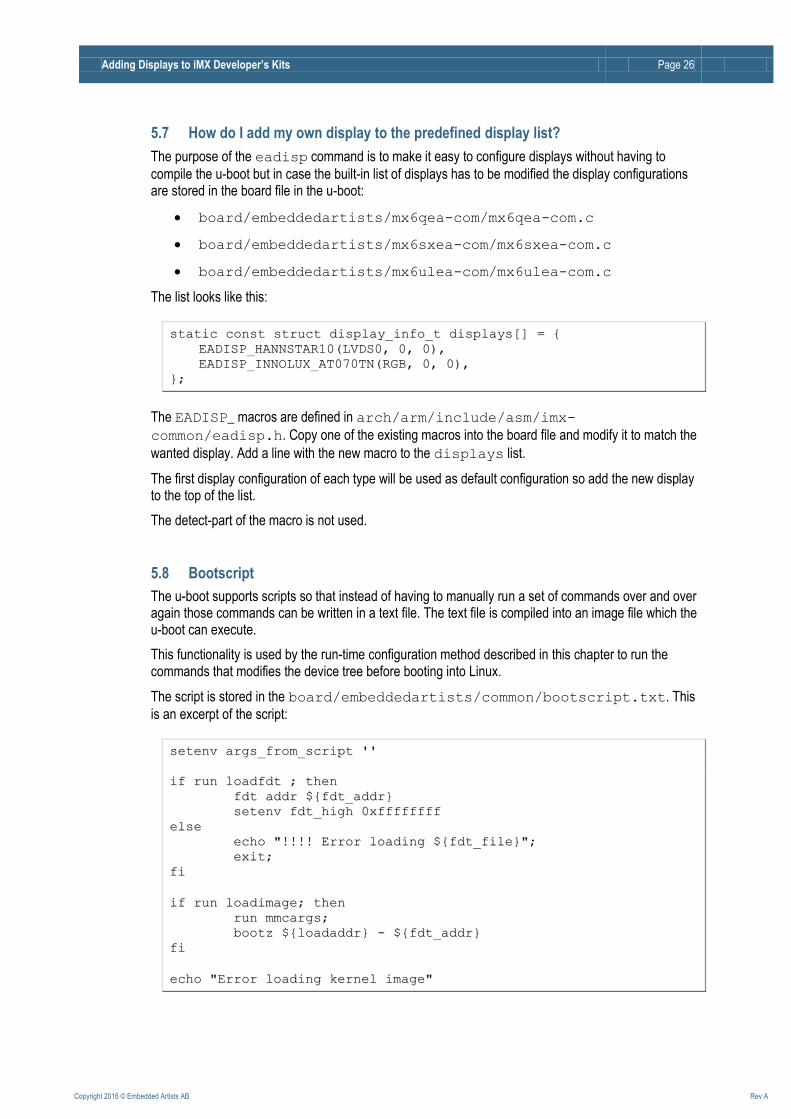
5.7 How do I add my own display to the predefined display list?
The purpose of the eadisp command is to make it easy to configure displays without having to
compile the u-boot but in case the built-in list of displays has to be modified the display configurations are stored in the board file in the u-boot:
board/embeddedartists/mx6qea-com/mx6qea-com.c
board/embeddedartists/mx6sxea-com/mx6sxea-com.c
board/embeddedartists/mx6ulea-com/mx6ulea-com.c
The list looks like this:
ssttaattiicc ccoonnsstt ssttrruucctt ddiissppllaayy__iinnffoo__tt ddiissppllaayyss[[]] == {{
EEAADDIISSPP__HHAANNNNSSTTAARR1100((LLVVDDSS00,, 00,, 00)),,
EEAADDIISSPP__IINNNNOOLLUUXX__AATT007700TTNN((RRGGBB,, 00,, 00)),,
}};;
The EADISP_ macros are defined in arch/arm/include/asm/imx-
common/eadisp.h. Copy one of the existing macros into the board file and modify it to match the
wanted display. Add a line with the new macro to the displays list.
The first display configuration of each type will be used as default configuration so add the new display to the top of the list.
The detect-part of the macro is not used.
5.8 Bootscript
The u-boot supports scripts so that instead of having to manually run a set of commands over and over again those commands can be written in a text file. The text file is compiled into an image file which the u-boot can execute.
This functionality is used by the run-time configuration method described in this chapter to run the commands that modifies the device tree before booting into Linux.
The script is stored in the board/embeddedartists/common/bootscript.txt. This
is an excerpt of the script:
sseetteennvv aarrggss__ffrroomm__ssccrriipptt ''''
iiff rruunn llooaaddffddtt ;; tthheenn
ffddtt aaddddrr $${{ffddtt__aaddddrr}}
sseetteennvv ffddtt__hhiigghh 00xxffffffffffffffff
eellssee
eecchhoo ""!!!!!!!! EErrrroorr llooaaddiinngg $${{ffddtt__ffiillee}}"";;
eexxiitt;;
ffii
iiff rruunn llooaaddiimmaaggee;; tthheenn
rruunn mmmmccaarrggss;;
bboooottzz $${{llooaaddaaddddrr}} -- $${{ffddtt__aaddddrr}}
ffii
eecchhoo ""EErrrroorr llooaaddiinngg kkeerrnneell iimmaaggee""
Adding Displays to iMX Developer’s Kits Page 27
Copyright 2016 © Embedded Artists AB Rev A
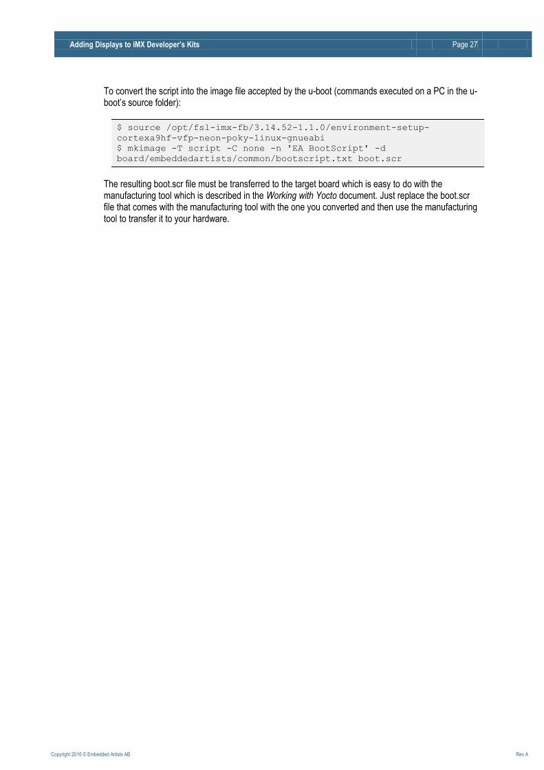
To convert the script into the image file accepted by the u-boot (commands executed on a PC in the u-boot’s source folder):
$ source /opt/fsl-imx-fb/3.14.52-1.1.0/environment-setup-
cortexa9hf-vfp-neon-poky-linux-gnueabi
$ mkimage -T script -C none -n 'EA BootScript' -d
board/embeddedartists/common/bootscript.txt boot.scr
The resulting boot.scr file must be transferred to the target board which is easy to do with the manufacturing tool which is described in the Working with Yocto document. Just replace the boot.scr file that comes with the manufacturing tool with the one you converted and then use the manufacturing tool to transfer it to your hardware.
Adding Displays to iMX Developer’s Kits Page 28
Copyright 2016 © Embedded Artists AB Rev A
6 Compile-time Configuration: Display The run-time configuration option is a good way to get started but as the project gets into the final stages and a final display setup has been selected it is recommended to have a specific configuration for the selected display. There is no need for run-time configuration in a closed end product.
The compile-time configuration steps:
1. U-boot: Disable the eadisp command that was used for the simplified configuration
2. U-boot: Add the wanted display configuration(s)
3. U-boot: Optionally remove unwanted display configuration(s)
4. Linux: Modify timing parameters for the wanted display in the device tree file
5. Linux: Optionally disable unwanted interfaces in the device tree file
6. Linux: Modify display driver (only needed for the iMX6Quad COM Board and only if the parallel RGB interface is used)
The setup varies between CPUs and has been divided into separate sections below.
The sections below only point to the origin of the display settings (driver code and/or device tree files) to give a starting point when adapting to a new display.
The u-boot and Linux kernel each have a set of display parameters. When adding a new display those parameters must be altered in both places.
6.1 U-boot
Below, <uboot> will be used as an abbreviation of the path to the root folder in which the u-boot has
been unpacked. In yocto that path will contain version numbers and other build-specific data. An example of the path:
<uboot>
/home/user/ea-bsp/build_ultra_fb_core/tmp/work/imx6ulea_com-
poky-linux-gnueabi/u-boot-imx/2015.04-r0/git
The u-boot has an environment variable panel, which can be used on CPUs that support more than
one display interface to specify which interface to use. The value of the variable should be one of the names from the displays list.
6.1.1 Disable Simplified Configuration Mode
The eadisp command can be disabled by commenting out the CONFIG_CMD_EADISP define in
the appropriate file:
<uboot>/include/configs/mx6qea-com.h
<uboot>/include/configs/mx6sxea-com.h
<uboot>/include/configs/mx6ulea-com.h
Disabling the eadisp command switches the configuration into manual mode.
Adding Displays to iMX Developer’s Kits Page 29
Copyright 2016 © Embedded Artists AB Rev A
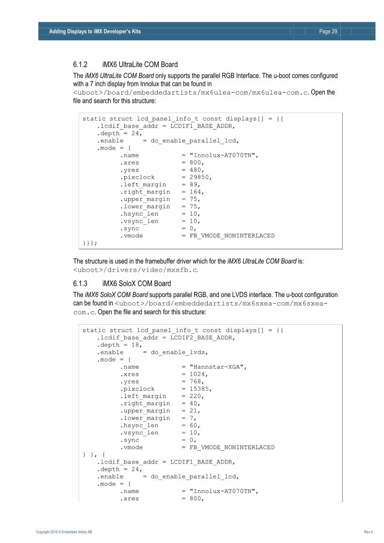
6.1.2 iMX6 UltraLite COM Board
The iMX6 UltraLite COM Board only supports the parallel RGB Interface. The u-boot comes configured with a 7 inch display from Innolux that can be found in
<uboot>/board/embeddedartists/mx6ulea-com/mx6ulea-com.c. Open the
file and search for this structure:
ssttaattiicc ssttrruucctt llccdd__ppaanneell__iinnffoo__tt ccoonnsstt ddiissppllaayyss[[]] == {{{{
..llccddiiff__bbaassee__aaddddrr == LLCCDDIIFF11__BBAASSEE__AADDDDRR,,
..ddeepptthh == 2244,,
..eennaabbllee == ddoo__eennaabbllee__ppaarraalllleell__llccdd,,
..mmooddee == {{
..nnaammee == ""IInnnnoolluuxx--AATT007700TTNN"",,
..xxrreess == 880000,,
..yyrreess == 448800,,
..ppiixxcclloocckk == 2299885500,,
..lleefftt__mmaarrggiinn == 8899,,
..rriigghhtt__mmaarrggiinn == 116644,,
..uuppppeerr__mmaarrggiinn == 7755,,
..lloowweerr__mmaarrggiinn == 7755,,
..hhssyynncc__lleenn == 1100,,
..vvssyynncc__lleenn == 1100,,
..ssyynncc == 00,,
..vvmmooddee == FFBB__VVMMOODDEE__NNOONNIINNTTEERRLLAACCEEDD
}}}}}};;
The structure is used in the framebuffer driver which for the iMX6 UltraLite COM Board is:
<uboot>/drivers/video/mxsfb.c.
6.1.3 iMX6 SoloX COM Board
The iMX6 SoloX COM Board supports parallel RGB, and one LVDS interface. The u-boot configuration
can be found in <uboot>/board/embeddedartists/mx6sxea-com/mx6sxea-
com.c. Open the file and search for this structure:
ssttaattiicc ssttrruucctt llccdd__ppaanneell__iinnffoo__tt ccoonnsstt ddiissppllaayyss[[]] == {{{{
..llccddiiff__bbaassee__aaddddrr == LLCCDDIIFF22__BBAASSEE__AADDDDRR,,
..ddeepptthh == 1188,,
..eennaabbllee == ddoo__eennaabbllee__llvvddss,,
..mmooddee == {{
..nnaammee == ""HHaannnnssttaarr--XXGGAA"",,
..xxrreess == 11002244,,
..yyrreess == 776688,,
..ppiixxcclloocckk == 1155338855,,
..lleefftt__mmaarrggiinn == 222200,,
..rriigghhtt__mmaarrggiinn == 4400,,
..uuppppeerr__mmaarrggiinn == 2211,,
..lloowweerr__mmaarrggiinn == 77,,
..hhssyynncc__lleenn == 6600,,
..vvssyynncc__lleenn == 1100,,
..ssyynncc == 00,,
..vvmmooddee == FFBB__VVMMOODDEE__NNOONNIINNTTEERRLLAACCEEDD
}} }},, {{
..llccddiiff__bbaassee__aaddddrr == LLCCDDIIFF11__BBAASSEE__AADDDDRR,,
..ddeepptthh == 2244,,
..eennaabbllee == ddoo__eennaabbllee__ppaarraalllleell__llccdd,,
..mmooddee == {{
..nnaammee == ""IInnnnoolluuxx--AATT007700TTNN"",,
..xxrreess == 880000,,

Adding Displays to iMX Developer’s Kits Page 30
Copyright 2016 © Embedded Artists AB Rev A
..yyrreess == 448800,,
..ppiixxcclloocckk == 2299885500,,
..lleefftt__mmaarrggiinn == 8899,,
..rriigghhtt__mmaarrggiinn == 116644,,
..uuppppeerr__mmaarrggiinn == 7755,,
..lloowweerr__mmaarrggiinn == 7755,,
..hhssyynncc__lleenn == 1100,,
..vvssyynncc__lleenn == 1100,,
..ssyynncc == 00,,
..vvmmooddee == FFBB__VVMMOODDEE__NNOONNIINNTTEERRLLAACCEEDD
}} }} }};;
If the panel environment variable is set to one of the names in the displays list then that is the
default display. If the variable is not set or the value is not one of the names in the list, then the first display in the list will be used as default.
The structure is used in the framebuffer driver which for the iMX6 SoloX COM Board is:
<uboot>/drivers/video/mxsfb.c.
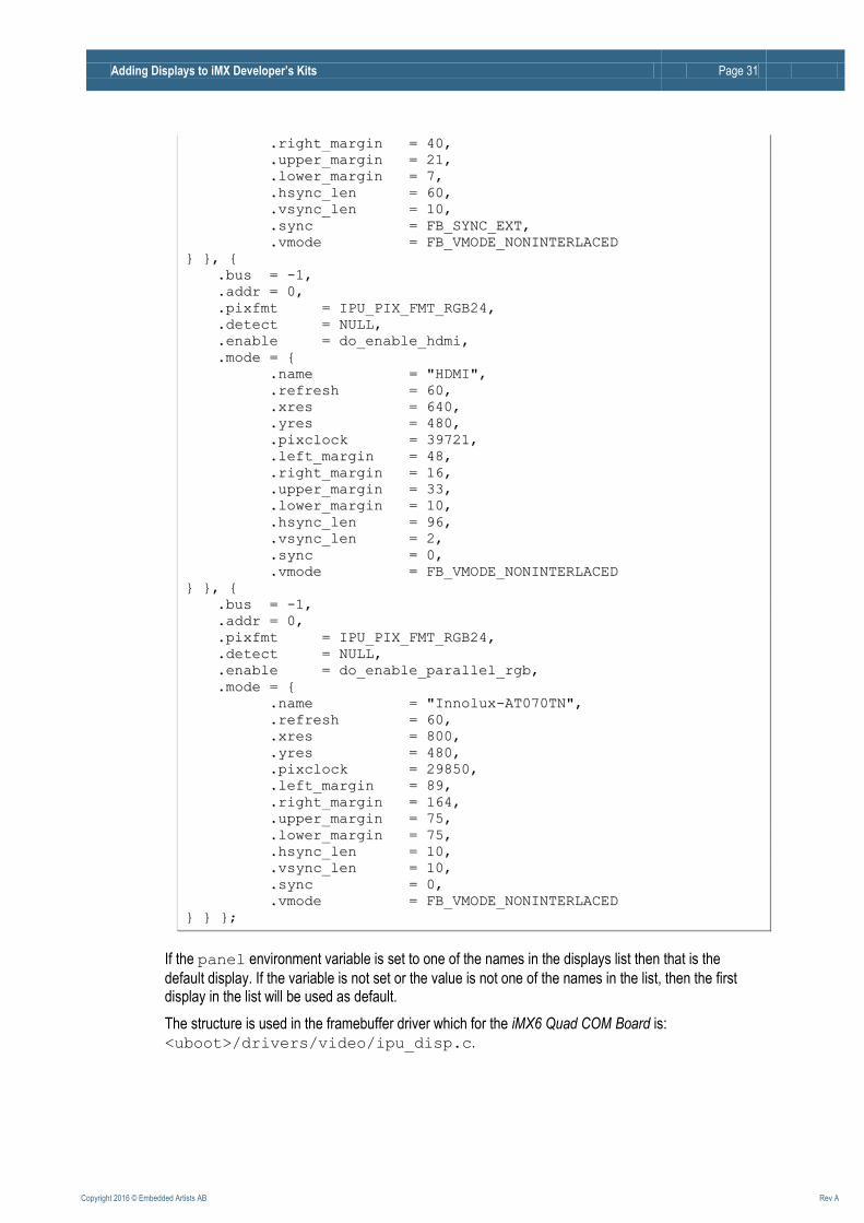
6.1.4 iMX6 Quad COM Board
The iMX6 Quad COM Board supports parallel RGB, LVDS and HDMI. The u-boot configuration can be
found in <uboot>/board/embeddedartists/mx6qea-com/mx6qea-com.c.
Open the file and search for this structure:
ssttaattiicc ssttrruucctt ddiissppllaayy__iinnffoo__tt ccoonnsstt ddiissppllaayyss[[]] == {{{{
..bbuuss == --11,,
..aaddddrr == 00,,
..ppiixxffmmtt == IIPPUU__PPIIXX__FFMMTT__RRGGBB666666,,
..ddeetteecctt == NNUULLLL,,
..eennaabbllee == ddoo__eennaabbllee__llvvddss11,,
..mmooddee == {{
..nnaammee == ""HHaannnnssttaarr--XXGGAA--LLVVDDSS11"",,
..rreeffrreesshh == 6600,,
..xxrreess == 11002244,,
..yyrreess == 776688,,
..ppiixxcclloocckk == 1155338855,,
..lleefftt__mmaarrggiinn == 222200,,
..rriigghhtt__mmaarrggiinn == 4400,,
..uuppppeerr__mmaarrggiinn == 2211,,
..lloowweerr__mmaarrggiinn == 77,,
..hhssyynncc__lleenn == 6600,,
..vvssyynncc__lleenn == 1100,,
..ssyynncc == FFBB__SSYYNNCC__EEXXTT,,
..vvmmooddee == FFBB__VVMMOODDEE__NNOONNIINNTTEERRLLAACCEEDD
}} }},, {{
..bbuuss == --11,,
..aaddddrr == 00,,
..ppiixxffmmtt == IIPPUU__PPIIXX__FFMMTT__RRGGBB666666,,
..ddeetteecctt == NNUULLLL,,
..eennaabbllee == ddoo__eennaabbllee__llvvddss00,,
..mmooddee == {{
..nnaammee == ""HHaannnnssttaarr--XXGGAA--LLVVDDSS00"",,
..rreeffrreesshh == 6600,,
..xxrreess == 11002244,,
..yyrreess == 776688,,
..ppiixxcclloocckk == 1155338855,,
..lleefftt__mmaarrggiinn == 222200,,
Adding Displays to iMX Developer’s Kits Page 31
Copyright 2016 © Embedded Artists AB Rev A
..rriigghhtt__mmaarrggiinn == 4400,,
..uuppppeerr__mmaarrggiinn == 2211,,
..lloowweerr__mmaarrggiinn == 77,,
..hhssyynncc__lleenn == 6600,,
..vvssyynncc__lleenn == 1100,,
..ssyynncc == FFBB__SSYYNNCC__EEXXTT,,
..vvmmooddee == FFBB__VVMMOODDEE__NNOONNIINNTTEERRLLAACCEEDD
}} }},, {{
..bbuuss == --11,,
..aaddddrr == 00,,
..ppiixxffmmtt == IIPPUU__PPIIXX__FFMMTT__RRGGBB2244,,
..ddeetteecctt == NNUULLLL,,
..eennaabbllee == ddoo__eennaabbllee__hhddmmii,,
..mmooddee == {{
..nnaammee == ""HHDDMMII"",,
..rreeffrreesshh == 6600,,
..xxrreess == 664400,,
..yyrreess == 448800,,
..ppiixxcclloocckk == 3399772211,,
..lleefftt__mmaarrggiinn == 4488,,
..rriigghhtt__mmaarrggiinn == 1166,,
..uuppppeerr__mmaarrggiinn == 3333,,
..lloowweerr__mmaarrggiinn == 1100,,
..hhssyynncc__lleenn == 9966,,
..vvssyynncc__lleenn == 22,,
..ssyynncc == 00,,
..vvmmooddee == FFBB__VVMMOODDEE__NNOONNIINNTTEERRLLAACCEEDD
}} }},, {{
..bbuuss == --11,,
..aaddddrr == 00,,
..ppiixxffmmtt == IIPPUU__PPIIXX__FFMMTT__RRGGBB2244,,
..ddeetteecctt == NNUULLLL,,
..eennaabbllee == ddoo__eennaabbllee__ppaarraalllleell__rrggbb,,
..mmooddee == {{
..nnaammee == ""IInnnnoolluuxx--AATT007700TTNN"",,
..rreeffrreesshh == 6600,,
..xxrreess == 880000,,
..yyrreess == 448800,,
..ppiixxcclloocckk == 2299885500,,
..lleefftt__mmaarrggiinn == 8899,,
..rriigghhtt__mmaarrggiinn == 116644,,
..uuppppeerr__mmaarrggiinn == 7755,,
..lloowweerr__mmaarrggiinn == 7755,,
..hhssyynncc__lleenn == 1100,,
..vvssyynncc__lleenn == 1100,,
..ssyynncc == 00,,
..vvmmooddee == FFBB__VVMMOODDEE__NNOONNIINNTTEERRLLAACCEEDD
}} }} }};;
If the panel environment variable is set to one of the names in the displays list then that is the
default display. If the variable is not set or the value is not one of the names in the list, then the first display in the list will be used as default.
The structure is used in the framebuffer driver which for the iMX6 Quad COM Board is:
<uboot>/drivers/video/ipu_disp.c.
Adding Displays to iMX Developer’s Kits Page 32
Copyright 2016 © Embedded Artists AB Rev A
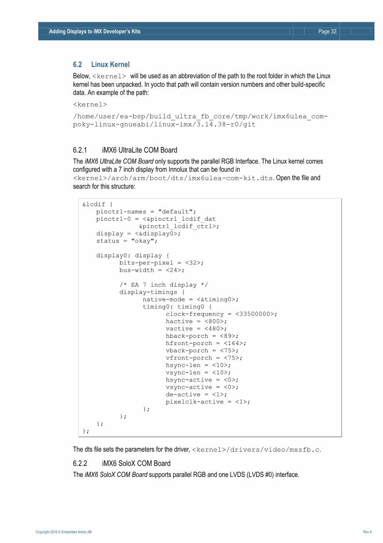
6.2 Linux Kernel
Below, <kernel> will be used as an abbreviation of the path to the root folder in which the Linux
kernel has been unpacked. In yocto that path will contain version numbers and other build-specific data. An example of the path:
<kernel>
/home/user/ea-bsp/build_ultra_fb_core/tmp/work/imx6ulea_com-
poky-linux-gnueabi/linux-imx/3.14.38-r0/git
6.2.1 iMX6 UltraLite COM Board
The iMX6 UltraLite COM Board only supports the parallel RGB Interface. The Linux kernel comes configured with a 7 inch display from Innolux that can be found in
<kernel>/arch/arm/boot/dts/imx6ulea-com-kit.dts. Open the file and
search for this structure:
&&llccddiiff {{
ppiinnccttrrll--nnaammeess == ""ddeeffaauulltt"";;
ppiinnccttrrll--00 == <<&&ppiinnccttrrll__llccddiiff__ddaatt
&&ppiinnccttrrll__llccddiiff__ccttrrll>>;;
ddiissppllaayy == <<&&ddiissppllaayy00>>;;
ssttaattuuss == ""ookkaayy"";;
ddiissppllaayy00:: ddiissppllaayy {{
bbiittss--ppeerr--ppiixxeell == <<3322>>;;
bbuuss--wwiiddtthh == <<2244>>;;
//** EEAA 77 iinncchh ddiissppllaayy **//
ddiissppllaayy--ttiimmiinnggss {{
nnaattiivvee--mmooddee == <<&&ttiimmiinngg00>>;;
ttiimmiinngg00:: ttiimmiinngg00 {{
cclloocckk--ffrreeqquueennccyy == <<3333550000000000>>;;
hhaaccttiivvee == <<880000>>;;
vvaaccttiivvee == <<448800>>;;
hhbbaacckk--ppoorrcchh == <<8899>>;;
hhffrroonntt--ppoorrcchh == <<116644>>;;
vvbbaacckk--ppoorrcchh == <<7755>>;;
vvffrroonntt--ppoorrcchh == <<7755>>;;
hhssyynncc--lleenn == <<1100>>;;
vvssyynncc--lleenn == <<1100>>;;
hhssyynncc--aaccttiivvee == <<00>>;;
vvssyynncc--aaccttiivvee == <<00>>;;
ddee--aaccttiivvee == <<11>>;;
ppiixxeellccllkk--aaccttiivvee == <<11>>;;
}};;
}};;
}};;
}};;
The dts file sets the parameters for the driver, <kernel>/drivers/video/mxsfb.c.
6.2.2 iMX6 SoloX COM Board
The iMX6 SoloX COM Board supports parallel RGB and one LVDS (LVDS #0) interface.
Adding Displays to iMX Developer’s Kits Page 33
Copyright 2016 © Embedded Artists AB Rev A
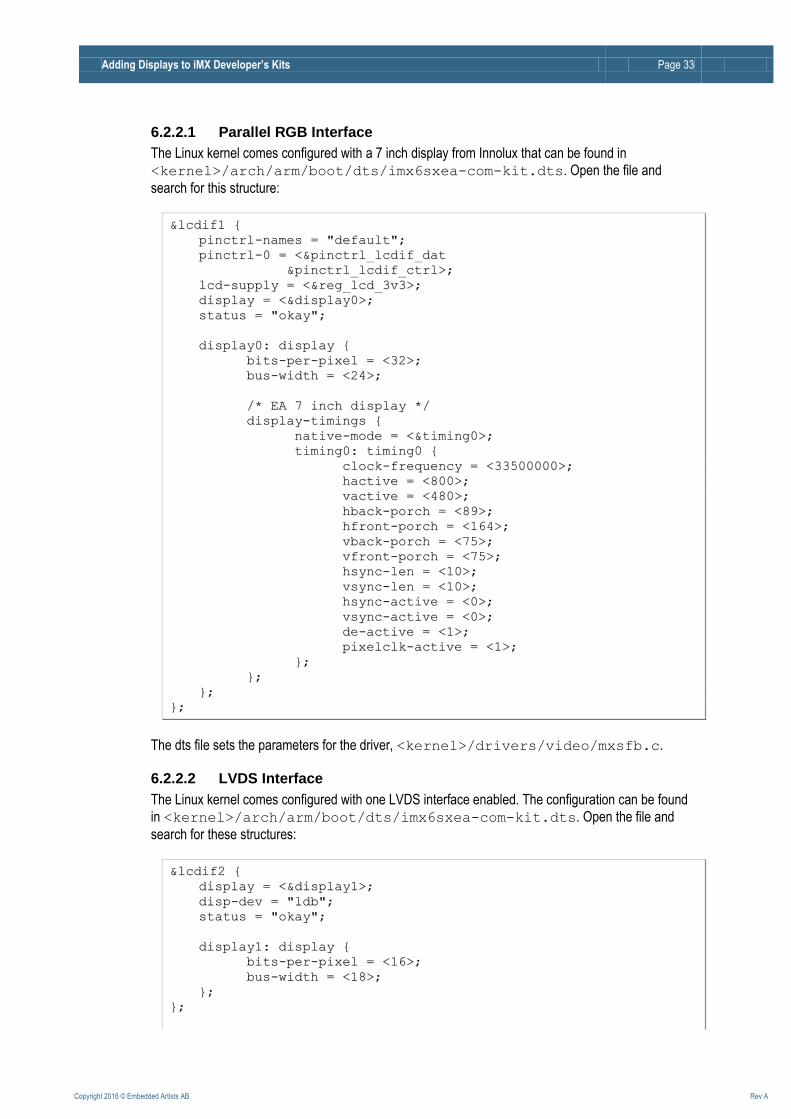
6.2.2.1 Parallel RGB Interface
The Linux kernel comes configured with a 7 inch display from Innolux that can be found in
<kernel>/arch/arm/boot/dts/imx6sxea-com-kit.dts. Open the file and
search for this structure:
&&llccddiiff11 {{
ppiinnccttrrll--nnaammeess == ""ddeeffaauulltt"";;
ppiinnccttrrll--00 == <<&&ppiinnccttrrll__llccddiiff__ddaatt
&&ppiinnccttrrll__llccddiiff__ccttrrll>>;;
llccdd--ssuuppppllyy == <<&&rreegg__llccdd__33vv33>>;;
ddiissppllaayy == <<&&ddiissppllaayy00>>;;
ssttaattuuss == ""ookkaayy"";;
ddiissppllaayy00:: ddiissppllaayy {{
bbiittss--ppeerr--ppiixxeell == <<3322>>;;
bbuuss--wwiiddtthh == <<2244>>;;
//** EEAA 77 iinncchh ddiissppllaayy **//
ddiissppllaayy--ttiimmiinnggss {{
nnaattiivvee--mmooddee == <<&&ttiimmiinngg00>>;;
ttiimmiinngg00:: ttiimmiinngg00 {{
cclloocckk--ffrreeqquueennccyy == <<3333550000000000>>;;
hhaaccttiivvee == <<880000>>;;
vvaaccttiivvee == <<448800>>;;
hhbbaacckk--ppoorrcchh == <<8899>>;;
hhffrroonntt--ppoorrcchh == <<116644>>;;
vvbbaacckk--ppoorrcchh == <<7755>>;;
vvffrroonntt--ppoorrcchh == <<7755>>;;
hhssyynncc--lleenn == <<1100>>;;
vvssyynncc--lleenn == <<1100>>;;
hhssyynncc--aaccttiivvee == <<00>>;;
vvssyynncc--aaccttiivvee == <<00>>;;
ddee--aaccttiivvee == <<11>>;;
ppiixxeellccllkk--aaccttiivvee == <<11>>;;
}};;
}};;
}};;
}};;
The dts file sets the parameters for the driver, <kernel>/drivers/video/mxsfb.c.
6.2.2.2 LVDS Interface
The Linux kernel comes configured with one LVDS interface enabled. The configuration can be found
in <kernel>/arch/arm/boot/dts/imx6sxea-com-kit.dts. Open the file and
search for these structures:
&&llccddiiff22 {{
ddiissppllaayy == <<&&ddiissppllaayy11>>;;
ddiisspp--ddeevv == ""llddbb"";;
ssttaattuuss == ""ookkaayy"";;
ddiissppllaayy11:: ddiissppllaayy {{
bbiittss--ppeerr--ppiixxeell == <<1166>>;;
bbuuss--wwiiddtthh == <<1188>>;;
}};;
}};;
Adding Displays to iMX Developer’s Kits Page 34
Copyright 2016 © Embedded Artists AB Rev A
&&llddbb {{
ssttaattuuss == ""ookkaayy"";;
llvvddss--cchhaannnneell@@00 {{
ffssll,,ddaattaa--mmaappppiinngg == ""ssppwwgg"";;
ffssll,,ddaattaa--wwiiddtthh == <<1188>>;;
ccrrttcc == ""llccddiiff22"";;
ssttaattuuss == ""ookkaayy"";;
//** HHaannnnssttaarr 1100 iinncchh **//
ddiissppllaayy--ttiimmiinnggss {{
nnaattiivvee--mmooddee == <<&&ttiimmiinngg11>>;;
ttiimmiinngg11:: hhssdd110000ppxxnn11 {{
cclloocckk--ffrreeqquueennccyy == <<6655000000000000>>;;
hhaaccttiivvee == <<11002244>>;;
vvaaccttiivvee == <<776688>>;;
hhbbaacckk--ppoorrcchh == <<222200>>;;
hhffrroonntt--ppoorrcchh == <<4400>>;;
vvbbaacckk--ppoorrcchh == <<2211>>;;
vvffrroonntt--ppoorrcchh == <<77>>;;
hhssyynncc--lleenn == <<6600>>;;
vvssyynncc--lleenn == <<1100>>;;
}};;
}};;
}};;
}};;
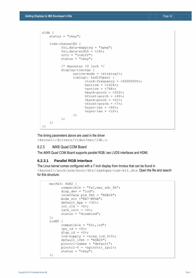
The timing parameters above are used in the driver
<kernel>/drivers/video/mxc/ldb.c.
6.2.3 iMX6 Quad COM Board
The iMX6 Quad COM Board supports parallel RGB, two LVDS interfaces and HDMI.
6.2.3.1 Parallel RGB Interface
The Linux kernel comes configured with a 7 inch display from Innolux that can be found in
<kernel>/arch/arm/boot/dts/imx6qea-com-kit.dts. Open the file and search
for this structure:
mmxxccffbb33:: ffbb@@22 {{
ccoommppaattiibbllee == ""ffssll,,mmxxcc__ssddcc__ffbb"";;
ddiisspp__ddeevv == ""llccdd"";;
iinntteerrffaaccee__ppiixx__ffmmtt == ""RRGGBB2244"";;
mmooddee__ssttrr ==""EEAA77--WWVVGGAA"";;
ddeeffaauulltt__bbpppp == <<3322>>;;
iinntt__ccllkk == <<00>>;;
llaattee__iinniitt == <<00>>;;
ssttaattuuss == ""ddiissaabblleedd"";;
}};;
llccdd@@00 {{
ccoommppaattiibbllee == ""ffssll,,llccdd"";;
iippuu__iidd == <<00>>;;
ddiisspp__iidd == <<00>>;;
llccdd--ssuuppppllyy == <<&&rreegg__llccdd__33vv33>>;;
ddeeffaauulltt__iiffmmtt == ""RRGGBB2244"";;
ppiinnccttrrll--nnaammeess == ""ddeeffaauulltt"";;
ppiinnccttrrll--00 == <<&&ppiinnccttrrll__iippuu11>>;;
ssttaattuuss == ""ookkaayy"";;
}};;
Adding Displays to iMX Developer’s Kits Page 35
Copyright 2016 © Embedded Artists AB Rev A
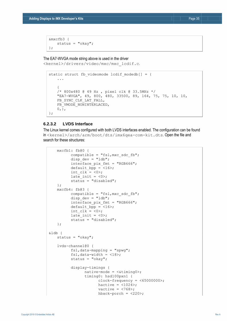
&&mmxxccffbb33 {{
ssttaattuuss == ""ookkaayy"";;
}};;
The EA7-WVGA mode string above is used in the driver
<kernel>/drivers/video/mxc/mxc_lcdif.c.
ssttaattiicc ssttrruucctt ffbb__vviiddeeoommooddee llccddiiff__mmooddeeddbb[[]] == {{
......
{{
//** 880000xx448800 @@ 4499 HHzz ,, ppiixxeell ccllkk @@ 3333..55MMHHzz **//
""EEAA77--WWVVGGAA"",, 4499,, 880000,, 448800,, 3333550000,, 8899,, 116644,, 7755,, 7755,, 1100,, 1100,,
FFBB__SSYYNNCC__CCLLKK__LLAATT__FFAALLLL,,
FFBB__VVMMOODDEE__NNOONNIINNTTEERRLLAACCEEDD,,
00,,}},,
}};;
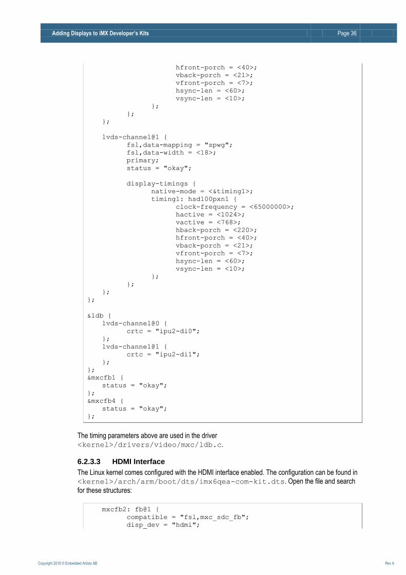
6.2.3.2 LVDS Interface
The Linux kernel comes configured with both LVDS interfaces enabled. The configuration can be found
in <kernel>/arch/arm/boot/dts/imx6qea-com-kit.dts. Open the file and
search for these structures:
mmxxccffbb11:: ffbb@@00 {{
ccoommppaattiibbllee == ""ffssll,,mmxxcc__ssddcc__ffbb"";;
ddiisspp__ddeevv == ""llddbb"";;
iinntteerrffaaccee__ppiixx__ffmmtt == ""RRGGBB666666"";;
ddeeffaauulltt__bbpppp == <<1166>>;;
iinntt__ccllkk == <<00>>;;
llaattee__iinniitt == <<00>>;;
ssttaattuuss == ""ddiissaabblleedd"";;
}};;
mmxxccffbb44:: ffbb@@33 {{
ccoommppaattiibbllee == ""ffssll,,mmxxcc__ssddcc__ffbb"";;
ddiisspp__ddeevv == ""llddbb"";;
iinntteerrffaaccee__ppiixx__ffmmtt == ""RRGGBB666666"";;
ddeeffaauulltt__bbpppp == <<1166>>;;
iinntt__ccllkk == <<00>>;;
llaattee__iinniitt == <<00>>;;
ssttaattuuss == ""ddiissaabblleedd"";;
}};;
&&llddbb {{
ssttaattuuss == ""ookkaayy"";;
llvvddss--cchhaannnneell@@00 {{
ffssll,,ddaattaa--mmaappppiinngg == ""ssppwwgg"";;
ffssll,,ddaattaa--wwiiddtthh == <<1188>>;;
ssttaattuuss == ""ookkaayy"";;
ddiissppllaayy--ttiimmiinnggss {{
nnaattiivvee--mmooddee == <<&&ttiimmiinngg00>>;;
ttiimmiinngg00:: hhssdd110000ppxxnn11 {{
cclloocckk--ffrreeqquueennccyy == <<6655000000000000>>;;
hhaaccttiivvee == <<11002244>>;;
vvaaccttiivvee == <<776688>>;;
hhbbaacckk--ppoorrcchh == <<222200>>;;
Adding Displays to iMX Developer’s Kits Page 36
Copyright 2016 © Embedded Artists AB Rev A
hhffrroonntt--ppoorrcchh == <<4400>>;;
vvbbaacckk--ppoorrcchh == <<2211>>;;
vvffrroonntt--ppoorrcchh == <<77>>;;
hhssyynncc--lleenn == <<6600>>;;
vvssyynncc--lleenn == <<1100>>;;
}};;
}};;
}};;
llvvddss--cchhaannnneell@@11 {{
ffssll,,ddaattaa--mmaappppiinngg == ""ssppwwgg"";;
ffssll,,ddaattaa--wwiiddtthh == <<1188>>;;
pprriimmaarryy;;
ssttaattuuss == ""ookkaayy"";;
ddiissppllaayy--ttiimmiinnggss {{
nnaattiivvee--mmooddee == <<&&ttiimmiinngg11>>;;
ttiimmiinngg11:: hhssdd110000ppxxnn11 {{
cclloocckk--ffrreeqquueennccyy == <<6655000000000000>>;;
hhaaccttiivvee == <<11002244>>;;
vvaaccttiivvee == <<776688>>;;
hhbbaacckk--ppoorrcchh == <<222200>>;;
hhffrroonntt--ppoorrcchh == <<4400>>;;
vvbbaacckk--ppoorrcchh == <<2211>>;;
vvffrroonntt--ppoorrcchh == <<77>>;;
hhssyynncc--lleenn == <<6600>>;;
vvssyynncc--lleenn == <<1100>>;;
}};;
}};;
}};;
}};;
&&llddbb {{
llvvddss--cchhaannnneell@@00 {{
ccrrttcc == ""iippuu22--ddii00"";;
}};;
llvvddss--cchhaannnneell@@11 {{
ccrrttcc == ""iippuu22--ddii11"";;
}};;
}};;
&&mmxxccffbb11 {{
ssttaattuuss == ""ookkaayy"";;
}};;
&&mmxxccffbb44 {{
ssttaattuuss == ""ookkaayy"";;
}};;
The timing parameters above are used in the driver
<kernel>/drivers/video/mxc/ldb.c.
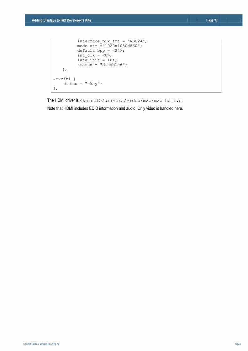
6.2.3.3 HDMI Interface
The Linux kernel comes configured with the HDMI interface enabled. The configuration can be found in
<kernel>/arch/arm/boot/dts/imx6qea-com-kit.dts. Open the file and search
for these structures:
mmxxccffbb22:: ffbb@@11 {{
ccoommppaattiibbllee == ""ffssll,,mmxxcc__ssddcc__ffbb"";;
ddiisspp__ddeevv == ""hhddmmii"";;
Adding Displays to iMX Developer’s Kits Page 37
Copyright 2016 © Embedded Artists AB Rev A
iinntteerrffaaccee__ppiixx__ffmmtt == ""RRGGBB2244"";;
mmooddee__ssttrr ==""11992200xx11008800MM@@6600"";;
ddeeffaauulltt__bbpppp == <<2244>>;;
iinntt__ccllkk == <<00>>;;
llaattee__iinniitt == <<00>>;;
ssttaattuuss == ""ddiissaabblleedd"";;
}};;
&&mmxxccffbb11 {{
ssttaattuuss == ""ookkaayy"";;
}};;
The HDMI driver is <kernel>/drivers/video/mxc/mxc_hdmi.c.
Note that HDMI includes EDID information and audio. Only video is handled here.
Adding Displays to iMX Developer’s Kits Page 38
Copyright 2016 © Embedded Artists AB Rev A
7 Run-time Configuration: Touch Controller Touch events are only available in Linux, not in the u-boot.
This chapter describes Run-time Configuration of touch panel controllers. Chapter 8 describes Compile-time Configuration.
Note that a touch panel controller is defined by: 1. I2C-bus it is connected to 2. I2C-address of the controller 3. Pins used for interrupt, reset, etc. 4. Linux driver
In Compile-time Configuration, a touch panel controller is a node under a specific I2C-bus.
In Run-time Configuration, a touch panel controller is associated with a specific display interface connector (on the COM Carrier Board - because the connector defines which I2C-bus and pins are routed to the connector).
Note that all lists of supported touch controllers represent the state at the time this document was written. Support for specific touch panel controllers can be added and deleted over time.
7.1 New Run-time Command in u-boot: eatouch
A new (non-standard) command has been added to the u-boot, eatouch, to support run-time
configuration.
7.2 Background
With the eadisp command (described in section 5 above) it is possible to add a new display, but
what if that display has a touch controller? The normal way to enable a touch controller is to make sure it is configured in the kernel, modify the device tree and then add the touch controller information to the correct i2c bus.
The eatouch command was added to make this process a bit easier. It aims to:
Provide a way to select which touch controller to use for each COM Carrier Board display interface connector.
Make it possible to enable/disable/configure touch controllers in run-time.
Take the configuration made in the u-boot and modify the Linux device tree before booting into Linux.
7.3 How does it work?
The run-time configuration has two parts – the eatouch command and a bootscript. The eatouch
command modifies a set of environment variables. The bootscript is executed before booting into Linux and it loads the device tree, modifies it according to the environment variables and then passes the modified device tree to the Linux kernel instead.
The eatouch command modifies the u-boot’s environment but it does not save the changes. To
make the changes persistent use the u-boot’s saveenv command.
To save the changes made by eatouch and to reset the board so that the changes take effect:
Adding Displays to iMX Developer’s Kits Page 39
Copyright 2016 © Embedded Artists AB Rev A
=> saveenv
=> reset
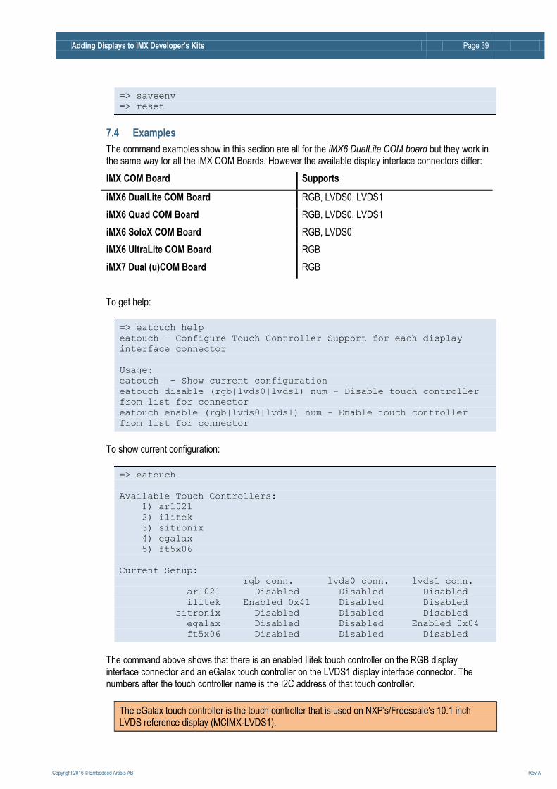
7.4 Examples
The command examples show in this section are all for the iMX6 DualLite COM board but they work in the same way for all the iMX COM Boards. However the available display interface connectors differ:
iMX COM Board Supports
iMX6 DualLite COM Board RGB, LVDS0, LVDS1
iMX6 Quad COM Board RGB, LVDS0, LVDS1
iMX6 SoloX COM Board RGB, LVDS0
iMX6 UltraLite COM Board RGB
iMX7 Dual (u)COM Board RGB
To get help:
=> eatouch help
eatouch - Configure Touch Controller Support for each display
interface connector
Usage:
eatouch - Show current configuration
eatouch disable (rgb|lvds0|lvds1) num - Disable touch controller
from list for connector
eatouch enable (rgb|lvds0|lvds1) num - Enable touch controller
from list for connector
To show current configuration:
=> eatouch
Available Touch Controllers:
1) ar1021
2) ilitek
3) sitronix
4) egalax
5) ft5x06
Current Setup:
rgb conn. lvds0 conn. lvds1 conn.
ar1021 Disabled Disabled Disabled
ilitek Enabled 0x41 Disabled Disabled
sitronix Disabled Disabled Disabled
egalax Disabled Disabled Enabled 0x04
ft5x06 Disabled Disabled Disabled
The command above shows that there is an enabled Ilitek touch controller on the RGB display interface connector and an eGalax touch controller on the LVDS1 display interface connector. The numbers after the touch controller name is the I2C address of that touch controller.
The eGalax touch controller is the touch controller that is used on NXP's/Freescale's 10.1 inch LVDS reference display (MCIMX-LVDS1).
Adding Displays to iMX Developer’s Kits Page 40
Copyright 2016 © Embedded Artists AB Rev A
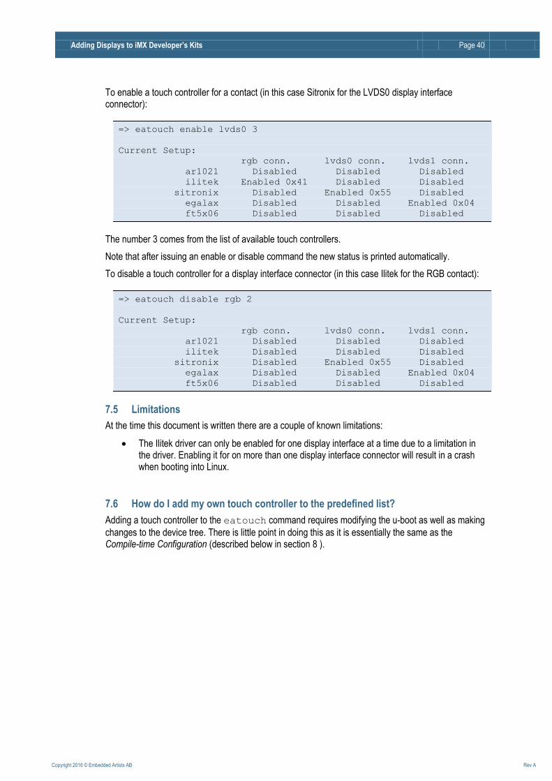
To enable a touch controller for a contact (in this case Sitronix for the LVDS0 display interface connector):
=> eatouch enable lvds0 3
Current Setup:
rgb conn. lvds0 conn. lvds1 conn.
ar1021 Disabled Disabled Disabled
ilitek Enabled 0x41 Disabled Disabled
sitronix Disabled Enabled 0x55 Disabled
egalax Disabled Disabled Enabled 0x04
ft5x06 Disabled Disabled Disabled
The number 3 comes from the list of available touch controllers.
Note that after issuing an enable or disable command the new status is printed automatically.
To disable a touch controller for a display interface connector (in this case Ilitek for the RGB contact):
=> eatouch disable rgb 2
Current Setup:
rgb conn. lvds0 conn. lvds1 conn.
ar1021 Disabled Disabled Disabled
ilitek Disabled Disabled Disabled
sitronix Disabled Enabled 0x55 Disabled
egalax Disabled Disabled Enabled 0x04
ft5x06 Disabled Disabled Disabled
7.5 Limitations
At the time this document is written there are a couple of known limitations:
The Ilitek driver can only be enabled for one display interface at a time due to a limitation in the driver. Enabling it for on more than one display interface connector will result in a crash when booting into Linux.
7.6 How do I add my own touch controller to the predefined list?
Adding a touch controller to the eatouch command requires modifying the u-boot as well as making
changes to the device tree. There is little point in doing this as it is essentially the same as the Compile-time Configuration (described below in section 8 ).
Adding Displays to iMX Developer’s Kits Page 41
Copyright 2016 © Embedded Artists AB Rev A
8 Compile-time Configuration: Touch Controller The run-time configuration option is a good way to get started but as the project gets into the final stages and a final display setup has been selected it is recommended to have a specific configuration for the selected touch controller. There is no need for run-time configuration in a closed end product.
The compile-time configuration steps:
1. U-boot: Disable the eatouch command that was used for the run-time configuration
2. Linux: Configure the wanted touch controller in the device tree file
3. Linux: Optionally disable unwanted touch controllers in the device tree file
The setup varies between CPUs and has been divided into separate sections below.
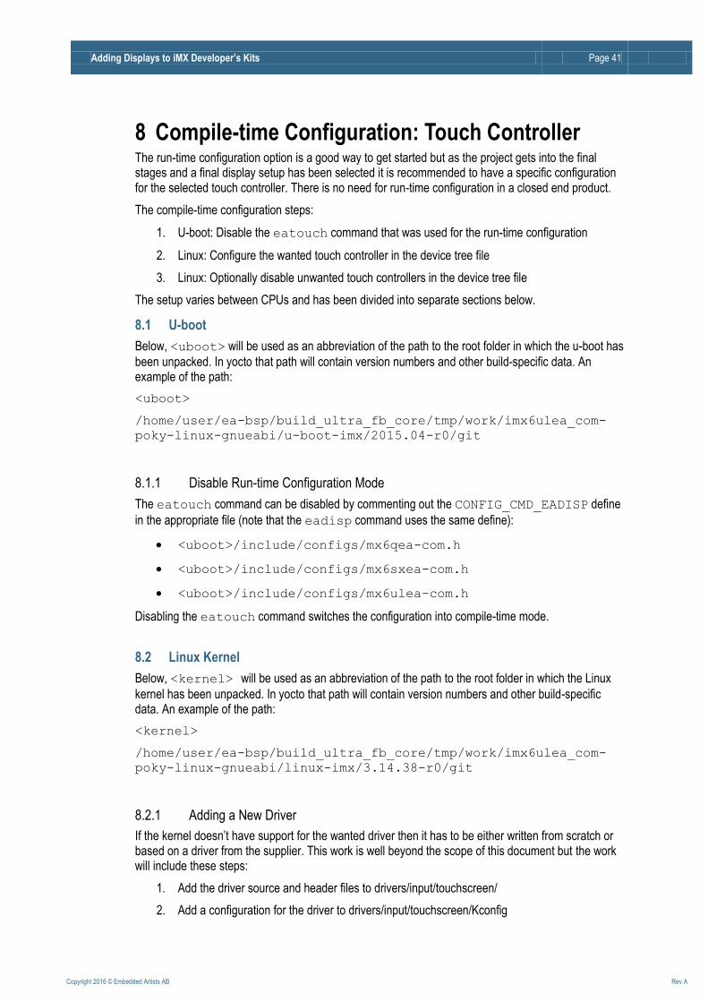
8.1 U-boot
Below, <uboot> will be used as an abbreviation of the path to the root folder in which the u-boot has
been unpacked. In yocto that path will contain version numbers and other build-specific data. An example of the path:
<uboot>
/home/user/ea-bsp/build_ultra_fb_core/tmp/work/imx6ulea_com-
poky-linux-gnueabi/u-boot-imx/2015.04-r0/git
8.1.1 Disable Run-time Configuration Mode
The eatouch command can be disabled by commenting out the CONFIG_CMD_EADISP define
in the appropriate file (note that the eadisp command uses the same define):
<uboot>/include/configs/mx6qea-com.h
<uboot>/include/configs/mx6sxea-com.h
<uboot>/include/configs/mx6ulea-com.h
Disabling the eatouch command switches the configuration into compile-time mode.
8.2 Linux Kernel
Below, <kernel> will be used as an abbreviation of the path to the root folder in which the Linux
kernel has been unpacked. In yocto that path will contain version numbers and other build-specific data. An example of the path:
<kernel>
/home/user/ea-bsp/build_ultra_fb_core/tmp/work/imx6ulea_com-
poky-linux-gnueabi/linux-imx/3.14.38-r0/git
8.2.1 Adding a New Driver
If the kernel doesn’t have support for the wanted driver then it has to be either written from scratch or based on a driver from the supplier. This work is well beyond the scope of this document but the work will include these steps:
1. Add the driver source and header files to drivers/input/touchscreen/
2. Add a configuration for the driver to drivers/input/touchscreen/Kconfig
Adding Displays to iMX Developer’s Kits Page 42
Copyright 2016 © Embedded Artists AB Rev A
3. Add the source file path to drivers/input/touchscreen/Makefile
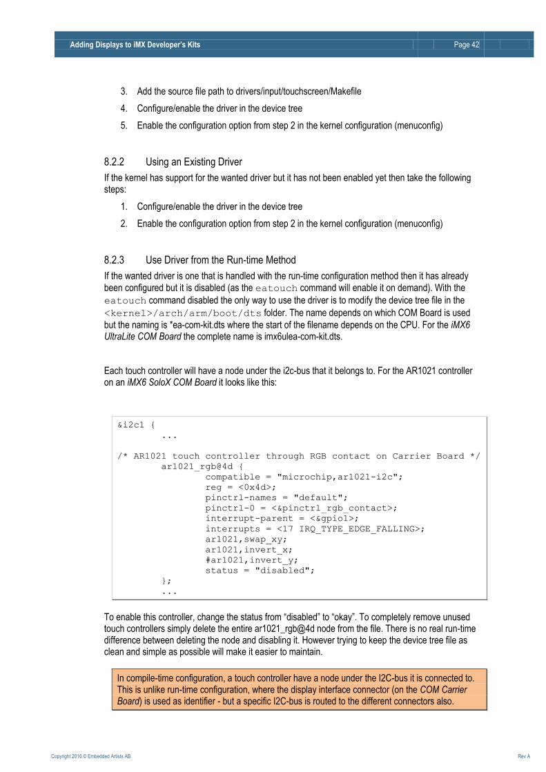
4. Configure/enable the driver in the device tree
5. Enable the configuration option from step 2 in the kernel configuration (menuconfig)
8.2.2 Using an Existing Driver
If the kernel has support for the wanted driver but it has not been enabled yet then take the following steps:
1. Configure/enable the driver in the device tree
2. Enable the configuration option from step 2 in the kernel configuration (menuconfig)
8.2.3 Use Driver from the Run-time Method
If the wanted driver is one that is handled with the run-time configuration method then it has already
been configured but it is disabled (as the eatouch command will enable it on demand). With the
eatouch command disabled the only way to use the driver is to modify the device tree file in the
<kernel>/arch/arm/boot/dts folder. The name depends on which COM Board is used
but the naming is *ea-com-kit.dts where the start of the filename depends on the CPU. For the iMX6 UltraLite COM Board the complete name is imx6ulea-com-kit.dts.
Each touch controller will have a node under the i2c-bus that it belongs to. For the AR1021 controller on an iMX6 SoloX COM Board it looks like this:
&&ii22cc11 {{
......
//** AARR11002211 ttoouucchh ccoonnttrroolllleerr tthhrroouugghh RRGGBB ccoonnttaacctt oonn CCaarrrriieerr BBooaarrdd **//
aarr11002211__rrggbb@@44dd {{
ccoommppaattiibbllee == ""mmiiccrroocchhiipp,,aarr11002211--ii22cc"";;
rreegg == <<00xx44dd>>;;
ppiinnccttrrll--nnaammeess == ""ddeeffaauulltt"";;
ppiinnccttrrll--00 == <<&&ppiinnccttrrll__rrggbb__ccoonnttaacctt>>;;
iinntteerrrruupptt--ppaarreenntt == <<&&ggppiioo11>>;;
iinntteerrrruuppttss == <<1177 IIRRQQ__TTYYPPEE__EEDDGGEE__FFAALLLLIINNGG>>;;
aarr11002211,,sswwaapp__xxyy;;
aarr11002211,,iinnvveerrtt__xx;;
##aarr11002211,,iinnvveerrtt__yy;;
ssttaattuuss == ""ddiissaabblleedd"";;
}};;
......
To enable this controller, change the status from “disabled” to “okay”. To completely remove unused touch controllers simply delete the entire ar1021_rgb@4d node from the file. There is no real run-time difference between deleting the node and disabling it. However trying to keep the device tree file as clean and simple as possible will make it easier to maintain.
In compile-time configuration, a touch controller have a node under the I2C-bus it is connected to. This is unlike run-time configuration, where the display interface connector (on the COM Carrier Board) is used as identifier - but a specific I2C-bus is routed to the different connectors also.