Embed Size (px)
Citation preview

Addendum/Corrigendum Slip No. 1 –Oct 1991 to technical Specification No. ETI/PSI/138(8/89) for Control
and Relay Board for 2 x 25 kV AT system.
S. No. Clause No. & description As amended
1. Page 6, Clause 5.5 Replace the existing clause by the following:-
“5.5 :- The sheet steel as well as other steel works shall be
properly treated and then an undercoat suitable to serve as base and binder
for the finishing coat applied. The exterior and interior surfaces and the
base frame of the panels shall be epoxy powder coated in a shade to be
mutually decided later.”
2. Page 9, Clause 9.1 3rd line Read “visual” instead of “visible.”
3. Page 22, Clazuse 20.1(v) Replace the existing matter by the following:-
“To provide a single-shot high speed auto-reclosing scheme in conjunction
with the master trip relay for reclosing the 25 kV feeder corcuit breaker
automatically in the event of its tripping on fault. The auto reclosing
scheme shall be designed for a dead time adjustable between 0.1 s and 1 s
(normally to be set at 0.5 s) and a reclaim time adjustable between 6 s and
602 s (normally to be set at 30 s, the operating duty of feeder circuit
breaker being 0 – 0.3 s – CO – 30 s - CO)”.
4. Page 23, Clause 20.6 Replace the existing matter by the following:-
“A single-shot high speed auto-reclosing scheme shall also be provided for
each feeder circuit breaker. A typical single-shot high speed auto-reclosing
scheme is at Annexure „C‟.”
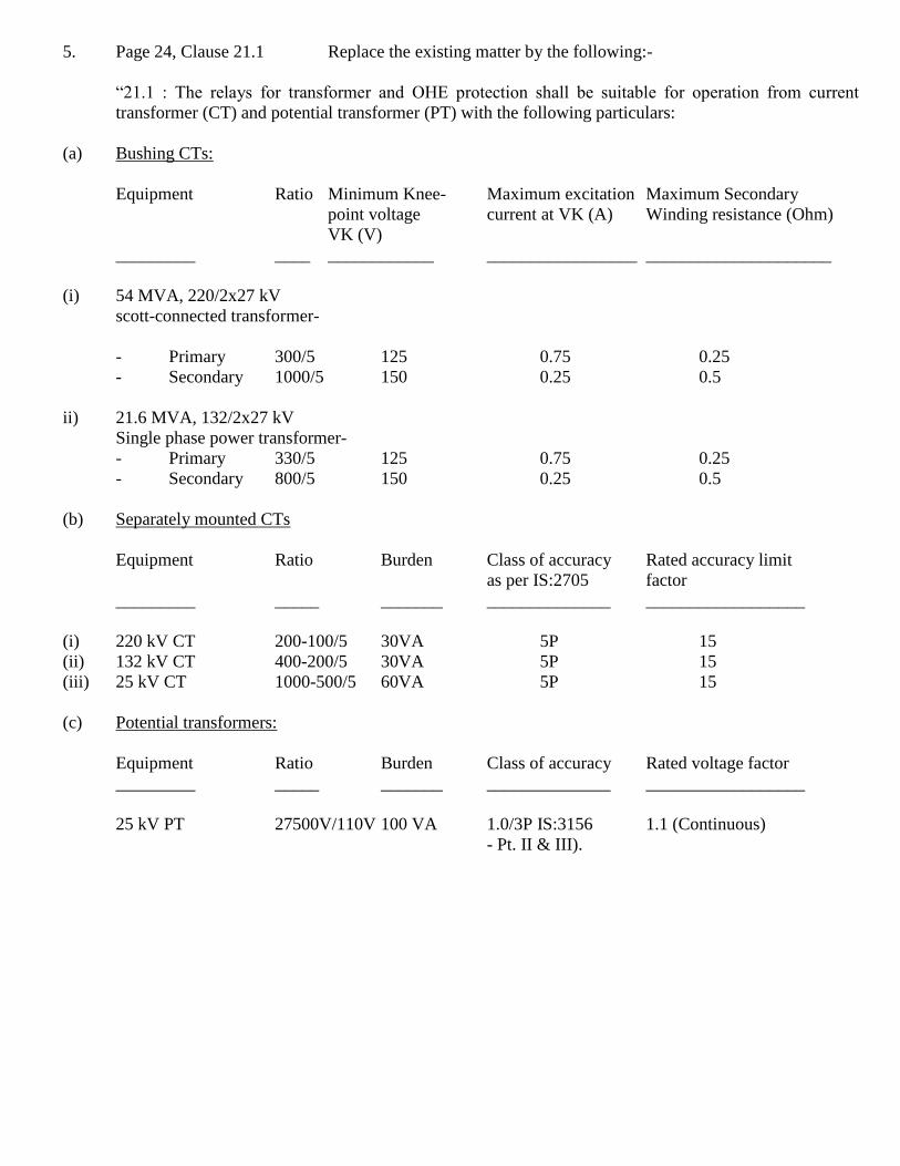
5. Page 24, Clause 21.1 Replace the existing matter by the following:-
“21.1 : The relays for transformer and OHE protection shall be suitable for operation from current
transformer (CT) and potential transformer (PT) with the following particulars:
(a) Bushing CTs:
Equipment Ratio Minimum Knee- Maximum excitation Maximum Secondary
point voltage current at VK (A) Winding resistance (Ohm)
VK (V)
_________ ____ ____________ _________________ _____________________
(i) 54 MVA, 220/2x27 kV
scott-connected transformer-
- Primary 300/5 125 0.75 0.25
- Secondary 1000/5 150 0.25 0.5
ii) 21.6 MVA, 132/2x27 kV
Single phase power transformer-
- Primary 330/5 125 0.75 0.25
- Secondary 800/5 150 0.25 0.5
(b) Separately mounted CTs
Equipment Ratio Burden Class of accuracy Rated accuracy limit
as per IS:2705 factor
_________ _____ _______ ______________ __________________
(i) 220 kV CT 200-100/5 30VA 5P 15
(ii) 132 kV CT 400-200/5 30VA 5P 15
(iii) 25 kV CT 1000-500/5 60VA 5P 15
(c) Potential transformers:
Equipment Ratio Burden Class of accuracy Rated voltage factor
_________ _____ _______ ______________ __________________
25 kV PT 27500V/110V 100 VA 1.0/3P IS:3156 1.1 (Continuous)
- Pt. II & III).
However, all details of the above transformers shall be obtained from the Purchaser/ relevant tender
papers for traction sub-stations before making the offer. Any further details/particulars regarding the
CTs and PTs that are specifically required to satisfy the application shall be clearly brought out in the
offer.
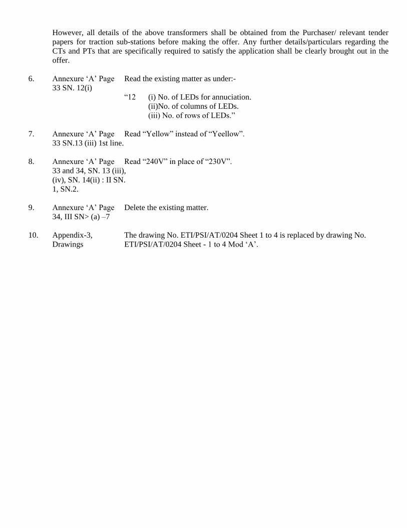
6. Annexure „A‟ Page Read the existing matter as under:-
33 SN. 12(i)
“12 (i) No. of LEDs for annuciation.
(ii)No. of columns of LEDs.
(iii) No. of rows of LEDs.”
7. Annexure „A‟ Page Read “Yellow” instead of “Yeellow”.
33 SN.13 (iii) 1st line.
8. Annexure „A‟ Page Read “240V” in place of “230V”.
33 and 34, SN. 13 (iii),
(iv), SN. 14(ii) : II SN.
1, SN.2.
9. Annexure „A‟ Page Delete the existing matter.
34, III SN> (a) –7
10. Appendix-3, The drawing No. ETI/PSI/AT/0204 Sheet 1 to 4 is replaced by drawing No.
Drawings ETI/PSI/AT/0204 Sheet - 1 to 4 Mod „A‟.
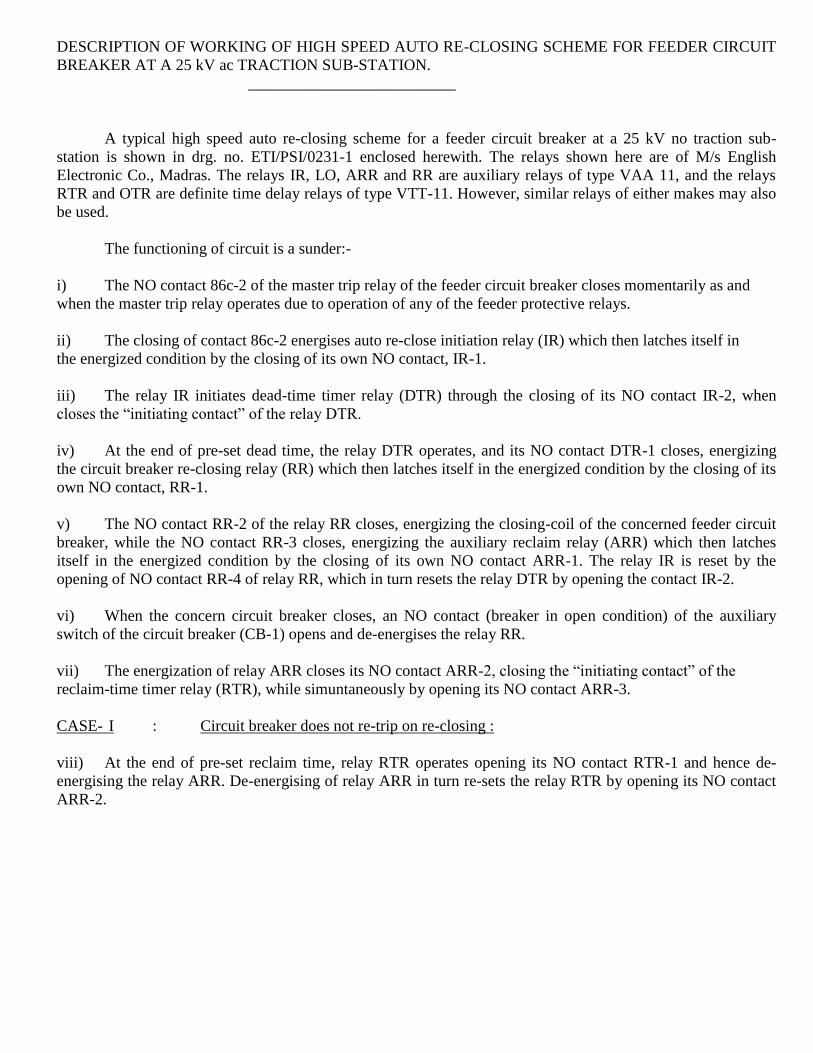
DESCRIPTION OF WORKING OF HIGH SPEED AUTO RE-CLOSING SCHEME FOR FEEDER CIRCUIT
BREAKER AT A 25 kV ac TRACTION SUB-STATION.
__________________________
A typical high speed auto re-closing scheme for a feeder circuit breaker at a 25 kV no traction sub-
station is shown in drg. no. ETI/PSI/0231-1 enclosed herewith. The relays shown here are of M/s English
Electronic Co., Madras. The relays IR, LO, ARR and RR are auxiliary relays of type VAA 11, and the relays
RTR and OTR are definite time delay relays of type VTT-11. However, similar relays of either makes may also
be used.
The functioning of circuit is a sunder:-
i) The NO contact 86c-2 of the master trip relay of the feeder circuit breaker closes momentarily as and
when the master trip relay operates due to operation of any of the feeder protective relays.
ii) The closing of contact 86c-2 energises auto re-close initiation relay (IR) which then latches itself in
the energized condition by the closing of its own NO contact, IR-1.
iii) The relay IR initiates dead-time timer relay (DTR) through the closing of its NO contact IR-2, when
closes the “initiating contact” of the relay DTR.
iv) At the end of pre-set dead time, the relay DTR operates, and its NO contact DTR-1 closes, energizing
the circuit breaker re-closing relay (RR) which then latches itself in the energized condition by the closing of its
own NO contact, RR-1.
v) The NO contact RR-2 of the relay RR closes, energizing the closing-coil of the concerned feeder circuit
breaker, while the NO contact RR-3 closes, energizing the auxiliary reclaim relay (ARR) which then latches
itself in the energized condition by the closing of its own NO contact ARR-1. The relay IR is reset by the
opening of NO contact RR-4 of relay RR, which in turn resets the relay DTR by opening the contact IR-2.
vi) When the concern circuit breaker closes, an NO contact (breaker in open condition) of the auxiliary
switch of the circuit breaker (CB-1) opens and de-energises the relay RR.
vii) The energization of relay ARR closes its NO contact ARR-2, closing the “initiating contact” of the
reclaim-time timer relay (RTR), while simuntaneously by opening its NO contact ARR-3.
CASE- I : Circuit breaker does not re-trip on re-closing :
viii) At the end of pre-set reclaim time, relay RTR operates opening its NO contact RTR-1 and hence de-
energising the relay ARR. De-energising of relay ARR in turn re-sets the relay RTR by opening its NO contact
ARR-2.
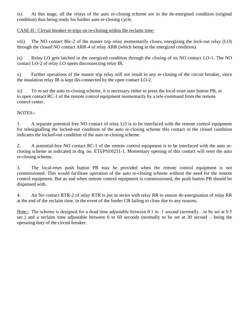
ix) At this stage, all the relays of the auto re-closing scheme are in the de-energised condition (original
condition) thus being ready for further auto re-closing cycle.
CASE-II : Circuit breaker re-trips on re-closing within the reclaim time:
viii) The NO contact 86c-2 of the master trip relay momentarily closes, energizing the lock-out relay (LO)
through the closed NO contact ARR-4 of relay ARR (which being in the energized condition).
ix) Relay LO gets latched in the energized condition through the closing of its NO contact LO-1. The NO
contact LO-2 of relay LO opens disconnecting relay IR.
x) Further operations of the master trip relay will not result in any re-closing of the circuit breaker, since
the insulation relay IR is kept dis-connected by the open contact LO-2.
xi) To re-set the auto re-closing scheme, it is necessary either to press the local-reset auto button PB, or
to open contact RC-1 of the remote control equipment momentarily by a tele-command from the remote
control center.
NOTES:-
1. A separate potential free NO contact of relay LO is to be interfaced with the remote control equipment
for telesignalling the locked-out condition of the auto re-closing scheme this contact in the closed condition
indicates the locked-out condition of the auto re-closing scheme.
2. A potential-free NO contact RC-1 of the remote control equipment is to be interfaced with the auto re-
closing scheme as indicated in drg. no. ETI/PSI/0231-1. Momentary opening of this contact will reset the auto
re-closing scheme.
3. The local-reset push button PB may be provided when the remote control equipment is not
commissioned. This would facilitate operation of the auto re-closing scheme without the need for the remote
control equipment. But as and when remote control equipment is commissioned, the push button PB should be
dispensed with.
4. An No contact RTR-2 of relay RTR is put in series with relay RR to ensure de-energisation of relay RR
at the end of the reclaim time, in the event of the feeder CB failing to close due to any reasons.
Note:- The scheme is designed for a dead time adjustable between 0.1 to 1 second (normally…to be set at 0.5
sec.) and a reclaim time adjustable between 6 to 60 seconds (normally to be set at 30 second – being the
operating duty of the circuit breaker.


Addendum/Corrigendum Slip No. 2 – Oct 1993 to Technical Specification No ETI/PSI/138(8/89) for Control
and Relay Board for 2 x 25 kV AT System.
- - - - - - - -
SN. Page No., Clause No. and As Amended
1. Page 17, Clause 18.1 Add a new clause as under:
General.
18.1.3 In the event of the tests not being carried through to completion at one stretch for any reason attributable
to the successful tenderer/manufacturer and it is required for the representative of the Purchaser/Director
General (Traction |Installation), Research Designs & Standards Organisation, Lucknow, to go again or more
number of times to the works of the successful tenderer/manufacturer or other place (s) for continuing and/or
completing the tests on the prototype (s) of the equipment, the successful tenderer/manufacturer shall reimburse
to the Purchaser/ Director General (Traction |Installation), Research Designs & Standards Organisation,
Lucknow, the cost for the representative having to visit to the works or other place (s) for the tests more than
once. The cost as claimed by the Purchaser/Director General (Traction |Installation), Research Designs &
Standards Organisation, Lucknow, shall be paid through a demand draft to the concerned accounts officer to the
Purchaser/Director General (Traction |Installation), Research Designs & Standards Organisation, Lucknow, as
shall be advised to the successful tenderer/manufacturer”.
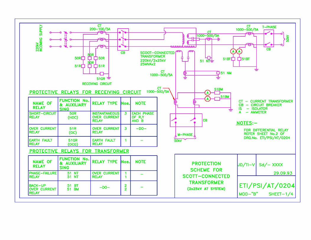
2. Page 3, SN. 10 of addendum/ Replace drawing No. ETI/PSI/AT/0204 Sheet – 1 to 4 Mod „A‟ by
corrigendum slip No. 1 – Oct drawing No. ETI/PSI/AT/0204 Sheet – 1 to 4 Mod „B‟ as enclosed.
91 – Appendix-3, Drawings.


Government of India: Ministry of Railways
Research Designs & Standard Organisation
Specification No. ETI/PSI/138 (8/89)
CONTROL & RELAY BOARD FOR 2 X 25 KV A.T.SYSTEM
1. SCOPE
1.1 This specification applies to the design, manufacture, supply and erection of control and relay boards
(hereinafter, referred as control board or simply board) for use in traction sub-stations in 2 x 25 kV AT system
for control of 220/132 kV and 25 kV circuit breakers, interrupters and protection of 220 or 132/50 kV Scott-
connected/single phase transformers as well as 25 kV over-head equipment.
1.2 The equipment offered shall be complete in all respects and shall include relays, indicating
instruments, control switches, wiring and all other accessories and materials which are necessary for efficient
operation. Such accessories and materials shall be deemed to be within the scope of this specification whether
specifically mentioned or not.
2. GENERAL
2.1 Description of 2 x 25 kV AT system:
The power for electric traction is supplied in ac 50 Hz, single phase through 2 x 25 kV AT feeding
system, which has a feeding voltage (2x25kV) from the sub-station two times as high as catenary voltage (25
kV). This high voltage power supplied form the sub-station through, catenary wire and feeder wire is steeped
down to the catenary voltage by use of autotransformers (ATs) installed about every 13 to 17 km along the
track, and then fed to the locomotives. In other words, both the catenary voltage and feeder voltage are 25 kV
against the rail, although the sub-station feeding voltage between catenary and feeder wires is 50 kV. Therefore,
the catenary voltage is the same as that of the conventional 25 kV system.
Since the power is supplied in two times higher voltage, the 2 x 25 kV At feeding system is suitable for a
large power supply, and it has the following advantages, compared with conventional feeding systems:
(a) less voltage drop in feeder circuit.
(b) large spacing of traction sub-station.
(c) less telecommunication interference.
(d) suitable for high speed operation.
The power is obtained from 220 or 132/2 x 25 kV Scott-connected/single phase transformers provided at
the sub-station. The primary windings of the transformers are connected to two or three phases of the 220 or 132
kV, three-phase, effectively earthed transmission net-work of the Electricity Board, in case of a single phase
transformer or in case of two single phase V connected transformers/ Scott-connected transformer respectively.
The Scott-connected transformer and V-connected single phase transformers are effective in reducing voltage
imbalance caused by the traction loads on the transmission net-work of the Electricity Board. The spacing
between adjacent sub-station is normally between 70 to 100 km.
One outer side terminal of the secondary windings of traction transformer is connected to the catenary,
the other outer side terminal being connected to the feeder. Two inner side terminals are, via series capacitors or
directly, connected to each other, and their joint is solidly earthed and connected to the running rails.
The load current from the sub-station flows through the catenary and returns to the sub-station through
the feeder. Between two adjacent Ats, the load current fed from the catenary to the locomotive flows in the rail
and is boosted up to the feeder through the neutral tap of the two Ats.
Midway between two sub-stations, a sectioning and paralleling post (SP) is introduced. At the points of
sub-station and sectioning post, a dead zone known as neutral section is provided in OHE to avoid a wrong
phase coupling. The power to the catenary and feeder on each side of the sub-station is fed by one feeder circuit
breaker, even if there exist two breakers for one side, and each track is controlled by an interrupter. The two
breakers are used as a stand-by for each other. For maintenance work and keeping the voltage drop within limits
one or more sub-sectioning and paralleling posts (SSPs) are introduced between traction sub-station and SP. On
a double track section, a SSP normally has four sectioning interrupters and one paralleling interrupter and a SP
has two paralleling interrupters and two bridging circuit breakers. In case of fault on the OHE, the
corresponding feeder circuit breaker of the sub-station a trips and isolates it.
A figure showing the principle of AT feeding system and a typical power supply diagram showing the
general feeding arrangement at a traction sub-station and sections of the OHE are given in the sketch at the
Appendix-I
2.2 The control and relay boards are required for use in control rooms of 220 or 132/50 kV unattended
traction sub-station.
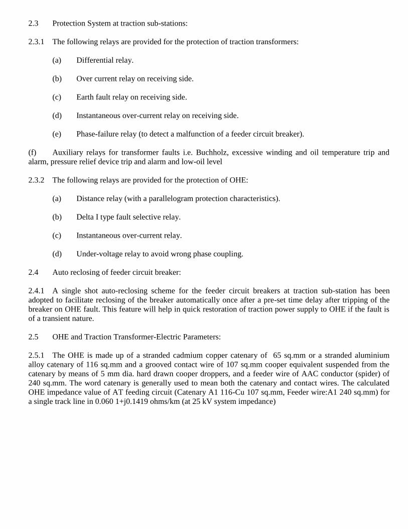
2.3 Protection System at traction sub-stations:
2.3.1 The following relays are provided for the protection of traction transformers:
(a) Differential relay.
(b) Over current relay on receiving side.
(c) Earth fault relay on receiving side.
(d) Instantaneous over-current relay on receiving side.
(e) Phase-failure relay (to detect a malfunction of a feeder circuit breaker).
(f) Auxiliary relays for transformer faults i.e. Buchholz, excessive winding and oil temperature trip and
alarm, pressure relief device trip and alarm and low-oil level
2.3.2 The following relays are provided for the protection of OHE:
(a) Distance relay (with a parallelogram protection characteristics).
(b) Delta I type fault selective relay.
(c) Instantaneous over-current relay.
(d) Under-voltage relay to avoid wrong phase coupling.
2.4 Auto reclosing of feeder circuit breaker:
2.4.1 A single shot auto-reclosing scheme for the feeder circuit breakers at traction sub-station has been
adopted to facilitate reclosing of the breaker automatically once after a pre-set time delay after tripping of the
breaker on OHE fault. This feature will help in quick restoration of traction power supply to OHE if the fault is
of a transient nature.
2.5 OHE and Traction Transformer-Electric Parameters:
2.5.1 The OHE is made up of a stranded cadmium copper catenary of 65 sq.mm or a stranded aluminium
alloy catenary of 116 sq.mm and a grooved contact wire of 107 sq.mm cooper equivalent suspended from the
catenary by means of 5 mm dia. hard drawn cooper droppers, and a feeder wire of AAC conductor (spider) of
240 sq.mm. The word catenary is generally used to mean both the catenary and contact wires. The calculated
OHE impedance value of AT feeding circuit (Catenary A1 116-Cu 107 sq.mm, Feeder wire:A1 240 sq.mm) for
a single track line in 0.060 1+j0.1419 ohms/km (at 25 kV system impedance)
2.5.2 Traction Transformer: The percentage impedance of a. 2 x 25 MVA, 220/2 x 25 kV Scott-connected
transformer and a. 20 MVA, 132/2 x 25 kV single-phase transformer are 12% (at 27 MVA base) and 12% (at
21.6 MVA base), respectively.
2.6 Nature of faults on the OHE system
2.6.1 OHE (including a feeder wire) is subjected to frequent earth faults caused by failure of insulation or
by the OHE snapping and touching rail or earth or by a piece of wire dropped by birds connecting the OHE
to earthed overlying structures, miscreant activities etc. These faults are cleared by the feeder circuit breaker
which operates on any one or both of following relays:
(a) Distance relay (with a parallelogram protection characteristics).
(b) Delta I type fault selective relay.
2.6.2 Short circuit level: The 220 kV and 132 kV source impedance may be, based on a three phase
symmetrical short circuit level, between 2000 and 10000 MVA and between 1000 to 5000 MVA, respectively.
The level of short circuit on the 25 kV side for a fault in the vicinity of a sub-station could be around 200 MVA
or more.
3. ENVIRONMENTAL CONDITIONS
3.1 The control and relay panels are intended for use in moist tropical climate with the following
atmospheric conditions.
i) Max. temperature of air in shade - 50 Deg.C
ii) Min. temperature of air in shade - 0 Deg.C
iii) Max. temperature attainable by an object - 65 Deg. C
exposed to Sun.
iv) Max. relative humidity - 100%
v) Maximum wind pressure - 200 kg/sq.m
vi) Altitude - Less than1000 m.
vii) Average annual rainfall - 1750 to 6250 mm
viii) No. of thunder storm days per annum - 85 days.
ix) No. of rainy days per annum - 120 days (max.)
x) Average number of dust storm days - 35 days
per annum..
4. GOVERNING SPECIFICATIONS
4.1 The main components covered by this specification shall conform to the following stranded
specifications (latest version) which shall be applied in the manner altered, amended or supplemented by this
specification and Indian Electricity Rules wherever applicable.
i) Electrical relays for power system protection IS: 3231-1965
ii) Static protective relays IS: 8686-1977
iii) Direct acting electrical indicating instruments IS:1243-1968
iv) Control cables IS:694-1977
v) Interposing current transformers IS:2705(Pt.IV)-1981
All other components such as switches, contractors, indication LEDs, push buttons and terminal blocks
etc. shall conform to relevant IS/BS Specifications (latest version) and such specifications shall be duly
mentioned by the tenderers in their offer.
5. CONSTRUCTIONAL FEATURES
5.1 The board shall be of the vertical self-supporting steel construction, low voltage, back to back duplex
corridor type with central roofed-in access. The central access corridor shall be provided with lockable doors at
either end. The control board shall be fabricated from sheet steel of thickness not less than 3.25 mm (10SWG)
for front and rear panels, base frame, door frame, vermin-proof fitments and not less than 2.0 mm (14SWG) for
side panels, roof and doors. The bottom portion of the panels shall be provided with detachable type sheet steel
covers (over travel portion) with suitable cable glands to facilitate cetries of control and supply cables from
trenches. The bottom of central access corridor shall be provided with removable wooden planks of hard wood
of adequate thickness to facilitate free movement of working staff. The board shall be suitable for erection flush
with the concrete floor by evenly spaced grounding bolts projecting through the base channels of its frame. The
board shall be made in suitable sections to facilitate easy transport, handling and assembly at site.

5.2 The board as well as instrument and relay housings shall be dust and vermin-proof and shall be suitable
for use in tropical humid climate.
5.3 The board shall normally comprise four panels, two on the front side for mimic diagram, control
switches, indication and annunciation LEDs and instruments, known as relay panel. The equipment proposed to
be provided on the panels for the section to be electrified is indicated in the particular specification attached as
Annexure-A to this specification. The board shall be 2.3 m(max.) high and about 2 m deep (between front and
rear faces). It there is any difficulty in accommodating the specified equipment on four panels of suitable width,
the number of panels may be increased, subject to the approval of the Purchaser.
5.4 All control and power supply cables will be laid in a distribution trench running under the control
board. The cables will enter the board from the trench through suitable glands. Detailed dimensions of the
trench work required will be furnished by the contractor. Provision shall be made to seal the points of entry of
cables to prevent access of insects and lizards etc. into the board.
5.5 A suitable rust resisting primer paint should be applied on the interior and exterior surfaces of the steel
housing followed by application of an under-coat suitable to serve as base and binder for the finishing coat. The
finishing coat on the exterior of the panels shall be provided with stoved enamel paint EAU-DE-NIL green to
shade 216 of IS:5 evenly sprayed to present in fine appearance while the interior surfaces shall be finished with
stoved enamel white paint. The base frame shall be finished with stoved enamel glossy black.
5.6 If any painted surface gets damaged during transit, the surface finish shall be restored at site after
erection.
6. INDICATING INSTRUMENTS
6.1 Ammeters and Voltmeters as indicated in the particular specification at Annexure-A shall be provided on
the control panel. The Voltmeter provided for OHE voltage indication shall be connected to either the UP or DN
OHE PT whichever is live, by an automatic change over device, to be provided in the control and relay panel.
6.2 The instruments shall be of the switch-board type, back-connected, suitable for semi-flush or flush
mounting, provided with dust tight cases and finished in dull black enamel. Scale marking shall be in black on
white back-ground. The scale length shall be 200 mm (8 in). The instruments shall conform to accuracy class 2.
Instruments which are spring controlled shall be provided with zero adjusters on the front side so that
adjustment can be made when the instruments are in service.
6.3 The instruments shall be of moving coil type and provided with suitable means of adjusting the accuracy
in the laboratory. Standard 5A current coils will be used in the instruments. All circuits including the current
coils of the instruments shall be capable of withstanding at least 20% overload for 8 hours. The instruments
shall be subjected to an high voltage test of 2,000V rms to earth for one minute.
6.4 Tenderer shall also quote for supply of suitable digital type meters as on alternative to analogue meters.
The purchase shall have the option to select any one of the two alternatives. The tenderer shall furnish complete
technical particulars of digital type meters.
7. RELAYS
7.1 The relays shall be of the draw-out (plug-in), switch board type, back-connected and suitable for semi-
flush or flush mounting, provided with dust-tight covers in dull back enamel finish.
7.2 The relays shall be provided with test plugs or separate test blocks for secondary injection tests. The
relays part shall be easily accessible with the relays mounted on the panels. The terminal connections inside the
relay housing shall be such that when the relay is drawn-out the current terminals of the CT secondaries get
shorted automatically. Since the sub-stations are normally unattended, the relays shall be of self-reset type,
except for the following which shall be of hand-reset type:
i) Low oil level alarm.
ii) Winding temperature indicator alarm and trip.
iii) Oil temperature indicator alarm and trip.
iv) Buchholz alarm and trip.
v) Auxiliary unit in differential relay.
vi) Pressure relief device with alarm and trip.
7.3 In addition, wherever necessary for proper functioning of the scheme, hand-reset contacts in auxiliary
relays shall also be provided. All the protective relays and the associated auxiliary relays in the circuits of
alarms and annunciation etc. including inter-trip relays shall have LED operation indicators with manual reset
switches suitable for operation from the front of relay cases.
7.4 The protective relay current coils shall be rated for a continuous current of 5A and the voltage coil for
110 V. The current coils shall be capable of withstanding 20% overload for 8 hours.
7.5 The protective relay shall be either static relays or micro-processor based relays. The relays shall be of
test voltage Class-III as per Clause 3.2 of IS:8686-1977.
7.6 The auxiliary relays shall be designed for continuous service voltage of 110V ac and shall be capable of
satisfactory operation upto at least +/- 20% function in voltage.
7.7 The contact of the relays shall be silver or gold plated. The rating output contacts of the protective relays
shall be adequate to operation the associated auxiliary relays.
7.8 The relays shall have name plates with rating data, serial number and manufacturer‟s name marked on
them. The metal case shall be provided with separate earthing terminals.
7.9 The basic requirements of the scheme of protection are indicated in Clauses 19&20. The tenderer shall
furnish full details of the protective scheme offered together with the characteristics of relays, settings
recommended along with calculations and typical circuit diagrams.
8. MIMIC DIAGRAM
8.1 The scheme of connection at the traction sub-station (including feeder post) showing the circuit breakers,
transformers, isolators and interrupters shall be represented by a single line mimic diagram on the control panel.
The colour of the busbar shall be signal red to shade 537 of IS:5 for 220/132 kV, golden yellow to shade 356 of
IS:5 for 25 kV and black for 240V. The mimic diagram shall preferably be spray painted on the panel with the
width of mimic strip 028mm.
8.2 Suitable spring loaded push-button switches shall be provided on the control panels in conjunction with
red and green indication LEDs for control and indication of circuit breakers and interrupters. Automatic
semaphore relays shall also be incorporated in the mimic diagram to indicate the position of circuit breakers and
interrupters. The semaphore relay disc indicator while in line with busbar will represent the closed position and
when at right angle to it, the open position of the equipment. The semaphore relay shall have the feature of disc
coming to the neutral position in the event of failure of supply.
8.3 A local/remote change-over switch shall be provided for each remote controlled apparatus viz. circuit
breaker/interrupter for changing over the control from local to remote and vice versa. The auto-trip circuit
operated by the protective relays shall, however, trip the circuit breakers directly irrespective of the position of
the change-over switch.
8.4 Ammeters to be provided being of dual range, dummy manually operated selector switches shall be
provided below each ammeter to indicate the range of ammeter to be read.
8.5 The position of 132 kV and 25 kV isolators shall be represented on the mimic diagram by manually
operated semaphore switchs.
9. ANNUNCIATION
9.1 Red LEDs and a bell, both LEDs and bell operated off 110V d.c. supply, shall be provided on the control
panel for giving individual visible and audible alarm whenever any of the protective or other relays operates.
The visual alarm shall be of flasher type which will continue to flicker and will not become stable till the alarm
is accepted. The annunciation LEDs shall be provided on the control panel at the top in suitable number of rows
and columns evenly and sufficiently spaced, or near by the concerned transformer/circuit breaker/PT etc.
symbol on the mimic diagram, as approved by the Purchaser. The alarm accepting, visual resetting and
annunciation testing buttons shall be mounted on the control panel at a convenient place & height. The alarm
bell shall be mounted inside the control board.
9.2 Annunciation shall be arranged for the following conditions as are applicable for each circuit.
i) 220/132 kV transformer breaker auto-trip.
ii) 25 kV transformer breaker auto-trip.
iii) 25 kV feeder breaker auto-trip.
iv) Transformer Buchholz trip.
v) Transformer oil temperature trip.
vi) Transformer winding temperature trip.
vii) Transformer pressure relief device trip.
viii) Transformer Buchholz alarm.
ix) Transformer oil temperature alarm
x) Transformer winding temperature alarm
xi) Transformer low oil level alarm.
xii) 25kV OHE supply/PT fuse fail.
xiii) 220/132kV line supply/PT fuse fail (if applicable).
xiv) 240V, single phase supply fail (only one No.)
For monitoring the line/OHE supply or 240V supply, suitable (all or nothing) relays operated off the
line/OHE PT or 240V supply respectively shall be provided in the control board by the successful tenderer. For
monitoring the OHE supply, the under voltage relays specified in Clause 20.5 may be used alternatively. A
push-button, in series with each of these supply monitoring circuits, shall be provided by the side of the
corresponding supply fail indication LED to test the healthiness of the monitoring and annunciation circuit.
10. D.C. SUPPLY SUPERVISION
10.1 Provision shall be made for annunciation and supervision of 110V d.c. supply to various control and
alarm and indication circuits. 110V d.c. supply to control and relay board is normally made available from 110V
battery chargers/batteries through distribution board provided in the control room, in five/six separate circuits as
under:
i) Control circuit for H.V. & L.V. breakers of traction transformer-1.
ii) Control circuit for H.V. & L.V. breakers of traction transformer-2.
iii) Control circuit for H.V. & L.V. breakers of traction transformer-3 (where applicable).
iv) Control circuit for 250 kV feeder breakers.
v) Control circuit for interrupters.
vi) A common circuit for alarm and indication purposes.
Necessary provision for supervision of d.c. supply to each of the above circuits shall be made. On failure
of d.c. supply to any circuit, a yellow LED (provided individually for each of the circuits) and horn, both
operated off 240V, single phase supply, shall come up. A push-button, in series with each supervision circuit,
shall be provided by the side of the corresponding d.c. fail indication LED in order to test the healthiness of the
supervision and annunciation circuit. In addition, a common push button and necessary auxiliary relay etc. for
the cancellation of horn shall also be provided.
10.2 The control/common circuits mentioned in Clause-10.1 above, being common for all the panels, shall be
segregated suitably at the control board for each panel through links etc. so that d.c. supply is available to other
panels when any one is taken out of service for maintenance purpose.
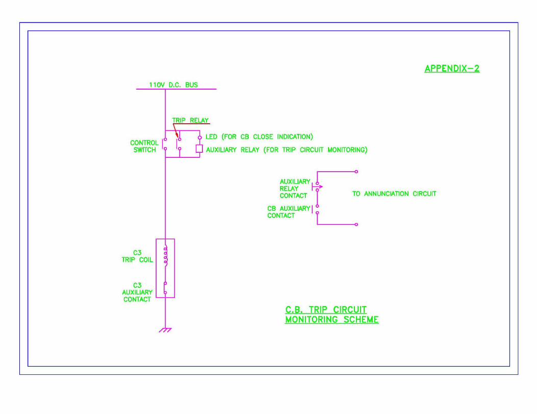
10.3 Trip-circuit supervision : The continuity and the availability of d.c. supply to the trip circuit of each
circuit breaker shall be monitored independently by an auxiliary relay connected in series with the trip coil of
the breaker. The current taken by the auxiliary relay shall not exceed 10 mA. Whenever the auxiliary relay de-
energises (while the breaker is in the closed position) either due to discontinuity in the trip circuit or d.c. supply
failure, a yellow LED (provided individually to the trip circuit of each breaker) and horn, both operated off
240V, single phase supply, shall come up. A push-button, in series with each of these auxiliary relays , shall be
provided by the side of the corresponding trip-circuit fail indication Led to test the healthiness of the supervision
and annunciation circuit. The scheme of connecting the auxiliary relay is shown in the sketch at Appendix-II.
10.4 Since the sub-station is unattended, necessary cut-off switches shall be provided on each control panel
for disconnection of the audio-visual alarms and annunciation & indication circuits to avoid un-necessary
drainage of the battery.
11 INDICATION AND ANNUNCIATION LEDs
11.1 Low consumption, extra bright, 5 mm dia, light emitting diodes (LEDs) shall be used wherever required.
The LEDs shall be suitably wired to glow off at 110V d.c. or 240V d.c. supply, as required.
11.2 LEDs shall be housed in suitable metallic holders with glazed/polished surface to act as reflector. The
holders shall be screwed to the panel from inside.
11.3 The following colour scheme shall be adopted for LEDs:
Signal for Colour of light
Circuit breaker/interrupter closed Red
Circuit breaker/interrupter open Green
Trip control of CB fail Yellow
Control or alarm & indication circuit d.c. supply fail Yellow
*Blower fans working Red
*The traction transformer may be provided with 240V, 50Hz, single-pahse operated blower fans for
forced cooling which start automatically in the event of winding temperature of transformer exceeding a preset
limit. For ease of connections, 3-4 blower fans are grouped together electrically. The number of groups for each
transformer may be 2 to 5. The temperature sensing is done by the WTI relay and suitable circuit for automatic
control of blows fans is provided in the marshalling box of the transformer. Indication LEDs one for each group
of blower fans shall be provided on the control panel, which shall light up when the blower fans of that group
are working. An N.O. type contact in each group of blowers circuit is provided for this purpose. The successful
tenderer shall ascertain from the purchaser, the actual number of groups provided for the transformer.
12. TEST AND TECHNICAL BLOCKS
12.1 Suitable test blocks shall be mounted conveniently inside th control board so as to be easily accessible.
The current rating of the contacts shall be 10 A continuous and 150 A for at least one second at 240V a.c. or d.c.
12.2 The current terminals shall be provided with short circuiting links or other suitable devices:
i) To short circuit the current transformer leads before interrupting the normal circuit for injection from
external source for testing (applicable for secondary injection tests of relays).
ii) To complete the current transformer circuit through a testing instrument in which ease the testing
instrument will be connected to the current terminals and the intermediate liml opened out (applicable for
checking indicating instruments with sub-standard meters at site).
12.3 The potential testing terminals shall preferably the housed in narrow respects of the mounted insulation
block to prevent accidental short circuits.
12.4 The arrangement of terminals shall be such that either portable type energy and maximum demand
meters, or trivector meters with printo-maxigraph for recording kW, kVA and kVAr can be concerned when
reputed.
12.5 Vertical or horizontal pillar stack type terminal blocks suitable for 1100 V service and not less than 30
amps rating shall be provided for terminating outgoing ends or control panel wiring and the corresponding
incoming tail ends of the control cables. Provision shall be made on each pillar for holding 20% extra
connections. The terminal blocks shall have individual identification markings which shall be either engraved or
made indelible by any other means. Pillars of terminal blocks meant for connections of incoming control and
indication cables shall be specially provided with identification labels indicating function(s) of each terminal
block.
12.6 The terminal of terminal blocks shall be of stud type suitable for terminating the ends of control wiring
and outgoing cable ends through crimped terminal spade/lugs, which shall be securely tighted with nuts and
spring washers. Suitable shrouds of unbreakable transparent material shall also be provided on each terminal
block.
12.7 Terminal blocks connected to potential circuits and current circuits shall not be placed adjacent to each
other in a pillar. When such segregation is not convenient due to any reason, a dummy spacer of insulating
material of adequate thickness or a space terminal block shall be provided in between two each circuits.
13. WIRING
13.1 All panel wiring shall be done with switch board type 1100 V grade PVC insulated single core, tinned
annealed stranded cooper conductor for service in extremely tropical climate. The PVC wires shall conform to
latest version/revision of IS:694 and duly tested for flammability test as per IS:10810(pt.53):1984. The wiring
shall also not be prone to attack by vermin, i.e. mice, white ants, cockroaches etc.
13.2 The size of wires in the meter and relay circuits connected to the current transformers shall be not less
than 4 sq.mm cooper and in potential and other circuits not less than 2.5 sq.mm cooper. The wires shall
stranded, composed of strands of not less than 0.91 mm (20 SWG).
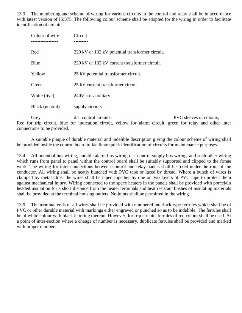
13.3 The numbering and scheme of wiring for various circuits in the control and relay shall be in accordance
with latest version of IS:375. The following colour scheme shall be adopted for the wiring in order to facilitate
identification of circuits:
Colour of wire Circuit
----------------- ---------
Red 220 kV or 132 kV potential transformer circuit.
Blue 220 kV or 132 kV current transformer circuit.
Yellow 25 kV potential transformer circuit.
Green 25 kV current transformer circuit
White (live) 240V a.c. auxiliary
Black (neutral) supply circuits.
Grey d.c. control circuits. PVC sleeves of colours,
Red for trip circuit, blue for indication circuit, yellow for alarm circuit, green for relay and other inter
connections to be provided.
A suitable plaque of durable material and indelible description giving the colour scheme of wiring shall
be provided inside the control board to facilitate quick identification of circuits for maintenance purposes.
13.4 All potential bus wiring, audible alarm bus wiring d.c. control supply bus wiring, and such other wiring
which runs from panel to panel within the control board shall be suitably supported and clipped to the frmae
work. The wiring for inter-connections between control and relay panels shall be fixed under the roof of the
conductor. All wiring shall be neatly bunched with PVC tape or laced by thread. Where a bunch of wires is
clamped by metal clips, the wires shall be taped together by one or two layers of PVC tape to protect them
against mechanical injury. Wiring connected to the space heaters in the panels shall be provided with porcelain
headed insulation for a short distance from the heater terminals and heat resistant bushes of insulating materials
shall be provided at the terminal housing outlets. No joints shall be permitted in the wiring.
13.5 The terminal ends of all wires shall be provided with numbered interlock type ferrules which shall be of
PVC or other durable material with markings either engraved or punched so as to be indelible. The ferrules shall
be of white colour with black lettering thereon. However, for trip circuits ferrules of red colour shall be used. At
a point of inter-section where a change of number is necessary, duplicate ferrules shall be provided and marked
with proper numbers.
13.6 Ends of all wires shall be provided with terminal spades (tanned) which shall be crimped into the wires.
At terminal connections, washers shall be interposed between wire terminals and holding nuts. The connection
studs shall project at least 3 mm from the lock-nut surface. Wire ends shall be so connected at the terminal studs
that no terminal ferrule gets marked due to the succeeding connections. The wire ends shall be suitably bent to
meet the terminal stud at right angles with the stud axis; skew connections shall not be permitted.
14. FUSES AND LINKS
14.1 HRC slyde-lock type fuses of adequate current rating shall be provided in all potential circuits. Fuse
bases and carriers shall be mounted in the interior of the control board and at easily accessible places. The fuse
rating and the identification number, a assigned in the schematic diagram, shall be indicated on the fuse carriers.
Suitable labels with engraved markings indicating the rating, identification number and the circuit in which used
shall also be provided below the fuse bases.
14.2 The links provided in the circuits either on negative/neutral side or for branching purposes, shall also be
of slyde-lock type similar to fuses mentioned above, except that these shall be provided with tinned cooper strip
of suitable size in place of HRC fuse. The disk identification number as assigned in the schematic diagram shall
be indicated in the link carrier. The link base shall also be identified in the similar manner as the fuse base
mentioned in Clause 14.1.
15. SPACE HEATERS AND CONTROL BOARD LIGHTING
15.1 Suitable space heaters to operate off 240V single phase supply with ON/OFF switches shall be provided
inside the control board to prevent condensation of moisture in humid whether.
15.2 The interior of control board enclosure shall be adequately lighted by incandescent lamps connected to
240 V single phase supply. The central corridor shall be illuminated by a lamp controlled by the door switches
provided on the doors on either side of the corridor. Each section of the control and relay panels shall also be
illuminated, controlled by separate switches.
15.3 Two sets, one each for relay panels and control panels, of 5 Amp, single phase, 3 pin plug sockets with
switches shall be provided inside the control board at convenient points for use of portable lamps.

16. EARTHING
16.1 All current free metallic bodies of equipment/relays etc. on the control board shall be earthed properly.
Main earth circuit shall be of 25 x 3 mm tipped cooper strip and individual connections of equipment/relays
with main earth circuit shall be by means of 2.64 mm (12SWG) tipped annealed cooper bare conductor/strips,
using tinned cooper spade terminals/lugs. Alternatively, PVC insulated stranded tinned cooper wire of size
equivalent to 2.64 mm (12 SWG) can also be provided. Joints shall be avoided as far as possible.
16.2 In order to facilitate the earthing of secondaries of CTs and PTs inside the control board, suitable earth
links of adequate size made of tinned cooper/brass shall be provided inside the control board at the appropriate
points.
16.3 Multiple earthing of current/potential transformer circuits shall be avoided. Main earth connection for
each panel shall be brought out to two terminals for connection to the general earthing system.
17. NAME PLATES/IDENTIFICATION LABELS
17.1 All relays, instruments and other electrical devices mounted on the board shall have name plates with
rating data, serial number and manufacturer‟s name.
17.2 Identification labels of size 65 x 13 mm bearing identification marks indicating functions of respective
equipments shall be provided on the exterior of control and relay panels under all the relays, instruments and
test blocks etc. Similar labels shall also be provided under the switches where necessary.
17.3 Identification labels of size 25 x 25 mm bearing identification marks indicating numbering of respective
equipments shall be provided besides the semaphores, power transformer and auxiliary transformer positions
and control panels. The control and local/remote selector switches shall be provided with suitable labels duly
inserted in their pockets available for the purpose. The scheme of numbering of various equipments in traction
sub-stations shall be supplied by the Purchaser.
17.4 All push buttons on the control board shall have suitable inscription on the collars indicating the
functions of each push button, and where such collars are not available, separate indicating labels of PVC sheet
of suitable width and length not more than the overall outside dimension of the push buttons shall be provided.
Similarly, the function of each indicating annunciation LED shall be indicated by a label of elegant and
appropriate size provided alongside/alongwith the concerned LED holder.
17.5 Plastic plates about 50 mm wide, bearing suitable captions to identify the transformer bay and
corresponding outgoing 25 kV feeder, shall be provided on the top of each relay and control panel.
17.6 All the identification labels on the exterior of control and relay panels shall be incurred with the help of
chromium plated metallic screws.
17.7 Identification labels shall also be provided in the interior of the control board. For such of the equipment
and fittings which are exclusively mounted inside the control board, the labels of suitable size indicating
function of respective equipment shall be provided under each. Whereas the labels inside the control board for
the equipment mounted flush/semi-flush outside the control and relay panels, shall bear reference index code
corresponding to the schematic diagrams.
17.8 The labels inside the panels can be secured with the help of adhesive of good quality (wherever
necessary). The labels in the interior of the board under the equipments/relays shall be so provided that they are
not obscured due to bunches of wire runs and any other obstructions. Painting of inscriptions shall not be
permitted.
17.9 All inscriptions on the labels to the fixed on the control and relay panels shall be made on the PVC sheet
strip of black background with white engraved letters/figures. However, the labels to be fixed inside the panels
may be either on engraved letterings or of aluminium anadized screen printed type.
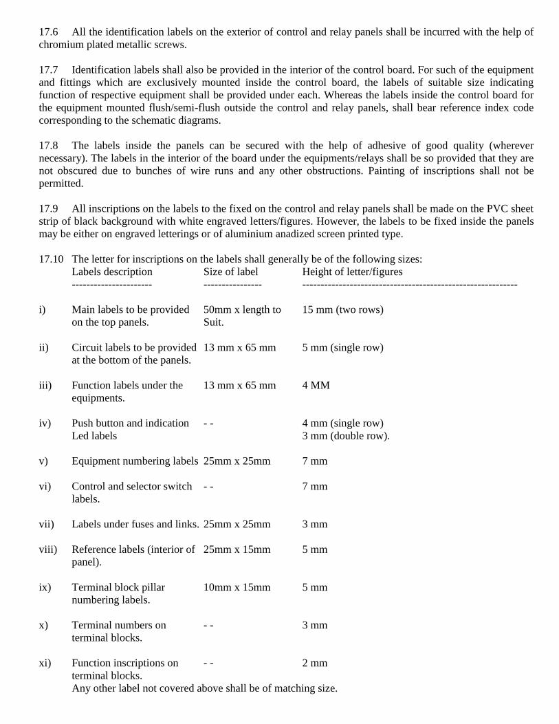
17.10 The letter for inscriptions on the labels shall generally be of the following sizes:
Labels description Size of label Height of letter/figures
---------------------- ---------------- -----------------------------------------------------------
i) Main labels to be provided 50mm x length to 15 mm (two rows)
on the top panels. Suit.
ii) Circuit labels to be provided 13 mm x 65 mm 5 mm (single row)
at the bottom of the panels.
iii) Function labels under the 13 mm x 65 mm 4 MM
equipments.
iv) Push button and indication - - 4 mm (single row)
Led labels 3 mm (double row).
v) Equipment numbering labels 25mm x 25mm 7 mm
vi) Control and selector switch - - 7 mm
labels.
vii) Labels under fuses and links. 25mm x 25mm 3 mm
viii) Reference labels (interior of 25mm x 15mm 5 mm
panel).
ix) Terminal block pillar 10mm x 15mm 5 mm
numbering labels.
x) Terminal numbers on - - 3 mm
terminal blocks.
xi) Function inscriptions on - - 2 mm
terminal blocks.
Any other label not covered above shall be of matching size.
18. TESTS
18.1 General
18.1.1 Only after all the designs and drawings have been approved and clearance given by RDSO to this effect,
the manufacturer shall take up the manufacture of the prototype for RDSO inspection. It shall be clearly
understood that any changes required to be done in the prototype as required by RDSO shall be done
expeditiously.
18.1.2 Before giving the call to RDSO/the Chief Electrical Engineer for inspection and testing of the prototype
of the system, the manufacturer shall submit a detailed test schedule consisting of schematic circuit diagrams for
each of the tests and nature of the test, venue of the test and the duration of each test and the total number of
days required to complete the test at one stretch. Once the schedule is approved, the test shall invariably be done
accordingly. However, during the process of type testing or even later, RDSO representative reserves the right
to conduct any additional test (s) besides those specified herein, on any equipment/sub-system or system so as to
test the system to his satisfaction or for gaining additional information and knowledge. In case any dispute or
disagreement arises between the manufacturer and RDSO, the Chief Electrical Engineer during the process of
testing as regards the type tests and/or the interpretation and acceptability of the type test results, it shall be
brought to the notice of the Director General (Traction Installations), RDSO/the Chief Electrical Engineer as the
case may be, whose decision shall be final and binding.
18.2 Type test: The relays shall be type tested as per IS:3231-1965 and IS:8686-1977, and any other relevant
standards. All instruments, interposing CTs and any other equipments as the purchaser may desire shall be type
tested as per the latest version of respective standard IS/BS Specification applicable.
18.2.1 Temperature rise test: The temperature rise of the coil of the relay shall not exceed the limits of 55 deg.
C and 80 deg. C for Class-A and Class-B insulation respectively.
18.2.2 If the prototype of the relays and other equipments conforming to this specification has already been
approved in connection with previous supplies to Indian Railways. Fresh prototype testing may be waived if fit
had passed the prototype tests earlier and no changes in the design or material used have been made.
18.3 Routine tests: All relays, instruments, interposing CTs and other equipments shall be subjected to routine
tests at the manufacturer‟s works as per the relevant standards.
18.4 The following checks and tests shall be carried out on the complete control and relay board:
i) Visual checks:
General check of the control board in respect of construction, wiring, provision of various
equipments/relays etc.
ii) Operation tests:
Operation tests on all equipments, switches and tests on prove correctness of wiring of various
circuits including indications, alarms, operation of relays and annunciation etc.
iii) P.F. high voltage withstand tests:
Voltage test on the panels with all equipments and wiring of for a withstand voltage of 2 kV
(rms) to earth for one minute.
iv) Insulation resistance tests:
Measurement of insulation resistance of the complete panel wiring and circuit by circuit, with all
equipments mounted on the panel, by using 1000 V megger.
18.5 Only after clear written approval of the results of the tests on the prototype is communicated by
RDSO/Purchaser to the manufacturer, shall be taken up bulk manufacture of the equipment which shall be
strictly with the same material and process as adopted for the prototype. In no circumstances shall material other
than those approved in the designs/drawings and/or the prototype be used for bulk manufacture on the plea that
they had been obtained prior to the approval of the prototype.
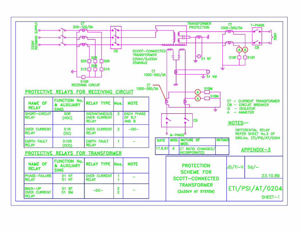
19. SCHEME OF PROTECTION FOR 220 OR 132 KV SCOTT-CONNECTED SINGLE PHASE
TRANSFORMER
19.1 For protection of 220 or 132 kV Scott-connected single phase transformer, the following relays be
provided on the relays panels.
-----------------------------------------------------------------------------------------------------------------------------------
Name of relay Function No. Relay type Nos. Note
-----------------------------------------------------------------------------------------------------------------------------------
i) For Receiving Circuit:
Short circuit relay 50R (HOC) Instantaneous over current 2 (3)* Each phase of R, Y
Relay and B.
Over current relay 51R (OC) Over current relay 2 (3)* -do-
Earth fault relay 51CR (OCG) Earth fault relay 1 - -
ii) For Transformer:
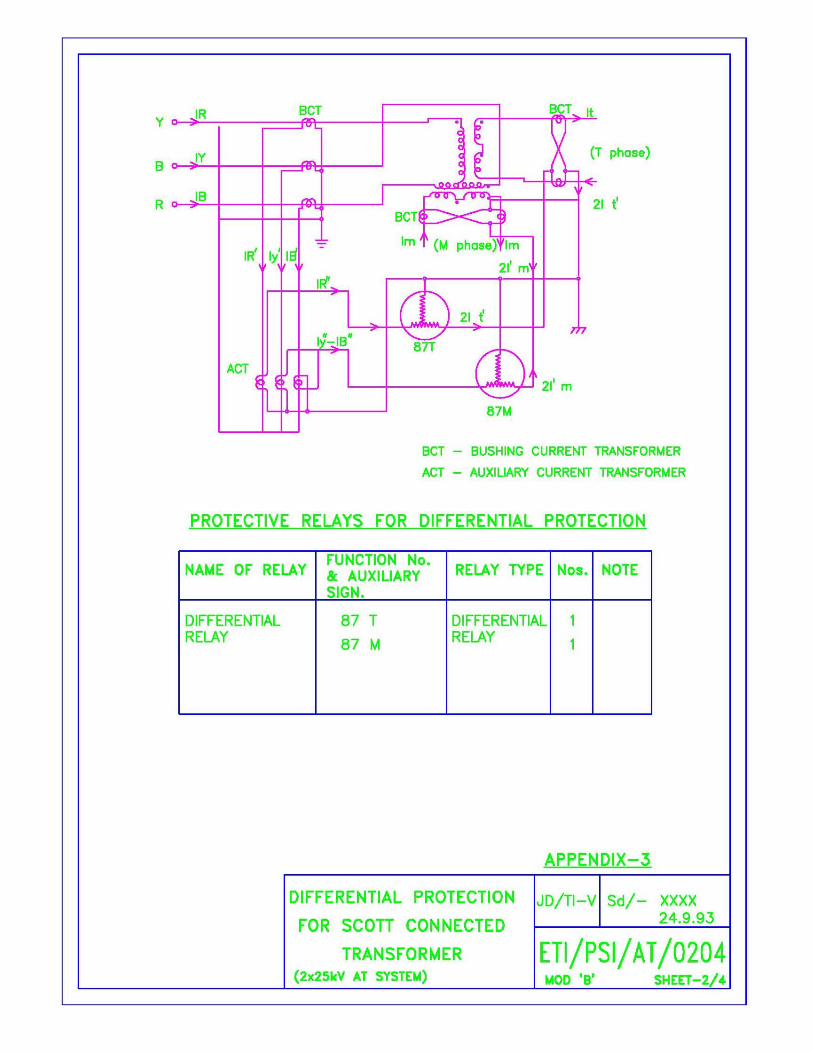
Differential relay 87T (87T, 87N)*
Differential relay 1 (2)* - -
Phase Failure relay 51NT (51NT, 51NM) *
Over current relay 1 (2)* - -
Back-up over current relay 51B (51BT, 51BM) *
Over current relay 2(4)*` - -
-----------------------------------------------------------------------------------------------------------------------------------
*The Nos. given inside the breakers are for Scott-connected Transformers.
The protection scheme is shown in the drawing at Appendix-III. The requirements of the protective
relays are given in Clause-19.3
19.2 Other protective devices.
The transformer as supplied by the purchaser will be fitted with the following warning and protective
devices:
(i) Low oil level alarm.
(ii) Buchholz relay with alarm and trip contacts.
(iii) Oil temperature indicator with alarm and trip contacts.
(iv) Winding temperature indicator with alarm and trip contacts..
(v) Pressure relief device with alarm and trip contacts..
These contacts will be wired up to a whether proof terminal box mounted on the transformer by the
transformer manufacturer. The connection shall be extended to the alarm and trip contacts as well as to
annunciator provided on the control panel by the successful tenderer.
19.3 Protective Relays.
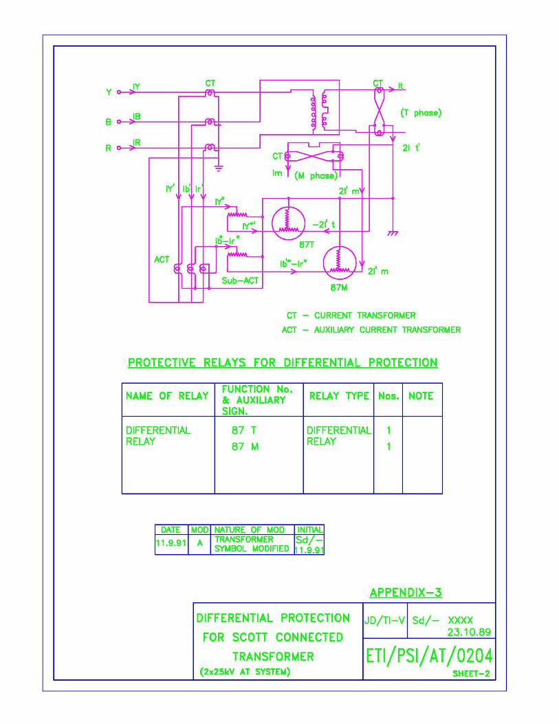
19.3.1 Differential protection: Protection against internal faults in the transformer shall be provided by means
of sensitive differential relays. The relay shall be of the high speed type and operate in less than 2 cycles (40
ms). The relay shall incorporate the following features:
i) There shall be no necessity for changing the setting of the relay when the transformer tap is
changed. The transformer is provided with taps from –15% to +10%.
ii) Necessary harmonic restraining features shall be incorporated to prevent operation due to in-rush
of magnetization current, when the transformer is charged either from the HV or DV side.
iii) The relay shall not operate for maximum through fault current.
iv) The current settings of the relay shall be adjustable preferably between the range of 20% to 80%.
The minimum current settings shall be as low as possible to obtain better sensitivity.
v) Adjustable bias setting shall also be provided. The bias at minimum operating current setting
shall be 20%, 30% and 40% to suit tapping range of the traction transformer and other design
considerations.
The relay shall be connected to bushing type current transformers provided in the bushings of the
traction transformers. Interposing current transformers of suitable ratio and rating with matching characteristics
of knee point voltage, excitation current etc. shall be provided with the differential relay in order to boost-up the
bushing CTs secondary currents at full load to a value equal to rated relay current. Magnetization and ratio error
curves will be supplied to the successful tenderer to enable him to match the characteristics of the relays and
interposing CTs with those of the bushing CTs.
19.3.2 Earth leakage protection: Protection against earth leakage currents shall be provided by means of an
inverse time earth fault relay provided on the primary side of the traction transformer. The current setting of the
relay shall be continuously adjustable between that and the time setting at join –1 to 20.
19.3.3 Over current protection: Protection against over current in the transformer shall be provided by means of
over-current relays with inverse definite minimum time lag characteristics both on the primary and secondary
sides of the transformer. Further, instantaneous (high-speed) over current relays shall be provided on the
primary side. The relays shall be connected to separately mounted current transformers. The over-current relays
on the secondary side shall serve as back-up protection against faults in the 25 kV overhead equipment and also
against bus faults. The over current relays on the primary side shall serve as back-up to the over current relays
on the secondary side as well as back-up to differential and earth fault relays against heavy faults. Proper
discrimination shall be maintained in the operation of these two sets of over current relays. The setting on these
relays shall be continuously adjustable between:
Current setting Time setting
------------------ ---------------
i) IDMT over-current relay on primary side. 80% 0 to 3 sec.
320%.
ii) Instantaneous over-current relay on primary side. 400% to -
1600%
iii) IDMT over-current relay on secondary side. 80% 0 to 3 sec.
320%.
The instantaneous relays shall be of T10 Class with operating time not exceeding 10 ms at 5 times the current
setting.
19.3.4 Phase failure relay: Neutral tape of secondary windings of traction transformers will be directly (or
through series capacitor) connected to rail and earth. The two outer terminals of a secondary winding will be
connected to two pole feeder circuit breaker through a two pole feeder circuit breaker on the secondary circuit of
the transformer. If either of two pole of the circuit breakers does not close or open in its operation, power will be
fed to load from half of the secondary winding. The phenomenon is called here as “phase failure”.
Detection of phase failure shall be provide by means of a inverse time over current relay, with current
settings continuously adjustable between 10 to 40% and time setting between 0 to 20 sec, installed on the
neutral circuit as shown in enclosed drawings at Appendix-III.
19.3.5 The differential relay. Earth fault relay, instantaneous and over current relays on the primary side, as also
the phase failure phase failure relay on the secondary side, shall cause inter-tripping of the 220/132 and 25 kV
circuit breakers associated with the transformer. The inter-tripping of the circuit breakers shall be effected due
to other faults in the transformer, viz. Buchholz trip, excessive winding temperature and excessive oil
temperature trip, and pressure relief device trip. The IDMT over-current relay on the secondary side shall
however trip the respective circuit breaker on 25 kV side only. The inter-tripping of associated transformer
circuit breakers envisaged above shall be effected through high speed tripping relay with hand reset contacts.
Such inter-tripping relay shall lock out the closing of circuit breakers from all modes of closing commands viz.
remote control, local control at the panel and also at the circuit breaker mechanism, until the inter-trip relay or
the lock out relay (if provided separately) is reset manually.
19.4 Co-ordination with equipment manufacturers.
The successful tenderer shall ensure necessary co-ordination with the manufacturers of transformers,
circuit breakers and interrupters with regard to terminal marking, wiring, scheme of protection etc. He shall
obtain the names of these manufacturers from the Purchaser.
20. SCHEME OF PROTECTION FOR 25 KV OVERHEAD EQUIPMENT
20.1 The substation equipment as well as the overhead equipment is protected against short circuits and over-
loads by means of feeder circuit breakers. Normally the tracks on side of the substation are fed through one
feeder circuit breaker, while another circuit breaker being as standby. In case of defect on one feeder, the other
feeder circuit breaker is arranged to feed. Hence, in a double line-section, there are four feeder circuit breakers.
The protection scheme shall fulfill the following function:
i) To detect all short circuits over the zone of overhead equipment fed by the feeder circuit breaker.
ii) To operate with minimum delay in opening the circuit breaker.
iii) To refrain from operation at the maximum working current, i.e. to discriminate between the
maximum load current and short circuit currents even through the magnitude of the former is at
times more than the latter especially when the faults are remote d\from the substation.
iv) To detect and isolate faults on the OHE caused by accidental coupling of two differential phases
from adjacent sub-station.
v) to provide a single phase shot auto-re-closing scheme for the feeder circuit breaker after a preset
time interval adjustable between 0.5 sec. To 5 sec. For re-closing the 25 kV feeder circuit breaker
automatically in the event tripping on fault through any of the protective relays viz. distance
relay, Delta I type fault selective relay and instantaneous over current relay.
20.2 The normal zone of feed of a substation to neutral section varies from 40 to 50 km. Under emergency
feed conditions, however, the zone would extend upto the next substation by closing the bridging circuit
breakers at the sectioning post, and will be about double the zone normal feed. It will be apparent from the
impedance values given in Clause 2.5 that the fault current under such conditions could be well below the
traction load current. Over current or plain impedance relays which operate below a certain impedance level and
which function independently of the phase angle between voltage and current, will be unable to discriminate
such faults. Therefore, a relay working on the principle of discrimination of the argument of the impedance is
required.
20.3 The protective system shall, therefore, comprise the following relays:
i) A distance relay (21F) with parallelogram protection characteristics to cover the entire zone of
protection i.e. from the substation to the adjacent substation and to operate for any earth faults on
the overhead equipment in the zone. This relay shall conform to RDSO‟s specification No.
ETI/PSI/129(8/89).
ii) A Delta I type fault selective relay (50DF), working on the principle of discriminate of fault
current based on the rate of change of current. This relay shall conform to RDSO‟s Specification
No.ETI/PSI/130(8/89).
iii) An instantaneous over current relay (50F) with continuously adjustable current setting between
100 to 400%. The relay shall be of T10 Class with operating time not exceeding 10 ms at 5 times
the current setting
The above relays, provided separately for each feeder circuit breaker, shall trip the corresponding feeder
circuit breaker in case of fault, through a high speed self-reset type tripping relay to be designated as Matter trip
relay. The above relays, provided separately for each feeder circuit breaker, shall trip the corresponding feeder
circuit breaker in case of fault, through a high speed self-reset type tripping relay to be designated as Matter trip
relay.
20.4 Suitable operation counters shall also be provided individually for each of the above three relays.
20.5 Under-voltage relay: An under-voltage relay, provided individually for each of the OHE PTs, operated
off the OHE PT shall be provided by the successful tenderer. The under-voltage relay shall prevent closure of
the concerned feeder circuit breaker, when the OHE is already in the energized condition (for example, during a
feed extension) to avoid any wrong phase coupling between different sub-stations.
20.6 A single-shot auto-reclosing relay shall also be provided by the successful tenderer for each feeder
circuit breaker, as per RDSO‟s Specification No.ETI/PSI/136(8/89).
20.7 In addition the above protection, an instantaneous acting under voltage relay is provided by the
Purchaser to trip the circuit breaker at the sectioning post in case of under-voltage during emergency feed
conditions.
20.8 The relays shall conform to accuracy class 15 as per IS:3231-965.
20.9 The polarizing input for relays shall have a tuned memory circuit, so that it is possible to maintain a
polarizing signal after a fault occurs, for a sufficiently long time for the relay to operate in case of a fault close
to the sub-station, when the restarting voltage disappears.
20.10 The relays shall be insensitive to power swings, heavy overloads and transient conditions including
magnetizing inrush current of locomotive transformers and auto- transformers, and shall be suitably designed to
complete the effect of fault are resistance.

21. PARTICULARS OF POTENTIAL AND CURRENT TRANSFORMERS
21.1 The relays for transformer and OHE protection shall be suitable for operation from current and potential
transformers to the following particulars:
-----------------------------------------------------------------------------------------------------------------------------------
PARTICULARS
-----------------------------------------------------------------------------------------------------------------------------------
Equipment Ratio Burden Class of rated accuracy limit factor as per IS:2705
-----------------------------------------------------------------------------------------------------------------------------------
(1) Bushing CTs:
i) 220/50 kV transformer.
HV 200/5 30VA PS Class ------
LV 1000/5 30VA PS Class ------
ii) 132/50 kV transformer.
HV 200/5 30VA PS Class ------
LV 1000/5 30VA PS Class ------
220 kV CT 300-150/5 30VA 5P 15
200-100/5 30VA 5P 15
132 kV CT 200-100/5 30VA 5P 15
300-150/5 30VA 5P 15
iii) Separately mounted CTs on LV side:
25 kV CT 1000-500/5 60VA 5P 15
1500-750/5 60VA 5P 15
(IS:2705 Pt-
III, 1981)
iv) Potential transformer on LV side:
25 kV PT 27000/110 V 100VA 1.0/3P
(as per IS:3156-
Pt-II&III,1978)
-----------------------------------------------------------------------------------------------------------------------------------
The exact details of the above transformers are given in the relevant sub-station Tender papers, which
shall be referred to be the Tenderer before making his offer. Any additional requirements of CTs and PTs (like
knee-point voltage of CTs), if any, shall be clearly indicated in the tender offer.
21.2 The location of various potential and current transformers in the circuit is indicated in the layout
drawings of traction sub-stations, given in the relevant sub-station tender papers. The drawings indicating the
proposed scheme of connection at the sub-stations for the instruments and protective relays are also given in the
relevant sub-station tender papers. The tenderer may, however, furnish alternative proposals, if any, for
consideration of the Purchaser.
21.3 The normal load current of the 25 kV circuit is 500 or 400 A with 50 MVA Scott-connected or 20 MVA
single-phase transformers respectively. The circuits including the transformers are, however, designed to take
50% overload for 15 minutes and 100% overload for 5 minutes. Normally, 500/5A, CT ratio would be used in
the instrument and relay circuits for 25 kV current transformers.
NOTE: The two transformers in a substation may be operated in parallel if required due to increase in
load. To enable this, dual ratio 25 kV current transformers (1000-500/5) have been specified.
22. FACILITIES FOR INTER-CONNECTION WITH SUPERVISORY (REMOTE) CONTROL AND
DATA ACQUITION (SCADA)EQUIPMENT:
22.1 The successful tenderer shall provide facilities for inter-connection with the supervisory remote
control equipment as mentioned in the following paragraphs
22.2 Control of switch-gears: The traction sub-stations being of un-attended type, the control of all
circuit breakers, interrupters and motor operated isolators (if any) is normally effected from Remote Control
Center (RCC) through the Supervisory Remote Control Equipment (to be provided by the Purchaser under a
separate contract). The operation of the controlled equipments through SRC equipment is possible when the
associated local/remote selector switch on the control panel is kept in “Remote” mode. For this purpose, the
successful tenderer shall provide necessary wiring from the local/remote selector switches and terminate on
the thermal blocks to which inter-connecting control cables from Remote Control Equipment at TSS can be
connected.
22.3 Tele-signaling of informations:
The following information is required to be tele-signaled to the RCC for monitoring the status and health
of the sub-station.
a) Status indications of switch-gears:
i) ON/OFF of circuit breakers, interrupters and monitor operated isolators (if any).
ii) Tele-signaling the lock out condition of the SF-6 gas circuit breakers to remote control center.
SF-6 gas circuit breakers are provided at the traction sub-stations. In case of fall/loss of air pressure or
gas pressure below the preset limits, the circuit breakers automatically gets locked out in the open condition.
Necessary contacts in the control circuits in the circuit breaker mechanism are available for signaling of the
locked out condition..
b) Tele-signaling of transformer faults/alarms etc.:
For Transformer-I
i) TR-1 Fault.
ii) TR-1 Alarm.
iii) TR-1 Trip circuit fail.
For Transformer-263 (as applicable) : b) Tele-signaling of transformer faults/alarms etc.:
For Transformer-I
i) TR-1 Fault.
ii) TR-1 Alarm.
iii)TR-1 Trip circuit fail.
For Transformer-263 (as applicable):
Same as for transformer-1
Common for TR-1, TR-2 & TR-3
TR-1/TR-2/TR-3 110V d.c. supply for alarm circuits fail.
TR alarm: This has to come whenever any alarm viz. Buchholz alarm, oil winding temp. high alarm,
pressure relief device alarm and low oil level alarm occurs.
TR fault: This has to come whenever the inter-trip relay (whitch trips both HV and LV breakers of the
transformer) operation.
TR trip circuit fail: whenever the 110Vdc supply to the concerned control circuit fails, or any of the trip-
circuits of HV & LV breakers fail.
c.) 25 kV feeder protective relay:
i.) For CB DPR operated.
ii.) For CB OCR operated.
iii.) For CB Delta-I operated.
The above tele-signals shall be provided for each feeder separately.
22.4 Telemeterng od current, voltage etc.
For the purpose of tele-metry to the RCC , all the potential & current transformer terminations shall be
provided on a terminal board. The CT terminations shallbe shoted using links. By re-arranging the links,
it shall be possible to connect the current circuits of the transducers of the remote control equipment in
series with the relays etc. of the control board.
22.5 Auto-reclosing scheme:
The auto-reclosing scheme as mentioned in clause 20.6 shall be inter-connected to remote control
equipment for telesignalling the „locked out‟ condition of the auto-recloser to RC Centre and for
resetting the same through telecommand from the PˆC. for this purpose, necessary terminations on
terminal blocks shall be provided.
22.6 Motorised off-circuit Transformer tap changer:
The traction transformers at the substation may be fitted with motor operated off-circuit R.P. changer
with its associated 110V d.c. control circuit. The wiring for control of tap-changer and indication of tap
position shallbe terminated on a terminal control equipment. However, no control or indication is
required on the controlboard.
22.7 All the terminations required for inter-connection with the remote control equipment at TSS shall be
suitable terminal blocks and be provided with clear identification labels. The drawing at annexure-IV
shows the termination arrangement.

23. TECHNICAL DATA, LITERATURE & DRAWINGS:
23.1 The tenderer shall furnish the make, type & guaranteed performance, technical and other particulars for all
equipments/relays/. Instruments etc. including control/relay panel details, envisaged in this specification and
offered by the tenderer, in the perform attached as Annexure-B to this specification. The tenderer shall also
furnish the technical specification and descriptive literature of various relays, instruments, interposing CTs etc.
including the characteristics of the relays offered. He shall also submit, alongwith the tender, the schematic
diagram of protection, control and annunciation scheme to enable the purchaser to make assessment of the
proposal.
23.2 The information furnished in the Schedule of guaranteed performance, technical and other particulars
(Annexure-B) shall be complete in all respects. If there is any entry like “shall be furnished later” or blanks are
left against any item, the tender is not likely to be considered as such omissions cause delay in finalizing the
tender.
23.3 The tenderer shall indicate his complete or otherwise against each clause/sub-clause of this specification.
The tenderer shall for this purpose enclosure a separate statement, if necessary, indicating the clause/sub-clause
reference and compliance or otherwise thereof. Wherever the tenderer deviates from the provision of the
clause/sub-clause or offers any alternative equipment, he shall furnish complete details of the proposed
deviation/alternative with his remarks to enable the purchaser to make proper assessment of the same. The
successful tenderer shall, however, be required to obtain specific acceptance of the purchaser for any
deviation/alternative proposed by them.
23.4 Successful tenderers shall be required to submit the following detailed dimensional drawings (including
reproducible copies) as per Railways standard sizes of 210 x 297 mm or multiples thereof, for approval.
i) Dimensional drawings of the control board indicating front and rear views with the layout of
instruments, mimic diagram, control switches, indicating LEDS, push buttons, relays and other
equipments etc. clearly marked.
ii) Exploded view of the rear and front panels indicating the disposition of various equipments
inside the control board.
iii) Schematic diagram of d.c. control circuits for transformer protection, OHE protection and control
of circuit breakers, interrupters and motor-operated isolators (if any).
iv) Schematic diagram of alarm and indication circuit (annunciation scheme).
v) Schematic diagram of d.c. circuits showing connection of CTs and PTs and associated protective
relays.
vi) Drawings showing the legend of various reference/codes adopted for equipments, relays and all
other accessories used in control board.
vii) Drawing for name plates/identification labels engraving details.
viii) Any other drawings considered necessary.
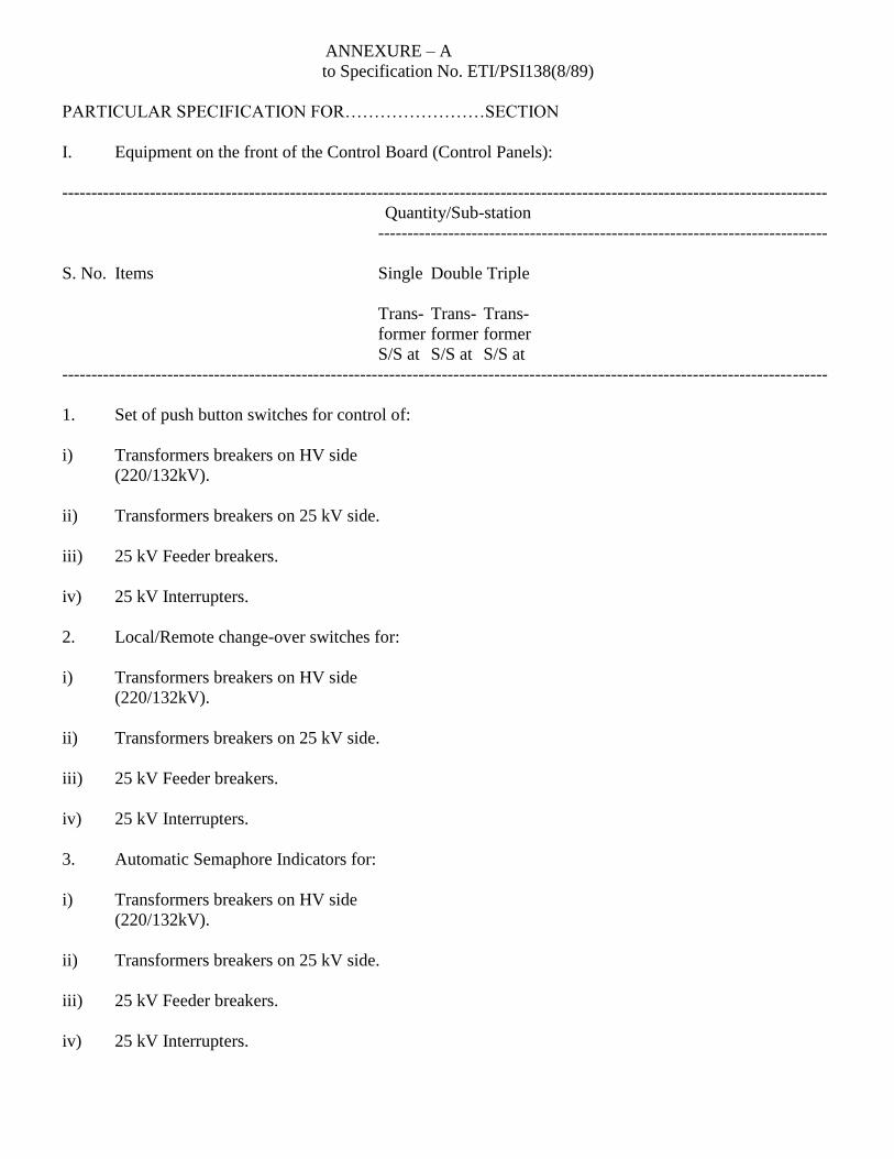
ANNEXURE – A
to Specification No. ETI/PSI138(8/89)
PARTICULAR SPECIFICATION FOR……………………SECTION
I. Equipment on the front of the Control Board (Control Panels):
-----------------------------------------------------------------------------------------------------------------------------------
Quantity/Sub-station
-----------------------------------------------------------------------------
S. No. Items Single Double Triple
Trans- Trans- Trans-
former former former
S/S at S/S at S/S at
-----------------------------------------------------------------------------------------------------------------------------------
1. Set of push button switches for control of:
i) Transformers breakers on HV side
(220/132kV).
ii) Transformers breakers on 25 kV side.
iii) 25 kV Feeder breakers.
iv) 25 kV Interrupters.
2. Local/Remote change-over switches for:
i) Transformers breakers on HV side
(220/132kV).
ii) Transformers breakers on 25 kV side.
iii) 25 kV Feeder breakers.
iv) 25 kV Interrupters.
3. Automatic Semaphore Indicators for:
i) Transformers breakers on HV side
(220/132kV).
ii) Transformers breakers on 25 kV side.
iii) 25 kV Feeder breakers.
iv) 25 kV Interrupters.
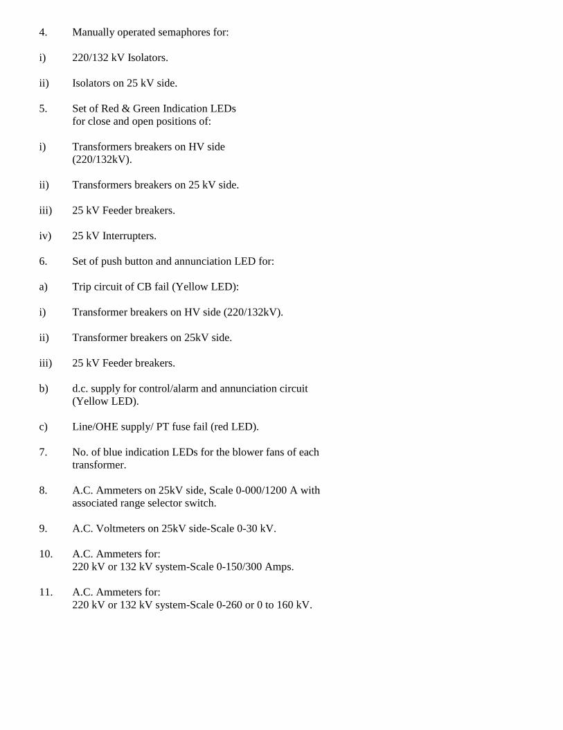
4. Manually operated semaphores for:
i) 220/132 kV Isolators.
ii) Isolators on 25 kV side.
5. Set of Red & Green Indication LEDs
for close and open positions of:
i) Transformers breakers on HV side
(220/132kV).
ii) Transformers breakers on 25 kV side.
iii) 25 kV Feeder breakers.
iv) 25 kV Interrupters.
6. Set of push button and annunciation LED for:
a) Trip circuit of CB fail (Yellow LED):
i) Transformer breakers on HV side (220/132kV).
ii) Transformer breakers on 25kV side.
iii) 25 kV Feeder breakers.
b) d.c. supply for control/alarm and annunciation circuit
(Yellow LED).
c) Line/OHE supply/ PT fuse fail (red LED).
7. No. of blue indication LEDs for the blower fans of each
transformer.
8. A.C. Ammeters on 25kV side, Scale 0-000/1200 A with
associated range selector switch.
9. A.C. Voltmeters on 25kV side-Scale 0-30 kV.
10. A.C. Ammeters for:
220 kV or 132 kV system-Scale 0-150/300 Amps.
11. A.C. Ammeters for:
220 kV or 132 kV system-Scale 0-260 or 0 to 160 kV.
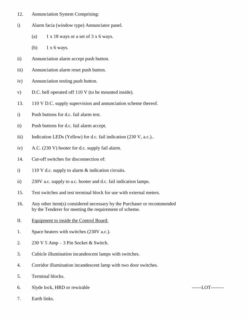
12. Annunciation System Comprising:
i) Alarm facia (window type) Annunciator panel.
(a) 1 x 18 ways or a set of 3 x 6 ways.
(b) 1 x 6 ways.
ii) Annunciation alarm accept push button.
iii) Annunciation alarm reset push button.
iv) Annunciation testing push button.
v) D.C. bell operated off 110 V (to be mounted inside).
13. 110 V D.C. supply supervision and annunciation scheme thereof.
i) Push buttons for d.c. fail alarm test.
ii) Push buttons for d.c. fail alarm accept.
iii) Indication LEDs (Yellow) for d.c. fail indication (230 V, a.c.)..
iv) A.C. (230 V) hooter for d.c. supply fail alarm.
14. Cut-off switches for disconnection of:
i) 110 V d.c. supply to alarm & indication circuits.
ii) 230V a.c. supply to a.c. hooter and d.c. fail indication lamps.
15. Test switches and test terminal block for use with external meters.
16. Any other item(s) considered necessary by the Purchaser or recommended
by the Tenderer for meeting the requirement of scheme.
II. Equipment to inside the Control Board:
1. Space heaters with switches (230V a.c.).
2. 230 V 5 Amp – 3 Pin Socket & Switch.
3. Cubicle illumination incandescent lamps with switches.
4. Corridor illumination incandescent lamp with two door switches.
5. Terminal blocks.
6. Slyde lock, HRD or rewirable ------LOT--------
7. Earth links.
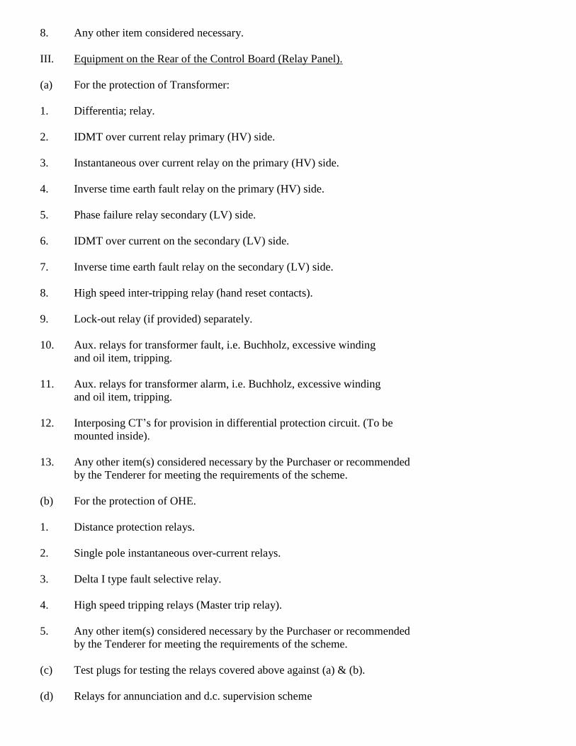
8. Any other item considered necessary.
III. Equipment on the Rear of the Control Board (Relay Panel).
(a) For the protection of Transformer:
1. Differentia; relay.
2. IDMT over current relay primary (HV) side.
3. Instantaneous over current relay on the primary (HV) side.
4. Inverse time earth fault relay on the primary (HV) side.
5. Phase failure relay secondary (LV) side.
6. IDMT over current on the secondary (LV) side.
7. Inverse time earth fault relay on the secondary (LV) side.
8. High speed inter-tripping relay (hand reset contacts).
9. Lock-out relay (if provided) separately.
10. Aux. relays for transformer fault, i.e. Buchholz, excessive winding
and oil item, tripping.
11. Aux. relays for transformer alarm, i.e. Buchholz, excessive winding
and oil item, tripping.
12. Interposing CT‟s for provision in differential protection circuit. (To be
mounted inside).
13. Any other item(s) considered necessary by the Purchaser or recommended
by the Tenderer for meeting the requirements of the scheme.
(b) For the protection of OHE.
1. Distance protection relays.
2. Single pole instantaneous over-current relays.
3. Delta I type fault selective relay.
4. High speed tripping relays (Master trip relay).
5. Any other item(s) considered necessary by the Purchaser or recommended
by the Tenderer for meeting the requirements of the scheme.
(c) Test plugs for testing the relays covered above against (a) & (b).
(d) Relays for annunciation and d.c. supervision scheme

1. A set of auxiliary relays necessary for the annunciations as specified
(such as annunciation relay, flasher & bell relay etc.).
2. Auxiliary relay for d.c. supply supervision.
3. Auxiliary relay for d.c. fail alarm cancellation.
4. Any other item(s) considered necessary by the Purchaser or recommended
by the Tenderer for meeting the requirements of the scheme.
(e) Relays for auto-reclosing scheme.
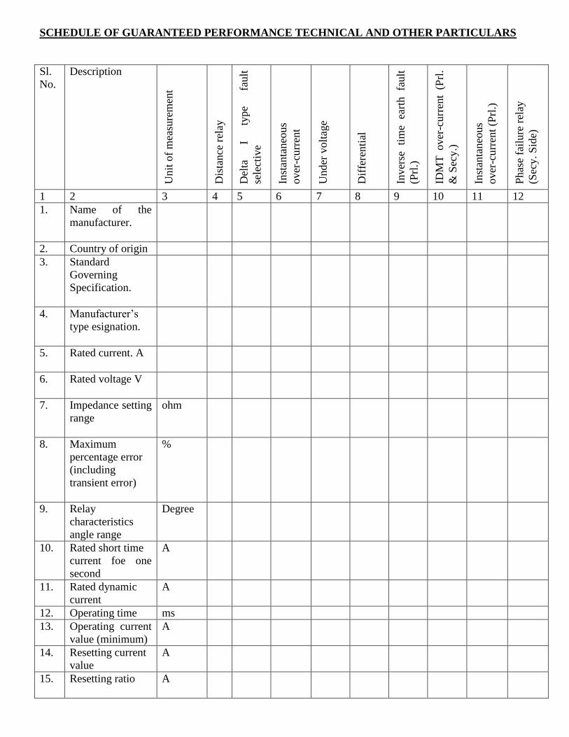
SCHEDULE OF GUARANTEED PERFORMANCE TECHNICAL AND OTHER PARTICULARS
Sl.
No.
Description
Unit
of
mea
sure
men
t
Dis
tance
rel
ay
Del
ta
I ty
pe
fault
sele
ctiv
e
Inst
anta
neo
us
over
-cu
rren
t
Under
volt
age
Dif
fere
nti
al
Inver
se
tim
e ea
rth
fault
(Prl
.)
IDM
T over
-curr
ent
(Prl
.
& S
ecy.)
Inst
anta
neo
us
over
-cu
rren
t (P
rl.)
Phas
e fa
ilure
rel
ay
(Sec
y. S
ide)
1 2 3 4 5 6 7 8 9 10 11 12
1. Name of the
manufacturer.
2. Country of origin
3. Standard
Governing
Specification.
4. Manufacturer‟s
type esignation.
5. Rated current. A
6. Rated voltage V
7. Impedance setting
range
ohm
8. Maximum
percentage error
(including
transient error)
%
9. Relay
characteristics
angle range
Degree
10. Rated short time
current foe one
second
A
11. Rated dynamic
current
A
12. Operating time ms
13. Operating current
value (minimum)
A
14. Resetting current
value
A
15. Resetting ratio A
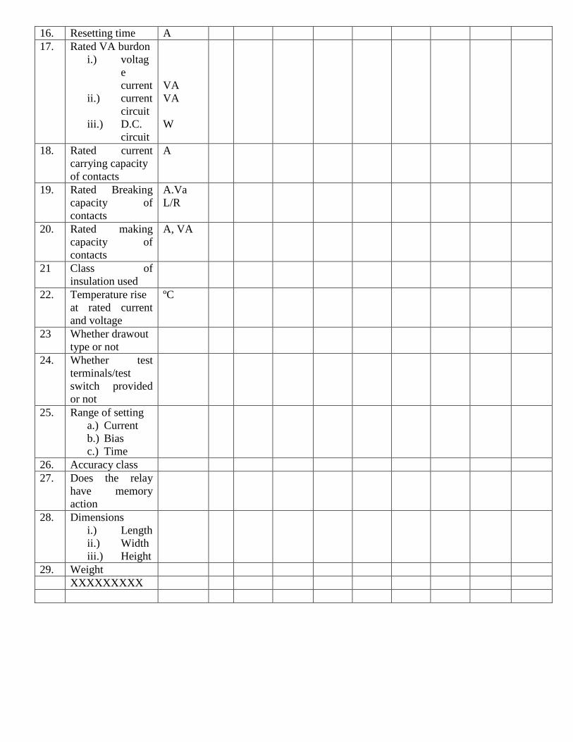
16. Resetting time A
17. Rated VA burdon
i.) voltag
e
current
ii.) current
circuit
iii.) D.C.
circuit
VA
VA
W
18. Rated current
carrying capacity
of contacts
A
19. Rated Breaking
capacity of
contacts
A.Va
L/R
20. Rated making
capacity of
contacts
A, VA
21 Class of
insulation used
22. Temperature rise
at rated current
and voltage
ºC
23 Whether drawout
type or not
24. Whether test
terminals/test
switch provided
or not
25. Range of setting
a.) Current
b.) Bias
c.) Time
26. Accuracy class
27. Does the relay
have memory
action
28. Dimensions
i.) Length
ii.) Width
iii.) Height
29. Weight
XXXXXXXXX