Embed Size (px)
Citation preview

Y:\201610\20161043\04_Design\Final\Bidding\Addendums\20180326_Addendum_No_3\20180321_Addendum_No_3.docx
Daniel W. Mitchell Nancy M.D. Faught Keith D. McCormack Jesse B. VanDeCreek
Roland N. Alix Michael C. MacDonald
James F. Burton Charles E. Hart
Donna M. Martin
Gary J. TresselRandal L. Ford
William R. Davis Dennis J. Benoit
Robert F. DeFrain Thomas D. LaCross Albert P. Mickalich Timothy H. Sullivan Thomas G. Maxwell
Marshall J. GrazioliColleen L. Hill-Stramsak
Bradley W. Shepler Karyn M. Stickel Jane M. Graham
Todd J. Sneathen Aaron A. Uranga
Salvatore Conigliaro Melissa A. Coatta Michael P. Darga
Brian K. Davies James E. Scholl
Matthew G. Slicker James J. Surhigh
Trevor S. Wagenmaker
ADDENDUM NO. 3 PROPOSED CEDAR ST DELHI CHARTER TOWNSHIP INGHAM COUNTY, MICHIGAN April 2, 2018 HRC Job No. 20161043 ONLINE ONLY http://www.hrcengr.com/bid-info/ INTENT: This Addendum No. 3 is issued prior to receipt of bids to provide for certain changes and clarifications to the specifications and/or the plans, as herein specified, and is hereby made a part of the Contract Documents and shall be taken into consideration in preparing the Proposal. The General Conditions and Specifications for the original work and the Contract Drawings are to govern this work unless otherwise revised herein. All other conditions remain the same. CONTRACT DOCUMENTS
1. SPECIFICATION SECTION 00030 – ADVERTISEMENT FOR BIDS
• Updated due date for Bids. 2. SPECIFICATION SECTION 00150 – PROPOSAL
• Updated due date for Bids
• Updated quantities for “Curb and Gutter Rem – Ft” pay item.
• Updated quantities for Sidewalk, Rem – Syd” pay item.
• Updated quantities for “Granular Material, Cl II, 10 inch – Cyd” pay item.
• Updated quantities for “Aggregate Base, 4 inch, CIP, 21AA – Syd” pay item.
• Updated quantities for “Aggregate Base, 6 inch, CIP, 21AA – Syd” pay item.
• Additional Pay Item and quantities for “Geosynthetic Paving Interlayer, Class I-560– Syd” pay item.
• Additional Pay Item and quantities for “Tack Coat, PG Asphalt– Ton” pay item.
• Updated quantities for “Dr Structure Cover, Adj, Case 1– Ea” pay item.
• Updated quantities for “Public Utility Structure Cover, Adj, Case I– Ea” pay item.
• Updated quantities for “Public Utility Structure Cover, Adj, Case II– Ea” pay item.
• Additional Pay Item and quantities for “Cold Milling HMA Surface, Modified– Syd” pay item.
• Additional Pay Item and quantities for “Surplus Material Delivery (Mason)” pay item.
• Additional Pay Item and quantities for “HMA Surface, Rem, Special” pay item.
• Updated quantities for “HMA, 4E1– Ton” pay item.
• Additional Pay Item quantities for “HMA, 5E03– Ton” pay item.
• Updated quantities for “HMA, Approach-Ton” pay item.
• Updated quantities for “Curb and Gutter, Conc, Det C4- Ft” pay item.

All Prospective Bidders April 2, 2018 HRC Job Number 20161043 Page 2 of 5
Y:\201610\20161043\04_Design\Final\Bidding\Addendums\20180326_Addendum_No_3\20180321_Addendum_No_3.docx
• Updated quantities for “Curb Ramp Opening, Conc - Ft” pay item.
• Updated quantities for “Sidewalk Ramp, Conc, 6 inch- Sft” pay item.
• Updated quantities for “Sidewalk, Conc, 4 inch- Sft” pay item.
• Updated quantities for “Detectable Warning Surface, Cast Iron- Ft” pay item.
• Updated quantities for “Pavt Mrkg, Ovly Cold Plastic, 12 inch, Crosswalk- Ft” pay item.
• Updated quantities for “Pavt Mrkg, Ovly Cold Plastic, 24 inch, Stop Bar- Ft” pay item.
• Updated quantities for “Pavt Mrkg, Ovly Cold Plastic, Lt Turn Arrow Sym- Ft” pay item.
• Updated quantities for “Pavt Mrkg, Ovly Cold Plastic, Only- Ft” pay item.
• Updated quantities for “Pavt Mrkg, Ovly Cold Plastic, Rt Turn Arrow Sym- Ft” pay item.
• Updated quantities for “Pavt Mrkg, Ovly Cold Plastic, Thru Arrow Sym- Ft” pay item.
• Updated quantities for “Pavt Mrkg, Sprayable Thermopl, 4 inch, White- Ft” pay item.
• Updated quantities for “Pavt Mrkg, Sprayable Thermopl, 4 inch, Yellow- Ft” pay item.
• Updated quantities for “Pavt Mrkg, Sprayable Thermopl, 4 inch, Yellow- Ft” pay item.
• Updated quantities for “Pushbutton, Rem- Ea” pay item.
• Updated quantities for “Pushbutton and Sign, Salv- Ea” pay item
• Updated quantities for “San Sewer, PVC SDR 26, 8 inch, CSB- Ft” pay item.
• Updated quantities for “San Sewer, PVC SDR 26, 10 inch, CSB- Ft” pay item.
3. SPECIFICATION SECTION 00500 AGREEMENT
• Updated completion and final payment date. 4. SPECIFICATION SECTION 00520 NOTICE TO PROCEED
• Updated completion and final payment date. 5. SPECIFICATIONS- PROGRESS CLAUSE
• Updated Progress schedule for additional work on Cedar St north of Aurelius Rd.
6. SPECIAL PROVISIONS
• Updated Maintaining Traffic provision for additional work on Cedar St north of Aurelius Rd.
• Additional Special Provision for “Geosynthetic Paving Interlayer, Class I-560” and “Tack Coat, PG Asphalt.”
• Additional Special Provision for “Cold Milling HMA Surface, Rem, Special”, “HMA Surface, Rem, Special”, and “Surplus Material Delivery, (Mason).”
• Additional Special Provision for “Recycled Hot Mix Asphalt Mixture on Local Agency Projects.”
7. MDOT MAINTAINING TRAFFIC TYPICALS
• Additional Maintaining Traffic Typical, “M0320a: Typical Temporary Traffic Control for Closing One-Half of a Four-Lane Undivided Roadway

All Prospective Bidders April 2, 2018 HRC Job Number 20161043 Page 3 of 5
Y:\201610\20161043\04_Design\Final\Bidding\Addendums\20180326_Addendum_No_3\20180321_Addendum_No_3.docx
Using a Reduced Speed Limit Where Workers Present in One Direction Only.”
• Additional Maintaining Traffic Typical, “M0350a: Typical Temporary Traffic Control for Closing a Center-Lane for Left Turn Only and an Adjacent Through Lane on a Multi-Lane Undivided Roadway Using a Single Step Down in Speed Limit in One Direction Only.”
• Additional Maintaining Traffic Typical, “M0350a: Typical Temporary Traffic Control for Closing a Center-Lane for Left Turn Only and an Adjacent Through Lane on a Multi-Lane Undivided Roadway Using a Single Step Down in Speed Limit in One Direction Only.”
• Additional Maintaining Traffic Typical, “M0380a: Typical Temporary Traffic Control for Closing a Center-Lane for Left Turn Only and an Adjacent Through Lane in Each Direction on a Multi-Lane Undivided Roadway Using a Single Step Down in Speed Limit.”
• Additional Maintaining Traffic Typical, “M0380a: Typical Temporary Traffic Control for Closing a Center-Lane for Left Turn Only and an Adjacent Through Lane in Each Direction on a Multi-Lane Undivided Roadway Using a Single Step Down in Speed Limit.”
• Additional Maintaining Traffic Typical, “M0410a: Typical Temporary Traffic Control for Closing One Lane of a Five-Lane Undivided Roadway and Maintaining Two Through Lanes in Each Direction Using a Single Step Down in Speed Limit in One Direction Only.”
• Additional Maintaining Traffic Typical, “M0440a: Typical Temporary Traffic Control for Closing Two Adjacent Through Lanes of a Five-Lane Undivided Roadway Using a Single Step Down in Speed Limit in One Direction Only.”
• Additional Maintaining Traffic Typical, “M0470a: Typical Temporary Traffic Control for Closing Two Adjacent Through Lanes of a Five-Lane Undivided Roadway Using a Single Step Down in Speed Limit.”
• Additional Maintaining Traffic Typical, “M0500a: Typical Temporary Traffic Control for Closing Three Lanes of a Five-Lane Undivided Roadway Using a Single Step Down in Speed Limit.”
CONTRACT DRAWINGS
1. Issued Drawings for additional work on Cedar St north of Aurelius Rd to Willoughby Rd.
2. Updated “General Provisions” on Cover Sheet (Sheet No. 1) 3. Additional Pay Item for “Stump, Rem, 6 inch to 18 inch” and “Stump, Rem, 19
inch to 36 inch.”
• Sheet No. 32
• Sheet No. 38
• Sheet No. 41
• Sheet No. 48 4. Updated Quantities for “Granular Material, Cl II, 10 inch – Cyd” pay item
• Sheet No. 30
• Sheet No. 33
• Sheet No. 36

All Prospective Bidders April 2, 2018 HRC Job Number 20161043 Page 4 of 5
Y:\201610\20161043\04_Design\Final\Bidding\Addendums\20180326_Addendum_No_3\20180321_Addendum_No_3.docx
• Sheet No. 39
• Sheet No. 42
• Sheet No. 44
• Sheet No. 46
• Sheet No. 48
• Sheet No. 49 5. Fixed incorrect Linetype for “Curb & Gutter, Rem – Ft”
• Sheet No. 29
• Sheet No.32
• Sheet No. 35
• Sheet No. 38
• Sheet No. 41
• Sheet No. 44
• Sheet No. 46
• Sheet No. 48 6. Increase Pipe Size of Sanitary Sewer at Sta 11+50 on Veterans Drive and
Updated Quantities for “San Sewer, PVC SDR 26, 8 inch, CSB” and “San Sewer, PVC SDR 26, 10 inch, CSB.”
• Sheet No. 52 7. Added additional “Pushbutton, Rem” pay item quantities on Cedar St and Holt
Rd Intersection
• Sheet No. 74 8. Additional Pay Item “Pushbutton and Sign, Slav” for the intersection of Cedar St
and Holt Rd.
• Sheet No. 75 9. Removed Alternate callout for Alternate #1 since it’s not applicable.
• Sheet No. 110

All Prospective Bidders April 2, 2018 HRC Job Number 20161043 Page 5 of 5
Y:\201610\20161043\04_Design\Final\Bidding\Addendums\20180326_Addendum_No_3\20180321_Addendum_No_3.docx
A copy of the amended pages of the Contract Documents and Drawings noted in this Addendum No. 3 have been posted online at http://www.hrcengr.com/bid-info/ and should be utilized during the preparation of the bids and incorporated into the Bid Documents. The Contractor shall acknowledge receipt of this Addendum No. 3 by signing in the location provided below and incorporating this Addendum No. 3 with the submission of this bid. Failure to include Addendum No. 3 and its attachments may result in rejection of the bid If you have any questions or require any additional information, please contact the undersigned. Very truly yours, HUBBELL, ROTH & CLARK, INC.
Lia Michaels LFM/lfm Attachment pc: All Prospective Bidders Delhi Charter Township; Tracy Miller, Lori Underhill, Howard Haas HRC; J. Burton, T. Sneathen, C. Butler Accepted by: Company Name: ______________________________________________________ Name: ______________________________________________________________ Written Name: ________________________________________________________ Address: ____________________________________________________________ Telephone: ______________________________Fax: _________________________

DELHI TOWNSHIP ADVERTISEMENT FOR BIDS PROPOSED CEDAR ST 00030 / 1
Hubbell, Roth & Clark, Inc. Job 20161043
y:\201610\20161043\04_design\final\bidding\addendums\20180326_addendum_no_3\00030_advertisement_r20091006_add_no_3.
ADVERTISEMENT FOR BIDS PROPOSED CEDAR ST
DELHI CHARTER TOWNSHIP INGHAM COUNTY, MICHIGAN
Sealed proposals for the construction of the Proposed Cedar St Project will be received by Delhi Charter Township at the Township Hall located at 2074 Aurelius Road, Holt MI 48842 until 2:00 p.m., Local Time on Friday, April 13, 2018, at which time and place all bids will be publicly opened and read. Bidders shall review and comply with the Instructions to Bidders, which are incorporated by reference, and carefully review all Contract Documents, as defined in the Instructions to Bidders. Bids submitted after the exact time specified for, receipt will not be considered. The Contracts will consist of the following principal items of work and appurtenances as specified herein and shown on the Contract Drawings. Description of Work Full depth street reconstruction of 0.75 miles and new HMA pavement, concrete curb and gutter, storm sewer, sanitary sewer, sidewalks, ADA sidewalk ramps, permanent pavement markings, signs, signal upgrades, street lighting and landscaping. Paper Copies of Plans and Specifications and Proposal Forms shall be available on or after 10:00 AM March 5th, 2018 at the offices of Hubbell, Roth & Clark, Inc., Consulting Engineers, 555 Hulet Drive, Bloomfield Hills, Michigan 48302-0360. A non-refundable payment of Two Hundred ($200.00) Dollars, CHECK ONLY, payable to “Hubbell, Roth & Clark, Inc.” will be required for each set of Drawings and Specifications. Drawings and Specifications can be shipped by U.P.S. ground for a shipping and handling charge of Forty-Five ($45.00) Dollars, CHECK ONLY, non-refundable, to Hubbell, Roth & Clark, Inc. The Bidder is advised that to submit a bid on this project, the Bidder must have purchased a set of Plans and Specifications from Hubbell, Roth & Clark, Inc. Questions regarding this project should be addressed to the Project Manager: Lia Michaels, via email at: [email protected]. Proposals submitted by Bidders who have been debarred, suspended, or made ineligible by any Federal Agency will be rejected. Each bidder agrees to waive any claim it has or may have against the Owner, the Architect/Engineer, and their respective employees, arising out of or in connection with the administration, evaluation, or recommendation of any bid. The successful bidder will be required to furnish satisfactory Performance, Labor and Material, and Maintenance and Guarantee Bonds. Delhi Charter Township reserves the right to reject all bids and to waive irregularities in bidding.

DELHI TOWNSHIP ADVERTISEMENT FOR BIDS PROPOSED CEDAR ST 00030 / 2
Hubbell, Roth & Clark, Inc. Job 20161043
y:\201610\20161043\04_design\final\bidding\addendums\20180326_addendum_no_3\00030_advertisement_r20091006_add_no_3.
No Proposal will be received unless made on blanks furnished and delivered to the Delhi Charter Township Clerk on or before 2:00 p.m., Local time, April 13th, 2018. DELHI CHARTER TOWNSHIP

DELHI CHARTER TOWNSHIP PROPOSAL PROPOSED CEDAR ST 00150 / 1
Hubbell, Roth & Clark, Inc. Job 20161043
y:\201610\20161043\04_design\final\bidding\addendums\20180326_addendum_no_3\00150_proposal_r20100629_add_no_3.docx 0
PROPOSAL FOR
PROPOSED CEDAR ST DELHI CHARTER TOWNSHIP
INGHAM COUNTY, MICHIGAN
Delhi Charter Township Bids Due: April 13, 2018 2074 Aurelius Road On or Before 2:00 pm, Local Time Holt, Michigan 48842 HRC Job No. 20161043 To Prospective Bidders: Name of Bidder: Address: Date: Telephone: Fax:
The above, as Bidder, hereby declares this bid is made in good faith without fraud or collusion with any persons bidding, and that the Drawings, Specifications, and all other information referenced in the Instructions to Bidders have been examined. Further, the Bidder is familiar with the location of the work described herein and is fully informed as to the nature of the work and the conditions relating to the performance of the Contract. The Bidder acknowledges that no representations or warranties of any nature whatsoever have been received, or are relied upon from the Charter Township of Delhi, its agents or employees, as to any conditions to be encountered in accomplishing the work and that the bid is based solely upon the Bidder’s own independent judgment. The above, as Bidder, hereby certifies that the Drawings, Specifications, and other data provided by the Owner for bidding purposes have been examined. Further, the undersigned certifies that the proposed construction methods have been reviewed and found acceptable for the conditions which can be anticipated from the information provided for bidding. The Bidder hereby affirms that the site of work has been inspected and further declares that no charges in addition to the Individual Unit Prices shall be made on account of any job circumstances or field conditions which were present and/or ascertainable prior to the bidding. In addition, The Contractor, as such and as Bidder, shall make the determination as to existing soil conditions and shall also complete the work under whatever conditions created by the Contractor/Bidder’s sequence of construction, construction methods, or other conditions the Contractor/Bidder may create, at no additional cost to the Owner. The above, as Bidder, confirms knowledge of the location of the Proposed Cedar St Project and appurtenant construction in the Charter Township of Delhi, Ingham County, Michigan, and the conditions under which it must be constructed; and also declares to have carefully examined the Drawings, Specifications, and Contract Documents which the Bidder understands and accepts as sufficient for the purpose of constructing said Proposed Cedar St Project, and appurtenant work, and agrees to contract with the Charter Township of Delhi to furnish all labor, materials, tools, equipment, facilities and supervision necessary to do all the work specified and prescribed for the Charter Township of Delhi, in strict accordance with the Owner’s General Conditions, and with the full

DELHI CHARTER TOWNSHIP PROPOSAL PROPOSED CEDAR ST 00150 / 2
Hubbell, Roth & Clark, Inc. Job 20161043
y:\201610\20161043\04_design\final\bidding\addendums\20180326_addendum_no_3\00150_proposal_r20100629_add_no_3.docx 0
intent of the Drawings and Specifications, prepared by Hubbell, Roth & Clark, Consulting Engineers, and will accept in full payment therefore the sum of: BASE BID Item Quantity Unit Price Total Cost 1. Mobilization, (Max 10%) 1 Lsum @ $ = $ 2. Stump, Rem, 6 inch to 18 inch 6 Ea @ $ = $ 3. Stump, Rem, 19 inch to 36 inch 6 Ea @ $ = $ 4. Dr Structure, Rem 33 Ea @ $ = $ 5. Sewer, Rem, Less than 24 inch 1802 Ft @ $ = $ 6. Gas Main, Rem 2000 Ft @ $ = $ 7. Curb and Gutter, Rem 8255 Ft @ $ = $ 8. Pavt, Rem 20288 Syd@ $ = $ 9. Sidewalk, Rem 3327 Syd @ $ = $ 10. Exploratory Investigation, Vertical 200 Ff @ $ = $ 11. Embankment, CIP 1989 Cyd @ $ = $ 12. Excavation, Earth 13334 Cyd@ $ = $ 13. Granular Material, Cl II, 10 inch 7048 Cyd @ $ = $ 14. Non Haz Contaminated Material Handling and
Disposal, LM 333 Cyd @ $ = $ 15. Erosion Control, Inlet Protection, Fabric Drop 72 Ea @ $ = $ 16. Erosion Control, Silt Fence 200 Ff @ $ = $ 17. Project Cleanup 1 Lsum @ $ = $ 18. Aggregate Base, 4 inch, CIP, 21AA 4915 Syd @ $ = $ 19. Aggregate Base, 6 inch, CIP, 21AA 2550 Syd @ $ = $ 20. Aggregate Base, 8 inch, CIP, 21AA 24744 Syd @ $ = $ 21. Geotextile, Special 20035 Syd @ $ = $ 22. Geosynthetic Paving Interlayer, Class I-560 27828 Syd @ $ = $ 23. Tack Coat, PG Asphalt 47 Ton @ $ = $ 24. Subgrade Undercutting, 1 x 3 1000 Cyd @ $ = $ 25. Maintenance Gravel 2000 Ton @ $ = $ 26. Shoulder, Cl I 2 Ton @ $ = $ 27. Sewer, Cl IV, 12 inch, Tr Det B 2637 Ft @ $ = $ 28. Sewer Tap, 12 inch 10 Ea @ $ = $ 29. Sewer Tap, 15 inch 4 Ea @ $ = $ 30. Sewer Bulkhead, 12 inch 11 Ea @ $ = $ 31. Sewer Bulkhead, 15 inch 2 Ea @ $ = $ 32. Trench Undercut and Backfill 100 Cyd@ $ = $ 33. Video Taping Sewer and Culv Pipe 2637 Ft @ $ = $ 34. San Sewer Lead, PVC SDR 23.5, 6 inch, CSB 189 Ft @ $ = $ 35. Sewer Bulkhead, 10 inch or less 27 Ea @ $ = $ 36. Sump Pump Lead and Drain Tile Connection 105 Ft @ $ = $ 37. Dr Structure Cover, Adj, Case 1 29 Ea @ $ = $ 38. Dr Structure Cover, Adj, Case 2 4 Ea @ $ = $ 39. Dr Structure Cover, Type B 14 Ea @ $ = $ 40. San Manhole Cover, Special 4 Ea @ $ = $ 41. Dr Structure Cover, Type G 4 Ea @ $ = $ 42. Dr Structure Cover ,Type K 48 Ea @ $ = $

DELHI CHARTER TOWNSHIP PROPOSAL PROPOSED CEDAR ST 00150 / 3
Hubbell, Roth & Clark, Inc. Job 20161043
y:\201610\20161043\04_design\final\bidding\addendums\20180326_addendum_no_3\00150_proposal_r20100629_add_no_3.docx 0
43. Dr Structure Lead, Cleaning, 6 inch 100 Ft @ $ = $ 44. Dr Structure Lead, Cleaning, 12 inch 120 Ft @ $ = $ 45. Dr Structure Lead, Cleaning, 15 inch 80 Ft @ $ = $ 46. Dr Structure, 24 inch dia 35 Ea @ $ = $ 47. Dr Structure, 48 inch dia 25 Ea @ $ = $ 48. Dr Structure, 60 inch dia 1 Ea @ $ = $ 49. Dr Structure, Add Depth of 48 inch dia,
8 foot to 15 foot 8 Ft @ $ = $ 50. Dr Structure, Adj, Add Depth 26 Ft @ $ = $ 51. Dr Structure, Cleaning 33 Ea @ $ = $ 52. Dr Structure, Tap, 6 inch 9 Ea @ $ = $ 53. San Manhole Tap 10 inch 2 Ea @ $ = $ 54. Dr Structure, Tap, 12 inch 12 Ea @ $ = $ 55. Public Utility Structure, Adj, Add Depth 11 Ft @ $ = $ 56. Public Utility Structure Cover, Adj, Case I 37 Ea @ $ = $ 57. Public Utility Structure Cover, Adj, Case II 5 Ea $ = $ 58. Underdrain, Subgrade, Open-Graded, 6 inch 8268 Ft @ $ = $ 59. Cold Milling HMA Surface, Modified 27828 Syd @ $ = $ 60. Surplus Material Delivery, (Mason) 2706 Cyd @ $ = $ 61. HMA Surface, Rem 23739 Syd @ $ = $ 62. HMA Surface, Rem, Special 25 Syd @ $ = $ 63. Hand Patching 335 Ton @ $ = $ 64. HMA, 3C 3885 Ton @ $ = $ 65. HMA, 4E1 8618 Ton @ $ = $ 66. HMA, 5E03 1531 Ton @ $ = $ 67. HMA Approach 187 Ton @ $ = $ 68. HMA Approach (Commercial) 153 Ton @ $ = $ 69. Conc Pavt with Integral Curb, Nonreinf, 8 inch 1243 Syd @ $ = $ 70. Driveway, Nonreinf, Concrete, 6 inch 593 Syd @ $ = $ 71. Curb, Conc, Det E2 76 Ft @ $ = $ 72. Curb and Gutter, Conc, Det C4 8059 Ft @ $ = $ 73. Curb and Gutter, Conc, Det F4 18 Ft @ $ = $ 74. Driveway Opening, Conc, Det M 1676 Ft @ $ = $ 75. Spillway, Conc 7 Ft @ $ = $ 76. Curb Ramp Opening, Conc 349 Ft @ $ = $ 77. Sidewalk Ramp, Conc, 6 inch 2646 Sft @ $ = $ 78. Sidewalk, Conc, 4 inch 36116 Sft @ $ = $ 79. Sidewalk Conc, 6 inch 2865 Sft @ $ = $ 80. Detectable Warning Surface, Cast Iron 322 Ft @ $ = $ 81. Post, Mailbox 2 Ea @ $ = $ 82. Post, Steel, 3 lb 561 Ft @ $ = $ 83. Sign, Type III, Rem 62 Ea @ $ = $ 84. Sign, Type IIIA 134 Sft @ $ = $ 85. Sign, Type IIIB 245 Sft @ $ = $ 86. Mast Arm Pole, Cat III 9 Ea @ $ = $ 87. Mast Arm 25 foot, Cat III 1 Ea @ $ = $ 88. Mast Arm, 35 foot, Cat III 1 Ea @ $ = $ 89. Mast Arm, 40 foot, Cat III 2 Ea @ $ = $ 90. Mast Arm, 45 foot, Cat III 2 Ea @ $ = $ 91. Mast Arm, 50 foot, Cat III 3 Ea @ $ = $

DELHI CHARTER TOWNSHIP PROPOSAL PROPOSED CEDAR ST 00150 / 4
Hubbell, Roth & Clark, Inc. Job 20161043
y:\201610\20161043\04_design\final\bidding\addendums\20180326_addendum_no_3\00150_proposal_r20100629_add_no_3.docx 0
92. Mast Arm Pole Fdn, 6 Bolt 126 Ft @ $ = $ 93. Mast Arm, Rem 11 Ea @ $ = $ 94. Pavt Mrkg, Ovly Cold Plastic, 12 inch, Cross
Hatching, White 180 Ft @ $ = $ 95. Pavt Mrkg, Ovly Cold Plastic, 12 inch, Cross
Hatching, Yellow 120 Ea @ $ = $ 96. Pavt Mrkg, Ovly Cold Plastic, 12 inch, Crosswalk 1728 Ft @ $ = $ 97. Pavt Mrkg, Ovly Cold Plastic, 24 inch, Stop Bar 460 Ft @ $ = $ 98. Pavt Mrkg, Ovly Cold Plastic, Direction Arrow
Sym, Bike 26 Ea @ $ = $ 99. Pavt Mrkg, Ovly Cold Plastic, Bike, Small Sym 26 Ea @ $ = $ 100. Pavt Mrkg, Ovly Cold Plastic, Lt Turn Arrow Sym 13 Ea @ $ = $ 101. Pavt Mrkg, Ovly Cold Plastic, Only 20 Ea @ $ = $ 102. Pavt Mrkg, Ovly Cold Plastic, Rt Turn Arrow Sym 9 Ea @ $ = $ 103. Pavt Mrkg, Ovly Cold Plastic, Thru and Lt Turn
Arrow Sym 1 Ea @ $ = $ 104. Pavt Mrkg, Ovly Cold Plastic, Thru and Rt Turn
Arrow Sym 3 Ea @ $ = $ 105. Pavt Mrkg, Ovly Cold Plastic, Thru Arrow Sym 4 Ea @ $ = $ 106. Pavt Mrkg, Sprayable Thermopl, 4 inch, White 13560 Ft @ $ = $ 107. Pavt Mrkg, Sprayable Thermopl, 4 inch Yellow 22865 Ft @ $ = $ 108. Rem Spec Mrkg 126 Sft @ $ = $ 109. Pavt Mrkg, Wet Reflective, Type R Tape,
4 inch, Yellow, Temp 9000 Ea @ $ = $ 110. Pavt Mrkg, Wet Reflective, Type NR, Paint,
4 inch, Yellow Temp 1000 Ft@ $ = $ 111. Barricade, Type III, High Intensity, Lighted, Furn 23 Ea @ $ = $ 112. Barricade, Type III, High Intensity, Lighted, Oper 23 Ea @ $ = $ 113. Channelizing Device, 42 inch, Furn 100 Ea @ $ = $ 114. Channelizing Device, 42 inch, Oper 100 Ea @ $ = $ 115. Lighted Arrow, Type C, Furn 3 Ea @ $ = $ 116. Lighted Arrow, Type C, Oper 3 Ea @ $ = $ 117. Minor Traf Devices 1 Lsum @ $ = $ 118. Pavt Mrkg, Longit, 6 inch or Less Width, Rem 4350 Ft @ $ = $ 119. Pavt Mrkg, Longit, Greater than 6 inch Width, Rem 100 Ft @ $ = $ 120. Pavt Mrkg, Wet Reflective, Type NR, Paint,
4 inch, White, Temp 5200 Ft @ $ = $ 121. Pavt Mrkg, Wet Reflective, Type R, Tape,
4 inch, White , Temp 2000 Ft @ $ = $ 122. Plastic Drum, High Intensity, Furn 270 Ea @ $ = $ 123. Plastic Drum, High Intensity, Oper 270 Ea @ $ = $ 124. Sign Cover 100 Ea @ $ = $ 125. Sign, Portable, Changeable Message, Furn 2 Ea @ $ = $ 126. Sign, Portable, Changeable Message, Oper 2 Ea @ $ = $ 127. Sign, Type A, Temp, Prismatic, Furn 200 Sft @ $ = $ 128. Sign, Type A, Temp, Prismatic, Oper 200 Sft @ $ = $ 129. Sign, Type B, Temp Prismatic, Furn 1500 Sft @ $ = $ 130. Sign, Type B, Temp Prismatic, Oper 1500 Sft @ $ = $ 131. Sign, Type B, Temp Prismatic, Special Furn 700 Sft @ $ = $ 132. Sign, Type B, Temp Prismatic, Special Oper 700 Sft @ $ = $

DELHI CHARTER TOWNSHIP PROPOSAL PROPOSED CEDAR ST 00150 / 5
Hubbell, Roth & Clark, Inc. Job 20161043
y:\201610\20161043\04_design\final\bidding\addendums\20180326_addendum_no_3\00150_proposal_r20100629_add_no_3.docx 0
133. Traf Regulator Control 1 Lsum @ $ = $ 134. Pedestrian Type II Barricade, Temp 10 Ea @ $ = $ 135. Turf Establishment 2700 Syd @ $ = $ 136. Bioretention Swale 1 Lsum @ $ = $ 137. Conduit, DB, 1, 1 1/2 inch 220 Ft @ $ = $ 138. Conduit, DB, 1, 3 inch 380 Ft @ $ = $ 139. Conduit, DB, 3, 3 inch 85 Ft @ $ = $ 140. Conduit, DB, 4, 3 inch 30 Ft @ $ = $ 141. Conduit, Rem 765 Ft @ $ = $ 142. Conduit, Schedule 40, 1 inch 4410 Ft @ $ = $ 143. Conduit, Schedule 40, 1 1/2 inch 60 Ft @ $ = $ 144. Conduit, Schedule 40, 2 inch 3970 Ft @ $ = $ 145. Conduit, Schedule 40, 4 inch 2500 Ft @ $ = $ 146. Db Cable, In Conduit, 600V, 1/C #10 8805 Ft @ $ = $ 147. Db Cable, In Conduit, 600V, 1/C #2 6635 Ft @ $ = $ 148. Db Cable, In Conduit, 600V, 1/C #4 35635 Ft @ $ = $ 149. Db Cable, In Conduit, 600V, 1/C #6 3300 Ft @ $ = $ 150. Db Cable, In Conduit, 600V, 1/C #8 1180 Ft @ $ = $ 151. Db Cable, In Conduit, Rem 3110 Ft @ $ = $ 152. Cable, Equipment Grounding Wire, 1/C #1 1170 Ft @ $ = $ 153. Cable, Equipment Grounding Wire, 1/C #2 2145 Ft @ $ = $ 154. Cable, Equipment Grounding Wire, 1/C #4 4065 Ft @ $ = $ 155. Cable, Equipment Grounding Wire, 1/C #6 475 Ft @ $ = $ 156. Cable, Equipment Grounding Wire, 1/C #10 4400 Ft @ $ = $ 157. Hh, Polymer Conc 43 Ea @ $ = $ 158. Hh, Polymer Conc, Install Salv 8 Ea @ $ = $ 159. Hh, Rem and Salv 9 Ea @ $ = $ 160. Light Std Fdn 7 Ea @ $ = $ 161. Light Std Fdn, Rem 19 Ea @ $ = $ 162. Light Std Shaft 2 Ea @ $ = $ 163. Light Std Shaft, Install Salv 17 Ea @ $ = $ 164. Light Std Shaft, Rem and Salv 19 Ea @ $ = $ 165. Luminaire 58 Ea @ $ = $ 166. Luminaire, Install Salv 7 Ea @ $ = $ 167. Luminaire, Rem and Salv 57 Ea @ $ = $ 168. Cable, Sec, 600V, 1, 3/C#6 450 Ft @ $ = $ 169. Wood Pole, Fit Up, Sec, Cable Pole 2 Ea @ $ = $ 170. Conduit, Directional Bore, 1, 3 inch 350 Ft @ $ = $ 171. Conduit, Rigid Galv Steel, 1 inch 600 Ft @ $ = $ 172. Case Sign, Rem 17 Ea @ $ = $ 173. Case Sign (LED), One Way, 24 inch by 30 inch 3 Ea @ $ = $ 174. Controller and Cabinet, Rem 2 Ea @ $ = $ 175. Controller and Cabinet, Digital Type 2 Ea @ $ = $ 176. Controller Fdn, Base Mount 2 Ea @ $ = $ 177. Controller Fdn, Rem 2 Ea @ $ = $ 178. Global Positioning System Module 2 Ea @ $ = $ 179. Fdn, Rem 12 Ea @ $ = $ 180. Pedestal, Alum 16 Ea @ $ = $ 181. Pedestal, Fdn 21 Ea @ $ = $ 182. Pedestal Fdn, Rem 6 Ea @ $ = $

DELHI CHARTER TOWNSHIP PROPOSAL PROPOSED CEDAR ST 00150 / 6
Hubbell, Roth & Clark, Inc. Job 20161043
y:\201610\20161043\04_design\final\bidding\addendums\20180326_addendum_no_3\00150_proposal_r20100629_add_no_3.docx 0
183. Pedestal, Rem 2 Ea @ $ = $ 184. Pushbutton and Sign 25 Ea @ $ = $ 185. Pushbutton, Rem 19 Ea @ $ = $ 186. Pushbutton and Sign, Salv 3 Ea @ $ = $ 187. Pushbutton Pedestal, Alum 5 Ea @ $ = $ 188. Pushbutton Pedestal, Rem 2 Ea @ $ = $ 189. Service Disconnect 2 Ea @ $ = $ 190. TS, Mast Arm Mtd, Rem 20 Ea @ $ = $ 191. TS, Pedestrian, Bracket Arm Mtd, Rem 9 Ea @ $ = $ 192. TS, Pedestrian, Pedestal Mtd, Rem 2 Ea @ $ = $ 193. Cabinet, Rem 1 Ea @ $ = $ 194. TS, One Way Mast Arm Mtd, FYA (LED) 6 Ea @ $ = $ 195. TS, 4th Level, LTGA (LED) 2 Ea @ $ = $ 196. TS, Pedestrian, Two Way Bracket Arm Mtd
(LED) Countdown 3 Ea @ $ = $ 197. TS, Pedestrian, One Way Bracket Arm Mtd
(LED) Countdown 4 Ea @ $ = $ 198. TS, Pedestrian, One Way Pedestal Mtd
(LED) Countdown 4 Ea @ $ = $ 199. TS, Pedestrian, Two Way Pedestal Mtd
(LED) Countdown 1 Ea @ $ = $ 200. TS, One Way Mast Arm Mtd (LED) 16 Ea @ $ = $ 201. Sign Optical, Rem 4 Ea @ $ = $ 202. Video Traf Detection Camera, Rem 4 Ea @ $ = $ 203. Emergency Pre-emption, Rem 5 Ea @ $ = $ 204. Wireless Vehicle Detection System 2 Ea @ $ = $ 205. Wireless Vehicle Detection System, Rem 1 Ea @ $ = $ 206. Wireless Vehicle Sensor Node 37 Ea @ $ = $ 207. Wireless Vehicle Sensor Node, Rem 18 Ea @ $ = $ 208. TS, Bag 13 Ea @ $ = $ 209. TS, Bag, Rem 13 Ea @ $ = $ 210. TS Head, Temp 1 Ea @ $ = $ 211. Casing 95 Ft @ $ = $ 212. Backplate, TS 22 Ea @ $ = $ 213. Optical Priority Control System 2 Ea @ $ = $ 214. St Name Sign, Two Way, (LED), 6 foot 6 Ea @ $ = $ 215. St Name Sign, Two Way, (LED), 8 foot 2 Ea @ $ = $ 216. Tremie Pour 9 Ea @ $ = $ 217. Hydrant, Relocate, Case 1 5 Ea @ $ = $ 218. Water Shutoff, Adj, Case 1 49 Ea @ $ = $ 219. Water Shutoff, Adj, Case 2 22 Ea @ $ = $ 220. Sprinkler, Line 600 Ft @ $ = $ 221. Sprinkler Head, Relocate 30 Ea @ $ = $ 222. Sprinkler Head, Replace 30 Ea @ $ = $ 223. Hydrant, Adjust 2 Ea @ $ = $ 224. Water Main Crossing, Replacement 6 Ea @ $ = $ 225. Bollard, Steel, 8 inch, Special 5 Ea @ $ = $ 226. Color Audio Video Route Survey 1 Lsum @ $ = $ 227. Reimbursed Permit Fees 8000 Dlr @ $ = $ 228. San Manhole, Rem 5 Ea @ $ = $

DELHI CHARTER TOWNSHIP PROPOSAL PROPOSED CEDAR ST 00150 / 7
Hubbell, Roth & Clark, Inc. Job 20161043
y:\201610\20161043\04_design\final\bidding\addendums\20180326_addendum_no_3\00150_proposal_r20100629_add_no_3.docx 0
229. Sewer, Abandon 867 Ft @ $ = $ 230. San Sewer, PVC SDR 26, 8 inch, CSB 32 Ft @ $ = $ 231. San Sewer, PVC SDR 26, 10 inch, CSB 902 Ft @ $ = $ 232. San Service Connection, 6 inch 9 Ea @ $ = $ 233. San Service Clean Out, Double Wye, 6 inch 9 Ea @ $ = $ 234. Sanitary Manhole, 48 inch dia, Construct Over
Ex Sewer 1 Ea @ $ = $ 235. Sanitary Manhole, 48 inch dia 5 Ea @ $ = $ 236. San Manhole, Reconst 16 Ft @ $ = $ 237. Remove and Reinstall Pavers, Special 759 Sft @ $ = $ 238. Receptacle Pedestal 67 Ea @ $ = $ 239. Lighting Panel 1 Ea @ $ = $ 240. Lighting Control Enclosure 1 Ea @ $ = $ 241. Electrical Work 1 Lsum @ $ = $ 242. Perimeter Lit Flashing LED Sign Assembly 12 Ea @ $ = $ 243. Sidewalk, Conc, Exposed Aggregate, 6 inch 1329 Sft @ $ = $ 244. Sidewalk Ramp, Exposed Aggregate 991 Sft @ $ = $ 245. Fine Grade and Sodded lawn 4655 Syd @ $ = $ 246. Plant mix 140 Cyd @ $ = $ 247. Import Sandy Loam Topsoil
(incl. Supply, Install and Shaping) 425 Cyd @ $ = $ 248. Shredded Hardwood Bark Mulch 50 Cyd @ $ = $ 249. Aluminum edging (“Permaloc” 3/16”x4”,
or appv’d eq.) 385 Ft @ $ = $ 250. Plainwell Bench – 72”, Aluminum Seat,
Powder Coated Surface Mount 24 Ea @ $ = $ 251. Plainwell Litter Receptacle – Aluminum
Side Panel, 35 gal. Powder Coated, Surface Mount 13 Ea @ $ = $ 252. Sorella Planter – 30” x 30” x 30”,
Powder Coated Steel 25 Ea @ $ = $ 253. Ring Bike Rack – Embedded, Powder Coated 9 Ea @ $ = $ 254. Gleditsia t. ‘Skyline’, Skyline Honeylocust, 2.5” cal. 11 Ea @ $ = $ 255. Liriodendron tulipfera, Tulip Tree, 2.5” cal 31 Ea @ $ = $ 256. Quercus bicolor, Swamp White Oak, 2.5” cal. 37 Ea @ $ = $ 257. Ulmus a. ‘Valley Forge’, Valley Forge
Elm, 2.5” cal. 40 Ea @ $ = $ 258. Picea glauca, White Spruce, 23’-25’ ht., spaded 1 Ea @ $ = $ 259. Ilex g. ‘Nordic’, Nordic Inkberry Holy, 24” ht. 86 Ea @ $ = $ 260. Taxus x m. ‘Densiformis’, Dense Yew 30” ht. 49 Ea @ $ = $ 261. Physocarpus o. ‘Summer Wine’, Summer Wine
Ninebark 36” ht. 14 Ea @ $ = $ 262. Echinacea p. ‘Magnus’, Magnus Purple
Coneflower, 1 gal. 70 Ea @ $ = $ 263. Liriope m. ‘Big Blue’, Big Blue Liriope, 1 gal. 751 Ea @ $ = $ 264. Miscanthus s. ‘Morning Light’, Morning Light
Silver Grass, 3 gal. 10 Ea @ $ = $ 265. Nepeta f. ‘Walker’s Low’, Walker’s Low
Catmint, 1 gal. 62 Ea @ $ = $ 266. Pennisetum a. ‘Virdescens’, Virdescens
Dwarf Fountain Grass, 2 gal. 101 Ea @ $ = $

DELHI CHARTER TOWNSHIP PROPOSAL PROPOSED CEDAR ST 00150 / 8
Hubbell, Roth & Clark, Inc. Job 20161043
y:\201610\20161043\04_design\final\bidding\addendums\20180326_addendum_no_3\00150_proposal_r20100629_add_no_3.docx 0
267. Pannicum v. ‘North Wind’, North Wind Switchgrass, 2 gal. 52 Ea @ $ = $
268. Rudbeckia f. ‘Goldstrum’, Goldstrum Black-eyed Susan, 1 gal. 356 Ea @ $ = $
269. Sedum s. ‘Matrona’, Matrona Sedum, 1 gal. 54 Ea @ $ = $ 270. Masonry Gateway Signs complete,
(include concrete footing, minimum 42” depth) 2 Ea @ $ = $ 271. Masonry Gateway Placards complete,
(include concrete footing, minimum 42” depth) 2 Ea @ $ = $ 272. 36” height Masonry Piers complete,
(include concrete footing, minimum 42” depth) 2 Ea @ $ = $ 273. 30” height Masonry Wall complete,
(include concrete footing, minimum 42” depth) 40 Ft @ $ = $ 274. 6” Concrete Planter Curb, complete 120 Ft @ $ = $ 275. Irrigation System, Special 1 Lsum @ $ = $ Total Amount of Bid $ ___________ ALTERNATES Voluntary Alternates proposed by the Bidder will not be considered. The Bidder shall submit a bid based on the information shown on the Drawings and Specifications. Alternates listed below are for the Owner’s convenience and shall be priced as indicated by the work description. All alternates shall be clearly marked whether they represent an add or deduct to the Base Bid Price quoted herein. All Alternates which are quoted shall be complete and the price shall include all Bidder mark-ups. Each Alternate shall be clearly marked if it represents an Add or a Deduct from the Base Bid Price. The Owner reserves the right to award the Base Bid depending upon the availability of funds. The Owner, at its sole discretion, reserves the right to award to the Bidder who, in the sole determination of the Owner, will best serve the interest of the Owner. The Owner reserves the right to accept any bid, to reject any or all bids, to waive any and all informalities involving price, time, or changes in the work, and to negotiate contract terms with the successful Bidder, and the right to disregard all nonconforming, nonresponsive, unbalanced or conditional bids. However, it is the intention of the Owner to award to the low total bid to one bidder. Also, the Owner reserves the right to reject the bid of any Bidder if the Owner believes that it would not be in the best interest of the Project to make an award to that Bidder, whether because the bid is not responsive or the Bidder is unqualified, of doubtful financial ability, or fails to meet any other pertinent standard or criteria established by the Owner. Each bidder agrees to waive any claim it has or may have against the Owner, the Architect/Engineer, and their respective employees, arising out of or in connection with the administration, evaluation, or recommendation of any bid. TAXES The Bidder affirms that all applicable Federal, State and Local taxes of whatever character and description are included in all prices stated in this Form of Proposal. ADDENDA

DELHI CHARTER TOWNSHIP PROPOSAL PROPOSED CEDAR ST 00150 / 9
Hubbell, Roth & Clark, Inc. Job 20161043
y:\201610\20161043\04_design\final\bidding\addendums\20180326_addendum_no_3\00150_proposal_r20100629_add_no_3.docx 0
The Bidder acknowledges the following Addenda, covering revisions to the drawings or specifications and the cost, if any, of such revision has been included in the quoted proposal: Addendum No. ___________________________ Dated _______________________
Addendum No. ___________________________ Dated _______________________
Addendum No. ___________________________ Dated _______________________
Addendum No. ___________________________ Dated _______________________
FEES The Bidder shall refer to the General Conditions for allowable Fees for additional work performed, upon Owner’s written authorization, by Bidder’s own forces and/or for additional work, upon Owner’s written authorization, by Bidder’s subcontractors. TIME OF COMPLETION If awarded the Contract for the Proposed Cedar St, we agree to have all work substantially completed by December 5, 2018. Substantial Completion is defined that the facility is ready to use for its intended purpose with all utility systems fully functional. The Bidder hereby agrees to furnish the required Bonds, Insurance Certificates, and Policies within ten (10) days after acceptance of this Proposal. Final Completion with all clean-up and punch-list items shall be complete by December 19, 2018. The execution of all work and specific constraints as described in the contract drawings and specifications must be strictly adhered to. LIQUIDATED DAMAGES Time is of the essence for completion of this project in order to have the Project ready for Delhi Charter Township (OWNER). The Bidder guarantees that the work will be completed within the time limit stated herein before or within the time as extended as provided elsewhere in the Specifications. Inasmuch as the damage and loss to the Owner which will result from the failure of the Bidder to complete the work within the stipulated time, will be most difficult or impossible to accurately determine, it is mutually agreed that the damages to the Owner for such delay and failure on the part of the Bidder shall be liquidated in the amount of One Thousand Dollars ($1,000.00), for each and every calendar day by which the Bidder shall fail to complete the work or any part thereof within the provisions hereof, and such liquidated damages shall not be considered as a penalty. The Owner will deduct and retain out of any money due or to become due hereunder the amount of the liquidated damages, and in case those amounts are less than the amount of actual liquidated damages, the Bidder shall pay the difference upon demand of the Owner. We understand that liquidated damages may be assessed should we fail to meet the stipulated completion dates. Specifically, liquidated damages will be assessed daily beginning November 15, 2018, until such a time that Substantial Completion is achieved and further if all work is not completed by the Final Completion Date. BIDS TO REMAIN FIRM

DELHI CHARTER TOWNSHIP PROPOSAL PROPOSED CEDAR ST 00150 / 10
Hubbell, Roth & Clark, Inc. Job 20161043
y:\201610\20161043\04_design\final\bidding\addendums\20180326_addendum_no_3\00150_proposal_r20100629_add_no_3.docx 0
The price stated in this Proposal shall be guaranteed for a period of not less than 90 days from the bid due date and if authorized to proceed within that period, the bidder agrees to complete the work covered by the Proposal at said price. If this Proposal is accepted by the Owner and the undersigned shall fail to contract as aforesaid and to furnish the required surety bonds within fifteen (15) days after being notified of the acceptance of their bid, then the undersigned shall be considered to have abandoned the contract, and the Certified Check, Cashier’s Check or Bid Bond accompanying this Proposal shall be forfeited to the Charter Township of Delhi. If the undersigned enters into the contract in accordance with their proposal, or if their proposal is not accepted, then the accompanying bid guarantee shall be returned to the undersigned. Company Name: Signature: Title: Address: County: State: Telephone No.: Fax No.: Email Address:

DELHI CHARTER TOWNSHIP PROPOSAL PROPOSED CEDAR ST 00150 / 11
Hubbell, Roth & Clark, Inc. Job 20161043
y:\201610\20161043\04_design\final\bidding\addendums\20180326_addendum_no_3\00150_proposal_r20100629_add_no_3.docx 0
LEGAL STATUS OF BIDDER This Bid is submittal in the name of: (Print) The undersigned hereby designates below the business address to which all notices, directions or other communications may be served or mailed: Street City State Zip Code The undersigned hereby declares the legal status checked below: ( ) INDIVIDUAL ( ) INDIVIDUAL DOING BUSINESS UNDER AN ASSUMED NAME ( ) CO-PARTNERSHIP The Assumed Name of the Co-Partnership is registered in the County of , Michigan ( ) CORPORATION INCORPORATED UNDER THE LAWS OF THE STATE OF . The Corporation is ( ) LICENSED TO DO BUSINESS IN MICHIGAN ( ) NOT NOW LICENSED TO DO BUSINESS IN MICHIGAN The name, titles, and home addresses of all persons who are officers or partners in the organization are as follows: A corporation duly organized and doing business under the laws of the State of NAME AND TITLE HOME ADDRESS Signed and Sealed this day of , 20__. By (Signature) Printed Name of Signer Title
END OF SECTION

DELHI CHARTER TOWNSHIP AGREEMENT PROPOSED CEDAR ST 00500 / 1
SUGGESTED FORM OF AGREEMENT BETWEEN OWNER AND CONTRACTOR
FOR CONSTRUCTION CONTRACT (STIPULATED PRICE)
THIS AGREEMENT is by and between Delhi Charter Township (“Owner”) and
(“Contractor”).
Owner and Contractor hereby agree as follows: ARTICLE 1 – WORK
1.01 Contractor shall complete all Work as specified or indicated in the Contract Documents. The Work is generally described as follows: Full depth street reconstruction of 0.75 miles and new HMA pavement, concrete curb and gutter, storm sewer, sanitary sewer, sidewalks, ADA sidewalk ramps, permanent pavement markings, signs, signal upgrades, street lighting and landscaping and all other related work as shown on the Contract Documents entitled: DELHI CHARTER TOWNSHIP PROPOSED CEDAR ST, HRC JOB NO. 20161043.
ARTICLE 2 – THE PROJECT
2.01 The Project for which the Work under the Contract Documents may be the whole or only a part is generally described as follows: Proposed Cedar St
ARTICLE 3 – ENGINEER
3.01 The Project has been designed by Hubbell, Roth & Clark, Inc. (Engineer), which is to act as Owner’s representative, assume all duties and responsibilities, and have the rights and authority assigned to Engineer in the Contract Documents in connection with the completion of the Work in accordance with the Contract Documents.
ARTICLE 4 – CONTRACT TIMES
4.01 Time of the Essence
A. All time limits for Milestones, if any, Substantial Completion, and completion and readiness for final payment as stated in the Contract Documents are of the essence of the Contract.
4.02 Days to Achieve Substantial Completion and Final Payment
A. The Work will be substantially completed by December 5, 2018 and completed and ready for final payment by December 19, 2018.

DELHI CHARTER TOWNSHIP AGREEMENT PROPOSED CEDAR ST 00500 / 2 4.03 Liquidated Damages
A. Contractor and Owner recognize that time is of the essence as stated in Paragraph 4.01 above and that Owner will suffer financial loss if the Work is not completed within the times specified in Paragraph 4.02 above, plus any extensions thereof allowed in accordance with Article 12 of the General Conditions. The parties also recognize the delays, expense, and difficulties involved in proving in a legal or arbitration proceeding the actual loss suffered by Owner if the Work is not completed on time. Accordingly, instead of requiring any such proof, Owner and Contractor agree that as liquidated damages for delay (but not as a penalty), Contractor shall pay Owner $1,000.00 for each day that expires after the time specified in Paragraph 4.02 above for Substantial Completion until the Work is substantially complete. After Substantial Completion, if Contractor shall neglect, refuse, or fail to complete the remaining Work within the Contract Time or any proper extension thereof granted by Owner, Contractor shall pay Owner $1,000.00 for each day that expires after the time specified in Paragraph 4.02 above for completion and readiness for final payment until the Work is completed and ready for final payment.
ARTICLE 5 – CONTRACT PRICE
5.01 Owner shall pay Contractor for completion of the Work in accordance with the Contract Documents an amount in current funds equal to the sum of the amounts determined pursuant to Paragraphs 5.01.A below:
A. For all Work, at the prices stated in Contractor’s Bid, attached hereto as an exhibit.
ARTICLE 6 – PAYMENT PROCEDURES
6.01 Submittal and Processing of Payments
A. Contractor shall submit Applications for Payment in accordance with Article 14 of the General Conditions. Applications for Payment will be processed by Engineer as provided in the General Conditions.
6.02 Progress Payments; Retainage
A. Owner shall make progress payments on account of the Contract Price on the basis of Contractor’s Applications for Payment on or about the middle of each month during performance of the Work as provided in Paragraph 6.02.A.1 below. All such payments will be measured by the schedule of values established as provided in Paragraph 2.07.A of the General Conditions (and in the case of Unit Price Work based on the number of units completed) or, in the event there is no schedule of values, as provided in the General Requirements.

DELHI CHARTER TOWNSHIP AGREEMENT PROPOSED CEDAR ST 00500 / 3
1. Prior to Substantial Completion, progress payments will be made in an amount equal to the percentage indicated below but, in each case, less the aggregate of payments previously made and less such amounts as Engineer may determine or Owner may withhold, including but not limited to liquidated damages, in accordance with Paragraph 14.02 of the General Conditions.
a. The provisions set forth in Michigan Public Acts of 1980, Act No. 524, shall be adhered to by OWNER and CONTRACTOR for retainage. A copy of the Act is included in Section 00702, Act. No. 524, Michigan P.A. 1980.
6.03 Final Payment
A. Upon final completion and acceptance of the Work in accordance with Paragraph 14.07 of the General Conditions, Owner shall pay the remainder of the Contract Price as recommended by Engineer as provided in said Paragraph 14.07.
ARTICLE 7 – INTEREST
7.01 All moneys not paid when due as provided in Article 14 of the General Conditions shall bear interest at the passbook savings rate.
ARTICLE 8 – CONTRACTOR’S REPRESENTATIONS
8.01 In order to induce Owner to enter into this Agreement, Contractor makes the following representations:
A. Contractor has examined and carefully studied the Contract Documents and the other related data identified in the Bidding Documents.
B. Contractor has visited the Site and become familiar with and is satisfied as to the general, local, and Site conditions that may affect cost, progress, and performance of the Work.
C. Contractor is familiar with and is satisfied as to all federal, state, and local Laws and Regulations that may affect cost, progress, and performance of the Work.
D. Contractor has carefully studied all reports of explorations and tests of subsurface conditions at or contiguous to the Site and all drawings of physical conditions relating to existing surface or subsurface structures at the Site (except Underground Facilities), if any, that have been identified in Paragraph SC-4.02 of the Supplementary Conditions as containing reliable "technical data".
E. Contractor has considered the information known to Contractor; information commonly known to contractors doing business in the locality of the Site; information and observations obtained from visits to the Site; the Contract Documents; and the Site-related reports and drawings identified in the Contract Documents, with respect to the

DELHI CHARTER TOWNSHIP AGREEMENT PROPOSED CEDAR ST 00500 / 4
effect of such information, observations, and documents on (1) the cost, progress, and performance of the Work; (2) the means, methods, techniques, sequences, and procedures of construction to be employed by Contractor, including any specific means, methods, techniques, sequences, and procedures of construction expressly required by the Contract Documents; and (3) Contractor’s safety precautions and programs.
F. Based on the information and observations referred to in Paragraph 8.01.E above, Contractor does not consider that further examinations, investigations, explorations, tests, studies, or data are necessary for the performance of the Work at the Contract Price, within the Contract Times, and in accordance with the other terms and conditions of the Contract Documents.
G. Contractor is aware of the general nature of work to be performed by Owner and others at the Site that relates to the Work as indicated in the Contract Documents.
H. Contractor has given Engineer written notice of all conflicts, errors, ambiguities, or discrepancies that Contractor has discovered in the Contract Documents, and the written resolution thereof by Engineer is acceptable to Contractor.
I. The Contract Documents are generally sufficient to indicate and convey understanding of all terms and conditions for performance and furnishing of the Work.
ARTICLE 9 – CONTRACT DOCUMENTS
9.01 Contents
A. The Contract Documents consist of the following:
1. This Agreement.
2. Performance bond.
3. Payment bond.
4. Maintenance & Guarantee bond.
5. Other bonds
6. General Conditions.
7. Supplementary Conditions.
8. Specifications as listed in the table of contents of the Project Manual.
9. The Drawings listed on attached sheet index.
10. Addenda (numbers to , inclusive).

DELHI CHARTER TOWNSHIP AGREEMENT PROPOSED CEDAR ST 00500 / 5
11. Exhibits to this Agreement (enumerated as follows):
a. Contractor’s Bid.
b. Documentation submitted by Contractor prior to Notice of Award.
12. The following which may be delivered or issued on or after the Effective Date of the Agreement and are not attached hereto:
a. Notice to Proceed.
b. Work Change Directives.
c. Change Orders.
B. The documents listed in Paragraph 9.01.A are attached to this Agreement (except as expressly noted otherwise above).
C. There are no Contract Documents other than those listed above in this Article 9.
D. The Contract Documents may only be amended, modified, or supplemented as provided in Paragraph 3.04 of the General Conditions.
ARTICLE 10 – MISCELLANEOUS
10.01 Terms
A. Terms used in this Agreement will have the meanings stated in the General Conditions and the Supplementary Conditions.
10.02 Assignment of Contract
A. No assignment by a party hereto of any rights under or interests in the Contract will be binding on another party hereto without the written consent of the party sought to be bound; and, specifically but without limitation, moneys that may become due and moneys that are due may not be assigned without such consent (except to the extent that the effect of this restriction may be limited by law), and unless specifically stated to the contrary in any written consent to an assignment, no assignment will release or discharge the assignor from any duty or responsibility under the Contract Documents.
10.03 Successors and Assigns
A. Owner and Contractor each binds itself, its partners, successors, assigns, and legal representatives to the other party hereto, its partners, successors, assigns, and legal representatives in respect to all covenants, agreements, and obligations contained in the Contract Documents.

DELHI CHARTER TOWNSHIP AGREEMENT PROPOSED CEDAR ST 00500 / 6 10.04 Severability
A. Any provision or part of the Contract Documents held to be void or unenforceable under any Law or Regulation shall be deemed stricken, and all remaining provisions shall continue to be valid and binding upon Owner and Contractor, who agree that the Contract Documents shall be reformed to replace such stricken provision or part thereof with a valid and enforceable provision that comes as close as possible to expressing the intention of the stricken provision.
10.05 Contractor’s Certifications
A. Contractor certifies that it has not engaged in corrupt, fraudulent, collusive, or coercive practices in competing for or in executing the Contract. For the purposes of this Paragraph 10.05:
1. “corrupt practice” means the offering, giving, receiving, or soliciting of any thing of value likely to influence the action of a public official in the bidding process or in the Contract execution;
2. “fraudulent practice” means an intentional misrepresentation of facts made (a) to influence the bidding process or the execution of the Contract to the detriment of Owner, (b) to establish Bid or Contract prices at artificial non-competitive levels, or (c) to deprive Owner of the benefits of free and open competition;
3. “collusive practice” means a scheme or arrangement between two or more Bidders, with or without the knowledge of Owner, a purpose of which is to establish Bid prices at artificial, non-competitive levels; and
4. “coercive practice” means harming or threatening to harm, directly or indirectly, persons or their property to influence their participation in the bidding process or affect the execution of the Contract.
IN WITNESS WHEREOF, Owner and Contractor have signed this Agreement. Counterparts have been delivered to Owner and Contractor. All portions of the Contract Documents have been signed or have been identified by Owner and Contractor or on their behalf.
This Agreement will be effective on (which is the Effective Date of the Agreement).
OWNER: CONTRACTOR
Delhi Charter Township

DELHI CHARTER TOWNSHIP AGREEMENT PROPOSED CEDAR ST 00500 / 7
By: By:
Title: Title:
(If Contractor is a corporation, a partnership, or a joint venture, attach evidence of authority to sign.)
Attest: Attest:
Title: Title:
Address for giving notices: Address for giving notices:
License No.:
(If Owner is a corporation, attach evidence of authority to sign. If Owner is a public body, attach evidence of authority to sign and resolution or other documents authorizing execution of this Agreement.)
(Where applicable)
NOTE TO USER: Use in those states or other jurisdictions where applicable or required.
Agent for service of process:

DELHI CHARTER TOWNSHIP NOTICE TO PROCEED PROPOSED CEDAR ST 00520 / 1
EJCDC C-550 Notice to Proceed Prepared by the Engineers Joint Contract Documents Committee and endorsed by the Construction Specifications Institute.
Page 1 of 1
Notice to Proceed
Date: _________________ Project: Proposed Cedar St
Owner: Delhi Charter Township Owner's Contract No.:
Contract: Proposed Cedar St Engineer's Project No.: 20161043
Contractor:
Contractor's Address:
You are notified that the Contract Times under the above Contract will commence to run on . On or before that date, you are to start performing your obligations under the Contract Documents. In accordance with Article 4 of the Agreement, the date of Substantial Completion is December 5, 2018, and the date of readiness for final payment is December 19, 2018. Before you may start any Work at the Site, Paragraph 2.01.B of the General Conditions provides that you and Owner must each deliver to the other (with copies to Engineer and other identified additional insureds and loss payees) certificates of insurance which each is required to purchase and maintain in accordance with the Contract Documents.
Delhi Charter Township Owner
Given by:
Authorized Signature
Title
Date
Copy to Engineer

DELHI TOWNSHIP
PROGRESS CLAUSE
HRC:CTB Page 1 of 2 March 30, 2018
PROGRESS CLAUSE: Submit a complete, detailed and signed MDOT Form 1130, Progress Schedule, to the Engineer within 7 calendar days after award. The Engineer for this project is as follows:
Roger Crouse Hubbell, Roth & Clark, Inc. 2101 Aurelius Road, Suite 2A, Holt, MI 48842 (248)535-3364 [email protected]
The progress schedule submittal must include, as a minimum, the controlling work items for the completion of the project and the planned dates (or work days for a work day project) that the work items will be the controlling operations. All contract dates including open to traffic, project completion, interim completion and any other controlling dates in the contract must be included in the progress schedule. After receiving Notice of Award, start work on the date approved by the Engineer, which date must be no earlier than April 16, 2018. In no case, may any work be commenced prior to receipt of formal notice of award by the Department. All contract work for Stages I & II must be complete and the road fully open to traffic no later than the interim completion date of August 20, 2018. All contract work for Stages III & IV & V must be complete and the road fully open to traffic no later than the interim completion date of November 5, 2018. Special Dates Farmer’s Market Food Frenzy Dates: May 16th June 13th July 11th August 8th September 12th All landscaping work including irrigation, planting, benches, and related appurtenances for the entire project shall be completed by December 5, 2018. All contract work, except for the delayed acceptance requirements for restoration and plantings, must be complete on or before the interim completion date of December 5, 2018. The project must be completely open to traffic on or before November 5, 2018.

DELHI TOWNSHIP
PROGRESS CLAUSE
HRC:CTB Page 2 of 2 March 30, 2018
The entire project must be completed on or before the final project completion date of December 5, 2020. The project completion date for this project is December 5, 2020 this date is to accommodate an establishment period for turf establishment. All contract work except turf establishment must be completed in its entirety, by December 5, 2018. Turf establishment must be placed by November 19, 2018. The contractor has until December, 19, 2018 to meet the specifications associated with turf establishment. Failure to complete all contract work, except turf establishment, by December, 5, 2018 will result in the Contractor being assessed liquidated damages in accordance with subsection 108.10.C.1 of the Standard Specifications for Construction. After award and prior to the start of work, the Contractor must attend a preconstruction meeting with the Engineer. The Engineer will determine the day, time and place for the preconstruction meeting. The meeting will be conducted after project award and may be rescheduled if there are delays in the award of the project. The named subcontractor(s) for, Designated and/or Specialty Items, as shown in the proposal, is recommended to be at the preconstruction meeting if such items materially affect the work schedule. The Contractor must comply with all local ordinances (noise, etc.) as described in the Special Provision for Maintaining Traffic. The Contractor is required to submit a critical path method network schedule per the Special Provision for Critical Path Method Network Schedule. The Contractor may be required to meet with Department representatives for a post-construction review meeting, as directed by the Engineer. The Engineer will schedule the meeting. Failure on the part of the Contractor to carry out the provisions of this Progress Clause may be considered sufficient cause to prevent bidding future projects.

DELHI TOWNSHIP
SPECIAL PROVISION FOR
Maintaining Traffic
HRC:CTB 1 of 5 March 30, 2018 a. Description
This project is located along Cedar Street between Holt Road and Aurelius Road in Dehli Township. The project also includes work along Keller Road, North Street, and Veteran’s Drive near the intersections with Cedar Street. As well as including repaving the surface of Cedar from Aurelius Rd to Willoughby Rd. A minimum of one lane of traffic in the northbound direction shall be maintained on Cedar Street throughout the duration of the project. Local side street access to residential neighborhoods from Cedar Street may be closed temporarily and reopened as soon as possibly if a secondary entrance is available from a different street. Adjacent side streets may not be closed simultaneously. Driveway access to businesses and homes along Cedar Street shall be maintained at all times. Traffic shall be maintained as shown on the plans, attachments and in accordance with Sections 104.07, 104.11, 812 and 922 of the Michigan Department of Transportation Standard Specifications for Highway Construction, 2012 Edition including any supplemental Specifications and any special provisions in this proposal. All traffic devices and their usage shall conform to the current edition of the Michigan Manual on Uniform Traffic Control Devices (MMUTCD). Construction Influence Area (CIA) The CIA shall include the area within the right-of-way of Cedar Street to the extent of the furthest placed construction signs, which include any advance informational signs related to the project. In addition, the CIA includes the area within the right-of-way of all crossroads within the project limits and designated detour routes, to the furthest placed construction sign. Traffic Restrictions Working hours for this project shall be considered Monday through Friday, 7:00 a.m. to 9:00 p.m., unless otherwise preapproved by the Engineer. Work shall not be allowed overnight unless preapproved by the Engineer. The Contractor shall be responsible for traffic control within the CIA and shall maintain traffic in accordance with the plans and the notes therein except as noted below. Changes or adjustments in the MOT Plans may be necessary as determined by the Engineer. All temporary signing, meeting the requirements of the MMUTCD, shall be in place and approved by the Engineer prior to construction activities. All advanced warning and construction information/detour signs shall be in place prior to start of construction. Lane closures shall be closely coordinated with Police and Fire personnel prior to any changes in construction staging or traffic patterns. The Contractor shall notify, in writing, the local Police and Fire Department 72 business hours prior to closing. The Contractor shall also notify the City at least 72 hours prior to closure of any lanes.

HRC:CTB 2 of 5 March 30, 2018 Equipment and material stored on site must have prior approval of the Engineer. Any additional signs or devices required to protect the motoring public from stored equipment or material will be at the Contractor’s expense. The Contractor shall be responsible for restoration of all areas disturbed by the storage of equipment or materials. Areas outside of the disturbance limits shown on the plans shall be restored at the Contractor’s own expense. Excavations left in place during non-working hours shall be fenced and/or barricaded in accordance with MMUTCD guidelines and MiOSHA requirements. The Contractor shall maintain local access to businesses and residential drives. Driveway approaches may be closed temporarily for paving with notice to the owner of the property and approval from the Engineer. Drives shall be gapped if access is not granted by property owner. The Contractor shall take measures to limit disruption to properties along the project to the full extent possible. Access to side streets may be closed as long as access is provided from another street. The Engineer may direct the construction of temporary aggregate surfaces at various locations to facilitate the movement of traffic and to provide access to adjacent properties. The work and materials required for this will be paid for as Maintenance Gravel (Ton). The Contractor shall maintain pedestrian access at all times. Where portions of sidewalk or sidewalk ramps are being replaced, the Contractor must provide safe passage around the construction zone for pedestrians. Sidewalk Closed signs and barricades shall be used to detour pedestrians. The Contractor shall perform construction in stages as to maintain Cedar Street northbound thru traffic, minimum 11 foot lane widths. Left and/or right turns onto Cedar Street at the intersections may be prohibited during construction as approved by Engineer. Signal heads shall be staged and adjusted accordingly. Any signal work shall be coordinated with the County. The Ingham County Road Department shall be contacted a minimum of 72 hours in advance. Intersection work including closures is limited to a two (2) week duration unless otherwise approved by the Engineer. The Contractor shall be responsible for sweeping of pavements in the construction area, including service roads and cross streets, to collect and pick up debris as directed by the Engineer. Perform sweeping operations as often as necessary to maintain traffic and/or to prepare for asphalt pavimg, concrete pavement, joint repair, pavement markings, etc. The sweeper shall be a self-propelled or towed street sweeper equipped with pickup attachments and curb brushes so as to pick up all dust and debris and deposit dust and debris in a hopper with no dust emission from the machine. Paved roadbeds shall be given a final cleaning prior to being opened to traffic. The cost of sweeping shall not be paid for separately, but shall be included in the cost of the project. Maintain traffic in accordance with the plans and MDOT Maintaining Traffic Typicals M0020a, and M0310a, M0320a, M0350a, M0360a, M0380a, M0410a, M0440a, M0470a, M0500a and the notes contained therein, except as noted below. Changes or adjustments in the signing typicals provided may be necessary to fit field conditions, subject to the approval of the Engineer or as determined by the Engineer. The project will not be considered Approved for Traffic until the top course of the HMA paving is complete and all required pavement markings and signs are installed in accordance with the plans and specifications, or as directed by the Engineer.

HRC:CTB 3 of 5 March 30, 2018 The Contractor shall set-up closures and any other traffic control according to applicable MDOT Typical Traffic Control Drawings and the Michigan Manual of Uniform Traffic Control Devices (MMUTCD). All proposed traffic control plans require approval from the Engineer prior to implementation. Construction Staging Complete work in consecutive stages. Unless otherwise approved by the Engineer, work operations in preceding stage must be complete before beginning next stage. Stage 1
• Maintain one lane of traffic in the northbound direction along Cedar Street between Holt Road and Aurelius Road. Close southbound Cedar Street and detour traffic as shown in plans.
• Shift northbound traffic Cedar Street traffic onto the existing southbound side of the roadway. • Maintain two-way traffic along Cedar Street south of Holt Road and north of Aurelius Road. • Construct proposed eastern portion of roadway, drainage facilities, sidewalk, and ADA ramps. • Maintain westbound traffic along Keller Road and close the road to eastbound traffic. Construct a
portion of the proposed Keller Road. Remove portion of existing Kellar Road as detailed in plans.
Stage 2 • Construct the intersection of Cedar Street and Holt Road.
Stage 3 • Maintain one lane of traffic in the northbound direction along Cedar Street between Holt Road and
Aurelius Road. Detour southbound Cedar Street traffic as detailed in the plans. • Shift northbound traffic Cedar Street traffic onto the east side of the newly constructed pavement. • Maintain two-way traffic along Cedar Street south of Holt Road and north of Aurelius Road. • Construct proposed western portion of roadway, drainage facilities, sidewalk, and ADA ramps. • Shift westbound Keller Road onto the newly constructed Keller Road realignment. Close Keller
Road to eastbound traffic. • Remove existing Kellar Road pavment and complete construction of Keller Road proposed
roadway.
Stage 4 • Construct the intersection of Cedar Street and Aurelius Road.
Stage 5 • Maintain traffic along Cedar St north of Aurelius Rd when milling and paving lanes as directed by
Engineer and adhereing to MDOT Maintaining Traffic Typicals M0020a, M0310a, M0320a, M0350a, M0360a, M0380a, M0410a, M0440a, M0470a, and M0500a. To use same traffic control devices as used in Stages 1-4.
Traffic Control Devices All traffic control devices and their use shall conform to the current edition of the MMUTCD and as specified herein.

HRC:CTB 4 of 5 March 30, 2018 Traffic control devices moved to facilitate the Contractor’s operation shall be reset by the end of the work day. The Contractor shall routinely maintain the traffic control devices including but not limited to, proper alignment, weighting with ballast, cleaning and replacing damaged devices. All temporary advanced warning and construction information signs that will remain in place shall be installed on driven supports, defined in the MDOT Sign Support Typical Plans, when applicable. The stub length of a driven support, if used, shall not extend more than four inches above the surrounding grade. Driven sign supports shall be removed at the time the sign is removed. All other temporary signs may be installed on portable supports. All warning signs shall be fabricated utilizing fluorescent prismatic retro-reflective sheeting in accordance with Section 922 of MDOT’s 2012 Standard Specifications for Construction. Advance warning signs shall be placed on all cross streets, where construction activities may be encountered as directed by the Engineer. All temporary signs shall be erected with bottom heights of seven feet. Temporary warning, regulatory, and guide signs not applicable to the current traffic operation shall be removed, covered, or lay down with the legs removed as directed by the Engineer. Payment for any of these operations will be included in the cost for Temporary Signs. Sign covers required to cover temporary signs have been considered to be included in the cost of the sign being covered. All channelizing devices shall be Plastic Drums with High Intensity Sheeting, from MDOT’s Qualified Products List (QPL) of the Materials Sampling Guide. Placement of Type III Barricades, Lighted, shall be as directed by the Engineer. Temporary signs, channelizing devices and barricades damaged by construction activities shall be replaced at the Contractor’s expense. Final Pavement Markings and Signing The Contractor shall remove, salvage and reinstall, on new supports all signs indicated, on the plans or proposal, that are noted to be salvaged. Any existing road signs removed that are not shown on the plans to be reinstalled shall be salvaged for the DPW to pick up and use. The Contractor shall store salvaged signs as per the sign sheeting manufacturer’s recommendations. All markings, shapes and dimensions shall conform to MDOT Pavement Marking Standard Plans and Typicals, unless specified otherwise by Special Provision. b. Measurement and Payment
The estimate of quantities for maintaining traffic on this project is based on the suggested sequence of operations contained herein and described in this Special Provision and payment for these devices shall be according to Section 812.04 of 2012 Standard Specifications for Construction, unless otherwise specified.

HRC:CTB 5 of 5 March 30, 2018
1. Payment for quantities used to maintain traffic will be based on the maximum number of units required by the Engineer at any one time for the entire project and have been estimated based on the maintaining traffic plans.
2. Additional quantities of Type III Barricades have been included for use at the discretion of the Engineer. Any unused quantity will not be paid for.
3. Additional special signs may be necessary especially to address pedestrians; therefore, the quantity for Sign, Type B Temporary, Prismatic, Furnished and Operated has been increased for use as directed by the Engineer. Any unused quantity will not be paid for.
4. The cost of signs and other devices shown on plans to be provided by Contractor plus setting up and removing these signs as necessary per plan each work day is included in the contract unit prices for Sign, Type B, Temp, Prismatic, Furn (Sft); Sign, Type B, Temp, Prismatic, Oper (Sft), Sign, Type B, Temp, Prismatic, Special, Furn (Sft); Sign, Type B, Temp, Prismatic, Special, Oper (Sft), and Minor Traf Devices (LSUM).
5. Other traffic control items shown on plan to be provided by Contractor plus setting up and removing and/or moving these items to the side of traveled way as necessary per plan each work day shall be paid for at the contract unit price for that item.
6. Any additional plastic drums required by the Engineer will be measured and paid for at the unit prices for Plastic Drum, High Intensity, Furn (Ea) and Plastic Drum, High Intensity, Oper (Ea).
7. Any signs desired by the Contractor that are approved by the Engineer but not required by the Engineer may be placed and removed by the Contractor at the Contractors expense.
8. Contractor provided sign covering and uncovering, and other work specified above shall be included in the contract unit price for Sign Cover (Ea).
9. Minor Traf Devices (LS) shall include any traffic cones, orange safety fencing, and/or channelizing devices other than plastic drums required by the Engineer as well as lights and sand bags provided by the Contractor.
10. Traffic regulation as required shall be paid for as Traf Regulator Control (LS).

INGHAM COUNTY ROAD DEPARTMENT
SPECIAL PROVISION FOR
GEOSYNTHETIC PAVING INTERLAYER
ICRD:DJT 1 of 3 03-18-2015 a. Description. Furnish and place Geosynthetic Paving Interlayer consisting of non-woven geotextile or composite grid/geotextile according to the plans, the Michigan Department of Transportation 2012 Standard Specifications for Construction, pertinent special provisions, and as specified herein. b. Materials. Furnish geosynthetic materials of the type (Class and Grade) shown on the plans, composed of polypropylene, polyester, fiberglass, or a blend or composite of these fibers, according to section 910 and as described herein:
1. Class I – Composite Grid. Full width moisture barrier with reflective crack/joint control and/or rutting resistance reinforcement consisting of high strength fiberglass grid mechanically affixed to nonwoven geotextile.
2. Class II – Paving Mat. Full width moisture barrier and reflective crack control consisting of high temperature resistant nonwoven polyester or fiberglass/polyester blend geotextile with or without fiberglass grid reinforcement.
3. Class III – Paving Fabric. Full width moisture barrier consisting of needle-punched non-woven polypropylene geotextile. This category also includes bond-breaker fabric used under thin concrete overlay applications.
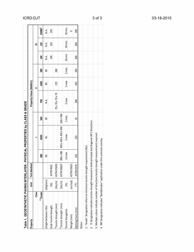
The minimum average roll values (MARV) for the physical requirements of each type of Geosynthetic Paving Interlayer are specified in Table 1. Geosynthetic Paving Interlayer - Physical Properties by Class & Grade (below). The Grade of each Geosynthetic Paving Interlayer material within each Class is designated by the tensile strength requirement(s). Furnish tack coat meeting Section 904.03.A requirements for Performance Grade PG 58 -28 asphalt binder or approved equal. c. Acceptance. Geosynthetics will be accepted based upon a Test Data Certification. Provide the manufacturer’s certification and published installation guidelines to the Engineer at least 10 business days prior to installation. Damaged, defective, or deteriorated geosynthetics will be rejected. Tack Coat will be accepted by General Certification. d. Construction. Install geosynthetic paving interlayer in strict accordance with the manufacturer’s published installation guidelines and as described herein. The Engineer will resolve any conflict between this specification and published guidelines.
Place geosynthetic material on prepared surfaces as shown on typical cross sections.
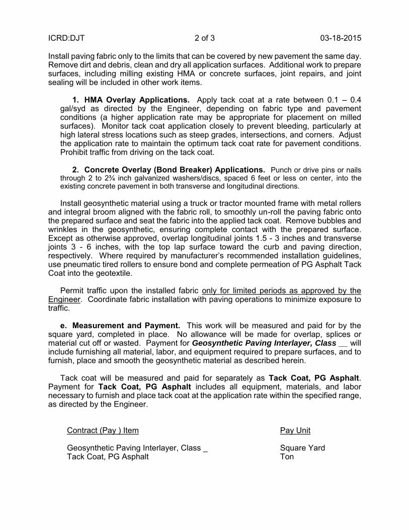
ICRD:DJT 2 of 3 03-18-2015 Install paving fabric only to the limits that can be covered by new pavement the same day. Remove dirt and debris, clean and dry all application surfaces. Additional work to prepare surfaces, including milling existing HMA or concrete surfaces, joint repairs, and joint sealing will be included in other work items.
1. HMA Overlay Applications. Apply tack coat at a rate between 0.1 – 0.4
gal/syd as directed by the Engineer, depending on fabric type and pavement conditions (a higher application rate may be appropriate for placement on milled surfaces). Monitor tack coat application closely to prevent bleeding, particularly at high lateral stress locations such as steep grades, intersections, and corners. Adjust the application rate to maintain the optimum tack coat rate for pavement conditions. Prohibit traffic from driving on the tack coat.
2. Concrete Overlay (Bond Breaker) Applications. Punch or drive pins or nails
through 2 to 2¾ inch galvanized washers/discs, spaced 6 feet or less on center, into the existing concrete pavement in both transverse and longitudinal directions.
Install geosynthetic material using a truck or tractor mounted frame with metal rollers and integral broom aligned with the fabric roll, to smoothly un-roll the paving fabric onto the prepared surface and seat the fabric into the applied tack coat. Remove bubbles and wrinkles in the geosynthetic, ensuring complete contact with the prepared surface. Except as otherwise approved, overlap longitudinal joints 1.5 - 3 inches and transverse joints 3 - 6 inches, with the top lap surface toward the curb and paving direction, respectively. Where required by manufacturer’s recommended installation guidelines, use pneumatic tired rollers to ensure bond and complete permeation of PG Asphalt Tack Coat into the geotextile.
Permit traffic upon the installed fabric only for limited periods as approved by the Engineer. Coordinate fabric installation with paving operations to minimize exposure to traffic. e. Measurement and Payment. This work will be measured and paid for by the square yard, completed in place. No allowance will be made for overlap, splices or material cut off or wasted. Payment for Geosynthetic Paving Interlayer, Class __ will include furnishing all material, labor, and equipment required to prepare surfaces, and to furnish, place and smooth the geosynthetic material as described herein. Tack coat will be measured and paid for separately as Tack Coat, PG Asphalt. Payment for Tack Coat, PG Asphalt includes all equipment, materials, and labor necessary to furnish and place tack coat at the application rate within the specified range, as directed by the Engineer.
Contract (Pay ) Item Pay Unit Geosynthetic Paving Interlayer, Class _ Square Yard Tack Coat, PG Asphalt Ton
ICRD:DJT 3 of 3 03-18-2015
Tabl
e 1.
GEO
SYNT
HETI
C PA
VING
INTE
RLAY
ER -
PHYS
ICAL
PRO
PERT
IES
by C
LASS
& G
RADE
Prop
erty
Uni
tTe
st M
etho
d
Clas
s
1,2 G
rade
280
450X
560
70X
140X
280
100
120
250B
B4
Rein
forc
emen
t Orie
ntat
ion
(Ang
le b
etw
een
ribs)
(deg
rees
)90
4590
N.A.
9090
N.A.
N.A.
N.A.
Grab
Tens
ile St
reng
th(lb
)AS
TM 46
3210
012
025
03 Te
nsile
Stre
ngth
(min
)(lb
s/in
)AS
TM D
5035
70 x
70 x
70 x
7017
028
03 Te
nsile
Stre
ngth
(m
in)
(lbs/
in)
ASTM
D66
3728
0 x 28
045
0 x 45
0 x 45
0 x 45
056
0 x 56
0
Tens
ile El
onga
tion
(%)
12 m
ax5 m
ax5 m
ax5 m
ax5 m
ax5 m
ax50
min
50 m
in50
min
Wei
ght (
min
)(o
z/sy
d)AS
TM D
5621
9
Mel
ting P
oint
(min
)(°F
)AS
TM D
276
325
325
3230
045
045
030
030
030
0
Note
s:
1. "
Grad
e" d
esig
natio
n re
fers
to m
inim
um te
nsile
stre
ngth
requ
irem
ent (
lbs)
.
2. '
X' d
esig
natio
n in
dica
tes t
ensil
e st
reng
th m
easu
red
in b
oth
prin
cipal
and
diag
onal
(45°
) dire
ctio
ns.
3. M
ultip
le va
lues
indi
cate
num
ber o
f dire
ctio
ns te
nsile
stre
ngth
mea
sure
men
t req
uire
d.
4. 'B
B' D
esig
natio
n in
dica
tes "
Bond
brea
ker"
appl
icatio
n un
der t
hin
conc
rete
ove
rlay.
Prop
erty
Val
ue (M
ARV
s)
III
III
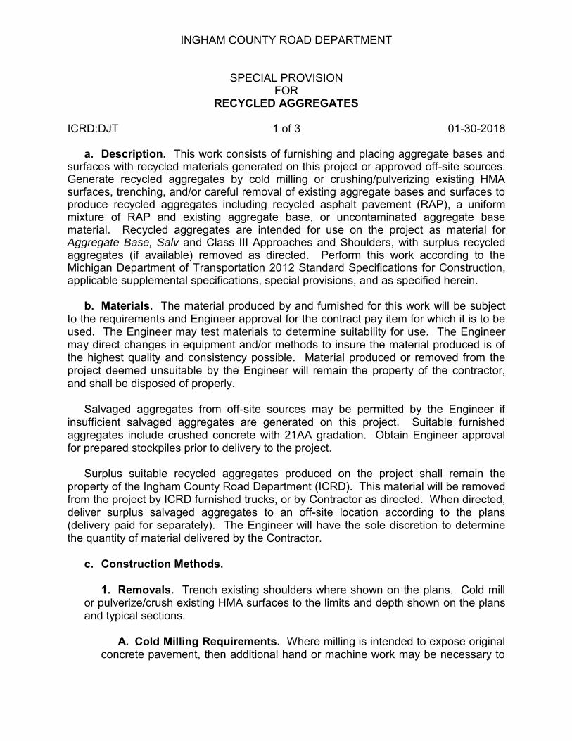
INGHAM COUNTY ROAD DEPARTMENT
SPECIAL PROVISION FOR
RECYCLED AGGREGATES ICRD:DJT 1 of 3 01-30-2018
a. Description. This work consists of furnishing and placing aggregate bases and surfaces with recycled materials generated on this project or approved off-site sources. Generate recycled aggregates by cold milling or crushing/pulverizing existing HMA surfaces, trenching, and/or careful removal of existing aggregate bases and surfaces to produce recycled aggregates including recycled asphalt pavement (RAP), a uniform mixture of RAP and existing aggregate base, or uncontaminated aggregate base material. Recycled aggregates are intended for use on the project as material for Aggregate Base, Salv and Class III Approaches and Shoulders, with surplus recycled aggregates (if available) removed as directed. Perform this work according to the Michigan Department of Transportation 2012 Standard Specifications for Construction, applicable supplemental specifications, special provisions, and as specified herein.
b. Materials. The material produced by and furnished for this work will be subject
to the requirements and Engineer approval for the contract pay item for which it is to be used. The Engineer may test materials to determine suitability for use. The Engineer may direct changes in equipment and/or methods to insure the material produced is of the highest quality and consistency possible. Material produced or removed from the project deemed unsuitable by the Engineer will remain the property of the contractor, and shall be disposed of properly.
Salvaged aggregates from off-site sources may be permitted by the Engineer if
insufficient salvaged aggregates are generated on this project. Suitable furnished aggregates include crushed concrete with 21AA gradation. Obtain Engineer approval for prepared stockpiles prior to delivery to the project.
Surplus suitable recycled aggregates produced on the project shall remain the
property of the Ingham County Road Department (ICRD). This material will be removed from the project by ICRD furnished trucks, or by Contractor as directed. When directed, deliver surplus salvaged aggregates to an off-site location according to the plans (delivery paid for separately). The Engineer will have the sole discretion to determine the quantity of material delivered by the Contractor.
c. Construction Methods.
1. Removals. Trench existing shoulders where shown on the plans. Cold mill or pulverize/crush existing HMA surfaces to the limits and depth shown on the plans and typical sections.
A. Cold Milling Requirements. Where milling is intended to expose original
concrete pavement, then additional hand or machine work may be necessary to

ICRD:DJT 2 of 3 01-30-2018
remove any remaining veneer of HMA pavement left in place behind the milling machine.
Additional milled surface texture (smoothness) requirements will apply when
paving fabric is to be placed directly on the milled surface. Limit operation speed (fpm) to drum (rpm) ratio to obtain the desired surface texture described herein, not to exceed 0.5 at startup. Greater speeds will be permitted provided consistent satisfactory surface texture is attained. Desired surface texture requirements include:
i. Transverse Striations; 18 per ft minimum average ii. Longitudinal Striations; 3 per ft minimum average iii. Striation Length, 1.5 – 2 inches iv. Flat, coplanar surfaces between striations in both directions v. Other striation pattern as approved
B. HMA Surface, Rem, Special. Remove existing HMA surface by cold
milling or crushing/pulverizing the existing HMA to produce suitable recycled aggregate material. Saw cut or cold mill existing pavement for butt joints at intersections and work
limits shown on the plans or as otherwise directed. Remove and/or trim, shape, and compact recycled aggregate materials in place
per typical sections to the lines and grades shown on the plans. Where existing HMA surfaces and/or underlying base materials are removed completely or in part, trim, shape, and compact remaining surfaces within the proposed roadway and approach footprint per typical cross sections according to section 205.
2. Disposal. Temporarily stockpile removed recycled aggregates as necessary
to be used for other contract pay items. Load surplus material onto ICRD or Contractor trucks as directed for delivery to the location(s) shown on the plans. Furnish load tickets for each load removed from the project site by Contractor truck(s). Dispose of unsuitable materials as determined by the Engineer.
3. Aggregate Bases. Place and compact approved recycled aggregate
material used for aggregate base(s) according to section 302. 4. Approaches and Shoulders. Place, grade, and compact approved recycled
aggregate material for shoulder and approaches according to section 307. Where existing shoulders are to be salvaged or conditioned, first remove and dispose of organic material by grading or trimming. Unless otherwise approved or directed, do not plow or grade shoulder material downslope. Condition shoulders by grading, shaping, and compacting surplus crushed, trenched, and/or in-situ materials to finished grades.

ICRD:DJT 3 of 3 01-30-2018
d. Measurement and Payment.
Pay Item Pay Unit
Aggregate Base, Salv, __ inch Square Yard Aggregate Base, Salv Ton Cold Milling HMA Surface, Modified Square Yard HMA Surface, Rem, Special Square Yard Surplus Material Delivery, (Location) Cubic Yard
Aggregate Base, Salv, __ inch will be paid for by the square yard, measured in place. Aggregate Base, Salv, will be paid for by the Ton. Payment for these items includes grading, shaping, and compacting salvaged aggregates according to the plans and standard specifications, including the addition of water to achieve the optimum moisture as necessary to meet the specified density requirements. Where applicable, payment for these items also includes any extra work associated with removal of salvaged aggregate materials from the grade, temporary stockpiling, hauling and placing salvaged material on prepared grades, where shown on the plans. No extra compensation will be made for delivery of salvaged aggregate material from off-site source(s).
The work for Cold Milling HMA Surface, Modified as described herein will be
measured and paid for by the square yard, according to Section 502.04.C, except the work for hauling and disposal will not be included, but will be paid for separately. Extra work required to meet surface and texture requirements specified herein are included with payment for this item, and will not be paid for separately.
Where existing recycled aggregates are removed in part or entirely after crushing or
milling, the items HMA Surface, Rem, Special and Cold Milling HMA Surface, Modified include trimming, shaping, and compacting the residual grade and disposal of unsuitable material. Payment for these items also includes temporary stockpiling recycled aggregates and the loading surplus aggregates on trucks, regardless of whether the Contractor or ICRD hauls the materials.
Where specified, delivery of surplus aggregate materials by the Contractor to the off-
site location(s) specified on the plans will be measured and paid for separately by the cubic yard (LM) as Surplus Material Delivery (Location). The pay quantity for Surplus Material Delivery will be calculated based upon load count (tickets required) at 16.5 CYD per unit or 33 CYD for dual unit, or by measured stockpile dimensions at the point of delivery, as determined by the Engineer. The Engineer will have sole discretion whether to remove some, all, or none of the surplus aggregate(s) paid for by this contract item, or otherwise using ICRD trucks. The Contract quantity will be adjusted accordingly. If all surplus material delivery is made by ICRD trucks, no compensation for this contract item will be made. Extreme adjustments in the quantity of this item will not be grounds for extra compensation or extension of time.

12SP-501E-04
MICHIGAN DEPARTMENT OF TRANSPORTATION
SPECIAL PROVISION
FOR RECYCLED HOT MIX ASPHALT MIXTURE ON LOCAL AGENCY PROJECTS
CFS:KPK 1 of 2 APPR:JWB:CJB:03-13-14
FHWA:APPR:03-13-14 Add the following subsection to subsection 501.02.A.2, on page 234 of the Standard Specifications for Construction.
c. Reclaimed Asphalt Pavement (RAP) and Binder Grade Selection. The method for determining the binder grade in HMA mixtures incorporating RAP is divided into three categories designated Tier 1, Tier 2 and Tier 3. Each tier has a range of percentages that represent the contribution of the RAP binder toward the total binder, by weight. The tiers identified below apply to HMA mixtures with the following exception: Superpave mixture types E3, E3 High Stress, E10, E10 High Stress, E30, E30 High Stress, E50, and E50 High Stress used as leveling or top course must be limited to a maximum of 27 percent RAP binder by weight of the total binder in the mixture.
Recycled materials may be used as a substitute for a portion of the new materials required to produce HMA mixtures in accordance with contract.
● Tier 1 (0% to 17% RAP binder by weight of the total binder in the mixture). No
binder grade adjustment is made to compensate for the stiffness of the asphalt binder in RAP.
● Tier 2 (18% to 27% RAP binder by weight of the total binder in the mixture). For
all mixtures no binder grade change will occur in Tier 2 for all shoulder and temporary road mixtures.
The required asphalt binder grade must be at least one grade lower for the low temperature than the design binder grade required for the specified project mixture type. Lowering the high temperature of the binder one grade is optional. For example, if the design binder grade for the mixture type is PG 58-22, the required grade for the binder in the HMA mixture containing RAP would be a PG 52-28 or a PG 58-28.
For Marshall Mixes, no binder grade change will be required when Average Daily Traffic (ADT) is above 7000 or Commercial Average Daily Traffic (CADT) is above 700. No binder grade change will occur for LVSP, E03 and E1 mixtures used as leveling or top course.
The asphalt binder grade can also be selected using a blending chart for high and low temperatures. Supply the blending chart and the RAP test data used in determining the binder selection according to AASHTO M 323.
● Tier 3 (≥ 28% RAP binder by weight of the total binder in the mixture). The binder

12SP-501E-04 CFS:KPK 2 of 2 03-13-14
grade for the asphalt binder is selected using a blending chart for high and low temperatures per AASHTO M 323. Supply the blending chart and the RAP test data used in determining the binder selection.

KEY
SH
OU
LD
ER
SH
OU
LD
ER
LD
1/2
L
1/2 L
1/2 L
D
A MATCH A
2D
DD
D
W20-1
ROAD
WORK
AHEAD
W20-5
AHEAD
CLOSED
LEFT LANE
W1-6
1/2 L
W1-6
D
2L
BEGINS
ZONE
WORK
R5-18cD
ROAD WORK
END
SPEED
LIMIT
R2-1
X X
SPEED
LIMIT
R2-1
X X
W1-4
W1-4
CON:AE:djf
W4-2
TRAFFIC FLOW
CHANNELIZING DEVICES
LIGHTED ARROW PANEL
TYPE A WARNING FLASHER
1 3 BMM:CRB
K:-DGN-TSR-STDS-ENGLISH-MNTTRF-M0320a.dgn
(REQUIRED)
OCTOBER 2011
IN ONE DIRECTION ONLY
SPEED LIMIT WHERE WORKERS PRESENT
UNDIVIDED ROADWAY USING A REDUCED
FOR CLOSING ONE-HALF OF A FOUR-LANE
TYPICAL TEMPORARY TRAFFIC CONTROL
TYPICAL M0030a-M0080a.
DEPICTED ON THE APPROPRIATE
ADVANCE WORK ZONE SIGNING AS
PLACE THIS SIGN ALONG WITH THE
SEE SHEET 3 OF 3
REFLECTS EXISTING SPEED LIMIT
SIGNING THROUGHOUT WORK AREA
PLUS ADDITIONAL SPEED LIMIT
SIGN = 280 ft2 - TYPE B
ARE NOT IN PLACE.
CROSSROADS IF PERMANENT SIGNS
INDICATED AND AFTER ALL MAJOR
PLACE THROUGHOUT WORK AREA AS
THIS DIRECTION
NO SPEED REDUCTION
PRESENT
WORKERS
WHERE
4 5
R2-1a
BU
FF
ER
D
BU
FF
ER
D
VA
RIE
S
WO
RK
AR
EAD
REDUCTION THIS DIRECTION.
MAXIMUM 10 MPH SPEED
M0320a
10/18/2011
DEPICTED ON TYPICAL M0090a.
THROUGHOUT THE WORK AREA AS
SETS OF SPEED LIMIT SIGNS
PLACE ADDITIONAL SUPPLEMENTAL
SPEED
LIMIT
R2-1
X X
PRESENT
WORKERS
WHERE
4 5
R2-1a
MAINTAINING TRAFFIC
TYPICAL
SHEET
Michigan Department of Transportation
FILE:
OF
TRAFFIC AND SAFETY
PLAN DATE:
DRAWN BY:
CHECKED BY:
REV. NOT TO SCALE

DD
DD
W20-1
ROAD
WORK
AHEAD
SPEED
LIMIT
R2-1
A MATCH A
SH
OU
LD
ER
SH
OU
LD
ER
W20-5
AHEAD
CLOSED
RIGHT LANE
ROAD WORK
END BEGINS
ZONE
WORK
R5-18c
D
SPEED
LIMIT
R2-1
X X
REDUCED
AHEAD
W3-5b
SPEED ZONE
CON:AE:djf
W4-2
2 3 BMM:CRB
OCTOBER 2011
IN ONE DIRECTION ONLY
SPEED LIMIT WHERE WORKERS PRESENT
UNDIVIDED ROADWAY USING A REDUCED
FOR CLOSING ONE-HALF OF A FOUR-LANE
TYPICAL TEMPORARY TRAFFIC CONTROL
M0320a
K:-DGN-TSR-STDS-ENGLISH-MNTTRF-M0320a.dgn
TYPICAL M0030a-M0080a.
DEPICTED ON THE APPROPRIATE
ADVANCE WORK ZONE SIGNING AS
PLACE THIS SIGN ALONG WITH THE
PRESENT
WORKERS
WHERE
10/18/2011
MAINTAINING TRAFFIC
TYPICAL
SHEET
Michigan Department of Transportation
FILE:
OF
TRAFFIC AND SAFETY
PLAN DATE:
DRAWN BY:
CHECKED BY:
REV. NOT TO SCALE
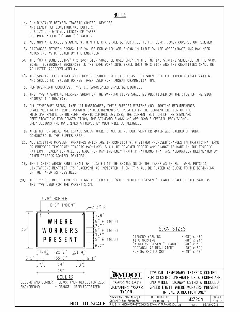
NOTES
2. ALL NON-APPLICABLE SIGNING WITHIN THE CIA SHALL BE MODIFIED TO FIT CONDITIONS, COVERED OR REMOVED.
DISTANCES BETWEEN SIGNS, THE VALUES FOR WHICH ARE SHOWN IN TABLE D, ARE APPROXIMATE AND MAY NEED
ADJUSTING AS DIRECTED BY THE ENGINEER.
3.
6.
NEAREST THE ROADWAY.
THE TYPE A WARNING FLASHER SHOWN ON THE WARNING SIGNS SHALL BE POSITIONED ON THE SIDE OF THE SIGN
8.
CONDUCTED IN THE BUFFER AREA.
WHEN BUFFER AREAS ARE ESTABLISHED, THERE SHALL BE NO EQUIPMENT OR MATERIALS STORED OR WORK
26.
OF THE TAPER AS POSSIBLE.
LIMITATIONS RESTRICT ITS PLACEMENT AS INDICATED, THEN IT SHALL BE PLACED AS CLOSE TO THE BEGINNING
THE LIGHTED ARROW PANEL SHALL BE LOCATED AT THE BEGINNING OF THE TAPER AS SHOWN. WHEN PHYSICAL
21. ALL EXISTING PAVEMENT MARKINGS WHICH ARE IN CONFLICT WITH EITHER PROPOSED CHANGES IN TRAFFIC PATTERNS
OR PROPOSED TEMPORARY TRAFFIC MARKINGS, SHALL BE REMOVED BEFORE ANY CHANGE IS MADE IN THE TRAFFIC
PATTERN. EXCEPTION WILL BE MADE FOR DAYTIME-ONLY TRAFFIC PATTERNS THAT ARE ADEQUATELY DELINEATED BY
OTHER TRAFFIC CONTROL DEVICES.
SIGN SIZES
3A. THE "WORK ZONE BEGINS" (R5-18c) SIGN SHALL BE USED ONLY IN THE INITIAL SIGNING SEQUENCE IN THE WORK
ZONE. SUBSEQUENT SEQUENCES IN THE SAME WORK ZONE SHALL OMIT THIS SIGN AND THE QUANTITIES SHALL BE
ADJUSTED APPROPRIATELY.
CON:AE:djf
3 3 BMM:CRB
OCTOBER 2011
IN ONE DIRECTION ONLY
SPEED LIMIT WHERE WORKERS PRESENT
UNDIVIDED ROADWAY USING A REDUCED
FOR CLOSING ONE-HALF OF A FOUR-LANE
TYPICAL TEMPORARY TRAFFIC CONTROL
M0320a
K:-DGN-TSR-STDS-ENGLISH-MNTTRF-M0320a.dgn
1K. D = DISTANCE BETWEEN TRAFFIC CONTROL DEVICES
L & 1/2 L = MINIMUM LENGTH OF TAPER
M0020a
AND LENGTH OF LONGITUDINAL BUFFERS
SEE FOR "D" AND "L" VALUES
4D. THE SPACING OF CHANNELIZING DEVICES SHOULD NOT EXCEED 45 FEET WHEN USED FOR TAPER CHANNELIZATION,
AND SHOULD NOT EXCEED 90 FEET WHEN USED FOR TANGENT CHANNELIZATION.
THE TYPE OF REFLECTIVE SHEETING USED FOR THE "WHERE WORKERS PRESENT" PLAQUE SHALL BE THE SAME AS
THE TYPE USED FOR THE PARENT SIGN.
29D.
6.8"
3.7"
3.8"
6.1"
6.7"
W HERE
PRESENT
W ORKERS
7" 7"
5" E (MOD)
36" 5" E (MOD)
5" E (MOD)
11.4" 25.2" 11.4"
35.8"6.1"
34"
48"
COLORS
2.3" R
0.9" BORDER
0.6" INDENT
BACKGROUND - ORANGE (REFLECTORIZED)
LEGEND AND BORDER - BLACK (NON-REFLECTORIZED)
"WORKERS PRESENT" PLAQUE - 48" x 36"
W1-6 WARNING - 48" x 24"
DIAMOND WARNING - 48" x 48"
RECTANGULAR REGULATORY - 48" x 60"
R5-18c REGULATORY - 48" x 48"
10/18/2011
7.
ONLY DESIGNS AND MATERIALS APPROVED BY MDOT WILL BE ALLOWED.
SPECIFICATIONS FOR CONSTRUCTION, THE STANDARD PLANS AND APPLICABLE SPECIAL PROVISIONS.
MICHIGAN MANUAL ON UNIFORM TRAFFIC CONTROL DEVICES, THE CURRENT EDITION OF THE STANDARD
SHALL MEET NCHRP 350 CRASHWORTHLY REQUIREMENTS STIPULATED IN THE CURRENT EDITION OF THE
ALL TEMPORARY SIGNS, TYPE III BARRICADES, THEIR SUPPORT SYSTEMS AND LIGHTING REQUIREMENTS
FOR OVERNIGHT CLOSURES, TYPE III BARRICADES SHALL BE LIGHTED.5.
MAINTAINING TRAFFIC
TYPICAL
SHEET
Michigan Department of Transportation
FILE:
OF
TRAFFIC AND SAFETY
PLAN DATE:
DRAWN BY:
CHECKED BY:
REV. NOT TO SCALE

BW
OR
K A
RE
A V
AR
IE
S
SH
OU
LD
ER
SH
OU
LD
ER
KEY
B
L
1/3 L
1/3 L
W20-1
ROAD
WORK
AHEAD
DD
DD
AHEAD
CLOSED
& LEFT LANE
CENTER
D
DD D
W20-1
ROAD
WORK
AHEAD
AHEAD
CLOSED
LANE
CENTER
(MODIFIED)
W20-5a
REDUCTION THIS DIRECTION
MAXIMUM 10MPH SPEED
THIS DIRECTION
NO SPEED REDUCTION
DD
BEGINS
ZONE
WORK
R5-18c
ARE NOT IN PLACE.
CROSSROADS IF PERMANENT SIGNS
INDICATED AND AFTER ALL MAJOR
PLACE THROUGHOUT WORK AREA AS
ROAD WORK
END
ROAD WORK
END
DD
BEGINS
ZONE
WORK
R5-18cSPEED
LIMIT
R2-1
X X
SPEED
LIMIT
R2-1
X X
SPEED
LIMIT
R2-1
X X
SPEED
LIMIT
R2-1
X X
SPEED
LIMIT
R2-1
X X
REDUCED
AHEAD
W3-5b
SPEED ZONE
THROUGHOUT WORK AREA
PLUS ADDITIONAL R2-1’s
SIGN = 188 ft2 - TYPE B
CON:AE:djf
W4-2
IN ONE DIRECTION ONLY
A SINGLE STEP DOWN IN SPEED LIMIT
A MULTI-LANE UNDIVIDED ROADWAY USING
ONLY AND AN ADJACENT THROUGH LANE ON
CLOSING A CENTER-LANE FOR LEFT TURN
TYPICAL TEMPORARY TRAFFIC CONTROL FOR
CHANNELIZING DEVICES
TRAFFIC FLOW
LIGHTED ARROW PANEL
1 2 BMM:CRB M0350a OCTOBER 2011
PW RD/TS/Typicals/Signs/MT NON HWY/M0350a.dgn
LIMIT BEYOND WORK AREA
LEGEND REFLECTS SPEED
TYPICAL M0030a-M0080a.
DEPICTED ON THE APPROPRIATE
ADVANCE WORK ZONE SIGNING AS
PLACE THIS SIGN ALONG WITH THE
AS INDICATED IN THE NOTES.
PLACE THROUGHOUT W ORK AREA
TYPICAL M0030a-M0080a.
DEPICTED ON THE APPROPRIATE
ADVANCE WORK ZONE SIGNING AS
PLACE THIS SIGN ALONG WITH THE
(MODIFIED)
W20-5a
REFLECTS EXISTING SPEED LIMIT
10/18/2011
MAINTAINING TRAFFIC
TYPICAL
SHEET
Michigan Department of Transportation
FILE:
OF
TRAFFIC AND SAFETY
PLAN DATE:
DRAWN BY:
CHECKED BY:
REV. NOT TO SCALE

NOTES
DISTANCES BETWEEN SIGNS, THE VALUES FOR WHICH ARE SHOWN IN TABLE D, ARE APPROXIMATE AND MAY NEED
ADJUSTING AS DIRECTED BY THE ENGINEER.
3.
8.
CONDUCTED IN THE BUFFER AREA.
WHEN BUFFER AREAS ARE ESTABLISHED, THERE SHALL BE NO EQUIPMENT OR MATERIALS STORED OR WORK
2. ALL NON-APPLICABLE SIGNING WITHIN THE CIA SHALL BE MODIFIED TO FIT CONDITIONS, COVERED OR REMOVED.
16B. WHEN REDUCED SPEED LIMITS ARE UTILIZED IN THE WORK AREA, ADDITIONAL SPEED LIMIT SIGNS RETURNING
TRAFFIC TO ITS NORMAL SPEED SHALL BE PLACED BEYOND THE LIMITS OF THE REDUCED SPEED AS INDICATED.
BEGINNING OF THE MERGING TAPER AS POSSIBLE.
PHYSICAL LIMITATIONS RESTRICT ITS PLACEMENT AS INDICATED, THEN IT SHALL BE PLACED AS CLOSE TO THE
THE LIGHTED ARROW PANEL SHALL BE LOCATED AT THE BEGINNING OF THE MERGING TAPER AS SHOWN. WHEN26C.
21. ALL EXISTING PAVEMENT MARKINGS WHICH ARE IN CONFLICT WITH EITHER PROPOSED CHANGES IN TRAFFIC PATTERNS
OR PROPOSED TEMPORARY TRAFFIC MARKINGS, SHALL BE REMOVED BEFORE ANY CHANGE IS MADE IN THE TRAFFIC
PATTERN. EXCEPTION WILL BE MADE FOR DAYTIME-ONLY TRAFFIC PATTERNS THAT ARE ADEQUATELY DELINEATED BY
OTHER TRAFFIC CONTROL DEVICES.
SIGN SIZES
4E. THE MAXIMUM RECOMMENDED DISTANCE(S) BETWEEN CHANNELIZING DEVICES SHOULD BE EQUAL IN FEET TO THE
POSTED SPEED IN MILES PER HOUR ON TAPER(S) AND TWICE THE POSTED SPEED IN THE PARALLEL AREA(S).
3A. THE "WORK ZONE BEGINS" (R5-18c) SIGN SHALL BE USED ONLY IN THE INITIAL SIGNING SEQUENCE IN THE WORK
ZONE. SUBSEQUENT SEQUENCES IN THE SAME WORK ZONE SHALL OMIT THIS SIGN AND THE QUANTITIES SHALL BE
ADJUSTED APPROPRIATELY.
CON:AE:djf
16E. WHEN EXISTING SPEED LIMITS ARE REDUCED MORE THAN 10 MPH, THE SPEED LIMIT SHALL BE STEPPED DOWN IN NO
MORE THAN 10 MPH INCREMENTS.
IN ONE DIRECTION ONLY
A SINGLE STEP DOWN IN SPEED LIMIT
A MULTI-LANE UNDIVIDED ROADWAY USING
ONLY AND AN ADJACENT THROUGH LANE ON
CLOSING A CENTER-LANE FOR LEFT TURN
TYPICAL TEMPORARY TRAFFIC CONTROL FOR
2 2 BMM:CRB
DIAMOND WARNING - 48" x 48"
RECTANGULAR REGULATORY - 48" x 60"
R5-18c REGULATORY - 48" x 48"
OCTOBER 2011
PW RD/TS/Typicals/Signs/MT NON HWY/M0350a.dgn
M0350a
1D. D = DISTANCE BETWEEN TRAFFIC CONTROL DEVICES
L & 1/3 L = MINIMUM LENGTH OF TAPER
B = LENGTH OF LONGITUDINAL BUFFER
M0020aSEE FOR "D," "L," AND "B" VALUES
16A. ADDITIONAL SPEED LIMIT SIGNS REFLECTING THE REDUCED SPEED SHALL BE PLACED AFTER EACH MAJOR
CROSSROAD THAT INTERSECTS THE WORK AREA WHERE THE REDUCED SPEED IS IN EFFECT, AND AT INTERVALS
ALONG THE ROADWAY SUCH THAT NO SPEED LIMIT SIGNS REFLECTING THE REDUCED SPEED ARE MORE THAN
TWO MILES APART.
10/18/2011
6.
FLASHER, SHOWN ON THE WARNING SIGNS, SHALL BE POSITIONED ON THE SIDE OF THE SIGN NEAREST THE ROADWAY.
WHEN CALLED FOR IN THE FHWA ACCEPTANCE LETTER FOR THE SIGN SYSTEM SELECTED, THE TYPE A WARNING
7.
ONLY DESIGNS AND MATERIALS APPROVED BY MDOT WILL BE ALLOWED.
SPECIFICATIONS FOR CONSTRUCTION, THE STANDARD PLANS AND APPLICABLE SPECIAL PROVISIONS.
MICHIGAN MANUAL ON UNIFORM TRAFFIC CONTROL DEVICES, THE CURRENT EDITION OF THE STANDARD
SHALL MEET NCHRP 350 CRASHWORTHLY REQUIREMENTS STIPULATED IN THE CURRENT EDITION OF THE
ALL TEMPORARY SIGNS, TYPE III BARRICADES, THEIR SUPPORT SYSTEMS AND LIGHTING REQUIREMENTS
FOR OVERNIGHT CLOSURES, TYPE III BARRICADES SHALL BE LIGHTED.5.
MAINTAINING TRAFFIC
TYPICAL
SHEET
Michigan Department of Transportation
FILE:
OF
TRAFFIC AND SAFETY
PLAN DATE:
DRAWN BY:
CHECKED BY:
REV. NOT TO SCALE

BW
OR
K A
RE
A V
AR
IE
S
SH
OU
LD
ER
SH
OU
LD
ER
KEY
L
1/3 L
W20-1
ROAD
WORK
AHEAD
DD
DD
AHEAD
CLOSED
& LEFT LANE
CENTER
D
D
DD
D
B
1/3 L
LD
(MODIFIED)
W20-5aAHEAD
CLOSED
& LEFT LANE
CENTER
D
W20-1
ROAD
WORK
AHEAD
WO
RK
AR
EA
VA
RIE
S
LIMIT BEYOND WORK AREA
LEGEND REFLECTS SPEED
BEGINS
ZONE
WORK
R5-18cD
D
BEGINS
ZONE
WORK
R5-18c
ROAD WORK
END
ROAD WORK
END
D
W4-2
SPEED
LIMIT
R2-1
X X
SPEED
LIMIT
R2-1
X X
SPEED
LIMIT
R2-1
X X
REDUCED
AHEAD
W3-5b
SPEED ZONE
SPEED
LIMIT
R2-1
X X
SPEED
LIMIT
R2-1
X X
SPEED
LIMIT
R2-1
X X
W4-2REDUCED
AHEAD
W3-5b
SPEED ZONE
THROUGHOUT WORK AREA
PLUS ADDITIONAL R2-1’s
SIGN = 240 ft2 - TYPE B
CON:AE:djf
STEP DOWN IN SPEED LIMIT
UNDIVIDED ROADWAY USING A SINGLE
EACH DIRECTION ON A MULTI-LANE
ONLY AND AN ADJACENT THROUGH LANE IN
CLOSING A CENTER-LANE FOR LEFT TURN
TYPICAL TEMPORARY TRAFFIC CONTROL FOR
CHANNELIZING DEVICES
TRAFFIC FLOW
LIGHTED ARROW PANEL
1 2 BMM:CRB M0380a
PW RD/TS/Typicals/Signs/MT NON FWY/M0380a.dgn
OCTOBER 2011
TYPICAL M0030a-M0080a.
DEPICTED ON THE APPROPRIATE
ADVANCE WORK ZONE SIGNING AS
PLACE THIS SIGN ALONG WITH THE
AS INDICATED IN THE NOTES.
PLACE THROUGHOUT W ORK AREA
TYPICAL M0030a-M0080a.
DEPICTED ON THE APPROPRIATE
ADVANCE WORK ZONE SIGNING AS
PLACE THIS SIGN ALONG WITH THE
(MODIFIED)
W20-5a
AS INDICATED IN THE NOTES.
PLACE THROUGHOUT W ORK AREA
BEYOND W ORK AREA.
LEGEND REFLECTS SPEED LIMIT
10/18/2011
MAINTAINING TRAFFIC
TYPICAL
SHEET
Michigan Department of Transportation
FILE:
OF
TRAFFIC AND SAFETY
PLAN DATE:
DRAWN BY:
CHECKED BY:
REV. NOT TO SCALE
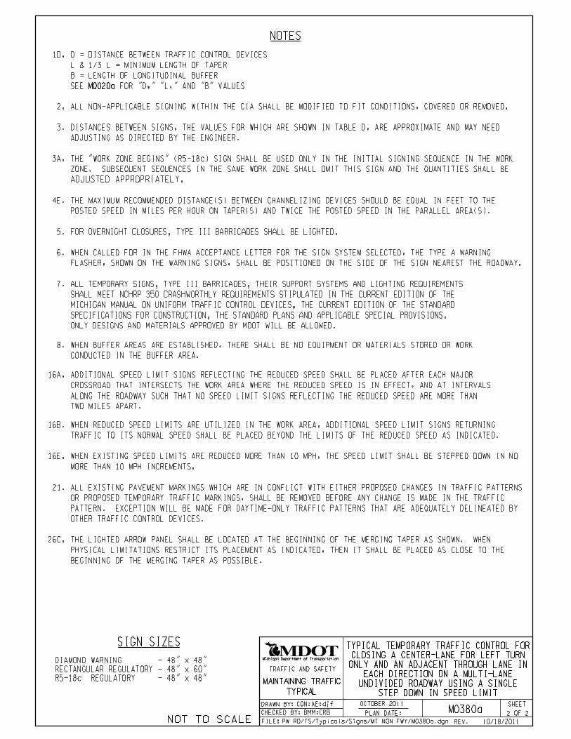
NOTES
DISTANCES BETWEEN SIGNS, THE VALUES FOR WHICH ARE SHOWN IN TABLE D, ARE APPROXIMATE AND MAY NEED
ADJUSTING AS DIRECTED BY THE ENGINEER.
3.
8.
CONDUCTED IN THE BUFFER AREA.
WHEN BUFFER AREAS ARE ESTABLISHED, THERE SHALL BE NO EQUIPMENT OR MATERIALS STORED OR WORK
2. ALL NON-APPLICABLE SIGNING WITHIN THE CIA SHALL BE MODIFIED TO FIT CONDITIONS, COVERED OR REMOVED.
16B. WHEN REDUCED SPEED LIMITS ARE UTILIZED IN THE WORK AREA, ADDITIONAL SPEED LIMIT SIGNS RETURNING
TRAFFIC TO ITS NORMAL SPEED SHALL BE PLACED BEYOND THE LIMITS OF THE REDUCED SPEED AS INDICATED.
BEGINNING OF THE MERGING TAPER AS POSSIBLE.
PHYSICAL LIMITATIONS RESTRICT ITS PLACEMENT AS INDICATED, THEN IT SHALL BE PLACED AS CLOSE TO THE
THE LIGHTED ARROW PANEL SHALL BE LOCATED AT THE BEGINNING OF THE MERGING TAPER AS SHOWN. WHEN26C.
21. ALL EXISTING PAVEMENT MARKINGS WHICH ARE IN CONFLICT WITH EITHER PROPOSED CHANGES IN TRAFFIC PATTERNS
OR PROPOSED TEMPORARY TRAFFIC MARKINGS, SHALL BE REMOVED BEFORE ANY CHANGE IS MADE IN THE TRAFFIC
PATTERN. EXCEPTION WILL BE MADE FOR DAYTIME-ONLY TRAFFIC PATTERNS THAT ARE ADEQUATELY DELINEATED BY
OTHER TRAFFIC CONTROL DEVICES.
SIGN SIZES
4E. THE MAXIMUM RECOMMENDED DISTANCE(S) BETWEEN CHANNELIZING DEVICES SHOULD BE EQUAL IN FEET TO THE
POSTED SPEED IN MILES PER HOUR ON TAPER(S) AND TWICE THE POSTED SPEED IN THE PARALLEL AREA(S).
3A. THE "WORK ZONE BEGINS" (R5-18c) SIGN SHALL BE USED ONLY IN THE INITIAL SIGNING SEQUENCE IN THE WORK
ZONE. SUBSEQUENT SEQUENCES IN THE SAME WORK ZONE SHALL OMIT THIS SIGN AND THE QUANTITIES SHALL BE
ADJUSTED APPROPRIATELY.
STEP DOWN IN SPEED LIMIT
UNDIVIDED ROADWAY USING A SINGLE
EACH DIRECTION ON A MULTI-LANE
ONLY AND AN ADJACENT THROUGH LANE IN
CLOSING A CENTER-LANE FOR LEFT TURN
TYPICAL TEMPORARY TRAFFIC CONTROL FOR
CON:AE:djf
16E. WHEN EXISTING SPEED LIMITS ARE REDUCED MORE THAN 10 MPH, THE SPEED LIMIT SHALL BE STEPPED DOWN IN NO
MORE THAN 10 MPH INCREMENTS.
2 2 BMM:CRB
R5-18c REGULATORY - 48" x 48"
DIAMOND WARNING - 48" x 48"
RECTANGULAR REGULATORY - 48" x 60"
PW RD/TS/Typicals/Signs/MT NON FWY/M0380a.dgn
OCTOBER 2011
M0380a
16A. ADDITIONAL SPEED LIMIT SIGNS REFLECTING THE REDUCED SPEED SHALL BE PLACED AFTER EACH MAJOR
CROSSROAD THAT INTERSECTS THE WORK AREA WHERE THE REDUCED SPEED IS IN EFFECT, AND AT INTERVALS
ALONG THE ROADWAY SUCH THAT NO SPEED LIMIT SIGNS REFLECTING THE REDUCED SPEED ARE MORE THAN
TWO MILES APART.
1D. D = DISTANCE BETWEEN TRAFFIC CONTROL DEVICES
L & 1/3 L = MINIMUM LENGTH OF TAPER
B = LENGTH OF LONGITUDINAL BUFFER
M0020aSEE FOR "D," "L," AND "B" VALUES
10/18/2011
6.
FLASHER, SHOWN ON THE WARNING SIGNS, SHALL BE POSITIONED ON THE SIDE OF THE SIGN NEAREST THE ROADWAY.
WHEN CALLED FOR IN THE FHWA ACCEPTANCE LETTER FOR THE SIGN SYSTEM SELECTED, THE TYPE A WARNING
7.
ONLY DESIGNS AND MATERIALS APPROVED BY MDOT WILL BE ALLOWED.
SPECIFICATIONS FOR CONSTRUCTION, THE STANDARD PLANS AND APPLICABLE SPECIAL PROVISIONS.
MICHIGAN MANUAL ON UNIFORM TRAFFIC CONTROL DEVICES, THE CURRENT EDITION OF THE STANDARD
SHALL MEET NCHRP 350 CRASHWORTHLY REQUIREMENTS STIPULATED IN THE CURRENT EDITION OF THE
ALL TEMPORARY SIGNS, TYPE III BARRICADES, THEIR SUPPORT SYSTEMS AND LIGHTING REQUIREMENTS
FOR OVERNIGHT CLOSURES, TYPE III BARRICADES SHALL BE LIGHTED.5.
MAINTAINING TRAFFIC
TYPICAL
SHEET
Michigan Department of Transportation
FILE:
OF
TRAFFIC AND SAFETY
PLAN DATE:
DRAWN BY:
CHECKED BY:
REV. NOT TO SCALE

KEY
B
VA
RIE
S
WO
RK
AR
EA
1/2 L
D LIMIT BEYOND WORK AREA
LEGEND REFLECTS SPEED
2D
DD
W20-1
ROAD
WORK
AHEAD
SH
OU
LD
ER
SH
OU
LD
ER
D
TEMPORARY PAVEMENT MARKINGS
W20-1
ROAD
WORK
AHEAD DD
1/3 L
D
1/2
AHEAD
CLOSED
LANE
CENTER
(MODIFIED)
W20-5a
1/2 L
W1-6
1/2 L
W1-6
DD
BEGINS
ZONE
WORK
R5-18c
ROAD WORK
END
BEGINS
ZONE
WORK
R5-18c
ARE NOT IN PLACE.
CROSSROADS IF PERMANENT SIGNS
INDICATED AND AFTER ALL MAJOR
PLACE THROUGHOUT WORK AREA AS
ROAD WORK
END
THIS DIRECTION
NO SPEED REDUCTION
REDUCTION THIS DIRECTION
MAXIMUM 10MPH SPEED
DD
SPEED
LIMIT
R2-1
X X
SPEED
LIMIT
R2-1
X X
SPEED
LIMIT
R2-1
X X
SPEED
LIMIT
R2-1
X X
SPEED
LIMIT
R2-1
X X
REDUCED
AHEAD
W3-5b
SPEED ZONE
W1-4b
W1-4b
THROUGHOUT WORK AREA
PLUS ADDITIONAL R2-1’s
SIGN = 220 ft2 - TYPE B
CON:AE:djf
IN ONE DIRECTION ONLY
SINGLE STEP DOWN IN SPEED LIMIT
THROUGH LANES IN EACH DIRECTION USING A
UNDIVIDED ROADWAY AND MAINTAINING TWO
FOR CLOSING ONE LANE OF A FIVE-LANE
TYPICAL TEMPORARY TRAFFIC CONTROL
CHANNELIZING DEVICES
TRAFFIC FLOW
TYPE A WARNING FLASHER
1 2 BMM:CRB M0410a
K:-DGN-TSR-STDS-ENGLISH-MNTTRF-M0410a.dgn
(REQUIRED)
OCTOBER 2011
TYPICAL M0030a-M0080a.
DEPICTED ON THE APPROPRIATE
ADVANCE WORK ZONE SIGNING AS
PLACE THIS SIGN ALONG WITH THE
AS INDICATED IN THE NOTES.
PLACE THROUGHOUT W ORK AREA
TYPICAL M0030a-M0080a.
DEPICTED ON THE APPROPRIATE
ADVANCE WORK ZONE SIGNING AS
PLACE THIS SIGN ALONG WITH THE
REFLECTS EXISTING SPEED LIMIT
10/19/2011
MAINTAINING TRAFFIC
TYPICAL
SHEET
Michigan Department of Transportation
FILE:
OF
TRAFFIC AND SAFETY
PLAN DATE:
DRAWN BY:
CHECKED BY:
REV. NOT TO SCALE

NOTES
DISTANCES BETWEEN SIGNS, THE VALUES FOR WHICH ARE SHOWN IN TABLE D, ARE APPROXIMATE AND MAY NEED
ADJUSTING AS DIRECTED BY THE ENGINEER.
3.
6.
NEAREST THE ROADWAY.
THE TYPE A WARNING FLASHER SHOWN ON THE WARNING SIGNS SHALL BE POSITIONED ON THE SIDE OF THE SIGN
8.
CONDUCTED IN THE BUFFER AREA.
WHEN BUFFER AREAS ARE ESTABLISHED, THERE SHALL BE NO EQUIPMENT OR MATERIALS STORED OR WORK
2. ALL NON-APPLICABLE SIGNING WITHIN THE CIA SHALL BE MODIFIED TO FIT CONDITIONS, COVERED OR REMOVED.
16B. WHEN REDUCED SPEED LIMITS ARE UTILIZED IN THE WORK AREA, ADDITIONAL SPEED LIMIT SIGNS RETURNING
TRAFFIC TO ITS NORMAL SPEED SHALL BE PLACED BEYOND THE LIMITS OF THE REDUCED SPEED AS INDICATED.
21. ALL EXISTING PAVEMENT MARKINGS WHICH ARE IN CONFLICT WITH EITHER PROPOSED CHANGES IN TRAFFIC PATTERNS
OR PROPOSED TEMPORARY TRAFFIC MARKINGS, SHALL BE REMOVED BEFORE ANY CHANGE IS MADE IN THE TRAFFIC
PATTERN. EXCEPTION WILL BE MADE FOR DAYTIME-ONLY TRAFFIC PATTERNS THAT ARE ADEQUATELY DELINEATED BY
OTHER TRAFFIC CONTROL DEVICES.
SIGN SIZES
4E. THE MAXIMUM RECOMMENDED DISTANCE(S) BETWEEN CHANNELIZING DEVICES SHOULD BE EQUAL IN FEET TO THE
POSTED SPEED IN MILES PER HOUR ON TAPER(S) AND TWICE THE POSTED SPEED IN THE PARALLEL AREA(S).
3A. THE "WORK ZONE BEGINS" (R5-18c) SIGN SHALL BE USED ONLY IN THE INITIAL SIGNING SEQUENCE IN THE WORK
ZONE. SUBSEQUENT SEQUENCES IN THE SAME WORK ZONE SHALL OMIT THIS SIGN AND THE QUANTITIES SHALL BE
ADJUSTED APPROPRIATELY.
IN ONE DIRECTION ONLY
SINGLE STEP DOWN IN SPEED LIMIT
THROUGH LANES IN EACH DIRECTION USING A
UNDIVIDED ROADWAY AND MAINTAINING TWO
FOR CLOSING ONE LANE OF A FIVE-LANE
TYPICAL TEMPORARY TRAFFIC CONTROL
CON:AE:djf
16E. WHEN EXISTING SPEED LIMITS ARE REDUCED MORE THAN 10 MPH, THE SPEED LIMIT SHALL BE STEPPED DOWN IN NO
MORE THAN 10 MPH INCREMENTS.
2 2 BMM:CRB
DIAMOND WARNING - 48" x 48"
W1-6 WARNING - 48" x 24"
RECTANGULAR REGULATORY - 48" x 60"
R5-18c REGULATORY - 48" x 48"
K:-DGN-TSR-STDS-ENGLISH-MNTTRF-M0410a.dgn
OCTOBER 2011
M0410a
1F. D = DISTANCE BETWEEN TRAFFIC CONTROL DEVICES
B = LENGTH OF LONGITUDINAL BUFFER
1/2 L, AND 1/3 L = MINIMUM LENGTH OF TAPER
M0020aSEE FOR "D," "L," AND "B" VALUES
16A. ADDITIONAL SPEED LIMIT SIGNS REFLECTING THE REDUCED SPEED SHALL BE PLACED AFTER EACH MAJOR
CROSSROAD THAT INTERSECTS THE WORK AREA WHERE THE REDUCED SPEED IS IN EFFECT, AND AT INTERVALS
ALONG THE ROADWAY SUCH THAT NO SPEED LIMIT SIGNS REFLECTING THE REDUCED SPEED ARE MORE THAN
TWO MILES APART.
10/19/2011
7.
ONLY DESIGNS AND MATERIALS APPROVED BY MDOT WILL BE ALLOWED.
SPECIFICATIONS FOR CONSTRUCTION, THE STANDARD PLANS AND APPLICABLE SPECIAL PROVISIONS.
MICHIGAN MANUAL ON UNIFORM TRAFFIC CONTROL DEVICES, THE CURRENT EDITION OF THE STANDARD
SHALL MEET NCHRP 350 CRASHWORTHLY REQUIREMENTS STIPULATED IN THE CURRENT EDITION OF THE
ALL TEMPORARY SIGNS, TYPE III BARRICADES, THEIR SUPPORT SYSTEMS AND LIGHTING REQUIREMENTS
FOR OVERNIGHT CLOSURES, TYPE III BARRICADES SHALL BE LIGHTED.5.
MAINTAINING TRAFFIC
TYPICAL
SHEET
Michigan Department of Transportation
FILE:
OF
TRAFFIC AND SAFETY
PLAN DATE:
DRAWN BY:
CHECKED BY:
REV. NOT TO SCALE

KEY
W20-1
ROAD
WORK
AHEAD
B
SH
OU
LD
ER
SH
OU
LD
ER
DD
1/3 L
2D
VA
RIE
S
WO
RK
AR
EA
DL
AHEAD
CLOSED
LANE
CENTER
(MODIFIED)
W20-5a
1/2 L
1/2 L
W20-1
ROAD
WORK
AHEAD
DD
DD
W20-5
AHEAD
CLOSED
RIGHT LANE
D
LIMIT BEYOND WORK AREA
LEGEND REFLECTS SPEED
1/2 L
W1-6
W1-6
2L
DD
REDUCTION THIS DIRECTION
MAXIMUM 10MPH SPEED
DD
1/2 D
ROAD WORK
END
BEGINS
ZONE
WORK
R5-18c
ARE NOT IN PLACE.
CROSSROADS IF PERMANENT SIGNS
INDICATED AND AFTER ALL MAJOR
PLACE THROUGHOUT WORK AREA AS
THIS DIRECTION
NO SPEED REDUCTION
ROAD WORK
END BEGINS
ZONE
WORK
R5-18c
SPEED
LIMIT
R2-1
X X
SPEED
LIMIT
R2-1
X X
SPEED
LIMIT
R2-1
X X
SPEED
LIMIT
R2-1
X X
REDUCED
AHEAD
W3-5b
SPEED ZONE
SPEED
LIMIT
R2-1
X X
THROUGHOUT WORK AREA
PLUS ADDITIONAL R2-1’s
SIGN = 252 ft2 - TYPE B
W1-4
W1-4
CON:AE:djf
IN ONE DIRECTION ONLY
A SINGLE STEP DOWN IN SPEED LIMIT
OF A FIVE-LANE UNDIVIDED ROADWAY USING
CLOSING TWO ADJACENT THROUGH LANES
TYPICAL TEMPORARY TRAFFIC CONTROL FOR
W4-2
CHANNELIZING DEVICES
TYPE A WARNING FLASHER
TRAFFIC FLOW
LIGHTED ARROW PANEL
1 2 BMM:CRB M0440a
(REQUIRED)
OCTOBER 2011
K:-DGN-TSR-STDS-ENGLISH-MNTTRF-M0440a.dgn
TYPICAL M0030a-M0080a.
DEPICTED ON THE APPROPRIATE
ADVANCE WORK ZONE SIGNING AS
PLACE THIS SIGN ALONG WITH THE
AS INDICATED IN THE NOTES.
PLACE THROUGHOUT W ORK AREA
TYPICAL M0030a-M0080a.
DEPICTED ON THE APPROPRIATE
ADVANCE WORK ZONE SIGNING AS
PLACE THIS SIGN ALONG WITH THE
REFLECTS EXISTING SPEED LIMIT
10/20/2011
MAINTAINING TRAFFIC
TYPICAL
SHEET
Michigan Department of Transportation
FILE:
OF
TRAFFIC AND SAFETY
PLAN DATE:
DRAWN BY:
CHECKED BY:
REV. NOT TO SCALE

NOTES
DISTANCES BETWEEN SIGNS, THE VALUES FOR WHICH ARE SHOWN IN TABLE D, ARE APPROXIMATE AND MAY NEED
ADJUSTING AS DIRECTED BY THE ENGINEER.
3.
6.
NEAREST THE ROADWAY.
THE TYPE A WARNING FLASHER SHOWN ON THE WARNING SIGNS SHALL BE POSITIONED ON THE SIDE OF THE SIGN
8.
CONDUCTED IN THE BUFFER AREA.
WHEN BUFFER AREAS ARE ESTABLISHED, THERE SHALL BE NO EQUIPMENT OR MATERIALS STORED OR WORK
2. ALL NON-APPLICABLE SIGNING WITHIN THE CIA SHALL BE MODIFIED TO FIT CONDITIONS, COVERED OR REMOVED.
16B. WHEN REDUCED SPEED LIMITS ARE UTILIZED IN THE WORK AREA, ADDITIONAL SPEED LIMIT SIGNS RETURNING
TRAFFIC TO ITS NORMAL SPEED SHALL BE PLACED BEYOND THE LIMITS OF THE REDUCED SPEED AS INDICATED.
SIGN SIZES
21. ALL EXISTING PAVEMENT MARKINGS WHICH ARE IN CONFLICT WITH EITHER PROPOSED CHANGES IN TRAFFIC PATTERNS
OR PROPOSED TEMPORARY TRAFFIC MARKINGS, SHALL BE REMOVED BEFORE ANY CHANGE IS MADE IN THE TRAFFIC
PATTERN. EXCEPTION WILL BE MADE FOR DAYTIME-ONLY TRAFFIC PATTERNS THAT ARE ADEQUATELY DELINEATED BY
OTHER TRAFFIC CONTROL DEVICES.
26.
OF THE TAPER AS POSSIBLE.
LIMITATIONS RESTRICT ITS PLACEMENT AS INDICATED, THEN IT SHALL BE PLACED AS CLOSE TO THE BEGINNING
THE LIGHTED ARROW PANEL SHALL BE LOCATED AT THE BEGINNING OF THE TAPER AS SHOWN. WHEN PHYSICAL
4E. THE MAXIMUM RECOMMENDED DISTANCE(S) BETWEEN CHANNELIZING DEVICES SHOULD BE EQUAL IN FEET TO THE
POSTED SPEED IN MILES PER HOUR ON TAPER(S) AND TWICE THE POSTED SPEED IN THE PARALLEL AREA(S).
3A. THE "WORK ZONE BEGINS" (R5-18c) SIGN SHALL BE USED ONLY IN THE INITIAL SIGNING SEQUENCE IN THE WORK
ZONE. SUBSEQUENT SEQUENCES IN THE SAME WORK ZONE SHALL OMIT THIS SIGN AND THE QUANTITIES SHALL BE
ADJUSTED APPROPRIATELY.
CON:AE:djf
IN ONE DIRECTION ONLY
A SINGLE STEP DOWN IN SPEED LIMIT
OF A FIVE-LANE UNDIVIDED ROADWAY USING
CLOSING TWO ADJACENT THROUGH LANES
TYPICAL TEMPORARY TRAFFIC CONTROL FOR
16E. WHEN EXISTING SPEED LIMITS ARE REDUCED MORE THAN 10 MPH, THE SPEED LIMIT SHALL BE STEPPED DOWN IN NO
MORE THAN 10 MPH INCREMENTS.
2 2 BMM:CRB
DIAMOND WARNING - 48" x 48"
W1-6 WARNING - 48" x 24"
RECTANGULAR REGULATORY - 48" x 60"
R5-18c REGULATORY - 48" x 48"
K:-DGN-TSR-STDS-ENGLISH-MNTTRF-M0440a.dgn
OCTOBER 2011
M0440a
1E. D = DISTANCE BETWEEN TRAFFIC CONTROL DEVICES
B = LENGTH OF LONGITUDINAL BUFFER
L, 1/2 L, AND 1/3 L = MINIMUM LENGTH OF TAPER
M0020aSEE FOR "D," "L," AND "B" VALUES
16A. ADDITIONAL SPEED LIMIT SIGNS REFLECTING THE REDUCED SPEED SHALL BE PLACED AFTER EACH MAJOR
CROSSROAD THAT INTERSECTS THE WORK AREA WHERE THE REDUCED SPEED IS IN EFFECT, AND AT INTERVALS
ALONG THE ROADWAY SUCH THAT NO SPEED LIMIT SIGNS REFLECTING THE REDUCED SPEED ARE MORE THAN
TWO MILES APART.
10/20/2011
7.
ONLY DESIGNS AND MATERIALS APPROVED BY MDOT WILL BE ALLOWED.
SPECIFICATIONS FOR CONSTRUCTION, THE STANDARD PLANS AND APPLICABLE SPECIAL PROVISIONS.
MICHIGAN MANUAL ON UNIFORM TRAFFIC CONTROL DEVICES, THE CURRENT EDITION OF THE STANDARD
SHALL MEET NCHRP 350 CRASHWORTHLY REQUIREMENTS STIPULATED IN THE CURRENT EDITION OF THE
ALL TEMPORARY SIGNS, TYPE III BARRICADES, THEIR SUPPORT SYSTEMS AND LIGHTING REQUIREMENTS
FOR OVERNIGHT CLOSURES, TYPE III BARRICADES SHALL BE LIGHTED.5.
MAINTAINING TRAFFIC
TYPICAL
SHEET
Michigan Department of Transportation
FILE:
OF
TRAFFIC AND SAFETY
PLAN DATE:
DRAWN BY:
CHECKED BY:
REV. NOT TO SCALE

KEY
D
LIMIT BEYOND WORK AREA
LEGEND REFLECTS SPEED
DD
D
(MODIFIED)
W20-5a
AHEAD
CLOSED
& LEFT LANE
CENTER
D
W20-1
ROAD
WORK
AHEAD
D
B
SH
OU
LD
ER
SH
OU
LD
ER
D
1/3 L
L
1/2
L
VA
RIE
S
WO
RK
AR
EA
1/2
L
D
1/2
LIMIT BEYOND WORK AREA
LEGEND REFLECTS SPEED
TEMPORARY PAVEMENT MARKINGS
W1-6
W1-6
1/2
L
2D
DD
D
W20-1
ROAD
WORK
AHEAD
DD
BEGINS
ZONE
WORK
R5-18c
D
BEGINS
ZONE
WORK
R5-18c
ROAD WORK
END
ROAD WORK
END
W4-2
REDUCED
AHEAD
W3-5b
SPEED ZONE
SPEED
LIMIT
R2-1
X XSPEED
LIMIT
R2-1
X X
SPEED
LIMIT
R2-1
X X
SPEED
LIMIT
R2-1
X X
SPEED
LIMIT
R2-1
X XSPEED
LIMIT
R2-1
X X
REDUCED
AHEAD
W3-5b
SPEED ZONE
THROUGHOUT WORK AREA
PLUS ADDITIONAL R2-1’s
SIGN = 288 ft2 - TYPE B
W1-4b
W1-4b
CON:AE:djf
DOWN IN SPEED LIMIT
ROADWAY USING A SINGLE STEP
LANES OF A FIVE-LANE UNDIVIDED
FOR CLOSING TWO ADJACENT THROUGH
TYPICAL TEMPORARY TRAFFIC CONTROL
CHANNELIZING DEVICES
TYPE A WARNING FLASHER
TRAFFIC FLOW
LIGHTED ARROW PANEL
1 2 BMM:CRB M0470a
K:-DGN-TSR-STDS-ENGLISH-MNTTRF-M0470a.dgn
(REQUIRED)
10/20/2011
OCTOBER 2011
TYPICAL M0030a-M0080a.
DEPICTED ON THE APPROPRIATE
ADVANCE WORK ZONE SIGNING AS
PLACE THIS SIGN ALONG WITH THE
AS INDICATED IN THE NOTES.
PLACE THROUGHOUT W ORK AREA
AS INDICATED IN THE NOTES.
PLACE THROUGHOUT W ORK AREA
TYPICAL M0030a-M0080a.
DEPICTED ON THE APPROPRIATE
ADVANCE WORK ZONE SIGNING AS
PLACE THIS SIGN ALONG WITH THE
MAINTAINING TRAFFIC
TYPICAL
SHEET
Michigan Department of Transportation
FILE:
OF
TRAFFIC AND SAFETY
PLAN DATE:
DRAWN BY:
CHECKED BY:
REV. NOT TO SCALE

NOTES
DISTANCES BETWEEN SIGNS, THE VALUES FOR WHICH ARE SHOWN IN TABLE D, ARE APPROXIMATE AND MAY NEED
ADJUSTING AS DIRECTED BY THE ENGINEER.
3.
6.
NEAREST THE ROADWAY.
THE TYPE A WARNING FLASHER SHOWN ON THE WARNING SIGNS SHALL BE POSITIONED ON THE SIDE OF THE SIGN
8.
CONDUCTED IN THE BUFFER AREA.
WHEN BUFFER AREAS ARE ESTABLISHED, THERE SHALL BE NO EQUIPMENT OR MATERIALS STORED OR WORK
2. ALL NON-APPLICABLE SIGNING WITHIN THE CIA SHALL BE MODIFIED TO FIT CONDITIONS, COVERED OR REMOVED.
16B. WHEN REDUCED SPEED LIMITS ARE UTILIZED IN THE WORK AREA, ADDITIONAL SPEED LIMIT SIGNS RETURNING
TRAFFIC TO ITS NORMAL SPEED SHALL BE PLACED BEYOND THE LIMITS OF THE REDUCED SPEED AS INDICATED.
21. ALL EXISTING PAVEMENT MARKINGS WHICH ARE IN CONFLICT WITH EITHER PROPOSED CHANGES IN TRAFFIC PATTERNS
OR PROPOSED TEMPORARY TRAFFIC MARKINGS, SHALL BE REMOVED BEFORE ANY CHANGE IS MADE IN THE TRAFFIC
PATTERN. EXCEPTION WILL BE MADE FOR DAYTIME-ONLY TRAFFIC PATTERNS THAT ARE ADEQUATELY DELINEATED BY
OTHER TRAFFIC CONTROL DEVICES.
BEGINNING OF THE MERGING TAPER AS POSSIBLE.
PHYSICAL LIMITATIONS RESTRICT ITS PLACEMENT AS INDICATED, THEN IT SHALL BE PLACED AS CLOSE TO THE
THE LIGHTED ARROW PANEL SHALL BE LOCATED AT THE BEGINNING OF THE MERGING TAPER AS SHOWN. WHEN26C.
SIGN SIZES
4E. THE MAXIMUM RECOMMENDED DISTANCE(S) BETWEEN CHANNELIZING DEVICES SHOULD BE EQUAL IN FEET TO THE
POSTED SPEED IN MILES PER HOUR ON TAPER(S) AND TWICE THE POSTED SPEED IN THE PARALLEL AREA(S).
3A. THE "WORK ZONE BEGINS" (R5-18c) SIGN SHALL BE USED ONLY IN THE INITIAL SIGNING SEQUENCE IN THE WORK
ZONE. SUBSEQUENT SEQUENCES IN THE SAME WORK ZONE SHALL OMIT THIS SIGN AND THE QUANTITIES SHALL BE
ADJUSTED APPROPRIATELY.
DOWN IN SPEED LIMIT
ROADWAY USING A SINGLE STEP
LANES OF A FIVE-LANE UNDIVIDED
FOR CLOSING TWO ADJACENT THROUGH
TYPICAL TEMPORARY TRAFFIC CONTROL
CON:AE:djf
16E. WHEN EXISTING SPEED LIMITS ARE REDUCED MORE THAN 10 MPH, THE SPEED LIMIT SHALL BE STEPPED DOWN IN NO
MORE THAN 10 MPH INCREMENTS.
2 2 BMM:CRB
DIAMOND WARNING - 48" x 48"
W1-6 WARNING - 48" x 24"
RECTANGULAR REGULATORY - 48" x 60"
R5-18c REGULATORY - 48" x 48"
K:-DGN-TSR-STDS-ENGLISH-MNTTRF-M0470a.dgn
OCTOBER 2011
M0470a
10/20/2011
1E. D = DISTANCE BETWEEN TRAFFIC CONTROL DEVICES
B = LENGTH OF LONGITUDINAL BUFFER
L, 1/2 L, AND 1/3 L = MINIMUM LENGTH OF TAPER
M0020aSEE FOR "D," "L," AND "B" VALUES
16A. ADDITIONAL SPEED LIMIT SIGNS REFLECTING THE REDUCED SPEED SHALL BE PLACED AFTER EACH MAJOR
CROSSROAD THAT INTERSECTS THE WORK AREA WHERE THE REDUCED SPEED IS IN EFFECT, AND AT INTERVALS
ALONG THE ROADWAY SUCH THAT NO SPEED LIMIT SIGNS REFLECTING THE REDUCED SPEED ARE MORE THAN
TWO MILES APART.
7.
ONLY DESIGNS AND MATERIALS APPROVED BY MDOT WILL BE ALLOWED.
SPECIFICATIONS FOR CONSTRUCTION, THE STANDARD PLANS AND APPLICABLE SPECIAL PROVISIONS.
MICHIGAN MANUAL ON UNIFORM TRAFFIC CONTROL DEVICES, THE CURRENT EDITION OF THE STANDARD
SHALL MEET NCHRP 350 CRASHWORTHLY REQUIREMENTS STIPULATED IN THE CURRENT EDITION OF THE
ALL TEMPORARY SIGNS, TYPE III BARRICADES, THEIR SUPPORT SYSTEMS AND LIGHTING REQUIREMENTS
FOR OVERNIGHT CLOSURES, TYPE III BARRICADES SHALL BE LIGHTED.5.
MAINTAINING TRAFFIC
TYPICAL
SHEET
Michigan Department of Transportation
FILE:
OF
TRAFFIC AND SAFETY
PLAN DATE:
DRAWN BY:
CHECKED BY:
REV. NOT TO SCALE

KEY
D
LIMIT BEYOND WORK AREA
LEGEND REFLECTS SPEED
DD
D
(MODIFIED)
W20-5a
AHEAD
CLOSED
& LEFT LANE
CENTER
D
W20-1
ROAD
WORK
AHEAD
D
B
SH
OU
LD
ER
SH
OU
LD
ER
D
1/3 L
L
2D
1/2
L
VA
RIE
S
WO
RK
AR
EA
1/2
L
1/2
L
2L
D
1/2
L
A MATCH A
BEYOND WORK AREA
SPEED LIMIT
LEGEND REFLECTS
W1-6
W1-6
DD
D
BEGINS
ZONE
WORK
R5-18c
ROAD WORK
END
REDUCED
AHEAD
W3-5b
SPEED ZONE
W4-2
SPEED
LIMIT
R2-1
X X
SPEED
LIMIT
R2-1
X X
SPEED
LIMIT
R2-1
X X
SPEED
LIMIT
R2-1
X X
SPEED
LIMIT
R2-1
X X
THROUGHOUT WORK AREA
PLUS ADDITIONAL R2-1’s
SIGN = 320 ft2 - TYPE B
W1-4
W1-4
CON:AE:djf
STEP DOWN IN SPEED LIMIT
UNDIVIDED ROADWAY USING A SINGLE
CLOSING THREE LANES OF A FIVE-LANE
TYPICAL TEMPORARY TRAFFIC CONTROL FOR
CHANNELIZING DEVICES
TYPE A WARNING FLASHER
TRAFFIC FLOW
LIGHTED ARROW PANEL
1 3 BMM:CRB M0500a
K:-DGN-TSR-STDS-ENGLISH-MNTTRF-M0500a.dgn
(REQUIRED)
OCTOBER 2011
TYPICAL M0030a-M0080a.
DEPICTED ON THE APPROPRIATE
ADVANCE WORK ZONE SIGNING AS
PLACE THIS SIGN ALONG WITH THE
AS INDICATED IN THE NOTES.
PLACE THROUGHOUT W ORK AREAAS INDICATED IN THE NOTES.
PLACE THROUGHOUT W ORK AREA
10/20/2011
MAINTAINING TRAFFIC
TYPICAL
SHEET
Michigan Department of Transportation
FILE:
OF
TRAFFIC AND SAFETY
PLAN DATE:
DRAWN BY:
CHECKED BY:
REV. NOT TO SCALE

W20-1
ROAD
WORK
AHEAD
DD
DD
A MATCH A
SH
OU
LD
ER
SH
OU
LD
ER
W20-5
AHEAD
CLOSED
RIGHT LANE
D
BEGINS
ZONE
WORK
R5-18c
ROAD WORK
END
SPEED
LIMIT
R2-1
X X
REDUCED
AHEAD
W3-5b
SPEED ZONE
W4-2
STEP DOWN IN SPEED LIMIT
UNDIVIDED ROADWAY USING A SINGLE
CLOSING THREE LANES OF A FIVE-LANE
TYPICAL TEMPORARY TRAFFIC CONTROL FOR
CON:AE:djf
2 3 BMM:CRB
K:-DGN-TSR-STDS-ENGLISH-MNTTRF-M0500a.dgn
OCTOBER 2011
M0500a
TYPICAL M0030a-M0080a.
DEPICTED ON THE APPROPRIATE
ADVANCE WORK ZONE SIGNING AS
PLACE THIS SIGN ALONG WITH THE
10/20/2011
MAINTAINING TRAFFIC
TYPICAL
SHEET
Michigan Department of Transportation
FILE:
OF
TRAFFIC AND SAFETY
PLAN DATE:
DRAWN BY:
CHECKED BY:
REV. NOT TO SCALE

NOTES
DISTANCES BETWEEN SIGNS, THE VALUES FOR WHICH ARE SHOWN IN TABLE D, ARE APPROXIMATE AND MAY NEED
ADJUSTING AS DIRECTED BY THE ENGINEER.
3.
6.
NEAREST THE ROADWAY.
THE TYPE A WARNING FLASHER SHOWN ON THE WARNING SIGNS SHALL BE POSITIONED ON THE SIDE OF THE SIGN
8.
CONDUCTED IN THE BUFFER AREA.
WHEN BUFFER AREAS ARE ESTABLISHED, THERE SHALL BE NO EQUIPMENT OR MATERIALS STORED OR WORK
2. ALL NON-APPLICABLE SIGNING WITHIN THE CIA SHALL BE MODIFIED TO FIT CONDITIONS, COVERED OR REMOVED.
16B. WHEN REDUCED SPEED LIMITS ARE UTILIZED IN THE WORK AREA, ADDITIONAL SPEED LIMIT SIGNS RETURNING
TRAFFIC TO ITS NORMAL SPEED SHALL BE PLACED BEYOND THE LIMITS OF THE REDUCED SPEED AS INDICATED.
BEGINNING OF THE MERGING TAPER AS POSSIBLE.
PHYSICAL LIMITATIONS RESTRICT ITS PLACEMENT AS INDICATED, THEN IT SHALL BE PLACED AS CLOSE TO THE
THE LIGHTED ARROW PANEL SHALL BE LOCATED AT THE BEGINNING OF THE MERGING TAPER AS SHOWN. WHEN26C.
21. ALL EXISTING PAVEMENT MARKINGS WHICH ARE IN CONFLICT WITH EITHER PROPOSED CHANGES IN TRAFFIC PATTERNS
OR PROPOSED TEMPORARY TRAFFIC MARKINGS, SHALL BE REMOVED BEFORE ANY CHANGE IS MADE IN THE TRAFFIC
PATTERN. EXCEPTION WILL BE MADE FOR DAYTIME-ONLY TRAFFIC PATTERNS THAT ARE ADEQUATELY DELINEATED BY
OTHER TRAFFIC CONTROL DEVICES.
SIGN SIZES
4E. THE MAXIMUM RECOMMENDED DISTANCE(S) BETWEEN CHANNELIZING DEVICES SHOULD BE EQUAL IN FEET TO THE
POSTED SPEED IN MILES PER HOUR ON TAPER(S) AND TWICE THE POSTED SPEED IN THE PARALLEL AREA(S).
R5-18c REGULATORY - 48" x 48"
3A. THE "WORK ZONE BEGINS" (R5-18c) SIGN SHALL BE USED ONLY IN THE INITIAL SIGNING SEQUENCE IN THE WORK
ZONE. SUBSEQUENT SEQUENCES IN THE SAME WORK ZONE SHALL OMIT THIS SIGN AND THE QUANTITIES SHALL BE
ADJUSTED APPROPRIATELY.
16E. WHEN EXISTING SPEED LIMITS ARE REDUCED MORE THAN 10 MPH, THE SPEED LIMIT SHALL BE STEPPED DOWN IN NO
MORE THAN 10 MPH INCREMENTS.
STEP DOWN IN SPEED LIMIT
UNDIVIDED ROADWAY USING A SINGLE
CLOSING THREE LANES OF A FIVE-LANE
TYPICAL TEMPORARY TRAFFIC CONTROL FOR
CON:AE:djf
3 3 BMM:CRB
DIAMOND WARNING - 48" x 48"
W1-6 WARNING - 48" x 24"
RECTANGULAR REGULATORY - 48" x 60"
K:-DGN-TSR-STDS-ENGLISH-MNTTRF-M0500a.dgn
OCTOBER 2011
M0500a
1E. D = DISTANCE BETWEEN TRAFFIC CONTROL DEVICES
B = LENGTH OF LONGITUDINAL BUFFER
L, 1/2 L, AND 1/3 L = MINIMUM LENGTH OF TAPER
M0020aSEE FOR "D," "L," AND "B" VALUES
16A. ADDITIONAL SPEED LIMIT SIGNS REFLECTING THE REDUCED SPEED SHALL BE PLACED AFTER EACH MAJOR
CROSSROAD THAT INTERSECTS THE WORK AREA WHERE THE REDUCED SPEED IS IN EFFECT, AND AT INTERVALS
ALONG THE ROADWAY SUCH THAT NO SPEED LIMIT SIGNS REFLECTING THE REDUCED SPEED ARE MORE THAN
TWO MILES APART.
10/20/2011
7.
ONLY DESIGNS AND MATERIALS APPROVED BY MDOT WILL BE ALLOWED.
SPECIFICATIONS FOR CONSTRUCTION, THE STANDARD PLANS AND APPLICABLE SPECIAL PROVISIONS.
MICHIGAN MANUAL ON UNIFORM TRAFFIC CONTROL DEVICES, THE CURRENT EDITION OF THE STANDARD
SHALL MEET NCHRP 350 CRASHWORTHLY REQUIREMENTS STIPULATED IN THE CURRENT EDITION OF THE
ALL TEMPORARY SIGNS, TYPE III BARRICADES, THEIR SUPPORT SYSTEMS AND LIGHTING REQUIREMENTS
FOR OVERNIGHT CLOSURES, TYPE III BARRICADES SHALL BE LIGHTED.5.
MAINTAINING TRAFFIC
TYPICAL
SHEET
Michigan Department of Transportation
FILE:
OF
TRAFFIC AND SAFETY
PLAN DATE:
DRAWN BY:
CHECKED BY:
REV. NOT TO SCALE