Embed Size (px)
Citation preview
924 Francis St. St. Joseph, MO 64501 v.‐816.233.8003, f‐816.233.7793 www.ellison‐auxier.com
Page | 1
Addendum No. 2 Date: 3.27.2014
Project: Missouri Western State University Spratt Stadium Upgrades
All Prospective Bidders:
All bidders furnishing necessary materials and/or labor, this addendum is hereby part of the Contract Documents as though it were originally therein. Refer to Proposal Form for acknowledgement of Addenda.
Bidding Requirements:
1. No items.
Clarifications:
1. MP-2 metal panel shall be attached to 7/8” hat channels @ 2’-0”o.c. 2. See attached room finish schedule. 3. Provide 7/16” OSB in lieu ½” fiberglass recover board at all metal roof panel
locations.
Project Manual:
1. Section 07 2500 – WEATHER BARRIERS a. ADD: Sto Guard Systems Emerald Coat as an approved product.
2. Section 10 7500 – FLAGPOLES
a. See added section.
3. Section 12 2113 – HORIZONTAL LOUVER BLINDS a. See added section.
Page | 2
4. Section 32 2200 – INFILL ARTIFICIAL TURF a. 2.1 TURF
ADD:
C. Products: Subject to compliance with requirements set forth in this specification, the following vendors are acceptable manufacturers:
1. Astroturf. 2. Prograss. 3. Shaw Sports Turf. 4. Sporturf. 5. UBU. 6. No Substitutions
b. 2.4 FIELD MARKINGS B. See added field graphic plan
Changes to Drawings:
GENERAL
1. No items
CIVIL
1. Sheet C107 – UTILITY PLAN a. New scoreboard shall be located on the west side of the field. The new
fiber optic & pull box shall be relocated to this location. Fiber optic shall run from IT 111 to new pull box at scoreboard.
LANDSCAPING
1. Sheet SP1.01– BLEACHERS RELOCATION b. Omit plan note #9.
2. Sheet SP1.02 – FIELD MARKINGS PLAN
a. See revised sheet.
ARCHITECTURAL
1. Sheet D100 – DEMOLITION PLAN a. All existing field light poles shall be removed to 3’-0” below grade.
Page | 3
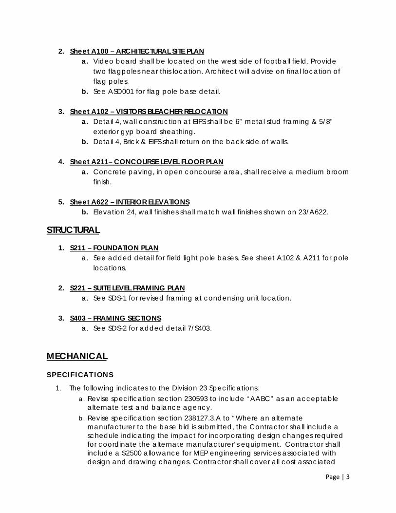
2. Sheet A100 – ARCHITECTURAL SITE PLAN a. Video board shall be located on the west side of football field. Provide
two flagpoles near this location. Architect will advise on final location of flag poles.
b. See ASD001 for flag pole base detail.
3. Sheet A102 – VISITORS BLEACHER RELOCATION a. Detail 4, wall construction at EIFS shall be 6” metal stud framing & 5/8”
exterior gyp board sheathing. b. Detail 4, Brick & EIFS shall return on the back side of walls.
4. Sheet A211– CONCOURSE LEVEL FLOOR PLAN
a. Concrete paving, in open concourse area, shall receive a medium broom finish.
5. Sheet A622 – INTERIOR ELEVATIONS b. Elevation 24, wall finishes shall match wall finishes shown on 23/A622.
STRUCTURAL
1. S211 – FOUNDATION PLAN a. See added detail for field light pole bases. See sheet A102 & A211 for pole
locations.
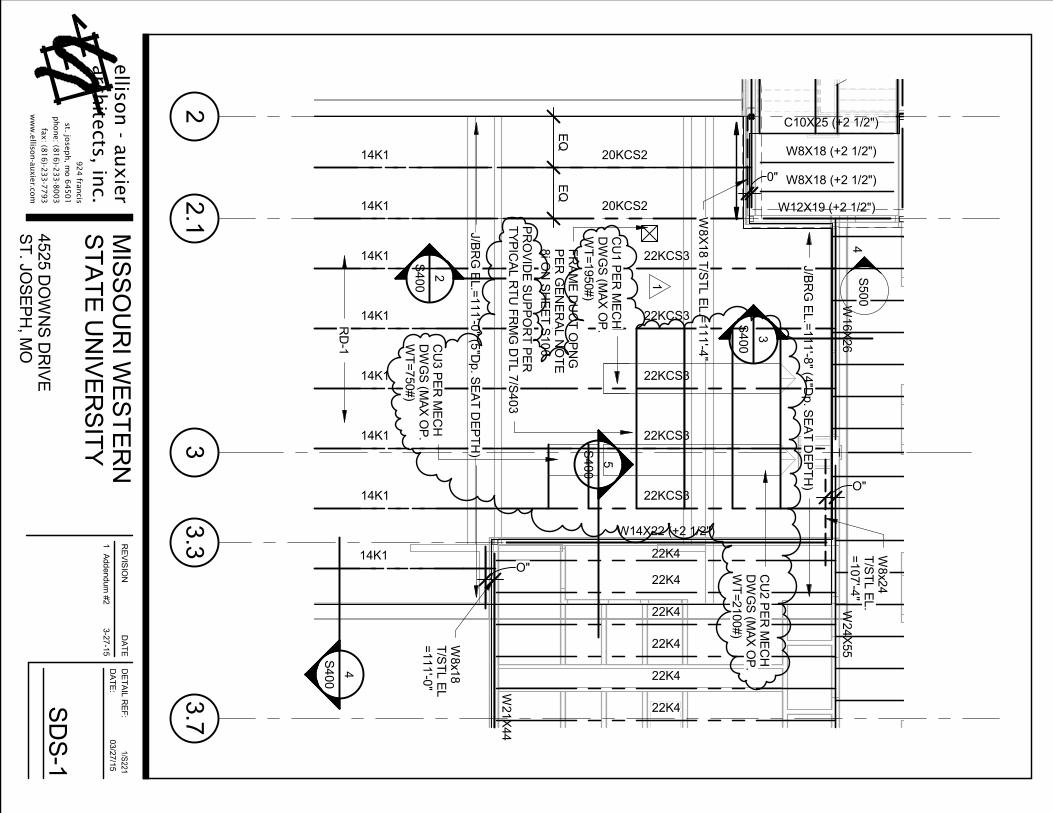
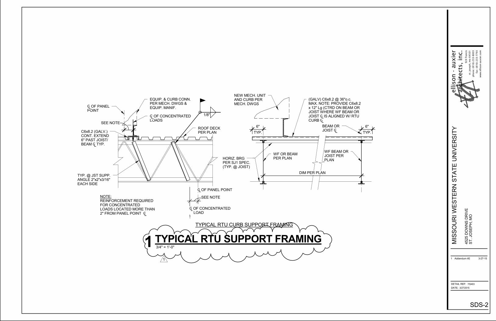
2. S221 – SUITE LEVEL FRAMING PLAN a. See SDS-1 for revised framing at condensing unit location.
3. S403 – FRAMING SECTIONS
a. See SDS-2 for added detail 7/S403.
MECHANICAL
SPECIFICATIONS
1. The following indicates to the Division 23 Specifications: a. Revise specification section 230593 to include “AABC” as an acceptable
alternate test and balance agency. b. Revise specification section 238127.3.A to “Where an alternate
manufacturer to the base bid is submitted, the Contractor shall include a schedule indicating the impact for incorporating design changes required for coordinate the alternate manufacturer’s equipment. Contractor shall include a $2500 allowance for MEP engineering services associated with design and drawing changes. Contractor shall cover all cost associated

Page | 4
with provided alternate manufacturer (i.e = additional structure, electrical modifications & etc.)”
DRAWINGS
M303 – MECHANICAL DETAILS
1. Revise mechanical “VRF Condensing Unit Roof Support” detail 4 with adding note for the support rails or structural supports shown are the responsibility of the mechanical contractor and to maintain all required clearance per manufacturer recommendations.
ELECTRICAL
1. E401 – ELECTRICAL ONE-LINE DIAGRAM
Revise note on one-line diagram for relocated field lighting to “ Provide new 4” conduit and conductors for the two relocated field lighting poles on home field side. Intercept and extend existing conduits and conductors for the two relocated field lighting poles on the visitors field side. Contractor to provide a fully functioning field lighting system including all required components.”
PLUMBING
1. No items
FIRE PROTECTION
1. No items
End of Addendum

Finish Schedule
Spratt Stadium Upgrades
Missouri Western State University
101 Tickets: Floor: Sealed Concrete
Base: Johnsonite 40 Black
Walls: SW 6120 Believable Buff
P.Lam Top: Formica 7812‐58 MDF Solidz
P.Lam Apron: Formica 5879‐58 Café Weft
102 Merchandise: Floor: Sealed Concrete
Base: Johnsonite 40 Black
Walls: SW 6381 Anjou Pear
103 Corridor: Floor: Sealed Concrete
Base: Johnsonite 40 Black
Walls: SW 6120 Believable Buff
104 Mechanical: Floor: Sealed Concrete
Base: Johnsonite 40 Black
Walls: SW 6120 Believable Buff
Walls: Slat Wall
105 Storage: Floor: Sealed Concrete
Base: Johnsonite 40 Black
Walls: SW 6120 Believable Buff
106 Janitor: Floor: Sealed Concrete
Base: Johnsonite 40 Black
Walls: SW 6120 Believable Buff
107 Men: Floor: Sealed Concrete
Base: Johnsonite 40 Black
Walls: SW 6120 Believable Buff
Walls: 6381 Anjou Pear
Partitions: TBD
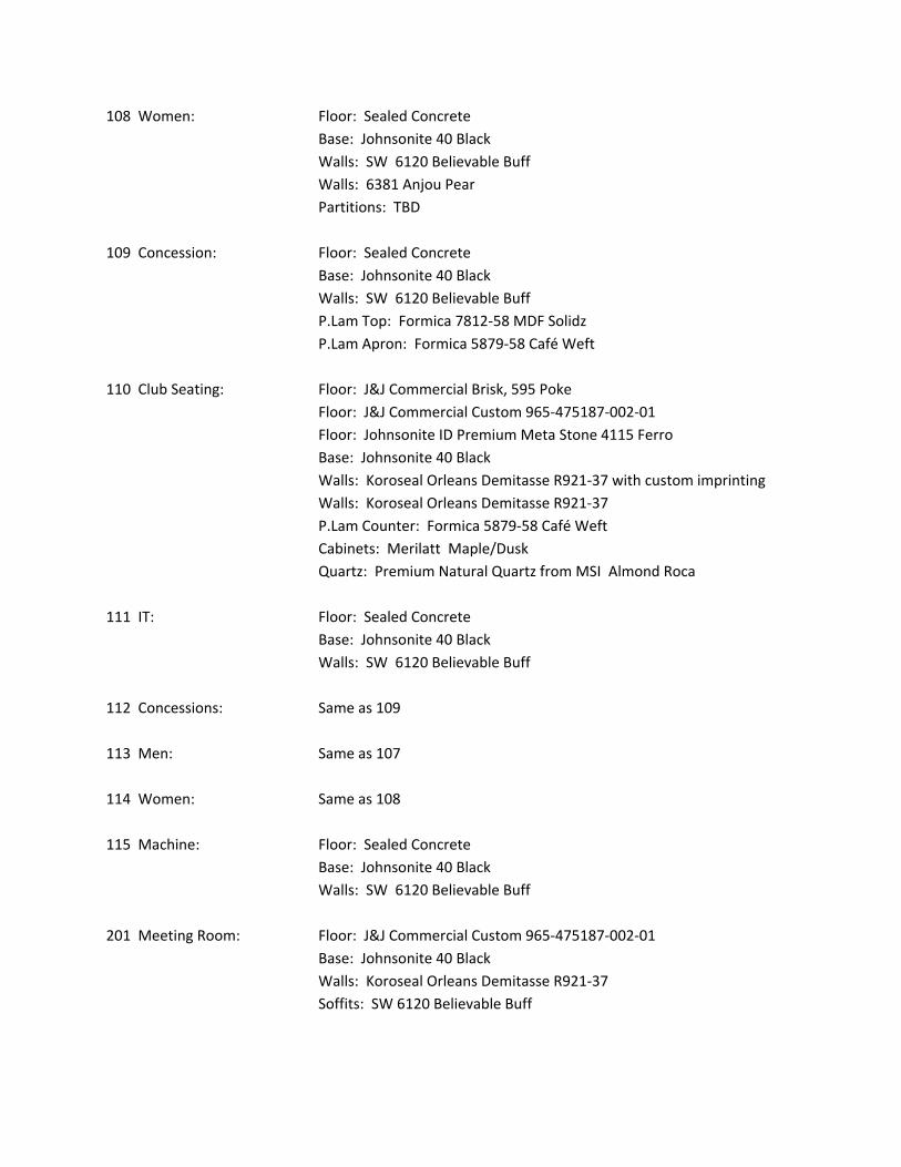
108 Women: Floor: Sealed Concrete
Base: Johnsonite 40 Black
Walls: SW 6120 Believable Buff
Walls: 6381 Anjou Pear
Partitions: TBD
109 Concession: Floor: Sealed Concrete
Base: Johnsonite 40 Black
Walls: SW 6120 Believable Buff
P.Lam Top: Formica 7812‐58 MDF Solidz
P.Lam Apron: Formica 5879‐58 Café Weft
110 Club Seating: Floor: J&J Commercial Brisk, 595 Poke
Floor: J&J Commercial Custom 965‐475187‐002‐01
Floor: Johnsonite ID Premium Meta Stone 4115 Ferro
Base: Johnsonite 40 Black
Walls: Koroseal Orleans Demitasse R921‐37 with custom imprinting
Walls: Koroseal Orleans Demitasse R921‐37
P.Lam Counter: Formica 5879‐58 Café Weft
Cabinets: Merilatt Maple/Dusk
Quartz: Premium Natural Quartz from MSI Almond Roca
111 IT: Floor: Sealed Concrete
Base: Johnsonite 40 Black
Walls: SW 6120 Believable Buff
112 Concessions: Same as 109
113 Men: Same as 107
114 Women: Same as 108
115 Machine: Floor: Sealed Concrete
Base: Johnsonite 40 Black
Walls: SW 6120 Believable Buff
201 Meeting Room: Floor: J&J Commercial Custom 965‐475187‐002‐01
Base: Johnsonite 40 Black
Walls: Koroseal Orleans Demitasse R921‐37
Soffits: SW 6120 Believable Buff
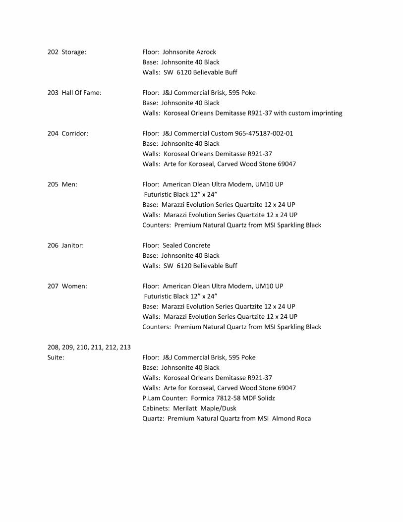
202 Storage: Floor: Johnsonite Azrock
Base: Johnsonite 40 Black
Walls: SW 6120 Believable Buff
203 Hall Of Fame: Floor: J&J Commercial Brisk, 595 Poke
Base: Johnsonite 40 Black
Walls: Koroseal Orleans Demitasse R921‐37 with custom imprinting
204 Corridor: Floor: J&J Commercial Custom 965‐475187‐002‐01
Base: Johnsonite 40 Black
Walls: Koroseal Orleans Demitasse R921‐37
Walls: Arte for Koroseal, Carved Wood Stone 69047
205 Men: Floor: American Olean Ultra Modern, UM10 UP
Futuristic Black 12” x 24”
Base: Marazzi Evolution Series Quartzite 12 x 24 UP
Walls: Marazzi Evolution Series Quartzite 12 x 24 UP
Counters: Premium Natural Quartz from MSI Sparkling Black
206 Janitor: Floor: Sealed Concrete
Base: Johnsonite 40 Black
Walls: SW 6120 Believable Buff
207 Women: Floor: American Olean Ultra Modern, UM10 UP
Futuristic Black 12” x 24”
Base: Marazzi Evolution Series Quartzite 12 x 24 UP
Walls: Marazzi Evolution Series Quartzite 12 x 24 UP
Counters: Premium Natural Quartz from MSI Sparkling Black
208, 209, 210, 211, 212, 213
Suite: Floor: J&J Commercial Brisk, 595 Poke
Base: Johnsonite 40 Black
Walls: Koroseal Orleans Demitasse R921‐37
Walls: Arte for Koroseal, Carved Wood Stone 69047
P.Lam Counter: Formica 7812‐58 MDF Solidz
Cabinets: Merilatt Maple/Dusk
Quartz: Premium Natural Quartz from MSI Almond Roca
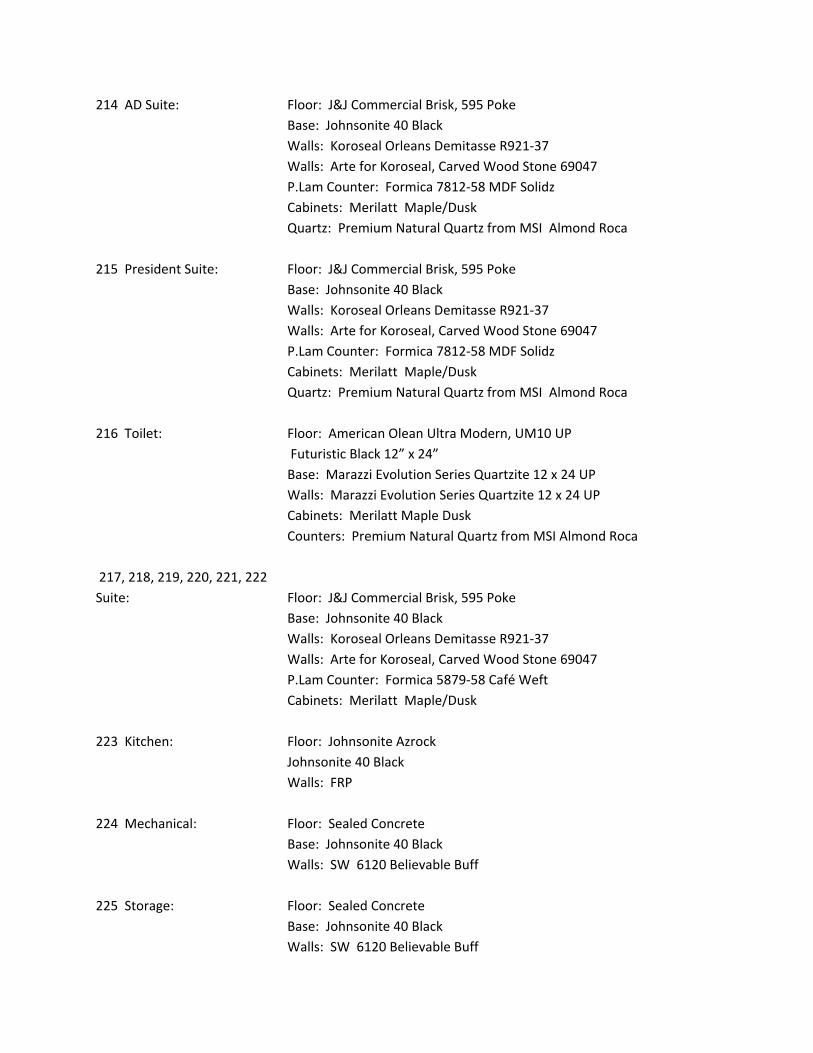
214 AD Suite: Floor: J&J Commercial Brisk, 595 Poke
Base: Johnsonite 40 Black
Walls: Koroseal Orleans Demitasse R921‐37
Walls: Arte for Koroseal, Carved Wood Stone 69047
P.Lam Counter: Formica 7812‐58 MDF Solidz
Cabinets: Merilatt Maple/Dusk
Quartz: Premium Natural Quartz from MSI Almond Roca
215 President Suite: Floor: J&J Commercial Brisk, 595 Poke
Base: Johnsonite 40 Black
Walls: Koroseal Orleans Demitasse R921‐37
Walls: Arte for Koroseal, Carved Wood Stone 69047
P.Lam Counter: Formica 7812‐58 MDF Solidz
Cabinets: Merilatt Maple/Dusk
Quartz: Premium Natural Quartz from MSI Almond Roca
216 Toilet: Floor: American Olean Ultra Modern, UM10 UP
Futuristic Black 12” x 24”
Base: Marazzi Evolution Series Quartzite 12 x 24 UP
Walls: Marazzi Evolution Series Quartzite 12 x 24 UP
Cabinets: Merilatt Maple Dusk
Counters: Premium Natural Quartz from MSI Almond Roca
217, 218, 219, 220, 221, 222
Suite: Floor: J&J Commercial Brisk, 595 Poke
Base: Johnsonite 40 Black
Walls: Koroseal Orleans Demitasse R921‐37
Walls: Arte for Koroseal, Carved Wood Stone 69047
P.Lam Counter: Formica 5879‐58 Café Weft
Cabinets: Merilatt Maple/Dusk
223 Kitchen: Floor: Johnsonite Azrock
Johnsonite 40 Black
Walls: FRP
224 Mechanical: Floor: Sealed Concrete
Base: Johnsonite 40 Black
Walls: SW 6120 Believable Buff
225 Storage: Floor: Sealed Concrete
Base: Johnsonite 40 Black
Walls: SW 6120 Believable Buff
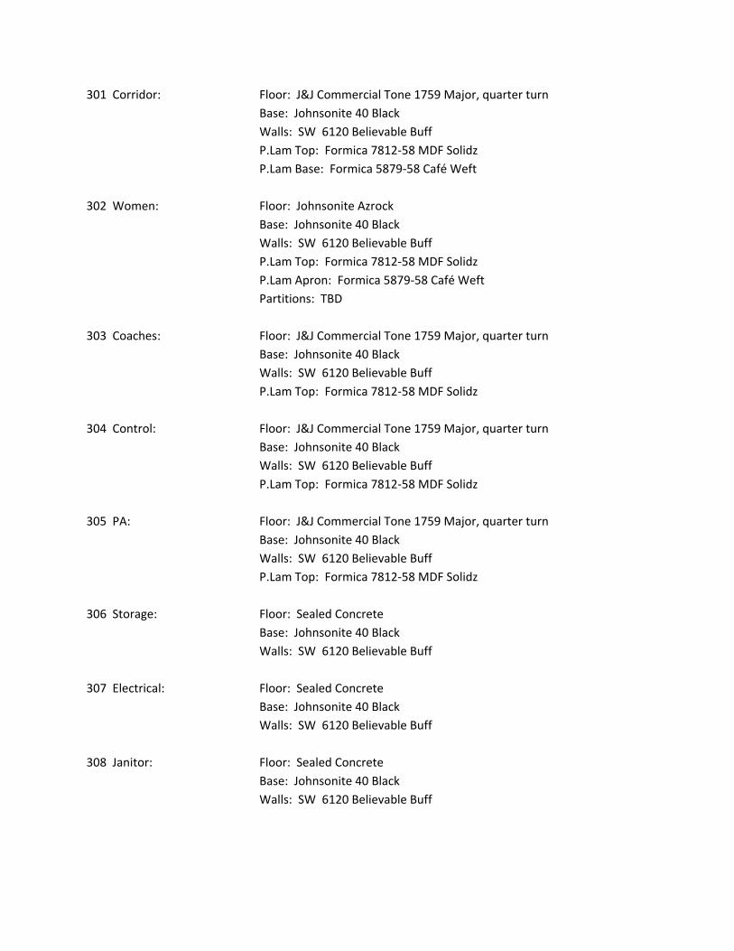
301 Corridor: Floor: J&J Commercial Tone 1759 Major, quarter turn
Base: Johnsonite 40 Black
Walls: SW 6120 Believable Buff
P.Lam Top: Formica 7812‐58 MDF Solidz
P.Lam Base: Formica 5879‐58 Café Weft
302 Women: Floor: Johnsonite Azrock
Base: Johnsonite 40 Black
Walls: SW 6120 Believable Buff
P.Lam Top: Formica 7812‐58 MDF Solidz
P.Lam Apron: Formica 5879‐58 Café Weft
Partitions: TBD
303 Coaches: Floor: J&J Commercial Tone 1759 Major, quarter turn
Base: Johnsonite 40 Black
Walls: SW 6120 Believable Buff
P.Lam Top: Formica 7812‐58 MDF Solidz
304 Control: Floor: J&J Commercial Tone 1759 Major, quarter turn
Base: Johnsonite 40 Black
Walls: SW 6120 Believable Buff
P.Lam Top: Formica 7812‐58 MDF Solidz
305 PA: Floor: J&J Commercial Tone 1759 Major, quarter turn
Base: Johnsonite 40 Black
Walls: SW 6120 Believable Buff
P.Lam Top: Formica 7812‐58 MDF Solidz
306 Storage: Floor: Sealed Concrete
Base: Johnsonite 40 Black
Walls: SW 6120 Believable Buff
307 Electrical: Floor: Sealed Concrete
Base: Johnsonite 40 Black
Walls: SW 6120 Believable Buff
308 Janitor: Floor: Sealed Concrete
Base: Johnsonite 40 Black
Walls: SW 6120 Believable Buff
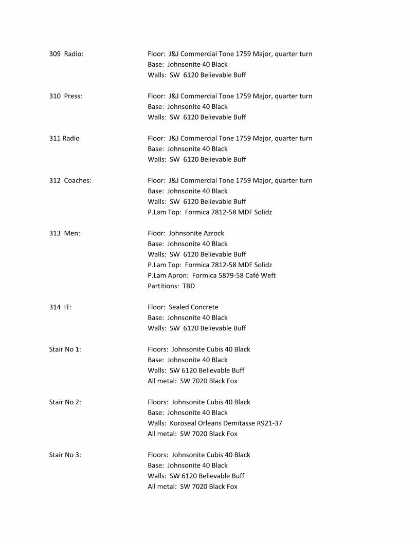
309 Radio: Floor: J&J Commercial Tone 1759 Major, quarter turn
Base: Johnsonite 40 Black
Walls: SW 6120 Believable Buff
310 Press: Floor: J&J Commercial Tone 1759 Major, quarter turn
Base: Johnsonite 40 Black
Walls: SW 6120 Believable Buff
311 Radio Floor: J&J Commercial Tone 1759 Major, quarter turn
Base: Johnsonite 40 Black
Walls: SW 6120 Believable Buff
312 Coaches: Floor: J&J Commercial Tone 1759 Major, quarter turn
Base: Johnsonite 40 Black
Walls: SW 6120 Believable Buff
P.Lam Top: Formica 7812‐58 MDF Solidz
313 Men: Floor: Johnsonite Azrock
Base: Johnsonite 40 Black
Walls: SW 6120 Believable Buff
P.Lam Top: Formica 7812‐58 MDF Solidz
P.Lam Apron: Formica 5879‐58 Café Weft
Partitions: TBD
314 IT: Floor: Sealed Concrete
Base: Johnsonite 40 Black
Walls: SW 6120 Believable Buff
Stair No 1: Floors: Johnsonite Cubis 40 Black
Base: Johnsonite 40 Black
Walls: SW 6120 Believable Buff
All metal: SW 7020 Black Fox
Stair No 2: Floors: Johnsonite Cubis 40 Black
Base: Johnsonite 40 Black
Walls: Koroseal Orleans Demitasse R921‐37
All metal: SW 7020 Black Fox
Stair No 3: Floors: Johnsonite Cubis 40 Black
Base: Johnsonite 40 Black
Walls: SW 6120 Believable Buff
All metal: SW 7020 Black Fox

Elev. 1 Floor: J&J Commercial Custom 965‐475187‐002‐01
Spratt Stadium UpgradesMissouri Western State University
10 7500 - 1 FLAGPOLES
SECTION 10 7500
FLAGPOLES
PART 1 GENERAL
1.01 SECTION INCLUDES
A. Aluminum Flagpoles.
1.02 REFERENCE STANDARDS
A. AASHTO M 36 - Standard Specification for Corrugated Steel Pipe, Metallic-Coated, for Sewersand Drains; American Association of State Highway and Transportation Officials; 2003.
B. ASTM B221 - Standard Specification for Aluminum and Aluminum-Alloy Extruded Bars, Rods,Wire, Profiles, and Tubes; 2012.
C. ASTM B221M - Standard Specification for Aluminum and Aluminum-Alloy Extruded Bars, Rods,Wire, Profiles, and Tubes [Metric]; 2012.
1.03 SUBMITTALS
A. See Section 01 3000 - Administrative Requirements, for submittal procedures.
B. Product Data: Provide data on pole, accessories, and configurations.
C. Shop Drawings: Indicate detailed dimensions, base details, anchor requirements, and imposedloads.
1.04 DELIVERY, STORAGE, AND HANDLING
A. Spiral wrap flagpole with protective covering and pack in protective shipping tubes orcontainers.
B. Protect flagpole and accessories from damage or moisture.
PART 2 PRODUCTS
2.01 MANUFACTURERS
A. Flagpoles:1. American Flagpole: www.americanflagpole.com.2. Concord Industries, Inc: www.concordindustries.com.3. Carrot-Top Industries; Product AH130.4. Substitutions: See Section 01 6000 - Product Requirements.
2.02 FLAGPOLES
A. Flagpoles: Aluminum.1. Design: Cone tapered.2. Mounting: Ground mounted type.3. Outside Butt Diameter: 5 inches.4. Outside Tip Diameter: 3 inches.5. Nominal Wall Thickness:.125 inches.6. Nominal Height: 30 ft & 25 ft; measured from nominal ground elevation.7. Halyard: External type .
B. Performance Requirements:1. Flagpole With Flag Flying: Resistant without permanent deformation to 90 miles/hr wind
velocity; non-resonant, safety design factor of 2.5.
2.03 POLE MATERIALS
A. Aluminum: ASTM B221 (ASTM B221M), 6063 alloy, T6 temper.
2.04 ACCESSORIES
A. Finial Ball: Stainless steel, 6 inch diameter.
B. Truck Assembly: Cast aluminum; revolving, stainless steel ball bearings, non-fouling.
C. Cleats: 9 inch size, aluminum with galvanized steel fastenings, two per halyard.

Spratt Stadium UpgradesMissouri Western State University
10 7500 - 2 FLAGPOLES
D. Cleat Box: Aluminum, with built-in hinge and hasp assembly, attached to pole with tamper proofscrews inside box.
E. Halyard: 5/16 inch diameter polypropylene, braided, white.
2.05 MOUNTING COMPONENTS
A. Foundation Tube Sleeve: AASHTO M 36M, corrugated 16 gage steel, galvanized, depth of 36min inches, as indicated.
B. Pole Base Attachment: Flush; steel base with base cover.
2.06 FINISHING
A. Metal Surfaces in Contact With Concrete: Asphaltic paint.
B. Aluminum: Mill finish..
C. Stainless Steel: No. 4 satin finish.
PART 3 EXECUTION
3.01 EXAMINATION
A. Verify that concrete foundation is ready to receive work and dimensions are as indicated onshop drawings.
3.02 INSTALLATION
A. Install flagpole, base assembly, and fittings in accordance with manufacturer's instructions.
3.03 ADJUSTING
A. Adjust operating devices so that halyard and flag function smoothly.
3.04 SCHEDULES
A. Building Flagpoles: one 30', one 25' as located on drawings.
END OF SECTION
Spratt Stadium UpgradesMissouri Western State University
12 2113 - 1 HORIZONTAL LOUVER BLINDS
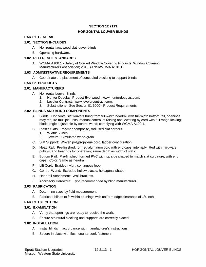
SECTION 12 2113
HORIZONTAL LOUVER BLINDS
PART 1 GENERAL
1.01 SECTION INCLUDES
A. Horizontal faux wood slat louver blinds.
B. Operating hardware.
1.02 REFERENCE STANDARDS
A. WCMA A100.1 - Safety of Corded Window Covering Products; Window CoveringManufacturers Association; 2010. (ANSI/WCMA A101.1)
1.03 ADMINISTRATIVE REQUIREMENTS
A. Coordinate the placement of concealed blocking to support blinds.
PART 2 PRODUCTS
2.01 MANUFACTURERS
A. Horizontal Louver Blinds:1. Hunter Douglas; Product Everwood: www.hunterdouglas.com.2. Levolor Contract: www.levolorcontract.com.3. Substitutions: See Section 01 6000 - Product Requirements.
2.02 BLINDS AND BLIND COMPONENTS
A. Blinds: Horizontal slat louvers hung from full-width headrail with full-width bottom rail, openingsmay require multiple units; manual control of raising and lowering by cord with full range locking;blade angle adjustable by control wand; complying with WCMA A100.1.
B. Plastic Slats: Polymer composite, radiused slat corners.1. Width: 2 inch.2. Texture: Simulated wood-grain.
C. Slat Support: Woven polypropylene cord, ladder configuration.
D. Head Rail: Pre-finished, formed aluminum box, with end caps; internally fitted with hardware,pulleys, and bearings for operation; same depth as width of slats
E. Bottom Rail: Pre-finished, formed PVC with top side shaped to match slat curvature; with endcaps. Color: Same as headrail.
F. Lift Cord: Braided nylon; continuous loop.
G. Control Wand: Extruded hollow plastic; hexagonal shape.
H. Headrail Attachment: Wall brackets.
I. Accessory Hardware: Type recommended by blind manufacturer.
2.03 FABRICATION
A. Determine sizes by field measurement.
B. Fabricate blinds to fit within openings with uniform edge clearance of 1/4 inch.
PART 3 EXECUTION
3.01 EXAMINATION
A. Verify that openings are ready to receive the work.
B. Ensure structural blocking and supports are correctly placed.
3.02 INSTALLATION
A. Install blinds in accordance with manufacturer's instructions.
B. Secure in place with flush countersunk fasteners.
Spratt Stadium UpgradesMissouri Western State University
12 2113 - 2 HORIZONTAL LOUVER BLINDS
3.03 INSTALLATION TOLERANCES
A. Maximum Variation of Gap at Window Opening Perimeter: 1/4 inch.
B. Maximum Offset From Level: 1/8 inch.
3.04 ADJUSTING
A. Adjust blinds for smooth operation.
3.05 CLEANING
A. Clean blind surfaces just prior to occupancy.
3.06 SCHEDULE
A. Main Floor Windows: Exterior windows in rooms 124, 103, 109. Interior windows in room 102.
END OF SECTION
2' - 6"5" DIA. FLAG POLE
FC-11 ALUM. FLASHING COLLAR
WATERPROOFING SEALANT
STEEL CENTERING WEDGES
CONCRETE BASE
FILL w/ PACKED DRY SAND
16 GA. 8" DIAMETER GALV. SLEEVE
12" x 12" BASE PLATE WELDEDTO SLEEVE
3/4" DIA. GROUND SPIKE18" LONG MIN.
VE
RIF
Y w
/ MA
NU
F.
1' -
2"
2' - 4"
REVISION DATE DETAIL REF:
DATE:ellison - auxierarchitects, inc.
www.ellison-auxier.comfax: (816)-233-7793
phone: (816)-233-8003
st. joseph, mo 64501
924 francis
MISSOURI WESTERNSTATE UNIVERSITY
4525 DOWNS DRIVEST. JOSEPH, MO
FLAG POLEBASE
ASD001
03/27/15
SCALE: 1" = 1'-0"1FLAG POLE BASE
23
3.3
20KCS2
20KCS2
22KCS3
22KCS3
22KCS3
22KCS3
22KCS3
14K1
14K1
14K1
14K1
14K1
14K1
14K1
14K1
RD
-1
J/B
RG
EL.=
111'-8
" (4"D
p. S
EA
T D
EP
TH
)
J/B
RG
EL.=
111'-0
" (5"D
p. S
EA
T D
EP
TH
)
W21X
44
W14X22 (+2 1/2")
22K4
22K4
22K4
22K4
22K4
22K4
W12X19 (+2 1/2")
2.1
C10X25 (+2 1/2")
W8X18 (+2 1/2")
W8X18 (+2 1/2")
3.7
W24X
55
2
S400
3
S400
5
S400
S500
4W
16X
26
W8x1
8T
/ST
L E
L=
111'-0
"
O"
W8x2
4T
/ST
L E
L.
=107'-4
"
O"F
RA
ME
DU
CT
OP
NG
PE
R G
EN
ER
AL N
OT
E8i O
N S
HE
ET
S100
EQ
EQ
CU
2 P
ER
ME
CH
DW
GS
(MA
X O
P.
WT
=2100#)
CU
1 P
ER
ME
CH
DW
GS
(MA
X O
P.
WT
=1950#)
W8X
18 T
/ST
L E
L.=
111'-4
"
4"0"
4
S400
CU
3 P
ER
ME
CH
DW
GS
(MA
X O
P.
WT
=750#)
PR
OV
IDE
SU
PP
OR
T P
ER
TY
PIC
AL R
TU
FR
MG
DT
L 7
/S403
1
RE
VIS
ION
DA
TE
DE
TA
IL R
EF
:
DA
TE
:ellis
on - a
uxie
rarc
hite
cts
, inc.
ww
w.e
llison-a
uxie
r.com
fax: (8
16
)-233
-77
93
pho
ne: (8
16
)-233
-80
03
st. jo
sep
h, m
o 6
450
1
92
4 fra
ncis
1A
dd
end
um
#2
3-2
7-1
5M
ISS
OU
RI W
ES
TE
RN
ST
AT
E U
NIV
ER
SIT
Y
4525 D
OW
NS
DR
IVE
ST
. JO
SE
PH
, MO
SD
S-1
03/2
7/1
5
1/S
22
1
SEE NOTE
C OF CONCENTRATED LOAD
C OF PANEL POINT
1/8"
TYP. @ JST SUPP.ANGLE 2"x2"x3/16"EACH SIDE
NOTE:REINFORCEMENT REQUIREDFOR CONCENTRATEDLOADS LOCATED MORE THAN2" FROM PANEL POINT CL
L
L
ROOF DECKPER PLAN
EQUIP. & CURB CONN.PER MECH. DWGS &EQUIP. MANIF.
C OF CONCENTRATEDLOADS
C OF PANELPOINT
C6x8.2 (GALV.)CONT. EXTEND6" PAST JOIST/BEAM C TYP.
L
L
L
SEE NOTE
TYP.
6"
TYP.
6"
NEW MECH. UNITAND CURB PERMECH. DWGS
(GALV) C6x8.2 @ 36"o.c.MAX. NOTE: PROVIDE C6x8.2x 12" Lg (CTRD ON BEAM ORJOIST WHERE WF BEAM ORJOIST C IS ALIGNED W/ RTUCURB CL
L
BEAM ORJOIST CL
WF OR BEAMPER PLAN
WF BEAM ORJOIST PERPLAN
DIM PER PLAN
TYPICAL RTU CURB SUPPORT FRAMING
HORIZ. BRGPER SJ1 SPEC.(TYP. @ JOIST)
ellis
on -
auxie
rarc
hit
ects
, in
c.
ww
w.e
llis
on-a
uxie
r.com
fax: (8
16
)-23
3-7
79
3
phone: (8
16)-
23
3-8
00
3
st.
joseph, m
o 6
45
01
92
4 f
rancis
DETAIL REF:
DATE:
1 Addendum #2 3-27-15
MIS
SO
UR
I W
ES
TE
RN
ST
AT
E U
NIV
ER
SIT
Y
4525 D
OW
NS
DR
IVE
ST
. JO
SE
PH
, M
O
SDS-2
3/4" = 1'-0"1 TYPICAL RTU SUPPORT FRAMING
1
7/S403
3/27/2015

GRIF
FON
SGRIF
FON
S
2010 30
MISSOURI WESTERNMISSOURI WESTERN
40 50 40 30 20 102010 30 40 50 40 30 20 10
CRAIG FIELD
I I I I I I I I I I I I I I I I I I I I I I I I I I I I I I I I I I I I I I I I I I I I I I I I I I I I I I I I I I I I I I I I I I I I I I I I I I I I I I I I
I I I I I I I I I I I I I I I I I I I I I I I I I I I I I I I I I I I I I I I I I I I I I I I I I I I I I I I I I I I I I I I I I I I I I I I I I I I I I I I I
I
I I I I I I I I I I I I I I I I I I I I I I I I I I I I I I I I I I I I I I I I I I I I I I I I I I I I I I I I I I I I I I I I I I I I I I I I I I I I
I I I II I I II I I II I I II I I II I I II I I II I I II I I II I I II I I II I I II I I II I I II I I II I I II I I II I I II I I II I I I
I I I I
I
13' -
11
3/32
"14
' - 0
29/
32"
132'
- 0
"
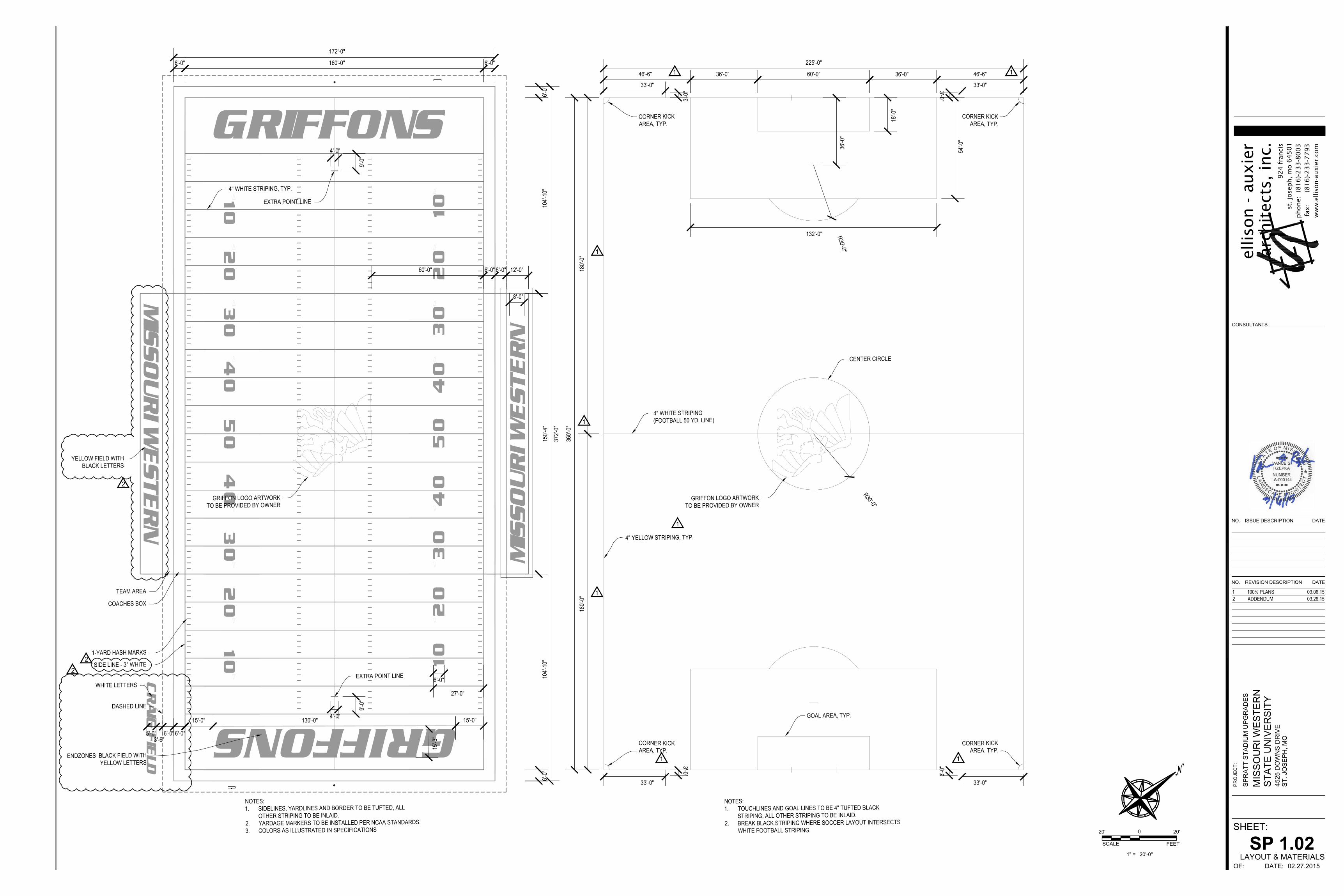
GRIFFONS
MIS
SOURI W
ESTERN
MIS
SOURI W
ESTERN
CRAIG
FIE
LD
SHEET:
PRO
JEC
T:
OF: DATE:
NO. ISSUE DESCRIPTION DATE
NO. REVISION DESCRIPTION DATE
CONSULTANTS
924 f
ranci
sst
. jo
seph, m
o 6
4501
phone:
(8
16)-
233-8
003
fax: (
816)-
233-7
793
ww
w.e
llis
on-a
uxie
r.co
m
arch
itec
ts, in
c.el
liso
n -
auxie
r
02.27.2015
SPR
ATT
STAD
IUM
UPG
RAD
ES
4525
DO
WN
S D
RIV
EST
. JO
SEPH
, MO
MIS
SOU
RI W
ESTE
RN
STAT
E U
NIV
ERSI
TY
SP 1.02LAYOUT & MATERIALS
SCALE
1" =
0
FEET
20'-0"
20' 20'
1
1
1
1
1 1
11
2
22