Embed Size (px)
Citation preview
Page 1 of 3
ADDENDUM NO. 02 TO: PLANS AND SPECIFICATIONS FOR STATE OF MISSOURI
Interior and Exterior Repairs and Improvements Missouri State Highway Patrol Hangar Jefferson City Memorial Airport, Missouri Project No.: R2007-01
Bid Opening Date: 1:30 PM, Thursday February 13, 2020 (Not Changed)
Bidders are hereby informed that the construction Plans and/or Specifications are modified as follows: PROCUREMENT AND CONTRACTING INFORMATION CHANGES:
1. Section 00 2113 – Instructions To Bidders:
a. Article 14.0, Section B.1. (Bottom of page 6 of 8): DELETE: “an MBE or WBE must be certified by the State of Missouri, Office of Equal Opportunity and”. This is to allow MBE, WBE, or MBE/WBE to have ample time to register with the Office of Equal Opportunity; this requirement will not take effect until July 1, 2020.
2. Section 00 7300 – Supplementary Conditions:
a. 2.0 Contacts: REVISE Construction Representative mailing address, phone and fax as follows:
i. 709 Missouri Blvd., Jefferson City, MO 65109 ii. Telephone: 573.751.6517; Fax: 573.522.1763
SPECIFICATION CHANGES:
1. Section 01 2200-Unit Prices: a. REVISE 3.1 List of Unit Prices, item A.3. to read as follows:
Base Bid Quantity: 5,220 square feet of application area.
2. Section 01 2300-Alternates: a. REVISE 3.1 Schedule of Alternates, B. Alternate No. 2: to read as follows:
B. Alternate No. 2: Remove existing epoxy floor coating throughout the hangar area/s and replace with new epoxy floor coating. See Section 09 6700 Fluid-Applied Flooring. See Section 09 0561 Common Work Results for Flooring Preparation for testing, and remedial coatings for the concrete slab. See D-101 note 26 and A-100 note 15 for scope limits. If the Alternate bid is accepted, the allowance indicated in Section 012100 - Allowances will not be utilized for the project. The Alternate 2 bid value listed on the bid form should include the reduction of the $5,000 allowance in the base bid for epoxy floor cleaning and patching. E.g. Cost for Alternate 2 scope of work minus $5,000 allowance in base bid = Alternate 2 bid value indicated on the bid form.
Page 2 of 3
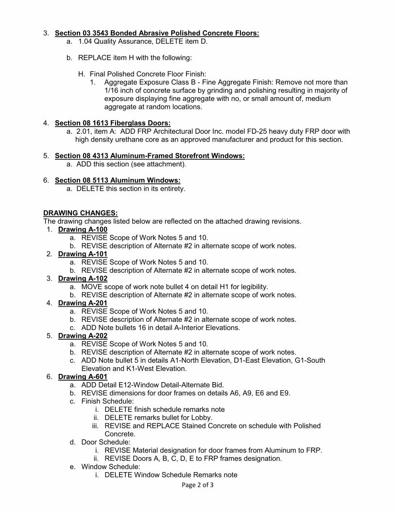
3. Section 03 3543 Bonded Abrasive Polished Concrete Floors: a. 1.04 Quality Assurance, DELETE item D.
b. REPLACE item H with the following:
H. Final Polished Concrete Floor Finish:
1. Aggregate Exposure Class B - Fine Aggregate Finish: Remove not more than 1/16 inch of concrete surface by grinding and polishing resulting in majority of exposure displaying fine aggregate with no, or small amount of, medium aggregate at random locations.
4. Section 08 1613 Fiberglass Doors:
a. 2.01, item A: ADD FRP Architectural Door Inc. model FD-25 heavy duty FRP door with high density urethane core as an approved manufacturer and product for this section.
5. Section 08 4313 Aluminum-Framed Storefront Windows:
a. ADD this section (see attachment). 6. Section 08 5113 Aluminum Windows:
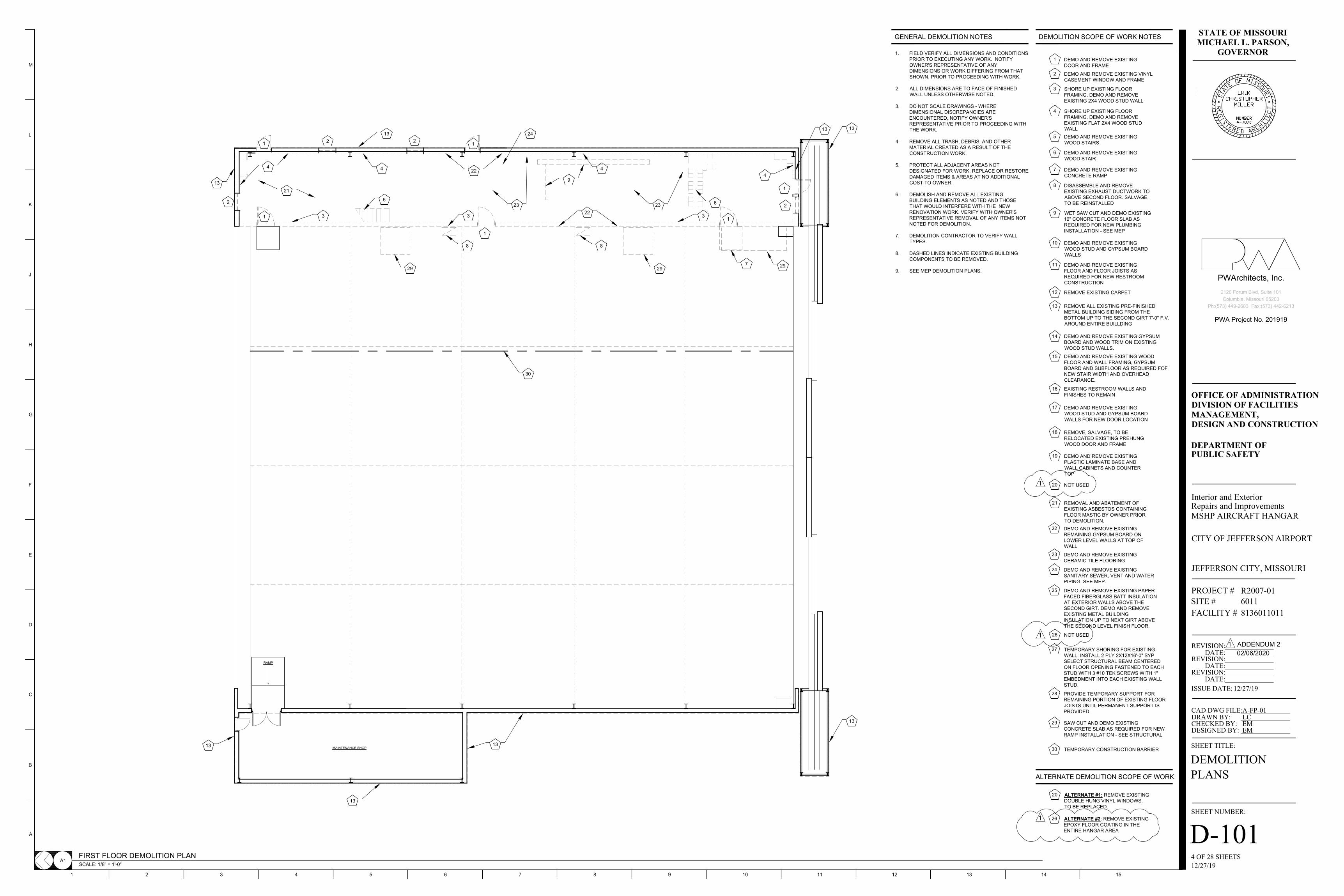
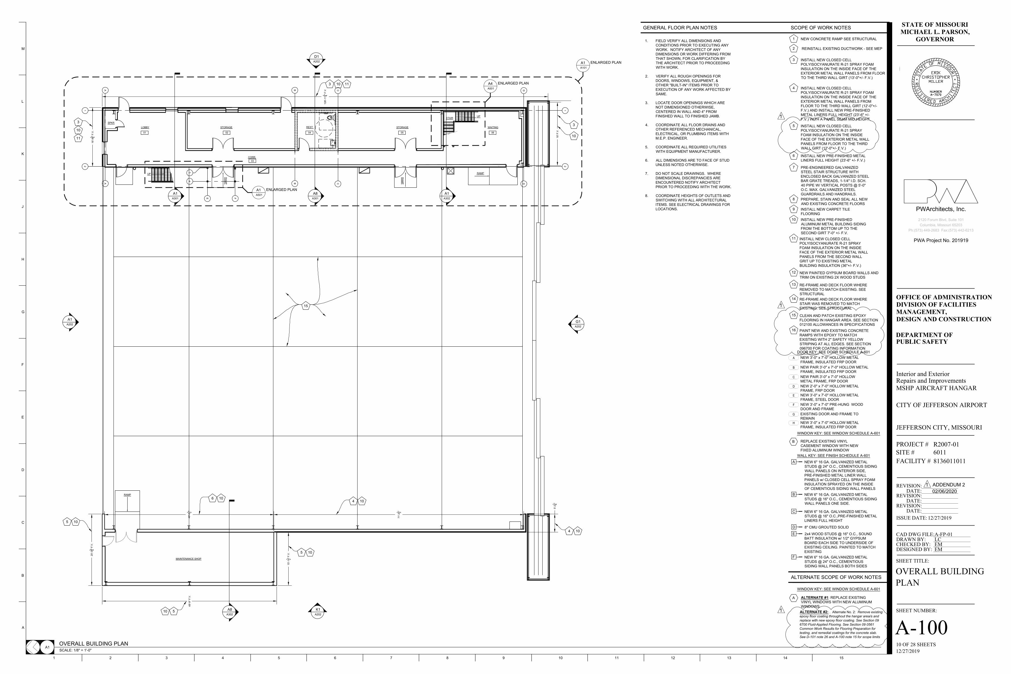
a. DELETE this section in its entirety. DRAWING CHANGES: The drawing changes listed below are reflected on the attached drawing revisions. 1. Drawing A-100
a. REVISE Scope of Work Notes 5 and 10. b. REVISE description of Alternate #2 in alternate scope of work notes.
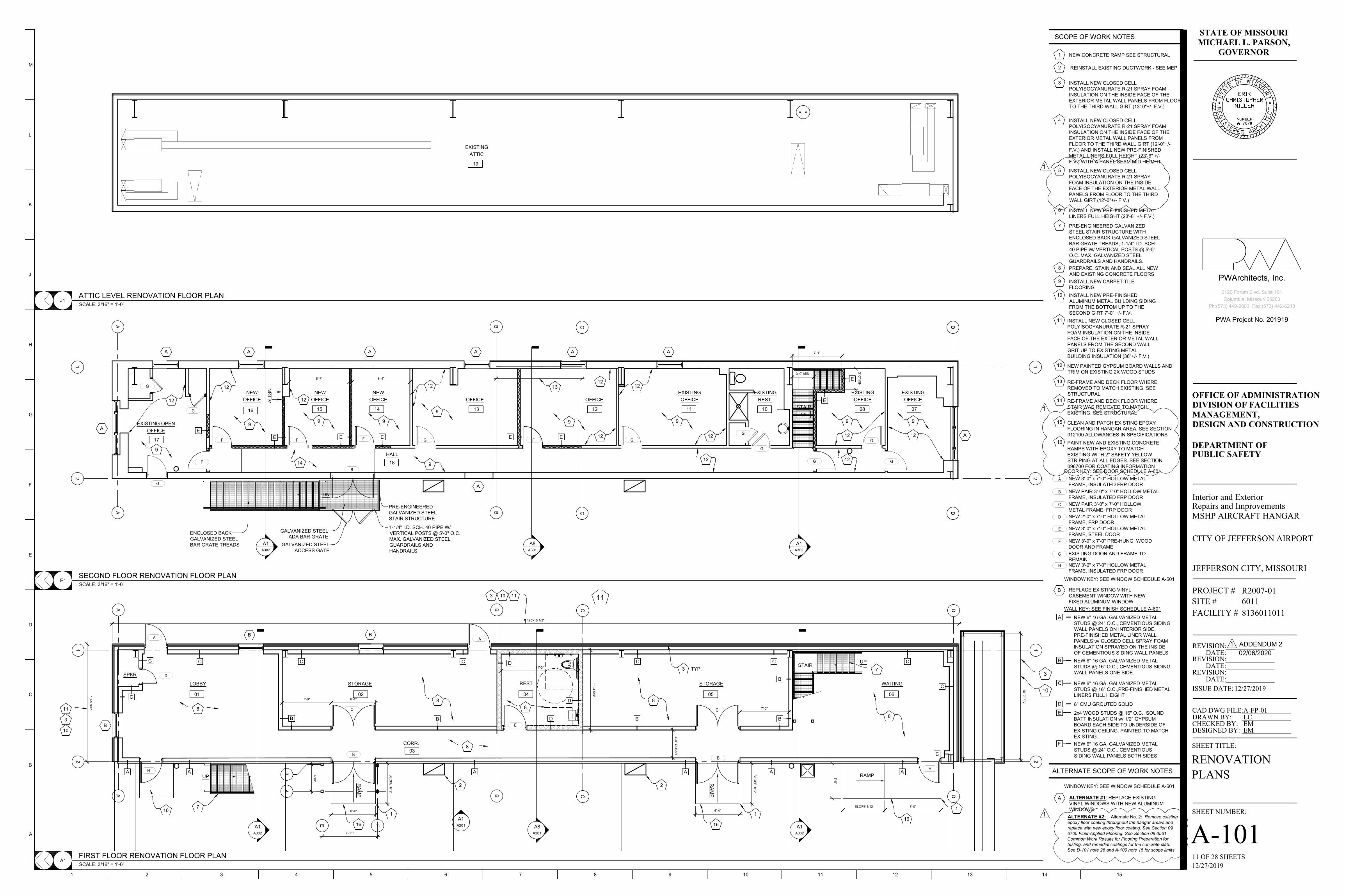
2. Drawing A-101 a. REVISE Scope of Work Notes 5 and 10. b. REVISE description of Alternate #2 in alternate scope of work notes.
3. Drawing A-102 a. MOVE scope of work note bullet 4 on detail H1 for legibility. b. REVISE description of Alternate #2 in alternate scope of work notes.
4. Drawing A-201 a. REVISE Scope of Work Notes 5 and 10. b. REVISE description of Alternate #2 in alternate scope of work notes. c. ADD Note bullets 16 in detail A-Interior Elevations.
5. Drawing A-202 a. REVISE Scope of Work Notes 5 and 10. b. REVISE description of Alternate #2 in alternate scope of work notes. c. ADD Note bullet 5 in details A1-North Elevation, D1-East Elevation, G1-South
Elevation and K1-West Elevation. 6. Drawing A-601
a. ADD Detail E12-Window Detail-Alternate Bid. b. REVISE dimensions for door frames on details A6, A9, E6 and E9. c. Finish Schedule:
i. DELETE finish schedule remarks note ii. DELETE remarks bullet for Lobby. iii. REVISE and REPLACE Stained Concrete on schedule with Polished
Concrete. d. Door Schedule:
i. REVISE Material designation for door frames from Aluminum to FRP. ii. REVISE Doors A, B, C, D, E to FRP frames designation.
e. Window Schedule: i. DELETE Window Schedule Remarks note
Page 3 of 3
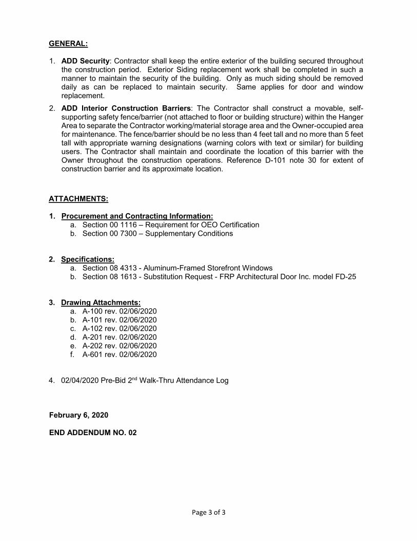
GENERAL:
1. ADD Security: Contractor shall keep the entire exterior of the building secured throughout
the construction period. Exterior Siding replacement work shall be completed in such a manner to maintain the security of the building. Only as much siding should be removed daily as can be replaced to maintain security. Same applies for door and window replacement.
2. ADD Interior Construction Barriers: The Contractor shall construct a movable, self-supporting safety fence/barrier (not attached to floor or building structure) within the Hanger Area to separate the Contractor working/material storage area and the Owner-occupied area for maintenance. The fence/barrier should be no less than 4 feet tall and no more than 5 feet tall with appropriate warning designations (warning colors with text or similar) for building users. The Contractor shall maintain and coordinate the location of this barrier with the Owner throughout the construction operations. Reference D-101 note 30 for extent of construction barrier and its approximate location.
ATTACHMENTS:
1. Procurement and Contracting Information:
a. Section 00 1116 – Requirement for OEO Certification b. Section 00 7300 – Supplementary Conditions
2. Specifications: a. Section 08 4313 - Aluminum-Framed Storefront Windows b. Section 08 1613 - Substitution Request - FRP Architectural Door Inc. model FD-25
3. Drawing Attachments: a. A-100 rev. 02/06/2020 b. A-101 rev. 02/06/2020 c. A-102 rev. 02/06/2020 d. A-201 rev. 02/06/2020 e. A-202 rev. 02/06/2020 f. A-601 rev. 02/06/2020
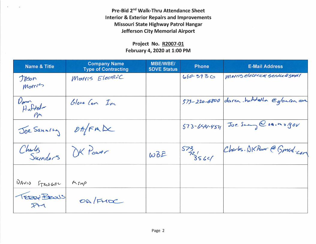
4. 02/04/2020 Pre-Bid 2nd Walk-Thru Attendance Log
February 6, 2020 END ADDENDUM NO. 02


SECTION 007300 - SUPPLEMENTARY CONDITIONS 1.0 GENERAL:
A. These Supplementary General Conditions clarify, add, delete, or otherwise modify standard terms and conditions of DIVISION 0, BIDDING AND CONTRACTING REQUIREMENTS.
2.0 CONTACTS:
Designer: Erik Miller, AIA PWArchitects, Inc. 2120 Forum Blvd., Ste. 101 Columbia, MO 65203 Telephone: 573-449-2683; Fax: 573-442-6213 Email: [email protected]
Construction Representative: Joe Sanning Division of Facilities Management, Design and Construction 709 Missouri Blvd., Jefferson City, MO 65109 Telephone: 573.751.6517; Fax: 573.522.1763 Email: [email protected]
Project Manager: Terry Bruns Division of Facilities Management, Design and Construction 301 West High Street, Room 730 Jefferson City, Missouri 65102 Telephone: 573-526-5184; Fax: 573-751-7277 Email: [email protected]
Contract Specialist: Drew Henrickson Division of Facilities Management, Design and Construction 301 West High Street, Room 730 Jefferson City, Missouri 65102 Telephone: 573-751-8128; Fax: 573-751-7277 Email: [email protected]
3.0 NOTICE: ALL BID MATERIALS ARE DUE AT THE TIME OF BID SUBMITTAL. THERE IS
NO SECOND SUBMITTAL FOR THIS PROJECT.
4.0 FURNISHING CONSTRUCTION DOCUMENTS: A. The Owner will furnish the Contractor with approximately 5 complete sets of drawings and
specifications at no charge. B. The Owner will furnish the Contractor with approximately 5 sets of explanatory or change drawings at
no charge. C. The Contractor may make copies of the documents as needed with no additional cost to the Owner.
5.0 ILLEGAL IMMIGRATION REFORM AND IMMIGRANT RESPONSIBILITY ACT
The Contractor understands and agrees that by signing a contract for this project, they certify the following: A. The Contractor shall only utilize personnel authorized to work in the United States in accordance with
applicable federal and state laws. This includes but is not limited to the Illegal Immigration Reform and Immigrant Responsibility Act (IIRIRA) and INA Section 274A.
B. If the Contractor is found to be in violation of this requirement or the applicable laws of the state, federal and local laws and regulations, and if the State of Missouri has reasonable cause to believe that the Contractor has knowingly employed individuals who are not eligible to work in the United States, the state shall have the right to cancel the contract immediately without penalty or recourse and suspend or debar the contractor from doing business with the state.
C. The Contractor agrees to fully cooperate with any audit or investigation from federal, state or local law enforcement agencies.
6.0 SAFETY REQUIREMENTS
Contractor and subcontractors at any tier shall comply with RSMo 292.675 and Article 1.3, E, of Section 007213, General Conditions.
SECTION 007300 – SUPPLEMENTARY CONDITIONS 07/16 Page 1 of 1

Interior and Exterior Repairs andImprovementsMissouri State Highway Patrol Hangar
Project # R2007-01 08 4313/1ALUMINUM-FRAMED
STOREFRONTS
SECTION 08 4313ALUMINUM-FRAMED STOREFRONT WINDOWS
PART 1 GENERAL1.01 RELATED DOCUMENTS
A. Drawings and general provisions of the Contract including General and SupplementaryConditions and Division 1 Specification Sections apply to this Section.
B. See Section 012300-Alternates. Aluminum Windows for the Upper Level are an Alternate Biditem.
1.02 SECTION INCLUDESA. Aluminum-framed storefront windows, with vision glass.B. Weatherstripping.C. Perimeter sealant specified in Section 07 90 05, Joint Sealers.
1.03 ADMINISTRATIVE REQUIREMENTSA. Coordinate with installation of other components that comprise the exterior enclosure.B. Preinstallation Meeting: Conduct a preinstallation meeting one week before starting work of this
section; require attendance by all affected installers.1.04 SUBMITTALS
A. See Division One for submittal procedures.B. Product Data: Provide component dimensions, describe components within assembly,
anchorage and fasteners, glass, internal drainage details.C. Shop Drawings: Indicate system dimensions, framed opening requirements and tolerances,
affected related Work, expansion and contraction joint location and details, and field weldingrequired.
D. Design Data: Provide framing member structural and physical characteristics, engineeringcalculations, dimensional limitations.
E. Hardware Schedule: Complete itemization of each item of hardware to be provided for eachdoor, cross-referenced to door identification numbers in Contract Documents.
F. Manufacturer's Certificate: Certify that the products supplied meet or exceed the specifiedrequirements.
G. Report of field testing for water leakage.H. Warranty: Submit manufacturer warranty and ensure forms have been completed in Owner's
name and registered with manufacturer.1.05 QUALITY ASSURANCE
A. Designer Qualifications: Design structural support framing components under direct supervisionof a Professional Structural Engineer experienced in design of this Work and licensed at theState in which the Project is located.
B. Manufacturer and Installer Qualifications: Company specializing in manufacturing aluminumglazing systems with minimum three years of documented experience.
1.06 DELIVERY, STORAGE, AND HANDLINGA. Handle products of this section in accordance with AAMA CW-10.B. Protect finished aluminum surfaces with wrapping. Do not use adhesive papers or sprayed
coatings that bond to aluminum when exposed to sunlight or weather.
Interior and Exterior Repairs andImprovementsMissouri State Highway Patrol Hangar
Project # R2007-01 08 4313/2ALUMINUM-FRAMED
STOREFRONT WINDOWS
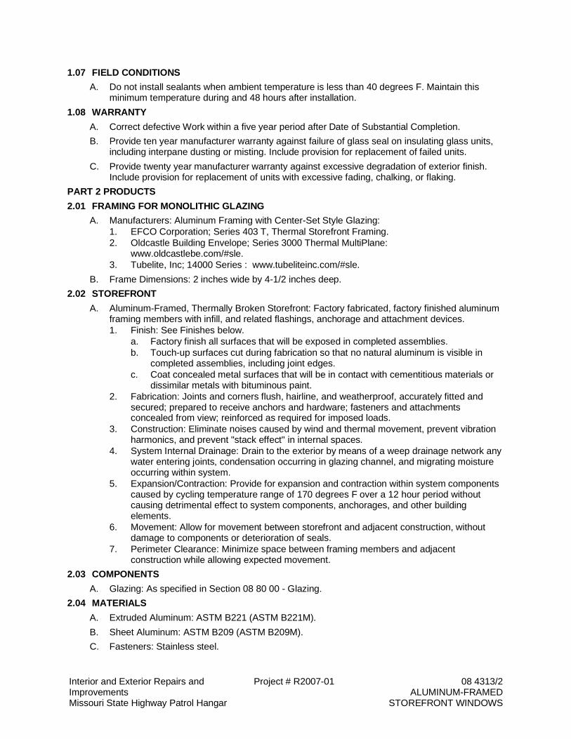
1.07 FIELD CONDITIONSA. Do not install sealants when ambient temperature is less than 40 degrees F. Maintain this
minimum temperature during and 48 hours after installation.1.08 WARRANTY
A. Correct defective Work within a five year period after Date of Substantial Completion.B. Provide ten year manufacturer warranty against failure of glass seal on insulating glass units,
including interpane dusting or misting. Include provision for replacement of failed units.C. Provide twenty year manufacturer warranty against excessive degradation of exterior finish.
Include provision for replacement of units with excessive fading, chalking, or flaking.PART 2 PRODUCTS2.01 FRAMING FOR MONOLITHIC GLAZING
A. Manufacturers: Aluminum Framing with Center-Set Style Glazing:1. EFCO Corporation; Series 403 T, Thermal Storefront Framing.2. Oldcastle Building Envelope; Series 3000 Thermal MultiPlane:
www.oldcastlebe.com/#sle.3. Tubelite, Inc; 14000 Series : www.tubeliteinc.com/#sle.
B. Frame Dimensions: 2 inches wide by 4-1/2 inches deep.2.02 STOREFRONT
A. Aluminum-Framed, Thermally Broken Storefront: Factory fabricated, factory finished aluminumframing members with infill, and related flashings, anchorage and attachment devices.1. Finish: See Finishes below.
a. Factory finish all surfaces that will be exposed in completed assemblies.b. Touch-up surfaces cut during fabrication so that no natural aluminum is visible in
completed assemblies, including joint edges.c. Coat concealed metal surfaces that will be in contact with cementitious materials or
dissimilar metals with bituminous paint.2. Fabrication: Joints and corners flush, hairline, and weatherproof, accurately fitted and
secured; prepared to receive anchors and hardware; fasteners and attachmentsconcealed from view; reinforced as required for imposed loads.
3. Construction: Eliminate noises caused by wind and thermal movement, prevent vibrationharmonics, and prevent "stack effect" in internal spaces.
4. System Internal Drainage: Drain to the exterior by means of a weep drainage network anywater entering joints, condensation occurring in glazing channel, and migrating moistureoccurring within system.
5. Expansion/Contraction: Provide for expansion and contraction within system componentscaused by cycling temperature range of 170 degrees F over a 12 hour period withoutcausing detrimental effect to system components, anchorages, and other buildingelements.
6. Movement: Allow for movement between storefront and adjacent construction, withoutdamage to components or deterioration of seals.
7. Perimeter Clearance: Minimize space between framing members and adjacentconstruction while allowing expected movement.
2.03 COMPONENTSA. Glazing: As specified in Section 08 80 00 - Glazing.
2.04 MATERIALSA. Extruded Aluminum: ASTM B221 (ASTM B221M).B. Sheet Aluminum: ASTM B209 (ASTM B209M).C. Fasteners: Stainless steel.
Interior and Exterior Repairs andImprovementsMissouri State Highway Patrol Hangar
Project # R2007-01 08 4313/3ALUMINUM-FRAMED
STOREFRONT WINDOWS
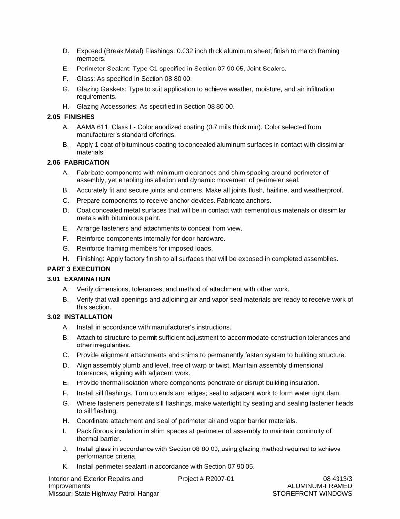
D. Exposed (Break Metal) Flashings: 0.032 inch thick aluminum sheet; finish to match framingmembers.
E. Perimeter Sealant: Type G1 specified in Section 07 90 05, Joint Sealers.F. Glass: As specified in Section 08 80 00.G. Glazing Gaskets: Type to suit application to achieve weather, moisture, and air infiltration
requirements.H. Glazing Accessories: As specified in Section 08 80 00.
2.05 FINISHESA. AAMA 611, Class I - Color anodized coating (0.7 mils thick min). Color selected from
manufacturer's standard offerings.B. Apply 1 coat of bituminous coating to concealed aluminum surfaces in contact with dissimilar
materials.2.06 FABRICATION
A. Fabricate components with minimum clearances and shim spacing around perimeter ofassembly, yet enabling installation and dynamic movement of perimeter seal.
B. Accurately fit and secure joints and corners. Make all joints flush, hairline, and weatherproof.C. Prepare components to receive anchor devices. Fabricate anchors.D. Coat concealed metal surfaces that will be in contact with cementitious materials or dissimilar
metals with bituminous paint.E. Arrange fasteners and attachments to conceal from view.F. Reinforce components internally for door hardware.G. Reinforce framing members for imposed loads.H. Finishing: Apply factory finish to all surfaces that will be exposed in completed assemblies.
PART 3 EXECUTION3.01 EXAMINATION
A. Verify dimensions, tolerances, and method of attachment with other work.B. Verify that wall openings and adjoining air and vapor seal materials are ready to receive work of
this section.3.02 INSTALLATION
A. Install in accordance with manufacturer's instructions.B. Attach to structure to permit sufficient adjustment to accommodate construction tolerances and
other irregularities.C. Provide alignment attachments and shims to permanently fasten system to building structure.D. Align assembly plumb and level, free of warp or twist. Maintain assembly dimensional
tolerances, aligning with adjacent work.E. Provide thermal isolation where components penetrate or disrupt building insulation.F. Install sill flashings. Turn up ends and edges; seal to adjacent work to form water tight dam.G. Where fasteners penetrate sill flashings, make watertight by seating and sealing fastener heads
to sill flashing.H. Coordinate attachment and seal of perimeter air and vapor barrier materials.I. Pack fibrous insulation in shim spaces at perimeter of assembly to maintain continuity of
thermal barrier.J. Install glass in accordance with Section 08 80 00, using glazing method required to achieve
performance criteria.K. Install perimeter sealant in accordance with Section 07 90 05.
Interior and Exterior Repairs andImprovementsMissouri State Highway Patrol Hangar
Project # R2007-01 08 4313/4ALUMINUM-FRAMED
STOREFRONT WINDOWS
L. Touch-up minor damage to factory applied finish; replace components that cannot besatisfactorily repaired.
3.03 TOLERANCESA. Maximum Variation from Plumb: 0.06 inches every 3 ft non-cumulative or 1/16 inches per 10 ft,
whichever is less.B. Maximum Misalignment of Two Adjoining Members Abutting in Plane: 1/32 inch.
3.04 CLEANINGA. Remove protective material from pre-finished aluminum surfaces.B. Wash down surfaces with a solution of mild detergent in warm water, applied with soft, clean
wiping cloths. Take care to remove dirt from corners. Wipe surfaces clean.C. Remove excess sealant by method acceptable to sealant manufacturer.
3.05 PROTECTIONA. Protect installed products from damage during subsequent construction.
END OF SECTION


DE
MO
LIT
IO
N R
EF
LE
CT
ED
C
EIL
IN
G P
LA
N
MAINTENANCE SHOP
RAMP
3
2
22
2
1
1
1
5
4
11
6
7
88
4
4
9
13
13
13
13
3 3
21
1
22
23 23
24
22
4
13
13
13
13
29
2929
30
1
2
DEMO AND REMOVE EXISTING
DOOR AND FRAME
DEMO AND REMOVE EXISTING VINYL
CASEMENT WINDOW AND FRAME
3SHORE UP EXISTING FLOOR
FRAMING. DEMO AND REMOVE
EXISTING 2X4 WOOD STUD WALL
4
5DEMO AND REMOVE EXISTING
WOOD STAIRS
SHORE UP EXISTING FLOOR
FRAMING. DEMO AND REMOVE
EXISTING FLAT 2X4 WOOD STUD
WALL
7DEMO AND REMOVE EXISTING
CONCRETE RAMP
6DEMO AND REMOVE EXISTING
WOOD STAIR
8DISASSEMBLE AND REMOVE
EXISTING EXHAUST DUCTWORK TO
ABOVE SECOND FLOOR. SALVAGE,
TO BE REINSTALLED
9WET SAW CUT AND DEMO EXISTING
10" CONCRETE FLOOR SLAB AS
REQUIRED FOR NEW PLUMBING
INSTALLATION - SEE MEP
10DEMO AND REMOVE EXISTING
WOOD STUD AND GYPSUM BOARD
WALLS
11DEMO AND REMOVE EXISTING
FLOOR AND FLOOR JOISTS AS
REQUIRED FOR NEW RESTROOM
CONSTRUCTION
12REMOVE EXISTING CARPET
13 REMOVE ALL EXISTING PRE-FINISHED
METAL BUILDING SIDING FROM THE
BOTTOM UP TO THE SECOND GIRT 7'-0" F.V.
AROUND ENTIRE BUILLDING
14 DEMO AND REMOVE EXISTING GYPSUM
BOARD AND WOOD TRIM ON EXISTING
WOOD STUD WALLS.
15 DEMO AND REMOVE EXISTING WOOD
FLOOR AND WALL FRAMING, GYPSUM
BOARD AND SUBFLOOR AS REQUIRED FOF
NEW STAIR WIDTH AND OVERHEAD
CLEARANCE.
16 EXISTING RESTROOM WALLS AND
FINISHES TO REMAIN
17DEMO AND REMOVE EXISTING
WOOD STUD AND GYPSUM BOARD
WALLS FOR NEW DOOR LOCATION
18REMOVE, SALVAGE, TO BE
RELOCATED EXISTING PREHUNG
WOOD DOOR AND FRAME
19DEMO AND REMOVE EXISTING
PLASTIC LAMINATE BASE AND
WALL CABINETS AND COUNTER
TOP
21REMOVAL AND ABATEMENT OF
EXISTING ASBESTOS CONTAINING
FLOOR MASTIC BY OWNER PRIOR
TO DEMOLITION.
22DEMO AND REMOVE EXISTING
REMAINING GYPSUM BOARD ON
LOWER LEVEL WALLS AT TOP OF
WALL
23DEMO AND REMOVE EXISTING
CERAMIC TILE FLOORING
24DEMO AND REMOVE EXISTING
SANITARY SEWER, VENT AND WATER
PIPING, SEE MEP.
25DEMO AND REMOVE EXISTING PAPER
FACED FIBERGLASS BATT INSULATION
AT EXTERIOR WALLS ABOVE THE
SECOND GIRT. DEMO AND REMOVE
EXISTING METAL BUILDING
INSULATION UP TO NEXT GIRT ABOVE
THE SECOND LEVEL FINISH FLOOR.
27TEMPORARY SHORING FOR EXISTING
WALL: INSTALL 2 PLY 2X12X16'-0" SYP
SELECT STRUCTURAL BEAM CENTERED
ON FLOOR OPENING FASTENED TO EACH
STUD WITH 3 #10 TEK SCREWS WITH 1"
EMBEDMENT INTO EACH EXISTING WALL
STUD.
28PROVIDE TEMPORARY SUPPORT FOR
REMAINING PORTION OF EXISTING FLOOR
JOISTS UNTIL PERMANENT SUPPORT IS
PROVIDED
29SAW CUT AND DEMO EXISTING
CONCRETE SLAB AS REQUIRED FOR NEW
RAMP INSTALLATION - SEE STRUCTURAL
30TEMPORARY CONSTRUCTION BARRIER
20ALTERNATE #1: REMOVE EXISTING
DOUBLE HUNG VINYL WINDOWS.
TO BE REPLACED.
26ALTERNATE #2: REMOVE EXISTING
EPOXY FLOOR COATING IN THE
ENTIRE HANGAR AREA
20NOT USED
26NOT USED
PWArchitects, Inc.
Ph:(573) 449-2683 Fax:(573) 442-6213
Columbia, Missouri 65203
2120 Forum Blvd, Suite 101
PWA Project No. 201919
A1
FIRST FLOOR DEMOLITION PLAN
SCALE: 1/8" = 1'-0"
1 2 3 4 5 6 7 8 9 10 11 12 13 14 15
A
B
C
D
E
F
G
H
J
K
L
M
ISSUE DATE:
SHEET NUMBER:
SITE #
CHECKED BY:DRAWN BY:
DESIGNED BY:
DATE:REVISION:
FACILITY #
PROJECT #
SHEET TITLE:
REVISION:DATE:
REVISION:DATE:
CAD DWG FILE:
STATE OF MISSOURIMICHAEL L. PARSON,
GOVERNOR
OFFICE OF ADMINISTRATIONDIVISION OF FACILITIESMANAGEMENT,DESIGN AND CONSTRUCTION
DEPARTMENT OFPUBLIC SAFETY
Interior and Exterior
MSHP AIRCRAFT HANGARRepairs and Improvements
CITY OF JEFFERSON AIRPORT
JEFFERSON CITY, MISSOURI
R2007-016011
8136011011
12/27/19
A-FP-01LCEMEM
DEMOLITIONPLANS
D-1014 OF 28 SHEETS12/27/19
GENERAL DEMOLITION NOTES
1. FIELD VERIFY ALL DIMENSIONS AND CONDITIONS
PRIOR TO EXECUTING ANY WORK. NOTIFY
OWNER'S REPRESENTATIVE OF ANY
DIMENSIONS OR WORK DIFFERING FROM THAT
SHOWN, PRIOR TO PROCEEDING WITH WORK.
2. ALL DIMENSIONS ARE TO FACE OF FINISHED
WALL UNLESS OTHERWISE NOTED.
3. DO NOT SCALE DRAWINGS - WHERE
DIMENSIONAL DISCREPANCIES ARE
ENCOUNTERED, NOTIFY OWNER'S
REPRESENTATIVE PRIOR TO PROCEEDING WITH
THE WORK.
4. REMOVE ALL TRASH, DEBRIS, AND OTHER
MATERIAL CREATED AS A RESULT OF THE
CONSTRUCTION WORK.
5. PROTECT ALL ADJACENT AREAS NOT
DESIGNATED FOR WORK. REPLACE OR RESTORE
DAMAGED ITEMS & AREAS AT NO ADDITIONAL
COST TO OWNER.
6. DEMOLISH AND REMOVE ALL EXISTING
BUILDING ELEMENTS AS NOTED AND THOSE
THAT WOULD INTERFERE WITH THE NEW
RENOVATION WORK. VERIFY WITH OWNER'S
REPRESENTATIVE REMOVAL OF ANY ITEMS NOT
NOTED FOR DEMOLITION.
7. DEMOLITION CONTRACTOR TO VERIFY WALL
TYPES.
8. DASHED LINES INDICATE EXISTING BUILDING
COMPONENTS TO BE REMOVED.
9. SEE MEP DEMOLITION PLANS.
DEMOLITION SCOPE OF WORK NOTES
ALTERNATE DEMOLITION SCOPE OF WORK
1 ADDENDUM 2
02/06/2020
1
1
1

5
5
5
6
6
7
7
HALL
OFFICE
OFFICE
EXISTING
OFFICE
BATHROOM
OFFICE
OFFICE
OPEN OFFICE
OFFICE
1
3
1
1
1
1
1
1
1
1
1
2
DEMO AND REMOVE EXISTING
ACOUSTIC CEILING TILE AND GRID,
LIGHTS AND HVAC GRILLS AND
DIFFUSERS
NOT USED
3EXISTING GYPSUM BOARD CEILING
AND ATTIC ACCESS LADDER TO
REMAIN
4EXISTING GYPSUM BOARD CEILING
AND ATTIC ACCESS LADDER TO
REMAIN
5DEMO AND REMOVE ALL EXISTING
GYPSUM BOARD CEILING ON THE
UNDERSIDE OF EXISTING FLOOR
JOISTS.
6DEMO AND REMOVE ALL EXISTING
DUCTWORK, SEE MEP
7DEMO AND REMOVE EXISTING
LIGHTING, SEE MEP
8DEMO AND REMOVE EXISTING
CONDUIT AND WIRING, SEE MEP
9DEMO AND REMOVE EXISTING
REMAINING GYPSUM BOARD ON
WALLS
HALL
OFFICE
EXISTING
OFFICE
EXISTING
OFFICE
EXISTING
OFFICE
EXISTING
OFFICE
EXISTING
OFFICE
EXISTING
OFFICE
EXISTING OPEN
5
10
18
10
12
11
18
12
12
12
12
12
12
12
14
14
15
4'
16
14
17
14
14
18
18
18
14
14
19
2020202020
20
14
16'-10"
120'-9"
16'-10"
25
25
25
28
27
14
1
2
DEMO AND REMOVE EXISTING
DOOR AND FRAME
DEMO AND REMOVE EXISTING VINYL
CASEMENT WINDOW AND FRAME
3SHORE UP EXISTING FLOOR
FRAMING. DEMO AND REMOVE
EXISTING 2X4 WOOD STUD WALL
4
5DEMO AND REMOVE EXISTING
WOOD STAIRS
SHORE UP EXISTING FLOOR
FRAMING. DEMO AND REMOVE
EXISTING FLAT 2X4 WOOD STUD
WALL
7DEMO AND REMOVE EXISTING
CONCRETE RAMP
6DEMO AND REMOVE EXISTING
WOOD STAIR
8DISASSEMBLE AND REMOVE
EXISTING EXHAUST DUCTWORK TO
ABOVE SECOND FLOOR. SALVAGE,
TO BE REINSTALLED
9WET SAW CUT AND DEMO EXISTING
10" CONCRETE FLOOR SLAB AS
REQUIRED FOR NEW PLUMBING
INSTALLATION - SEE MEP
10DEMO AND REMOVE EXISTING
WOOD STUD AND GYPSUM BOARD
WALLS
11DEMO AND REMOVE EXISTING
FLOOR AND FLOOR JOISTS AS
REQUIRED FOR NEW RESTROOM
CONSTRUCTION
12REMOVE EXISTING CARPET
13 REMOVE ALL EXISTING PRE-FINISHED
METAL BUILDING SIDING FROM THE
BOTTOM UP TO THE SECOND GIRT 7'-0" F.V.
AROUND ENTIRE BUILLDING
14 DEMO AND REMOVE EXISTING GYPSUM
BOARD AND WOOD TRIM ON EXISTING
WOOD STUD WALLS.
15 DEMO AND REMOVE EXISTING WOOD
FLOOR AND WALL FRAMING, GYPSUM
BOARD AND SUBFLOOR AS REQUIRED FOF
NEW STAIR WIDTH AND OVERHEAD
CLEARANCE.
16 EXISTING RESTROOM WALLS AND
FINISHES TO REMAIN
17DEMO AND REMOVE EXISTING
WOOD STUD AND GYPSUM BOARD
WALLS FOR NEW DOOR LOCATION
18REMOVE, SALVAGE, TO BE
RELOCATED EXISTING PREHUNG
WOOD DOOR AND FRAME
19DEMO AND REMOVE EXISTING
PLASTIC LAMINATE BASE AND
WALL CABINETS AND COUNTER
TOP
21REMOVAL AND ABATEMENT OF
EXISTING ASBESTOS CONTAINING
FLOOR MASTIC BY OWNER PRIOR
TO DEMOLITION.
22DEMO AND REMOVE EXISTING
REMAINING GYPSUM BOARD ON
LOWER LEVEL WALLS AT TOP OF
WALL
23DEMO AND REMOVE EXISTING
CERAMIC TILE FLOORING
24DEMO AND REMOVE EXISTING
SANITARY SEWER, VENT AND WATER
PIPING, SEE MEP.
25DEMO AND REMOVE EXISTING PAPER
FACED FIBERGLASS BATT INSULATION
AT EXTERIOR WALLS ABOVE THE
SECOND GIRT. DEMO AND REMOVE
EXISTING METAL BUILDING
INSULATION UP TO NEXT GIRT ABOVE
THE SECOND LEVEL FINISH FLOOR.
27TEMPORARY SHORING FOR EXISTING
WALL: INSTALL 2 PLY 2X12X16'-0" SYP
SELECT STRUCTURAL BEAM CENTERED
ON FLOOR OPENING FASTENED TO EACH
STUD WITH 3 #10 TEK SCREWS WITH 1"
EMBEDMENT INTO EACH EXISTING WALL
STUD.
28PROVIDE TEMPORARY SUPPORT FOR
REMAINING PORTION OF EXISTING FLOOR
JOISTS UNTIL PERMANENT SUPPORT IS
PROVIDED
29SAW CUT AND DEMO EXISTING
CONCRETE SLAB AS REQUIRED FOR NEW
RAMP INSTALLATION - SEE STRUCTURAL
30TEMPORARY CONSTRUCTION BARRIER
20ALTERNATE #1: REMOVE EXISTING
DOUBLE HUNG VINYL WINDOWS.
TO BE REPLACED.
26ALTERNATE #2: REMOVE EXISTING
EPOXY FLOOR COATING IN THE
ENTIRE HANGAR AREA
20NOT USED
26NOT USED
PWArchitects, Inc.
Ph:(573) 449-2683 Fax:(573) 442-6213
Columbia, Missouri 65203
2120 Forum Blvd, Suite 101
PWA Project No. 201919
E1
FIRST FLOOR REFLECTED CEILING DEMOLITION PLAN
SCALE: 3/16" = 1'-0"
J1
SECOND FLOOR REFLECTED CEILING DEMOLITION PLAN
SCALE: 3/16" = 1'-0"
1 2 3 4 5 6 7 8 9 10 11 12 13 14 15
A
B
C
D
E
F
G
H
J
K
L
M
ISSUE DATE:
SHEET NUMBER:
SITE #
CHECKED BY:DRAWN BY:
DESIGNED BY:
DATE:REVISION:
FACILITY #
PROJECT #
SHEET TITLE:
REVISION:DATE:
REVISION:DATE:
CAD DWG FILE:
STATE OF MISSOURIMICHAEL L. PARSON,
GOVERNOR
OFFICE OF ADMINISTRATIONDIVISION OF FACILITIESMANAGEMENT,DESIGN AND CONSTRUCTION
DEPARTMENT OF
PUBLIC SAFETY
Interior and Exterior
MSHP AIRCRAFT HANGARRepairs and Improvements
CITY OF JEFFERSON AIRPORT
JEFFERSON CITY, MISSOURI
R2007-016011
8136011011
12/27/2019
A-FP-01LCEMEM
DEMOLITIONREFLECTED CEILINGPLANS
D-1025 OF 28 SHEETS12/27/2019
REFLECTED CEILING PLAN DEMOLITION
SCOPE OF WORK NOTES
A1
SECOND FLOOR DEMOLITION PLAN
SCALE: 3/16" = 1'-0"
DEMOLITION PLAN SCOPE OF WORK NOTES
ALTERNATE DEMOLITION SCOPE OF WORK
1 ADDENDUM 2
02/06/2020
1
1
1
STORAGE
RAMP
UP
STAIR
SPKR
MAINTENANCE SHOP
RAMP
STORAGEREST.
RA
MP
RA
MP
12
12
AA
BB
CC
DD
01
LOBBY
02
CORR.
03
04 05
WAITING
06
FE
34
UP
A101
A1
4
71
'-2
1 2
"
16
'-9
3 4
" F
.V
.
10
5'-2
1 4
"
4
12
6'-1
1
3 4
" F
.V
.
3
3
18
' F
.V
.
3
15
'-1
1 2
" F
.V
.
49
'-9
" F
.V
.
20
'-3
3 4
" F
.V
.
5
5
ENLARGED PLAN
48
'-2
1 2
"
6
A301
A1
A301
A8
A302
A1
A302
A8
A202
D1
A202
G1
A202
K1
A202
A1
10
10
10
10
10
10
10
10
5
11
11
A501
A4
ENLARGED PLAN
A501
A1
ENLARGED PLAN
15
1NEW CONCRETE RAMP SEE STRUCTURAL
DOOR KEY: SEE DOOR SCHEDULE A-601
WINDOW KEY: SEE WINDOW SCHEDULE A-601
A
B
C
D
E
F
NEW 3'-0" x 7'-0" HOLLOW METAL
FRAME, INSULATED FRP DOOR
NEW PAIR 3'-0" x 7'-0" HOLLOW METAL
FRAME, INSULATED FRP DOOR
NEW PAIR 3'-0" x 7'-0" HOLLOW
METAL FRAME, FRP DOOR
NEW 2'-0" x 7'-0" HOLLOW METAL
FRAME, FRP DOOR
NEW 3'-0" x 7'-0" HOLLOW METAL
FRAME, STEEL DOOR
NEW 3'-0" x 7'-0" PRE-HUNG WOOD
DOOR AND FRAME
2 REINSTALL EXISTING DUCTWORK - SEE MEP
A
GEXISTING DOOR AND FRAME TO
REMAIN
WALL KEY: SEE FINISH SCHEDULE A-601
NEW 6" 16 GA. GALVANIZED METAL
STUDS @ 24" O.C., CEMENTIOUS SIDING
WALL PANELS ON INTERIOR SIDE,
PRE-FINISHED METAL LINER WALL
PANELS w/ CLOSED CELL SPRAY FOAM
INSULATION SPRAYED ON THE INSIDE
OF CEMENTIOUS SIDING WALL PANELS
BNEW 6" 16 GA. GALVANIZED METAL
STUDS @ 16" O.C., CEMENTIOUS SIDING
WALL PANELS ONE SIDE.
CNEW 6" 16 GA. GALVANIZED METAL
STUDS @ 16" O.C.,PRE-FINISHED METAL
LINERS FULL HEIGHT
D8" CMU GROUTED SOLID
E2x4 WOOD STUDS @ 16" O.C., SOUND
BATT INSULATION w/ 1/2" GYPSUM
BOARD EACH SIDE TO UNDERSIDE OF
EXISTING CEILING. PAINTED TO MATCH
EXISTING
3INSTALL NEW CLOSED CELL
POLYISOCYANURATE R-21 SPRAY FOAM
INSULATION ON THE INSIDE FACE OF THE
EXTERIOR METAL WALL PANELS FROM FLOOR
TO THE THIRD WALL GIRT (13'-0"+/- F.V.)
4INSTALL NEW CLOSED CELL
POLYISOCYANURATE R-21 SPRAY FOAM
INSULATION ON THE INSIDE FACE OF THE
EXTERIOR METAL WALL PANELS FROM
FLOOR TO THE THIRD WALL GIRT (12'-0"+/-
F.V.) AND INSTALL NEW PRE-FINISHED
METAL LINERS FULL HEIGHT (23'-6" +/-
F.V.) WITH A PANEL SEAM MID HEIGHT.
5INSTALL NEW CLOSED CELL
POLYISOCYANURATE R-21 SPRAY
FOAM INSULATION ON THE INSIDE
FACE OF THE EXTERIOR METAL WALL
PANELS FROM FLOOR TO THE THIRD
WALL GIRT (12'-0"+/- F.V.)
6INSTALL NEW PRE-FINISHED METAL
LINERS FULL HEIGHT (23'-6" +/- F.V.)
BREPLACE EXISTING VINYL
CASEMENT WINDOW WITH NEW
FIXED ALUMINUM WINDOW
7PRE-ENGINEERED GALVANIZED
STEEL STAIR STRUCTURE WITH
ENCLOSED BACK GALVANIZED STEEL
BAR GRATE TREADS, 1-1/4" I.D. SCH.
40 PIPE W/ VERTICAL POSTS @ 5'-0"
O.C. MAX. GALVANIZED STEEL
GUARDRAILS AND HANDRAILS.
8PREPARE, STAIN AND SEAL ALL NEW
AND EXISTING CONCRETE FLOORS
9INSTALL NEW CARPET TILE
FLOORING
10INSTALL NEW PRE-FINISHED
ALUMINUM METAL BUILDING SIDING
FROM THE BOTTOM UP TO THE
SECOND GIRT 7'-0" +/- F.V.
FNEW 6" 16 GA. GALVANIZED METAL
STUDS @ 24" O.C., CEMENTIOUS
SIDING WALL PANELS BOTH SIDES
11
INSTALL NEW CLOSED CELL
POLYISOCYANURATE R-21 SPRAY
FOAM INSULATION ON THE INSIDE
FACE OF THE EXTERIOR METAL WALL
PANELS FROM THE SECOND WALL
GRIT UP TO EXISTING METAL
BUILDING INSULATION (36"+/- F.V.)
12
NEW PAINTED GYPSUM BOARD WALLS AND
TRIM ON EXISTING 2X WOOD STUDS
13
RE-FRAME AND DECK FLOOR WHERE
REMOVED TO MATCH EXISTING. SEE
STRUCTURAL
14
RE-FRAME AND DECK FLOOR WHERE
STAIR WAS REMOVED TO MATCH
EXISTING. SEE STRUCTURAL
HNEW 3'-0" x 7'-0" HOLLOW METAL
FRAME, INSULATED FRP DOOR
ALTERNATE #2: . Alternate No. 2: Remove existing
epoxy floor coating throughout the hangar area/s and
replace with new epoxy floor coating. See Section 09
6700 Fluid-Applied Flooring. See Section 09 0561
Common Work Results for Flooring Preparation for
testing, and remedial coatings for the concrete slab.
See D-101 note 26 and A-100 note 15 for scope limits
16
PAINT NEW AND EXISTING CONCRETE
RAMPS WITH EPOXY TO MATCH
EXISTING WITH 2" SAFETY YELLOW
STRIPING AT ALL EDGES. SEE SECTION
096700 FOR COATING INFORMATION
WINDOW KEY: SEE WINDOW SCHEDULE A-601
AALTERNATE #1: REPLACE EXISTING
VINYL WINDOWS WITH NEW ALUMINUM
WINDOWS
15
CLEAN AND PATCH EXISTING EPOXY
FLOORING IN HANGAR AREA. SEE SECTION
012100 ALLOWANCES IN SPECIFICATIONS
ISSUE DATE:
SHEET NUMBER:
SITE #
CHECKED BY:DRAWN BY:
DESIGNED BY:
DATE:REVISION:
FACILITY #
PROJECT #
SHEET TITLE:
REVISION:DATE:
REVISION:DATE:
CAD DWG FILE:
STATE OF MISSOURIMICHAEL L. PARSON,
GOVERNOR
OFFICE OF ADMINISTRATIONDIVISION OF FACILITIESMANAGEMENT,DESIGN AND CONSTRUCTION
DEPARTMENT OF
PUBLIC SAFETY
Interior and Exterior
MSHP AIRCRAFT HANGARRepairs and Improvements
CITY OF JEFFERSON AIRPORT
JEFFERSON CITY, MISSOURI
R2007-016011
8136011011
12/27/2019
A-FP-01LCEMEM
OVERALL BUILDINGPLAN
A-10010 OF 28 SHEETS12/27/2019
Ph:(573) 449-2683 Fax:(573) 442-6213
Columbia, Missouri 65203
2120 Forum Blvd, Suite 101
PWA Project No. 201919
PWArchitects, Inc.
A1
OVERALL BUILDING PLAN
SCALE: 1/8" = 1'-0"
1 2 3 4 5 6 7 8 9 10 11 12 13 14 15
A
B
C
D
F
G
H
J
K
L
M
E
GENERAL FLOOR PLAN NOTES
1. FIELD VERIFY ALL DIMENSIONS AND
CONDITIONS PRIOR TO EXECUTING ANY
WORK. NOTIFY ARCHITECT OF ANY
DIMENSIONS OR WORK DIFFERING FROM
THAT SHOWN, FOR CLARIFICATION BY
THE ARCHITECT PRIOR TO PROCEEDING
WITH WORK.
2. VERIFY ALL ROUGH OPENINGS FOR
DOORS, WINDOWS, EQUIPMENT, &
OTHER "BUILT-IN" ITEMS PRIOR TO
EXECUTION OF ANY WORK AFFECTED BY
SAME.
3. LOCATE DOOR OPENINGS WHICH ARE
NOT DIMENSIONED OTHERWISE,
CENTERED IN WALL AND 4" FROM
FINISHED WALL TO FINISHED JAMB.
4. COORDINATE ALL FLOOR DRAINS AND
OTHER REFERENCED MECHANICAL,
ELECTRICAL, OR PLUMBING ITEMS WITH
M.E.P. ENGINEER.
5. COORDINATE ALL REQUIRED UTILITIES
WITH EQUIPMENT MANUFACTURER.
6. ALL DIMENSIONS ARE TO FACE OF STUD
UNLESS NOTED OTHERWISE.
7. DO NOT SCALE DRAWINGS. WHERE
DIMENSIONAL DISCREPANCIES ARE
ENCOUNTERED NOTIFY ARCHITECT
PRIOR TO PROCEEDING WITH THE WORK.
8. COORDINATE HEIGHTS OF OUTLETS AND
SWITCHING WITH ALL ARCHITECTURAL
ITEMS. SEE ELECTRICAL DRAWINGS FOR
LOCATIONS.
SCOPE OF WORK NOTES
ALTERNATE SCOPE OF WORK NOTES
1 ADDENDUM 2
02/06/2020
1
1
1
STORAGE
RAMP
UP
STAIR
SPKR
STORAGEREST.
RA
MP
RA
MP
12
12
AA
BB
CC
DD
01
LOBBY
02
CORR.
03
04 05
WAITING
06
FE
34
UP
H
B
C
B
C
H
D
A
E
B
B
CC
C
D
D
D
C C C
B
7'-0"
4'-0
" C
LE
AR
11'-0"
7'-0" 6'-4"
BB
B
2
B
2
6'-4"
SL
OP
E 1
/1
2
SL
OP
E 1
/1
2
SLOPE 1/12 8'-0"
5'-0
"
6'-4"
A302
A1
A301
A8
A
A
1 1
1
3 TYP.
A201
A1
3'-1
0"
7'-11"
16
'-9
3
/4
"
120'-10 1/2"
7
88
8
8
8
8
A302
A1
11
11
B
3
3
18
'-0
" F
.V
.
3
10
10
10
11
C
C
C
A A AAA
7
C
11
'-4
5
/8
"
16
1616
16
HALL
DN
OFFICE
NEW
OFFICE OFFICE OFFICE
EXISTING
OFFICE
EXISTING
OFFICE
EXISTING
OFFICE
EXISTING OPEN
OFFICE
NEW
OFFICE
NEW
17
16
15 14 13 12 11
REST.
EXISTING
10 08 07
STAIR
09
18
12
12
AA
BB
CC
DD
PRE-ENGINEERED
GALVANIZED STEEL
STAIR STRUCTURE
1-1/4" I.D. SCH. 40 PIPE W/
VERTICAL POSTS @ 5'-0" O.C.
MAX. GALVANIZED STEEL
GUARDRAILS AND
HANDRAILS
ENCLOSED BACK
GALVANIZED STEEL
BAR GRATE TREADS
F
F F
F
G
G
G
G
G
G
G
G
GALVANIZED STEEL
ADA BAR GRATE
GALVANIZED STEEL
ACCESS GATE
EE
E
AAA A A
A
8'-4"8'-7"
A302
A1
A301
A8
A
A
G
FG
9
99
9
9
9
9
9
A302
A1
A
E E E
B
AL
IG
N
9 9
1212
12
E
E
7'-1"
3'-0
" M
IN
.
3'-0" MIN.
12
12
12
12
12
12
12
12 13
12
14
ATTIC
EXISTING
19
1NEW CONCRETE RAMP SEE STRUCTURAL
DOOR KEY: SEE DOOR SCHEDULE A-601
WINDOW KEY: SEE WINDOW SCHEDULE A-601
A
B
C
D
E
F
NEW 3'-0" x 7'-0" HOLLOW METAL
FRAME, INSULATED FRP DOOR
NEW PAIR 3'-0" x 7'-0" HOLLOW METAL
FRAME, INSULATED FRP DOOR
NEW PAIR 3'-0" x 7'-0" HOLLOW
METAL FRAME, FRP DOOR
NEW 2'-0" x 7'-0" HOLLOW METAL
FRAME, FRP DOOR
NEW 3'-0" x 7'-0" HOLLOW METAL
FRAME, STEEL DOOR
NEW 3'-0" x 7'-0" PRE-HUNG WOOD
DOOR AND FRAME
2 REINSTALL EXISTING DUCTWORK - SEE MEP
A
GEXISTING DOOR AND FRAME TO
REMAIN
WALL KEY: SEE FINISH SCHEDULE A-601
NEW 6" 16 GA. GALVANIZED METAL
STUDS @ 24" O.C., CEMENTIOUS SIDING
WALL PANELS ON INTERIOR SIDE,
PRE-FINISHED METAL LINER WALL
PANELS w/ CLOSED CELL SPRAY FOAM
INSULATION SPRAYED ON THE INSIDE
OF CEMENTIOUS SIDING WALL PANELS
BNEW 6" 16 GA. GALVANIZED METAL
STUDS @ 16" O.C., CEMENTIOUS SIDING
WALL PANELS ONE SIDE.
CNEW 6" 16 GA. GALVANIZED METAL
STUDS @ 16" O.C.,PRE-FINISHED METAL
LINERS FULL HEIGHT
D8" CMU GROUTED SOLID
E2x4 WOOD STUDS @ 16" O.C., SOUND
BATT INSULATION w/ 1/2" GYPSUM
BOARD EACH SIDE TO UNDERSIDE OF
EXISTING CEILING. PAINTED TO MATCH
EXISTING
3INSTALL NEW CLOSED CELL
POLYISOCYANURATE R-21 SPRAY FOAM
INSULATION ON THE INSIDE FACE OF THE
EXTERIOR METAL WALL PANELS FROM FLOOR
TO THE THIRD WALL GIRT (13'-0"+/- F.V.)
4INSTALL NEW CLOSED CELL
POLYISOCYANURATE R-21 SPRAY FOAM
INSULATION ON THE INSIDE FACE OF THE
EXTERIOR METAL WALL PANELS FROM
FLOOR TO THE THIRD WALL GIRT (12'-0"+/-
F.V.) AND INSTALL NEW PRE-FINISHED
METAL LINERS FULL HEIGHT (23'-6" +/-
F.V.) WITH A PANEL SEAM MID HEIGHT.
5INSTALL NEW CLOSED CELL
POLYISOCYANURATE R-21 SPRAY
FOAM INSULATION ON THE INSIDE
FACE OF THE EXTERIOR METAL WALL
PANELS FROM FLOOR TO THE THIRD
WALL GIRT (12'-0"+/- F.V.)
6INSTALL NEW PRE-FINISHED METAL
LINERS FULL HEIGHT (23'-6" +/- F.V.)
BREPLACE EXISTING VINYL
CASEMENT WINDOW WITH NEW
FIXED ALUMINUM WINDOW
7PRE-ENGINEERED GALVANIZED
STEEL STAIR STRUCTURE WITH
ENCLOSED BACK GALVANIZED STEEL
BAR GRATE TREADS, 1-1/4" I.D. SCH.
40 PIPE W/ VERTICAL POSTS @ 5'-0"
O.C. MAX. GALVANIZED STEEL
GUARDRAILS AND HANDRAILS.
8PREPARE, STAIN AND SEAL ALL NEW
AND EXISTING CONCRETE FLOORS
9INSTALL NEW CARPET TILE
FLOORING
10INSTALL NEW PRE-FINISHED
ALUMINUM METAL BUILDING SIDING
FROM THE BOTTOM UP TO THE
SECOND GIRT 7'-0" +/- F.V.
FNEW 6" 16 GA. GALVANIZED METAL
STUDS @ 24" O.C., CEMENTIOUS
SIDING WALL PANELS BOTH SIDES
11
INSTALL NEW CLOSED CELL
POLYISOCYANURATE R-21 SPRAY
FOAM INSULATION ON THE INSIDE
FACE OF THE EXTERIOR METAL WALL
PANELS FROM THE SECOND WALL
GRIT UP TO EXISTING METAL
BUILDING INSULATION (36"+/- F.V.)
12
NEW PAINTED GYPSUM BOARD WALLS AND
TRIM ON EXISTING 2X WOOD STUDS
13
RE-FRAME AND DECK FLOOR WHERE
REMOVED TO MATCH EXISTING. SEE
STRUCTURAL
14
RE-FRAME AND DECK FLOOR WHERE
STAIR WAS REMOVED TO MATCH
EXISTING. SEE STRUCTURAL
HNEW 3'-0" x 7'-0" HOLLOW METAL
FRAME, INSULATED FRP DOOR
ALTERNATE #2: . Alternate No. 2: Remove existing
epoxy floor coating throughout the hangar area/s and
replace with new epoxy floor coating. See Section 09
6700 Fluid-Applied Flooring. See Section 09 0561
Common Work Results for Flooring Preparation for
testing, and remedial coatings for the concrete slab.
See D-101 note 26 and A-100 note 15 for scope limits
16
PAINT NEW AND EXISTING CONCRETE
RAMPS WITH EPOXY TO MATCH
EXISTING WITH 2" SAFETY YELLOW
STRIPING AT ALL EDGES. SEE SECTION
096700 FOR COATING INFORMATION
WINDOW KEY: SEE WINDOW SCHEDULE A-601
AALTERNATE #1: REPLACE EXISTING
VINYL WINDOWS WITH NEW ALUMINUM
WINDOWS
15
CLEAN AND PATCH EXISTING EPOXY
FLOORING IN HANGAR AREA. SEE SECTION
012100 ALLOWANCES IN SPECIFICATIONS
ISSUE DATE:
SHEET NUMBER:
SITE #
CHECKED BY:DRAWN BY:
DESIGNED BY:
DATE:REVISION:
FACILITY #
PROJECT #
SHEET TITLE:
REVISION:DATE:
REVISION:DATE:
CAD DWG FILE:
STATE OF MISSOURIMICHAEL L. PARSON,
GOVERNOR
OFFICE OF ADMINISTRATIONDIVISION OF FACILITIESMANAGEMENT,DESIGN AND CONSTRUCTION
DEPARTMENT OF
PUBLIC SAFETY
Interior and Exterior
MSHP AIRCRAFT HANGARRepairs and Improvements
CITY OF JEFFERSON AIRPORT
JEFFERSON CITY, MISSOURI
R2007-016011
8136011011
12/27/2019
A-FP-01LCEMEM
RENOVATIONPLANS
A-10111 OF 28 SHEETS12/27/2019
PWArchitects, Inc.
Ph:(573) 449-2683 Fax:(573) 442-6213
Columbia, Missouri 65203
2120 Forum Blvd, Suite 101
PWA Project No. 201919
A1
FIRST FLOOR RENOVATION FLOOR PLAN
SCALE: 3/16" = 1'-0"
E1
SECOND FLOOR RENOVATION FLOOR PLAN
SCALE: 3/16" = 1'-0"
1 2 3 4 5 6 7 8 9 10 11 12 13 14 15
A
B
C
D
E
F
G
H
J
K
L
M
J1
ATTIC LEVEL RENOVATION FLOOR PLAN
SCALE: 3/16" = 1'-0"
SCOPE OF WORK NOTES
ALTERNATE SCOPE OF WORK NOTES
1 ADDENDUM 2
02/06/2020
1
1
1

STORAGE
STAIR
SPKR
STORAGEREST.
12
12
AA
BB
CC
DD
01
LOBBY
02
CORR.
03
04 05
WAITING
06
1
1
1
1 13
1
5 1
10
HALL
17
16 1514
13
12
11
REST.
EXISTING
10
08
07
STAIR
09
18
12
AA
BB
CC
DD
22
2
2
2
2 2
2
22
2
2
6
2
1PAINT ALL NEW AND EXISTING FLOOR JOISTS
AND DECK, DUCT WORK AND CONDUITS.
2NEW ACOUSTIC CEILING TILE AND GRID. SEE MEP
FOR LIGHTS AND HVAC
3PAINT ALL NEW STRUCTURE, DECK, DUCT WORK
AND CONDUITS.
4INSTALL NEW R-30 THERMAL DESIGN SIMPLE
SAVER ROOF RETROFIT INSULATION SYSTEM ON
EXISTING ROOF
5NEW JOISTS SLICED INTO EXISTING JOISTS. SEE
STRUCTURAL
6NEW GYPSUM BOARD ON EXISTING CEILING
JOISTS, FINISH AND PAINT TO MATCH EXISTING.
MAINTENANCE SHOP
44
ISSUE DATE:
SHEET NUMBER:
SITE #
CHECKED BY:DRAWN BY:
DESIGNED BY:
DATE:REVISION:
FACILITY #
PROJECT #
SHEET TITLE:
REVISION:DATE:
REVISION:DATE:
CAD DWG FILE:
STATE OF MISSOURIMICHAEL L. PARSON,
GOVERNOR
OFFICE OF ADMINISTRATIONDIVISION OF FACILITIESMANAGEMENT,DESIGN AND CONSTRUCTION
DEPARTMENT OF
PUBLIC SAFETY
Interior and Exterior
MSHP AIRCRAFT HANGARRepairs and Improvements
CITY OF JEFFERSON AIRPORT
JEFFERSON CITY, MISSOURI
R2007-016011
8136011011
12/27/2019
A-FP-01LCEMEM
REFLECTEDCEILINGPLANS
A-10212 OF 28 SHEETS12/27/2019
Ph:(573) 449-2683 Fax:(573) 442-6213
Columbia, Missouri 65203
2120 Forum Blvd, Suite 101
PWA Project No. 201919
PWArchitects, Inc.
A1
FIRST FLOOR REFLECTED CEILING PLAN
SCALE: 3/16" = 1'-0"
E1
SECOND FLOOR REFLECTED CEILING PLAN
SCALE: 3/16" = 1'-0"
1 2 3 4 5 6 7 8 9 10 11 12 13 14 15
A
B
C
D
E
F
G
H
J
K
L
M
H1
REFLECTED CEILING PLAN - MAINTENANCE SHOP
SCALE: 3/16" = 1'-0"
GENERAL CEILING PLAN NOTES
1. REFER TO ELECTRICAL DRAWINGS FOR LIGHT
FIXTURE SPECIFICATIONS.
2. REFER TO MECHANICAL DRAWINGS FOR
SUPPLY AND RETURN AIR DIFFUSER LOCATIONS
AND HVAC SYSTEM LAYOUT.
3. COORDINATE CEILING / SOFFIT FRAMING AND
SUPPORTS WITH EXISTING STRUCTURE AND
REQUIRED MECHANICAL, ELECTRICAL, AND
PLUMBING DESIGN.
4. REFER TO ROOM FINISH SCHEDULE AND
LEGEND FOR ALL CEILING HEIGHTS AND FINISH
REQUIREMENTS.
SCOPE OF WORK NOTES
1 ADDENDUM 2
02/06/2020
1

WESTWEST
PAINT EXISTING GYPSUM
BOARD
NEW EXPOSED FASTENER PRE-FINISHED
METAL WALL PANELS
PAINT EXISTING GYPSUM
BOARD
PAINT EXISTING GYPSUM
BOARD
PAINT ALL NEW AND
EXISTING CONDUITS AND
BOXES
PAINT ALL NEW AND
EXISTING CONDUITS AND
BOXES
PAINT ALL NEW AND
EXISTING CONDUITS AND
BOXES
EXISTING DUCTWORK
TO REMAIN
A302
A1
A301
A8
A302
A1
PRE-ENGINEERED GALVANIZED STEEL STAIR
STRUCTURE WITH ENCLOSED BACK GALVANIZED STEEL
BAR GRATE TREADS AND 1-1/4" I.D. SCH. 40 PIPE W/
VERTICAL POSTS @ 5'-0" O.C. MAX. GALVANIZED STEEL
GUARDRAILS AND HANDRAILS
GALVANIZED
STEEL
ACCESS GATE
EXISTING DUCTWORK
TO REMAIN
PAINT EXISTING DOOR
TO REMAIN
INSTALL NEW SINK F.B.O.
NEW CONCRETE RAMP
SEE STRUCTURAL
RELOCATED POWER
CONNECTION - SEE MEP
NEW CONCRETE RAMP
SEE STRUCTURAL
NEW CONCRETE RAMP
SEE STRUCTURAL
REMOUNT EXISTING
POWER CONNECTION
& CONDUIT - SEE MEP
RELOCATE AND
REMOUNT EXISTING
CONTROL PANEL,
SWITCHES, CONTROLS &
CONDUITS, SEE MEP
REMOUNT EXISTING
POWER CONNECTION
& CONDUIT - SEE MEP
B
B
H HB
G
A
16
16
16
1NEW CONCRETE RAMP SEE STRUCTURAL
DOOR KEY: SEE DOOR SCHEDULE A-601
2 REINSTALL EXISTING DUCTWORK - SEE MEP
3INSTALL NEW CLOSED CELL
POLYISOCYANURATE R-21 SPRAY FOAM
INSULATION ON THE INSIDE FACE OF THE
EXTERIOR METAL WALL PANELS FROM FLOOR
TO THE THIRD WALL GIRT (13'-0"+/- F.V.)
4INSTALL NEW CLOSED CELL
POLYISOCYANURATE R-21 SPRAY FOAM
INSULATION ON THE INSIDE FACE OF THE
EXTERIOR METAL WALL PANELS FROM
FLOOR TO THE THIRD WALL GIRT (12'-0"+/-
F.V.) AND INSTALL NEW PRE-FINISHED
METAL LINERS FULL HEIGHT (23'-6" +/-
F.V.) WITH A PANEL SEAM MID HEIGHT.
5INSTALL NEW CLOSED CELL
POLYISOCYANURATE R-21 SPRAY
FOAM INSULATION ON THE INSIDE
FACE OF THE EXTERIOR METAL WALL
PANELS FROM FLOOR TO THE THIRD
WALL GIRT (12'-0"+/- F.V.)
6INSTALL NEW PRE-FINISHED METAL
LINERS FULL HEIGHT (23'-6" +/- F.V.)
7PRE-ENGINEERED GALVANIZED
STEEL STAIR STRUCTURE WITH
ENCLOSED BACK GALVANIZED STEEL
BAR GRATE TREADS, 1-1/4" I.D. SCH.
40 PIPE W/ VERTICAL POSTS @ 5'-0"
O.C. MAX. GALVANIZED STEEL
GUARDRAILS AND HANDRAILS.
8PREPARE, STAIN AND SEAL ALL NEW
AND EXISTING CONCRETE FLOORS
9INSTALL NEW CARPET TILE
FLOORING
10INSTALL NEW PRE-FINISHED
ALUMINUM METAL BUILDING SIDING
FROM THE BOTTOM UP TO THE
SECOND GIRT 7'-0" +/- F.V.
11
INSTALL NEW CLOSED CELL
POLYISOCYANURATE R-21 SPRAY
FOAM INSULATION ON THE INSIDE
FACE OF THE EXTERIOR METAL WALL
PANELS FROM THE SECOND WALL
GRIT UP TO EXISTING METAL
BUILDING INSULATION (36"+/- F.V.)
12
NEW PAINTED GYPSUM BOARD WALLS AND
TRIM ON EXISTING 2X WOOD STUDS
13
RE-FRAME AND DECK FLOOR WHERE
REMOVED TO MATCH EXISTING. SEE
STRUCTURAL
14
RE-FRAME AND DECK FLOOR WHERE
STAIR WAS REMOVED TO MATCH
EXISTING. SEE STRUCTURAL
16
PAINT NEW AND EXISTING CONCRETE
RAMPS WITH EPOXY TO MATCH
EXISTING WITH 2" SAFETY YELLOW
STRIPING AT ALL EDGES. SEE SECTION
096700 FOR COATING INFORMATION
15
CLEAN AND PATCH EXISTING EPOXY
FLOORING IN HANGAR AREA. SEE SECTION
012100 ALLOWANCES IN SPECIFICATIONS
WINDOW KEY: SEE WINDOW SCHEDULE A-601
A
B
C
D
E
F
NEW 3'-0" x 7'-0" HOLLOW METAL
FRAME, INSULATED FRP DOOR
NEW PAIR 3'-0" x 7'-0" HOLLOW METAL
FRAME, INSULATED FRP DOOR
NEW PAIR 3'-0" x 7'-0" HOLLOW
METAL FRAME, FRP DOOR
NEW 2'-0" x 7'-0" HOLLOW METAL
FRAME, FRP DOOR
NEW 3'-0" x 7'-0" HOLLOW METAL
FRAME, STEEL DOOR
NEW 3'-0" x 7'-0" PRE-HUNG WOOD
DOOR AND FRAME
A
GEXISTING DOOR AND FRAME TO
REMAIN
WALL KEY: SEE FINISH SCHEDULE A-601
NEW 6" 16 GA. GALVANIZED METAL
STUDS @ 24" O.C., CEMENTIOUS SIDING
WALL PANELS ON INTERIOR SIDE,
PRE-FINISHED METAL LINER WALL
PANELS w/ CLOSED CELL SPRAY FOAM
INSULATION SPRAYED ON THE INSIDE
OF CEMENTIOUS SIDING WALL PANELS
BNEW 6" 16 GA. GALVANIZED METAL
STUDS @ 16" O.C., CEMENTIOUS SIDING
WALL PANELS ONE SIDE.
CNEW 6" 16 GA. GALVANIZED METAL
STUDS @ 16" O.C.,PRE-FINISHED METAL
LINERS FULL HEIGHT
D8" CMU GROUTED SOLID
E2x4 WOOD STUDS @ 16" O.C., SOUND
BATT INSULATION w/ 1/2" GYPSUM
BOARD EACH SIDE TO UNDERSIDE OF
EXISTING CEILING. PAINTED TO MATCH
EXISTING
BREPLACE EXISTING VINYL
CASEMENT WINDOW WITH NEW
FIXED ALUMINUM WINDOW
FNEW 6" 16 GA. GALVANIZED METAL
STUDS @ 24" O.C., CEMENTIOUS
SIDING WALL PANELS BOTH SIDES
HNEW 3'-0" x 7'-0" HOLLOW METAL
FRAME, INSULATED FRP DOOR
ALTERNATE #2: . Alternate No. 2: Remove existing
epoxy floor coating throughout the hangar area/s and
replace with new epoxy floor coating. See Section 09
6700 Fluid-Applied Flooring. See Section 09 0561
Common Work Results for Flooring Preparation for
testing, and remedial coatings for the concrete slab.
See D-101 note 26 and A-100 note 15 for scope limits
WINDOW KEY: SEE WINDOW SCHEDULE A-601
AALTERNATE #1: REPLACE EXISTING
VINYL WINDOWS WITH NEW ALUMINUM
WINDOWS
ISSUE DATE:
SHEET NUMBER:
SITE #
CHECKED BY:DRAWN BY:
DESIGNED BY:
DATE:REVISION:
FACILITY #
PROJECT #
SHEET TITLE:
REVISION:DATE:
REVISION:DATE:
CAD DWG FILE:
STATE OF MISSOURIMICHAEL L. PARSON,
GOVERNOR
OFFICE OF ADMINISTRATIONDIVISION OF FACILITIESMANAGEMENT,DESIGN AND CONSTRUCTION
DEPARTMENT OF
PUBLIC SAFETY
Interior and Exterior
MSHP AIRCRAFT HANGARRepairs and Improvements
CITY OF JEFFERSON AIRPORT
JEFFERSON CITY, MISSOURI
R2007-016011
8136011011
12/27/2019
A201LCEMEM
INTERIORELEVATIONS
A-20113 OF 28 SHEETS12/27/2019
PWArchitects, Inc.
Ph:(573) 449-2683 Fax:(573) 442-6213
Columbia, Missouri 65203
2120 Forum Blvd, Suite 101
PWA Project No. 201919
A101
INTERIOR ELEVATIONS
SCALE: 1/4" = 1'-0"
A6
A1
1 2 3 4 5 6 7 8 9 10 11 12 13 14 15
A
B
C
D
E
F
G
H
J
K
L
M
SCOPE OF WORK NOTES
ALTERNATE SCOPE OF WORK NOTES
1 ADDENDUM 2
02/06/2020
1
1
1
1
1
1

NORTH
A
B
G
1010
5
EAST
A301
A1
A301
A8
A302
A1
B
AA
B
A AAAA
1010
SOUTH
G
1010
5
WEST
A302
A8
1010
5
1NEW CONCRETE RAMP SEE STRUCTURAL
DOOR KEY: SEE DOOR SCHEDULE A-601
WINDOW KEY: SEE WINDOW SCHEDULE A-601
A
B
C
D
E
F
NEW 3'-0" x 7'-0" HOLLOW METAL
FRAME, INSULATED FRP DOOR
NEW PAIR 3'-0" x 7'-0" HOLLOW METAL
FRAME, INSULATED FRP DOOR
NEW PAIR 3'-0" x 7'-0" HOLLOW
METAL FRAME, FRP DOOR
NEW 2'-0" x 7'-0" HOLLOW METAL
FRAME, FRP DOOR
NEW 3'-0" x 7'-0" HOLLOW METAL
FRAME, STEEL DOOR
NEW 3'-0" x 7'-0" PRE-HUNG WOOD
DOOR AND FRAME
2 REINSTALL EXISTING DUCTWORK - SEE MEP
A
GEXISTING DOOR AND FRAME TO
REMAIN
WALL KEY: SEE FINISH SCHEDULE A-601
NEW 6" 16 GA. GALVANIZED METAL
STUDS @ 24" O.C., CEMENTIOUS SIDING
WALL PANELS ON INTERIOR SIDE,
PRE-FINISHED METAL LINER WALL
PANELS w/ CLOSED CELL SPRAY FOAM
INSULATION SPRAYED ON THE INSIDE
OF CEMENTIOUS SIDING WALL PANELS
BNEW 6" 16 GA. GALVANIZED METAL
STUDS @ 16" O.C., CEMENTIOUS SIDING
WALL PANELS ONE SIDE.
CNEW 6" 16 GA. GALVANIZED METAL
STUDS @ 16" O.C.,PRE-FINISHED METAL
LINERS FULL HEIGHT
D8" CMU GROUTED SOLID
E2x4 WOOD STUDS @ 16" O.C., SOUND
BATT INSULATION w/ 1/2" GYPSUM
BOARD EACH SIDE TO UNDERSIDE OF
EXISTING CEILING. PAINTED TO MATCH
EXISTING
3INSTALL NEW CLOSED CELL
POLYISOCYANURATE R-21 SPRAY FOAM
INSULATION ON THE INSIDE FACE OF THE
EXTERIOR METAL WALL PANELS FROM FLOOR
TO THE THIRD WALL GIRT (13'-0"+/- F.V.)
4INSTALL NEW CLOSED CELL
POLYISOCYANURATE R-21 SPRAY FOAM
INSULATION ON THE INSIDE FACE OF THE
EXTERIOR METAL WALL PANELS FROM
FLOOR TO THE THIRD WALL GIRT (12'-0"+/-
F.V.) AND INSTALL NEW PRE-FINISHED
METAL LINERS FULL HEIGHT (23'-6" +/-
F.V.) WITH A PANEL SEAM MID HEIGHT.
5INSTALL NEW CLOSED CELL
POLYISOCYANURATE R-21 SPRAY
FOAM INSULATION ON THE INSIDE
FACE OF THE EXTERIOR METAL WALL
PANELS FROM FLOOR TO THE THIRD
WALL GIRT (12'-0"+/- F.V.)
6INSTALL NEW PRE-FINISHED METAL
LINERS FULL HEIGHT (23'-6" +/- F.V.)
BREPLACE EXISTING VINYL
CASEMENT WINDOW WITH NEW
FIXED ALUMINUM WINDOW
7PRE-ENGINEERED GALVANIZED
STEEL STAIR STRUCTURE WITH
ENCLOSED BACK GALVANIZED STEEL
BAR GRATE TREADS, 1-1/4" I.D. SCH.
40 PIPE W/ VERTICAL POSTS @ 5'-0"
O.C. MAX. GALVANIZED STEEL
GUARDRAILS AND HANDRAILS.
8PREPARE, STAIN AND SEAL ALL NEW
AND EXISTING CONCRETE FLOORS
9INSTALL NEW CARPET TILE
FLOORING
10INSTALL NEW PRE-FINISHED
ALUMINUM METAL BUILDING SIDING
FROM THE BOTTOM UP TO THE
SECOND GIRT 7'-0" +/- F.V.
FNEW 6" 16 GA. GALVANIZED METAL
STUDS @ 24" O.C., CEMENTIOUS
SIDING WALL PANELS BOTH SIDES
11
INSTALL NEW CLOSED CELL
POLYISOCYANURATE R-21 SPRAY
FOAM INSULATION ON THE INSIDE
FACE OF THE EXTERIOR METAL WALL
PANELS FROM THE SECOND WALL
GRIT UP TO EXISTING METAL
BUILDING INSULATION (36"+/- F.V.)
12
NEW PAINTED GYPSUM BOARD WALLS AND
TRIM ON EXISTING 2X WOOD STUDS
13
RE-FRAME AND DECK FLOOR WHERE
REMOVED TO MATCH EXISTING. SEE
STRUCTURAL
14
RE-FRAME AND DECK FLOOR WHERE
STAIR WAS REMOVED TO MATCH
EXISTING. SEE STRUCTURAL
HNEW 3'-0" x 7'-0" HOLLOW METAL
FRAME, INSULATED FRP DOOR
ALTERNATE #2: . Alternate No. 2: Remove existing
epoxy floor coating throughout the hangar area/s and
replace with new epoxy floor coating. See Section 09
6700 Fluid-Applied Flooring. See Section 09 0561
Common Work Results for Flooring Preparation for
testing, and remedial coatings for the concrete slab.
See D-101 note 26 and A-100 note 15 for scope limits
16
PAINT NEW AND EXISTING CONCRETE
RAMPS WITH EPOXY TO MATCH
EXISTING WITH 2" SAFETY YELLOW
STRIPING AT ALL EDGES. SEE SECTION
096700 FOR COATING INFORMATION
WINDOW KEY: SEE WINDOW SCHEDULE A-601
AALTERNATE #1: REPLACE EXISTING
VINYL WINDOWS WITH NEW ALUMINUM
WINDOWS
15
CLEAN AND PATCH EXISTING EPOXY
FLOORING IN HANGAR AREA. SEE SECTION
012100 ALLOWANCES IN SPECIFICATIONS
ISSUE DATE:
SHEET NUMBER:
SITE #
CHECKED BY:DRAWN BY:
DESIGNED BY:
DATE:REVISION:
FACILITY #
PROJECT #
SHEET TITLE:
REVISION:DATE:
REVISION:DATE:
CAD DWG FILE:
STATE OF MISSOURIMICHAEL L. PARSON,
GOVERNOR
OFFICE OF ADMINISTRATIONDIVISION OF FACILITIESMANAGEMENT,DESIGN AND CONSTRUCTION
DEPARTMENT OF
PUBLIC SAFETY
Interior and Exterior
MSHP AIRCRAFT HANGARRepairs and Improvements
CITY OF JEFFERSON AIRPORT
JEFFERSON CITY, MISSOURI
R2007-016011
8136011011
12/27/2019
A201LCEMEM
EXTERIOR ELEVATIONS
A-20214 OF 28 SHEETS12/27/2019
PWArchitects, Inc.
Ph:(573) 449-2683 Fax:(573) 442-6213
Columbia, Missouri 65203
2120 Forum Blvd, Suite 101
PWA Project No. 201919
A100
NORTH ELEVATION
SCALE: 1/8" = 1'-0"
G1
A1
1 2 3 4 5 6 7 8 9 10 11 12 13 14 15
A
B
C
D
E
F
G
H
J
K
L
M
A100
EAST ELEVATION
SCALE: 1/8" = 1'-0"
M6
D1
A100
SOUTH ELEVATION
SCALE: 1/8" = 1'-0"
G1
D1
A100
WEST ELEVATION
SCALE: 1/8" = 1'-0"
A6
K1
ALTERNATE SCOPE OF WORK NOTES
SCOPE OF WORK NOTES
1 ADDENDUM 2
02/06/2020
1
1
1
1
1

MATERIALMATERIALDOOR NO.
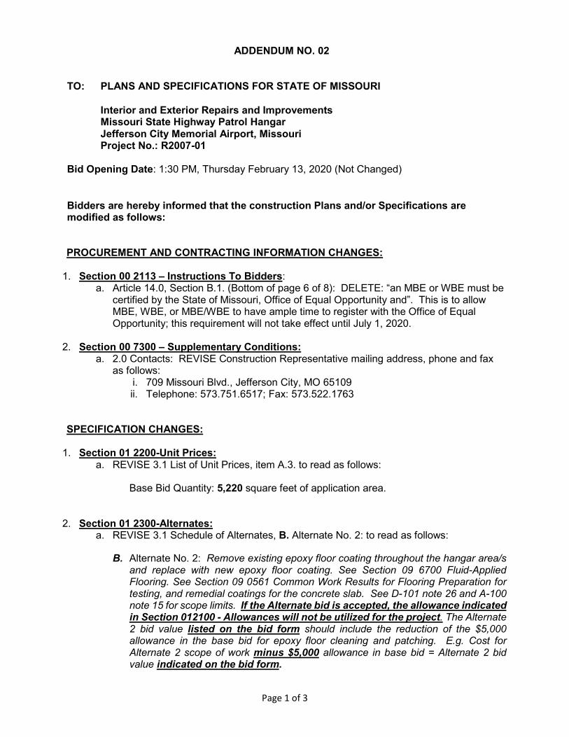
DOOR SCHEDULE
DOOR LEAF SIZE W X H
FRAME SCHEDULE
WO
OD
HO
LL
OW
M
ET
AL
HO
LL
OW
M
ET
AL
FR
AM
E E
LE
V.
FRAME SIZE W X H
F.R
.P
.
DO
OR
E
LE
V.
DETAILS
JA
MB
HE
AD
REMARKS
HA
RD
WA
RE
WO
OD
F.R
.P
.
2'-0" x 7'-0"D
A6 / A601 A6 / A601A
B
C
E
G
EXISTING
* ALL GLAZING
TEMPERED,
TYPICAL
F
EXISTING
--
--
--
C 1 1
1
6
GR
OU
P
5
3'-0" x 7'-0"
GL
AZ
IN
G
3'-4" x 7'-2"
PAIR 3'-0" x 7'-0"B
PAIR 3'-0" x 7'-0"B
6'-4" x 7'-2"
6'-4" x 7'-2"
1
1 A6 / A601 A6 / A601 2
3A9 / A601 A9 / A601
E6 / A601 E9 / A601
-- --
-- --
A9 / A601 A9 / A601A
1
42'-4" x 7'-2"
3'-0" x 7'-0"
A3'-4" x 7'-4" 2
2'-8" x 6'-8"
A3'-0" x 7'-0" 1
DOOR SCHEDULE REMARKS
PRE-HUNG WOOD DOOR1
H A6 / A601 A6 / A601C 1 73'-0" x 7'-0" 3'-4" x 7'-2"
WINDOW SCHEDULE
WINDOW
NUMBER
WINDOW SIZE WxH
± FIELD VERIFY ALL
DIMENSIONS
REMARKS
A
B
EXISTING TO REMAIN
4'-0" x 4'-0"
--
REPLACE EXISTING
DETAIL
A12 / A-601
SE
E D
OO
R S
CH
ED
ULE
DOOR
A
SEE SCHED.
SE
E D
OO
R S
CH
ED
ULE
DOOR
B
6"
SEE SCHED.
8"
2'-0"
SEE DOOR
SCHEDULE
7'-2"
2"
2"2"
FFE
DOOR
C
SE
E D
OO
R S
CH
ED
ULE
SEE SCHED.
5" 5"
5"
2'-9" ±
3'-10"
FRAME
1
SEE DOOR
SCHEDULE
7'-4"
4"
2"2"
FRAME
2
NORTH
MAT'L
BASE
MAT'L
FLOOR
01
SOUTH
WALL
EAST WEST
ROOM FINISH SCHEDULE
REMARKS
NUMBER
ROOM
ROOM NAME MAT'L
CEILING
HEIGHT
CEILING
STORAGE
LOBBY
02
CORRIDOR
RESTROOM
STORAGE
WAITING
03
04
05
06
OFFICE
OFFICE
07
08
09
10
11
12
13OFFICE
14
STAIR
RESTROOM
OFFICE
OFFICE
OFFICE
OFFICE
OFFICE
15
16
OFFICE
HALL
17
18
POLISHED CONC. WB-2 / LPT
FINISHES
STAINED CONCRETE: TBD
CT-1 CARPET TILE
COLOR: TBD
INSTALL: TBD
WLP-1 WALL LINER PANEL
PRODUCT: TBD
SIZE: 16" WIDTH
COLOR: MFG. STANDARD
WP-1 WALL PANEL
PRODUCT: CEMENTIOUS SIDING
SIZE: 48" WIDTH
COLOR: TBD MFG. STANDARD
WB-1 WALL BASE
PRODUCT: RUBBER COVE BASE
SIZE: 4" TALL
COLOR: TBD MFG. STANDARD
WB-2 WALL BASE
PRODUCT: CEMENT BOARD TRIM
SIZE: 4" TALL
COLOR: TBD MFG. STANDARD
LPT LINER PANEL TRIM
P-1 PAINT
PRODUCT: LATEX PAINT
COLOR: TBD
WOOD / P-1 --
EXIST. EXIST. EXIST. A.C.T.
EXIST. EXIST. EXIST. A.C.T.
--
--
--
--
--
--
--EXIST. ACTWB-1
WB-1
WB-1
WB-1
WB-1
WB-1
WB-1
WB-1
WB-1
WB-1
CT-1
CT-1
CT-1
CT-1
CT-1
CT-1
CT-1
CT-1
CT-1
CT-1
EXIST. EXIST. EXIST. EXIST.
EXIST. EXIST. EXIST. EXIST.
EXIST. EXIST. EXIST. EXIST.
P-1 P-1 P-1 P-1
P-1 P-1 P-1 P-1
P-1 P-1 P-1 P-1
P-1 P-1 P-1 P-1
P-1 P-1 P-1 P-1
P-1 P-1 P-1 P-1
P-1 P-1 P-1 P-1
--
--
--
--
--
--
--
--
--
--
WLP-1 WP-1 / P-1
EXIST. EXIST. EXIST. EXIST.
EXIST. EXIST. EXIST. EXIST.
EXIST. A.C.T.
EXIST. A.C.T.
EXIST. ACT
EXIST. A.C.T.
EXIST. A.C.T.
EXIST. ACT
EXIST. A.C.T.
EXIST. A.C.T.
EXIST. ACT
POLISHED CONC.
POLISHED CONC.
POLISHED CONC.
POLISHED CONC.
POLISHED CONC.
WOOD / P-1
WOOD / P-1
WOOD / P-1
WOOD / P-1
WOOD / P-1
-
WB-2 / LPT
WB-1
-
WB-2 / LPT
WLP-1WLP-1
WLP-1
P-1 P-1 P-1 P-1
- - -
WP-1 / P-1 WP-1 / P-1 WP-1 / P-1 WP-1 / P-1
WLP-1 - - -
WLP-1 WLP-1WP-1 / P-1 WP-1 / P-1
7'-4" A
.F
.F
.
8" CMU BOND BEAM -
SEE STRUCTURAL.
TOOLED SEALANT
FRAME ANCHOR
FRP FRAME
GROUT SOLID
7 3/4"
4"
5/8"
7 5/8"
8" CMU - SEE
STRUCTURAL FOR
REINFORCING AND
GROUTING
REQUIREMENTS
1/4" TOOLED SEALANT
EA. SIDE AND BOTTOM
FRP FRAME
7 3/4"
7 5/8"
FRAME ANCHOR
2"
5/8"
7-7/8"
2"
CONTINUOUS BEAD OF
SEALANT - BOTH SIDES (TYP.)
FIBEERGLASS DOOR
FRAME - SEE SCHEDULE
DOOR; SEE
SCHEDULE
FRAME ANCHOR -
MIN. 3 PER JAMB
H.M. FRAME - SEE
DOOR SCHEDULE
DOUBLE METAL STUD
CONTINUOUS BEAD OF
SEALANT (BOTH SIDES; TYP.)
2"
HEAD
JAMB
SILL
THRESHOLD SET IN
FULL BED OF SEALANT
F.R.P. FRAME BEYOND
SEE DOOR SCHEDULE FOR
DOOR TYPE AND SIZE
SEE DOOR SCHEDULE FOR
DOOR TYPE AND SIZE
HEADER; SEE DETAIL
A-601
E12
SIDING TRIM
PRE-FINISHED METAL
LINER PANELS
7 3/4"
LINER PANEL TRIM
CEMENTIOUS SIDING
WALL PANELS
7-3/4"
SIDING TRIM
CEMENTIOUS SIDING
WALL PANELS
6 5/8"
2"
FIBEERGLASS DOOR
FRAME - SEE SCHEDULE
DOOR; SEE
SCHEDULE
FRAME ANCHOR -
MIN. 3 PER JAMB
H.M. FRAME - SEE
DOOR SCHEDULE
DOUBLE METAL STUD
CONTINUOUS BEAD OF
SEALANT (BOTH SIDES; TYP.)
2"
HEAD
JAMB
SILL
F.R.P. FRAME BEYOND
SEE DOOR SCHEDULE FOR
DOOR TYPE AND SIZE
SEE DOOR SCHEDULE FOR
DOOR TYPE AND SIZE
HEADER; SEE DETAIL
A-601
E12
SIDING TRIM
7 3/4"
CEMENTIOUS SIDING
WALL PANELS
7-3/4"
SIDING TRIM
CEMENTIOUS SIDING
WALL PANELS
7-7/8"
2"
CONTINUOUS BEAD OF
SEALANT - BOTH SIDES (TYP.)
ALUMINUM STOREFRONT -
SEE SCHEDULE
DOUBLE METAL STUD
CONTINUOUS BEAD OF
SEALANT (BOTH SIDES; TYP.)
2"
HEAD
JAMB
HEADER; SEE DETAIL
A-601
E12
SIDING TRIM
PRE-FINISHED METAL
WALL PANELS
4 1/2"
METAL PANEL TRIM
CEMENTIOUS SIDING
WALL PANELS
7 7/8"
SIDING TRIM
CEMENTIOUS SIDING
WALL PANELS
4 1/2"
ALUMINUM STOREFRONT -
SEE SCHEDULE
7-7/8"
2"
CONTINUOUS BEAD OF
SEALANT - BOTH SIDES (TYP.)
ALUMINUM STOREFRONT -
SEE SCHEDULE
CONTINUOUS BEAD OF
SEALANT (BOTH SIDES; TYP.)
2"
HEAD
JAMB
HEADER EXISTING
A-601
E12
GYPSUM BOARD
PRE-FINISHED METAL
WALL PANELS
4 1/2"
METAL PANEL TRIM
7 7/8"
GYPSUM BOARD
4 1/2"
ALUMINUM STOREFRONT -
SEE SCHEDULE
ISSUE DATE:
SHEET NUMBER:
SITE #
CHECKED BY:DRAWN BY:
DESIGNED BY:
DATE:REVISION:
FACILITY #
PROJECT #
SHEET TITLE:
REVISION:DATE:
REVISION:DATE:
CAD DWG FILE:
STATE OF MISSOURIMICHAEL L. PARSON,
GOVERNOR
OFFICE OF ADMINISTRATIONDIVISION OF FACILITIESMANAGEMENT,DESIGN AND CONSTRUCTION
DEPARTMENT OF
PUBLIC SAFETY
Interior and Exterior
MSHP AIRCRAFT HANGARRepairs and Improvements
CITY OF JEFFERSON AIRPORT
JEFFERSON CITY, MISSOURI
R2007-016011
8136011011
12/27/2019
A301LCEMEM
FINISH, DOOR &WINDOW SCHEDULES& DETAILS
A-60118 OF 28 SHEETS12/27/2019
PWArchitects, Inc.
Ph:(573) 449-2683 Fax:(573) 442-6213
Columbia, Missouri 65203
2120 Forum Blvd, Suite 101
PWA Project No. 201919
1 2 3 4 5 6 7 8 9 10 11 12 13 14 15
A
B
C
D
E
F
G
H
J
K
L
M
DOOR AND FRAME ELEVATIONS
SCALE: 1/4" = 1'-0"
H6
DOOR FRAME DETAIL
SCALE: 3" = 1'-0"
E6
DOOR FRAME DETAIL
SCALE: 3" = 1'-0"
E9
DOOR FRAME DETAIL
SCALE: 1-1/2" = 1'-0"
A6
DOOR FRAME DETAIL
SCALE: 1-1/2" = 1'-0"
A9
WINDOW DETAIL - BASE BID
SCALE: 1-1/2" = 1'-0"
A12
WINDOW DETAIL - ALTERNATE
SCALE: 1-1/2" = 1'-0"
E12
1 ADDENDUM 2
02/06/2020
1
1
1
1
1