Embed Size (px)
Citation preview

ADDENDUM #4
TOWN OF SMITHFIELD SEWER AUTHORITY SODIUM HYPOCHLORITE (NaHCl) STORAGE TANK
REPLACMENT AT THE SMITHFIELD WWTF April 4, 2018
Addendum #4 shall only be applicable to bidders attending the mandatory pre-bid conference on April 4, 2018 at the Smithfield Wastewater Treatment Facility. This Addendum shall modify the advertised request for proposals (RFP) as follows: TIMELINE:
Request for Proposals Issued March 8, 2018
Mandatory Pre-Proposal Meeting April 4, 2018 at 10:00 am
Deadline for questions from vendors April 6, 2018 at 4:00 pm
Proposal Due Date and Opening April 13, 2018 at 10:00 am
Contract Start Date June 1, 2018
Contract End Date September 28, 2018 LEVEL SENSOR SPECIFICATIONS See pages below.

TI396F/24/ae/05.07
Technical Information
Prosonic S
FDU91/91F/92/93/95/96
Ultrasonic sensors for non-contact continuous
level and flow measurement;
for connection to the transmitter FMU90
FDU92
FDU93
FDU95
FDU96
FDU91
FDU91F
Application
• Continuous, non-contact level measurement of fluids,
pastes, sludges and powdery to coarse bulk materials
• Flow measurement in open channels and measuring
weirs
• Maximum measuring range
– FDU91/FDU91F:
33 ft (10 m) in fluids
16 ft (5 m) in bulk materials
– FDU92:
65 ft (20 m) in fluids
33 ft (10 m) in bulk materials
– FDU93:
85 ft (25 m) in fluids
50 ft (15 m) in bulk materials
– FDU95:
148 ft (45 m) in bulk materials
– FDU96:
230 ft (70 m) in bulk materials
• Suited for explosion hazardous areas
Your benefits
• Non-contact measurement method; minimizes service
requirements
• Integrated temperature sensor for time-of-flight
correction. Accurate measurements are possible, even
if temperature changes are present
• Hermetically welded PVDF sensors FDU91/92 for
fluid measurement; for highest chemical resistance
• Integrated automatical sensor detection for
transmitters FMU90; simple commissioning
• Can be installed up to 1000 ft (300 m) from the
transmitter
• Suited for rough ambient conditions thanks to separate
installation from the transmitter
• Reduced build-up formation because of the self-
cleaning effect
• Integrated heating against a build-up of ice at the
sensor (optional); ensures reliable measurement
• Weather resistant and flood-proof (NEMA 6P/IP68)
• Dust-Ex and Gas-Ex certificats available (ATEX, FM,
CSA)
Prosonic S FDU91/91F/92/93/95/96
2 Endress+Hauser
Table of Contents
Function and system design. . . . . . . . . . . . . . . . . . . . . 3
Measuring principle . . . . . . . . . . . . . . . . . . . . . . . . . . . . . . . . . . . 3
Time-of-flight correction . . . . . . . . . . . . . . . . . . . . . . . . . . . . . . . . 3
Blocking distance . . . . . . . . . . . . . . . . . . . . . . . . . . . . . . . . . . . . . 3
Transmitter . . . . . . . . . . . . . . . . . . . . . . . . . . . . . . . . . . . . . . . . . 3
Input . . . . . . . . . . . . . . . . . . . . . . . . . . . . . . . . . . . . . . 4
Measuring range . . . . . . . . . . . . . . . . . . . . . . . . . . . . . . . . . . . . . . 4
Operating frequency . . . . . . . . . . . . . . . . . . . . . . . . . . . . . . . . . . . 5
Output . . . . . . . . . . . . . . . . . . . . . . . . . . . . . . . . . . . . . 5
Signal transmission . . . . . . . . . . . . . . . . . . . . . . . . . . . . . . . . . . . . 5
Auxiliary energy . . . . . . . . . . . . . . . . . . . . . . . . . . . . . 5
Power supply . . . . . . . . . . . . . . . . . . . . . . . . . . . . . . . . . . . . . . . . 5
Sensor heater (for FDU91) . . . . . . . . . . . . . . . . . . . . . . . . . . . . . . 5
Electrical connection . . . . . . . . . . . . . . . . . . . . . . . . . . 6
Connection diagram . . . . . . . . . . . . . . . . . . . . . . . . . . . . . . . . . . . 6
Connection hints . . . . . . . . . . . . . . . . . . . . . . . . . . . . . . . . . . . . . 7
Connection of the sensor heater (for FDU91F) . . . . . . . . . . . . . . . 7
Extenxion cables for the sensors . . . . . . . . . . . . . . . . . . . . . . . . . . 7
Shortening the sensor cable . . . . . . . . . . . . . . . . . . . . . . . . . . . . . 8
Installation conditions . . . . . . . . . . . . . . . . . . . . . . . . . 9
Installation options (Examples) . . . . . . . . . . . . . . . . . . . . . . . . . . . 9
Installation conditions for level measurements . . . . . . . . . . . . . . 10
Installation conditions for flow measurements . . . . . . . . . . . . . . . 11
Flush mounting with slip-on flange FAU80 . . . . . . . . . . . . . . . . . 12
Nozzle installation . . . . . . . . . . . . . . . . . . . . . . . . . . . . . . . . . . . 13
Ultrasound guide pipe . . . . . . . . . . . . . . . . . . . . . . . . . . . . . . . . . 13
Ambient conditions . . . . . . . . . . . . . . . . . . . . . . . . . . 13
Ingress protection . . . . . . . . . . . . . . . . . . . . . . . . . . . . . . . . . . . . 13
Vibration resistance . . . . . . . . . . . . . . . . . . . . . . . . . . . . . . . . . . 13
Storage temperature . . . . . . . . . . . . . . . . . . . . . . . . . . . . . . . . . . 13
Thermal shock resistance . . . . . . . . . . . . . . . . . . . . . . . . . . . . . . 13
Electromagnetic compatibility . . . . . . . . . . . . . . . . . . . . . . . . . . . 13
Process conditions . . . . . . . . . . . . . . . . . . . . . . . . . . . 14
Process temperature / Process pressure . . . . . . . . . . . . . . . . . . . 14
Mechanical construction . . . . . . . . . . . . . . . . . . . . . . 14
Dimensions FDU91 . . . . . . . . . . . . . . . . . . . . . . . . . . . . . . . . . . 14
Dimensions FDU91F . . . . . . . . . . . . . . . . . . . . . . . . . . . . . . . . . 14
Dimensions FDU92 . . . . . . . . . . . . . . . . . . . . . . . . . . . . . . . . . . 15
Dimensions FDU93 . . . . . . . . . . . . . . . . . . . . . . . . . . . . . . . . . . 15
Dimensions FDU95 . . . . . . . . . . . . . . . . . . . . . . . . . . . . . . . . . . 15
Dimensions FDU96 . . . . . . . . . . . . . . . . . . . . . . . . . . . . . . . . . . 16
Weight . . . . . . . . . . . . . . . . . . . . . . . . . . . . . . . . . . . . . . . . . . . . 16
Materials . . . . . . . . . . . . . . . . . . . . . . . . . . . . . . . . . . . . . . . . . . 16
Connecting cable . . . . . . . . . . . . . . . . . . . . . . . . . . . . . . . . . . . . 16
Certificates and Approvals . . . . . . . . . . . . . . . . . . . . . 17
CE mark . . . . . . . . . . . . . . . . . . . . . . . . . . . . . . . . . . . . . . . . . . 17
Ex approval . . . . . . . . . . . . . . . . . . . . . . . . . . . . . . . . . . . . . . . . 17
External standards and guidelines . . . . . . . . . . . . . . . . . . . . . . . . 17
Ordering information. . . . . . . . . . . . . . . . . . . . . . . . . 17
Product structure FDU91 . . . . . . . . . . . . . . . . . . . . . . . . . . . . . . 17
Product structure FDU91F . . . . . . . . . . . . . . . . . . . . . . . . . . . . . 18
Product structure FDU92 . . . . . . . . . . . . . . . . . . . . . . . . . . . . . . 18
Product structure FDU93 . . . . . . . . . . . . . . . . . . . . . . . . . . . . . . 19
Product structure FDU95 . . . . . . . . . . . . . . . . . . . . . . . . . . . . . . 19
Product structure FDU96 . . . . . . . . . . . . . . . . . . . . . . . . . . . . . . 20
Scope of delivery . . . . . . . . . . . . . . . . . . . . . . . . . . . . . . . . . . . . 20
Accessories . . . . . . . . . . . . . . . . . . . . . . . . . . . . . . . . 20
Extension cable for sensors . . . . . . . . . . . . . . . . . . . . . . . . . . . . . 20
Protective cover for FDU91 . . . . . . . . . . . . . . . . . . . . . . . . . . . . 21
Flanges . . . . . . . . . . . . . . . . . . . . . . . . . . . . . . . . . . . . . . . . . . . 21
Cantilever . . . . . . . . . . . . . . . . . . . . . . . . . . . . . . . . . . . . . . . . . 21
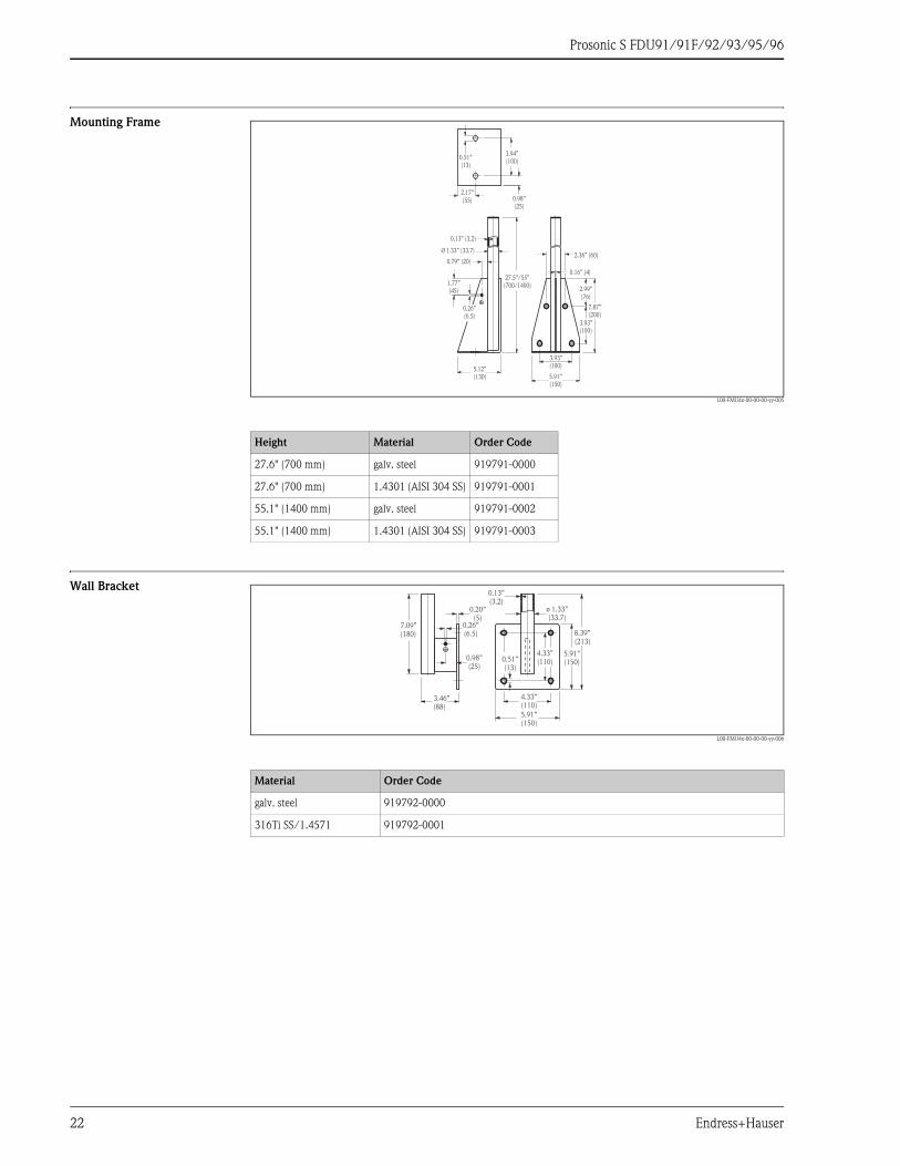
Mounting Frame . . . . . . . . . . . . . . . . . . . . . . . . . . . . . . . . . . . . 22
Wall Bracket . . . . . . . . . . . . . . . . . . . . . . . . . . . . . . . . . . . . . . . 22
Alignment unit FAU40 . . . . . . . . . . . . . . . . . . . . . . . . . . . . . . . 23
Supplementary documentation . . . . . . . . . . . . . . . . . 23
Innovation booklet . . . . . . . . . . . . . . . . . . . . . . . . . . . . . . . . . . . 23
Technical Information . . . . . . . . . . . . . . . . . . . . . . . . . . . . . . . . 23
Operating instructions (for transmitter FMU90) . . . . . . . . . . . . . 23
Description of Instrument Functions (for transmitter FMU90) . . . 24
Safety Instructions . . . . . . . . . . . . . . . . . . . . . . . . . . . . . . . . . . . 24

Prosonic S FDU91/91F/92/93/95/96
Endress+Hauser 3
Function and system design
Measuring principle
L00-FMU90xxx-15-00-08-xx-009
BD: blocking distance; D: distance from sensor membrane to fluid surface; E: empty distance F: span (full distance);L: level; V: volume (or mass); Q: flow
The sensor transmits ultrasonic pulses in the direction of the product surface. There, they are reflected back
and received by the sensor. The transmitter Prosonic S measures the time t between pulse transmission and
reception. From t (and the velocity of sound c) it calculates the distance D from the sensor membrane to the
product surface:
D = c · t/2
From D results the desired measuring value:
• level L
• volume V
• flow Q across measuring weirs or open channels
Time-of-flight correction In order to compensate for temperature dependent time-of-flight changes, a temperature sensor is integrated
in the ultrasonic sensors.
Blocking distance The level L may not extend into the blocking distance BD. Level echoes within the blocking distance can not
be evaluated due to the transient characteristics of the sensor and thus a reliable measurement is not possible.
The blocking distance BD is dependent on the type of sensor:
Transmitter The sensors can be connected to the transmitter FMU90. The transmitter recognizes the type of sensor
automatically.
FDU9x
Prosonic SFMU90
Prosonic SFMU90
FDU9x
D
Q
100%
0%
D
L
FE
BD
V
Type of sensor Blocking distance (BD)
FDU91/FDU91F 1 ft (0.3 m)
FDU92 1.3 ft (0.4 m)
FDU93 2 ft (0.6 m)
FDU95 - *1*** (low temperature version) 2.3 ft (0.7 m)
FDU95 - *2*** (high temperature version) 3 ft (0.9 m)
FDU96 5 ft (1.6 m)
Prosonic S FDU91/91F/92/93/95/96
4 Endress+Hauser
Input
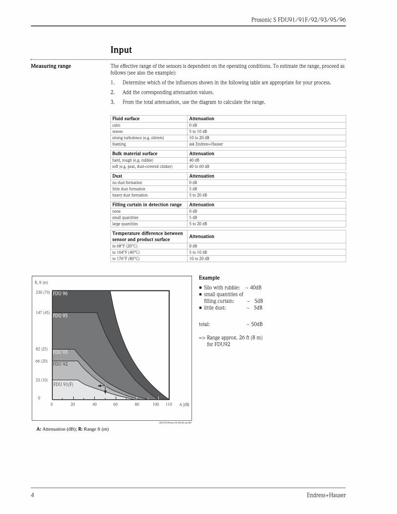
Measuring range The effective range of the sensors is dependent on the operating conditions. To estimate the range, proceed as
follows (see also the example):
1. Determine which of the influences shown in the following table are appropriate for your process.
2. Add the corresponding attenuation values.
3. From the total attenuation, use the diagram to calculate the range.
Fluid surface Attenuation
calm 0 dB
waves 5 to 10 dB
strong turbulence (e.g. stirrers) 10 to 20 dB
foaming ask Endress+Hauser
Bulk material surface Attenuation
hard, rough (e.g. rubble) 40 dB
soft (e.g. peat, dust-covered clinker) 40 to 60 dB
Dust Attenuation
no dust formation 0 dB
little dust formation 5 dB
heavy dust formation 5 to 20 dB
Filling curtain in detection range Attenuation
none 0 dB
small quantities 5 dB
large quantities 5 to 20 dB
Temperature difference between
sensor and product surfaceAttenuation
to 68°F (20°C) 0 dB
to 104°F (40°C) 5 to 10 dB
to 176°F (80°C) 10 to 20 dB
L00-FDU9xxxx-05-00-00-xx-001
A: Attenuation (dB); R: Range ft (m)
Example
• Silo with rubble: ~ 40dB
• small quantities of
filling curtain: ~ 5dB
• little dust: ~ 5dB
total: ~ 50dB
=> Range approx. 26 ft (8 m)
for FDU92
0 20 40 60 80 100 110
147 (45)
230 (70)
82 (25)
66 (20)
33 (10)
0
FDU 95FDU 95
FDU 96FDU 96
FDU 93FDU 93
FDU 92
FDU 91(F)
A [dB]
R, ft (m)

Prosonic S FDU91/91F/92/93/95/96
Endress+Hauser 5
Operating frequency
Output
Signal transmission Analog voltages
Auxiliary energy
Power supply Supplied by the transmitter FMU90
Sensor heater (for FDU91) The FDU91 sensor is available in a version with heater. The power for this heater must be provided by an
external power supply unit. The supply voltage is connected to the brown (BN) and blue (BU) wires of the
sensor cable.
Technical data
• 24 VDC ±10%; residual ripple < 100 mV
• 250 mA per sensor
! NOTE!
For the FDU91 with sensor heater, the integrated temperature sensor can not be used. Instead, an external
temperature sensor (Pt100 or FMT131 from Endress+Hauser) must be used. The transmitter FMU90 is
available in a version with an input for the external temperature sensor. For details refer to Technical
Information TI397F.
Sensor Operating frequency
FDU91 43 kHz
FDU91F 42 kHz
FDU92 30 kHz
FDU93 27 kHz
FDU95 - *1***
(low temperature version)17 kHz
FDU95 - *2***
(high temperature version)18 kHz
FDU96 11 kHz

Prosonic S FDU91/91F/92/93/95/96
6 Endress+Hauser
Electrical connection
Connection diagram
L00-FDU9xxxx-04-00-00-xx-002
(A): without sensor heater;(B): with sensor heater;(C): grounding at the terminal box;(D): grounding at the transmitter FMU90;(1): Shield of the sensor cable;(2): Terminal box;(3): Shield of the extension cable;Wire colors: YE = yellow; BK = black; RD = red; BU = blue; BN = brown; GNYE = green-yellow
YE9
(12)
BK10
(13)
RD11
(14)
FDU91/92(FDU80/80F/81/81F/82)
BKYE RD
(1)
YE9
(12)
BK10
(13)
RD11
(14)
FDU91F/93/95/96(FDU83/84/85/86)
BKYE RD GNYE
(2)
(3)
FMU90
(1)
(2)
(3)
FMU90
YE9
(12)
BK10
(13)
RD11
(14)
FDU91(FDU80/81)
BKYE RD
(1)
(2)
(3)
FMU90
BN BU
24 VDC
+ -
(A) (B)
(C)
max.985 ft
(300 m)
YE9
(12)
BK10
(13)
RD11
(14)
FDU91F/93/95/96(FDU83/84/85/86)
BKYE RD GNYE
(1)
FMU90
(D)
max.100 ft(30 m)
FDU91/92
(FDU80/80F/81/81F/82)
FDU91F/93/95/96(FDU83/84/85/86)
max.985 ft
(300 m)
max.100 ft(30 m)

Prosonic S FDU91/91F/92/93/95/96
Endress+Hauser 7
Connection hints
" Caution!
In order to avoid interference signals, the sensor cables should not be laid parallel to high voltage electric power
lines. The cables may not be laid in the proximity to frequency converters.
" Caution!
The cable shield serves as a return cable and must be connected to the transmitter without any electrical break.
With the pre-assembled cables, the shield ends in a black strand (BK). With the extension cable, the shield must
be twisted together and connected to the "BK" terminal.
# Warning!
The sensors FDU83, FDU84, FDU85 and FDU86 with an ATEX, FM or CSA certificate are not certified for
connection to the FMU90 transmitter.
# Warning!
For the sensors FDU91F/93/95/96 and FDU83/84/85/86:
The ground lead (GNYE) must be connected to the local potential equalization after a maximum distance
of 100 ft (30 m). This can be done:
• either at the terminal box
• or at the transmitter FMU90 or in the cabinet (if the distance to the sensor does not exceed 100 ft / 30 m).
! Note!
For easier mounting, it is advisable to use the sensors FDU91/92 and FDU80/80F/81/81F/82 with a
maximum cable length of 100 ft (30 m) as well. For longer distances an extension cable with a terminal box
should be used.
Connection of the sensor
heater (for FDU91F)
The FDU91 sensor is available in a version with heater. The power for this heater must be provided by an
external power supply unit. The supply voltage is connected to the brown (BN) and blue (BU) wires of the
sensor cable.
Technical Data
• 24 VDC ± 10%; residual ripple < 100 mV
• 250 mA per sensor
Extenxion cables for the
sensors
For distances up to 100 ft (30 m) the sensor can be directly connected by the sensor cable. For longer distances,
it is recommended to use an extension cable. The extension cable is connected via a terminal box. The total
length (sensor cable + extension cable) may be up to 1000 ft (300 m).
" Caution!
If the terminal box is installed in explosion hazardous areas, all applicable national guidelines must be observed.
Suitable extension cables can be obtained from Endress+Hauser (s. chapter "Accessories")
Alternatively, cables with the following properties can be used:
• Number of cores according to the connection diagram (see above)
• Braided wire shield for the yellow (YE) and red (RD) core (no foil shield)
• Length: up to 1000 ft (300 m), sensor cable + extension cable
• Cross section: 16 to 18 AWG (0.75 mm2 to 2.5 mm2)
• Up to 6 Ω per core
• Max. 60 nF
• For FDU91F/93/95/96 and FDU 83/84/85/86:
The ground lead must not be within the shielding.

Prosonic S FDU91/91F/92/93/95/96
8 Endress+Hauser
Shortening the sensor cable If required, the sensor cable can be shortened. Please note:
• Do not damage the wires when removing the insulation.
• The cable is shielded by a metallic braiding. This shielding serves as a return cable and corresponds to the
black (BK) strand of the unshortened cable. After shortening the cable, loosen the metallic braiding, twist it
together securely and connect it to the "BK" terminal.
" Caution!
The protective ground conductor (GNYE), which is present in some of the sensor cables, may not be electrically
connected to the cable shield.
L00-FMU90xxx-04-00-00-xx-015
Colors of the strands: YE = yellow; BK = black; RD = red; BU = blue; BN = brown; GNYE = green-yellow
! Note!
The blue (BU) and brown (BN) wires are only present for sensors with heater.
FDU91/92(FDU80/80F/81/81F/82)
FDU91F/93/95/96(FDU83/84/85/86)
RD
BK
YE
RD
BK
YE
24
VD
CBN (+)
BU (-)
GNYE
1. 1.
BN
BU RD
YE
GNYE
RD
YE

Prosonic S FDU91/91F/92/93/95/96
Endress+Hauser 9
Installation conditions
Installation options
(Examples)
L00-FDU9xxxx-17-00-00-xx-001
A: at girder or angle bracket; B: with alignment unit FAU40; in ATEX Zone 20 the alignment unit can be used for zone separation; C: with a 1" sleeve welded to a grating
L00-FDU9xxxx-17-00-00-xx-007
A: Installation with cantilever and wall bracket; B: Installation with cantilever and mounting frame; C: The cantilever can be turned in order to position the sensor over the center of the flume.Cantilever, wall bracket and mounting frame are available as accessories (see chapter "Accessories").
" Caution!
The cable of the sensors is not designed as a supporting cable. Do not use it as a suspension wire.
" Caution!
The sensor membrane is part of the measuring system and must not be damaged during installation.
A B C
Zone 20-
Zone 21-. FAU40
A BC
FDU9x FDU9x

Prosonic S FDU91/91F/92/93/95/96
10 Endress+Hauser
Installation conditions for
level measurements
L00-FDU9xxxx-17-00-00-xx-003
• If possible, install the sensor so that its lower edge projects into the vessel.
• Make sure that the maximum level does not reach into the blocking distance (BD, see table).
• Do not install the sensor in the middle of the tank (2). We recommend leaving a distance (1) between the
sensor and the tank wall measuring 1/6 of the tank diameter.
• Avoid measurements through the filling curtain (3).
• Make sure that equipment (4) such as limit switches, temperature sensors, baffles etc. are not located within
the emitting angle α. Emitting angles of the individual sensors are given in the table below. In particular,
symmetrical equipment (5) such as heating coils etc. can influence the measurement.
• Align the sensor vertically to the product surface (6). An alignment unit (FAU40) is available as an accessory
(see chapter "Accessories").
• If the two-channel version of the transmitter FMU90 is used, both sensors can be mounted in one vessel.
• To estimate the detection range, use the 3 dB emitting angle α:
# Warning!
All national guidelines applicable must be observed in explosion hazardous areas.
1/6D
D
r
�R
BD
1
2 3
4
5
6
BD
BD
Sensor Blocking distance BD α (typically) Application L (max) r (max)
FDU91 1 ft (0.3 m) 9°fluids 33 ft (10 m) 2.6 ft (0.79 m)
bulk materials 16 ft (5 m) 1.3 ft (0.39 m)
FDU91F 1 ft (0.3 m) 12°fluids 33 ft (10 m) 3.4 ft (1.05 m)
bulk materials 16 ft (5 m) 1.7 ft (0.53 m)
FDU92 1.3 ft (0.4 m) 11°fluids 65 ft (20 m) 6.3 ft (1.92 m)
bulk materials 33 ft (10 m) 3 ft (0.96 m)
FDU93 2 ft (0.6 m) 4°fluids 82 ft (25 m) 2.8 ft (0.87 m)
bulk materials 50 ft (15 m) 1.7 ft (0.52 m)
FDU95 • 2 ft / 0.7 m (low temperature version)
• 3 ft / 0.9 m (high temperature version)
5° bulk materials 147 ft (45 m) 6.4 ft (1.96 m)
FDU96 5 ft (1.6 m) 6° bulk materials 230 ft (70 m) 12 ft (3.6 m)

Prosonic S FDU91/91F/92/93/95/96
Endress+Hauser 11
Installation conditions for flow
measurements
• Install the sensor at the inflow side (A), above the maximum water level Hmax plus the blocking distance BD.
• Position the sensor in the middle of the channel or weir.
• Align the sensor vertically to the water surface.
• Comply to the installation distance of the channel or weir.1)
• Use a protective cover, in order to protect the sensor from direct sun or rain. A protective cover is available
for the sensor FDU91 (see chapter "Accessories").
Example: Khafagi-Venturi flume
L00-FDU9xxxx-17-00-00-xx-004
(A): inflow side; (B): outflow side
Example: V-notch weir
L00-FDU9xxxx-17-00-00-xx-005
1) The installation distances of important flumes and weirs are specified in the Operating Instructions BA 289F (FMU90 with HART) and BA 293F (FMU90 with
PROFIBUS).
1 x b0
b0
BD
FDU 91
H max
(A) (B)
max
min.3 H
BD
FDU 91
Hmax
Prosonic S FDU91/91F/92/93/95/96
12 Endress+Hauser
Flush mounting with
slip-on flange FAU80
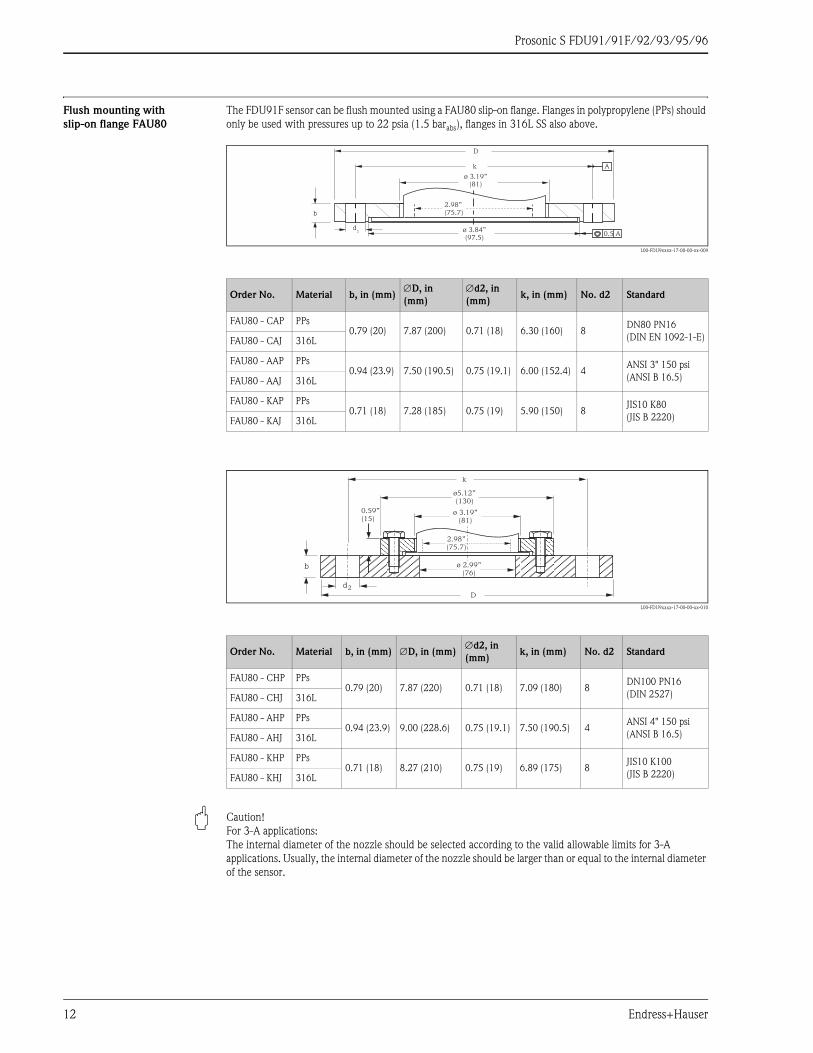
The FDU91F sensor can be flush mounted using a FAU80 slip-on flange. Flanges in polypropylene (PPs) should
only be used with pressures up to 22 psia (1.5 barabs), flanges in 316L SS also above.
L00-FDU9xxxx-17-00-00-xx-009
L00-FDU9xxxx-17-00-00-xx-010
" Caution!
For 3-A applications:
The internal diameter of the nozzle should be selected according to the valid allowable limits for 3-A
applications. Usually, the internal diameter of the nozzle should be larger than or equal to the internal diameter
of the sensor.
Order No. Material b, in (mm)∅D, in
(mm)
∅d2, in
(mm)k, in (mm) No. d2 Standard
FAU80 - CAP PPs0.79 (20) 7.87 (200) 0.71 (18) 6.30 (160) 8
DN80 PN16
(DIN EN 1092-1-E)FAU80 - CAJ 316L
FAU80 - AAP PPs0.94 (23.9) 7.50 (190.5) 0.75 (19.1) 6.00 (152.4) 4
ANSI 3" 150 psi
(ANSI B 16.5)FAU80 - AAJ 316L
FAU80 - KAP PPs0.71 (18) 7.28 (185) 0.75 (19) 5.90 (150) 8
JIS10 K80
(JIS B 2220)FAU80 - KAJ 316L
Order No. Material b, in (mm) ∅D, in (mm)∅d2, in
(mm)k, in (mm) No. d2 Standard
FAU80 - CHP PPs0.79 (20) 7.87 (220) 0.71 (18) 7.09 (180) 8
DN100 PN16
(DIN 2527)FAU80 - CHJ 316L
FAU80 - AHP PPs0.94 (23.9) 9.00 (228.6) 0.75 (19.1) 7.50 (190.5) 4
ANSI 4" 150 psi
(ANSI B 16.5)FAU80 - AHJ 316L
FAU80 - KHP PPs0.71 (18) 8.27 (210) 0.75 (19) 6.89 (175) 8
JIS10 K100
(JIS B 2220)FAU80 - KHJ 316L
0.5 A
A
D
k
ø 3.84”(97.5)
d2
b
ø 3.19”(81)
2.98”(75.7)
d2
k
ø 2.99”(76)
D
ø 3.19”(81)
ø5.12”(130)
b
0.59”(15)
2.98”(75.7)
Prosonic S FDU91/91F/92/93/95/96
Endress+Hauser 13
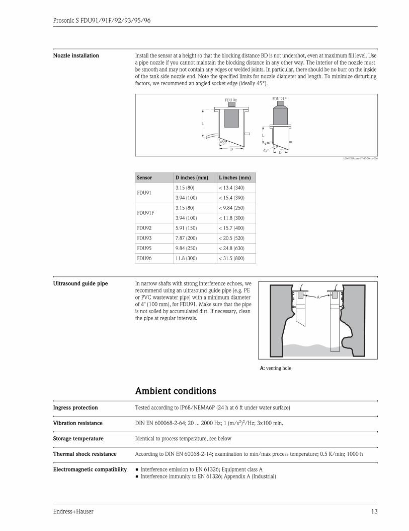
Nozzle installation Install the sensor at a height so that the blocking distance BD is not undershot, even at maximum fill level. Use
a pipe nozzle if you cannot maintain the blocking distance in any other way. The interior of the nozzle must
be smooth and may not contain any edges or welded joints. In particular, there should be no burr on the inside
of the tank side nozzle end. Note the specified limits for nozzle diameter and length. To minimize disturbing
factors, we recommend an angled socket edge (ideally 45°).
L00-FDU9xxxx-17-00-00-xx-006
Ultrasound guide pipe
Ambient conditions
Ingress protection Tested according to IP68/NEMA6P (24 h at 6 ft under water surface)
Vibration resistance DIN EN 600068-2-64; 20 ... 2000 Hz; 1 (m/s2)2/Hz; 3x100 min.
Storage temperature Identical to process temperature, see below
Thermal shock resistance According to DIN EN 60068-2-14; examination to min/max process temperature; 0.5 K/min; 1000 h
Electromagnetic compatibility • Interference emission to EN 61326; Equipment class A
• Interference immunity to EN 61326; Appendix A (Industrial)
Sensor D inches (mm) L inches (mm)
FDU913.15 (80) < 13.4 (340)
3.94 (100) < 15.4 (390)
FDU91F3.15 (80) < 9.84 (250)
3.94 (100) < 11.8 (300)
FDU92 5.91 (150) < 15.7 (400)
FDU93 7.87 (200) < 20.5 (520)
FDU95 9.84 (250) < 24.8 (630)
FDU96 11.8 (300) < 31.5 (800)
L
D
FDU 9x
45°
L
D
FDU 91F
45°
In narrow shafts with strong interference echoes, we
recommend using an ultrasound guide pipe (e.g. PE
or PVC wastewater pipe) with a minimum diameter
of 4" (100 mm), for FDU91. Make sure that the pipe
is not soiled by accumulated dirt. If necessary, clean
the pipe at regular intervals.
A: venting hole
A
Prosonic S FDU91/91F/92/93/95/96
14 Endress+Hauser
Process conditions
Process temperature
Process pressure
Mechanical construction
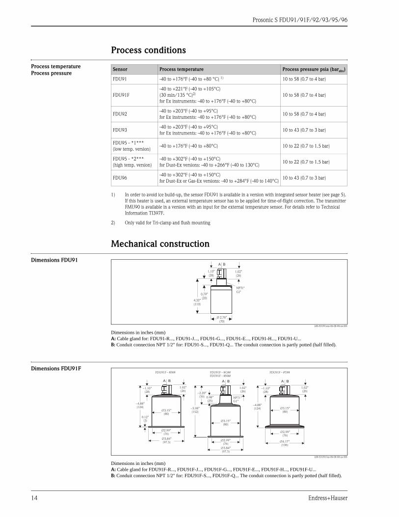
Dimensions FDU91
L00-FDU91xxx-06-00-00-xx-001
Dimensions in inches (mm)A: Cable gland for: FDU91-R..., FDU91-J..., FDU91-G..., FDU91-E..., FDU91-H..., FDU91-U...B: Conduit connection NPT 1/2" for: FDU91-S..., FDU91-Q... The conduit connection is partly potted (half filled).
Dimensions FDU91F
L00-FDU91Fxx-06-00-00-xx-001
Dimensions in inches (mm)A: Cable gland for FDU91F-R..., FDU91F-J..., FDU91F-G..., FDU91F-E..., FDU91F-H..., FDU91F-U...B: Conduit connection NPT 1/2" for: FDU91F-S..., FDU91F-Q... The conduit connection is partly potted (half filled).
Sensor Process temperature Process pressure psia (barabs)
FDU91 -40 to +176°F (-40 to +80 °C) 1)
1) In order to avoid ice build-up, the sensor FDU91 is available in a version with integrated sensor heater (see page 5).
If this heater is used, an external temperature sensor has to be applied for time-of-flight correction. The transmitter
FMU90 is available in a version with an input for the external temperature sensor. For details refer to Technical
Information TI397F.
10 to 58 (0.7 to 4 bar)
FDU91F
-40 to +221°F (-40 to +105°C)
(30 min/135 °C)2)
for Ex instruments: -40 to +176°F (-40 to +80°C)
2) Only valid for Tri-clamp and flush mounting
10 to 58 (0.7 to 4 bar)
FDU92-40 to +203°F (-40 to +95°C)
for Ex instruments: -40 to +176°F (-40 to +80°C)10 to 58 (0.7 to 4 bar)
FDU93-40 to +203°F (-40 to +95°C)
for Ex instruments: -40 to +176°F (-40 to +80°C)10 to 43 (0.7 to 3 bar)
FDU95 - *1***
(low temp. version)-40 to +176°F (-40 to +80°C) 10 to 22 (0.7 to 1.5 bar)
FDU95 - *2***
(high temp. version)
-40 to +302°F (-40 to +150°C)
for Dust-Ex versions: -40 to +266°F (-40 to 130°C)10 to 22 (0.7 to 1.5 bar)
FDU96-40 to +302°F (-40 to +150°C)
for Dust-Ex or Gas-Ex versions: -40 to +284°F (-40 to 140°C)10 to 43 (0.7 to 3 bar)
4.33”(110)
0.79”(20)
Ø 2.76”(70)
NPT1"G1"
A B
1.02”(26)
1.10”(28)
�3.84”(97.5)
�3.84”(97.5)
�2.99”(76)
�2.99”(76)
�2.99”(76)
~4.88”(124)
�3.15”(80)
�3.15”(80)�3.15”
(80)
~1.10”(28)
1.02”(26)
1.02”(26)
1.02”(26)
~1.10”(28)
~5.98”(152)
~2.20”(56)
�4.17”(106)
~4.88”(124)
0.98”(25)
0.12”(3)
NPT1”G1”
FDU91F - #F## FDU91F - #G##FDU91F - #N##
FDU91F - #T##
A B A B A B

Prosonic S FDU91/91F/92/93/95/96
Endress+Hauser 15
Dimensions FDU92
L00-FDU92xxx-06-00-00-xx-001
Dimensions in inches (mm)A: Cable gland for: FDU92-R..., FDU92-J..., FDU92-G..., FDU92-E..., FDU92-H..., FDU92-U...B: Conduit connection NPT 1/2" for: FDU92-S..., FDU92-Q...
The conduit connection is partly potted (half filled).
Dimensions FDU93
L00-FDU93xxx-06-00-00-xx-001
Dimensions in inches (mm)A: Cable gland for: FDU93-R..., FDU93-J..., FDU93-G..., FDU93-E..., FDU93-H..., FDU93-U...B: Conduit connection NPT 1/2" for: FDU93-T..., FDU93-P...
The conduit connection is partly potted (half filled).
Dimensions FDU95
L00-FDU95xxx-06-00-00-xx-001
Dimensions in inches (mm)A: CAble gland for: FDU95-R..., FDU95-J..., FDU95-E..., FDU95-H..., FDU95-U...B: Conduit connection NPT 1/2" for: FDU95-P..., FDU95-T...
The conduit connection is partly potted (half filled).
4.92”(125)
0.79”(20)
Ø3.86”(98)
NPT1"G1"
A B
1.02”(26)
1.10”(28)
5.71”(145)
Ø7.36”(187)
0.98”(25)
1.10”(28)
1.02”(26)
NPT1"G1"
A B
6.06”(154)
Ø9.25”(235)
0.98”(25)
NPT1"G1”
1.02”(26)
1.10”(28)
A B

Prosonic S FDU91/91F/92/93/95/96
16 Endress+Hauser
Dimensions FDU96
L00-FDU96xxx-06-00-00-xx-001
Dimensions in inches (mm)A: Cable gland for: FDU95-R..., FDU95-J..., FDU95-E..., FDU95-H..., FDU95-U...B: Conduit connection NPT 1/2" for: FDU95-P..., FDU95-T... The conduit connection is partly potted (half filled).
Weight
Materials
Connecting cable 16 to 1000 ft (5 to 300 m)
For cable length > 100 ft (30 m), an extension cable is recommended.
In this case, the total length (sensor cable + extension cable) must not exceed 1000 ft (300 m).
17.7”(450)
0.98”(25)
Ø7.80”(198)
9.06”(230)
NPT1"G1"
1.02”(26)
1.10”(28)
A B
Sensor Weight (including 16 ft / 5 m cable)
FDU91 approx. 2.4 lb (1.1 kg)
FDU91F approx. 3.5 lb (1.6 kg)
FDU92 approx. 4.4 lb (2 kg)
FDU93 approx. 6.4 lb (2.9 kg)
FDU95 approx. 10 lb (4.5 kg)
FDU96 approx. 11 lb (5 kg)
Sensor Material
of sensor
Material of
process connection
Material
of process seal
Material
of cable
FDU91PVDF
counter nut: PAPVDF w/o sealing PVC
FDU91F 316L SS 316L w/o sealing PVC
FDU92PVDF
counter nut: PAPVDF w/o sealing PVC
FDU93• housing: UP
• membrane: Alu/PTFEUP silicone PVC
FDU95 - *1***
(low temperature
version)
• housing: UP
• membrane coating:
316L SS/PE
UP silicone PVC
FDU95 - *2***
(high temperature
version)
• housing: UP
• membrane coating:
316L SS
UP silicone silicone
FDU96
• housing: UP
• membrane coating:
Alu/PTFE
selectable:
• UP
• 304 SS
silicone silicone

Prosonic S FDU91/91F/92/93/95/96
Endress+Hauser 17
Certificates and Approvals
CE mark The measuring system meets the legal requirements of the EC-guidelines. Endress+Hauser confirms the
instrument passing the required tests by attaching the CE-mark.
Ex approval The available certificates are listed in the ordering information. Note the associated safety instructions (XA) and
control or installation drawings (ZD).
External standards and guide-
lines
EN 60529
Protection class of housing (IP code)
EN 61326
Electromagnetic compatibility (EMC requirements)
NAMUR
Standards committee for measurement and control in the chemical industry
Ordering information
Product structure FDU91 010 Approval
R Non-hazardous area
J ATEX II 2G EEx ma II T6
G ATEX II 3G EEx nA II T6 (in preparation)
E ATEX II 1/2 D, ATEX II 2G Ex ma II T6
H ATEX II 3D (in preparation)
U CSA General Purpose
S CSA Cl.I,II,III Div.1+2 Gr.A-G
Q FM Cl.I,II,III Div. 1+2 Gr.A-G
V TIIS Ex is IIC T6 (in preparation)
020 Process connection (threaded boss)
G Thread ISO228 G1, PVDF
N Thread ANSI 1" NPT, PVDF
030 Cable length
1 5 m (16 ft)
2 10 m (33 ft)
3 15 m (50 ft)
4 20 m (66 ft)
5 25 m (82 ft)
6 30 m (100 ft)
8 ... m (variable length, up to 300 m)
A ... ft (variable length, up to 985 ft)
035 Heater
A w/o heater
B Connection to 24 VDC
040 Additional option
A Basic version
FDU91 - product designation

Prosonic S FDU91/91F/92/93/95/96
18 Endress+Hauser
Product structure FDU91F
Product structure FDU92
010 Approval
R Non-hazardous area
J ATEX II 2G EEx ma II T5 (in preparation)
G ATEX II 3G EEx nA II T6 (in preparation)
E ATEX II 1/2 D, ATEX II 2G Ex ma II T6 (in preparation)
H ATEX II 3D (in preparation)
U CSA General Purpose
S CSA Cl.I,II,III Div.1+2 Gr.A-G
Q FM Cl.I,II,III Div. 1+2 Gr.A-G (in preparation)
V TIIS Ex is IIC T6 (in preparation)
020 Process connection
G Thread ISO228 G1, 316L SS
N Thread ANSI 1" NPT, 316L SS
F Flush mounting; prepared for slip-on flange FAU80, 3-A
T Tri-Clamp ISO2852 DN80, 316L SS, 3-A
030 Cable length
1 5 m (16 ft)
2 10 m (33 ft)
3 15 m (50 ft)
4 20 m (66 ft)
5 25 m (82 ft)
6 30 m (100 ft)
8 ... m (variable length, up to 300 m)
A ... ft (variable length, up to 985 ft)
040 Additional option
A Basic version
FDU91F - product designation
010 Approval
R Non-hazardous area
J ATEX II 2G EEx m II T6
G ATEX II 3G EEx nA II T6 (in preparation)
E ATEX II 1/2 D, ATEX II 2G Ex ma II T6
H ATEX II 3D (in preparation)
U CSA General Purpose
S CSA Cl.I,II,III Div.1+2 Gr.A-G
Q FM Cl.I,II,III Div. 1+2 Gr.A-G
V TIIS Ex is IIC T6 (in preparation)
020 Process connection (threaded boss)
G Thread ISO228 G1, PVDF
N Thread ANSI 1" NPT, PVDF
030 Cable length
1 5 m (16 ft)
2 10 m (33 ft)
3 15 m (50 ft)
4 20 m (66 ft)
5 25 m (82 ft)
6 30 m (100 ft)
8 ... m (variable length, up to 300 m)
A ... ft (variable length, up to 985 ft)
040 Additional option
A Basic version
FDU92 - product designation

Prosonic S FDU91/91F/92/93/95/96
Endress+Hauser 19
Product structure FDU93
Product structure FDU95
010 Approval
R Non-hazardous area
J ATEX II 2G EEx m II T6, ATEX II 1/2D
G ATEX II 3G EEx nA II T6 (in preparation)
E ATEX II 1/2 D
H ATEX II 3D (in preparation)
U CSA General Purpose
T CSA Cl.I,II,III Div.1 Gr.E-G
P FM Cl.I,II,III Div. 1+2 Gr.A-G
W TIIS dust-Ex DP12 (in preparation)
020 Process connection (threaded boss)
G Thread ISO228 G1, UP
N Thread ANSI 1" NPT, UP
030 Cable length
1 5 m (16 ft)
2 10 m (33 ft)
3 15 m (50 ft)
4 20 m (66 ft)
5 25 m (82 ft)
6 30 m (100 ft)
8 ... m (variable length, up to 300 m)
A ... ft (variable length, up to 985 ft)
040 Additional option
A Basic version
FDU93 - product designation
010 Approval
R Non-hazardous area
J ATEX II 2G Ex ma II T6, ATEX II 1/D
E ATEX II 1/2 D
H ATEX II 3D (in preparation)
P FM Cl.II Div.1 Gr.E-G
U CSA General Purpose
T CSA Cl.II Div.1 Gr.E-G
W TIIS dust-Ex DP12 (in preparation)
015 Temperature; blocking distance; material
1 -40 to +176°F (-40 to +80°C); 28" (70 cm); membrane: 316L SS; surface: PE
2 -40 to + 302°F (-40 to 150°C); 35" (90 cm); membrane: 316L SS
020 Process connection (threaded boss)
G Thread ISO228 G1, UP
N Thread ANSI 1" NPT, UP
030 Cable length
1 5 m (16 ft)
2 10 m (33 ft)
3 15 m (50 ft)
4 20 m (66 ft)
5 25 m (82 ft)
6 30 m (100 ft)
8 ... m (variable length, up to 300 m)
A ... ft (variable length, up to 985 ft)
040 Additional option
A Basic version
FDU95 - product designation

Prosonic S FDU91/91F/92/93/95/96
20 Endress+Hauser
Product structure FDU96
Scope of delivery • Instrument according to the version ordered
• This Technical Information TI396F (serves as installation and operating instruction)
• For certified instrument versions: Safety Instructions (XA) or Control Drawings (ZD)
• For FDU91 with sensor heater: terminal module, to be mounted in the field housing of the transmitter
FMU90
• For FDU91/92: process seal (EPDM)
• For FDU91/92 with G1" process connection: counter nut (PA)
• For FDU 93/95/96 with Ex-certificate: process seal (silicone)
Accessories
Extension cable for sensors
Total length (sensor cable + extension cable): up to 1000 ft (300 m)
010 Approval
R Non-hazardous area
J ATEX II 2G EEx ma II T6, ATEX II 1/2D
E ATEX II 1/2 D, -40 to +140°C
F ATEX II 1/2 D, -40 to +80°C
H ATEX II 3D (in preparation)
U CSA General Purpose
L CSA Cl.I,II,III Div.1 Gr.E-G; LT; Ambient temperature: -40 to +80°C (-40 to +176°F)
T CSA Cl.I,II,III Div.1 Gr.E-G; HT; Ambient temperature: -40 to +140°C (-40 to +284°F)
P FM Cl.I,II,III Div. 1+2 Gr.A-G; HT; Ambient temperature: -40 to +140°C (-40 to +284°F)
K FM Cl.I,II,III Div. 1+2 Gr.A-G; LT; Ambient temperature: -40 to +80°C (-40 to +176°F)
W TIIS dust-Ex DP12 (in preparation)
020 Process connection (threaded boss)
G Thread ISO228 G1, UP
S Thread ISO228 G1, 304
N Thread ANSI 1" NPT, UP
V Thread ANSI 1" NPT, 304 SS
030 Cable length
1 5 m (16 ft)
2 10 m (33 ft)
3 15 m (50 ft)
4 20 m (66 ft)
5 25 m (82 ft)
6 30 m (100 ft)
8 ... m (variable length, up to 300 m)
A ... ft (variable length, up to 985 ft)
040 Additional options
A Basic version
FDU96 - product designation
for Sensor Material Cable type Order code
• FDU91
• FDU92PVC LiYCY/CUL 2x(0.75) 71027742
• FDU91F
• FDU93
• FDU95
PVC, -40 to +201°F (-40 to +105°C) LIYY/CUL 2x(0,75)D+1x0.75# 71027743
• FDU95
• FDU96Silicone, -40 to +302°F (-40 to +150°C) Li2G2G 2x(0,75)D+1x0.75# 71027745
• FDU91
with heaterPVC LIYY/CUL 2x(0,75)D+2x0.75# 71027746

Prosonic S FDU91/91F/92/93/95/96
Endress+Hauser 21
Protective cover for FDU91
Flanges
All flanges have a central G1" thread (also suited for NPT 1"). The maximum operating pressure of the sensor
is always valid.
Other flanges on request.
Cantilever The cantilever is used to mount the sensor FDU91 above open channels for example.
L00-FMU4xxxx-06-00-00-yy-005
• The 1.38" (35 mm) orifices are for the sensors FDU9x.
• The 0.87" (22 mm) orifice may be used for an external temperature sensor (e.g. FMT131).
The cantilever can be mounted in the following ways:
• by a mounting frame (see below)
• by a wall bracket (see following page)
Mounting screws are supplied.
• Material: PVDF
• Order code: 52025686
L00-FDU9xxxx-06-00-00-xx-003
Dimensions in inches (mm)
3.54”(90)
Ø3.86”(98)
FDU91
Version Material Order code
DIN B DN80/PN16 PP-FR 919789-0000
DIN B DN100/PN16 PP-FR 919789-0002
DIN B DN150/PN16 PP-FR 919789-0004
DIN B DN200/PN16 PP-FR 919789-0006
DIN B DN250/PN16 PP-FR 919789-0008
A B C D Material Order code
23" (585 mm) 9.84" (250 mm) 0.08" (2 mm) 7.87" (200 mm)galvanized steel 919790-0000
316Ti/1.4571 SS 919790-0001
42.7" (1085 mm) 29.5" (750 mm) 0.12" (3 mm) 11.8" (300 mm)galvanized steel 919790-0002
316Ti/1.4571 SS 919790-0003
A
D M8
1.38”(35)
1.38”(35)
1.38”(35)
1.97”(50)
0.79”(20) 0.79”
(20)
4.13”(105)
0.87”(22)
C
C
0.26”(6.5)
0.59”(15)
3.94”(100)
3.94”(100)
0.98”(25)
2.95”(75)
2.95”(75)
B
Prosonic S FDU91/91F/92/93/95/96
22 Endress+Hauser
Mounting Frame
L00-FMU4x-00-00-00-yy-005
Wall Bracket
L00-FMU4x-00-00-00-yy-006
Height Material Order Code
27.6" (700 mm) galv. steel 919791-0000
27.6" (700 mm) 1.4301 (AISI 304 SS) 919791-0001
55.1" (1400 mm) galv. steel 919791-0002
55.1" (1400 mm) 1.4301 (AISI 304 SS) 919791-0003
0.13” (3.2)
0.79” (20)
2.17”(55)
3.94”(100)
0.98”(25)
27.5”/55”(700/1400)1.77”
(45) 2.99”(76)
3.93”(100)
3.93”(100)
7.87”(200)
0.51”(13)
Ø 1.33” (33.7)
5.12”(130) 5.91”
(150)
2.36” (60)
0.16” (4)
0.26”(6.5)
Material Order Code
galv. steel 919792-0000
316Ti SS/1.4571 919792-0001
4.33”(110)
3.46”(88)
0.98”(25)
0.20”(5)
0.26”(6.5)
5.91”(150)
5.91”(150)
ø 1.33”(33.7)
0.13”(3.2)
7.09”(180) 8.39”
(213)
0.51”(13)
4.33”(110)

Prosonic S FDU91/91F/92/93/95/96
Endress+Hauser 23
Alignment unit FAU40 For measurements in solids, usage of the alignment unit FAU40 is recommended. It is designed for simple
mounting and alignment of a FDU sensor on the product surface and can be used for zone separation in
explosion hazardous areas.
L00-FAU40xxx-06-00-00-xx-001
(A): Cable gland M20x1.5 (present if selected in the product structure); (B): sealant here; (C): screw for lateral movement; (D): two Allen screws for height adjustment; (E): ground pin; (F): O-ring; (G): mounting grooves (present in the UNI flange); (H): seal supplied with the sensor; must be used for applications in ATEX zone 20
The alignment unit can be rotated up to 15°.
For further information see Technical Information TI 179F.
Product structure
Supplementary documentation
Innovation booklet IN 003: Ultrasonic measurement - the solution for your application
Technical Information TI 397F: Technical Information for the transmitter Prosonic S FMU90
TI 179F: Technical Information for the alignment unit FAU40
Operating instructions
(for transmitter FMU90)
Depending on the instrument version, the following operating instructions are supplied with the Prosonic S
FMU90:
19.7”(500)
2.76”(70)
Max. 14.2”(360)
M20x1.5
¾” NPT
0.39”(10)
(C)SW/AF1313(18±2 Nm)
±1 lbf ft(D)SW/AF 46 ±1(8±2 Nm)
lbf ft
1” NPT
max. 15°
G1A
(A)
(B)
(E)
(F)
0.75”(19)
3.98”(101)
4.92”(125)
Ø6.10”(155)
1.06”(27)
(G)
(H)
1.18”(30)
0.83”(21)
010 Process connection (Flange)
1 Welding flange, 304/1.4301
2 UNI flange 2"/DN50/50A, 304, max. 1.5 bar abs./22psia
suitable for 2" 150lbs / DN50 PN16 / 10K 50A
020 Sensor connection
S Thread G1, cable gland M20, 304/1.4301
G Thread G1, cable gland M20, galvanised steel
N Thread NPT1, cable entry3/4, galvanised steel
FAU40 - product designation

Prosonic S FDU91/91F/92/93/95/96
24 Endress+Hauser
These operating instructions describe installation and commissioning of the respective version of the
Prosonic S. It contains those functions from the operating menu, which are required for a standard measuring
task. Additional functions are contained in the "Descripiton of Instrument Functions" (BA 290F, see below).
Description of Instrument
Functions (for transmitter
FMU90)
BA290F
contains a detailed description of all functions of the Prosonic S and is valid for all instrument versions. A PDF
file of this document can be found
• on the CD-ROM of the "ToF-Tool - FieldTool Package", which is supplied together with the instrument
• in the internet at "www.endress.com"
Safety Instructions The following Safety Instructions are supplied with ATEX-certified versions of the sensors. If the sensors are
used in hazardous areas, comply with all the specifications in these Safety Instructions.
Operating instructions Output Application Instrument version
BA 288F
HART
• level measurement
• alternating pump control
• screen and rake control
FMU90 - *******1****
FMU90 - *******2****
BA 289F
• flow measurement
• backwater and dirt detection
• totalizers and counters
FMU90 - *2*****1****
FMU90 - *4*****1****
FMU90 - *2*****2****
FMU90 - *4*****2****
BA 292F
PROFIBUS DP
• level measurement
• alternating pump control
• screen and rake control
FMU90 - *******3****
BA 293F
• flow measurement
• backwater and dirt detection
• totalizers and counters
FMU90 - *2*****3****
FMU90 - *4*****3****
Sensor version Certificate Safety Instructions
• FDU91 - J****
• FDU92 - J***ATEX II 2 G Ex ma II T6 - T1 XA 321F
• FDU91 - E****
• FDU92 - E***
• FDU93 - J***
• FDU95 - J****
• FDU96 - J***
• ATEX II 2 G Ex ma II T6 - T1
• ATEX II 1/2 DXA322F
• FDU93 - E***
• FDU95 - E****
• FDU96 - E***
• FDU96 - F***
ATEX II 1/2 D XA323F
Mexico
Endress+Hauser, México, S.A. de C.V.
Fernando Montes de Oca 21 Edificio A Piso 3
Fracc. Industrial San Nicolás
54030. Tlalnepantla de Baz
Estado de México
Tel: +52 55 5321 2080
Fax +52 55 5321 2099
www.mx.endress.com
United States
Endress+Hauser, Inc.
2350 Endress Place
Greenwood, IN 46143
Tel. 317-535-7138
Sales 888-ENDRESS
Service 800-642-8737
fax 317-535-8498
www.us.endress.com
TI396F/24/ae/05.07
© 2007 Endress+Hauser, Inc.
Canada
Endress+Hauser Canada
1075 Sutton Drive
Burlington, ON L7L 5Z8
Tel. 905-681-9292
800-668-3199
Fax 905-681-9444
www.ca.endress.com

TI00397F/00/EN/14.12
71164405
Technical Information
Prosonic S FMU90Transmitter in housing for field or top-hat rail mounting
for the ultrasonic sensors FDU90/91/91F/92/93/95/96
Application for level measurement
• Continuous, non-contact level measurement of fluids,
pastes, sludge and powdery to coarse bulk materials
with 1 or 2 ultrasonic sensors
• Measuring range up to 70 m (230 ft)
(depending on sensor and material measured)
• Level limit detection (up to 6 relays)
• Pump control (alternating); rake control
• Option: additional pump control functions (pump
function test, ...)
• Calculations: average, difference, sum
Application for flow measurement
• Flow measurement in open channels and measuring
weirs with 1 or 2 ultrasonic sensors
• Simultaneous measurement of level and flow in a
stormwater overflow basin with only 1 sensor
• Flow measurement with back water detection (2
sensors) or sludge detection
• Up to 3 totalizers and 3 (resettable) counters;
optionally resettable via digital inputs
• Counting or time pulse output for control of external
units
Your benefits
• Simple, menu-guided operation with 6-line plain text
display; 15 languages selectable
• Envelope curves on the display for quick and simple
diagnosis
• Easy operation, diagnosis and measuring point
documentation with the supplied Endress+Hauser
operating program "FieldCare".
• Option: four digital inputs (e.g. for pump feedback)
and one external temperature input
• Time-of-flight correction via integrated or external
temperature sensors
• Linearisation (up to 32 points, freely configurable)
• Linearisation tables for the most common flumes and
weirs pre-programmed and selectable
• Online calculation of the flume-/weir-flows via
integrated flow curves
• Pre-programmed pump control routines
• System integration via HART or PROFIBUS DP
• Automatic detection of the sensors FDU9x
• The sensors of the series FDU8x can be connected (for
certificates see note ä 8)
Prosonic S FMU90
2 Endress+Hauser
Table of Contents
Function and system design. . . . . . . . . . . . . . . . . . . . . 3
Measuring principle . . . . . . . . . . . . . . . . . . . . . . . . . . . . . . . . . . . 3
Blocking distance . . . . . . . . . . . . . . . . . . . . . . . . . . . . . . . . . . . . . 3
Time-of-flight correction . . . . . . . . . . . . . . . . . . . . . . . . . . . . . . . . 3
Interference echo suppression . . . . . . . . . . . . . . . . . . . . . . . . . . . . 3
Pump control . . . . . . . . . . . . . . . . . . . . . . . . . . . . . . . . . . . . . . . . 3
Linearisation . . . . . . . . . . . . . . . . . . . . . . . . . . . . . . . . . . . . . . . . 4
Special functions . . . . . . . . . . . . . . . . . . . . . . . . . . . . . . . . . . . . . 4
Datalog functions . . . . . . . . . . . . . . . . . . . . . . . . . . . . . . . . . . . . . 4
Application examples for level measurements . . . . . . . . . . . . . . . . 5
Application examples for flow measurements . . . . . . . . . . . . . . . . 6
System integration HART . . . . . . . . . . . . . . . . . . . . . . . . . . . . . . . 7
System integration PROFIBUS DP . . . . . . . . . . . . . . . . . . . . . . . . . 7
Input . . . . . . . . . . . . . . . . . . . . . . . . . . . . . . . . . . . . . . 8
Sensor inputs . . . . . . . . . . . . . . . . . . . . . . . . . . . . . . . . . . . . . . . . 8
External limit switches (option) . . . . . . . . . . . . . . . . . . . . . . . . . . 8
External temperature sensor . . . . . . . . . . . . . . . . . . . . . . . . . . . . . 8
Output . . . . . . . . . . . . . . . . . . . . . . . . . . . . . . . . . . . . . 9
Analogue outputs . . . . . . . . . . . . . . . . . . . . . . . . . . . . . . . . . . . . . 9
Relay outputs . . . . . . . . . . . . . . . . . . . . . . . . . . . . . . . . . . . . . . . . 9
PROFIBUS DP interface . . . . . . . . . . . . . . . . . . . . . . . . . . . . . . . 10
Power supply. . . . . . . . . . . . . . . . . . . . . . . . . . . . . . . 10
Supply voltage/Power consumption/Current consumption . . . . . 10
Galvanic isolation . . . . . . . . . . . . . . . . . . . . . . . . . . . . . . . . . . . . 10
Fuse . . . . . . . . . . . . . . . . . . . . . . . . . . . . . . . . . . . . . . . . . . . . . . 10
Electrical connection . . . . . . . . . . . . . . . . . . . . . . . . . 11
Terminal compartment of the field housing . . . . . . . . . . . . . . . . . 11
Cable entries of the field housing . . . . . . . . . . . . . . . . . . . . . . . . 11
Terminal compartment of the DIN-rail housing . . . . . . . . . . . . . . 12
Terminal assignment . . . . . . . . . . . . . . . . . . . . . . . . . . . . . . . . . 13
Connection of the sensors FDU9x . . . . . . . . . . . . . . . . . . . . . . . . 16
Synchronization line . . . . . . . . . . . . . . . . . . . . . . . . . . . . . . . . . . 17
Connection of the separate display and operating module . . . . . . 17
Connection of external switches
(for FMU90-********B***) . . . . . . . . . . . . . . . . . . . . . . . . . . . 18
Connection of a temperature sensor . . . . . . . . . . . . . . . . . . . . . . 18
Performance characteristics. . . . . . . . . . . . . . . . . . . . 20
Reference operating conditions . . . . . . . . . . . . . . . . . . . . . . . . . . 20
Measuring uncertainty . . . . . . . . . . . . . . . . . . . . . . . . . . . . . . . . 20
Typical accuracy . . . . . . . . . . . . . . . . . . . . . . . . . . . . . . . . . . . . . 20
Measured value resolution . . . . . . . . . . . . . . . . . . . . . . . . . . . . . 20
Measuring frequency . . . . . . . . . . . . . . . . . . . . . . . . . . . . . . . . . 20
Influence of the vapor pressure . . . . . . . . . . . . . . . . . . . . . . . . . . 20
Environment . . . . . . . . . . . . . . . . . . . . . . . . . . . . . . . 21
Ambient temperature . . . . . . . . . . . . . . . . . . . . . . . . . . . . . . . . . 21
Storage temperature . . . . . . . . . . . . . . . . . . . . . . . . . . . . . . . . . . 21
Climate class . . . . . . . . . . . . . . . . . . . . . . . . . . . . . . . . . . . . . . . 21
Vibration resistance . . . . . . . . . . . . . . . . . . . . . . . . . . . . . . . . . . 21
Ingress protection . . . . . . . . . . . . . . . . . . . . . . . . . . . . . . . . . . . . 21
Electromagnetic compatibility (EMC) . . . . . . . . . . . . . . . . . . . . . 21
Mechanical construction . . . . . . . . . . . . . . . . . . . . . . 22
Housing versions . . . . . . . . . . . . . . . . . . . . . . . . . . . . . . . . . . . . 22
Dimensions of the field housing . . . . . . . . . . . . . . . . . . . . . . . . . 22
Dimensions of the DIN-rail housing . . . . . . . . . . . . . . . . . . . . . . 23
Dimensions of the separate display and operating module . . . . . . 24
Weight . . . . . . . . . . . . . . . . . . . . . . . . . . . . . . . . . . . . . . . . . . . 25
Materials . . . . . . . . . . . . . . . . . . . . . . . . . . . . . . . . . . . . . . . . . . 25
Operability. . . . . . . . . . . . . . . . . . . . . . . . . . . . . . . . . 26
Display and operating module . . . . . . . . . . . . . . . . . . . . . . . . . . 26
Operating menu . . . . . . . . . . . . . . . . . . . . . . . . . . . . . . . . . . . . . 26
Basic setup . . . . . . . . . . . . . . . . . . . . . . . . . . . . . . . . . . . . . . . . . 26
Locking of the instrument . . . . . . . . . . . . . . . . . . . . . . . . . . . . . 26
Certificates and Approvals . . . . . . . . . . . . . . . . . . . . . 27
CE mark . . . . . . . . . . . . . . . . . . . . . . . . . . . . . . . . . . . . . . . . . . 27
Ex approval . . . . . . . . . . . . . . . . . . . . . . . . . . . . . . . . . . . . . . . . 27
External standards and guidelines . . . . . . . . . . . . . . . . . . . . . . . . 27
Ordering information. . . . . . . . . . . . . . . . . . . . . . . . . 28
Product structure . . . . . . . . . . . . . . . . . . . . . . . . . . . . . . . . . . . . 28
Scope of delivery . . . . . . . . . . . . . . . . . . . . . . . . . . . . . . . . . . . . 29
Accessories . . . . . . . . . . . . . . . . . . . . . . . . . . . . . . . . 29
Commubox FXA195 HART . . . . . . . . . . . . . . . . . . . . . . . . . . . . 29
Commubox FXA291 . . . . . . . . . . . . . . . . . . . . . . . . . . . . . . . . . 29
Protection cover for the field housing . . . . . . . . . . . . . . . . . . . . . 29
Mounting plate for the field housing . . . . . . . . . . . . . . . . . . . . . . 29
Mounting bracket . . . . . . . . . . . . . . . . . . . . . . . . . . . . . . . . . . . 30
Adaption plate for remote display . . . . . . . . . . . . . . . . . . . . . . . . 30
Overvoltage protection HAW562 . . . . . . . . . . . . . . . . . . . . . . . . 31
Temperature sensor FMT131 . . . . . . . . . . . . . . . . . . . . . . . . . . . 34
Documentation . . . . . . . . . . . . . . . . . . . . . . . . . . . . . 35
Technical Information . . . . . . . . . . . . . . . . . . . . . . . . . . . . . . . . 35
Operating instructions (for transmitter FMU90) . . . . . . . . . . . . . 35
Description of Instrument Functions . . . . . . . . . . . . . . . . . . . . . . 35
Safety Instructions . . . . . . . . . . . . . . . . . . . . . . . . . . . . . . . . . . . 35

Prosonic S FMU90
Endress+Hauser 3
Function and system design
Measuring principle
L00-FMU90xxx-15-00-08-xx-009
BD: blocking distance; D: distance from sensor membrane to fluid surface; E: empty distance F: span (full distance);
L: level; V: volume (or mass); Q: flow
The sensor transmits ultrasonic pulses in the direction of the product surface. There, they are reflected back
and received by the sensor. The transmitter Prosonic S measures the time t between pulse transmission and
reception. From t (and the velocity of sound c) it calculates the distance D from the sensor membrane to the
product surface:
D = c · t/2
From D results the desired measuring value:
• level L
• volume V
• flow Q across measuring weirs or open channels
Blocking distance The span F may not extend into the blocking distance BD. Level echos within the blocking distance can not be
evaluated due to the transient characteristics of the sensor. The blocking distances of the individual sensors are
given in the following documents:
• TI00396F for the sensors FDU 90/91/91F/92/93/95/96
• TI00189F for the sensors FDU 80/80F/81/81F/82/83/84/85/86
Time-of-flight correction In order to compensate for temperature dependent time-of-flight changes, a temperature sensor is integrated
in the ultrasonic sensors.
Optionally, the Prosonic S FMU90 has an input for an external temperature sensor
(FMU90-********B***). The following sensor can be connected:
• Pt100
• FMT131 from Endress+Hauser
The external sensor mus be used for the heated version of the ulstrasonic sensors FDU90 and FDU91.
Interference echo suppression The interference echo suppression feature of the Prosonic S ensures that interference echos (e.g. from edges,
welded joints and installations) are not interpreted as a level echo.
Pump control individaully configurable for each pump:
• pump switching delay, e.g. to prevent overlaod of the power supply system
• backlash time and backlash interval, e.g. for complete draining of shafts or channels
• crust reduction at pump shaft walls by fine adjustment of the switch point
FDU9x
Prosonic SFMU90
Prosonic SFMU90
FDU9x
D
Q
100%
0%
D
L
FE
BD
V
Prosonic S FMU90
4 Endress+Hauser
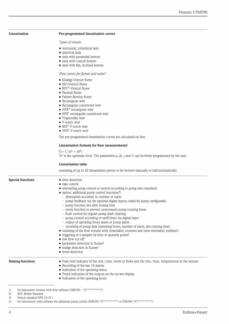
Linearisation Pre-programmed linearisation curves
Types of vessels
• horizontal, cylindrical tank
• spherical tank
• tank with pyramidal bottom
• tank with conical bottom
• tank with flat, inclined bottom
Flow curves for flumes and weirs1)
• Khafagi-Venturi flume
• ISO-Venturi flume
• BST2)-Venturi flume
• Parshall flume
• Palmer-Bowlus flume
• Rectangular weir
• Rectangular constricted weir
• NFX3) rectangular weir
• NFX rectangular constricted weir
• Trapezoidal weir
• V-notch weir
• BST V-notch wier
• NFX V-notch weir
The pre-programmed linearisation curves are calculated on-line.
Linearisation formula for flow measurements
Q = C (h + h)"h" is the upstream level. The parameters , , and C can be freely programmed by the user.
Linearisation table
consisting of up to 32 linearisation points; to be entered manually or half-automatically.
Special functions • limit detection
• rake control
• alternating pump control or control according to pump rate (standard)
• option: additional pump control functions4):
– Alternation accordint to runtime or starts
– pump feedback via the optional digital inputs; stand-by pump configurable
– pump function test after resting time
– storm function to prevent unnecessary pump running times
– flush control for regular pump shaft cleaning
– pump control according to tariff times via digital input
– output of operating hours alarm or pump alarm
– recording of pump data (operating hours, number of starts, last running time)
• totalising of the flow volume with (resettable) counters and (non-resettable) totalisers
• triggering of a sampler by time or quantity pulses
• low flow cut off
• backwater detection in flumes
• sludge detection in flumes
• trend detection
Datalog functions • Peak hold indicator of the min./max. levels or flows and the min./max. temperatures at the sensors
• Recording of the last 10 alarms
• Indication of the operating status
• Trend indication of the outputs on the on-site display
• Indication of the operating hours
1) for instrument versions with flow software (FMU90 - *2**********)
2) BST: British Standard
3) French standard NFX 10-311
4) for instruments with software for additional pump control (FMU90-*3********** or FMU90-*4**********)
Prosonic S FMU90
Endress+Hauser 5
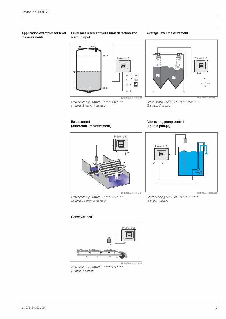
Application examples for level
measurements
Level measurement with limit detection and
alarm output
L00-FMU90xxx-15-00-00-xx-010
Order code e.g.: FMU90 - *1***131****
(1 input, 3 relays, 1 outputs)
Average level measurement
L00-FMU90xxx-15-00-00-xx-003
Order code e.g.: FMU90 - *1***212****
(2 inputs, 2 outputs)
min
Prosonic S
max
min
L
FDU9x
L
max
Prosonic S
L1 + L22
L1L2
Rake control
(differential measurement)
L00-FMU90xxx-15-00-00-xx-004
Order code e.g.: FMU90 - *1***212****
(2 inputs, 1 relay, 2 outputs)
Alternating pump control
(up to 6 pumps)
L00-FMU90xxx-15-00-00-xx-007
Order code e.g.: FMU90 - *1***131****
(1 input, 3 relays)
Prosonic S
D1
D2 ML
Prosonic S
Conveyor belt
L00-FMU90xxx-15-00-00-xx-005
Order code e.g.: FMU90 - *1***111****
(1 input, 1 output)
D
Prosonic S
Prosonic S FMU90
6 Endress+Hauser
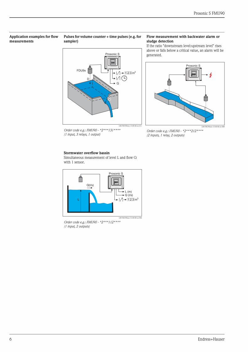
Application examples for flow
measurements
Pulses for volume counter + time pulses (e.g. for
sampler)
L00-FMU90xxx-15-00-00-xx-011
Order code e.g.: FMU90 - *2***131****
(1 input, 3 relays, 1 output)
Flow measurement with backwater alarm or
sludge detection
If the ratio "downstream level:upstream level" rises
above or falls below a critical value, an alarm will be
generated.
L00-FMU90xxx-15-00-00-xx-008
Order code e.g.: FMU90 - *2***212****
(2 inputs, 1 relay, 2 outputs)
FDU9x
D
Q
Prosonic S
1 2 3 m3
Q
Prosonic S
Stormwater overflow bassin
Simultaneous measurement of level L and flow Q
with 1 sensor.
L00-FMU90xxx-15-00-00-xx-006
Order code e.g.: FMU90 - *2***112****
(1 input, 2 outputs)
L
Q(l/s)
L (m)Q (l/s)
Prosonic S
1 2 3 m3

Prosonic S FMU90
Endress+Hauser 7
System integration HART Operating options
In the standard version a HART signal is superimposed onto the first output current. In order to use the HART
communication, the circuit must contain a communication resistor of 250.
L00-FMU90xxx-14-00-00-xx-020
1 SPS, PLC, API 5 Operating and display module at the Prosonic S (if present)
2 Commubox FXA195 (USB), HART-Protocol 6 Field Xpert SFX100
3 FieldCare 7 VIATOR Bluetooth-Modem with connection cable
4 Commubox FXA291 (service interface)
System integration
PROFIBUS DP
Operating options
• via the display and operating module at the Prosonic S
• via the service interface with the Commubox FXA291 and the operating program FieldCare
• via PROFIBUS DP with Profiboard or Proficard and the operating program FieldCare
L00-FMU90xxx-14-00-00-xx-021
250 � I : 4...20 mA + HART1
5
4
31
2
7 6
PROFIBUS DP
SPS /PLC/API
Ethernet
PDM...
Prosonic S
PROFIboardPROFIcardPROFIusb
CommuboxFXA 291
FieldCare
TT
FieldCare

Prosonic S FMU90
8 Endress+Hauser
Input
Sensor inputs Depending on the instrument version, 1 or 2 of the sensors FDU90, FDU91, FDU91F, FDU92, FDU93, FDU95
and FDU96 can be connected. The Prosonic S identifies these sensors automatically.
In order to support existing installations, the sensors of the series FDU8x can be connected as well. The type
of sensor must be entered manually.
Warning!
The sensors FDU83, FDU84, FDU85 and FDU86 with an ATEX, FM or CSA certificate are not certified for
connection to the transmitter FMU90.
External limit switches
(option)
Optionally, the Prosonic S FMU90 has four inputs for external limit switches (FMU90-********B***).
Switching options
• external passive limit switch (NC/NO switch)
• 0: < 8 V; 1: > 16 V
Usage (examples)
• pump feedback (for FMU90-*3******B***) and FMU90-*4******B***)
• pump tariff control (for FMU90-*3******B***) and FMU90-*4******B***)
• start/stop/reset of daily counters (for flow measurements)
(for FMU90-*2******B*** and FMU90-*4******B***)
• min/max level detection, e.g. by Liquiphant
External temperature sensor Optionally, the Prosonic S FMU90 has an input for an external temperature sensor (FMU90-********B***).
Connectable sensors
• Pt100 (3-wire or 4-wire connection)
A Pt100 with 2-wire connection may not be used due to its insufficient accuracy.
• FMT131(from Endress+Hauser, ä 29, "Accessories")
Usage (example)
• Time-of-flight correction for a heated sensor (FDU90-***B*, FDU91-***B*).
Sensor FDU90FDU91
FDU91FFDU92 FDU93 FDU95 FDU96
max. range1) in liquids
1) This table gives the maximum range. The range depends on the measuring conditions. For an estimation see
Technical Information TI00396F, chapter "Input".
3 (9.8) 10 (33) 20 (66) 25 (82) - -
max. range1 in solids 1.2 (3.9) 5 (16) 10 (33) 15 (49) 45 (148) 70 (230)
m (ft)
SensorFDU80
FDU80F
FDU81
FDU81FFDU82 FDU83 FDU84 FDU85 FDU86
max. range1) in liquids
1) This table gives the maximum range. The range depends on the measuring conditions. For an estimation see
Technical Information TI 189F, chapter "Planning Recommendations".
5 (16) 10 (33) 20 (66) 25 (82) - - -
max. range1 in solids 2 (6.6) 5 (16) 10 (33) 15 (49) 25 (82) 45 (148) 70 (230)
m (ft)

Prosonic S FMU90
Endress+Hauser 9
Output
Analogue outputs
Relay outputs
Number 1 or 2, depending on instrument version
Output signal configurable at the instrument:
• 4 to 20 mA with HART1)
• 0 to 20 mA without HART
1) The HART signal is assigned to the first analogue output. The second analogue output does not carry a HART signal.
Signal on alarm • for setting 4 to 20 mA, selectable:
– -10% (3,6 mA)
– 110% (22 mA)
– HOLD (last current value is held)
– user specific
• for setting 0 to 20 mA:
– 110% (21,6 mA)
– HOLD (last current value is held)
– user specific
Output damping freely selectable, 0 to 1000 s
Load max. 600 , influence negligible
max. ripple USS = 200 mV at 47 to 125 Hz (measured at 500)
max. noise Ueff = 2,2 mV at 500 Hzto 10 kHz (measured at 500)
Number 1, 3 or 6; depending on the instrument version
Type potential-free relay, SPDT, can be inverted
Assignable functions • limit (inband, out-of-band, trend, level limit)
• counting pulse for flow counting (max. frequency 2 Hz; pulse width adjustable)
• time pulse (max. frequency 2 Hz; pulse width adjustable)
• alarm/diagnosis
(e.g. indication of backwater1), sludge, echo loss etc.)
• pump control (alternating/fixed limit/pump rate)
• for FMU90-*3********** and FMU90-*4**********):
additional pump control (standby pump, storm function to avoid unnecessary run
times of the pumps, pump function test, flush control to clean pump shafts, operating
hours alarm, pump alarm)
• rake control (difference or relative measurement)
• fieldbus relay (to be switched direclty from the PROFIBUS DP-bus)
1) for instrument versions with flow software (FMU90 - *2**********)
Switching power • DC voltage: 35 VDC, 100 W
• AC voltage: 4 A, 250 V, 100 VA at cos = 0,7
State on error selectable:
• HOLD (last value is held)
• energized
• de-energized
• present value is used
Behaviour after power failure switch-on delay selectable
LEDs2)
2) for instrument versions with display and operating module
A yellow LED on the front panel is allocated to each relay, which lights if the relay is
energized.
The LED of an alarm relay lights during normal operation.
The LED for a pulse relay briefly flashes at every pulse.

Prosonic S FMU90
10 Endress+Hauser
PROFIBUS DP interface
Power supply
Supply voltage/
Power consumption/
Current consumption
Galvanic isolation The following terminals are galvanically isolated from each other:
• auxiliary energy
• sensor inputs
• analogue output 1
• analogue output 2
• relay outputs
• bus connection (PROFIBUS DP)
Fuse • 2 A T /DC
• 400 mA T /AC
accesible in the terminal compartment
Profile 3.0
Transmittable values • main value (level or flow, depending on the instrument version)
• distances
• counters
• temperatures
• average/difference/sum
• relay states
• rake control
• pump control
Function blocks • 10 Analog Input Blocks (AI)
• 10 Digital Input Blocks (DI)
• 10 Digital Output Blocks (DO)
Supported baud rates • 9.6 kbaud
• 19.2 kbaud
• 45,45 kbaud
• 93.75 kbaud
• 187.5 kbaud
• 500 kbaud
• 1.5 Mbaud
• 3 Mbaud
• 6 Mbaud
• 12 Mbaud
Service Access Points (SAPs) 1
ID number 1540 (hex) 1540 (hex) = 5440 (dec)
GSD file EH3x1540.gsd
Addressing Via dip switches at the instrument or via software (e.g. FieldCare).
Default address: 126 per software
Termination Can be activated/deactivated in the instrument.
Locking The device can be locked by hardware or software.
Instrument version Supply voltage Power consumption Current consumption
AC voltage
(FMU90 - ****A****)90 to 253 VAC (50/60 Hz) max. 23 VA max. 100 mA at 230 VAC
DC voltage
(FMU90 - ****B****)10,5 to 32 VDC max. 14 W (typically 8 W) max. 580 mA at 24 VDC
Prosonic S FMU90
Endress+Hauser 11
Electrical connection
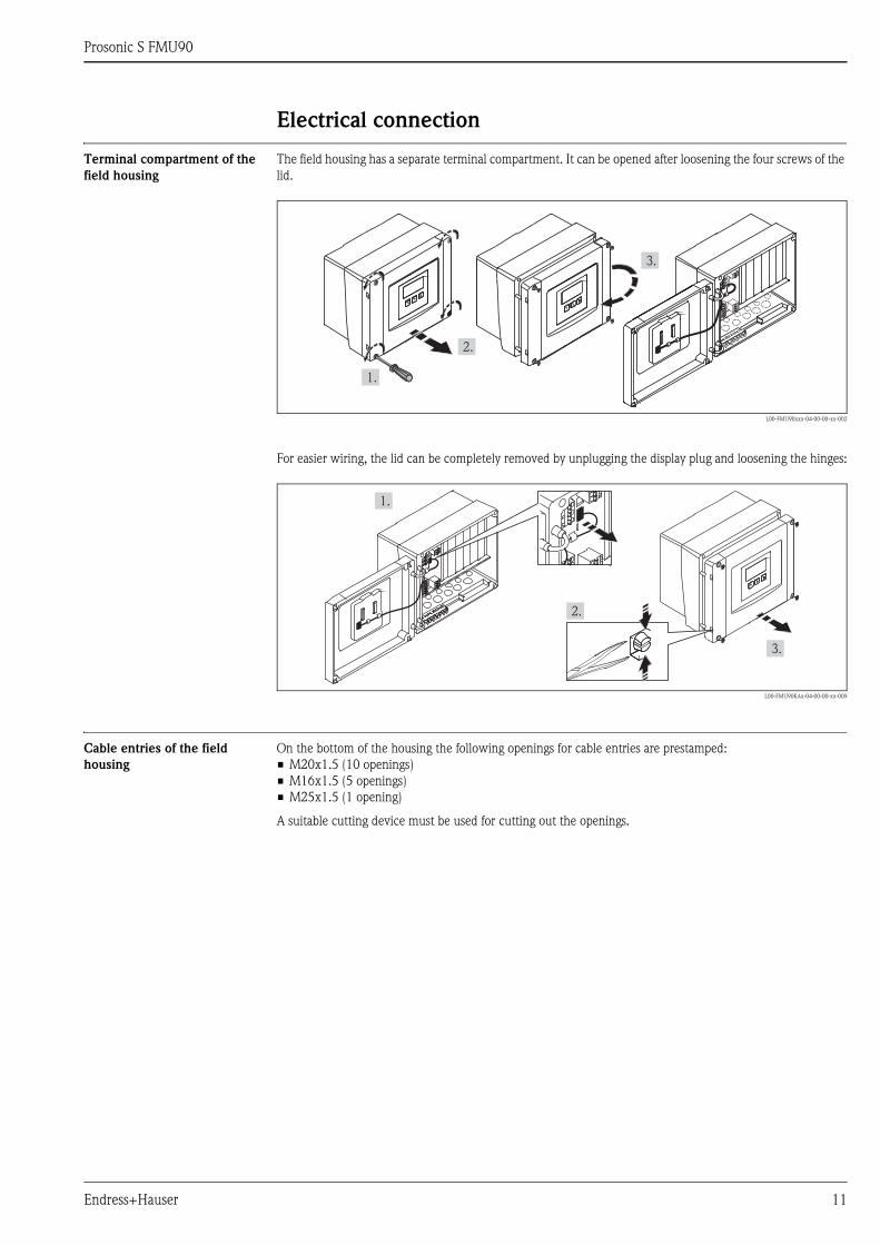
Terminal compartment of the
field housing
The field housing has a separate terminal compartment. It can be opened after loosening the four screws of the
lid.
L00-FMU90xxx-04-00-00-xx-002
For easier wiring, the lid can be completely removed by unplugging the display plug and loosening the hinges:
L00-FMU90KAx-04-00-00-xx-009
Cable entries of the field
housing
On the bottom of the housing the following openings for cable entries are prestamped:
• M20x1.5 (10 openings)
• M16x1.5 (5 openings)
• M25x1.5 (1 opening)
A suitable cutting device must be used for cutting out the openings.
1.
2.
3.
1.
2.
Prosonic S FMU90
12 Endress+Hauser
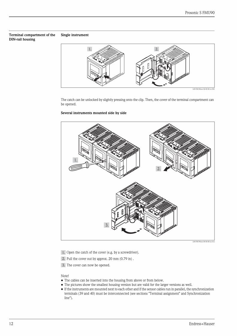
Terminal compartment of the
DIN-rail housing
Single instrument
L00-FMU90xxx-04-00-00-xx-003
The catch can be unlocked by slightly pressing onto the clip. Then, the cover of the terminal compartment can
be opened.
Several instruments mounted side by side
L00-FMU90xxx-04-00-00-xx-012
Open the catch of the cover (e.g. by a screwdriver).
Pull the cover out by approx. 20 mm (0.79 in) .
The cover can now be opened.
Note!
• The cables can be inserted into the housing from above or from below.
• The pictures show the smallest housing version but are valid for the larger versions as well.
• If the instruments are mounted next to each other and if the sensor cables run in parallel, the synchronization
terminals (39 and 40) must be interconnected (see sections "Terminal assignment" and Synchronization
line").
1. 2.
1.
2.
3.
1.
2.
3.
Prosonic S FMU90
Endress+Hauser 13
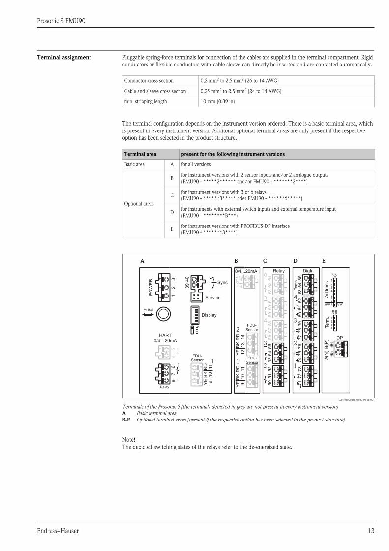
Terminal assignment Pluggable spring-force terminals for connection of the cables are supplied in the terminal compartment. Rigid
conductors or flexible conductors with cable sleeve can directly be inserted and are contacted automatically.
The terminal configuration depends on the instrument version ordered. There is a basic terminal area, which
is present in every instrument version. Additonal optional terminal areas are only present if the respective
option has been selected in the product structure.
L00-FMU90xxx-04-00-00-xx-001
Terminals of the Prosonic S (the terminals depicted in grey are not present in every instrument version)
A Basic terminal area
B-E Optional terminal areas (present if the respective option has been selected in the product structure)
Note!
The depicted switching states of the relays refer to the de-energized state.
Conductor cross section 0,2 mm2 to 2,5 mm2 (26 to 14 AWG)
Cable and sleeve cross section 0,25 mm2 to 2,5 mm2 (24 to 14 AWG)
min. stripping length 10 mm (0.39 in)
Terminal area present for the following instrument versions
Basic area A for all versions
Optional areas
Bfor instrument versions with 2 sensor inputs and/or 2 analogue outputs
(FMU90 - *****2****** and/or FMU90 - *******2****)
Cfor instrument versions with 3 or 6 relays
(FMU90 - ******3***** oder FMU90 - ******6*****)
Dfor instruments with external switch inputs and external temperature input
(FMU90 - ********B***)
Efor instrument versions with PROFIBUS DP interface
(FMU90 - *******3****)
FDU-Sensor
0/4...20mA
1
42
41
Relay55
52
54
51
53
50
3
Addre
ss
Term
.
DPoff
on
off
on
SWHW
12345678
1234
A(N
)
66
B(P
)
65
Display
PO
WE
R
HART0/4…20mA
Sync
Fuse
I1FDU-
Sensor
RD
11
BK
10
YE 9
40
39
54
67
8
11
Service
Relay
32
1
A B C E
2
58
57
56
4
61
60
59
5
64
63
62
6
RD
11
BK
10
YE 9
2
RD
14
BK
13
YE
12
I2
FDU-Sensor
DigIn
76
73
75
72
74
71
2
D
1
79
78
77
3
82
81
80
485
84
83T
em
p.

Prosonic S FMU90
14 Endress+Hauser
Terminals Meaning Terminal area Remarks
Auxiliary energy
1, 2• L (für AC version)
• L+ (for DC version)A depending on instrument version:
• 90 to 253 VAC
• 10,5 to 32 VDC2 • N (for AC version)
• L- (for DC version)
A
3 Potential equalization A
Fuse A depending on instrument version:
• 400 mA T (for AC)
• 2 A T (for DC)
Analog outputs (not available for PROFIBUS DP instruments)
4, 5
Analog output 1;
4 to 20 mA with HART/
0 to 20 mA w/o HART
A not present for the PROFIBUS DP version
41, 42
Analog output 2 (optional);
4 to 20 mA/
0 to 20 mA
Bonly for the version with two analog outputs;
no HART signal at this output
Relay outputs
6, 7, 8 Relay 1 A
50, 51, 52 Relay 2 (optional) C only for the versions with 3 or 6 relays
53, 54, 55 Relay 3 (optional) C only for the versions with 3 or 6 relays
56, 57, 58 Relay 4 (optional) C only for the version with 6 relays
59, 60, 61 Relay 5 (optional) C only for the version with 6 relays
62, 63, 64 Relay 6 (optional) C only for the version with 6 relays
Bus communication (only available for PROFIBUS DP instruments)
65 PROFIBUS A (RxT/TxD - N) Donly for the PROFIBUS DP version
66 PROFIBUS B (RxT/TxD - P) D
Synchronization
39, 40 Synchronization A see section 4.6, "Synchronization line"
Level inputs
9 (YE),
10 (BK),
11 (RD)
Sensor 1 (FDU8x/9x)
YE: yellow strand
BK: black strand
RD: red strand
• A: for versions with 1 sensor input
• B: for versions with 2 sensor inputs1)
12 (YE),
13 (BK),
14 (RD)
Sensor 2 (FDU8x/9x) (optional)
YE: yellow strand
BK: black strand
RD: red strand
B only for the version with 2 sensor inputs
external switch inputs
71, 72, 73 external switch input 1 D 0: < 8 V or 72 and 73 interconnected
1: > 16 V or 72 and 73 not interconnected
74, 75, 76 external switch input 2 D 0: < 8 V or 75 and 76 interconnected
1: > 16 V or 75 and 76 not interconnected
77, 78, 79 external switch input 3 D 0: < 8 V or 78 and 79 interconnected
1: > 16 V or 78 and 79 not interconnected
80, 81, 82 external switch input 4 D 0: < 8 V or 81 and 82 interconnected
1: > 16 V or 81 and 82 not interconnected
temperature input
83, 84, 85 temperature input:
• PT100
• FMT131 (Endress+Hauser)
D see section
"Connection of a temperature sensor"

Prosonic S FMU90
Endress+Hauser 15
Warning!
When using the public supply mains, an easily accesible power switch must be installed in the proximity of the
device. The power switch must be marked as a disconnector for the device (IEC/EN 61010).
Note!
• In order to avoid interference signals, the sensor cables should not be laid parallel to high voltage or electric
power lines.
• The cables may not be laid in the proximity to frequency converters.
Additional elements on the terminal areas
1) In this case, terminals 9/10/11 are not present on terminal area A.
Designation Meaning/Remarks
Fuse Fuse: 2 A T /DC or 400 mA T/AC
Display Connection of the display or the remote display and operating module
Service Service interface for connection of a PC/Notebook via Commubox FXA291
Locking switch
Term. Bus termination (only applicable for instruments with PROFIBUS interface)
Address Bus address (only applicable for instruments with PROFIBUS interface)
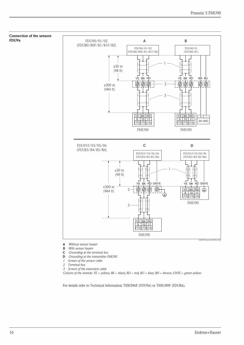
Prosonic S FMU90
16 Endress+Hauser
Connection of the sensors
FDU9x
L00-FDU9xxxx-04-00-00-xx-002
A Without sensor heater
B With sensor heater
C Grounding at the terminal box
D Grounding at the transmitter FMU90
1 Screen of the sensor cable
2 Terminal box
3 Screen of the extension cable
Colours of the strands: YE = yellow; BK = black; RD = red; BU = blue; BN = brown; GNYE = green-yellow
For details refer to Technical Information TI00396F (FDU9x) or TI00189F (FDU8x).
YE9
(12)
BK10
(13)
RD11
(14)
FDU90/91/92(FDU80/80F/81/81F/82)
BKYE RD
1
YE9
(12)
BK10
(13)
RD11
(14)
FDU91F/93/95/96(FDU83/84/85/86)
BKYE RD GNYE
2
3
FMU90
2
3
FMU90
YE9
(12)
BK10
(13)
RD11
(14)
FDU90/91(FDU80/81)
BKYE RD
FMU90
BN BU
24 VDC
+ -
A B
C
YE9
(12)
BK10
(13)
RD11
(14)
FDU91F/93/95/96(FDU83/84/85/86)
BKYE RD GNYE
FMU90
D
FDU90/91/92(FDU80/80F/81/81F/82)
FDU91F/93/95/96(FDU83/84/85/86)
300 m(984 ft)≤
≤30 m(98 ft)
1
300 m(984 ft)≤
≤30 m(98 ft)

Prosonic S FMU90
Endress+Hauser 17
Synchronization line
Connection of the separate
display and operating module
L00-FMU90xxx-04-00-00-xx-005
1 Connection of the display plug with the cable (3 m (9.8 ft))
For the version of the Prosonic S with a separate display for panel mounting, a pre-assembled connecting cable
(3 m (9.8 ft)) is supplied. The cable must be connected to the display plug of the Prosonic S.
Note!
Minimum diameter for cable bushing: 20 mm (0.79 in)
• If wiring several Prosonic S (FMU90/FMU95)
which are mounted in a common cabinet and if the
sensor cables run in parallel, the synchronization
terminals (39 and 40) must be interconnected.
• Up to 20 instruments can be synchronized in this
way.
• The synchronization causes the evaluation units
FMU9x to send the pulses simultaneously. Only
after all sensors have received their signal, new
simultaneous pulses are sent. This prevents pulses
in the sensor cable of one sensor from influencing
the received signal on the cable of a different
sensor.
• If there are more than 20 instruments, groups must
be formed, each containing a maximum of 20
instruments. For the instruments within each
group, the sensor cables may run in parallel. The
sensor cables of different groups must be seperated
from each other.
• Usual commercial screened cable can be used for
synchronization
– max. length: 10 m (33 ft) between the individual
instruments
– cross section: 2 x (0.75 to 2.5 mm2
(18 to 14 AWG))
– for lengths up to 1 m (3.3 ft), an unscreened
cable can be used; for lenghts exceeding 1 m
(3.3 ft), screening is required. The screen must
be connected to ground
• Instruments of the Prosonic FMU86x family can be
connected to the synchronization line as well. In
this case a maximum of 10 instruments can be
connected to each synchronisation line.
L00-FMU90xxx-04-00-00-xx-004
L00-FMU90xxx-04-00-00-xx-017
Prosonic SFMU90/95
39 40
1 2 3 20……
FMU90 FMU90 FMU90
Prosonic SFMU90/95
39 40
Prosonic SFMU90/95
39 40
Prosonic SFMU90/95
39 40
ProsonicFMU860/861/862
63 64
1 2 10……
FMU90
V H
Display
PO
WE
R
HART0/4…20mA
Sync
Fuse
I1 FDU-Sensor
RD
11
BK
10
YE 9
40
39
54
67
8
Service
Relay
32
1 1

Prosonic S FMU90
18 Endress+Hauser
Connection of external swit-
ches
(for FMU90-********B***)
L00-FMU90xxx-04-00-00-xx-021a
A Liquiphant
B External switch
C External switch with external supply voltage
The maximum short-circuit current at 24 V is 20 mA.
Connection of a temperature
sensor
The Prosonic S FMU90 transmitter has an optional input for an external temperature probe (in the product
structure: feature 90 "Additional input", option B, ä 28). The following probes can be connected:
• a FMT131 temperature probe from Endress+Hauser
• a Pt100 temperature probe
Note!
• After connecting an external temperature sensor, the following is required:
1. The type of the connected sensor (Pt100 or FMT131) must be selected in "sensor management/ext.
temp. sensor" in the "sensor type" parameter.
2. The external temperature sensor must be assigned to an ultrasonic sensor in "sensor management/FDU
sensor/US sensor N" in the "temp. measurement" parameter.
• If the option "alarm" has been selected for the case of an error in external temperature sensor, this alarm is
indicated by the alarm relay.
PNP
FMU90 FMU90
FTL
A B
FMU90
C
24 V
(24 V)
71 72 73
74 75 76
77 78 79
80 81 82
(24 V)
71 72 73
74 75 76
77 78 79
80 81 82
(24 V)
71 72 73
74 75 76
77 78 79
80 81 82

Prosonic S FMU90
Endress+Hauser 19
FMT131 (Endress+Hauser)
(connectable to FMU90-********B***)
L00-FMU90xxx-04-00-00-xx-019
A Non-Ex area (FMT131-R) BK black
B Ex area (FMT131-J) with grounding in the FMU90 YE yellow
C Ex area (FMT131-J) with grounding at a terminal box YEGN yellow-green
Note!
For details refer to the Operating Instructions KA00019F.
Pt100
(connectable to FMU90-********B***)
L00-FMU90xxx-04-00-00-xx-020
A Pt100 with 3-wire connection
B Pt100 with 4-wire connection (one connector remains unused)
Note!
A Pt100 with 2-wire connection may not be used due to its insufficient measuring accuracy.
Warning!
A Pt100 may not be connected in explosion hazardous areas. A FMT131 must be used instead.
83 84
BK YE
FMU9085
YEGN
EX
EX
FMT131-J
EX
EX83 84
BK
BK
YE
YE
YEGN
FMT131-J
FMU90
85
EX
EX
83 84
BK
BK
YE
YE
YEGN
FMT131-R
FMU9085
A CB
83 84 85A
Pt100
83 84
FMU90
85
Pt100
B

Prosonic S FMU90
20 Endress+Hauser
Performance characteristics
Reference operating
conditions
• Temperature = 24±5 °C (75±9 °F)
• Pressure = 960±100 mbar (14±1.45 psi)
• Relative humidity = 60±15 %
• Ideally reflecting surface, sensor vertically aligned
(e.g. calm, plane liquid surface of 1 m2 (10.76 ft2))
• No interference echoes within the signal beam
• Settings of the application parameters:
– tank shape = flat ceiling
– medium property = liquid
– process condition = calm surface
Measuring uncertainty5) ±0.2 % of the maximum span of the sensor
Typical accuracy6) ±2 mm (0.08 in) + 0.17 % of the measured distance
Measured value resolution 1 mm (0.04 in) with FDU90/FDU91
Measuring frequency max. 3 Hz
The exact value depends on the settings of the application parameters and the instrument version.
Note!
The maximum measuring frequency is obtained for "empty E" 2 m ( 6.6 ft) and "process condition" = "test:
no filter".
Influence of the vapor
pressure
The vapor pressure at 20 °C (68 °F) gives a hint on the accuracy of the ultrasonic level measurement. If the
vapor pressure at 20 °C (68 °F) is below 50 mbar (1 psi), ultrasonic level measurement is possible with a very
high accuracy. This is valid for water, aqueous solutions, water-solid-solutions, dilute acids (hydrochloric acid,
sulfuric acid, ...), dilute bases (caustic soda, ...), oils, greases, slurries, pastes, ...
High vapor pressures or outgassing media (ethanol, acetone, ammonia, ...) can influence the accuracy. If
conditions like these are present, please contact your Endress+Hauser sales representative.
5) according to NAMUR EN 61298-2
6) after calibration
Prosonic S FMU90
Endress+Hauser 21
Environment
Ambient temperature -40 to 60 °C (-40 to 140 °F)
The functionality of the LC display becomes restricted at TU < -20 °C ( TU < -4 °F).
If the device is operated outdoors in strong sunlight, a protective cover should be used ( ä 29).
Storage temperature -40 to 60 °C (-40 to 140 °F)
Climate class • Field housing: according to DIN EN 60721-3 4K2/4K5/4K6/4Z2/4Z5/4C3/4S4/4M2
(DIN 60721-3 4K2 corresponds to DIN 60654-1 D1)
• Housing for DIN rail mounting: according to
DIN EN 60721-3 3K3/3Z2/3Z5/3B1/3C2/3S3/3M1
(DIN 60721-3 3K3 corresponds to DIN 60654-1 B2)
Vibration resistance • Housing for DIN rail: DIN EN 60068-2-64 / IEC 68-2-64; 20 to 2000 Hz; 0,5 (m/s2)2/Hz
• Field housing: DIN EN 60068-2-64 / IEC 68-2-64; 20 to 2000 Hz; 1,0 (m/s2)2/Hz
Ingress protection • Field housing: IP66 / NEMA 4x
• Housing for DIN rail: IP20
• separate display:
– IP65 / NEMA 4 (front panel, if mounted in cabinet door)
– IP20 (rear panel, if mounted in cabinet door)
Electromagnetic compatibility
(EMC)
Electromagnetic compatibility according to all relevant requirements of the EN 61326- series and NAMUR
recommendation EMC (NE21). For details see declaration of conformity.
With respect to interference emission the devices meet the requirements of class A and are only provided for
use in an "industrial environment"!

Prosonic S FMU90
22 Endress+Hauser
Mechanical construction
Housing versions • Field housing; optionally with integrated display and operating module
• Housing for top-hat rail mounting; optionally with intergrated display and operating module
• Housing for top-hat rail mounting with separated display and operating module for cabinet door mounting
Dimensions of the field
housing
L00-FMU90xxx-06-00-00-xx-001
Dimensions in mm (in)
A Mounting help (supplied); can also be used as drilling template
B Field housing
C Minimum mounting distance
The dimensions of the field housing are the same for all instrument versions.
To open the housing, a minimum mounting distance of 55 mm (2.17 in) is required on the left.
Note!
The mounting help must be mounted on a plane surface and must not become bent. Otherwise the mounting
of the field housing may be difficult or impossible.
215 (8.46)
18
0(7
.09
)
150 (5.91)
15
(0.5
9)
17
0(6
.69
)
19
0(7
.48
)
80
(3.15)
100
(3.94)
ø6.5 (0.26)1
0(0
.39
)
A B
�1,6 kg (3.53 lbs)
153 (6.02)
C
�55 (2.17)�55 (2.17)
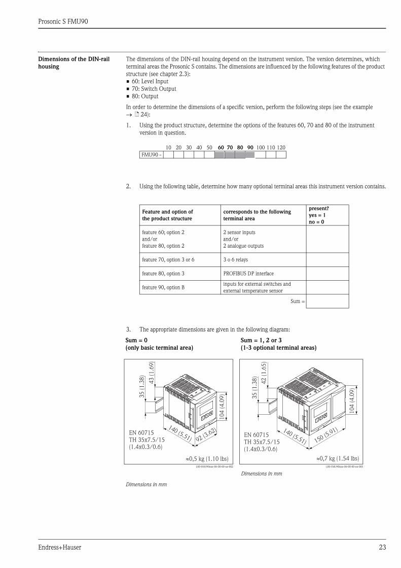
Prosonic S FMU90
Endress+Hauser 23
Dimensions of the DIN-rail
housing
The dimensions of the DIN-rail housing depend on the instrument version. The version determines, which
terminal areas the Prosonic S contains. The dimensions are influenced by the following features of the product
structure (see chapter 2.3):
• 60: Level Input
• 70: Switch Output
• 80: Output
In order to determine the dimensions of a specific version, perform the following steps (see the example
ä 24):
1. Using the product structure, determine the options of the features 60, 70 and 80 of the instrument
version in question.
2. Using the following table, determine how many optional terminal areas this instrument version contains.
3. The appropriate dimensions are given in the following diagram:
10 20 30 40 50 60 70 80 90 100 110 120
FMU90 -
Feature and option of
the product structure
corresponds to the following
terminal area
present?
yes = 1
no = 0
feature 60; option 2
and/or
feature 80, option 2
2 sensor inputs
and/or
2 analogue outputs
feature 70, option 3 or 6 3 o 6 relays
feature 80, option 3 PROFIBUS DP interface
feature 90, option Binputs for external switches and
external temperature sensor
Sum =
Sum = 0
(only basic terminal area)
L00-FMU90xxx-06-00-00-xx-002
Dimensions in mm
Sum = 1, 2 or 3
(1-3 optional terminal areas)
L00-FMU90xxx-06-00-00-xx-005
Dimensions in mm
92 (3.62)
10
4(4
.09
)
140 (5.51)
43
(1.6
9)
EN 60715TH 35x7.5/15(1.4x0.3/0.6)
35
(1.3
8)
0,5 kg (1.10 lbs)�
150 (5.91)
10
4(4
.09
)
140 (5.51)EN 60715TH 35x7.5/15(1.4x0.3/0.6)
35
(1.3
8)
�0,7 kg (1.54 lbs)
42
(1.6
5)
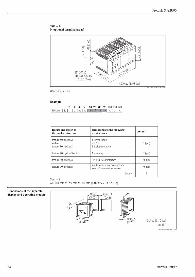
Prosonic S FMU90
24 Endress+Hauser
Example
Sum = 2
=> 104 mm x 150 mm x 140 mm (4.09 x 5.91 x 5.51 in)
Dimensions of the separate
display and operating module
L00-FMU90xxx-06-00-00-xx-004
Sum = 4
(4 optional terminal areas)
L00-FMU90xxx-06-00-00-xx-009
Dimensions in mm
210 (8.27)140 (5.51)
EN 60715TH 35x7.5/15(1.4x0.3/0.6)
35
(1.3
8)
�0,9 kg (1.98 lbs)
42
(1.6
5)
10
4(4
.09
)
10 20 30 40 50 60 70 80 90 100 110 120
FMU90 - R 1 2 A A A 1 A
feature and option of
the product structure
corresponds to the following
terminal areapresent?
feature 60; option 2
and/or
feature 80, option 2
2 sensor inputs
and/or
2 analogue outputs
1 (yes)
feature 70, option 3 or 6 3 or 6 relays 1 (yes)
feature 80, option 3 PROFIBUS DP interface 0 (no)
feature 90, option Binputs for external switches and
external temperature sensorr0 (no)
Sum = 2
2 3 2 A
96
55
max. 6
92 min. 11
~0,5 kg (1.10 lbs)
(0.43)(3.62)
(0.24)(3.78)
(2.17)
mm (in)

Prosonic S FMU90
Endress+Hauser 25
Weight
Materials
L00-FMU90xxx-06-00-00-xx-001
Housing version Weight
Field housing approx. 1.6 to 1.8 kg (3.53 to 3.97 lbs); depending on instrument version
Housing for DIN rail approx. 0.5 to 0.7 kg (1.10 to 1.54 lbs); depending on instrument version
( ä 23 "Dimensions of the DIN-rail housing")
separate display and operating
moduleapprox. 0.5 kg (1.10 lbs)
Pos. Part Material
1 Housing bracket PC-FR
2 Field housing PC-FR
3 Housing for DIN rail PBT-GF
4 Separate display and operating module PC
5 Sealing PUR foam
6 Nameplate Polyester
7 Screws A4 (1.4578)
1
76
52 3
4
4
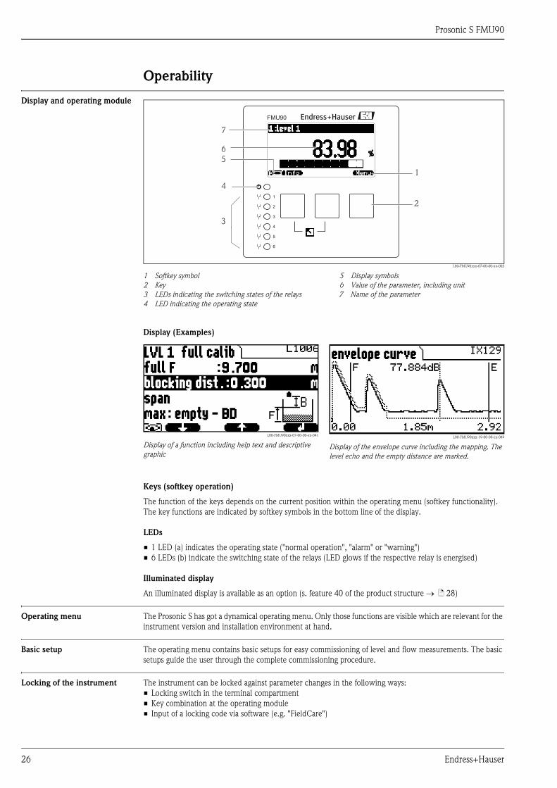
Prosonic S FMU90
26 Endress+Hauser
Operability
Display and operating module
L00-FMU90xxx-07-00-00-xx-002
1 Softkey symbol 5 Display symbols
2 Key 6 Value of the parameter, including unit
3 LEDs indicating the switching states of the relays 7 Name of the parameter
4 LED indicating the operating state
Display (Examples)
Keys (softkey operation)
The function of the keys depends on the current position within the operating menu (softkey functionality).
The key functions are indicated by softkey symbols in the bottom line of the display.
LEDs
• 1 LED (a) indicates the operating state ("normal operation", "alarm" or "warning")
• 6 LEDs (b) indicate the switching state of the relays (LED glows if the respective relay is energised)
Illuminated display
An illuminated display is available as an option (s. feature 40 of the product structure ä 28)
Operating menu The Prosonic S has got a dynamical operating menu. Only those functions are visible which are relevant for the
instrument version and installation environment at hand.
Basic setup The operating menu contains basic setups for easy commissioning of level and flow measurements. The basic
setups guide the user through the complete commissioning procedure.
Locking of the instrument The instrument can be locked against parameter changes in the following ways:
• Locking switch in the terminal compartment
• Key combination at the operating module
• Input of a locking code via software (e.g. "FieldCare")
1
2
3
4
5
6
FMU90
4
3
1
2
7
6
5
L00-FMU90xxx-07-00-00-en-041
Display of a function including help text and descriptive
graphic
L00-FMU90xxx-19-00-00-en-089
Display of the envelope curve including the mapping. The
level echo and the empty distance are marked.

Prosonic S FMU90
Endress+Hauser 27
Certificates and Approvals
CE mark The measuring system meets the legal requirements of the EC-guidelines. Endress+Hauser confirms the
instrument passing the required tests by attaching the CE-mark.
Ex approval The available certificates are listed in the ordering information. Note the associated safety instructions (XA) and
control or installation drawings (ZD).
Warning!
• Measuring systems for use in hazardous environments are accompanied by separate "Ex documentation",
which is an integral part of this Operating Manual. Strict compliance with the installation instructions and
ratings as stated in this supplementary documentation is mandatory.
– Ensure that all personnel are suitably qualified.
– Observe the specifications in the certificate as well as national and local standards and regulations.
• The transmitter may only be installed in suitable areas.
• Sensors with a certificate for hazardous areas may be connected to a transmitter without a certificate.
• For FM approvals:
Unauthorized substitution of components may impair the suitability for Division 1 or Division 2.
• Do not disconnect equipment unless the area is known to be non-hazardous.
Note!
• The sensor must be installed and used in a way that eliminates any danger. Possible installation positions: in
tanks, vessels, silos, over stockpiles, open channels, weirs or other bins.
• Sensors FDU9x with Ex-approval can be connected to the transmitter FMU90 without Ex-approval.
External standards and
guidelines
EN 60529
Protection class of housing (IP code)
EN 61326 series
EMC product family standard for electrical equipment for measurement, control and laboratory use
NAMUR
User association for automation technology in process industries
US Standard UL 61010-1
CSA General Purpose Units FMU9x-N*********** are tested according to US standard UL 61010-1, 2nd
eedition

Prosonic S FMU90
28 Endress+Hauser
Ordering information
Product structure
(*): meaning of the language code:
cs: Czech; de: German; en: English; es: Spanish; fr: French; id: Bahasa (Indonesia, Malaysia); it: Italian; ja:
Japanese; ko: korean; nl: Dutch; pl: Polish; pt: Portuguese; ru: Russian; th: Thai; zh: Chinese
010 Approval
R Non-hazarous area
J ATEX II 3D
N CSA General Purpose
020 Application
1 Level + pump control, alternating
2 Flow + totalizer + level + sample control + preprogrammed OCM flow curves
3 Level + additional pump control
4 Universal instrument (Level + Flow + Additional pump control)
030 Housing, material
1 Field mounting PC, IP66 NEMA 4x
2 DIN rail mounting PBT, IP20
040 Operation
C Illuminated display + keypad
E Illuminated display + keypad, 96x96, panel mounting, front IP65
K w/o display, via communication
050 Power supply
A 90-253 VAC
B 10.5-32 VDC
060 Level input
1 1x sensor FDU9x/8x
2 2x sensor FDU9x/8x
070 Switch output
1 1x relay, SPDT
3 3x relay, SPDT
6 6x relay, SPDT
080 Output
1 1x 0/4-20mA HART
2 2x 0/4-20mA HART
3 PROFIBUS DP
090 Additional input
A w/o additional input
B 4x limit switch + 1x temperature PT100/FMT131
100 Datalog function
A Basic version
110 Languages
1 de, en, nl, fr, es, it, pt
2 de, en, ru, pl, cs
3 en, zh, ja, ko, th, id
120 Additional option
A Basic version
L 5-point linearity protocol only to order with FDU9x sensor
+ 5-point linearity protocol
995 Marking
1 Tagging (TAG)
2 Bus address
FMU90 - complete product designation

Prosonic S FMU90
Endress+Hauser 29
Scope of delivery • Instrument according to the version ordered
• Operating program: FieldCare
• Operating Instructions (depending on communication version ä 35, "Documentation")
• for certified instrument versions: Safety Instructions (XAs) or Control Drawings (ZDs) ä 35,
"Documentation"
• field housing units for flow measurement FMU90-*21********* are delivered with 2 screws for plombing
the device
Accessories
Commubox FXA195 HART For intrinsically safe communication with FieldCare via the USB interface. For details refer to TI00404F/00/
EN.
Commubox FXA291 The Commubox FXA291 connects Endress+Hauser field instruments with CDI interface (= Endress+Hauser
Common Data Interface) to the USB interface of a personal computer or a notebook. For details refer to
TI00405C/07/EN.
Protection cover for the field
housing
Mounting plate for the field
housing
• Material: 316Ti (1.4571)
• is mounted by the mounting help of the Prosonic S
• Order-Code: 52024477
L00-FMU90xxx-06-00-00-xx-003
275 (10.8)
22
7±
1.5
(8.9
4)
194 (7.6)
mm (in)
• suited for the mounting help of the Prosonic S
• for 1" - 2" tubes
• Dimensions: 210 mm x 110 mm (8.27 x 4.33 in)
• Material: 316Ti (1.4571)
• fixing clips, screws and nuts are supplied
• Order code: 52024478
L00-FMU90xxx-00-00-00-xx-001
1 Mounting help of the field housing
1

Prosonic S FMU90
30 Endress+Hauser
Mounting bracket
L00-FMUxx-00-00-00-xx-005
Adaption plate for remote
display
Option:
• Adaption plate 160x160 mm (6.3 x 6.3 in), thickness 3 mm (0.12 in) , aluminum, opening 92x92 mm
(3.62 x 3.62 in) for remote display of the FMU90 (size of the display: 96 x 96 mm (3.78 x 3.78 in)).
• Can be used to replace the FMU86x remote display or DMU2160/2260.
• Order Code: TSPFU 0390
• Please contact your Endress+Hauser sales representative.
Height mm (in) Material Order Code
700 (27.6) galv. steel 919791-0000
700 (27.6) 316Ti (1.4571) 919791-0001
1400 (55.16) galv. steel 919791-0002
1400 (55.16) 316Ti (1.4571) 919791-0003
3.2 (0.13)
20 (0.8)
55(2.17)
10
0(3
.9)
25
(0.9
8)
70
0/1
40
0(2
7.6
/5
5.1
)
45
(1.7
7)
76
(2.9
9)
10
0(3
.94
)
20
0(7
.87
)
13
(0.5
)
ø33.7(1.3)
130 (5.12)
150 (5.91)
100(3.94)
60 (2.36)
4 (0.16)
6.5
(0.3
)mm (in)
Used to mount the remote display into the opening
(138 mm x 138 mm (5.43 x 5.43 in)) of the remote
display module of the Prosonic FMU860/861/862
(Display size: 144 x 144 mm (5.67 x 5.67 in)).
Order-Code: 52027441
Note!
The adapter plate will be mounted directly in the old
remote display of the FMU86x series. The housing of
the remote display of FMU860/861/862 is the
holder for the adapter plate and the new remote
display of the FMU90/95 in the format 96x96 mm
(3.78 x 3.78 in).
L00-FMU90xxx-00-00-00-xx-001
1 Remote display of the Prosonic S with adaption plate
2 Opening of the remote display FMU860/861/862
1
2
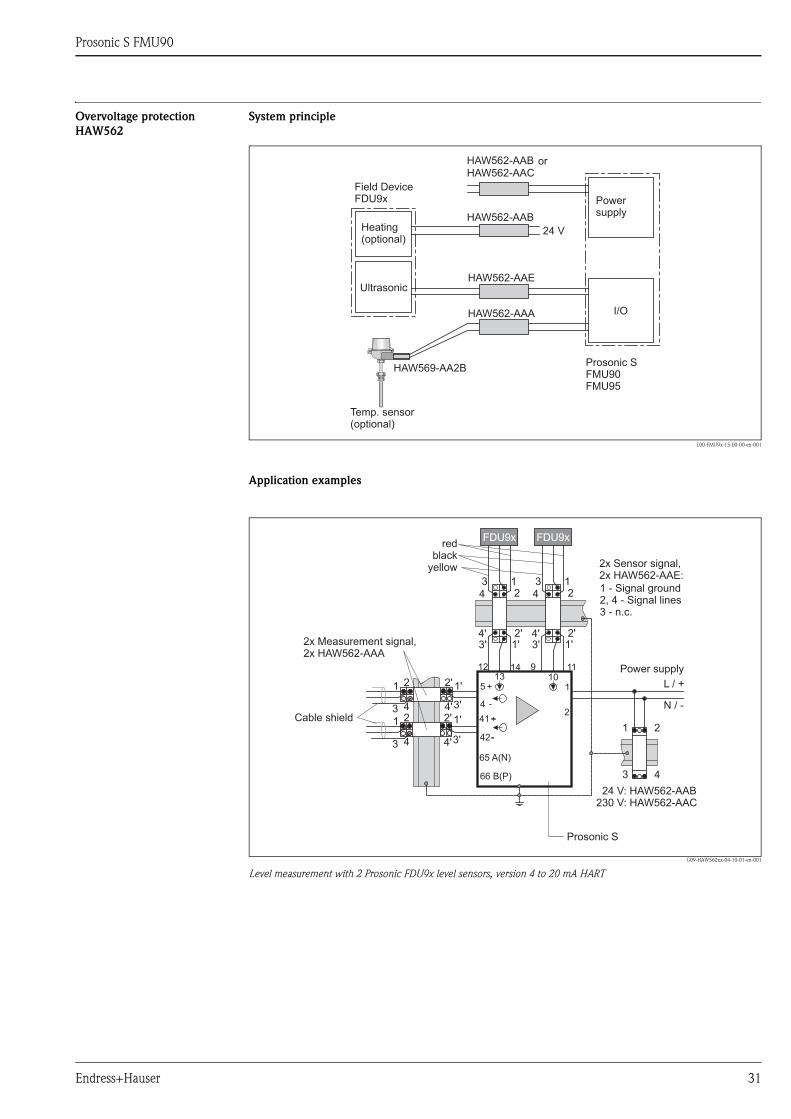
Prosonic S FMU90
Endress+Hauser 31
Overvoltage protection
HAW562
System principle
L00-FMU9x-15-00-00-en-001
Application examples
G09-HAW562xx-04-10-01-en-001
Level measurement with 2 Prosonic FDU9x level sensors, version 4 to 20 mA HART
Prosonic SFMU90FMU95
or
12 14 9 11
1
2
42
41
4
513 10
Prosonic S
L / +
N / -
FDU9xFDU9x
1'2'
3'4'
24 V: HAW562-AAB230 V: HAW562-AAC
1'2'
3'4'
1 2
3 4
1 2
3 4
12
34
1'2'
3'4'
12
34
1'2'
3'4'
1 2
3 466 B(P)
65 A(N)
2x Sensor signal,2x HAW562-AAE:
2x Measurement signal,2x HAW562-AAA
redblack
yellow
1 - Signal ground2, 4 - Signal lines3 - n.c.
Cable shield
Power supply

Prosonic S FMU90
32 Endress+Hauser
G09-HAW562xx-04-10-01-en-002
Level measurement with 1 Prosonic FDU9x level sensor, version 4 to 20 mA HART
G09-HAW562xx-04-10-01-en-003
Level measurement with 2 Prosonic FDU9x level sensors, version PROFIBUS DP
9 11
1
2
42
41
4
510
Prosonic S
L / +
N / -
FDU9x
1'2'
3'4'
24 V: HAW562-AAB230 V: HAW562-AAC
1 2
3 4
12
34
1'2'
3'4'
1 2
3 4
1x Sensor signal,1x HAW562-AAE:
1x Measurement signal,1x HAW562-AAA
redblack
yellow
1 - Signal ground2, 4 - Signal lines3 - n.c.
Cable shield
Power supply
12 14 9 11
1
2
42
41
4
513 10
L / +
N / -
24 V: HAW562-AAB230 V: HAW562-AAC
12
34
1'2'
3'4'
12
34
1'2'
3'4'
1 2
3 466 B(P)
65 A(N)1'2'
3'4'
1 2
3 4
1x PROFIBUS DP,1x HAW562-AAD
FDU9xFDU9x
Prosonic S
2x Sensor signal,2x HAW562-AAE:red
blackyellow
1 - Signal ground2, 4 - Signal lines3 - n.c.
Cable shield
Power supply

Prosonic S FMU90
Endress+Hauser 33
Ordering information
Surge Arrester HAW562, compact device for DINrail installation in signal and power supply lines
andcommunication lines protecting field devices and systems against overvoltage and magnetic induction.
For details see Technical Informations TI01012K und TI01013K and the Operating Instruction BA00306K.
Approval
AA Non-hazardous area
8D ATEX II 2 (1)G Ex ia IIC T6
Application
A Measuring signal 0/4-20 mA, PFM, PA, FF
B Supply voltage 10-55 V (+/-20%)
C Supply voltage 90-230 V (+/-10%)
D Communication RS485/MOD-Bus/PROFIBUS DP
E Protection module Prosonic FMU90
+ Additional selection (option)
Additional approvals
LA SIL
Accessory enclosed
PA Screen grounding terminal
PB Field housing
PC Mounting bracket, wall/pipe
Marking
Z1 Tagging (TAG), metal
Z3 Commissioning label, paper
Z6 Tagging (TAG), by customer
HAW562 - + complete product designation
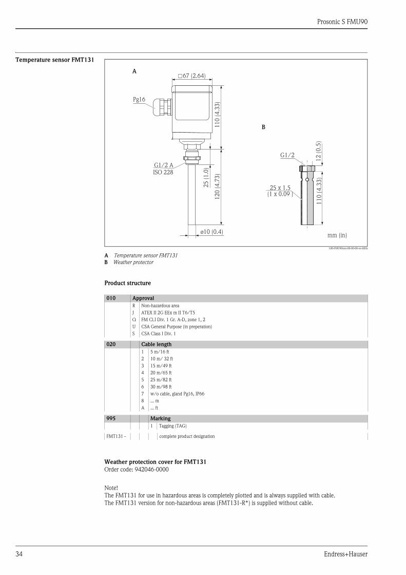
Prosonic S FMU90
34 Endress+Hauser
Temperature sensor FMT131
L00-FMU90xxx-00-00-00-xx-002a
A Temperature sensor FMT131
B Weather protector
Product structure
Weather protection cover for FMT131
Order code: 942046-0000
Note!
The FMT131 for use in hazardous areas is completely plotted and is always supplied with cable.
The FMT131 version for non-hazardous areas (FMT131-R*) is supplied without cable.
67 (2.64)
Pg16
11
0(4
.33
)1
20
(4.7
3)
ø10 (0.4)
G1/2 AISO 228
25
(1.0
)
G1/2
12
(0.5
)1
10
(4.3
3)
A
B
25 x 1.5(1 x 0.09 )
mm (in)
010 Approval
R Non-hazardous area
J ATEX II 2G EEx m II T6/T5
Q FM Cl.I Div. 1 Gr. A-D, zone 1, 2
U CSA General Purpose (in preperation)
S CSA Class I Div. 1
020 Cable length
1 5 m/16 ft
2 10 m/ 32 ft
3 15 m/49 ft
4 20 m/65 ft
5 25 m/82 ft
6 30 m/98 ft
7 w/o cable, gland Pg16, IP66
8 ... m
A ... ft
995 Marking
1 Tagging (TAG)
FMT131 - complete product designation
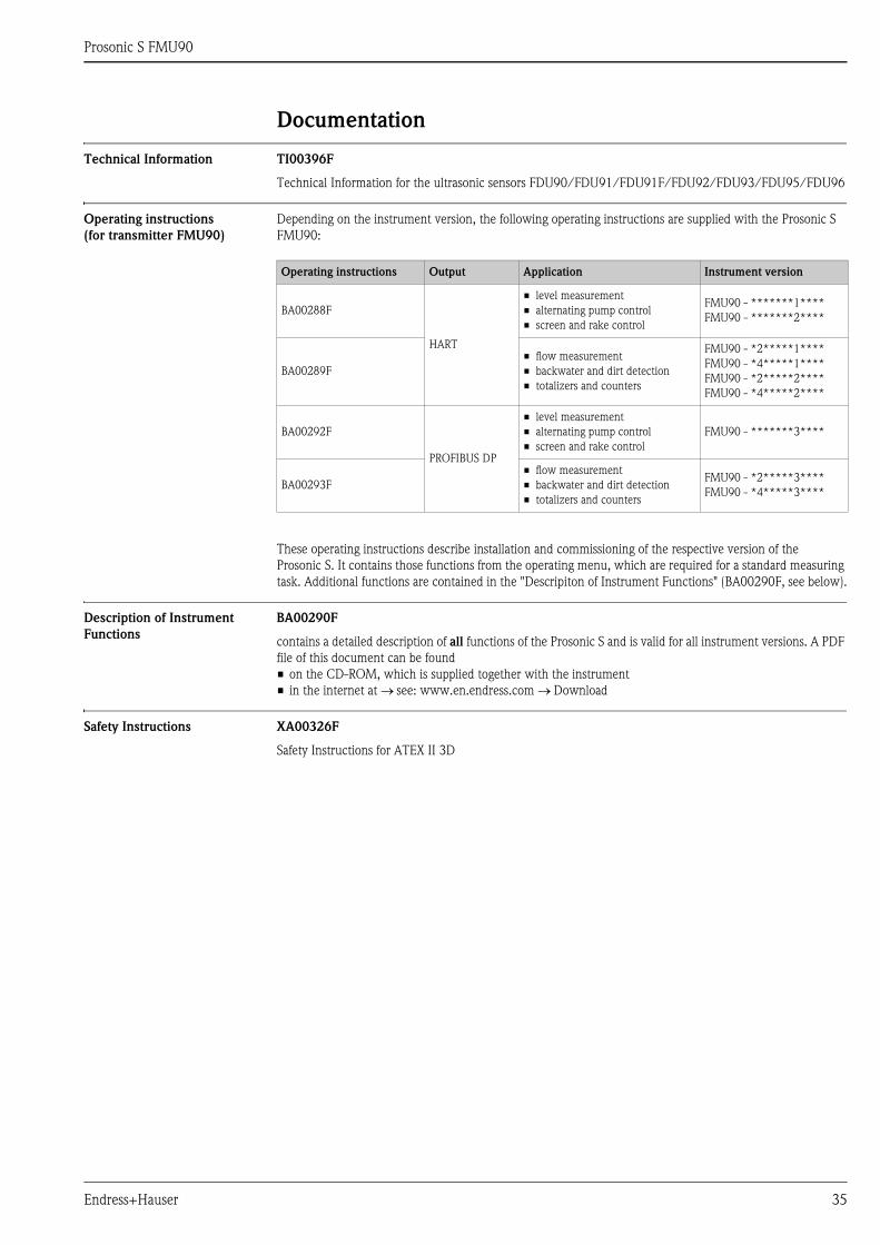
Prosonic S FMU90
Endress+Hauser 35
Documentation
Technical Information TI00396F
Technical Information for the ultrasonic sensors FDU90/FDU91/FDU91F/FDU92/FDU93/FDU95/FDU96
Operating instructions
(for transmitter FMU90)
Depending on the instrument version, the following operating instructions are supplied with the Prosonic S
FMU90:
These operating instructions describe installation and commissioning of the respective version of the
Prosonic S. It contains those functions from the operating menu, which are required for a standard measuring
task. Additional functions are contained in the "Descripiton of Instrument Functions" (BA00290F, see below).
Description of Instrument
Functions
BA00290F
contains a detailed description of all functions of the Prosonic S and is valid for all instrument versions. A PDF
file of this document can be found
• on the CD-ROM, which is supplied together with the instrument
• in the internet at see: www.en.endress.com Download
Safety Instructions XA00326F
Safety Instructions for ATEX II 3D
Operating instructions Output Application Instrument version
BA00288F
HART
• level measurement
• alternating pump control
• screen and rake control
FMU90 - *******1****
FMU90 - *******2****
BA00289F
• flow measurement
• backwater and dirt detection
• totalizers and counters
FMU90 - *2*****1****
FMU90 - *4*****1****
FMU90 - *2*****2****
FMU90 - *4*****2****
BA00292F
PROFIBUS DP
• level measurement
• alternating pump control
• screen and rake control
FMU90 - *******3****
BA00293F
• flow measurement
• backwater and dirt detection
• totalizers and counters
FMU90 - *2*****3****
FMU90 - *4*****3****

Instruments International
Endress+HauserInstruments International AGKaegenstrasse 24153 ReinachSwitzerland
Tel.+41 61 715 81 00Fax+41 61 715 25 [email protected]
TI00397F/00/EN/14.12
71164405
FM+SGML 9.071164405
TOWN OF SMITHFIELD SEWER AUTHORITY
WASTEWATER TREATMENT FACILITY SODIUM HYPOCHLORITE STORAGE TANK
MANDATORY PRE-PROPOSAL CONFERENCE
Page 1 of 2
Identificatio ns
10:00 A.M. April 4, 2018
Owner: Town of Smithfield 64 Farnum Pike Smithfield, Rhode Island 02917 Telephone: (401) 233-1041 Contact: Kevin Cleary, PE, LSIT, Town Engineer
Email: [email protected]
Objectives:
1. The purpose of the Pre-Bid Conference is to answer questions from potential bidders relating to the advertised request for proposals and any information the Town of Smithfield currently has on file for this project.
It is extremely important to note that proposals must be based solely on information contained in the RFP, including any addenda. Nothing stated in this meeting modifies the RFP, unless it is followed up in the context of an Addendum.
2. There have b e e n 3 addendas issued to date for this service request. Any addenda
must be acknowledged in the Bid Submission. Oral statements may not be relied upon and will not be binding or legally effective. Any questions relative to the project, plans or specifications shall be submitted in writing, via letter or email, to the Town Engineer at [email protected]
3. The location of this project is at the Town of Smithfield Wastewater Treatment Facility,
20 Esmond Mill Drive, Smithfield, RI. The services requested are summarized in the RFP.
4. The project is funded by the Town of Smithfield Sewer Authority.
5. Bids must include: - As defined in Request for Proposal and Attachment A, Fee Proposal.

TOWN OF SMITHFIELD SEWER AUTHORITY
WASTEWATER TREATMENT FACILITY SODIUM HYPOCHLORITE STORAGE TANK
MANDATORY PRE-PROPOSAL CONFERENCE
Page 2 of 2
6. Proposals are due at 10:00 A.M., April 13, 2018 at the Smithfield Town Hall, 64 Farnum Pike, Smithfield, RI 02917 in the Office of the Finance Director and will be opened shortly thereafter.
7. The service contract, if awarded, will be awarded to the most qualified respondent within
90 days of the bid opening.
8. Proposers wishing to institute any additional site visits or existing equipment exploration should contact the Town of Smithfield, Kevin Cleary, PE, LSIT.
9. The Town Engineer and Sewer Authority will take into consideration any and all
equipment used to furnish and install said tank at the prescribed location, such as fittings, hardware, couplers, joints, piping and the materials by which are supplied. It is important the prospective bidder use ASTM certified materials that are capable to withstanding the oxidizing properties of the material being stored. The expected useful life of the requested service is expected to be 25-years or more, including all fittings, piping, flanges, couplings, input connections, etc. required on the project to complete the successful installation.
10. Prospective respondents are required to familiarize themselves with the entire project.
11. All proposed staging areas must be coordinated with the Town, but should generally be
limited to the Wastewater Treatment Facility property.
12. The contractor awarded the project will be required to file and obtain any and all necessary building permits with the Smithfield Building Official. Permits are identified by not limited to mechanical, electrical and general building permits, as may be applicable.
13. Project Request for Proposals can be downloaded (no hard copies available):
http://smithfieldri.com/bids/
14. The last date/time to submit questions is April 6, 2018 at 4:30 pm.
15. This is a Mandatory Pre-Bid Conference. Interested Contractors shall sign the attendance sheet. This attendance sheet will be attached to an issued addenda.
16. Q&A