Embed Size (px)
Citation preview
Addendum 1
To Contract Documents for
Payson Smith Hall - 305 96 Falmouth Street
Portland, ME 04103
Prepared by:
49 Dartmouth Street
Portland, Maine 04101
207-775-1059
www.pdtarchs.com
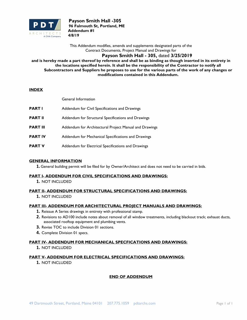
Payson Smith Hall -305 96 Falmouth St, Portland, ME
Addendum #1
4/8/19
49 Dartmouth Street, Portland, Maine 04101 207.775.1059 pdtarchs.com Page 1 of 1
This Addendum modifies, amends and supplements designated parts of the
Contract Documents, Project Manual and Drawings for
Payson Smith Hall - 305, dated 3/25/2019 and is hereby made a part thereof by reference and shall be as binding as though inserted in its entirety in
the locations specified herein. It shall be the responsibility of the Contractor to notify all
Subcontractors and Suppliers he proposes to use for the various parts of the work of any changes or
modifications contained in this Addendum.
INDEX
General Information
PART l Addendum for Civil Specifications and Drawings
PART ll Addendum for Structural Specifications and Drawings
PART lll Addendum for Architectural Project Manual and Drawings
PART lV Addendum for Mechanical Specifications and Drawings
PART V Addendum for Electrical Specifications and Drawings
GENERAL INFORMATION
1. General building permit will be filed for by Owner/Architect and does not need to be carried in bids.
PART I- ADDENDUM FOR CIVIL SPECIFICATIONS AND DRAWINGS:
1. NOT INCLUDED
PART II- ADDENDUM FOR STRUCTURAL SPECIFICATIONS AND DRAWINGS:
1. NOT INCLUDED
PART III- ADDENDUM FOR ARCHITECTURAL PROJECT MANUALS AND DRAWINGS:
1. Reissue A Series drawings in entirety with professional stamp.
2. Revisions to AD100 include notes about removal of all window treatments, including blackout track; exhaust ducts,
associated rooftop equipment and plumbing vents.
3. Revise TOC to include Division 01 sections.
4. Complete Division 01 specs.
PART IV- ADDENDUM FOR MECHANICAL SPECFICATIONS AND DRAWINGS:
1. NOT INCLUDED
PART V- ADDENDUM FOR ELECTRICAL SPECIFICATIONS AND DRAWINGS:
1. NOT INCLUDED
END OF ADDENDUM
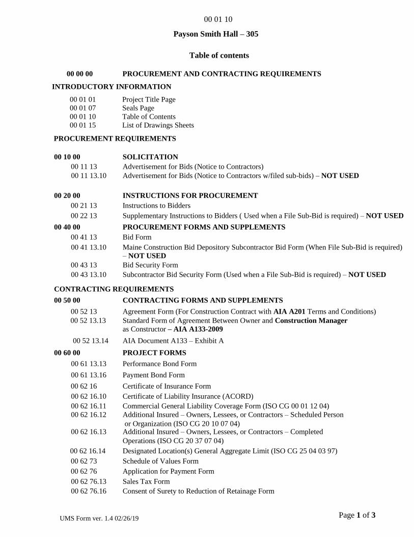
00 01 10
Page 1 of 3 UMS Form ver. 1.4 02/26/19
Payson Smith Hall – 305
Table of contents
00 00 00 PROCUREMENT AND CONTRACTING REQUIREMENTS
INTRODUCTORY INFORMATION
00 01 01 Project Title Page
00 01 07 Seals Page
00 01 10 Table of Contents
00 01 15 List of Drawings Sheets
PROCUREMENT REQUIREMENTS
00 10 00 SOLICITATION
00 11 13 Advertisement for Bids (Notice to Contractors)
00 11 13.10 Advertisement for Bids (Notice to Contractors w/filed sub-bids) – NOT USED
00 20 00 INSTRUCTIONS FOR PROCUREMENT
00 21 13 Instructions to Bidders
00 22 13 Supplementary Instructions to Bidders ( Used when a File Sub-Bid is required) – NOT USED
00 40 00 PROCUREMENT FORMS AND SUPPLEMENTS
00 41 13 Bid Form
00 41 13.10 Maine Construction Bid Depository Subcontractor Bid Form (When File Sub-Bid is required)
– NOT USED
00 43 13 Bid Security Form
00 43 13.10 Subcontractor Bid Security Form (Used when a File Sub-Bid is required) – NOT USED
CONTRACTING REQUIREMENTS
00 50 00 CONTRACTING FORMS AND SUPPLEMENTS
00 52 13 Agreement Form (For Construction Contract with AIA A201 Terms and Conditions)
00 52 13.13 Standard Form of Agreement Between Owner and Construction Manager
as Constructor – AIA A133-2009
00 52 13.14 AIA Document A133 – Exhibit A
00 60 00 PROJECT FORMS
00 61 13.13 Performance Bond Form
00 61 13.16 Payment Bond Form
00 62 16 Certificate of Insurance Form
00 62 16.10 Certificate of Liability Insurance (ACORD)
00 62 16.11 Commercial General Liability Coverage Form (ISO CG 00 01 12 04)
00 62 16.12 Additional Insured – Owners, Lessees, or Contractors – Scheduled Person
00 62 16.13
or Organization (ISO CG 20 10 07 04) Additional Insured – Owners, Lessees, or Contractors – Completed
Operations (ISO CG 20 37 07 04)
00 62 16.14 Designated Location(s) General Aggregate Limit (ISO CG 25 04 03 97)
00 62 73 Schedule of Values Form
00 62 76 Application for Payment Form
00 62 76.13 Sales Tax Form
00 62 76.16 Consent of Surety to Reduction of Retainage Form
00 01 10
Page 2 of 3 UMS Form ver. 1.4 02/26/19
00 62 79 Stored Material Form
00 63 13 Request for Information
00 63 33 Supplemental Instruction Form
00 63 46 Construction Change Directive Form
00 63 57 Change Order Request Form
00 63 63 Change Order Form
00 65 16 Certificate of Substantial Completion Form
00 65 19 Certificate of Completion Form (Final)
00 65 19.13 Affidavit of Payment of Debts and Claims Form
00 65 19.16 Affidavit of Release of Liens Form
00 65 19.17 Waiver of Lien
00 65 19.19 Consent of Surety to Final Payment Form
00 70 00 CONDITIONS OF THE CONTRACT
00 72 00 General Conditions of the Contract for Construction - AIA A201-2017
00 73 00.03 University of Maine System Supplementary Conditions to AIA A133 – 2009
00 73 00.11 Schedule of Liquidated Damages
00 73 00.21 Federally Funded Contract Supplementary Conditions
00 73 00.22 American Recovery and Reinvestment Act Funded Contract Supplementary
Conditions– NOT USED
00 73 00.61 Asbestos Work Supplementary Conditions
00 73 16 Insurance Requirements – AIA A101 Exhibit A Insurance and Bonds - 2017
00 73 46 Wage Determination Schedule 00 73 46.10 Wage Determination Schedule - Davis Bacon ( for Federally Funded Contract)
FACILITY CONSTRUCTION SUBGROUP– NOT USED
DIVISION 01 GENERAL REQUIREMENTS
01 10 00 Summary
01 25 00 Substitution Procedures
01 26 00 Contract Modification Procedures
01 29 00 Payment Procedures
01 31 00 Project Management and Coordination
01 32 00 Construction Progress Documentation
01 33 00 Submittal Procedures
01 42 00 References
01 50 00 Temporary Facilities and Controls
01 60 00 Product Requirements
01 73 00 Execution
01 74 19 Construction Waste Management and Disposal
01 77 00 Closeout Procedures
01 78 39 Project Record Documents
00 01 10
Page 3 of 3 UMS Form ver. 1.4 02/26/19
Division 02 Existing Conditions
Division 03 Concrete
Division 04 Masonry
Division 05 Metals
Division 06 Wood, Plastics & Composites
Division 07 Thermal & Moisture Protection
Division 08 Openings
Division 09 Finishes
Division 10 Specialties
Division 11 thru Division 14 - Not Used
Facility Services Subgroup – NOT USED
Division 21 Fire Suppression
Division 22 Plumbing
Division 23 Heating, Ventilating, and Air Conditioning
Division 24 Not Used
Division 25 Integrated Automation – Not Used
Division 26 Electrical
Division 27 Communications
Division 28 Electronic Safety and Security
00 01 10
Page 4 of 3 UMS Form ver. 1.4 02/26/19
Division 29 Not Used
Site and Infrastructure Subgroup– NOT USED
Division 30 Not Used
Division 31 Earthwork
Division 32 Exterior Improvements
Division 33 Utilities
Division 34 Transportation
Division 35 Waterway and Marine Construction
Division 36 thru 39 – Not Used
Process Equipment Subgroup– NOT USED
Division 40 thru 49 - Not Used
PAYSON SMITH HALL - 305
SUMMARY 01 10 00 - 1
SECTION 01 10 00 - SUMMARY
PART 1 - GENERAL
1.1 RELATED DOCUMENTS
A. Drawings and general provisions of the Contract, including General and Supplementary
Conditions and other Division 01 Specification Sections, apply to this Section.
1.2 SUMMARY
A. Section Includes:
1. Project information.
2. Work covered by Contract Documents.
3. Access to site.
4. Coordination with occupants.
5. Work restrictions.
6. Specification and drawing conventions.
B. Related Requirements:
1. Section 015000 "Temporary Facilities and Controls" for limitations and procedures
governing temporary use of Owner's facilities.
1.3 PROJECT INFORMATION
A. Project Identification: .
1. Project Location: 96 Falmouth St, Portland, ME.
B. Owner: University of Southern Maine.
C. Architect Identification: The Contract Documents were prepared for Project by PDT
Architects, 49 Dartmouth Street, Portland, Maine 04101. Telephone 207-775-1059.
1.4 WORK COVERED BY CONTRACT DOCUMENTS
A. The Work of Project is defined by the Contract Documents and consists of the following:
1. The Work involves the renovation of room 305 on the 3rd floor of Payson Smith Hall.
The project involves removal of finishes, and existing mechanical and electrical
components. New mechanical and electrical systems, roof patching, floor patch, carpet,
paint, ceilings, lighting, white boards, acoustic wall panels, masonry, doors, frames ,
hardware, and window treatments.
PAYSON SMITH HALL - 305
SUMMARY 01 10 00 - 2
1.5 TYPE OF CONTRACT
A. Project will be constructed under a single prime contract.
1.6 ACCESS TO SITE
A. General: Contractor shall have limited use of Project site for construction operations as indicated
on Drawings by the Contract limits and as indicated by requirements of this Section.
B. Use of Site: Limit use of Project site to areas within the Contract limits indicated. Do not disturb
portions of Project site beyond areas in which the Work is indicated.
1. Driveways, Walkways and Entrances: Keep driveways and entrances serving premises
clear and available to Owner, Owner's employees, and emergency vehicles at all times.
Do not use these areas for parking or storage of materials.
a. Schedule deliveries to minimize use of driveways and entrances by construction
operations.
b. Schedule deliveries to minimize space and time requirements for storage of
materials and equipment on-site.
C. Condition of Existing Building: Maintain portions of existing building affected by construction
operations in a weathertight condition throughout construction period. Repair damage caused by
construction operations.
1.7 COORDINATION WITH OCCUPANTS
A. Full Owner Occupancy: Owner will occupy site and existing buildings during entire
construction period. Cooperate with Owner during construction operations to minimize conflicts
and facilitate Owner usage. Perform the Work so as not to interfere with Owner's day-to-day
operations. Maintain existing exits unless otherwise indicated.
1. Maintain access to existing walkways, corridors, and other adjacent occupied or used
facilities. Do not close or obstruct walkways, corridors, or other occupied or used facilities
without written permission from Owner and approval of authorities having jurisdiction.
2. Notify Owner not less than 72 hours in advance of activities that will affect Owner's
operations.
1.8 WORK RESTRICTIONS
A. Work Restrictions, General: Comply with restrictions on construction operations.
1. Comply with limitations on use of public streets and with other requirements of
authorities having jurisdiction.
B. On-Site Work Hours: Work shall be generally performed during normal business working
hours of 7:00 a.m. to 5:00 p.m., Monday through Friday, except otherwise indicated.
PAYSON SMITH HALL - 305
SUMMARY 01 10 00 - 3
1. Weekend Hours: As approved by Architect and Owner.
2. Early Morning Hours: As approved by Architect and Owner.
3. Hours for Utility Shutdowns: As approved by Architect and Owner.
4. Provide 24 hour notice to Architect when performing work other than normal working
hours.
C. Noise, Vibration, and Odors: Coordinate operations that may result in high levels of noise and
vibration, odors, or other disruption to Owner occupancy with Owner.
1. Notify Architect not less than two days in advance of proposed disruptive operations.
2. Obtain Architect's written permission before proceeding with disruptive operations.
D. Smoking is prohibited in and on the grounds of the University.
E. Drugs, Alcohol, Substance Abuses, and Firearms: It is strictly prohibited to posses, use, conceal,
transport, traffic any drugs, alcohol, controlled substances, or firearms on the premises of the
University. Any violations shall be grounds for dismissal and may be cause for termination of
any contracts or portions thereof.
F. Fraternization: Personnel associated with the Construction project shall not associate in any
way with the students, faculty, or staff at the University. The General Contractor shall limit
access of employees to the project site and to the approved access routes. In addition to
fraternization, the use of vulgar language or obscene gestures shall be grounds for immediate
dismissal from this project.
1.9 SPECIFICATION AND DRAWING CONVENTIONS
A. Specification Format: The Specifications are organized into Divisions and Sections using the
33-division format and CSI's "2004 MasterFormat" numbering system.
1. Section Identification: The Specifications use Section numbers and titles to help cross-
referencing in the Contract Documents. Sections in the Project Manual are in numeric
sequence; however, the sequence is incomplete because all available Section numbers are
not used. Consult the table of contents at the beginning of the Project Manual to
determine numbers and names of Sections in the Contract Documents.
2. Division 01 General Requirements: Requirements of Sections in Division 01 apply to the
Work of all Sections in the Specifications.
B. Specification Content: The Specifications use certain conventions for the style of language and
the intended meaning of certain terms, words, and phrases when used in particular situations.
These conventions are as follows:
1. Imperative mood and streamlined language are generally used in the Specifications. The
words "shall," "shall be," or "shall comply with," depending on the context, are implied
where a colon (:) is used within a sentence or phrase.
2. Specification requirements are to be performed by Contractor unless specifically stated
otherwise.
PAYSON SMITH HALL - 305
SUMMARY 01 10 00 - 4
C. Drawing Coordination: Requirements for materials and products identified on Drawings are
described in detail in the Specifications. One or more of the following are used on Drawings to
identify materials and products:
1. Terminology: Materials and products are identified by the typical generic terms used in
the individual Specifications Sections.
2. Abbreviations: Materials and products are identified by abbreviations published as part of
the U.S. National CAD Standard and scheduled on Drawings.
3. Keynoting: Materials and products are identified by reference keynotes referencing
Specification Section numbers found in this Project Manual.
PART 2 - PRODUCTS (Not Used)
PART 3 - EXECUTION (Not Used)
END OF SECTION 01 10 00
PAYSON SMITH HALL - 305
SUBSTITUTION PROCEDURES 01 25 00 - 1
SECTION 01 25 00 - SUBSTITUTION PROCEDURES
PART 1 - GENERAL
1.1 RELATED DOCUMENTS
A. Drawings and general provisions of the Contract, including General and Supplementary
Conditions and other Division 01 Specification Sections, apply to this Section.
1.2 SUMMARY
A. Section includes administrative and procedural requirements for substitutions.
B. Related Requirements:
1. Section 012300 "Alternates" for products selected under an alternate.
2. Section 016000 "Product Requirements" for requirements for submitting comparable
product submittals for products by listed manufacturers.
1.3 DEFINITIONS
A. Substitutions: Changes in products, materials, equipment, and methods of construction from
those required by the Contract Documents and proposed by Contractor.
1. Substitutions for Cause: Changes proposed by Contractor that are required due to changed
Project conditions, such as unavailability of product, regulatory changes, or
unavailability of required warranty terms.
2. Substitutions for Convenience: Changes proposed by Contractor or Owner that are not
required in order to meet other Project requirements but may offer advantage to
Contractor or Owner.
1.4 ACTION SUBMITTALS
A. Substitution Requests: Submit electronic copy of each request for consideration. Identify product
or fabrication or installation method to be replaced. Include Specification Section number and
title and Drawing numbers and titles.
1. Documentation: Show compliance with requirements for substitutions and the following,
as applicable:
a. Statement indicating why specified product or fabrication or installation cannot be
provided, if applicable.
b. Coordination information, including a list of changes or revisions needed to other
parts of the Work and to construction performed by Owner and separate
contractors, that will be necessary to accommodate proposed substitution.
PAYSON SMITH HALL - 305
SUBSTITUTION PROCEDURES 01 25 00 - 2
c. Detailed comparison of significant qualities of proposed substitution with those of
the Work specified. Include annotated copy of applicable Specification Section.
Significant qualities may include attributes such as performance, weight, size,
durability, visual effect, sustainable design characteristics, warranties, and specific
features and requirements indicated. Indicate deviations, if any, from the Work
specified.
d. Product Data, including drawings and descriptions of products and fabrication and
installation procedures. e. Samples, where applicable or requested.
f. Certificates and qualification data, where applicable or requested.
g. List of similar installations for completed projects with project names and
addresses and names and addresses of architects and owners.
h. Material test reports from a qualified testing agency indicating and interpreting test
results for compliance with requirements indicated.
i. Research reports evidencing compliance with building code in effect for Project,
from ICC-ES.
j. Detailed comparison of Contractor's construction schedule using proposed
substitution with products specified for the Work, including effect on the overall
Contract Time. If specified product or method of construction cannot be provided
within the Contract Time, include letter from manufacturer, on manufacturer's
letterhead, stating date of receipt of purchase order, lack of availability, or delays
in delivery. k. Cost information, including a proposal of change, if any, in the Contract Sum.
l. Contractor's certification that proposed substitution complies with requirements in
the Contract Documents except as indicated in substitution request, is compatible
with related materials, and is appropriate for applications indicated.
m. Contractor's waiver of rights to additional payment or time that may subsequently
become necessary because of failure of proposed substitution to produce indicated
results.
2. Architect's Action: If necessary, Architect will request additional information or
documentation for evaluation within three days of receipt of a request for substitution.
Architect will notify Contractor of acceptance or rejection of proposed substitution by
addendum.
a. Use product specified if Architect cannot make a decision on use of a proposed
substitution within time allocated or notification is not made by addendum.
1.5 QUALITY ASSURANCE
A. Compatibility of Substitutions: Investigate and document compatibility of proposed substitution
with related products and materials. Engage a qualified testing agency to perform compatibility
tests recommended by manufacturers.
1.6 PROCEDURES
A. Coordination: Revise or adjust affected work as necessary to integrate work of the approved
substitutions.
PAYSON SMITH HALL - 305
SUBSTITUTION PROCEDURES 01 25 00 - 3
PART 2 - PRODUCTS
2.1 SUBSTITUTIONS
A. Substitutions: Architect will consider requests for substitution if received within the time
indicated in Instructions to Bidders. Requests received after that time may be considered or
rejected at discretion of Architect.
1. Conditions: Architect will consider Contractor's request for substitution when the
following conditions are satisfied. If the following conditions are not satisfied, Architect
will return requests without action, except to record noncompliance with these
requirements:
a. Requested substitution offers Owner a substantial advantage in cost, time, energy
conservation, or other considerations, after deducting additional responsibilities
Owner must assume. Owner's additional responsibilities may include compensation
to Architect for redesign and evaluation services, increased cost of other
construction by Owner, and similar considerations.
b. Requested substitution does not require extensive revisions to the Contract
Documents.
c. Requested substitution is consistent with the Contract Documents and will produce
indicated results. d. Substitution request is fully documented and properly submitted.
e. Requested substitution will not adversely affect Contractor's construction schedule.
f. Requested substitution has received necessary approvals of authorities having
jurisdiction. g. Requested substitution is compatible with other portions of the Work.
h. Requested substitution has been coordinated with other portions of the Work.
i. Requested substitution provides specified warranty.
j. If requested substitution involves more than one contractor, requested substitution
has been coordinated with other portions of the Work, is uniform and consistent, is
compatible with other products, and is acceptable to all contractors involved.
PART 3 - EXECUTION (Not Used)
END OF SECTION 01 25 00
PAYSON SMITH HALL - 305
CONTRACT MODIFICATION PROCEDURES 01 26 00 - 1
SECTION 01 26 00 - CONTRACT MODIFICATION PROCEDURES
PART 1 - GENERAL
1.1 RELATED DOCUMENTS
A. Drawings and general provisions of the Contract, including General and Supplementary
Conditions and other Division 01 Specification Sections, apply to this Section.
1.2 SUMMARY
A. Section includes administrative and procedural requirements for handling and processing
Contract modifications.
B. Related Requirements:
1. Section 012500 "Substitution Procedures" for administrative procedures for handling
requests for substitutions made after the Contract award.
1.3 MINOR CHANGES IN THE WORK
A. Architect will issue supplemental instructions authorizing minor changes in the Work, not
involving adjustment to the Contract Sum or the Contract Time, on AIA Document G710,
"Architect's Supplemental Instructions"
1.4 PROPOSAL REQUESTS
A. Owner-Initiated Proposal Requests: Architect will issue a detailed description of proposed
changes in the Work that may require adjustment to the Contract Sum or the Contract Time. If
necessary, the description will include supplemental or revised Drawings and Specifications.
1. Work Change Proposal Requests issued by Architect are not instructions either to stop
work in progress or to execute the proposed change.
2. Within 20 days, when not otherwise specified, after receipt of Proposal Request, submit a
quotation estimating cost adjustments to the Contract Sum and the Contract Time
necessary to execute the change.
a. Include a list of quantities of products required or eliminated and unit costs, with
total amount of purchases and credits to be made. If requested, furnish survey data
to substantiate quantities.
b. Indicate applicable bonds, insurance, taxes, delivery charges, equipment rental, and
amounts of trade discounts.
c. Include costs of labor and supervision directly attributable to the change.
d. Include quotes on supplier’s and subcontractor’s letterhead for the requested
change.
PAYSON SMITH HALL - 305
CONTRACT MODIFICATION PROCEDURES 01 26 00 - 2
e. Include an updated Contractor's construction schedule that indicates the effect of
the change, including, but not limited to, changes in activity duration, start and
finish times, and activity relationship. Use available total float before requesting an
extension of the Contract Time.
B. Contractor-Initiated Proposals: If latent or changed conditions require modifications to the
Contract, Contractor may initiate a claim by submitting a request for a change to Architect.
1. Include a statement outlining reasons for the change and the effect of the change on the
Work. Provide a complete description of the proposed change. Indicate the effect of the
proposed change on the Contract Sum and the Contract Time.
2. Include a list of quantities of products required or eliminated and unit costs, with total
amount of purchases and credits to be made. If requested, furnish survey data to
substantiate quantities.
3. Indicate applicable bonds, insurance, taxes, delivery charges, equipment rental, and
amounts of trade discounts.
4. Include costs of labor and supervision directly attributable to the change.
5. Include an updated Contractor's construction schedule that indicates the effect of the
change, including, but not limited to, changes in activity duration, start and finish times,
and activity relationship. Use available total float before requesting an extension of the
Contract Time.
6. Comply with requirements in Section 012500 "Substitution Procedures" if the proposed
change requires substitution of one product or system for product or system specified.
7. Proposal Request Form: Use form acceptable to Architect.
C. Proposal Request Form: Use AIA Document G709 for Proposal Requests.
1.5 CHANGE ORDER PROCEDURES
A. On Owner's approval of a Work Changes Proposal Request, Architect will issue a Change Order
for signatures of Owner and Contractor on AIA Document G701.
1.6 CONSTRUCTION CHANGE DIRECTIVE
A. Construction Change Directive: Architect may issue a Construction Change Directive on AIA
Document G714. Construction Change Directive instructs Contractor to proceed with a change
in the Work, for subsequent inclusion in a Change Order.
1. Construction Change Directive contains a complete description of change in the Work. It
also designates method to be followed to determine change in the Contract Sum or the
Contract Time.
B. Documentation: Maintain detailed records on a time and material basis of work required by the
Construction Change Directive.
1. After completion of change, submit an itemized account and supporting data necessary to
substantiate cost and time adjustments to the Contract.
PAYSON SMITH HALL - 305
CONTRACT MODIFICATION PROCEDURES 01 26 00 - 3
PART 2 - PRODUCTS (Not Used)
PART 3 - EXECUTION (Not Used)
END OF SECTION 01 26 00
PAYSON SMITH HALL - 305
PAYMENT PROCEDURES 01 29 00 - 1
SECTION 01 29 00 - PAYMENT PROCEDURES
PART 1 - GENERAL
1.1 RELATED DOCUMENTS
A. Drawings and general provisions of the Contract, including General and Supplementary
Conditions and other Division 01 Specification Sections, apply to this Section.
1.2 SUMMARY
A. Section includes administrative and procedural requirements necessary to prepare and process
Applications for Payment.
B. Related Requirements:
1. Section 01 26 00 "Contract Modification Procedures" for administrative procedures for
handling changes to the Contract.
2. Section 01 32 00 "Construction Progress Documentation" for administrative requirements
governing the preparation and submittal of the Contractor's construction schedule.
1.3 DEFINITIONS
A. Schedule of Values: A statement furnished by Contractor allocating portions of the Contract
Sum to various portions of the Work and used as the basis for reviewing Contractor's
Applications for Payment.
1.4 SCHEDULE OF VALUES
A. Coordination: Coordinate preparation of the schedule of values with preparation of Contractor's
construction schedule.
1. Coordinate line items in the schedule of values with other required administrative forms
and schedules, including the following:
a. Application for Payment forms with continuation sheets.
b. Submittal schedule.
c. Items required to be indicated as separate activities in Contractor's construction
schedule.
2. Submit the schedule of values to Architect at earliest possible date, but no later than
seven days before the date scheduled for submittal of initial Applications for Payment.
3. Subschedules for Separate Elements of Work: Where the Contractor's construction
schedule defines separate elements of the Work, provide subschedules showing values
coordinated with each element.
PAYSON SMITH HALL - 305
PAYMENT PROCEDURES 01 29 00 - 2
B. Format and Content: Use Project Manual table of contents as a guide to establish line items for
the schedule of values. Provide at least one line item for each Specification Section.
1. Identification: Include the following Project identification on the schedule of values:
a. Project name and location.
b. Name of Architect.
c. Architect's project number.
d. Contractor's name and address.
e. Date of submittal.
2. Arrange schedule of values consistent with format of AIA Document G703.
3. Arrange the schedule of values in tabular form with separate columns to indicate the
following for each item listed:
a. Related Specification Section or Division. b. Description of the Work.
c. Name of subcontractor.
d. Name of manufacturer or fabricator.
e. Name of supplier.
f. Change Orders (numbers) that affect value.
g. Dollar value of the following, as a percentage of the Contract Sum to nearest one-
hundredth percent, adjusted to total 100 percent.
1) Labor.
2) Materials.
3) Equipment.
4. Provide a breakdown of the Contract Sum in enough detail to facilitate continued
evaluation of Applications for Payment and progress reports. Coordinate with Project
Manual table of contents. Provide multiple line items for principal subcontract amounts
in excess of five percent of the Contract Sum.
a. Include separate line items under Contractor and principal subcontracts for Project
closeout requirements in an amount totaling five percent of the Contract Sum and
subcontract amount.
5. Round amounts to nearest whole dollar; total shall equal the Contract Sum.
6. Provide a separate line item in the schedule of values for each part of the Work where
Applications for Payment may include materials or equipment purchased or fabricated
and stored, but not yet installed.
a. Differentiate between items stored on-site and items stored off-site. If required,
include evidence of insurance.
7. Provide separate line items in the schedule of values for initial cost of materials, for each
subsequent stage of completion, and for total installed value of that part of the Work.
8. Each item in the schedule of values and Applications for Payment shall be complete.
Include total cost and proportionate share of general overhead and profit for each item.
PAYSON SMITH HALL - 305
PAYMENT PROCEDURES 01 29 00 - 3
a. Temporary facilities and other major cost items that are not direct cost of actual
work-in-place may be shown either as separate line items in the schedule of values
or distributed as general overhead expense, at Contractor's option.
9. Schedule Updating: Update and resubmit the schedule of values before the next
Applications for Payment when Change Orders or Construction Change Directives result
in a change in the Contract Sum.
C. Draw-Down Schedule: The Contractor shall furnish to the Architect, at the beginning of the
project, an expected monthly requisition estimate for the Owner’s use in planning funding.
1.5 APPLICATIONS FOR PAYMENT
A. Each Application for Payment following the initial Application for Payment shall be consistent
with previous applications and payments as certified by Architect and paid for by Owner.
1. Initial Application for Payment, Application for Payment at time of Substantial
Completion, and final Application for Payment involve additional requirements.
B. Payment Application Times: The date for each progress payment is indicated in the Agreement
between Owner and Contractor. The period of construction work covered by each Application
for Payment is the period indicated in the Agreement.
1. Submit draft copy of Application for Payment seven days prior to due date for review by
Architect.
C. Application for Payment Forms: Use AIA Document G702 and AIA Document G703 as form
for Applications for Payment.
D. Application Preparation: Complete every entry on form. Notarize and execute by a person
authorized to sign legal documents on behalf of Contractor. Architect will return incomplete
applications without action.
1. Entries shall match data on the schedule of values and Contractor's construction schedule.
Use updated schedules if revisions were made.
2. Include amounts for work completed following previous Application for Payment,
whether or not payment has been received. Include only amounts for work completed at
time of Application for Payment.
3. Include amounts of Change Orders and Construction Change Directives issued before last
day of construction period covered by application.
E. Stored Materials: Include in Application for Payment amounts applied for materials or
equipment purchased or fabricated and stored, but not yet installed. Differentiate between items
stored on-site and items stored off-site.
1. Provide certificate of insurance, evidence of transfer of title to Owner, and consent of
surety to payment, for stored materials.
2. Provide supporting documentation that verifies amount requested, such as paid invoices.
Match amount requested with amounts indicated on documentation; do not include
overhead and profit on stored materials.
PAYSON SMITH HALL - 305
PAYMENT PROCEDURES 01 29 00 - 4
3. Provide summary documentation for stored materials indicating the following:
a. Value of materials previously stored and remaining stored as of date of previous
Applications for Payment.
b. Value of previously stored materials put in place after date of previous Application
for Payment and on or before date of current Application for Payment.
c. Value of materials stored since date of previous Application for Payment and
remaining stored as of date of current Application for Payment.
F. Transmittal: Submit three signed and notarized original copies of each Application for Payment
to Architect by a method ensuring receipt within 24 hours. One copy shall include waivers of
lien and similar attachments if required.
1. Transmit each copy with a transmittal form listing attachments and recording appropriate
information about application.
G. Waivers of Mechanic's Lien: With each Application for Payment, submit waivers of mechanic's
liens from subcontractors, sub-subcontractors, and suppliers for construction period covered by
the previous application.
1. Submit partial waivers on each item for amount requested in previous application, after
deduction for retainage, on each item.
2. When an application shows completion of an item, submit conditional final or full
waivers.
3. The list of subcontractors, principal suppliers and fabricators shall be used to designate
which entities involved in the Work must submit waivers. The list shall be approved by
the Owner.
4. Submit final Application for Payment with or preceded by conditional final waivers from
every entity involved with performance of the Work covered by the application who is
lawfully entitled to a lien. 5. Waiver Forms: Submit executed waivers of lien on forms, acceptable to Owner.
H. Record Drawing Updates: With each Application of Payment, record documents shall be
maintained and current for all trades, available for viewing at a central location.
I. Initial Application for Payment: Administrative actions and submittals that must precede or
coincide with submittal of first Application for Payment include the following:
1. List of subcontractors. 2. Schedule of values.
3. Contractor's construction schedule (preliminary if not final).
4. Combined Contractor's construction schedule (preliminary if not final) incorporating
Work of multiple contracts, with indication of acceptance of schedule by each Contractor. 5. Products list (preliminary if not final).
6. Submittal schedule (preliminary if not final).
7. List of Contractor's staff assignments.
8. List of Contractor's principal consultants.
9. Copies of building permits and other required permits.
10. Copies of authorizations and licenses from authorities having jurisdiction for
performance of the Work. 11. Initial progress report.
PAYSON SMITH HALL - 305
PAYMENT PROCEDURES 01 29 00 - 5
12. Report of preconstruction conference.
13. Certificates of insurance and insurance policies.
14. Performance and payment bonds.
J. Progress Applications for Payment: Administrative actions and submittals that must precede or
coincide with submittal of progress Applications for Payment include the following:
1. Contractor's Construction Schedule update.
2. Submittals for Work being requisitioned for are complete and approved.
3. Minutes of previous month’s progress meeting have been distributed.
4. Record drawings and documents are current.
K. Application for Payment at Substantial Completion: After Architect issues the Certificate of
Substantial Completion, submit an Application for Payment showing 100 percent completion
for portion of the Work claimed as substantially complete.
1. Include documentation supporting claim that the Work is substantially complete and a
statement showing an accounting of changes to the Contract Sum.
2. This application shall reflect Certificate(s) of Substantial Completion issued previously
for Owner occupancy of designated portions of the Work.
L. Final Payment Application: After completing Project closeout requirements, submit final
Application for Payment with releases and supporting documentation not previously submitted
and accepted, including, but not limited, to the following:
1. Evidence of completion of Project closeout requirements.
2. Final submittal of record documents and operation, maintenance data and demonstration
and training.
3. Insurance certificates for products and completed operations where required and proof
that taxes, fees, and similar obligations were paid. 4. Updated final statement, accounting for final changes to the Contract Sum.
5. Waiver Forms: Submit waivers of lien on forms, and executed in a manner, acceptable to
the Owner. 6. AIA Document G706, "Contractor's Affidavit of Payment of Debts and Claims."
7. AIA Document G706A, "Contractor's Affidavit of Release of Liens."
8. AIA Document G707, "Consent of Surety to Final Payment."
9. Evidence that claims have been settled.
10. Final meter readings for utilities, a measured record of stored fuel, and similar data as of
date of Substantial Completion or when Owner took possession of and assumed
responsibility for corresponding elements of the Work.
11. Final liquidated damages settlement statement, if applicable.
PART 2 - PRODUCTS (Not Used)
PART 3 - EXECUTION (Not Used)
END OF SECTION 01 29 00
PAYSON SMITH HALL - 305
PROJECT MANAGEMENT AND COORDINATION 01 31 00 - 1
SECTION 01 31 00 - PROJECT MANAGEMENT AND COORDINATION
PART 1 - GENERAL
1.1 RELATED DOCUMENTS
A. Drawings and general provisions of the Contract, including General and Supplementary
Conditions and other Division 01 Specification Sections, apply to this Section.
1.2 SUMMARY
A. Section includes administrative provisions for coordinating construction operations on Project
including, but not limited to, the following:
1. General coordination procedures. 2. Requests for Information (RFIs).
3. Project meetings.
B. Each contractor shall participate in coordination requirements. Certain areas of responsibility
are assigned to a specific contractor.
1.3 DEFINITIONS
A. RFI: Request from Owner, Architect, or Contractor seeking information required by or
clarifications of the Contract Documents.
1.4 INFORMATIONAL SUBMITTALS
A. Subcontract List: Prepare a written summary identifying individuals or firms proposed for each
portion of the Work, including those who are to furnish products or equipment fabricated to a
special design. Include the following information in tabular form:
1. Name, address, and telephone number of entity performing subcontract or supplying
products.
2. Number and title of related Specification Section(s) covered by subcontract.
3. Drawing number and detail references, as appropriate, covered by subcontract.
B. Key Personnel Names: Within 15 days of starting construction operations, submit a list of key
personnel assignments, including superintendent and other personnel in attendance at Project
site. Identify individuals and their duties and responsibilities; list addresses and telephone
numbers, including home, office, and cellular telephone numbers and e-mail addresses. Provide
names, addresses, and telephone numbers of individuals assigned as alternates in the absence of
individuals assigned to Project.
1. Post copies of list in project meeting room, in temporary field office, and by each
temporary telephone. Keep list current at all times.
PAYSON SMITH HALL - 305
PROJECT MANAGEMENT AND COORDINATION 01 31 00 - 2
1.5 GENERAL COORDINATION PROCEDURES
A. Coordination: Coordinate construction operations included in different Sections of the
Specifications to ensure efficient and orderly installation of each part of the Work. Coordinate
construction operations, included in different Sections that depend on each other for proper
installation, connection, and operation.
1. Schedule construction operations in sequence required to obtain the best results where
installation of one part of the Work depends on installation of other components, before
or after its own installation.
2. Coordinate installation of different components to ensure maximum performance and
accessibility for required maintenance, service, and repair.
3. Make adequate provisions to accommodate items scheduled for later installation.
B. Prepare memoranda for distribution to each party involved, outlining special procedures required
for coordination. Include such items as required notices, reports, and list of attendees at meetings.
1. Prepare similar memoranda for Owner and separate contractors if coordination of their
Work is required.
C. Administrative Procedures: Coordinate scheduling and timing of required administrative
procedures with other construction activities and activities of other contractors to avoid conflicts
and to ensure orderly progress of the Work. Such administrative activities include, but are not
limited to, the following:
1. Preparation of Contractor's construction schedule.
2. Preparation of the schedule of values.
3. Installation and removal of temporary facilities and controls.
4. Delivery and processing of submittals.
5. Progress meetings.
6. Preinstallation conferences.
7. Project closeout activities.
D. Conservation: Coordinate construction activities to ensure that operations are carried out with
consideration given to conservation of energy, water, and materials. Coordinate use of
temporary utilities to minimize waste.
1. Salvage materials and equipment involved in performance of, but not actually
incorporated into, the Work. See other Sections for disposition of salvaged materials that
are designated as Owner's property.
1.6 REQUESTS FOR INFORMATION (RFIs)
A. General: Immediately on discovery of the need for additional information or interpretation of
the Contract Documents, Contractor shall prepare and submit an RFI in the form specified.
1. Architect will return RFIs submitted to Architect by other entities controlled by
Contractor with no response.
PAYSON SMITH HALL - 305
PROJECT MANAGEMENT AND COORDINATION 01 31 00 - 3
2. Coordinate and submit RFIs in a prompt manner so as to avoid delays in Contractor's
work or work of subcontractors.
B. Content of the RFI: Include a detailed, legible description of item needing information or
interpretation and the following:
1. Project name.
2. Project number.
3. Date.
4. Name of Contractor.
5. Name of Architect.
6. RFI number, numbered sequentially.
7. RFI subject.
8. Specification Section number and title and related paragraphs, as appropriate.
9. Drawing number and detail references, as appropriate.
10. Field dimensions and conditions, as appropriate.
11. Contractor's suggested resolution. If Contractor's suggested resolution impacts the
Contract Time or the Contract Sum, Contractor shall state impact in the RFI. 12. Contractor's signature.
13. Attachments: Include sketches, descriptions, measurements, photos, Product Data, Shop
Drawings, coordination drawings, and other information necessary to fully describe items
needing interpretation.
a. Include dimensions, thicknesses, structural grid references, and details of affected
materials, assemblies, and attachments on attached sketches.
C. RFI Forms: Software-generated form with substantially the same content as indicated above,
acceptable to Architect.
1. Attachments shall be electronic files in Adobe Acrobat PDF format.
D. Architect's Action: Architect will review each RFI, determine action required, and respond.
RFIs received by Architect after 1:00 p.m. will be considered as received the following working
day.
1. The following Contractor-generated RFIs will be returned without action:
a. Requests for approval of submittals.
b. Requests for approval of substitutions.
c. Requests for approval of Contractor's means and methods.
d. Requests for coordination information already indicated in the Contract
Documents.
e. Requests for adjustments in the Contract Time or the Contract Sum.
f. Requests for interpretation of Architect's actions on submittals.
g. Incomplete RFIs or inaccurately prepared RFIs.
2. Architect's action may include a request for additional information, in which case
Architect's time for response will date from time of receipt of additional information.
3. Architect's action on RFIs that may result in a change to the Contract Time or the
Contract Sum may be eligible for Contractor to submit Change Proposal according to
Section 012600 "Contract Modification Procedures."
PAYSON SMITH HALL - 305
PROJECT MANAGEMENT AND COORDINATION 01 31 00 - 4
a. If Contractor believes the RFI response warrants change in the Contract Time or
the Contract Sum, notify Architect in writing within 10 days of receipt of the RFI
response.
E. RFI Log: Prepare, maintain, and submit a tabular log of RFIs organized by the RFI number.
Submit log weekly. Software log with not less than the following:
1. Project name.
2. Name and address of Contractor.
3. Name and address of Architect.
4. RFI number including RFIs that were returned without action or withdrawn.
5. RFI description.
6. Date the RFI was submitted.
7. Date Architect's response was received.
F. On receipt of Architect's action, update the RFI log and immediately distribute the RFI response
to affected parties. Review response and notify Architect within seven days if Contractor
disagrees with response.
1. Identification of related Minor Change in the Work, Construction Change Directive, and
Proposal Request, as appropriate.
2. Identification of related Field Order, Work Change Directive, and Proposal Request, as
appropriate.
1.7 PROJECT MEETINGS
A. General: Schedule and conduct meetings and conferences at Project site unless otherwise
indicated.
1. Attendees: Inform participants and others involved, and individuals whose presence is
required, of date and time of each meeting. Notify Owner and Architect of scheduled
meeting dates and times. 2. Agenda: Prepare the meeting agenda. Distribute the agenda to all invited attendees.
3. Minutes: Entity responsible for conducting meeting will record significant discussions
and agreements achieved. Distribute the meeting minutes to everyone concerned,
including Owner and Architect, within three days of the meeting.
B. Preconstruction Conference: Schedule and conduct a preconstruction conference before starting
construction, at a time convenient to Owner and Architect, but no later than 15 days after
execution of the Agreement.
1. Conduct the conference to review responsibilities and personnel assignments.
2. Attendees: Authorized representatives of Owner Architect, and their consultants;
Contractor and its superintendent; major subcontractors; suppliers; and other concerned
parties shall attend the conference. Participants at the conference shall be familiar with
Project and authorized to conclude matters relating to the Work. 3. Agenda: Discuss items of significance that could affect progress, including the following:
a. Tentative construction schedule.
b. Critical work sequencing and long-lead items.
PAYSON SMITH HALL - 305
PROJECT MANAGEMENT AND COORDINATION 01 31 00 - 5
c. Designation of key personnel and their duties.
d. Lines of communications.
e. Procedures for processing field decisions and Change Orders.
f. Procedures for RFIs.
g. Procedures for processing Applications for Payment.
h. Distribution of the Contract Documents.
i. Submittal procedures.
j. Preparation of record documents.
k. Use of the premises and existing building.
l. Work restrictions.
m. Working hours.
n. Owner's occupancy requirements.
o. Responsibility for temporary facilities and controls.
p. Procedures for moisture and mold control.
q. Procedures for disruptions and shutdowns.
r. Construction waste management and recycling.
s. Parking availability.
t. Office, work, and storage areas.
u. Equipment deliveries and priorities.
v. First aid.
w. Security.
x. Progress cleaning.
4. Minutes: Entity responsible for conducting meeting will record and distribute meeting
minutes.
C. Project Closeout Conference: Schedule and conduct a project closeout conference, at a time
convenient to Owner and Architect, but no later than 30 days prior to the scheduled date of
Substantial Completion.
1. Conduct the conference to review requirements and responsibilities related to Project
closeout.
2. Attendees: Authorized representatives of Owner, Architect, and their consultants;
Contractor and its superintendent; major subcontractors; suppliers; and other concerned
parties shall attend the meeting. Participants at the meeting shall be familiar with Project
and authorized to conclude matters relating to the Work.
3. Agenda: Discuss items of significance that could affect or delay Project closeout,
including the following:
a. Preparation of record documents.
b. Procedures required prior to inspection for Substantial Completion and for final
inspection for acceptance.
c. Submittal of written warranties.
d. Requirements for delivery of material samples, attic stock, and spare parts.
e. Preparation of Contractor's punch list.
f. Procedures for processing Applications for Payment at Substantial Completion and
for final payment.
g. Submittal procedures.
h. Owner's partial occupancy requirements.
i. Responsibility for removing temporary facilities and controls.
PAYSON SMITH HALL - 305
PROJECT MANAGEMENT AND COORDINATION 01 31 00 - 6
4. Minutes: Entity conducting meeting will record and distribute meeting minutes.
D. Progress Meetings: Conduct progress meetings at monthly intervals.
1. Coordinate dates of meetings with preparation of payment requests.
2. Attendees: In addition to representatives of Owner and Architect, each contractor,
subcontractor, supplier, and other entity concerned with current progress or involved in
planning, coordination, or performance of future activities shall be represented at these
meetings. All participants at the meeting shall be familiar with Project and authorized to
conclude matters relating to the Work.
3. Agenda: Review and correct or approve minutes of previous progress meeting. Review
other items of significance that could affect progress. Include topics for discussion as
appropriate to status of Project.
a. Contractor's Construction Schedule: Review progress since the last meeting.
Determine whether each activity is on time, ahead of schedule, or behind schedule,
in relation to Contractor's construction schedule. Determine how construction
behind schedule will be expedited; secure commitments from parties involved to
do so. Discuss whether schedule revisions are required to ensure that current and
subsequent activities will be completed within the Contract Time.
1) Review schedule for next period.
b. Application for Payment: Contractor shall bring copy of Application for Payment
to meeting. Review Application for Payment and required attachments, including
record drawing and documents status, waivers of mechanic's liens, list of
completed tests, checklists, commissioning, reports, and similar requirements for
the work are submitted and in compliance with the Contract Documents.
c. Review present and future needs of each entity present, including the following:
1) Interface requirements.
2) Sequence of operations.
3) Status of submittals.
4) Deliveries.
5) Off-site fabrication.
6) Access.
7) Site utilization.
8) Temporary facilities and controls.
9) Progress cleaning.
10) Quality and work standards.
11) Status of correction of deficient items.
12) Field observations.
13) Status of RFIs.
14) Status of proposal requests.
15) Pending changes.
16) Status of Change Orders.
17) Pending claims and disputes.
18) Documentation of information for payment requests.
4. Minutes: Entity responsible for conducting the meeting will record and distribute the
meeting minutes to each party present and to parties requiring information.
PAYSON SMITH HALL - 305
PROJECT MANAGEMENT AND COORDINATION 01 31 00 - 7
a. Schedule Updating: Revise Contractor's construction schedule after each progress
meeting where revisions to the schedule have been made or recognized. Issue
revised schedule concurrently with the report of each meeting.
E. Coordination Meetings: Conduct Project coordination meetings at regular intervals. Project
coordination meetings are in addition to specific meetings held for other purposes, such as
progress meetings and preinstallation conferences.
1. Attendees: In addition to representatives of Owner and Architect, each contractor,
subcontractor, supplier, and other entity concerned with current progress or involved in
planning, coordination, or performance of future activities shall be represented at these
meetings. All participants at the meetings shall be familiar with Project and authorized to
conclude matters relating to the Work.
2. Agenda: Review and correct or approve minutes of the previous coordination meeting.
Review other items of significance that could affect progress. Include topics for
discussion as appropriate to status of Project.
a. Combined Contractor's Construction Schedule: Review progress since the last
coordination meeting. Determine whether each contract is on time, ahead of
schedule, or behind schedule, in relation to combined Contractor's construction
schedule. Determine how construction behind schedule will be expedited; secure
commitments from parties involved to do so. Discuss whether schedule revisions
are required to ensure that current and subsequent activities will be completed
within the Contract Time.
b. Schedule Updating: Revise combined Contractor's construction schedule after each
coordination meeting where revisions to the schedule have been made or
recognized. Issue revised schedule concurrently with report of each meeting.
c. Review present and future needs of each contractor present, including the
following:
1) Interface requirements.
2) Sequence of operations.
3) Status of submittals.
4) Deliveries.
5) Off-site fabrication.
6) Access.
7) Site utilization.
8) Temporary facilities and controls.
9) Work hours.
10) Hazards and risks.
11) Progress cleaning.
12) Quality and work standards.
13) Change Orders.
3. Conduct coordination meetings with the mechanical, plumbing, sprinkler and electrical
trades. Before the trades start work in an area of the building, make field measurements,
review structural clearances and locations of ducts, pipes, conduits, light fixtures,
equipment and other items that affect location and proper fit. Prepare coordination
sketches to maximize utilization of space for efficient installation of different components.
Verify depths and clearances before fabrication of ductwork.
PAYSON SMITH HALL - 305
PROJECT MANAGEMENT AND COORDINATION 01 31 00 - 8
4. Reporting: Record meeting results and distribute copies to everyone in attendance and to
others affected by decisions or actions resulting from each meeting.
PART 2 - PRODUCTS (Not Used)
PART 3 - EXECUTION (Not Used)
END OF SECTION 01 31 00
PAYSON SMITH HALL - 305
CONSTRUCTION PROGRESS DOCUMENTATION 01 32 00 - 1
SECTION 01 32 00 - CONSTRUCTION PROGRESS DOCUMENTATION
PART 1 - GENERAL
1.1 RELATED DOCUMENTS
A. Drawings and general provisions of the Contract, including General and Supplementary
Conditions and other Division 01 Specification Sections, apply to this Section.
1.2 SUMMARY
A. Section includes administrative and procedural requirements for documenting the progress of
construction during performance of the Work, including the following:
1. Startup construction schedule. 2. Contractor's construction schedule.
3. Construction schedule updating reports.
4. Daily construction reports.
5. Material location reports.
6. Site condition reports.
7. Special reports.
B. Related Requirements:
1. Section 01 33 00 "Submittal Procedures" for submitting schedules and reports.
2. Section 01 40 00 "Quality Requirements" for submitting a schedule of tests and
inspections.
1.3 DEFINITIONS
A. Activity: A discrete part of a project that can be identified for planning, scheduling, monitoring,
and controlling the construction project. Activities included in a construction schedule consume
time and resources.
1. Critical Activity: An activity on the critical path that must start and finish on the planned
early start and finish times.
2. Predecessor Activity: An activity that precedes another activity in the network.
3. Successor Activity: An activity that follows another activity in the network.
B. Critical Path: The longest connected chain of interdependent activities through the network
schedule that establishes the minimum overall Project duration and contains no float.
C. Event: The starting or ending point of an activity.
D. Float: The measure of leeway in starting and completing an activity.
PAYSON SMITH HALL - 305
CONSTRUCTION PROGRESS DOCUMENTATION 01 32 00 - 2
1.4 INFORMATIONAL SUBMITTALS
A. Format for Submittals: Submit required submittals in the following format:
1. PDF electronic file.
B. Startup construction schedule.
C. Contractor's Construction Schedule: Initial schedule, of size required to display entire schedule
for entire construction period.
D. Construction Schedule Updating Reports: Submit with Applications for Payment.
E. Daily Construction Reports: Submit at weekly intervals.
F. Material Location Reports: Submit at monthly intervals.
G. Site Condition Reports: Submit at time of discovery of differing conditions.
H. Special Reports: Submit at time of unusual event.
I. Qualification Data: For scheduling consultant.
1.5 QUALITY ASSURANCE
A. Scheduling Consultant Qualifications: An experienced specialist in CPM scheduling and
reporting, with capability of producing CPM reports and diagrams within 24 hours of
Architect's request.
B. Prescheduling Conference: Conduct conference at Project site to comply with requirements in
Section 013100 "Project Management and Coordination." Review methods and procedures
related to the preliminary construction schedule and Contractor's construction schedule,
including, but not limited to, the following:
1. Discuss constraints, including work stages and interim milestones. 2. Review submittal requirements and procedures.
3. Review time required for review of submittals and resubmittals.
4. Review and finalize list of construction activities to be included in schedule.
5. Review procedures for updating schedule.
1.6 COORDINATION
A. Coordinate Contractor's construction schedule with the schedule of values, list of subcontracts,
submittal schedule, progress reports, payment requests, and other required schedules and reports.
1. Secure time commitments for performing critical elements of the Work from entities
involved.
2. Coordinate each construction activity in the network with other activities and schedule
them in proper sequence.
PAYSON SMITH HALL - 305
CONSTRUCTION PROGRESS DOCUMENTATION 01 32 00 - 3
3. Allow for time in the construction schedule for materials to dry before they are enclosed
to prevent the growth of mold and bacteria
PART 2 - PRODUCTS
2.1 CONTRACTOR'S CONSTRUCTION SCHEDULE, GENERAL
A. Time Frame: Extend schedule from date established for commencement of the Work to date of
final completion.
1. Contract completion date shall not be changed by submission of a schedule that shows an
early completion date, unless specifically authorized by Change Order.
B. Activities: Treat each story or separate area as a separate numbered activity for each main
element of the Work. Comply with the following:
1. Activity Duration: Define activities so no activity is longer than 20 days, unless
specifically allowed by Architect.
2. Procurement Activities: Include procurement process activities for the following long
lead items and major items, requiring a cycle of more than 60 days, as separate activities
in schedule. Procurement cycle activities include, but are not limited to, submittals,
approvals, purchasing, fabrication, and delivery.
3. Submittal Review Time: Include review and resubmittal times indicated in Section
013300 "Submittal Procedures" in schedule. Coordinate submittal review times in
Contractor's construction schedule with submittal schedule.
4. Substantial Completion: Indicate completion in advance of date established for
Substantial Completion, and allow time for Architect's administrative procedures
necessary for certification of Substantial Completion.
5. Punch List and Final Completion: Include not more than 30 days for completion of punch
list items and final completion.
C. Constraints: Include constraints and work restrictions indicated in the Contract Documents and
as follows in schedule, and show how the sequence of the Work is affected.
1. Work Restrictions: Show the effect of the following items on the schedule:
a. Coordination with existing construction.
b. Limitations of continued occupancies.
c. Uninterruptible services.
d. Partial occupancy before Substantial Completion.
e. Use of premises restrictions.
f. Provisions for future construction.
g. Seasonal variations.
h. Environmental control.
2. Work Stages: Indicate important stages of construction for each major portion of the
Work, including, but not limited to, the following:
a. Subcontract awards.
PAYSON SMITH HALL - 305
CONSTRUCTION PROGRESS DOCUMENTATION 01 32 00 - 4
b. Submittals.
c. Purchases.
d. Fabrication.
e. Sample testing.
f. Deliveries.
g. Installation.
3. Construction Areas: Identify each major area of construction for each major portion of
the Work. Indicate where each construction activity within a major area must be
sequenced or integrated with other construction activities to provide for the following:
a. Structural completion.
b. Temporary enclosure and space conditioning.
c. Substantial Completion.
D. Milestones: Include milestones indicated in the Contract Documents in schedule, including, but
not limited to, the Notice to Proceed, Substantial Completion, and final completion.
2.2 STARTUP CONSTRUCTION SCHEDULE
A. Bar-Chart Schedule: Submit startup, horizontal, bar-chart-type construction schedule within
seven days of date established for commencement of the Work.
B. Preparation: Indicate each significant construction activity separately. Identify first workday of
each week with a continuous vertical line. Outline significant construction activities for first 60
days of construction. Include skeleton diagram for the remainder of the Work and a cash
requirement prediction based on indicated activities.
2.3 CONTRACTOR'S CONSTRUCTION SCHEDULE (GANTT CHART)
A. Gantt-Chart Schedule: Submit a comprehensive, fully developed, horizontal, Gantt-chart-type,
Contractor's construction schedule within 30 days of date established for commencement of the
Work. Base schedule on the startup construction schedule and additional information received
since the start of Project.
B. Preparation: Indicate each significant construction activity separately. Identify first workday of
each week with a continuous vertical line.
1. For construction activities that require three months or longer to complete, indicate an
estimated completion percentage in 10 percent increments within time bar.
2.4 REPORTS
A. Daily Construction Reports: Prepare a daily construction report recording the following
information concerning events at Project site:
1. List of subcontractors at Project site. 2. List of separate contractors at Project site.
3. Approximate count of personnel at Project site.
PAYSON SMITH HALL - 305
CONSTRUCTION PROGRESS DOCUMENTATION 01 32 00 - 5
4. Equipment at Project site.
5. Material deliveries.
6. High and low temperatures and general weather conditions, including presence of rain or
snow. 7. Accidents.
8. Meetings and significant decisions.
9. Unusual events (see special reports).
10. Stoppages, delays, shortages, and losses.
11. Emergency procedures.
12. Orders and requests of authorities having jurisdiction.
13. Change Orders received and implemented.
14. Construction Change Directives received and implemented.
15. Substantial Completions authorized.
B. Material Location Reports: At monthly intervals, prepare and submit a comprehensive list of
materials delivered to and stored at Project site. List shall be cumulative, showing materials
previously reported plus items recently delivered. Include with list a statement of progress on
and delivery dates for materials or items of equipment fabricated or stored away from Project
site. Indicate the following categories for stored materials:
1. Material stored prior to previous report and remaining in storage. 2. Material stored prior to previous report and since removed from storage and installed.
3. Material stored following previous report and remaining in storage.
C. Site Condition Reports: Immediately on discovery of a difference between site conditions and
the Contract Documents, prepare and submit a detailed report. Submit with a Request for
Information. Include a detailed description of the differing conditions, together with
recommendations for changing the Contract Documents.
2.5 SPECIAL REPORTS
A. General: Submit special reports directly to Owner within one day of an occurrence. Distribute
copies of report to parties affected by the occurrence.
B. Reporting Unusual Events: When an event of an unusual and significant nature occurs at Project
site, whether or not related directly to the Work, prepare and submit a special report. List chain
of events, persons participating, response by Contractor's personnel, evaluation of results or
effects, and similar pertinent information. Advise Owner in advance when these events are
known or predictable.
PART 3 - EXECUTION
3.1 CONTRACTOR'S CONSTRUCTION SCHEDULE
A. Contractor's Construction Schedule Updating: At monthly intervals, review schedule for actual
construction progress and activities. Issue schedule one week before each regularly scheduled
progress meeting.
PAYSON SMITH HALL - 305
CONSTRUCTION PROGRESS DOCUMENTATION 01 32 00 - 6
1. Revise schedule immediately after each meeting or other activity where revisions have
been recognized or made. Issue updated schedule concurrently with the report of each
such meeting.
2. Include a report with updated schedule that indicates every change, including, but not
limited to, changes in logic, durations, actual starts and finishes, and activity durations.
3. As the Work progresses, indicate final completion percentage for each activity.
B. Distribution: Distribute copies of approved schedule to Architect, Owner, separate contractors,
testing and inspecting agencies, and other parties identified by Contractor with a need-to-know
schedule responsibility.
1. Post copies in Project meeting rooms and temporary field offices.
2. When revisions are made, distribute updated schedules to the same parties and post in the
same locations. Delete parties from distribution when they have completed their assigned
portion of the Work and are no longer involved in performance of construction activities.
END OF SECTION 01 32 00
PAYSON SMITH HALL - 305
SUBMITTAL PROCEDURES 01 33 00 - 1
SECTION 01 33 00 - SUBMITTAL PROCEDURES
PART 1 - GENERAL
1.1 RELATED DOCUMENTS
A. Drawings and general provisions of the Contract, including General and Supplementary
Conditions and other Division 01 Specification Sections, apply to this Section.
1.2 SUMMARY
A. Section includes requirements for the submittal schedule and administrative and procedural
requirements for submitting Shop Drawings, Product Data, Samples, and other submittals.
B. Related Requirements:
1. Section 01 29 00 "Payment Procedures" for submitting Applications for Payment and the
schedule of values.
2. Section 01 32 00 "Construction Progress Documentation" for submitting schedules and
reports, including Contractor's construction schedule.
3. Section 01 78 39 "Project Record Documents" for submitting record Drawings, record
Specifications, and record Product Data.
1.3 DEFINITIONS
A. Action Submittals: Written and graphic information and physical samples that require
Architect's responsive action. Action submittals are those submittals indicated in individual
Specification Sections as "action submittals."
B. Informational Submittals: Written and graphic information and physical samples that do not
require Architect's responsive action. Submittals may be rejected for not complying with
requirements. Informational submittals are those submittals indicated in individual Specification
Sections as "informational submittals."
C. File Transfer Protocol (FTP): Communications protocol that enables transfer of files to and
from another computer over a network and that serves as the basis for standard Internet protocols.
An FTP site is a portion of a network located outside of network firewalls within which
internal and external users are able to access files.
D. Portable Document Format (PDF): An open standard file format licensed by Adobe Systems
used for representing documents in a device-independent and display resolution-independent
fixed-layout document format.
PAYSON SMITH HALL - 305
SUBMITTAL PROCEDURES 01 33 00 - 2
1.4 ACTION SUBMITTALS
A. Submittal Schedule: Submit a schedule of submittals, arranged in chronological order by dates
required by construction schedule. Include time required for review, ordering, manufacturing,
fabrication, and delivery when establishing dates. Include additional time required for making
corrections or revisions to submittals noted by Architect and additional time for handling and
reviewing submittals required by those corrections.
1. Coordinate submittal schedule with list of subcontracts, the schedule of values, and
Contractor's construction schedule.
2. Initial Submittal: Submit concurrently with startup construction schedule. Include
submittals required during the first 60 days of construction. List those submittals required
to maintain orderly progress of the Work and those required early because of long lead
time for manufacture or fabrication.
3. Final Submittal: Submit concurrently with the first complete submittal of Contractor's
construction schedule.
a. Submit revised submittal schedule to reflect changes in current status and timing
for submittals.
4. Format: Arrange the following information in a tabular format:
a. Scheduled date for first submittal.
b. Specification Section number and title.
c. Submittal category: Action; informational.
d. Name of subcontractor.
e. Description of the Work covered.
f. Scheduled date for Architect's final release or approval.
g. Scheduled date of fabrication.
h. Scheduled dates for purchasing.
i. Scheduled dates for installation.
j. Activity or event number.
B. Arrange to have all submittals processed to the Architect within 90 days.
1.5 SUBMITTAL ADMINISTRATIVE REQUIREMENTS
A. Architect's Digital Data Files: Electronic digital data files of the Contract Drawings will be
provided by Architect for Contractor's use in preparing submittals, if requested.
1. Architect will furnish Contractor one set of digital data drawing files of the Contract
Drawings for use in preparing Shop Drawings and Project record drawings.
2. Contractors requesting files shall sign the “Electronic Files Request Form and Waiver”
and submit agreement included at the end of this section.
B. Coordination: Coordinate preparation and processing of submittals with performance of
construction activities.
1. Coordinate each submittal with fabrication, purchasing, testing, delivery, other submittals,
and related activities that require sequential activity.
PAYSON SMITH HALL - 305
SUBMITTAL PROCEDURES 01 33 00 - 3
2. Submit all submittal items required for each Specification Section concurrently unless
partial submittals for portions of the Work are indicated on approved submittal schedule.
3. Submit action submittals and informational submittals required by the same Specification
Section as separate packages under separate transmittals.
4. Coordinate transmittal of different types of submittals for related parts of the Work so
processing will not be delayed because of need to review submittals concurrently for
coordination.
a. Architect reserves the right to withhold action on a submittal requiring
coordination with other submittals until related submittals are received.
C. Processing Time: Allow time for submittal review, including time for resubmittals, as follows.
Time for review shall commence on Architect's receipt of submittal. No extension of the
Contract Time will be authorized because of failure to transmit submittals enough in advance of
the Work to permit processing, including resubmittals.
1. Initial Review: Allow 28 days for initial review of each submittal. Allow additional time
if coordination with subsequent submittals is required. Architect will advise Contractor
when a submittal being processed must be delayed for coordination.
2. Intermediate Review: If intermediate submittal is necessary, process it in same manner as
initial submittal. 3. Resubmittal Review: Allow 28 days for review of each resubmittal.
4. Sequential Review: Where sequential review of submittals by Architect's consultants,
Owner, or other parties is indicated, allow 21 days for initial review of each submittal.
a. Sitework submittals.
b. Commercial equipment submittals.
c. Structural submittals.
d. Mechanical submittals.
e. Electrical submittals.
f. Data & Communications Systems submittals.
5. No extension of the Contract Time will be authorized because of failure to transmit
submittals enough in advance of the Work to permit processing.
D. Electronic Submittals: Identify and incorporate information in each electronic submittal file as
follows:
1. Assemble complete submittal package into a single indexed file incorporating submittal
requirements of a single Specification Section and transmittal form with links enabling
navigation to each item.
2. Name file with submittal number or other unique identifier, including revision identifier.
a. File name shall use project identifier and Specification Section number followed
by a decimal point and then a sequential number (e.g., ABCD-061000.01).
Resubmittals shall include an alphabetic suffix after another decimal point (e.g.,
ABCD-061000.01.A).
3. Provide means for insertion to permanently record Contractor's review and approval
markings and action taken by Architect.
PAYSON SMITH HALL - 305
SUBMITTAL PROCEDURES 01 33 00 - 4
4. Transmittal Form for Electronic Submittals: Use software-generated form from electronic
project management software or electronic form acceptable to Owner, containing the
following information:
a. Project name. b. Date.
c. Name and address of Architect.
d. Name of Contractor.
e. Name of firm or entity that prepared submittal.
f. Names of subcontractor, manufacturer, and supplier.
g. Category and type of submittal.
h. Submittal purpose and description.
i. Specification Section number and title.
j. Specification paragraph number or drawing designation and generic name for each
of multiple items.
k. Drawing number and detail references, as appropriate.
l. Location(s) where product is to be installed, as appropriate.
m. Related physical samples submitted directly.
n. Indication of full or partial submittal.
o. Transmittal number, numbered consecutively.
p. Submittal and transmittal distribution record.
q. Other necessary identification.
r. Remarks.
5. Metadata: Include the following information as keywords in the electronic submittal file
metadata:
a. Project name.
b. Number and title of appropriate Specification Section.
c. Manufacturer name.
d. Product name.
E. Options: Identify options requiring selection by Architect.
F. Deviations and Additional Information: On an attached separate sheet, prepared on Contractor's
letterhead, record relevant information, requests for data, revisions other than those requested
by Architect on previous submittals, and deviations from requirements in the Contract
Documents, including minor variations and limitations. Include same identification information
as related submittal.
G. Resubmittals: Make resubmittals in same form and number of copies as initial submittal.
1. Note date and content of previous submittal.
2. Note date and content of revision in label or title block and clearly indicate extent of
revision.
3. Resubmit submittals until they are marked with approval notation from Architect's action
stamp.
H. Distribution: Furnish copies of final submittals to manufacturers, subcontractors, suppliers,
fabricators, installers, authorities having jurisdiction, and others as necessary for performance of
construction activities. Show distribution on transmittal forms.
PAYSON SMITH HALL - 305
SUBMITTAL PROCEDURES 01 33 00 - 5
I. Use for Construction: Retain complete copies of submittals on Project site. Use only final action
submittals that are marked with approval notation from Architect's action stamp.
PART 2 - PRODUCTS
2.1 SUBMITTAL PROCEDURES
A. General Submittal Procedure Requirements: Prepare and submit submittals required by
individual Specification Sections. Types of submittals are indicated in individual Specification
Sections.
1. Post electronic submittals as PDF electronic files directly to Architect's FTP site
specifically established for Project.
a. Architect will return annotated file. Annotate and retain one copy of file as an
electronic Project record document file.
2. Certificates and Certifications Submittals: Provide a statement that includes signature of
entity responsible for preparing certification. Certificates and certifications shall be signed
by an officer or other individual authorized to sign documents on behalf of that entity.
a. Provide a digital signature with digital certificate on electronically submitted
certificates and certifications where indicated.
b. Provide a notarized statement on original paper copy certificates and certifications
where indicated.
B. Product Data: Collect information into a single submittal for each element of construction and
type of product or equipment.
1. If information must be specially prepared for submittal because standard published data
are not suitable for use, submit as Shop Drawings, not as Product Data.
2. Mark each copy of each submittal to show which products and options are applicable.
Mark with dark colored pen that permits photocopying. 3. Include the following information, as applicable:
a. Manufacturer's catalog cuts.
b. Manufacturer's product specifications.
c. Standard color charts.
d. Statement of compliance with specified referenced standards.
e. Testing by recognized testing agency.
f. Application of testing agency labels and seals.
g. Notation of coordination requirements.
h. Availability and delivery time information.
4. For equipment, include the following in addition to the above, as applicable:
a. Wiring diagrams showing factory-installed wiring.
b. Printed performance curves.
PAYSON SMITH HALL - 305
SUBMITTAL PROCEDURES 01 33 00 - 6
c. Operational range diagrams.
d. Clearances required to other construction, if not indicated on accompanying Shop
Drawings.
5. Submit Product Data before or concurrent with Samples.
6. Submit Product Data in the following format:
a. PDF electronic file.
C. Shop Drawings: Prepare Project-specific information, drawn accurately to scale. Do not base
Shop Drawings on reproductions of the Contract Documents or standard printed data, unless
submittal based on Architect's digital data drawing files is otherwise permitted.
1. Preparation: Fully illustrate requirements in the Contract Documents. Include the
following information, as applicable:
a. Identification of products.
b. Schedules.
c. Compliance with specified standards.
d. Notation of coordination requirements.
e. Notation of dimensions established by field measurement.
f. Relationship and attachment to adjoining construction clearly indicated.
g. Seal and signature of professional engineer if specified.
2. Sheet Size: Except for templates, patterns, and similar full-size drawings, submit Shop
Drawings on sheets at least 8-1/2 by 11 inches, but no larger than 30 by 42 inches.
3. Submit Shop Drawings in the following format:
a. PDF electronic file.
D. Samples: Submit Samples for review of kind, color, pattern, and texture for a check of these
characteristics with other elements and for a comparison of these characteristics between
submittal and actual component as delivered and installed.
1. Transmit Samples that contain multiple, related components such as accessories together
in one submittal package.
2. Identification: Attach label on unexposed side of Samples that includes the following:
a. Generic description of Sample. b. Product name and name of manufacturer.
c. Sample source.
d. Number and title of applicable Specification Section.
e. Specification paragraph number and generic name of each item.
3. For projects where electronic submittals are required, provide corresponding electronic
submittal of Sample transmittal, digital image file illustrating Sample characteristics, and
identification information for record.
4. Disposition: Maintain sets of approved Samples at Project site, available for quality-
control comparisons throughout the course of construction activity. Sample sets may be
used to determine final acceptance of construction associated with each set.
PAYSON SMITH HALL - 305
SUBMITTAL PROCEDURES 01 33 00 - 7
a. Samples that may be incorporated into the Work are indicated in individual
Specification Sections. Such Samples must be in an undamaged condition at time
of use.
b. Samples not incorporated into the Work, or otherwise designated as Owner's
property, are the property of Contractor.
5. Samples for Initial Selection: Submit manufacturer's color charts consisting of units or
sections of units showing the full range of colors, textures, and patterns available.
a. Number of Samples: Submit one full set of available choices where color, pattern,
texture, or similar characteristics are required to be selected from manufacturer's
product line. Architect will return submittal with options selected.
6. Samples for Verification: Submit full-size units or Samples of size indicated, prepared
from same material to be used for the Work, cured and finished in manner specified, and
physically identical with material or product proposed for use, and that show full range of
color and texture variations expected. Samples include, but are not limited to, the
following: partial sections of manufactured or fabricated components; small cuts or
containers of materials; complete units of repetitively used materials; swatches showing
color, texture, and pattern; color range sets; and components used for independent testing
and inspection.
a. Number of Samples: Submit three sets of Samples. Architect will retain two Sample
sets; remainder will be returned. Mark up and retain one returned Sample set as a
project record sample.
1) Submit a single Sample where assembly details, workmanship, fabrication
techniques, connections, operation, and other similar characteristics are to
be demonstrated.
2) If variation in color, pattern, texture, or other characteristic is inherent in
material or product represented by a Sample, submit at least three sets of
paired units that show approximate limits of variations.
E. Contractor's Construction Schedule: Comply with requirements specified in Section 01 32 00
"Construction Progress Documentation."
F. Application for Payment and Schedule of Values: Comply with requirements specified in Section
01 29 00 "Payment Procedures."
G. Closeout Submittals and Maintenance Material Submittals: Comply with requirements specified
in Section 01 77 00 "Closeout Procedures."
H. Manufacturer Certificates: Submit written statements on manufacturer's letterhead certifying
that manufacturer complies with requirements in the Contract Documents. Include evidence of
manufacturing experience where required.
I. Product Certificates: Submit written statements on manufacturer's letterhead certifying that
product complies with requirements in the Contract Documents.
J. Material Certificates: Submit written statements on manufacturer's letterhead certifying that
material complies with requirements in the Contract Documents.
PAYSON SMITH HALL - 305
SUBMITTAL PROCEDURES 01 33 00 - 8
K. Material Test Reports: Submit reports written by a qualified testing agency, on testing agency's
standard form, indicating and interpreting test results of material for compliance with
requirements in the Contract Documents.
L. Product Test Reports: Submit written reports indicating that current product produced by
manufacturer complies with requirements in the Contract Documents. Base reports on
evaluation of tests performed by manufacturer and witnessed by a qualified testing agency, or
on comprehensive tests performed by a qualified testing agency.
PART 3 - EXECUTION
3.1 CONTRACTOR'S REVIEW
A. Action and Informational Submittals: Review each submittal and check for coordination with
other Work of the Contract and for compliance with the Contract Documents. Note corrections
and field dimensions. Mark with approval stamp before submitting to Architect.
1. The Contractor shall review submittals for completeness and compliance with the
Contract Documents. If submittal contains substitutions, Contractor shall process
substitutions in accordance with Section 01 25 00 “Substitution Procedures,” and not part
of specified Shop Drawings or Product Data submittals. Contractor is responsible for
keeping Subcontractors on time with the submittal schedule. If the Contractor submits
submittals that are repeatedly rejected, requiring the Architect to perform multiple reviews
of the same submittal because of the failure to properly prepare and complete the
submittals.
a. Owner will compensate Architect for such additional services.
b. Owner will deduct the amount of such compensation from the final payment of the
Contractor.
B. Project Closeout and Maintenance Material Submittals: See requirements in Section 01 77 00
"Closeout Procedures."
C. Approval Stamp: Stamp each submittal with a uniform, approval stamp. Include Project name
and location, submittal number, Specification Section title and number, name of reviewer, date
of Contractor's approval, and statement certifying that submittal has been reviewed, checked,
and approved for compliance with the Contract Documents.
1. Stamp or statement shall include the following: "The Contractor represents that he has
determined and verified all materials, field measurements, and field construction criteria
related thereto or will do so, and that he has checked and coordinated the information
contained within such submittals with the requirements of the Work and of the Contract
Documents.”
3.2 ARCHITECT'S ACTION
A. Action Submittals: Architect will review each submittal, provide a cover sheet with marks to
indicate corrections or modifications required, and return it. Architect will provide a cover
PAYSON SMITH HALL - 305
SUBMITTAL PROCEDURES 01 33 00 - 9
sheet with each submittal with an action stamp and will mark stamp appropriately to indicate
action taken, as follows:
1. Reviewed: Final Unrestricted Release. Work may proceed, provided it complies with the
Contract Documents.
2. Furnish as Corrected: Final But Conditional Release. Work may proceed, provided it
complies with the notations and corrections on submittals and with Contract Documents.
Architect's comments shall be considered a part of the original submittal. Should
Contractor disagree with any such comments, so notify the Architect within fourteen (14)
days after receipt of such transmittal and before commencing work on the items in
question. Failing this, Contractor shall be deemed to have agreed to such comments by
the Architect and to have accepted full responsibility for implementing them at no
additional cost to the Owner.
3. Revise and Resubmit: Returned for Resubmittal. Do not proceed with the work at the site
or allow submittal at site. Fabrication in shop or factory may proceed on items not
affected by the Architect's comments only. Revise submittal in accordance with notations
thereon, and resubmit without delay to obtain a different action marking. Revise and
Resubmit
4. Submit Specified Item: Resubmit using a specified item. Where submittal is rejected
and returned for resubmittal of a specified product. Consult product section for list of
acceptable manufacturers.
5. Rejected: Where submittal is returned for other reasons, with Architect's explanation
included.
B. Informational Submittals: Architect will review each submittal and will not return it, or will
return it if it does not comply with requirements. Architect will forward each submittal to
appropriate party.
C. Partial submittals prepared for a portion of the Work will be reviewed when use of partial
submittals has received prior approval from Architect.
D. Incomplete submittals are unacceptable, will be considered nonresponsive, and will be returned
for resubmittal without review.
E. Submittals not required by the Contract Documents may be returned by the Architect without
action.
END OF SECTION 01 33 00
PAYSON SMITH HALL - 305
REFERENCES 01 42 00 - 1
SECTION 01 42 00 - REFERENCES
PART 1 - GENERAL
1.1 RELATED DOCUMENTS
A. Drawings and general provisions of the Contract, including General and Supplementary
Conditions and other Division 01 Specification Sections, apply to this Section.
1.2 DEFINITIONS
A. General: Basic Contract definitions are included in the Conditions of the Contract.
B. "Approved": When used to convey Architect's action on Contractor's submittals, applications,
and requests, "approved" is limited to Architect's duties and responsibilities as stated in the
Conditions of the Contract.
C. "Directed": A command or instruction by Architect. Other terms including "requested,"
"authorized," "selected," "required," and "permitted" have the same meaning as "directed."
D. "Indicated": Requirements expressed by graphic representations or in written form on
Drawings, in Specifications, and in other Contract Documents. Other terms including "shown,"
"noted," "scheduled," and "specified" have the same meaning as "indicated."
E. "Regulations": Laws, ordinances, statutes, and lawful orders issued by authorities having
jurisdiction, and rules, conventions, and agreements within the construction industry that control
performance of the Work.
F. "Furnish": Supply and deliver to Project site, ready for unloading, unpacking, assembly,
installation, and similar operations.
G. "Install": Unload, temporarily store, unpack, assemble, erect, place, anchor, apply, work to
dimension, finish, cure, protect, clean, and similar operations at Project site.
H. "Provide": Furnish and install, complete and ready for the intended use.
I. "Project Site": Space available for performing construction activities. The extent of Project site
is shown on Drawings and may or may not be identical with the description of the land on
which Project is to be built.
J. Substantial Completion: The stage in the progress of the Work when the Work or designated
portion thereof is sufficiently complete in accordance with the Contract Documents so the
Owner can occupy or utilize the Work for its intended use. Minor corrections and repairs that
can be performed while the Owner has occupied the building and without undue annoyance to
personnel will be acceptable under the definition of Substantial Completion. It shall also include
major final cleaning required under the Contract, removal of all surplus equipment and material
not required for completion or remaining work, and the placement of remaining materials and
equipment in convenient locations as approved by the Owner.
PAYSON SMITH HALL - 305
REFERENCES 01 42 00 - 2
1.3 INDUSTRY STANDARDS
A. Applicability of Standards: Unless the Contract Documents include more stringent
requirements, applicable construction industry standards have the same force and effect as if
bound or copied directly into the Contract Documents to the extent referenced. Such standards
are made a part of the Contract Documents by reference.
B. Publication Dates: Comply with standards in effect as of date of the Contract Documents unless
otherwise indicated.
C. Copies of Standards: Each entity engaged in construction on Project should be familiar with
industry standards applicable to its construction activity. Copies of applicable standards are not
bound with the Contract Documents.
1. Where copies of standards are needed to perform a required construction activity, obtain
copies directly from publication source.
1.4 ABBREVIATIONS AND ACRONYMS
A. Industry Organizations: Where abbreviations and acronyms are used in Specifications or other
Contract Documents, they shall mean the recognized name of the entities indicated in Gale's
"Encyclopedia of Associations: National Organizations of the U.S." or in Columbia Books'
"National Trade & Professional Associations of the United States."
B. Code Agencies: Where abbreviations and acronyms are used in Specifications or other Contract
Documents, they shall mean the recognized name of the entities in the following list. This
information is believed to be accurate as of the date of the Contract Documents.
1. DIN - Deutsches Institut fur Normung e.V.; www.din.de.
2. IAPMO - International Association of Plumbing and Mechanical Officials;
www.iapmo.org. 3. ICC - International Code Council; www.iccsafe.org.
4. ICC-ES - ICC Evaluation Service, LLC; www.icc-es.org.
C. Federal Government Agencies: Where abbreviations and acronyms are used in Specifications or
other Contract Documents, they shall mean the recognized name of the entities in the following
list. Information is subject to change and is up to date as of the date of the Contract Documents.
1. COE - Army Corps of Engineers; www.usace.army.mil. 2. CPSC - Consumer Product Safety Commission; www.cpsc.gov.
3. DOC - Department of Commerce; National Institute of Standards and Technology;
www.nist.gov. 4. DOD - Department of Defense; www.quicksearch.dla.mil.
5. DOE - Department of Energy; www.energy.gov.
6. EPA - Environmental Protection Agency; www.epa.gov.
7. FAA - Federal Aviation Administration; www.faa.gov.
8. FG - Federal Government Publications; www.gpo.gov/fdsys.
9. GSA - General Services Administration; www.gsa.gov.
10. HUD - Department of Housing and Urban Development; www.hud.gov.
PAYSON SMITH HALL - 305
REFERENCES 01 42 00 - 3
11. LBL - Lawrence Berkeley National Laboratory; Environmental Energy Technologies
Division; www.eetd.lbl.gov.
12. OSHA - Occupational Safety & Health Administration; www.osha.gov.
13. SD - Department of State; www.state.gov.
14. TRB - Transportation Research Board; National Cooperative Highway Research
Program; The National Academies; www.trb.org.
15. USDA - Department of Agriculture; Agriculture Research Service; U.S. Salinity
Laboratory; www.ars.usda.gov. 16. USDA - Department of Agriculture; Rural Utilities Service; www.usda.gov.
17. USDOJ - Department of Justice; Office of Justice Programs; National Institute of Justice;
www.ojp.usdoj.gov. 18. USP - U.S. Pharmacopeial Convention; www.usp.org.
19. USPS - United States Postal Service; www.usps.com.
D. Standards and Regulations: Where abbreviations and acronyms are used in Specifications or
other Contract Documents, they shall mean the recognized name of the standards and
regulations in the following list. This information is subject to change and is believed to be
accurate as of the date of the Contract Documents.
1. CFR - Code of Federal Regulations; Available from Government Printing Office;
www.gpo.gov/fdsys.
2. DOD - Department of Defense; Military Specifications and Standards; Available from
DLA Document Services; www.quicksearch.dla.mil.
3. DSCC - Defense Supply Center Columbus; (See FS).
4. FED-STD - Federal Standard; (See FS).
5. FS - Federal Specification; Available from DLA Document Services;
www.quicksearch.dla.mil.
a. Available from Defense Standardization Program; www.dsp.dla.mil. b. Available from General Services Administration; www.gsa.gov.
c. Available from National Institute of Building Sciences/Whole Building Design
Guide; www.wbdg.org/ccb.
6. MILSPEC - Military Specification and Standards; (See DOD).
7. USAB - United States Access Board; www.access-board.gov.
8. USATBCB - U.S. Architectural & Transportation Barriers Compliance Board; (See
USAB).
E. State Government Agencies: Where abbreviations and acronyms are used in Specifications or
other Contract Documents, they shall mean the recognized name of the entities in the following
list. This information is subject to change and is believed to be accurate as of the date of the
Contract Documents.
1. MDEP - State of Maine Department of Environmental Protection.
2. MDOT - State of Maine Department of Transportation
PAYSON SMITH HALL - 305
REFERENCES 01 42 00 - 4
PART 2 - PRODUCTS (Not Used)
PART 3 - EXECUTION (Not Used)
END OF SECTION 01 42 00
PAYSON SMITH HALL - 305
TEMPORARY FACILITIES AND CONTROLS 01 50 00 - 1
SECTION 01 50 00 - TEMPORARY FACILITIES AND CONTROLS
PART 1 - GENERAL
1.1 RELATED DOCUMENTS
A. Drawings and general provisions of the Contract, including General and Supplementary
Conditions and other Division 01 Specification Sections, apply to this Section.
1.2 SUMMARY
A. Section includes requirements for temporary utilities, support facilities, and security and
protection facilities.
1.3 USE CHARGES
A. General: Installation and removal of and use charges for temporary facilities shall be included in
the Contract Sum unless otherwise indicated. Allow other entities to use temporary services and
facilities without cost, including, but not limited to, Architect, testing agencies, and authorities
having jurisdiction.
B. Water Service from Existing System: Water from Owner's existing water system is available for
use without metering and without payment of use charges. Provide connections and extensions
of services as required for construction operations.
C. Electric Power Service from Existing System: Electric power from Owner's existing system is
available for use without metering and without payment of use charges. Provide connections
and extensions of services as required for construction operations.
D. Telephone Service: Pay installation, service and use charges for telephone usage, by Contractor,
at Project site.
1.4 INFORMATIONAL SUBMITTALS
A. Site Plan: Show temporary facilities, utility hookups, staging areas, and parking areas for
construction personnel.
1.5 QUALITY ASSURANCE
A. Electric Service: Comply with NECA, NEMA, and UL standards and regulations for temporary
electric service. Install service to comply with NFPA 70.
PAYSON SMITH HALL - 305
TEMPORARY FACILITIES AND CONTROLS 01 50 00 - 2
1.6 PROJECT CONDITIONS
A. Temporary Use of Permanent Facilities: Engage Installer of each permanent service to assume
responsibility for operation, maintenance, and protection of each permanent service during its
use as a construction facility before Owner's acceptance, regardless of previously assigned
responsibilities.
PART 2 - PRODUCTS
2.1 MATERIALS
A. Lumber and Plywood: Comply with requirements in Division 06 Section "Rough Carpentry."
B. Gypsum Board: Minimum 1/2 inch thick by 48 inches wide by maximum available lengths;
regular-type panels with tapered edges. Comply with ASTM C 36/C 36M.
C. Polyethylene Sheet: Reinforced, fire-resistive sheet, 10-mil minimum thickness, with flame-
spread rating of 15 or less per ASTM E 84 and passing NFPA 701 Test Method 2.
D. Insulation: Unfaced mineral-fiber blanket, manufactured from glass, slag wool, or rock wool;
with maximum flame-spread and smoke-developed indexes of 25 and 50, respectively.
2.2 TEMPORARY FACILITIES
A. Common-Use Field Office: Not required.
B. Storage Containers: Provide storage trailers or containers sized, furnished, and equipped to
accommodate materials and equipment for construction operations.
1. Store combustible materials apart from building.
2.3 EQUIPMENT
A. Fire Extinguishers: Portable, UL rated; with class and extinguishing agent as required by
locations and classes of fire exposures.
PART 3 - EXECUTION
3.1 INSTALLATION, GENERAL
A. Locate facilities where they will serve Project adequately and result in minimum interference
with performance of the Work. Relocate and modify facilities as required by progress of the
Work.
1. Locate facilities to limit site disturbance as specified in Section 011000 "Summary."
PAYSON SMITH HALL - 305
TEMPORARY FACILITIES AND CONTROLS 01 50 00 - 3
B. Provide each facility ready for use when needed to avoid delay. Do not remove until facilities
are no longer needed or are replaced by authorized use of completed permanent facilities.
3.2 TEMPORARY UTILITY INSTALLATION
A. General: Install temporary service or connect to existing service.
1. Arrange with utility company, Owner, and existing users for time when service can be
interrupted, if necessary, to make connections for temporary services.
B. Water Service: Connect to Owner's existing water service facilities. Clean and maintain water
service facilities in a condition acceptable to Owner. At Substantial Completion, restore these
facilities to condition existing before initial use.
C. Sanitary Facilities: Provide temporary toilets, wash facilities, and drinking water for use of
construction personnel. Comply with requirements of authorities having jurisdiction for type,
number, location, operation, and maintenance of fixtures and facilities.
D. Isolation of Work Areas in Occupied Facilities: Prevent dust, fumes, and odors from entering
occupied areas.
E. Electric Power Service: Connect to Owner's existing electric power service. Maintain equipment
in a condition acceptable to Owner.
F. Telephone Service: Provide temporary telephone service in common-use facilities for use by all
construction personnel.
1. At each telephone, post a list of important telephone numbers.
a. Police and fire departments.
b. Ambulance service.
c. Contractor's home office.
d. Contractor's emergency after-hours telephone number.
e. Architect's office.
f. Engineers' offices.
g. Owner's office.
h. Principal subcontractors' field and home offices.
2. Provide an answering service on superintendent's telephone.
3. A mobile or cellular phone will be acceptable.
3.3 SUPPORT FACILITIES INSTALLATION
A. Traffic Controls: Comply with requirements of authorities having jurisdiction.
1. Protect existing site improvements to remain including curbs, pavement, and utilities.
2. Maintain access for fire-fighting equipment and access to fire hydrants.
B. Parking: Use designated areas of Owner's existing parking areas for construction personnel.
PAYSON SMITH HALL - 305
TEMPORARY FACILITIES AND CONTROLS 01 50 00 - 4
C. Project Identification and Temporary Signs: Prepare Project identification and other signs in
sizes indicated. Install signs where indicated to inform public and persons seeking entrance to
Project. Do not permit installation of unauthorized signs.
1. Engage an experienced sign painter to apply graphics for Project identification signs.
Comply with details indicated. Include name of project, and names of Owner, Architect
and Contractor.
2. Construct signs of exterior-type Grade B-B high-density concrete form overlay plywood
in size of 4 by 8 feet and 3/4 inch thickness, unless otherwise indicated. Support on posts
or framing of preservative-treated wood or steel.
3. Paint sign panel and applied graphics with exterior-grade alkyd gloss enamel over exterior
primer.
4. Temporary Signs: Provide other signs as indicated and as required to inform public and
individuals seeking entrance to Project.
a. Provide temporary, directional signs for construction personnel and visitors.
5. Maintain and touchup signs so they are legible at all times.
D. Waste Disposal Facilities: Comply with requirements specified in Section 01 74 19 "Construction
Waste Management and Disposal."
3.4 SECURITY AND PROTECTION FACILITIES INSTALLATION
A. Protection of Existing Facilities: Protect existing vegetation, equipment, structures, utilities, and
other improvements at Project site and on adjacent properties, except those indicated to be
removed or altered. Repair damage to existing facilities.
B. Environmental Protection: Provide protection, operate temporary facilities, and conduct
construction as required to comply with environmental regulations and that minimize possible
air, waterway, and subsoil contamination or pollution or other undesirable effects.
1. Comply with work restrictions specified in Section 011000 "Summary."
C. Tree and Plant Protection: Install temporary fencing located as indicated or outside the drip line
of trees to protect vegetation from damage from construction operations. Protect tree root
systems from damage, flooding, and erosion.
D. Security Enclosure and Lockup: Install temporary enclosure around partially completed areas of
construction. Provide lockable entrances to prevent unauthorized entrance, vandalism, theft, and
similar violations of security. Lock entrances at end of each work day.
E. Temporary Enclosures: Provide temporary enclosures for protection of construction, in progress
and completed, from exposure, foul weather, other construction operations, and similar
activities. Provide temporary weathertight enclosure for building exterior.
F. Temporary Fire Protection: Install and maintain temporary fire-protection facilities of types
needed to protect against reasonably predictable and controllable fire losses. Comply with
NFPA 241; manage fire-prevention program.
PAYSON SMITH HALL - 305
TEMPORARY FACILITIES AND CONTROLS 01 50 00 - 5
3.5 MOISTURE AND MOLD CONTROL
A. Contractor's Moisture-Protection Plan: Describe delivery, handling, storage, installation, and
protection provisions for materials subject to water absorption or water damage.
1. Indicate procedures for discarding water-damaged materials, protocols for mitigating
water intrusion into completed Work, and replacing water-damaged Work.
2. Indicate sequencing of work that requires water, such as sprayed fire-resistive materials,
plastering, and terrazzo grinding, and describe plans for dealing with water from these
operations. Show procedures for verifying that wet construction has dried sufficiently to
permit installation of finish materials.
3. Indicate methods to be used to avoid trapping water in finished work.
3.6 OPERATION, TERMINATION, AND REMOVAL
A. Supervision: Enforce strict discipline in use of temporary facilities. To minimize waste and
abuse, limit availability of temporary facilities to essential and intended uses.
B. Maintenance: Maintain facilities in good operating condition until removal.
C. Termination and Removal: Remove each temporary facility when need for its service has ended,
when it has been replaced by authorized use of a permanent facility, or no later than Substantial
Completion. Complete or, if necessary, restore permanent construction that may have been
delayed because of interference with temporary facility. Repair damaged Work, clean exposed
surfaces, and replace construction that cannot be satisfactorily repaired.
1. Materials and facilities that constitute temporary facilities are property of Contractor.
Owner reserves right to take possession of Project identification signs.
2. At Substantial Completion, repair, renovate, and clean permanent facilities used during
construction period. Comply with final cleaning requirements specified in Section 01 77
00 "Closeout Procedures."
END OF SECTION 01 50 00
PAYSON SMITH HALL - 305
PRODUCT REQUIREMENTS 01 60 00 - 1
SECTION 01 60 00 - PRODUCT REQUIREMENTS
PART 1 - GENERAL
1.1 RELATED DOCUMENTS
A. Drawings and general provisions of the Contract, including General and Supplementary
Conditions and other Division 01 Specification Sections, apply to this Section.
1.2 SUMMARY
A. Section includes administrative and procedural requirements for selection of products for use in
Project; product delivery, storage, and handling; manufacturers' standard warranties on
products; special warranties; and comparable products.
B. Related Requirements:
1. Section 01 23 00 "Alternates" for products selected under an alternate.
2. Section 01 25 00 "Substitution Procedures" for requests for substitutions.
3. Section 01 42 00 "References" for applicable industry standards for products specified.
1.3 DEFINITIONS
A. Products: Items obtained for incorporating into the Work, whether purchased for Project or
taken from previously purchased stock. The term "product" includes the terms "material,"
"equipment," "system," and terms of similar intent.
1. Named Products: Items identified by manufacturer's product name, including make or
model number or other designation shown or listed in manufacturer's published product
literature, that is current as of date of the Contract Documents.
2. New Products: Items that have not previously been incorporated into another project or
facility. Products salvaged or recycled from other projects are not considered new
products.
B. Substitutions: Changes in products, materials, equipment, and methods of construction from
those required by the Contract Documents and proposed by Contractor.
C. Basis-of-Design Product Specification: A specification in which a specific manufacturer's
product is named and accompanied by the words "basis-of-design product," including make or
model number or other designation, to establish the significant qualities related to type, function,
dimension, in-service performance, physical properties, appearance, and other characteristics
for purposes of evaluating comparable products of additional manufacturers named in the
specification.
PAYSON SMITH HALL - 305
PRODUCT REQUIREMENTS 01 60 00 - 2
1.4 ACTION SUBMITTALS
A. Basis-of-Design Product Specification Submittal: Comply with requirements in Section 01 33
00 "Submittal Procedures." Show compliance with requirements.
1.5 QUALITY ASSURANCE
A. Compatibility of Options: If Contractor is given option of selecting between two or more
products for use on Project, select product compatible with products previously selected, even if
previously selected products were also options.
1. Each contractor is responsible for providing products and construction methods
compatible with products and construction methods of other contractors.
2. If a dispute arises between contractors over concurrently selectable but incompatible
products, Architect will determine which products shall be used.
1.6 PRODUCT DELIVERY, STORAGE, AND HANDLING
A. Deliver, store, and handle products using means and methods that will prevent damage,
deterioration, and loss, including theft and vandalism. Comply with manufacturer's written
instructions.
B. Delivery and Handling:
1. Schedule delivery to minimize long-term storage at Project site and to prevent
overcrowding of construction spaces.
2. Coordinate delivery with installation time to ensure minimum holding time for items that
are flammable, hazardous, easily damaged, or sensitive to deterioration, theft, and other
losses.
3. Deliver products to Project site in an undamaged condition in manufacturer's original
sealed container or other packaging system, complete with labels and instructions for
handling, storing, unpacking, protecting, and installing.
4. Inspect products on delivery to determine compliance with the Contract Documents and
to determine that products are undamaged and properly protected.
C. Storage:
1. Store products to allow for inspection and measurement of quantity or counting of units.
2. Store materials in a manner that will not endanger Project structure.
3. Store products that are subject to damage by the elements, under cover in a weathertight
enclosure above ground, with ventilation adequate to prevent condensation.
4. Protect foam plastic from exposure to sunlight, except to extent necessary for period of
installation and concealment.
5. Comply with product manufacturer's written instructions for temperature, humidity,
ventilation, and weather-protection requirements for storage. 6. Protect stored products from damage and liquids from freezing.
D. During the construction process, meet or exceed the following minimum requirements to prevent
the growth of mold and bacteria:
PAYSON SMITH HALL - 305
PRODUCT REQUIREMENTS 01 60 00 - 3
1. Keep building materials dry. Wood, porous insulation, paper, fabric, and similar
absorptive materials shall be kept dry to prevent the growth of mold and bacteria. Cover
these materials to prevent rain damage, and if resting on the ground, use spacers to allow
air to circulate between the ground and the materials.
2. Replace water-damaged materials, or dry within 24 hours, due to the possibility of mold
and bacterial growth. Materials that are damp or wet for more than 24 hours shall be
discarded if evidence of mold occurs.
3. Immediately remove materials showing signs of mold and mildew, including materials
with exposed moisture stains, from the site and properly dispose of them. Replace moldy
materials with new, undamaged materials.
4. Require that moisture sensitive materials be delivered dry and protected from the
elements.
5. Allow for time in the construction schedule for materials to dry before they are enclosed.
PART 2 - PRODUCTS
2.1 PRODUCT SELECTION PROCEDURES
A. General Product Requirements: Provide products that comply with the Contract Documents, are
undamaged and, unless otherwise indicated, are new at time of installation.
1. Provide products complete with accessories, trim, finish, fasteners, and other items needed
for a complete installation and indicated use and effect.
2. Standard Products: If available, and unless custom products or nonstandard options are
specified, provide standard products of types that have been produced and used
successfully in similar situations on other projects.
3. Owner reserves the right to limit selection to products with warranties not in conflict with
requirements of the Contract Documents.
4. Where products are accompanied by the term "as selected," Architect will make
selection.
5. Descriptive, performance, and reference standard requirements in the Specifications
establish salient characteristics of products.
6. Or Equal: Where products are specified by name and accompanied by the term "or
equal" or "or approved equal" or “or approved substitute" or approved," comply with
provisions in "Product Substitutions" Article to obtain approval for use of an unnamed
product.
B. Product Selection Procedures:
1. Product: Where Specifications name a single manufacturer and product, provide the
named product that complies with requirements. Substitutions for Contractor's
convenience will not be considered.
2. Manufacturer/Source: Where Specifications name a single manufacturer or source, provide
a product by the named manufacturer or source that complies with requirements.
Substitutions for Contractor's convenience will not be considered.
3. Products:
a. Restricted List: Where Specifications include a list of names of both
manufacturers and products, provide one of the products listed that complies with
PAYSON SMITH HALL - 305
PRODUCT REQUIREMENTS 01 60 00 - 4
requirements. Substitutions for Contractor's convenience will be considered,
unless otherwise indicated.
b. Nonrestricted List: Where Specifications include a list of names of both available
manufacturers and products, provide one of the products listed, or an unnamed
product, that complies with requirements. Comply with requirements in Division
01 Section "Substitution Procedures" for consideration of an unnamed product.
4. Manufacturers:
a. Restricted List: Where Specifications include a list of manufacturers' names,
provide a product by one of the manufacturers listed that complies with
requirements. Substitutions for Contractor's convenience will be considered, unless
otherwise indicated.
b. Non-restricted List: Where Specifications include a list of available
manufacturers, provide a product by one of the manufacturers listed, or a product
by an unnamed manufacturer, that complies with requirements. Comply with
requirements in Division 01 Section "Substitution Procedures" for consideration of
an unnamed manufacturer.
5. Basis-of-Design Product: Where Specifications name a product, or refer to a product
indicated on Drawings, and include a list of manufacturers, provide the specified or
indicated product or a comparable product by one of the other named manufacturers.
Drawings and Specifications indicate sizes, profiles, dimensions, and other characteristics
that are based on the product named. Comply with requirements in Division 01 Section
"Substitution Procedures" for consideration of an unnamed product or manufacturer.
C. Visual Matching Specification: Where Specifications require "match Architect's sample",
provide a product that complies with requirements and matches Architect's sample. Architect's
decision will be final on whether a proposed product matches.
1. If no product available within specified category matches and complies with other
specified requirements, comply with requirements in Section 01 25 00 "Substitution
Procedures" for proposal of product.
D. Visual Selection Specification: Where Specifications include the phrase "as selected by
Architect from manufacturer's full range" or similar phrase, select a product that complies with
requirements. Architect will select color, gloss, pattern, density, or texture from manufacturer's
product line that includes both standard and premium items.
PART 3 - EXECUTION (Not Used)
END OF SECTION 01 60 00
PAYSON SMITH HALL - 305
EXECUTION 01 73 00 - 1
SECTION 01 73 00 - EXECUTION
PART 1 - GENERAL
1.1 RELATED DOCUMENTS
A. Drawings and general provisions of the Contract, including General and Supplementary
Conditions and other Division 01 Specification Sections, apply to this Section.
1.2 SUMMARY
A. Section includes general administrative and procedural requirements governing execution of the
Work including, but not limited to, the following:
1. Installation of the Work. 2. Cutting and patching.
3. Progress cleaning.
4. Starting and adjusting.
5. Protection of installed construction.
B. Related Requirements:
1. Section 01 10 00 "Summary" for limits on use of Project site.
2. Section 01 33 00 "Submittal Procedures" for submitting surveys.
3. Section 01 77 00 "Closeout Procedures" for submitting Project Record Documents,
recording of Owner-accepted deviations from indicated lines and levels, and final
cleaning.
4. Section 02 41 19 "Selective Demolition" for demolition and removal of selected portions
of the building.
1.3 DEFINITIONS
A. Cutting: Removal of in-place construction necessary to permit installation or performance of
other work.
B. Patching: Fitting and repair work required to restore construction to original conditions after
installation of other work.
1.4 QUALITY ASSURANCE
A. Cutting and Patching: Comply with requirements for and limitations on cutting and patching of
construction elements.
1. Structural Elements: When cutting and patching structural elements, notify Architect of
locations and details of cutting and await directions from Architect before proceeding.
Shore, brace, and support structural elements during cutting and patching. Do not cut and
PAYSON SMITH HALL - 305
EXECUTION 01 73 00 - 2
patch structural elements in a manner that could change their load-carrying capacity or
increase deflection
2. Other Construction Elements: Do not cut and patch other construction elements or
components in a manner that could change their load-carrying capacity, that results in
reducing their capacity to perform as intended, or that results in increased maintenance or
decreased operational life or safety.
3. Visual Elements: Do not cut and patch construction in a manner that results in visual
evidence of cutting and patching. Do not cut and patch exposed construction in a manner
that would, in Architect's opinion, reduce the building's aesthetic qualities. Remove and
replace construction that has been cut and patched in a visually unsatisfactory manner.
B. Cutting and Patching Conference: Before proceeding, meet at Project site with parties involved
in cutting and patching, including mechanical and electrical trades. Review areas of potential
interference and conflict. Coordinate procedures and resolve potential conflicts before
proceeding.
C. Manufacturer's Installation Instructions: Obtain and maintain on-site manufacturer's written
recommendations and instructions for installation of products and equipment.
PART 2 - PRODUCTS
2.1 MATERIALS
A. General: Comply with requirements specified in other Sections.
B. In-Place Materials: Use materials for patching identical to in-place materials. For exposed
surfaces, use materials that visually match in-place adjacent surfaces to the fullest extent possible.
1. If identical materials are unavailable or cannot be used, use materials that, when installed,
will provide a match acceptable to Architect for the visual and functional performance of
in-place materials.
PART 3 - EXECUTION
3.1 EXAMINATION
A. Existing Conditions: The existence and location of underground and other utilities and
construction indicated as existing are not guaranteed. Before beginning sitework, investigate
and verify the existence and location of underground utilities, mechanical and electrical systems,
and other construction affecting the Work.
1. Before construction, verify the location and invert elevation at points of connection of
sanitary sewer, storm sewer, and water-service piping; underground electrical services,
and other utilities.
2. Furnish location data for work related to Project that must be performed by public
utilities serving Project site.
PAYSON SMITH HALL - 305
EXECUTION 01 73 00 - 3
B. Examination and Acceptance of Conditions: Before proceeding with each component of the
Work, examine substrates, areas, and conditions, with Installer or Applicator present where
indicated, for compliance with requirements for installation tolerances and other conditions
affecting performance. Record observations.
1. Verify compatibility with and suitability of substrates, including compatibility with
existing finishes or primers.
C. Written Report: Where a written report listing conditions detrimental to performance of the
Work is required by other Sections, include the following:
1. Description of the Work.
2. List of detrimental conditions, including substrates.
3. List of unacceptable installation tolerances.
4. Recommended corrections.
D. Proceed with installation only after unsatisfactory conditions have been corrected. Proceeding
with the Work indicates acceptance of surfaces and conditions.
3.2 PREPARATION
A. Field Measurements: Take field measurements as required to fit the Work properly. Recheck
measurements before installing each product. Where portions of the Work are indicated to fit to
other construction, verify dimensions of other construction by field measurements before
fabrication. Coordinate fabrication schedule with construction progress to avoid delaying the
Work.
B. Review of Contract Documents and Field Conditions: Immediately on discovery of the need for
clarification of the Contract Documents caused by differing field conditions outside the control
of Contractor, submit a request for information to Architect according to requirements in Section
01 31 00 "Project Management and Coordination."
3.3 INSTALLATION
A. General: Locate the Work and components of the Work accurately, in correct alignment and
elevation, as indicated.
1. Make vertical work plumb and make horizontal work level.
B. Comply with manufacturer's written instructions and recommendations for installing products in
applications indicated.
C. Install products at the time and under conditions that will ensure the best possible results.
Maintain conditions required for product performance until Substantial Completion.
D. Conduct construction operations so no part of the Work is subjected to damaging operations or
loading in excess of that expected during normal conditions of occupancy.
E. Sequence the Work and allow adequate clearances to accommodate movement of construction
items on site and placement in permanent locations.
PAYSON SMITH HALL - 305
EXECUTION 01 73 00 - 4
F. Tools and Equipment: Do not use tools or equipment that produce harmful noise levels.
G. Templates: Obtain and distribute to the parties involved templates for work specified to be
factory prepared and field installed. Check Shop Drawings of other work to confirm that
adequate provisions are made for locating and installing products to comply with indicated
requirements.
H. Attachment: Provide blocking and attachment plates and anchors and fasteners of adequate size
and number to securely anchor each component in place, accurately located and aligned with
other portions of the Work. Where size and type of attachments are not indicated, verify size
and type required for load conditions.
1. Allow for building movement, including thermal expansion and contraction.
2. Coordinate installation of anchorages. Furnish setting drawings, templates, and directions
for installing anchorages, including sleeves, concrete inserts, anchor bolts, and items with
integral anchors, that are to be embedded in concrete or masonry. Deliver such items to
Project site in time for installation.
I. Joints: Make joints of uniform width. Where joint locations in exposed work are not indicated,
arrange joints for the best visual effect. Fit exposed connections together to form hairline joints.
J. Hazardous Materials: Use products, cleaners, and installation materials that are not considered
hazardous.
3.4 CUTTING AND PATCHING
A. Cutting and Patching, General: Employ skilled workers to perform cutting and patching. Proceed
with cutting and patching at the earliest feasible time, and complete without delay.
1. Cut in-place construction to provide for installation of other components or performance
of other construction, and subsequently patch as required to restore surfaces to their
original condition.
B. Temporary Support: Provide temporary support of work to be cut.
C. Protection: Protect in-place construction during cutting and patching to prevent damage. Provide
protection from adverse weather conditions for portions of Project that might be exposed during
cutting and patching operations.
D. Adjacent Occupied Areas: Where interference with use of adjoining areas or interruption of free
passage to adjoining areas is unavoidable, coordinate cutting and patching according to
requirements in Section 01 10 00 "Summary."
E. Cutting: Cut in-place construction by sawing, drilling, breaking, chipping, grinding, and similar
operations, including excavation, using methods least likely to damage elements retained or
adjoining construction. If possible, review proposed procedures with original Installer; comply
with original Installer's written recommendations.
PAYSON SMITH HALL - 305
EXECUTION 01 73 00 - 5
1. In general, use hand or small power tools designed for sawing and grinding, not
hammering and chopping. Cut holes and slots neatly to minimum size required, and with
minimum disturbance of adjacent surfaces. Temporarily cover openings when not in use. 2. Finished Surfaces: Cut or drill from the exposed or finished side into concealed surfaces.
3. Proceed with patching after construction operations requiring cutting are complete.
F. Patching: Patch construction by filling, repairing, refinishing, closing up, and similar operations
following performance of other work. Patch with durable seams that are as invisible as
practicable. Provide materials and comply with installation requirements specified in other
Sections, where applicable.
1. Inspection: Where feasible, test and inspect patched areas after completion to demonstrate
physical integrity of installation.
2. Exposed Finishes: Restore exposed finishes of patched areas and extend finish restoration
into retained adjoining construction in a manner that will minimize evidence of patching
and refinishing.
3. Exterior Building Enclosure: Patch components in a manner that restores enclosure to a
weathertight condition and ensures thermal and moisture integrity of building enclosure.
G. Cleaning: Clean areas and spaces where cutting and patching are performed. Remove paint,
mortar, oils, putty, and similar materials from adjacent finished surfaces.
3.5 PROGRESS CLEANING
A. General: Clean Project site and work areas daily, including common areas. Enforce
requirements strictly. Dispose of materials lawfully.
1. Comply with requirements in NFPA 241 for removal of combustible waste materials and
debris.
2. Do not hold waste materials more than seven days during normal weather or three days if
the temperature is expected to rise above 80 deg F.
3. Containerize hazardous and unsanitary waste materials separately from other waste. Mark
containers appropriately and dispose of legally, according to regulations.
a. Use containers intended for holding waste materials of type to be stored.
4. Coordinate progress cleaning for joint-use areas where Contractor and other contractors
are working concurrently.
B. Site: Maintain Project site free of waste materials and debris.
C. Work Areas: Clean areas where work is in progress to the level of cleanliness necessary for
proper execution of the Work.
1. Remove liquid spills promptly.
2. Where dust would impair proper execution of the Work, broom-clean or vacuum the
entire work area, as appropriate.
3. Remove materials and debris that create tripping hazards.
PAYSON SMITH HALL - 305
EXECUTION 01 73 00 - 6
D. For general construction, each trade shall pick up the debris and rubbish, generated by that
trade, and dispose of in dumpsters furnished by the General Contractor.
E. Installed Work: Keep installed work clean. Clean installed surfaces according to written
instructions of manufacturer or fabricator of product installed, using only cleaning materials
specifically recommended. If specific cleaning materials are not recommended, use cleaning
materials that are not hazardous to health or property and that will not damage exposed surfaces.
F. Concealed Spaces: Remove dirt, debris and garbage from concealed spaces, including stud
cavities before enclosing the space.
G. Exposed Surfaces in Finished Areas: Clean exposed surfaces and protect as necessary to ensure
freedom from damage and deterioration at time of Substantial Completion.
H. Waste Disposal: Do not bury or burn waste materials on-site. Do not wash waste materials
down sewers or into waterways. Comply with waste disposal requirements in Section 01 74 19
"Construction Waste Management and Disposal."
I. During handling and installation, clean and protect construction in progress and adjoining
materials already in place. Apply protective covering where required to ensure protection from
damage or deterioration at Substantial Completion.
J. Clean and provide maintenance on completed construction as frequently as necessary through
the remainder of the construction period. Adjust and lubricate operable components to ensure
operability without damaging effects.
K. Limiting Exposures: Supervise construction operations to assure that no part of the construction,
completed or in progress, is subject to harmful, dangerous, damaging, or otherwise deleterious
exposure during the construction period.
3.6 PROTECTION OF INSTALLED CONSTRUCTION
A. Provide final protection and maintain conditions that ensure installed Work is without damage
or deterioration at time of Substantial Completion.
END OF SECTION 01 73 00
PAYSON SMITH HALL - 305
CONSTRUCTION WASTE MANAGEMENT AND DISPOSAL 01 74 19 - 1
SECTION 01 74 19 - CONSTRUCTION WASTE MANAGEMENT AND DISPOSAL
PART 1 - GENERAL
1.1 RELATED DOCUMENTS
A. Drawings and general provisions of the Contract, including General and Supplementary
Conditions and Division 01 Specification Sections, apply to this Section.
1.2 SUMMARY
A. This Section includes administrative and procedural requirements for the following:
1. Recycling nonhazardous demolition and construction waste.
2. Disposing of nonhazardous demolition and construction waste.
B. Related Sections include the following:
1. Section 02 41 19 "Selective Demolition" for disposition of waste resulting from partial
demolition of buildings, structures, and site improvements, and for disposition of
hazardous waste.
1.3 DEFINITIONS
A. Construction Waste: Building and site improvement materials and other solid waste resulting
from construction, remodeling, renovation, or repair operations. Construction waste includes
packaging.
B. Demolition Waste: Building and site improvement materials resulting from demolition or
selective demolition operations.
C. Disposal: Removal off-site of demolition and construction waste and subsequent sale, recycling,
reuse, or deposit in landfill or incinerator acceptable to authorities having jurisdiction.
D. Recycle: Recovery of demolition or construction waste for subsequent processing in
preparation for reuse.
1.4 PERFORMANCE REQUIREMENTS
A. General: Salvage/recycle as much percent by weight as possible of total non-hazardous solid
waste generated by the Work. Practice efficient waste management in the use of materials in the
course of the Work. Use all reasonable means to divert construction and demolition waste from
landfills and incinerators. Facilitate recycling and salvage of materials, including the following:
1. Demolition Waste:
PAYSON SMITH HALL - 305
CONSTRUCTION WASTE MANAGEMENT AND DISPOSAL 01 74 19 - 2
a. Wood studs.
b. Plywood and oriented strand board.
c. Wood trim.
d. Insulation.
2. Construction Waste:
a. Lumber.
b. Wood sheet materials.
c. Wood trim.
d. Insulation.
e. Packaging: Regardless of salvage/recycle goal indicated above, salvage or recycle
100 percent of the following uncontaminated packaging materials:
1) Paper.
2) Cardboard.
3) Boxes.
4) Plastic sheet and film.
5) Polystyrene packaging.
6) Wood crates.
7) Plastic pails.
1.5 QUALITY ASSURANCE
A. Regulatory Requirements: Comply with hauling and disposal regulations of authorities having
jurisdiction.
PART 2 - PRODUCTS (Not Used)
PART 3 - EXECUTION
3.1 RECYCLING DEMOLITION AND CONSTRUCTION WASTE, GENERAL
A. General: Recycle paper and beverage containers used by on-site workers.
B. Procedures: Separate recyclable waste from other waste materials, trash, and debris. Separate
recyclable waste by type at Project site to the maximum extent practical.
1. Provide appropriately marked containers or bins for controlling recyclable waste until
they are removed from Project site. Include list of acceptable and unacceptable materials
at each container and bin.
a. Inspect containers and bins for contamination and remove contaminated materials
if found.
2. Stockpile processed materials on-site without intermixing with other materials. Place,
grade, and shape stockpiles to drain surface water. Cover to prevent windblown dust.
PAYSON SMITH HALL - 305
CONSTRUCTION WASTE MANAGEMENT AND DISPOSAL 01 74 19 - 3
3. Stockpile materials away from construction area. Do not store within drip line of
remaining trees.
4. Store components off the ground and protect from the weather.
5. Remove recyclable waste off Owner's property and transport to recycling receiver or
processor.
3.2 RECYCLING DEMOLITION WASTE
A. Wood Materials: Sort and stack members according to size, type, and length. Separate lumber,
engineered wood products, panel products, and treated wood materials.
3.3 RECYCLING CONSTRUCTION WASTE
A. Packaging:
1. Cardboard and Boxes: Break down packaging into flat sheets. Bundle and store in a dry
location.
2. Polystyrene Packaging: Separate and bag materials.
3. Pallets: As much as possible, require deliveries using pallets to remove pallets from
Project site. For pallets that remain on-site, break down pallets into component wood
pieces and comply with requirements for recycling wood.
4. Crates: Break down crates into component wood pieces and comply with requirements
for recycling wood.
B. Wood Materials:
1. Clean Cut-Offs of Lumber: Grind or chip into small pieces.
2. Clean Sawdust: Bag sawdust that does not contain painted or treated wood.
3.4 DISPOSAL OF WASTE
A. General: Except for items or materials to be salvaged, recycled, or otherwise reused, remove
waste materials from Project site and legally dispose of them in a landfill or incinerator
acceptable to authorities having jurisdiction.
1. Except as otherwise specified, do not allow waste materials that are to be disposed of
accumulate on-site.
2. Remove and transport debris in a manner that will prevent spillage on adjacent surfaces
and areas.
B. Burning: Do not burn waste materials.
C. Disposal: Transport waste materials off Owner's property and legally dispose of them.
END OF SECTION 01 74 19
PAYSON SMITH HALL - 305
CLOSEOUT PROCEDURES 01 77 00 - 1
SECTION 01 77 00 - CLOSEOUT PROCEDURES
PART 1 - GENERAL
1.1 RELATED DOCUMENTS
A. Drawings and general provisions of the Contract, including General and Supplementary
Conditions and other Division 01 Specification Sections, apply to this Section.
1.2 SUMMARY
A. Section includes administrative and procedural requirements for contract closeout, including,
but not limited to, the following:
1. Substantial Completion procedures. 2. Final completion procedures.
3. Final cleaning.
4. Repair of the Work.
B. Related Requirements:
1. Section 01 73 00 "Execution" for progress cleaning of Project site.
2. Section 01 78 39 "Project Record Documents" for submitting record Drawings, record
Specifications, and record Product Data.
1.3 ACTION SUBMITTALS
A. Product Data: For cleaning agents.
B. Contractor's List of Incomplete Items: Initial submittal at Substantial Completion.
C. Certified List of Incomplete Items: Final submittal at Final Completion.
1.4 CLOSEOUT SUBMITTALS
A. Certificates of Release: From authorities having jurisdiction.
B. Certificate of Insurance: For continuing coverage.
1.5 SUBSTANTIAL COMPLETION PROCEDURES
A. Contractor's List of Incomplete Items: Prepare and submit a list of items to be completed and
corrected (Contractor's punch list), indicating the value of each item on the list and reasons why
the Work is incomplete.
PAYSON SMITH HALL - 305
CLOSEOUT PROCEDURES 01 77 00 - 2
B. Submittals Prior to Substantial Completion: Complete the following a minimum of 10 days
prior to requesting inspection for determining date of Substantial Completion. List items below
that are incomplete at time of request.
1. Certificates of Release: Obtain and submit releases from authorities having jurisdiction
permitting Owner unrestricted use of the Work and access to services and utilities.
Include occupancy permits, operating certificates, and similar releases.
2. Submit closeout submittals specified in other Division 01 Sections, including project
record documents, operation and maintenance manuals, final completion construction
photographic documentation, damage or settlement surveys, property surveys, and similar
final record information.
3. Submit closeout submittals specified in individual Sections, including specific warranties,
workmanship bonds, maintenance service agreements, final certifications, and similar
documents.
C. Procedures Prior to Substantial Completion: Complete the following a minimum of 10 days
prior to requesting inspection for determining date of Substantial Completion. List items below
that are incomplete at time of request.
1. Advise Owner of pending insurance changeover requirements.
2. Participate with Owner in conducting inspection and walkthrough with local emergency
responders.
3. Terminate and remove temporary facilities from Project site, along with mockups,
construction tools, and similar elements. 4. Complete final cleaning requirements, including touchup painting.
5. Touch up and otherwise repair and restore marred exposed finishes to eliminate visual
defects.
D. Inspection: Submit a written request for inspection to determine Substantial Completion a
minimum of 10 days prior to date the work will be completed and ready for final inspection and
tests. On receipt of request, Architect will either proceed with inspection or notify Contractor of
unfulfilled requirements. Architect will prepare the Certificate of Substantial Completion after
inspection or will notify Contractor of items, either on Contractor's list or additional items
identified by Architect, that must be completed or corrected before certificate will be issued.
1. Reinspection: Request reinspection when the Work identified in previous inspections as
incomplete is completed or corrected. 2. Results of completed inspection will form the basis of requirements for final completion.
1.6 FINAL COMPLETION PROCEDURES
A. Submittals Prior to Final Completion: Before requesting final inspection for determining final
completion, complete the following:
1. Submit a final Application for Payment according to Section 012900 "Payment
Procedures."
2. Certified List of Incomplete Items: Submit certified copy of Architect's Substantial
Completion inspection list of items to be completed or corrected (punch list), endorsed
and dated by Architect. Certified copy of the list shall state that each item has been
completed or otherwise resolved for acceptance.
PAYSON SMITH HALL - 305
CLOSEOUT PROCEDURES 01 77 00 - 3
3. Certificate of Insurance: Submit evidence of final, continuing insurance coverage
complying with insurance requirements.
B. Inspection: Submit a written request for final inspection to determine acceptance a minimum of
10 days prior to date the work will be completed and ready for final inspection and tests. On
receipt of request, Architect will either proceed with inspection or notify Contractor of
unfulfilled requirements. Architect will prepare a final Certificate for Payment after inspection
or will notify Contractor of construction that must be completed or corrected before certificate
will be issued.
1. Reinspection: Request reinspection when the Work identified in previous inspections as
incomplete is completed or corrected.
C. Re-Inspection Fees:
1. If the Architect Perform Re-inspections Due to Failure of the Work to Comply with the
Claims of Status of Completion Made by the Contractor, Or, Should the Contractor fail
to complete the work, Or, Should the Contractor fail to promptly correct warranty items
or work later found to be deficient:
a. Owner will compensate Architect for such additional services.
b. Owner will deduct the amount of such compensation from the final payment to the
Contractor.
2. If the Work is not completed by the date set in the agreement, and the Architect needs to
perform additional Contract Administrative and on site observation duties:
a. Owner will compensate Architect for such additional services.
b. Owner will deduct the amount of such compensation from the final payment to the
Contractor.
1.7 LIST OF INCOMPLETE ITEMS (PUNCH LIST)
A. Organization of List: Include name and identification of each space and area affected by
construction operations for incomplete items and items needing correction including, if
necessary, areas disturbed by Contractor that are outside the limits of construction.
1. Organize list of spaces in sequential order, starting with exterior areas first.
2. Organize items applying to each space by major element.
3. Include the following information at the top of each page:
a. Project name.
b. Date.
c. Name of Architect.
d. Name of Contractor.
e. Page number.
4. Submit list of incomplete items in the following format:
a. MS Excel electronic file. Architect will return annotated file.
PAYSON SMITH HALL - 305
CLOSEOUT PROCEDURES 01 77 00 - 4
PART 2 - PRODUCTS
2.1 MATERIALS
A. Cleaning Agents: Use cleaning materials and agents recommended by manufacturer or
fabricator of the surface to be cleaned. Do not use cleaning agents that are potentially hazardous
to health or property or that might damage finished surfaces.
PART 3 - EXECUTION
3.1 FINAL CLEANING
A. General: Perform final cleaning. Conduct cleaning and waste-removal operations to comply
with local laws and ordinances and Federal and local environmental and antipollution
regulations.
B. Cleaning: Employ experienced workers or professional cleaners for final cleaning. Clean each
surface or unit to condition expected in an average commercial building cleaning and
maintenance program. Comply with manufacturer's written instructions.
1. Complete the following cleaning operations before requesting inspection for certification
of Substantial Completion for entire Project or for a designated portion of Project:
a. Clean Project site, yard, and grounds, in areas disturbed by construction activities,
including landscape development areas, of rubbish, waste material, litter, and other
foreign substances.
b. Sweep paved areas broom clean. Remove petrochemical spills, stains, and other
foreign deposits.
c. Rake grounds that are neither planted nor paved to a smooth, even-textured surface.
d. Remove tools, construction equipment, machinery, and surplus material from
Project site.
e. Clean exposed exterior hard-surfaced finishes to a dirt-free condition, free of stains,
films, and similar foreign substances. Avoid disturbing natural weathering of
exterior surfaces. Restore reflective surfaces to their original condition.
f. Clean transparent materials, including mirrors and glass in doors and windows.
Remove glazing compounds and other noticeable, vision-obscuring materials.
Polish mirrors and glass, taking care not to scratch surfaces. Cleaning of windows
shall be done just before Owner occupancy.
g. Remove labels that are not permanent.
h. Leave Project clean and ready for occupancy.
C. Construction Waste Disposal: Comply with waste disposal requirements in Section 01 74 19
"Construction Waste Management and Disposal."
PAYSON SMITH HALL - 305
CLOSEOUT PROCEDURES 01 77 00 - 5
3.2 REPAIR OF THE WORK
A. Complete repair and restoration operations before requesting inspection for determination of
Substantial Completion.
B. Repair or remove and replace defective construction. Repairing includes replacing defective
parts, refinishing damaged surfaces, touching up with matching materials, and properly
adjusting operating equipment. Where damaged or worn items cannot be repaired or restored,
provide replacements. Remove and replace operating components that cannot be repaired. Restore
damaged construction and permanent facilities used during construction to specified condition.
1. Remove and replace chipped, scratched, and broken glass, reflective surfaces, and other
damaged transparent materials.
2. Touch up and otherwise repair and restore marred or exposed finishes and surfaces.
Replace finishes and surfaces that that already show evidence of repair or restoration.
END OF SECTION 01 77 00
PAYSON SMITH HALL - 305
PROJECT RECORD DOCUMENTS 01 78 39 - 1
SECTION 01 78 39 - PROJECT RECORD DOCUMENTS
PART 1 - GENERAL
1.1 RELATED DOCUMENTS
A. Drawings and general provisions of the Contract, including General and Supplementary
Conditions and other Division 01 Specification Sections, apply to this Section.
1.2 SUMMARY
A. Section includes administrative and procedural requirements for project record documents,
including the following:
1. Record Drawings. 2. Record Specifications.
3. Record Product Data.
4. Miscellaneous record submittals.
5. Directories.
B. Related Requirements:
1. Section 01 73 00 "Execution" for final property survey.
2. Section 01 77 00 "Closeout Procedures" for general closeout procedures.
1.3 CLOSEOUT SUBMITTALS
A. Submit all project record documents as one submittal package.
B. Record Drawings: Comply with the following:
1. Number of Copies: Submit one set of marked-up record prints.
C. Record Specifications: Submit one paper copy of Project's Specifications, including addenda
and contract modifications.
D. Record Product Data: Submit annotated PDF electronic files and directories of each submittal.
1. Where record Product Data are required as part of operation and maintenance manuals,
submit duplicate marked-up Product Data as a component of manual.
E. Miscellaneous Record Submittals: See other Specification Sections for miscellaneous record-
keeping requirements and submittals in connection with various construction activities. Submit
annotated PDF electronic files and directories of each submittal.
PAYSON SMITH HALL - 305
PROJECT RECORD DOCUMENTS 01 78 39 - 2
PART 2 - PRODUCTS
2.1 RECORD DRAWINGS
A. Record Prints: Maintain one set of marked-up paper copies of the Contract Drawings and Shop
Drawings, incorporating new and revised drawings as modifications are issued.
1. Preparation: Mark record prints to show the actual installation where installation varies
from that shown originally. Require individual or entity who obtained record data, whether
individual or entity is Installer, subcontractor, or similar entity, to provide information for
preparation of corresponding marked-up record prints.
a. Give particular attention to information on concealed elements that would be
difficult to identify or measure and record later. b. Accurately record information in an acceptable drawing technique.
c. Record data as soon as possible after obtaining it.
d. Record and check the markup before enclosing concealed installations.
e. Cross-reference record prints to corresponding archive photographic
documentation.
2. Content: Types of items requiring marking include, but are not limited to, the following:
a. Dimensional changes to Drawings.
b. Revisions to details shown on Drawings.
c. Changes made by Change Order or Construction Change Directive.
d. Changes made following Architect's written orders.
e. Details not on the original Contract Drawings.
f. Field records for variable and concealed conditions.
g. Record information on the Work that is shown only schematically.
3. Mark the Contract Drawings and Shop Drawings completely and accurately. Use
personnel proficient at recording graphic information in production of marked-up record
prints.
4. Mark record sets with erasable, red-colored pencil. Use other colors to distinguish between
changes for different categories of the Work at same location.
5. Mark important additional information that was either shown schematically or omitted
from original Drawings.
6. Note Construction Change Directive numbers, alternate numbers, Change Order
numbers, and similar identification, where applicable.
B. Format: Identify and date each record Drawing; include the designation "PROJECT RECORD
DRAWING" in a prominent location.
1. Record Prints: Organize record prints and newly prepared record Drawings into
manageable sets. Bind each set with durable paper cover sheets. Include identification on
cover sheets.
2. Identification: As follows:
a. Project name.
b. Date.
PAYSON SMITH HALL - 305
PROJECT RECORD DOCUMENTS 01 78 39 - 3
c. Designation "PROJECT RECORD DRAWINGS."
d. Name of Architect.
e. Name of Contractor.
2.2 RECORD SPECIFICATIONS
A. Preparation: Mark Specifications to indicate the actual product installation where installation
varies from that indicated in Specifications, addenda, and contract modifications.
1. Give particular attention to information on concealed products and installations that
cannot be readily identified and recorded later.
2. Mark copy with the proprietary name and model number of products, materials, and
equipment furnished, including substitutions and product options selected.
3. Record the name of manufacturer, supplier, Installer, and other information necessary to
provide a record of selections made.
4. For each principal product, indicate whether record Product Data has been submitted in
operation and maintenance manuals instead of submitted as record Product Data.
5. Note related Change Orders, record Product Data, and record Drawings where applicable.
B. Format: Submit record Specifications as paper copy.
2.3 RECORD PRODUCT DATA
A. Preparation: Mark Product Data to indicate the actual product installation where installation
varies substantially from that indicated in Product Data submittal.
1. Give particular attention to information on concealed products and installations that
cannot be readily identified and recorded later.
2. Include significant changes in the product delivered to Project site and changes in
manufacturer's written instructions for installation.
3. Note related Change Orders, record Specifications, and record Drawings where
applicable.
B. Format: Submit record Product Data as annotated PDF electronic file.
1. Include record Product Data directory organized by Specification Section number and
title, electronically linked to each item of record Product Data.
2.4 DIRECTORIES
A. Directories: Contractor/Subcontractor directory.
1. Submit one hard copy and one copy on electronic media CD-R or USB storage device in
PDF format.
B. Directory: Name, address and telephone number for General Contractor, all major
subcontractors, organized by specification section. Provide a separate list in alphabetical order.
PAYSON SMITH HALL - 305
PROJECT RECORD DOCUMENTS 01 78 39 - 4
2.5 MISCELLANEOUS RECORD SUBMITTALS
A. Assemble miscellaneous records required by other Specification Sections for miscellaneous
record keeping and submittal in connection with actual performance of the Work. Bind or file
miscellaneous records and identify each, ready for continued use and reference.
B. Format: Submit miscellaneous record submittals as PDF electronic file.
1. Include miscellaneous record submittals directory organized by Specification Section
number and title, electronically linked to each item of miscellaneous record submittals.
PART 3 - EXECUTION
3.1 RECORDING AND MAINTENANCE
A. Recording: Maintain one copy of each submittal during the construction period for project
record document purposes. Post changes and revisions to project record documents as they
occur; do not wait until end of Project.
B. Maintenance of Record Documents and Samples: Store record documents and Samples in the
field office apart from the Contract Documents used for construction. Do not use project record
documents for construction purposes. Maintain record documents in good order and in a clean,
dry, legible condition, protected from deterioration and loss. Provide access to project record
documents for Architect's reference during normal working hours.
END OF SECTION 01 78 39
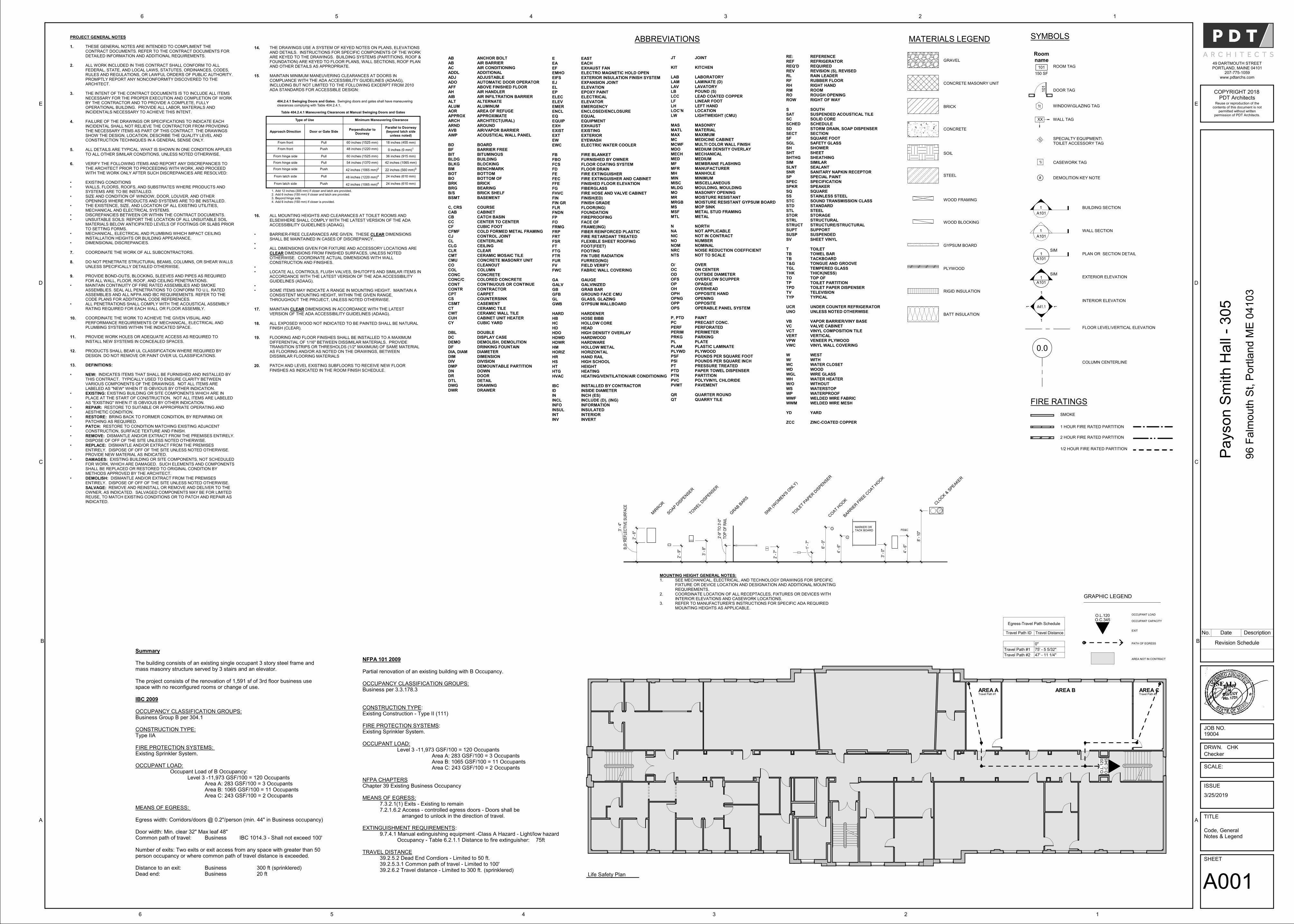
PROJECT GENERAL NOTES
1. THESE GENERAL NOTES ARE INTENDED TO COMPLIMENT THE CONTRACT DOCUMENTS. REFER TO THE CONTRACT DOCUMENTS FOR DETAILED INFORMATION AND ADDITIONAL REQUIREMENTS.
2. ALL WORK INCLUDED IN THIS CONTRACT SHALL CONFORM TO ALL FEDERAL, STATE, AND LOCAL LAWS, STATUTES, ORDINANCES, CODES, RULES AND REGULATIONS, OR LAWFUL ORDERS OF PUBLIC AUTHORITY. PROMPTLY REPORT ANY NONCONFORMITY DISCOVERED TO THE ARCHITECT.
3. THE INTENT OF THE CONTRACT DOCUMENTS IS TO INCLUDE ALL ITEMS NECESSARY FOR THE PROPER EXECUTION AND COMPLETION OF WORK BY THE CONTRACTOR AND TO PROVIDE A COMPLETE, FULLY OPERATIONAL BUILDING. PROVIDE ALL LABOR, MATERIALS AND INCIDENTALS NECESSARY TO ACHIEVE THIS INTENT.
4. FAILURE OF THE DRAWINGS OR SPECIFICATIONS TO INDICATE EACH INCIDENTAL SHALL NOT RELIEVE THE CONTRACTOR FROM PROVIDING THE NECESSARY ITEMS AS PART OF THIS CONTRACT. THE DRAWINGS SHOW THE DESIGN, LOCATION, DESCRIBE THE QUALITY LEVEL AND CONSTRUCTION TECHNIQUES IN A GENERAL SENSE ONLY.
5. ALL DETAILS ARE TYPICAL. WHAT IS SHOWN IN ONE CONDITION APPLIES TO ALL OTHER SIMILAR CONDITIONS, UNLESS NOTED OTHERWISE.
6. VERIFY THE FOLLOWING ITEMS AND REPORT ANY DISCREPANCIES TO THE ARCHITECT PRIOR TO PROCEEDING WITH WORK, AND PROCEED WITH THE WORK ONLY AFTER SUCH DISCREPANCIES ARE RESOLVED:
• EXISTING CONDITIONS• WALLS, FLOORS, ROOFS, AND SUBSTRATES WHERE PRODUCTS AND
SYSTEMS ARE TO BE INSTALLED.• SIZE AND CONDITION OF WINDOW, DOOR, LOUVER, AND OTHER
OPENINGS WHERE PRODUCTS AND SYSTEMS ARE TO BE INSTALLED. • THE EXISTENCE, SIZE, AND LOCATION OF ALL EXISTING UTILITIES,
MECHANICAL AND ELECTRICAL SYSTEMS.• DISCREPANCIES BETWEEN OR WITHIN THE CONTRACT DOCUMENTS. • UNSUITABLE SOILS: REPORT THE LOCATION OF ALL UNSUITABLE SOIL
MATERIALS BELOW ANTICIPATED LEVELS OF FOOTINGS OR SLABS PRIOR TO SETTING FORMS.
• MECHANICAL, ELECTRICAL AND PLUMBING WHICH IMPACT CEILING INSTALLATION HEIGHTS OR BUILDING APPEARANCE.
• DIMENSIONAL DISCREPANCIES.
7. COORDINATE THE WORK OF ALL SUBCONTRACTORS.
8. DO NOT PENETRATE STRUCTURAL BEAMS, COLUMNS, OR SHEAR WALLS UNLESS SPECIFICALLY DETAILED OTHERWISE.
9. PROVIDE BOND-OUTS, BLOCKING, SLEEVES AND PIPES AS REQUIRED FOR ALL WALL, FLOOR, ROOF, AND CEILING PENETRATIONS.
• MAINTAIN CONTINUITY OF FIRE RATED ASSEMBLIES AND SMOKE ASSEMBLIES. SEAL ALL PENETRATIONS TO CONFORM TO U.L. RATED ASSEMBLIES AND ALL NFPA AND IBC REQUIREMENTS. REFER TO THE CODE PLANS FOR ADDITIONAL CODE REFERENCES.
• ALL PENETRATIONS SHALL COMPLY WITH THE ACOUSTICAL ASSEMBLY RATING REQUIRED FOR EACH WALL OR FLOOR ASSEMBLY.
10. COORDINATE THE WORK TO ACHIEVE THE GIVEN VISUAL AND PERFORMANCE REQUIREMENTS OF MECHANICAL, ELECTRICAL AND PLUMBING SYSTEMS WITHIN THE INDICATED SPACE.
11. PROVIDE WORK HOLES OR ADEQUATE ACCESS AS REQUIRED TO INSTALL NEW SYSTEMS IN CONCEALED SPACES.
12. PRODUCTS SHALL BEAR UL CLASSIFICATION WHERE REQUIRED BY DESIGN. DO NOT REMOVE OR PAINT OVER UL CLASSIFICATIONS.
13. DEFINITIONS:
• NEW: INDICATES ITEMS THAT SHALL BE FURNISHED AND INSTALLED BY THIS CONTRACT. TYPICALLY USED TO ENSURE CLARITY BETWEEN VARIOUS COMPONENTS OF THE DRAWINGS. NOT ALL ITEMS ARE LABELED AS "NEW" WHEN IT IS OBVIOUS BY OTHER INDICATION.
• EXISTING: EXISTING BUILDING OR SITE COMPONENTS WHICH ARE IN PLACE AT THE START OF CONSTRUCTION. NOT ALL ITEMS ARE LABELED AS "EXISTING" WHEN IT IS OBVIOUS BY OTHER INDICATION.
• REPAIR: RESTORE TO SUITABLE OR APPROPRIATE OPERATING AND AESTHETIC CONDITION.
• RESTORE: BRING BACK TO FORMER CONDITION, BY REPAIRING OR PATCHING AS REQUIRED.
• PATCH: RESTORE TO CONDITION MATCHING EXISTING ADJACENT CONSTRUCTION, SURFACE TEXTURE AND FINISH.
• REMOVE: DISMANTLE AND/OR EXTRACT FROM THE PREMISES ENTIRELY. DISPOSE OF OFF OF THE SITE UNLESS NOTED OTHERWISE.
• REPLACE: DISMANTLE AND/OR EXTRACT FROM THE PREMISES ENTIRELY. DISPOSE OF OFF OF THE SITE UNLESS NOTED OTHERWISE. PROVIDE NEW MATERIAL AS INDICATED.
• DAMAGES: EXISTING BUILDING OR SITE COMPONENTS, NOT SCHEDULED FOR WORK, WHICH ARE DAMAGED. SUCH ELEMENTS AND COMPONENTS SHALL BE REPLACED OR RESTORED TO ORIGINAL CONDITION BY METHODS APPROVED BY THE ARCHITECT.
• DEMOLISH: DISMANTLE AND/OR EXTRACT FROM THE PREMISES ENTIRELY. DISPOSE OF OFF OF THE SITE UNLESS NOTED OTHERWISE.
SALVAGE: REMOVE AND REINSTALL OR REMOVE AND DELIVER TO THE OWNER, AS INDICATED. SALVAGED COMPONENTS MAY BE FOR LIMITED REUSE, TO MATCH EXISTING CONDITIONS OR TO PATCH AND REPAIR AS INDICATED.
MATERIALS LEGEND
GRAVEL
CONCRETE MASONRY UNIT
BRICK
CONCRETE
SOIL
STEEL
WOOD FRAMING
WOOD BLOCKING
GYPSUM BOARD
PLYWOOD
BATT INSULATION
RIGID INSULATION
AB
AB
ACADDL
ADJ
ADO
AFFAH
AIB
ALT
ALUMAOR
APPROX
ARCH
ARNDAVB
AWP
BDBF
BIT
BLDG
BLKGBM
BOT
BO
BRKBRG
B/S
BSMT
C, CRS
CAB
CB
CCCF
CFMF
CJCL
CLG
CLR
CMTCMU
CO
COL
CONCCONC/C
CONT
CONTR
CPTCS
CSMT
CT
CWTCUH
CY
DBLDC
DEMO
DF
DIA, DIAMDIM
DIV
DMP
DNDR
DTL
DWG
DWR
RE:
REFREQ’D
REV
RLRF
RH
RM
ROROW
S
SATSC
SCHED
SD
SECTSF
SGL
SH
SHTSHTHG
SIM
SLNT
SNRSP
SPEC
SPKR
SQSS
STC
STD
STLSTOR
STRL
STRUCT
SUPTSUSP
SV
TTB
TB
T&G
TGLTHK
TO
TPTPD
TV
TYP
UCR
UNO
VBVC
VCT
VERT
VPWVWC
W
W/WC
WD
WGL
WHW/O
WS
WP
WWFWWM
YD
ZCC
ANCHOR BOLT
AIR BARRIER
AIR CONDITIONINGADDITIONAL
ADJUSTABLE
AUTOMATIC DOOR OPERATOR
ABOVE FINISHED FLOORAIR HANDLER
AIR INFILTRATION BARRIER
ALTERNATE
ALUMINUMAREA OF REFUGE
APPROXIMATE
ARCHITECT(URAL)
AROUNDAIR/VAPOR BARRIER
ACOUSTICAL WALL PANEL
BOARDBARRIER FREE
BITUMINOUS
BUILDING
BLOCKINGBENCHMARK
BOTTOM
BOTTOM OF
BRICKBEARING
BRICK SHELF
BASEMENT
COURSE
CABINET
CATCH BASIN
CENTER TO CENTERCUBIC FOOT
COLD FORMED METAL FRAMING
CONTROL JOINTCENTERLINE
CEILING
CLEAR
CERAMIC MOSAIC TILECONCRETE MASONRY UNIT
CLEANOUT
COLUMN
CONCRETECOLORED CONCRETE
CONTINUOUS OR CONTINUE
CONTRACTOR
CARPETCOUNTERSINK
CASEMENT
CERAMIC TILE
CERAMIC WALL TILECABINET UNIT HEATER
CUBIC YARD
DOUBLEDISPLAY CASE
DEMOLISH, DEMOLITION
DRINKING FOUNTAIN
DIAMETERDIMENSION
DIVISION
DEMOUNTABLE PARTITION
DOWNDOOR
DETAIL
DRAWING
DRAWER
REFERENCE
REFRIGERATORREQUIRED
REVISION (S), REVISED
RAIN LEADERRUBBER FLOOR
RIGHT HAND
ROOM
ROUGH OPENINGRIGHT OF WAY
SOUTH
SUSPENDED ACOUSTICAL TILESOLID CORE
SCHEDULE
STORM DRAIN, SOAP DISPENSER
SECTIONSQUARE FOOT
SAFETY GLASS
SHOWER
SHEETSHEATHING
SIMILAR
SEALANT
SANITARY NAPKIN RECEPTORSPECIAL PAINT
SPECIFICATION
SPEAKER
SQUARESTAINLESS STEEL
SOUND TRANSMISSION CLASS
STANDARD
STEELSTORAGE
STRUCTURAL
STRUCTURE/STRUCTURAL
SUPPORTSUSPENDED
SHEET VINYL
TOILET TOWEL BAR
TACKBOARD
TONGUE AND GROOVE
TEMPERED GLASSTHICK(NESS)
TOP OF
TOILET PARTITIONTOILET PAPER DISPENSER
TELEVISION
TYPICAL
UNDER COUNTER REFRIGERATOR
UNLESS NOTED OTHERWISE
VAPOR BARRIER/VINY BASEVALVE CABINET
VINYL COMPOSITION TILE
VERTICAL
VENEER PLYWOODVINYL WALL COVERING
WEST
WITHWATER CLOSET
WOOD
WIRE GLASS
WATER HEATERWITHOUT
WATERSTOP
WATERPROOF
WELDED WIRE FABRICWELDED WIRE MESH
YARD
ZINC-COATED COPPER
ABBREVIATIONS
E
EA
EFEMHO
EIFS
EJ
ELEP
ELEC
ELEV
EMERENCL
EQ
EQUIP
EXHEXIST
EXT
EW
EWC
FB
FBO
FCSFD
FE
FEC
FFEFG
FHVC
FIN
FIN GRFLR
FNDN
FP
FOFRMG
FRP
FRT
FSRFT
FTG
FTR
FURFV
FWC
GAGALV
GB
GFB
GLGWB
HARD
HBHC
HD
HDO
HDWDHDWR
HM
HORIZ
HRHS
HT
HTG
HVAC
IBC
ID
ININCL
INFO
INSUL
INTINV
EAST
EACH
EXHAUST FANELECTRO MAGNETIC HOLD OPEN
EXTERIOR INSULATION FINISH SYSTEM
EXPANSION JOINT
ELEVATIONEPOXY PAINT
ELECTRICAL
ELEVATOR
EMERGENCYENCLOSED/ENCLOSURE
EQUAL
EQUIPMENT
EXHAUSTEXISTING
EXTERIOR
EYEWASH
ELECTRIC WATER COOLER
FIRE BLANKET
FURNISHED BY OWNER
FLOOR COATING SYSTEMFLOOR DRAIN
FIRE EXTINGUISHER
FIRE EXTINGUISHER AND CABINET
FINISHED FLOOR ELEVATIONFIBERGLASS
FIRE HOSE AND VALVE CABINET
FINISH(ED)
FINISH GRADEFLOOR(ING)
FOUNDATION
FIREPROOFING
FACE OFFRAME(ING)
FIBER REINFORCED PLASTIC
FIRE RETARDANT TREATED
FLEXIBLE SHEET ROOFINGFOOT(FEET)
FOOTING
FIN TUBE RADIATION
FURRED(ING)FIELD VERIFY
FABRIC WALL COVERING
GAUGEGALVINIZED
GRAB BAR
GROUND FACE CMU
GLASS, GLAZINGGYPSUM WALLBOARD
HARDENER
HOSE BIBBHOLLOW CORE
HEAD
HIGH DENSITY OVERLAY
HARDWOODHARDWARE
HOLLOW METAL
HORIZONTAL
HAND RAILHIGH SCHOOL
HEIGHT
HEATING
HEATING/VENTILATION/AIR CONDITIONING
INSTALLED BY CONTRACTOR
INSIDE DIAMETER
INCH (ES)INCLUDE (D), (ING)
INFORMATION
INSULATED
INTERIORINVERT
JT
KIT
LAB
LAM
LAVLB
LCC
LF
LHLOC’N
LW
MASMATL
MAX
MC
MCWFMDO
MECH
MED
MFMFR
MH
MIN
MISCMLDG
MO
MR
MRGBMS
MSF
MTL
N
NA
NIC
NONOM
NRC
NTS
O/
OC
OD
OFSOP
OH
OPH
OPNGOPP
OPS
P, PTDPC
PERF
PERIM
PRKGPL
PLAM
PLYWD
PSF
PSIPT
PTD
PTN
PVCPVMT
QR
QT
JOINT
KITCHEN
LABORATORY
LAMINATE (D)
LAVATORYPOUND (S)
LEAD COATED COPPER
LINEAR FOOT
LEFT HANDLOCATION
LIGHTWEIGHT (CMU)
MASONRYMATERIAL
MAXIMUM
MEDICINE CABINET
MULTI COLOR WALL FINISH MEDIUM DENSITY OVERLAY
MECHANICAL
MEDIUM
MEMBRANE FLASHING MANUFACTURER
MANHOLE
MINIMUM
MISCELLANEOUSMOULDING, MOULDING
MASONRY OPENING
MOISTURE RESISTANT
MOISTURE RESISTANT GYPSUM BOARDMOP SINK
METAL STUD FRAMING
METAL
NORTH
NOT APPLICABLE
NOT IN CONTRACT
NUMBERNOMINAL
NOISE REDUCTION COEFFICIENT
NOT TO SCALE
OVER
ON CENTER
OUTSIDE DIAMETER
OVERFLOW SCUPPER OPAQUE
OVERHEAD
OPPOSITE HAND
OPENINGOPPOSITE
OPERABLE PANEL SYSTEM
PAINTPRECAST CONC.
PERFORATED
PERIMETER
PARKINGPLATE
PLASTIC LAMINATE
PLYWOOD
POUNDS PER SQUARE FOOT
POUNDS PER SQUARE INCHPRESSURE TREATED
PAPER TOWEL DISPENSER
PARTITION
POLYVINYL CHLORIDEPAVEMENT
QUARTER ROUND
QUARRY TILE
SYMBOLS
101
ROOM TAG
DOOR TAG
1t WINDOW\GLAZING TAG
0.0
A41.1
1
1
1
1
FIRE RATINGS
SMOKE
1 HOUR FIRE RATED PARTITION
2 HOUR FIRE RATED PARTITION
1/2 HOUR FIRE RATED PARTITION
WALL TAG
A101
1SIM
BUILDING SECTION
WALL SECTION
PLAN OR SECTION DETAIL
INTERIOR ELEVATION
EXTERIOR ELEVATION
A101
1SIM
FLOOR LEVEL\VERTICAL ELEVATION
COLUMN CENTERLINE
Roomname
101
150 SF
SPECIALTY EQUIPMENT\TOILET ACCESSORY TAG
CASEWORK TAG
1i
1i
DEMOLITION KEY NOTE#
XX
1
A101
1
A101
14. THE DRAWINGS USE A SYSTEM OF KEYED NOTES ON PLANS, ELEVATIONS AND DETAILS. INSTRUCTIONS FOR SPECIFIC COMPONENTS OF THE WORK ARE KEYED TO THE DRAWINGS. BUILDING SYSTEMS (PARTITIONS, ROOF & FOUNDATION) ARE KEYED TO FLOOR PLANS, WALL SECTIONS, ROOF PLAN AND OTHER DETAILS AS APPROPRIATE.
15. MAINTAIN MINIMUM MANEUVERING CLEARANCES AT DOORS IN COMPLIANCE WITH THE ADA ACCESSIBILITY GUIDELINES (ADAAG), INCLUDING BUT NOT LIMITED TO THE FOLLOWING EXCERPT FROM 2010 ADA STANDARDS FOR ACCESSIBLE DESIGN:
16. ALL MOUNTING HEIGHTS AND CLEARANCES AT TOILET ROOMS AND ELSEWHERE SHALL COMPLY WITH THE LATEST VERSION OF THE ADA ACCESSIBILITY GUIDELINES (ADAAG).
• BARRIER-FREE CLEARANCES ARE GIVEN. THESE CLEAR DIMENSIONS SHALL BE MAINTAINED IN CASES OF DISCREPANCY.
• • ALL DIMENSIONS GIVEN FOR FIXTURE AND ACCESSORY LOCATIONS ARE
CLEAR DIMENSIONS FROM FINISHED SURFACES, UNLESS NOTED OTHERWISE. COORDINATE ACTUAL DIMENSIONS WITH WALL CONSTRUCTION AND FINISHES.
• • LOCATE ALL CONTROLS, FLUSH VALVES, SHUTOFFS AND SIMILAR ITEMS IN
ACCORDANCE WITH THE LATEST VERSION OF THE ADA ACCESSIBILITY GUIDELINES (ADAAG).
• • SOME ITEMS MAY INDICATE A RANGE IN MOUNTING HEIGHT. MAINTAIN A
CONSISTENT MOUNTING HEIGHT, WITHIN THE GIVEN RANGE, THROUGHOUT THE PROJECT, UNLESS NOTED OTHERWISE.
17. MAINTAIN CLEAR DIMENSIONS IN ACCORDANCE WITH THE LATEST VERSION OF THE ADA ACCESSIBILITY GUIDELINES (ADAAG).
18. ALL EXPOSED WOOD NOT INDICATED TO BE PAINTED SHALL BE NATURAL FINISH (CLEAR).
19. FLOORING AND FLOOR FINISHES SHALL BE INSTALLED TO A MAXIMUM DIFFERENTIAL OF 1/16" BETWEEN DISSIMILAR MATERIALS. PROVIDE TRANSITION STRIPS OR THRESHOLDS (1/2" MAXIMUM) OF SAME MATERIAL AS FLOORING AND/OR AS NOTED ON THE DRAWINGS, BETWEEN DISSIMILAR FLOORING MATERIALS
20. PATCH AND LEVEL EXISTING SUBFLOORS TO RECEIVE NEW FLOOR FINISHES AS INDICATED IN THE ROOM FINISH SCHEDULE.
O.C
.345
O.L
.120
Travel Path #1AREA A
Travel Path #2AREA CAREA B
FE&CMARKER OR TACK BOARD
COAT H
OOK
BARRIE
R F
REE
COAT H
OOK
4' -
6"
3' -
0"
4' -
6"
6' -
0"
MOUNTING HEIGHT GENERAL NOTES:1. SEE MECHANICAL, ELECTRICAL, AND TECHNOLOGY DRAWINGS FOR SPECIFIC
FIXTURE OR DEVICE LOCATION AND DESIGNATION AND ADDITIONAL MOUNTING REQUIREMENTS.
2. COORDINATE LOCATION OF ALL RECEPTACLES, FIXTURES OR DEVICES WITH INTERIOR ELEVATIONS AND CASEWORK LOCATIONS.
3. REFER TO MANUFACTURER'S INSTRUCTIONS FOR SPECIFIC ADA REQUIRED MOUNTING HEIGHTS AS APPLICABLE.
CLO
CK &
SPEA
KER
8' -
10"
3' -
8"B.O
. R
EF
LE
CT
IVE
SU
RF
AC
E
3' -
4"
2' -
6"
MIR
ROR
SOAP D
ISPE
NSER
TOW
EL
DIS
PEN
SER
2' -
9"
TO
P O
F R
AIL
2'-9
" T
O 3
'-0"
2' -
7"
GRAB
BAR
S
SNR (W
OM
EN'S
ONLY
)
TOIL
ET P
APE
R D
ISPEN
SER
1' -
7"
O.C.345O.L.120
Summary
The building consists of an existing single occupant 3 story steel frame and mass masonry structure served by 3 stairs and an elevator.
The project consists of the renovation of 1,591 sf of 3rd floor business use space with no reconfigured rooms or change of use.
IBC 2009
OCCUPANCY CLASSIFICATION GROUPS:Business Group B per 304.1
CONSTRUCTION TYPE:Type IIA
FIRE PROTECTION SYSTEMS: Existing Sprinkler System.
OCCUPANT LOAD:Occupant Load of B Occupancy:
Level 3 -11,973 GSF/100 = 120 OccupantsArea A: 283 GSF/100 = 3 OccupantsArea B: 1065 GSF/100 = 11 OccupantsArea C: 243 GSF/100 = 2 Occupants
MEANS OF EGRESS:
Egress width: Corridors/doors @ 0.2"/person (min. 44" in Business occupancy)
Door width: Min. clear 32" Max leaf 48"Common path of travel: Business IBC 1014.3 - Shall not exceed 100'
Number of exits: Two exits or exit access from any space with greater than 50 person occupancy or where common path of travel distance is exceeded.
Distance to an exit: Business 300 ft (sprinklered)Dead end: Business 20 ft
NFPA 101 2009
Partial renovation of an existing building with B Occupancy.
OCCUPANCY CLASSIFICATION GROUPS:Business per 3.3.178.3
CONSTRUCTION TYPE:Existing Construction - Type II (111)
FIRE PROTECTION SYSTEMS:Existing Sprinkler System.
OCCUPANT LOAD:Level 3 -11,973 GSF/100 = 120 Occupants
Area A: 283 GSF/100 = 3 OccupantsArea B: 1065 GSF/100 = 11 OccupantsArea C: 243 GSF/100 = 2 Occupants
NFPA CHAPTERSChapter 39 Existing Business Occupancy
MEANS OF EGRESS:7.3.2.1(1) Exits - Existing to remain7.2.1.6.2 Access - controlled egress doors - Doors shall be
arranged to unlock in the direction of travel.
EXTINGUISHMENT REQUIREMENTS:9.7.4.1 Manual extinguishing equipment -Class A Hazard - Light/low hazard
Occupancy - Table 6.2.1.1 Distance to fire extinguisher: 75ft
TRAVEL DISTANCE39.2.5.2 Dead End Corrdiors - Limited to 50 ft. 39.2.5.3.1 Common path of travel - Limited to 100'39.2.6.2 Travel distance - Limited to 300 ft. (sprinklered)
SHEET
TITLE
ISSUE
SCALE:
JOB NO.
DRWN. CHK
PDT ArchitectsCOPYRIGHT 2018
49 DARTMOUTH STREETPORTLAND, MAINE 04101
207-775-1059www.pdtarchs.com
Reuse or reproduction of thecontents of this document is not
permitted without writtenpermission of PDT Architects.
123456
A
B
C
D
E
A
B
C
D
E
123456
Payson
Sm
ith
Ha
ll -
305
96 F
alm
ou
th S
t, P
ort
lan
d M
E 0
410
3
Code, GeneralNotes & Legend
A001
3/25/2019
19004
Checker
Revision Schedule
No. Date Description
Life Safety Plan
Egress-Travel Path Schedule
Travel Path ID Travel Distance
0"
Travel Path #1 75' - 5 5/32"
Travel Path #2 47' - 11 1/4"
GRAPHIC LEGEND
OCCUPANT LOAD
OCCUPANT CAPACITY
EXIT
PATH OF EGRESS
AREA NOT IN CONTRACT
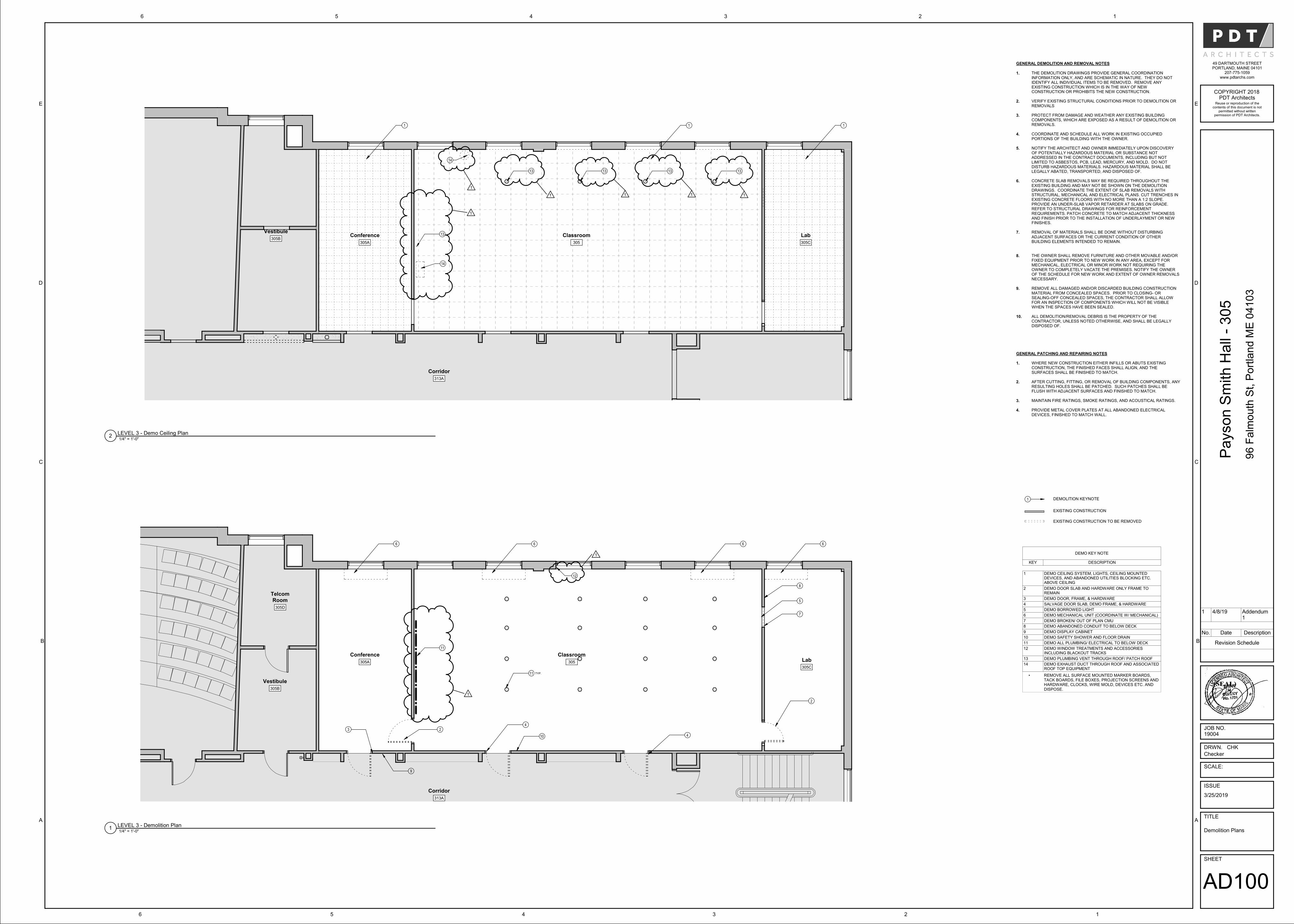
Corridor
313A
Conference
305A Lab
305C
TelcomRoom
305D
Vestibule
305B
2
4
4
3 2
5
666
7
8
9
10
Classroom
305
6
11 TYP.
12
1
11
1
GENERAL DEMOLITION AND REMOVAL NOTES
1. THE DEMOLITION DRAWINGS PROVIDE GENERAL COORDINATION INFORMATION ONLY, AND ARE SCHEMATIC IN NATURE. THEY DO NOT IDENTIFY ALL INDIVIDUAL ITEMS TO BE REMOVED. REMOVE ANY EXISTING CONSTRUCTION WHICH IS IN THE WAY OF NEW CONSTRUCTION OR PROHIBITS THE NEW CONSTRUCTION.
2. VERIFY EXISTING STRUCTURAL CONDITIONS PRIOR TO DEMOLITION OR REMOVALS
3. PROTECT FROM DAMAGE AND WEATHER ANY EXISTING BUILDING COMPONENTS, WHICH ARE EXPOSED AS A RESULT OF DEMOLITION OR REMOVALS.
4. COORDINATE AND SCHEDULE ALL WORK IN EXISTING OCCUPIED PORTIONS OF THE BUILDING WITH THE OWNER.
5. NOTIFY THE ARCHITECT AND OWNER IMMEDIATELY UPON DISCOVERY OF POTENTIALLY HAZARDOUS MATERIAL OR SUBSTANCE NOT ADDRESSED IN THE CONTRACT DOCUMENTS, INCLUDING BUT NOT LIMITED TO ASBESTOS, PCB, LEAD, MERCURY, AND MOLD. DO NOT DISTURB HAZARDOUS MATERIALS. HAZARDOUS MATERIAL SHALL BE LEGALLY ABATED, TRANSPORTED, AND DISPOSED OF.
6. CONCRETE SLAB REMOVALS MAY BE REQUIRED THROUGHOUT THE EXISTING BUILDING AND MAY NOT BE SHOWN ON THE DEMOLITION DRAWINGS. COORDINATE THE EXTENT OF SLAB REMOVALS WITH STRUCTURAL, MECHANICAL AND ELECTRICAL PLANS. CUT TRENCHES IN EXISTING CONCRETE FLOORS WITH NO MORE THAN A 1:2 SLOPE. PROVIDE AN UNDER-SLAB VAPOR RETARDER AT SLABS ON GRADE. REFER TO STRUCTURAL DRAWINGS FOR REINFORCEMENT REQUIREMENTS. PATCH CONCRETE TO MATCH ADJACENT THICKNESS AND FINISH PRIOR TO THE INSTALLATION OF UNDERLAYMENT OR NEW FINISHES.
7. REMOVAL OF MATERIALS SHALL BE DONE WITHOUT DISTURBING ADJACENT SURFACES OR THE CURRENT CONDITION OF OTHER BUILDING ELEMENTS INTENDED TO REMAIN.
8. THE OWNER SHALL REMOVE FURNITURE AND OTHER MOVABLE AND/OR FIXED EQUIPMENT PRIOR TO NEW WORK IN ANY AREA, EXCEPT FOR MECHANICAL, ELECTRICAL OR MINOR WORK NOT REQUIRING THE OWNER TO COMPLETELY VACATE THE PREMISES. NOTIFY THE OWNER OF THE SCHEDULE FOR NEW WORK AND EXTENT OF OWNER REMOVALS NECESSARY.
9. REMOVE ALL DAMAGED AND/OR DISCARDED BUILDING CONSTRUCTION MATERIAL FROM CONCEALED SPACES. PRIOR TO CLOSING- OR SEALING-OFF CONCEALED SPACES, THE CONTRACTOR SHALL ALLOW FOR AN INSPECTION OF COMPONENTS WHICH WILL NOT BE VISIBLE WHEN THE SPACES HAVE BEEN SEALED.
10. ALL DEMOLITION/REMOVAL DEBRIS IS THE PROPERTY OF THE CONTRACTOR, UNLESS NOTED OTHERWISE, AND SHALL BE LEGALLY DISPOSED OF.
Corridor
313A
Conference
305A
Vestibule
305BClassroom
305
Lab
305C
1 11
13 13 13 13
14
14
1 1 1 1
13
1
1
GENERAL PATCHING AND REPAIRING NOTES
1. WHERE NEW CONSTRUCTION EITHER INFILLS OR ABUTS EXISTING CONSTRUCTION, THE FINISHED FACES SHALL ALIGN, AND THE SURFACES SHALL BE FINISHED TO MATCH.
2. AFTER CUTTING, FITTING, OR REMOVAL OF BUILDING COMPONENTS, ANY RESULTING HOLES SHALL BE PATCHED. SUCH PATCHES SHALL BE FLUSH WITH ADJACENT SURFACES AND FINISHED TO MATCH.
3. MAINTAIN FIRE RATINGS, SMOKE RATINGS, AND ACOUSTICAL RATINGS.
4. PROVIDE METAL COVER PLATES AT ALL ABANDONED ELECTRICAL DEVICES, FINISHED TO MATCH WALL.
1 DEMOLITION KEYNOTE
EXISTING CONSTRUCTION
EXISTING CONSTRUCTION TO BE REMOVED
SHEET
TITLE
ISSUE
SCALE:
JOB NO.
DRWN. CHK
PDT ArchitectsCOPYRIGHT 2018
49 DARTMOUTH STREETPORTLAND, MAINE 04101
207-775-1059www.pdtarchs.com
Reuse or reproduction of thecontents of this document is not
permitted without writtenpermission of PDT Architects.
123456
A
B
C
D
E
A
B
C
D
E
123456
Payson
Sm
ith
Ha
ll -
305
96 F
alm
ou
th S
t, P
ort
lan
d M
E 0
410
3
Demolition Plans
AD100
3/25/2019
19004
Checker
1/4" = 1'-0"1
LEVEL 3 - Demolition Plan
DEMO KEY NOTE
KEY DESCRIPTION
1 DEMO CEILING SYSTEM, LIGHTS, CEILING MOUNTEDDEVICES, AND ABANDONED UTILITIES BLOCKING ETC.ABOVE CEILING
2 DEMO DOOR SLAB AND HARDWARE ONLY FRAME TOREMAIN
3 DEMO DOOR, FRAME, & HARDWARE
4 SALVAGE DOOR SLAB, DEMO FRAME, & HARDWARE
5 DEMO BORROWED LIGHT
6 DEMO MECHANICAL UNIT (COORDINATE W/ MECHANICAL)
7 DEMO BROKEN/ OUT OF PLAN CMU
8 DEMO ABANDONED CONDUIT TO BELOW DECK
9 DEMO DISPLAY CABINET
10 DEMO SAFETY SHOWER AND FLOOR DRAIN
11 DEMO ALL PLUMBING/ ELECTRICAL TO BELOW DECK
12 DEMO WINDOW TREATMENTS AND ACCESSORIESINCLUDING BLACKOUT TRACKS
13 DEMO PLUMBING VENT THROUGH ROOF/ PATCH ROOF
14 DEMO EXHAUST DUCT THROUGH ROOF AND ASSOCIATEDROOF TOP EQUIPMENT
1/4" = 1'-0"2
LEVEL 3 - Demo Ceiling Plan
• REMOVE ALL SURFACE MOUNTED MARKER BOARDS, TACK BOARDS, FILE BOXES, PROJECTION SCREENS AND HARDWARE, CLOCKS, WIRE MOLD, DEVICES ETC. AND DISPOSE.
Revision Schedule
No. Date Description
1 4/8/19 Addendum1
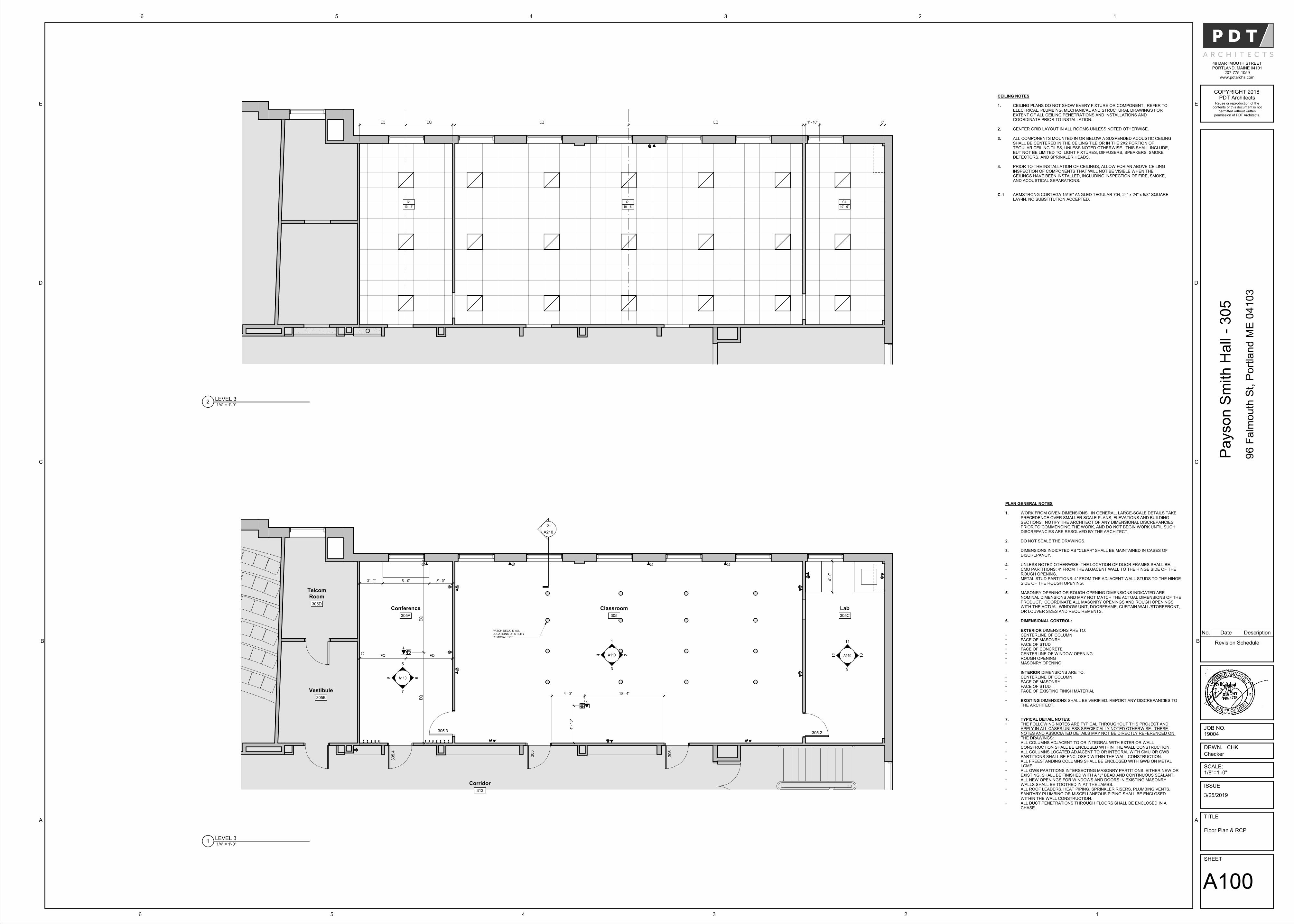
4
4
PLAN GENERAL NOTES
1. WORK FROM GIVEN DIMENSIONS. IN GENERAL, LARGE-SCALE DETAILS TAKE PRECEDENCE OVER SMALLER SCALE PLANS, ELEVATIONS AND BUILDING SECTIONS. NOTIFY THE ARCHITECT OF ANY DIMENSIONAL DISCREPANCIES PRIOR TO COMMENCING THE WORK, AND DO NOT BEGIN WORK UNTIL SUCH DISCREPANCIES ARE RESOLVED BY THE ARCHITECT.
2. DO NOT SCALE THE DRAWINGS.
3. DIMENSIONS INDICATED AS "CLEAR" SHALL BE MAINTAINED IN CASES OF DISCREPANCY.
4. UNLESS NOTED OTHERWISE, THE LOCATION OF DOOR FRAMES SHALL BE:• CMU PARTITIONS: 4" FROM THE ADJACENT WALL TO THE HINGE SIDE OF THE
ROUGH OPENING.• METAL STUD PARTITIONS: 4" FROM THE ADJACENT WALL STUDS TO THE HINGE
SIDE OF THE ROUGH OPENING.
5. MASONRY OPENING OR ROUGH OPENING DIMENSIONS INDICATED ARE NOMINAL DIMENSIONS AND MAY NOT MATCH THE ACTUAL DIMENSIONS OF THE PRODUCT. COORDINATE ALL MASONRY OPENINGS AND ROUGH OPENINGS WITH THE ACTUAL WINDOW UNIT, DOORFRAME, CURTAIN WALL/STOREFRONT, OR LOUVER SIZES AND REQUIREMENTS.
6. DIMENSIONAL CONTROL:
EXTERIOR DIMENSIONS ARE TO:• CENTERLINE OF COLUMN• FACE OF MASONRY• FACE OF STUD• FACE OF CONCRETE • CENTERLINE OF WINDOW OPENING• ROUGH OPENING• MASONRY OPENING
INTERIOR DIMENSIONS ARE TO:• CENTERLINE OF COLUMN• FACE OF MASONRY• FACE OF STUD• FACE OF EXISTING FINISH MATERIAL
• EXISTING DIMENSIONS SHALL BE VERIFIED. REPORT ANY DISCREPANCIES TO THE ARCHITECT.
7. TYPICAL DETAIL NOTES:• THE FOLLOWING NOTES ARE TYPICAL THROUGHOUT THIS PROJECT AND
APPLY IN ALL CASES UNLESS SPECIFICALLY NOTED OTHERWISE. THESE NOTES AND ASSOCIATED DETAILS MAY NOT BE DIRECTLY REFERENCED ON THE DRAWINGS:
• ALL COLUMNS ADJACENT TO OR INTEGRAL WITH EXTERIOR WALL CONSTRUCTION SHALL BE ENCLOSED WITHIN THE WALL CONSTRUCTION.
• ALL COLUMNS LOCATED ADJACENT TO OR INTEGRAL WITH CMU OR GWB PARTITIONS SHALL BE ENCLOSED WITHIN THE WALL CONSTRUCTION.
• ALL FREESTANDING COLUMNS SHALL BE ENCLOSED WITH GWB ON METAL LGMF.
• ALL GWB PARTITIONS INTERSECTING MASONRY PARTITIONS, EITHER NEW OR EXISTING, SHALL BE FINISHED WITH A "J" BEAD AND CONTINUOUS SEALANT.
• ALL NEW OPENINGS FOR WINDOWS AND DOORS IN EXISTING MASONRY WALLS SHALL BE TOOTHED IN AT THE JAMBS.
• ALL ROOF LEADERS, HEAT PIPING, SPRINKLER RISERS, PLUMBING VENTS, SANITARY PLUMBING OR MISCELLANEOUS PIPING SHALL BE ENCLOSED WITHIN THE WALL CONSTRUCTION.
• ALL DUCT PENETRATIONS THROUGH FLOORS SHALL BE ENCLOSED IN A CHASE.
Corridor
313
Vestibule
305B
Classroom
305
3
A210
Lab
305C
TelcomRoom
305D
Conference
305A
A110
3
A110 10
A110 6
7
8
5
4
1
2
11
12
9
305.4
305.3
305
305.1
305.2
4' -
10"
4' - 3" 10' - 4"
4' -
0"
3' - 0" 6' - 0" 3' - 0"
EQ EQ
EQ
EQ
PATCH DECK IN ALL LOCATIONS OF UTILITY REMOVAL TYP.
C1
10' - 6"
C1
10' - 6"
C1
10' - 6"
EQ EQ EQ EQ 1' - 10" 6"
CEILING NOTES
1. CEILING PLANS DO NOT SHOW EVERY FIXTURE OR COMPONENT. REFER TO ELECTRICAL, PLUMBING, MECHANICAL AND STRUCTURAL DRAWINGS FOR EXTENT OF ALL CEILING PENETRATIONS AND INSTALLATIONS AND COORDINATE PRIOR TO INSTALLATION.
2. CENTER GRID LAYOUT IN ALL ROOMS UNLESS NOTED OTHERWISE.
3. ALL COMPONENTS MOUNTED IN OR BELOW A SUSPENDED ACOUSTIC CEILING SHALL BE CENTERED IN THE CEILING TILE OR IN THE 2X2 PORTION OF TEGULAR CEILING TILES, UNLESS NOTED OTHERWISE. THIS SHALL INCLUDE, BUT NOT BE LIMITED TO, LIGHT FIXTURES, DIFFUSERS, SPEAKERS, SMOKE DETECTORS, AND SPRINKLER HEADS.
4. PRIOR TO THE INSTALLATION OF CEILINGS, ALLOW FOR AN ABOVE-CEILING INSPECTION OF COMPONENTS THAT WILL NOT BE VISIBLE WHEN THE CEILINGS HAVE BEEN INSTALLED, INCLUDING INSPECTION OF FIRE, SMOKE, AND ACOUSTICAL SEPARATIONS.
C-1 ARMSTRONG CORTEGA 15/16" ANGLED TEGULAR 704, 24" x 24" x 5/8" SQUARE LAY-IN. NO SUBSTITUTION ACCEPTED.
SHEET
TITLE
ISSUE
SCALE:
JOB NO.
DRWN. CHK
PDT ArchitectsCOPYRIGHT 2018
49 DARTMOUTH STREETPORTLAND, MAINE 04101
207-775-1059www.pdtarchs.com
Reuse or reproduction of thecontents of this document is not
permitted without writtenpermission of PDT Architects.
123456
A
B
C
D
E
A
B
C
D
E
123456
Payson
Sm
ith
Ha
ll -
305
96 F
alm
ou
th S
t, P
ort
lan
d M
E 0
410
3
Floor Plan & RCP
A100
3/25/2019
19004
Checker
1/8"=1'-0"
1/4" = 1'-0"1
LEVEL 3
1/4" = 1'-0"2
LEVEL 3
Revision Schedule
No. Date Description
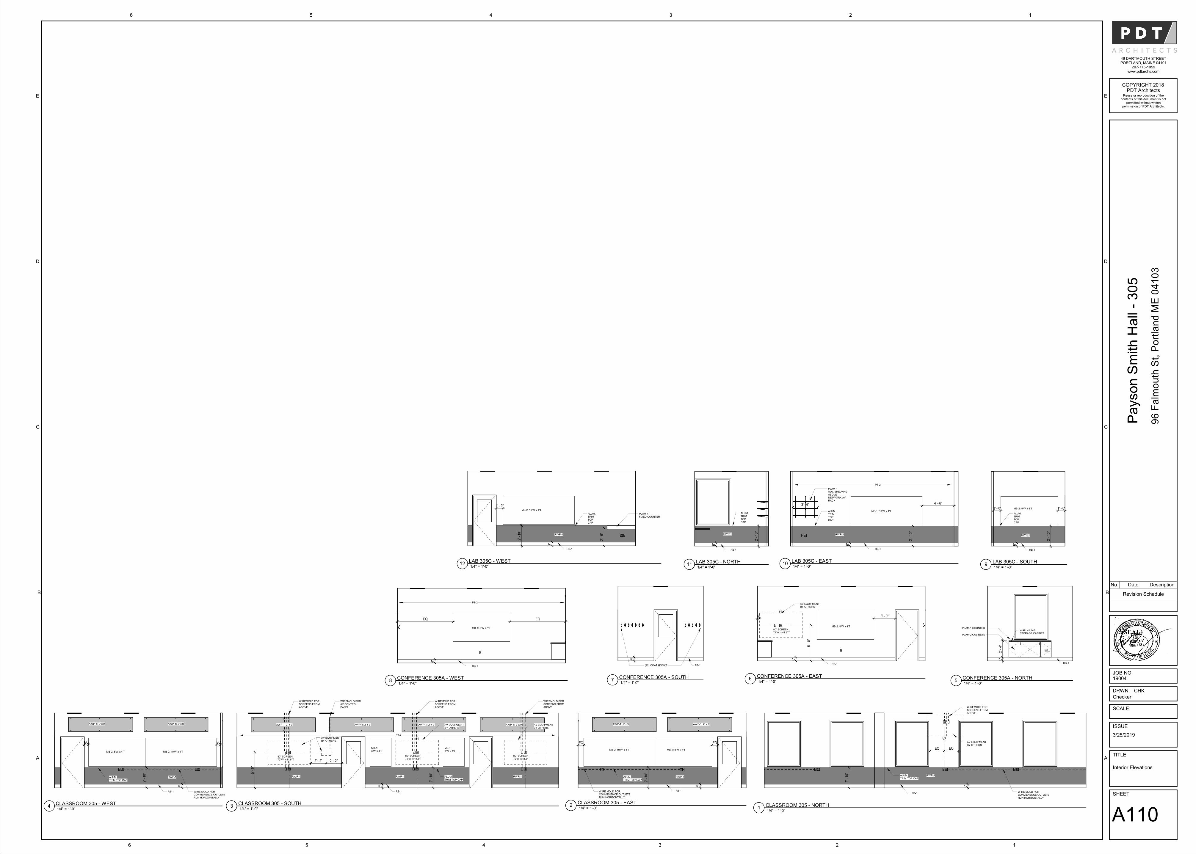
6"
2' -
10"
ALUM.TRIM TOP CAP
RWP-1
RB-1
EQEQ
AV EQUIPMENT BY OTHERS
WIREMOLD FOR SCREENS FROM ABOVE
WIRE MOLD FOR CONVIENENCE OUTLETS RUN HORIZONTALLY
MB-2: 10'W x 4'T
6"
MB-2: 8'W x 4'T
ALUM.TRIM TOP CAP
2' -
10"
EQ
RB-1
AWP-1: 2' x 9' AWP-1: 2' x 9'
RWP-1
EQ
WIRE MOLD FOR CONVIENENCE OUTLETS RUN HORIZONTALLY
80" SCREEN 72"W x 41.8"T
ALUM.TRIM TOP CAP
6"
2' -
10"
RWP-1
MB-1:3'W x 4'T
AWP-1: 2' x 9' AWP-1: 2' x 9' AWP-1: 2' x 9' AWP-1: 2' x 9'
RWP-1RWP-1
PT-2
80" SCREEN 72"W x 41.8"T
80" SCREEN 72"W x 41.8"T
MB-1: 3'W x 4'T
5' -
0"
2' - 2"2' - 2"
RB-1
AV EQUIPMENT BY OTHERS
AV EQUIPMENT BY OTHERS
AV EQUIPMENT BY OTHERS
WIREMOLD FOR SCREENS FROM ABOVE
WIREMOLD FOR SCREENS FROM ABOVE
WIREMOLD FOR SCREENS FROM ABOVE
WIREMOLD FOR AV CONTROL PANEL
MB-2: 10'W x 4'T
ALUM.TRIM TOP CAP 2
' - 1
0"
6"
EQ
RB-1
AWP-1: 2' x 9' AWP-1: 2' x 9'
RWP-1
MB-2: 8'W x 4'T
EQ
WIRE MOLD FOR CONVIENENCE OUTLETS RUN HORIZONTALLY
2' -
4"
6"
WALL-HUNG STORAGE CABINET
PLAM-1 COUNTER
PLAM-2 CABINETS
RB-1
6"
MB-2: 8'W x 4'T
3' - 0"4"
RB-1
80" SCREEN72"W x 41.8"T
5' -
0"
AV EQUIPMENT BY OTHERS
6"
(12) COAT HOOKS RB-1
6"
MB-1: 8'W x 4'T
EQEQ
PT-2
RB-1
6"
ALUM.TRIMTOPCAP
2' -
10"
MB-2: 8'W x 4'T
RWP-1
1' - 0" 1' - 0"
RB-1
MB-1: 10'W x 4'T
6"
ALUM.TRIMTOPCAP
2' -
10"
RWP-1
4' - 6"
PLAM-1ADJ. SHELVINGABOVENETWORK AVRACK
PT-2
RB-1
3' - 6"
6"
ALUM.TRIMTOPCAP
2' -
10"
RWP-1
RB-1
MB-2: 10'W x 4'T
6"
ALUM. TRIMTOPCAP
2' -
10"
RWP-1
1' - 0"
PLAM-1FIXED COUNTER
RB-1
2' -
6"
SHEET
TITLE
ISSUE
SCALE:
JOB NO.
DRWN. CHK
PDT ArchitectsCOPYRIGHT 2018
49 DARTMOUTH STREETPORTLAND, MAINE 04101
207-775-1059www.pdtarchs.com
Reuse or reproduction of thecontents of this document is not
permitted without writtenpermission of PDT Architects.
123456
A
B
C
D
E
A
B
C
D
E
123456
Payson
Sm
ith
Ha
ll -
305
96 F
alm
ou
th S
t, P
ort
lan
d M
E 0
410
3
Interior Elevations
A110
3/25/2019
19004
Checker
1/4" = 1'-0"1
CLASSROOM 305 - NORTH1/4" = 1'-0"
2CLASSROOM 305 - EAST
1/4" = 1'-0"3
CLASSROOM 305 - SOUTH1/4" = 1'-0"
4CLASSROOM 305 - WEST
1/4" = 1'-0"5
CONFERENCE 305A - NORTH1/4" = 1'-0"
6CONFERENCE 305A - EAST
1/4" = 1'-0"7
CONFERENCE 305A - SOUTH1/4" = 1'-0"
8CONFERENCE 305A - WEST
Revision Schedule
No. Date Description
1/4" = 1'-0"9
LAB 305C - SOUTH1/4" = 1'-0"
10LAB 305C - EAST
1/4" = 1'-0"11
LAB 305C - NORTH1/4" = 1'-0"
12LAB 305C - WEST
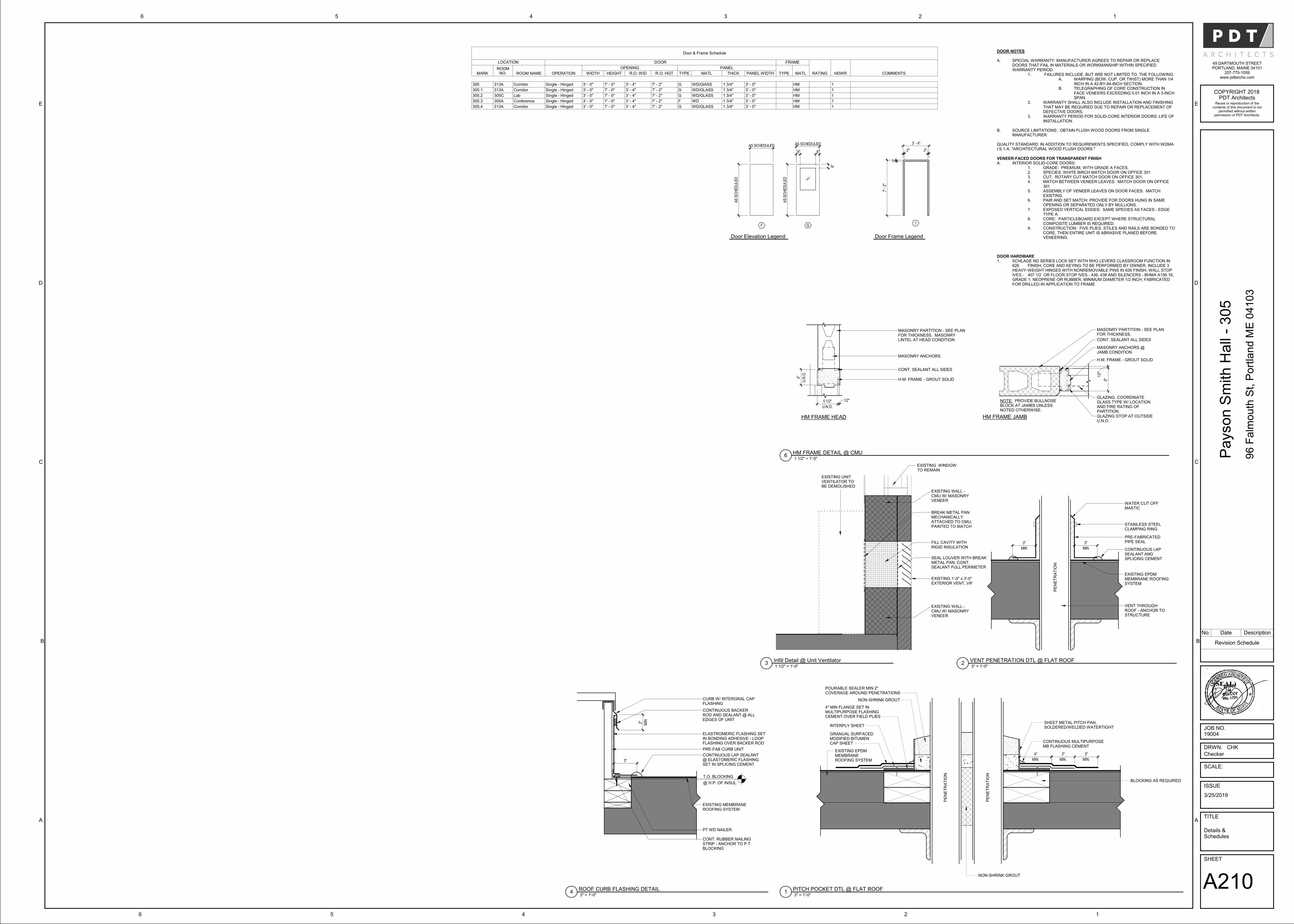
6"
6" 6"
GF
AS
SC
HE
DU
LE
D
AS SCHEDULED
AS
SC
HE
DU
LE
D
AS SCHEDULED
1
7' -
2"
2"
2" 2"
3' - 4"
MASONRY PARTITION - SEE PLAN FOR THICKNESS.
CONT. SEALANT ALL SIDES
H.M. FRAME - GROUT SOLID
MASONRY ANCHORS @ JAMB CONDITION
NOTE: PROVIDE BULLNOSE BLOCK AT JAMBS UNLESS NOTED OTHERWISE.
MASONRY PARTITION - SEE PLAN FOR THICKNESS. MASONRY LINTEL AT HEAD CONDITION
MASONRY ANCHORS
CONT. SEALANT ALL SIDES
H.M. FRAME - GROUT SOLID
U.N
.O.
4"
U.N.O.
5 1/2" 1/2"
HM FRAME HEAD HM FRAME JAMB
1/2
"
6"
GLAZING. COORDINATE GLASS TYPE W/ LOCATION AND FIRE RATING OF PARTITION.GLAZING STOP AT OUTSIDE U.N.O.
DOOR NOTES
A. SPECIAL WARRANTY: MANUFACTURER AGREES TO REPAIR OR REPLACE DOORS THAT FAIL IN MATERIALS OR WORKMANSHIP WITHIN SPECIFIED WARRANTY PERIOD.
1. FAILURES INCLUDE, BUT ARE NOT LIMITED TO, THE FOLLOWING: A. WARPING (BOW, CUP, OR TWIST) MORE THAN 1/4
INCH IN A 42-BY-84-INCH SECTION. B. TELEGRAPHING OF CORE CONSTRUCTION IN
FACE VENEERS EXCEEDING 0.01 INCH IN A 3-INCH SPAN.
2. WARRANTY SHALL ALSO INCLUDE INSTALLATION AND FINISHING THAT MAY BE REQUIRED DUE TO REPAIR OR REPLACEMENT OF DEFECTIVE DOORS.
3. WARRANTY PERIOD FOR SOLID-CORE INTERIOR DOORS: LIFE OF INSTALLATION.
B. SOURCE LIMITATIONS: OBTAIN FLUSH WOOD DOORS FROM SINGLE MANUFACTURER.
QUALITY STANDARD: IN ADDITION TO REQUIREMENTS SPECIFIED, COMPLY WITH WDMA I.S.1-A, "ARCHITECTURAL WOOD FLUSH DOORS."
VENEER-FACED DOORS FOR TRANSPARENT FINISH A. INTERIOR SOLID-CORE DOORS:
1. GRADE: PREMIUM, WITH GRADE A FACES. 2. SPECIES: WHITE BIRCH MATCH DOOR ON OFFICE 3013. CUT: ROTARY CUT MATCH DOOR ON OFFICE 301. 4. MATCH BETWEEN VENEER LEAVES: MATCH DOOR ON OFFICE
301 5. ASSEMBLY OF VENEER LEAVES ON DOOR FACES: MATCH
EXISTING. 6. PAIR AND SET MATCH: PROVIDE FOR DOORS HUNG IN SAME
OPENING OR SEPARATED ONLY BY MULLIONS. 7. EXPOSED VERTICAL EDGES: SAME SPECIES AS FACES - EDGE
TYPE A. 8. CORE: PARTICLEBOARD EXCEPT WHERE STRUCTURAL
COMPOSITE LUMBER IS REQUIRED. 9. CONSTRUCTION: FIVE PLIES. STILES AND RAILS ARE BONDED TO
CORE, THEN ENTIRE UNIT IS ABRASIVE PLANED BEFORE VENEERING.
DOOR HARDWARE 1. SCHLAGE ND SERIES LOCK SET WITH RHO LEVERS CLASSROOM FUNCTION IN
626 FINISH. CORE AND KEYING TO BE PERFORMED BY OWNER. INCLUDE 3 HEAVY-WEIGHT HINGES WITH NONREMOVABLE PINS IN 626 FINISH, WALL STOP IVES - 407 1/2 OR FLOOR STOP IVES - 436, 438 AND SILENCERS - BHMA A156.16, GRADE 1; NEOPRENE OR RUBBER, MINIMUM DIAMETER 1/2 INCH; FABRICATED FOR DRILLED-IN APPLICATION TO FRAME
SHEET METAL PITCH PAN, SOLDERED/WELDED WATERTIGHT
CONTINUOUS MULTIPURPOSE MB FLASHING CEMENT
NON-SHRINK GROUT
POURABLE SEALER MIN 2" COVERAGE AROUND PENETRATIONS
GRANUAL SURFACED MODIFIED BITUMEN CAP SHEET
NON-SHRINK GROUT
EXISTING EPDM MEMBRANE ROOFING SYSTEM MIN.
4"
MIN.
3"
MIN.
3"
INTERPLY SHEET
PE
NE
TR
AT
ION
PE
NE
TR
AT
ION
4" MIN FLANGE SET IN MULTIPURPOSE FLASHING CEMENT OVER FIELD PLIES
BLOCKING AS REQUIRED
MIN
3"
MIN
3"
WATER CUT OFF MASTIC
STAINLESS STEEL CLAMPING RING
PRE-FABRICATED PIPE SEAL
CONTINUOUS LAP SEALANT AND SPLICING CEMENT
EXISTING EPDM MEMBRANE ROOFING SYSTEM
VENT THROUGH ROOF - ANCHOR TO STRUCTURE
PE
NE
TR
AT
ION
EXISTING WALL -CMU W/ MASONRY VENEER
EXISTING UNIT VENTILATOR TO BE DEMOLISHED
EXISTING 1'-0" x 3'-0" EXTERIOR VENT, VIF
EXISTING WINDOW TO REMAIN
FILL CAVITY WITH RIGID INSULATION
EXISTING WALL -CMU W/ MASONRY VENEER
BREAK METAL PAN MECHANICALLY ATTACHED TO CMU, PAINTED TO MATCH
SEAL LOUVER WITH BREAK METAL PAN, CONT. SEALANT FULL PERIMETER
3"
CURB W/ INTERGRAL CAP FLASHING
CONTINUOUS BACKER ROD AND SEALANT @ ALL EDGES OF UNIT
ELASTROMERIC FLASHING SET IN BONDING ADHESIVE - LOOP FLASHING OVER BACKER ROD
CONTINUOUS LAP SEALANT @ ELASTOMERIC FLASHING SET IN SPLICING CEMENT
EXISTING MEMBRANE ROOFING SYSTEM
CONT. RUBBER NAILING STRIP - ANCHOR TO P.T. BLOCKING
MIN2"
T.O. BLOCKING
@ H.P. OF INSUL
PRE-FAB CURB UNIT
PT WD NAILER
SHEET
TITLE
ISSUE
SCALE:
JOB NO.
DRWN. CHK
PDT ArchitectsCOPYRIGHT 2018
49 DARTMOUTH STREETPORTLAND, MAINE 04101
207-775-1059www.pdtarchs.com
Reuse or reproduction of thecontents of this document is not
permitted without writtenpermission of PDT Architects.
123456
A
B
C
D
E
A
B
C
D
E
123456
Payson
Sm
ith
Ha
ll -
305
96 F
alm
ou
th S
t, P
ort
lan
d M
E 0
410
3
Details &Schedules
A210
3/25/2019
19004
Checker
Door & Frame Schedule
LOCATION DOOR FRAME
RATING HDWR COMMENTSMARKROOM
NO. ROOM NAME OPERATION
OPENING PANEL
TYPE MATLWIDTH HEIGHT R.O. WID R.O. HGT TYPE MATL THICK PANEL WIDTH
305 313A Corridor Single - Hinged 3' - 0" 7' - 0" 3' - 4" 7' - 2" G WD/GlASS 1 3/4" 3' - 0" HM 1
305.1 313A Corridor Single - Hinged 3' - 0" 7' - 0" 3' - 4" 7' - 2" G WD/GLASS 1 3/4" 3' - 0" HM 1
305.2 305C Lab Single - Hinged 3' - 0" 7' - 0" 3' - 4" 7' - 2" G WD/GLASS 1 3/4" 3' - 0" HM 1
305.3 305A Conference Single - Hinged 3' - 0" 7' - 0" 3' - 4" 7' - 2" F WD 1 3/4" 3' - 0" HM 1
305.4 313A Corridor Single - Hinged 3' - 0" 7' - 0" 3' - 4" 7' - 2" G WD/GLASS 1 3/4" 3' - 0" HM 1
Door Elevation Legend Door Frame Legend
1 1/2" = 1'-0"6
HM FRAME DETAIL @ CMU
Revision Schedule
No. Date Description
3" = 1'-0"1
PITCH POCKET DTL @ FLAT ROOF
3" = 1'-0"2
VENT PENETRATION DTL @ FLAT ROOF1 1/2" = 1'-0"
3Infill Detail @ Unit Ventilator
3" = 1'-0"4
ROOF CURB FLASHING DETAIL
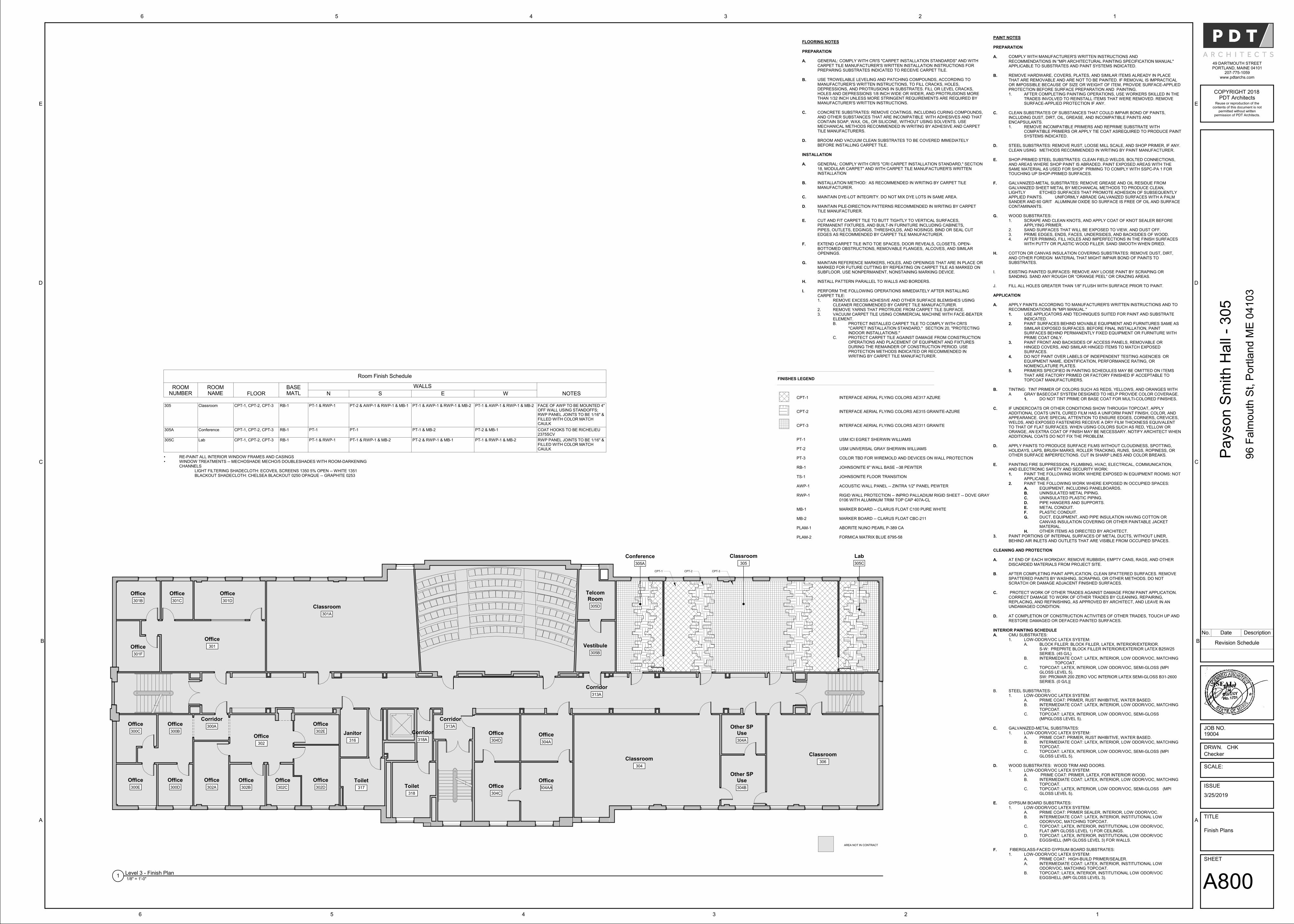
Office
301F
Office
301
Corridor
300AOffice
300B
Office
300C
Office
300E
Office
300D
Office
304D
Office
304AAOffice
304C
Office
301B
Office
301C
Office
301D
AREA NOT IN CONTRACT
Office
302
Office
302A
Office
302B
Office
302C
Office
302D
Office
302E
TelcomRoom
305D
Vestibule
305B
Office
304A
Classroom
301A
Classroom
304
Toilet
317 Toilet
318
Janitor
316
Other SPUse
304A
Other SPUse
304B
Classroom
306
Corridor
313A
Corridor
313A
Corridor
318A
Conference
305A
Classroom
305
Lab
305C
CPT-1 CPT-2 CPT-3
FINISHES LEGEND
CPT-1
CPT-2
CPT-3
PT-1
PT-2
PT-3
RB-1
TS-1
AWP-1
RWP-1
MB-1
MB-2
PLAM-1
PLAM-2
INTERFACE AERIAL FLYING COLORS AE317 AZURE
INTERFACE AERIAL FLYING COLORS AE315 GRANITE-AZURE
INTERFACE AERIAL FLYING COLORS AE311 GRANITE
USM ICI EGRET SHERWIN WILLIAMS
USM UNIVERSAL GRAY SHERWIN WILLIAMS
COLOR TBD FOR WIREMOLD AND DEVICES ON WALL PROTECTION
JOHNSONITE 6" WALL BASE --38 PEWTER
JOHNSONITE FLOOR TRANSITION
ACOUSTIC WALL PANEL -- ZINTRA 1/2" PANEL PEWTER
RIGID WALL PROTECTION -- INPRO PALLADIUM RIGID SHEET -- DOVE GRAY 0106 WITH ALUMINUM TRIM TOP CAP 407A-CL
MARKER BOARD -- CLARUS FLOAT C100 PURE WHITE
MARKER BOARD -- CLARUS FLOAT CBC-211
ABORITE NUNO PEARL P-389 CA
FORMICA MATRIX BLUE 8795-58
FLOORING NOTES
PREPARATION
A. GENERAL: COMPLY WITH CRI'S "CARPET INSTALLATION STANDARDS" AND WITH CARPET TILE MANUFACTURER'S WRITTEN INSTALLATION INSTRUCTIONS FOR PREPARING SUBSTRATES INDICATED TO RECEIVE CARPET TILE.
B. USE TROWELABLE LEVELING AND PATCHING COMPOUNDS, ACCORDING TO MANUFACTURER'S WRITTEN INSTRUCTIONS, TO FILL CRACKS, HOLES, DEPRESSIONS, AND PROTRUSIONS IN SUBSTRATES. FILL OR LEVEL CRACKS, HOLES AND DEPRESSIONS 1/8 INCH WIDE OR WIDER, AND PROTRUSIONS MORE THAN 1/32 INCH UNLESS MORE STRINGENT REQUIREMENTS ARE REQUIRED BY MANUFACTURER'S WRITTEN INSTRUCTIONS.
C. CONCRETE SUBSTRATES: REMOVE COATINGS, INCLUDING CURING COMPOUNDS, AND OTHER SUBSTANCES THAT ARE INCOMPATIBLE WITH ADHESIVES AND THAT CONTAIN SOAP, WAX, OIL, OR SILICONE, WITHOUT USING SOLVENTS. USE MECHANICAL METHODS RECOMMENDED IN WRITING BY ADHESIVE AND CARPET TILE MANUFACTURERS.
D. BROOM AND VACUUM CLEAN SUBSTRATES TO BE COVERED IMMEDIATELY BEFORE INSTALLING CARPET TILE.
INSTALLATION
A. GENERAL: COMPLY WITH CRI'S "CRI CARPET INSTALLATION STANDARD," SECTION 18, MODULAR CARPET" AND WITH CARPET TILE MANUFACTURER'S WRITTENINSTALLATION
B. INSTALLATION METHOD: AS RECOMMENDED IN WRITING BY CARPET TILEMANUFACTURER.
C. MAINTAIN DYE-LOT INTEGRITY. DO NOT MIX DYE LOTS IN SAME AREA.
D. MAINTAIN PILE-DIRECTION PATTERNS RECOMMENDED IN WRITING BY CARPET TILE MANUFACTURER.
E. CUT AND FIT CARPET TILE TO BUTT TIGHTLY TO VERTICAL SURFACES, PERMANENT FIXTURES, AND BUILT-IN FURNITURE INCLUDING CABINETS, PIPES, OUTLETS, EDGINGS, THRESHOLDS, AND NOSINGS. BIND OR SEAL CUT EDGES AS RECOMMENDED BY CARPET TILE MANUFACTURER.
F. EXTEND CARPET TILE INTO TOE SPACES, DOOR REVEALS, CLOSETS, OPEN-BOTTOMED OBSTRUCTIONS, REMOVABLE FLANGES, ALCOVES, AND SIMILAROPENINGS.
G. MAINTAIN REFERENCE MARKERS, HOLES, AND OPENINGS THAT ARE IN PLACE OR MARKED FOR FUTURE CUTTING BY REPEATING ON CARPET TILE AS MARKED ON SUBFLOOR. USE NONPERMANENT, NONSTAINING MARKING DEVICE.
H. INSTALL PATTERN PARALLEL TO WALLS AND BORDERS.
I. PERFORM THE FOLLOWING OPERATIONS IMMEDIATELY AFTER INSTALLING CARPET TILE: 1. REMOVE EXCESS ADHESIVE AND OTHER SURFACE BLEMISHES USING
CLEANER RECOMMENDED BY CARPET TILE MANUFACTURER. 2. REMOVE YARNS THAT PROTRUDE FROM CARPET TILE SURFACE. 3. VACUUM CARPET TILE USING COMMERCIAL MACHINE WITH FACE-BEATER
ELEMENT. B. PROTECT INSTALLED CARPET TILE TO COMPLY WITH CRI'S
"CARPET INSTALLATION STANDARD," SECTION 20, "PROTECTING INDOOR INSTALLATIONS."
C. PROTECT CARPET TILE AGAINST DAMAGE FROM CONSTRUCTION OPERATIONS AND PLACEMENT OF EQUIPMENT AND FIXTURES DURING THE REMAINDER OF CONSTRUCTION PERIOD. USE PROTECTION METHODS INDICATED OR RECOMMENDED IN WRITING BY CARPET TILE MANUFACTURER.
PAINT NOTES
PREPARATION
A. COMPLY WITH MANUFACTURER'S WRITTEN INSTRUCTIONS AND RECOMMENDATIONS IN "MPI ARCHITECTURAL PAINTING SPECIFICATION MANUAL" APPLICABLE TO SUBSTRATES AND PAINT SYSTEMS INDICATED.
B. REMOVE HARDWARE, COVERS, PLATES, AND SIMILAR ITEMS ALREADY IN PLACE THAT ARE REMOVABLE AND ARE NOT TO BE PAINTED. IF REMOVAL IS IMPRACTICAL OR IMPOSSIBLE BECAUSE OF SIZE OR WEIGHT OF ITEM, PROVIDE SURFACE-APPLIED PROTECTION BEFORE SURFACE PREPARATION AND PAINTING. 1. AFTER COMPLETING PAINTING OPERATIONS, USE WORKERS SKILLED IN THE
TRADES INVOLVED TO REINSTALL ITEMS THAT WERE REMOVED. REMOVE SURFACE-APPLIED PROTECTION IF ANY.
C. CLEAN SUBSTRATES OF SUBSTANCES THAT COULD IMPAIR BOND OF PAINTS, INCLUDING DUST, DIRT, OIL, GREASE, AND INCOMPATIBLE PAINTS AND ENCAPSULANTS.1. REMOVE INCOMPATIBLE PRIMERS AND REPRIME SUBSTRATE WITH
COMPATIBLE PRIMERS OR APPLY TIE COAT ASREQUIRED TO PRODUCE PAINT SYSTEMS INDICATED.
D. STEEL SUBSTRATES: REMOVE RUST, LOOSE MILL SCALE, AND SHOP PRIMER, IF ANY. CLEAN USING METHODS RECOMMENDED IN WRITING BY PAINT MANUFACTURER.
E. SHOP-PRIMED STEEL SUBSTRATES: CLEAN FIELD WELDS, BOLTED CONNECTIONS, AND AREAS WHERE SHOP PAINT IS ABRADED. PAINT EXPOSED AREAS WITH THE SAME MATERIAL AS USED FOR SHOP PRIMING TO COMPLY WITH SSPC-PA 1 FOR TOUCHING UP SHOP-PRIMED SURFACES.
F. GALVANIZED-METAL SUBSTRATES: REMOVE GREASE AND OIL RESIDUE FROMGALVANIZED SHEET METAL BY MECHANICAL METHODS TO PRODUCE CLEAN, LIGHTLY ETCHED SURFACES THAT PROMOTE ADHESION OF SUBSEQUENTLY APPLIED PAINTS. UNIFORMLY ABRADE GALVANIZED SURFACES WITH A PALM SANDER AND 60 GRIT ALUMINUM OXIDE SO SURFACE IS FREE OF OIL AND SURFACE CONTAMINANTS.
G. WOOD SUBSTRATES: 1. SCRAPE AND CLEAN KNOTS, AND APPLY COAT OF KNOT SEALER BEFORE
APPLYING PRIMER. 2. SAND SURFACES THAT WILL BE EXPOSED TO VIEW, AND DUST OFF. 3. PRIME EDGES, ENDS, FACES, UNDERSIDES, AND BACKSIDES OF WOOD. 4. AFTER PRIMING, FILL HOLES AND IMPERFECTIONS IN THE FINISH SURFACES
WITH PUTTY OR PLASTIC WOOD FILLER. SAND SMOOTH WHEN DRIED.
H. COTTON OR CANVAS INSULATION COVERING SUBSTRATES: REMOVE DUST, DIRT, AND OTHER FOREIGN MATERIAL THAT MIGHT IMPAIR BOND OF PAINTS TOSUBSTRATES.
I. EXISTING PAINTED SURFACES: REMOVE ANY LOOSE PAINT BY SCRAPING OR SANDING. SAND ANY ROUGH OR “ORANGE PEEL” OR CRAZING AREAS.
J. FILL ALL HOLES GREATER THAN 1/8" FLUSH WITH SURFACE PRIOR TO PAINT.
APPLICATION
A. APPLY PAINTS ACCORDING TO MANUFACTURER'S WRITTEN INSTRUCTIONS AND TO RECOMMENDATIONS IN "MPI MANUAL."
1. USE APPLICATORS AND TECHNIQUES SUITED FOR PAINT AND SUBSTRATE INDICATED.
2. PAINT SURFACES BEHIND MOVABLE EQUIPMENT AND FURNITURES SAME AS SIMILAR EXPOSED SURFACES. BEFORE FINAL INSTALLATION, PAINT SURFACES BEHIND PERMANENTLY FIXED EQUIPMENT OR FURNITURE WITH PRIME COAT ONLY.
3. PAINT FRONT AND BACKSIDES OF ACCESS PANELS, REMOVABLE OR HINGED COVERS, AND SIMILAR HINGED ITEMS TO MATCH EXPOSED SURFACES.
4. DO NOT PAINT OVER LABELS OF INDEPENDENT TESTING AGENCIES OR EQUIPMENT NAME, IDENTIFICATION, PERFORMANCE RATING, OR NOMENCLATURE PLATES.
5. PRIMERS SPECIFIED IN PAINTING SCHEDULES MAY BE OMITTED ON ITEMS THAT ARE FACTORY PRIMED OR FACTORY FINISHED IF ACCEPTABLE TO TOPCOAT MANUFACTURERS.
B. TINTING: TINT PRIMER OF COLORS SUCH AS REDS, YELLOWS, AND ORANGES WITH A GRAY BASECOAT SYSTEM DESIGNED TO HELP PROVIDE COLOR COVERAGE.
1. DO NOT TINT PRIME OR BASE COAT FOR MULTI-COLORED FINISHES.
C. IF UNDERCOATS OR OTHER CONDITIONS SHOW THROUGH TOPCOAT, APPLY ADDITIONAL COATS UNTIL CURED FILM HAS A UNIFORM PAINT FINISH, COLOR, AND APPEARANCE. GIVE SPECIAL ATTENTION TO ENSURE EDGES, CORNERS, CREVICES, WELDS, AND EXPOSED FASTENERS RECEIVE A DRY FILM THICKNESS EQUIVALENT TO THAT OF FLAT SURFACES. WHEN USING COLORS SUCH AS RED, YELLOW OR ORANGE, AN EXTRA COAT OF FINISH MAY BE NECESSARY. NOTIFY ARCHITECT WHEN ADDITIONAL COATS DO NOT FIX THE PROBLEM.
D. APPLY PAINTS TO PRODUCE SURFACE FILMS WITHOUT CLOUDINESS, SPOTTING, HOLIDAYS, LAPS, BRUSH MARKS, ROLLER TRACKING, RUNS, SAGS, ROPINESS, OR OTHER SURFACE IMPERFECTIONS. CUT IN SHARP LINES AND COLOR BREAKS.
E. PAINTING FIRE SUPPRESSION, PLUMBING, HVAC, ELECTRICAL, COMMUNICATION, AND ELECTRONIC SAFETY AND SECURITY WORK:
1. PAINT THE FOLLOWING WORK WHERE EXPOSED IN EQUIPMENT ROOMS: NOT APPLICABLE.
2. PAINT THE FOLLOWING WORK WHERE EXPOSED IN OCCUPIED SPACES:
A. EQUIPMENT, INCLUDING PANELBOARDS.
B. UNINSULATED METAL PIPING.
C. UNINSULATED PLASTIC PIPING.
D. PIPE HANGERS AND SUPPORTS.
E. METAL CONDUIT.
F. PLASTIC CONDUIT.
G. DUCT, EQUIPMENT, AND PIPE INSULATION HAVING COTTON OR CANVAS INSULATION COVERING OR OTHER PAINTABLE JACKET MATERIAL.
H. OTHER ITEMS AS DIRECTED BY ARCHITECT.
3. PAINT PORTIONS OF INTERNAL SURFACES OF METAL DUCTS, WITHOUT LINER, BEHIND AIR INLETS AND OUTLETS THAT ARE VISIBLE FROM OCCUPIED SPACES.
CLEANING AND PROTECTION
A. AT END OF EACH WORKDAY, REMOVE RUBBISH, EMPTY CANS, RAGS, AND OTHER DISCARDED MATERIALS FROM PROJECT SITE.
B. AFTER COMPLETING PAINT APPLICATION, CLEAN SPATTERED SURFACES. REMOVE SPATTERED PAINTS BY WASHING, SCRAPING, OR OTHER METHODS. DO NOTSCRATCH OR DAMAGE ADJACENT FINISHED SURFACES.
C. PROTECT WORK OF OTHER TRADES AGAINST DAMAGE FROM PAINT APPLICATION. CORRECT DAMAGE TO WORK OF OTHER TRADES BY CLEANING, REPAIRING,REPLACING, AND REFINISHING, AS APPROVED BY ARCHITECT, AND LEAVE IN AN UNDAMAGED CONDITION.
D. AT COMPLETION OF CONSTRUCTION ACTIVITIES OF OTHER TRADES, TOUCH UP AND RESTORE DAMAGED OR DEFACED PAINTED SURFACES.
INTERIOR PAINTING SCHEDULE A. CMU SUBSTRATES:
1. LOW-ODOR/VOC LATEX SYSTEM: A. BLOCK FILLER: BLOCK FILLER, LATEX, INTERIOR/EXTERIOR.
S-W: PREPRITE BLOCK FILLER INTERIOR/EXTERIOR LATEX B25W25 SERIES. (45 G/L)
B. INTERMEDIATE COAT: LATEX, INTERIOR, LOW ODOR/VOC, MATCHING TOPCOAT.
C. TOPCOAT: LATEX, INTERIOR, LOW ODOR/VOC, SEMI-GLOSS (MPI GLOSS LEVEL 5). SW: PROMAR 200 ZERO VOC INTERIOR LATEX SEMI-GLOSS B31-2600 SERIES. (0 G/L)]
B. STEEL SUBSTRATES: 1. LOW-ODOR/VOC LATEX SYSTEM:
A. PRIME COAT: PRIMER, RUST INHIBITIVE, WATER BASED. B. INTERMEDIATE COAT: LATEX, INTERIOR, LOW ODOR/VOC, MATCHING
TOPCOAT. C. TOPCOAT: LATEX, INTERIOR, LOW ODOR/VOC, SEMI-GLOSS
(MPIGLOSS LEVEL 5).
C. GALVANIZED-METAL SUBSTRATES: 1. LOW-ODOR/VOC LATEX SYSTEM:
A. PRIME COAT: PRIMER, RUST INHIBITIVE, WATER BASED. B. INTERMEDIATE COAT: LATEX, INTERIOR, LOW ODOR/VOC, MATCHING
TOPCOAT. C. TOPCOAT: LATEX, INTERIOR, LOW ODOR/VOC, SEMI-GLOSS (MPI
GLOSS LEVEL 5).
D. WOOD SUBSTRATES: WOOD TRIM AND DOORS. 1. LOW-ODOR/VOC LATEX SYSTEM:
A. PRIME COAT: PRIMER, LATEX, FOR INTERIOR WOOD. B. INTERMEDIATE COAT: LATEX, INTERIOR, LOW ODOR/VOC, MATCHING
TOPCOAT. C. TOPCOAT: LATEX, INTERIOR, LOW ODOR/VOC, SEMI-GLOSS (MPI
GLOSS LEVEL 5).
E. GYPSUM BOARD SUBSTRATES: 1. LOW-ODOR/VOC LATEX SYSTEM:
A. PRIME COAT: PRIMER SEALER, INTERIOR, LOW ODOR/VOC. B. INTERMEDIATE COAT: LATEX, INTERIOR, INSTITUTIONAL LOW
ODOR/VOC, MATCHING TOPCOAT. C. TOPCOAT: LATEX, INTERIOR, INSTITUTIONAL LOW ODOR/VOC,
FLAT (MPI GLOSS LEVEL 1) FOR CEILINGS. D. TOPCOAT: LATEX, INTERIOR, INSTITUTIONAL LOW ODOR/VOC
EGGSHELL (MPI GLOSS LEVEL 3) FOR WALLS.
F. FIBERGLASS-FACED GYPSUM BOARD SUBSTRATES: 1. LOW-ODOR/VOC LATEX SYSTEM:
A. PRIME COAT: HIGH-BUILD PRIMER/SEALER. A. INTERMEDIATE COAT: LATEX, INTERIOR, INSTITUTIONAL LOW
ODOR/VOC, MATCHING TOPCOAT. B. TOPCOAT: LATEX, INTERIOR, INSTITUTIONAL LOW ODOR/VOC
EGGSHELL (MPI GLOSS LEVEL 3).
SHEET
TITLE
ISSUE
SCALE:
JOB NO.
DRWN. CHK
PDT ArchitectsCOPYRIGHT 2018
49 DARTMOUTH STREETPORTLAND, MAINE 04101
207-775-1059www.pdtarchs.com
Reuse or reproduction of thecontents of this document is not
permitted without writtenpermission of PDT Architects.
123456
A
B
C
D
E
A
B
C
D
E
123456
Payson
Sm
ith
Ha
ll -
305
96 F
alm
ou
th S
t, P
ort
lan
d M
E 0
410
3
Finish Plans
A800
3/25/2019
19004
Checker
1/8" = 1'-0"1
Level 3 - Finish Plan
Room Finish Schedule
ROOMNUMBER
ROOMNAME FLOOR
BASEMATL
WALLS
NOTESN S E W
305 Classroom CPT-1, CPT-2, CPT-3 RB-1 PT-1 & RWP-1 PT-2 & AWP-1 & RWP-1 & MB-1 PT-1 & AWP-1 & RWP-1 & MB-2 PT-1 & AWP-1 & RWP-1 & MB-2 FACE OF AWP TO BE MOUNTED 4"OFF WALL USING STANDOFFS;RWP PANEL JOINTS TO BE 1/16" &FILLED WITH COLOR MATCHCAULK
305A Conference CPT-1, CPT-2, CPT-3 RB-1 PT-1 PT-1 PT-1 & MB-2 PT-2 & MB-1 COAT HOOKS TO BE RICHELIEU2375SCV
305C Lab CPT-1, CPT-2, CPT-3 RB-1 PT-1 & RWP-1 PT-1 & RWP-1 & MB-2 PT-2 & RWP-1 & MB-1 PT-1 & RWP-1 & MB-2 RWP PANEL JOINTS TO BE 1/16" &FILLED WITH COLOR MATCHCAULK
• RE-PAINT ALL INTERIOR WINDOW FRAMES AND CASINGS• WINDOW TREATMENTS -- MECHOSHADE MECHO/5 DOUBLESHADES WITH ROOM-DARKENING
CHANNELSLIGHT FILTERING SHADECLOTH: ECOVEIL SCREENS 1350 5% OPEN -- WHITE 1351 BLACKOUT SHADECLOTH: CHELSEA BLACKOUT 0250 OPAQUE -- GRAPHITE 0253
Revision Schedule
No. Date Description