Embed Size (px)
Citation preview
1
ADDENDUM #1, August 17, 2017 Texas A&M Civil Engineering Concrete Lab Renovation Project 17020, SSC No 2016-01438 Notice to all bidders: This Addendum forms a part of the Contract Documents and modifies the Specifications and Drawings dated 7 August 2017 to the extent noted hereinafter. All parties of interest shall take careful note of this Addendum so that proper allowance is made in all computations, estimates and contracts and so that all trades affected are fully advised in the performance of work that will be required by them. A. Specifications:
1. Revise Section TABLE OF CONTENTS: a. Add Section 230501 DEMOLITION FOR HVAC.
b. Revise Section 233000 to AIR TEMPERING SYSTEMS AND EQUIPMENT.
c. Omit Section 234000 HVAC DUCT & EQUIPMENT CLEANING. 2. Section SSC SPECIAL CONDITIONS:
a. Add the following to the end of Paragraph 7: “The crane boom cannot swing over occupied buildings or adjacent sites.”
3. Section 000100 INDEX TO DRAWINGS: a. Add Drawing Sheet number E0.3 ELECTRICAL SPECIFICATIONS. b. Revise Drawing numbers ED2.1, ED2.2, and ED2.3 to ED1.1, ED1.2,
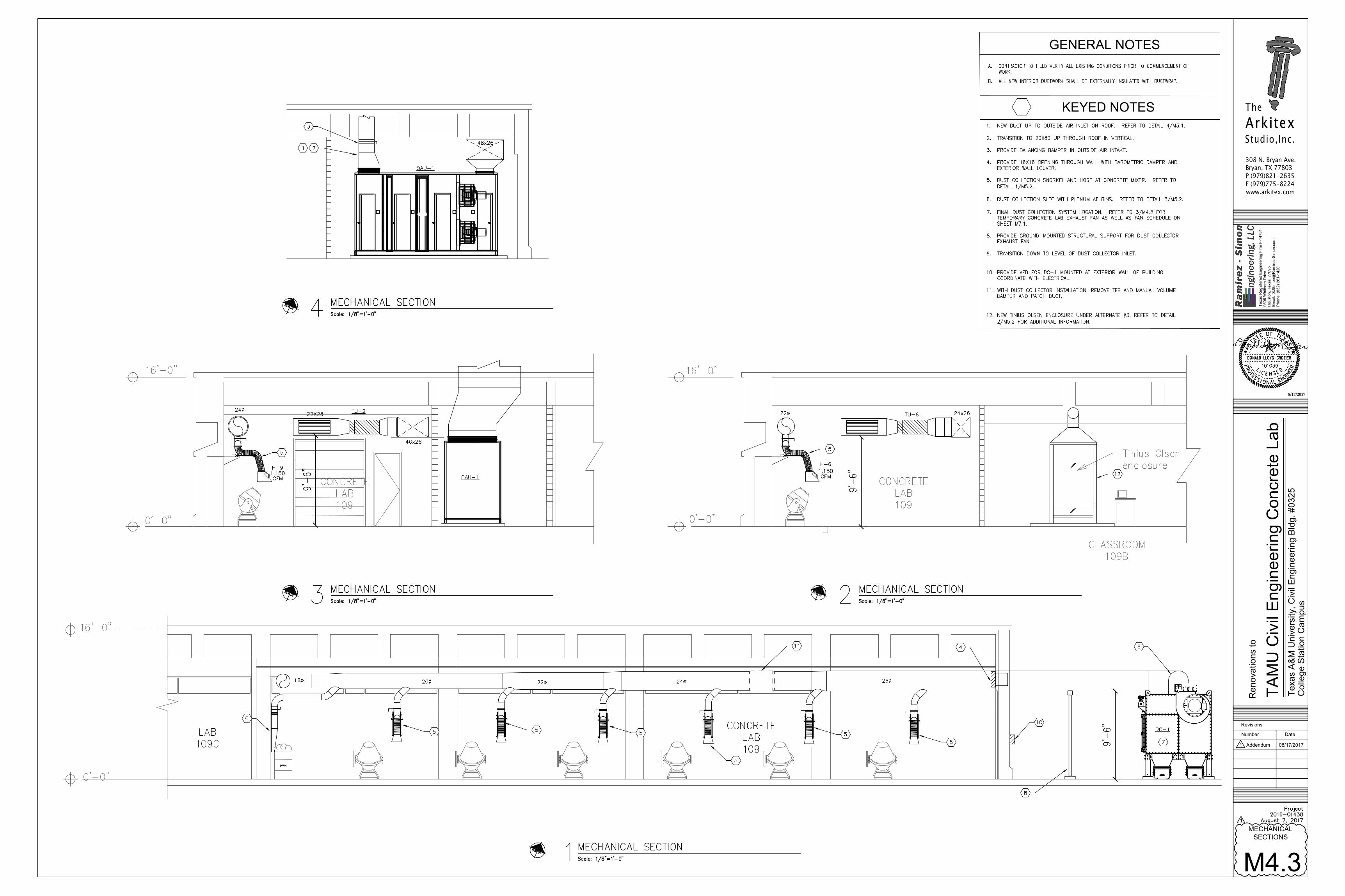
and ED1.3. c. Add Drawing Sheet number M4.3 MECHANICAL SECTIONS.
4. Section 012300 ALTERNATES: a. Revise item 3.1.G.2 as follows: “Alternate Bid: All work to prepare
existing room for the new environmental chamber, including mechanical, electrical and plumbing services, into Storage 109A. The environmental chamber is to be provided and installed by the Owner.”
5. Section 075419 POLYVINYL-CHLORIDE (PVC) ROOFING: a. Revise item 1.10.A.2 as follows: “Warranty Period: 20 years from date
of Substantial Completion.” B. Drawings:
1. Drawing G1: Add drawings M4.3 Mechancial Sections and E0.3 Electrical specifications to the Index to Drawings. Revised drawing is attached.
2. Drawing D1.1: Revised drawing is attached. a. Add General Demolition Note #7 as follows: ”Refer to Sheet A2.1 for
Alternate Bid Schedule.” b. Add General Demolition Note #8 as follows: “Remove concrete pads
and anchor bolts at removed wave tank. Grind smooth with concrete floor surface. Approximately (26) 8”x8” pads.”
c. Add General Demolition Note #9 as follows: “Remove VCT flooring from the classrooms (109B). This includes grinding floor to remove adhesive.”
d. Add General Demolition Note #10 as follows: “Remove existing classrooms seating that is bolted to the floor. This includes cutting all bolts flush with the floor and grinding smooth.”
e. Revise note to Detail 1/D1.1 to read as follows: “Sawcut and remove 24” x 24” area of concrete block for new access hatch – at existing clean-out elevation.
f. Add note to Detail 1/D1.1 to read as follows: “Remove glass panel for temporary dust evacuation duct.”
3. Drawing D1.2: Revise the size of the second floor slab opening for ductwork penetrations as shown on the attached drawing.
4. Drawing A2.1. Revised drawing is attached.
08-17-2017
308 N. Bryan Ave. Bryan, TX 77803 P (979)821-2635 F (979)775-8224 www.arkitex.com
2
a. Revise ALTERNATE BID SCHEDULE as shown. b. Revise drawing to show temporary lab exhaust location on the North
side of the existing Lab. c. Revise 2 notes in Classroom 109B to read, “Re-install salvaged
projector and projector screen.” d. Add notes to Detail 1/A2.1 as follows: “16"x16" concrete pilaster with #4
vertical reinforcement in each cell. Dowel into existing concrete block wall with #4 dowels 12" long. Space at 24" O.C. vertical, 6" embed into existing. Grout cells solid in new and existing. “
e. Add notes to Detail 1/A2.1 as follows: “Revise access door swings to open into Storage/Shop 114C and Storage 114B.”
f. Revise drawing to show Aggregate Storage roof has decreased in size to allow for Dust Collector. Structural members and base have been omitted at grid line B.
5. Drawing A2.2 Revised drawing is attached. a. Revise GENERAL NOTES, Note 13 to read as follows: Refer to 1/A2.1
for Alternate Bid Schedule. b. Add notes to Detail 1/A2.2 as follows: “Patch wall at removed pull
station.” c. Revise Detail 1/A2.2 to reflect increased size of the mechanical chase.
6. Drawing A3.1. Revised drawing is attached. a. HVAC outside air intake and notes are shown on details 1/A3.1 and
2/A3.1 b. Note has been added regarding temporary enclosure at dust
evacuation duct penetration at the window. 7. Drawing A4.1. Revised drawing is attached.
a. Revise Detail 8/A4.1 to show change in chase size. 8. Drawing Sheet A5.1. Revised drawing is attached.
a. Add note at on Detail 1, door #104 “Fixed H.M. transom above, RE 10/A5.1”
b. Add Detail 10/A5.1 INTERIOR OPENING TYPE (ALTERNATE #3) 9. Drawing Sheet A5.2. Revised drawing is attached.
a. Add Detail 18/A5.2 INTERIOR HOLLOW METAL PANEL HEAD 10. Drawing Sheet A8.1
a. Omit Detail 2/A8.1 11. Drawing S1.1, Details 1 and 6: Revise Aggregate Storage roof structure to omit
one bay. Revised drawing is attached. 12. Drawing S1.2, Detail 2. revise the size of the floor slab opening for the HVAC
chase. The revised drawing is attached. 13. Drawing S3.1, Details 1, 4, 5, 6: Revise Aggregate Storage roof structure to
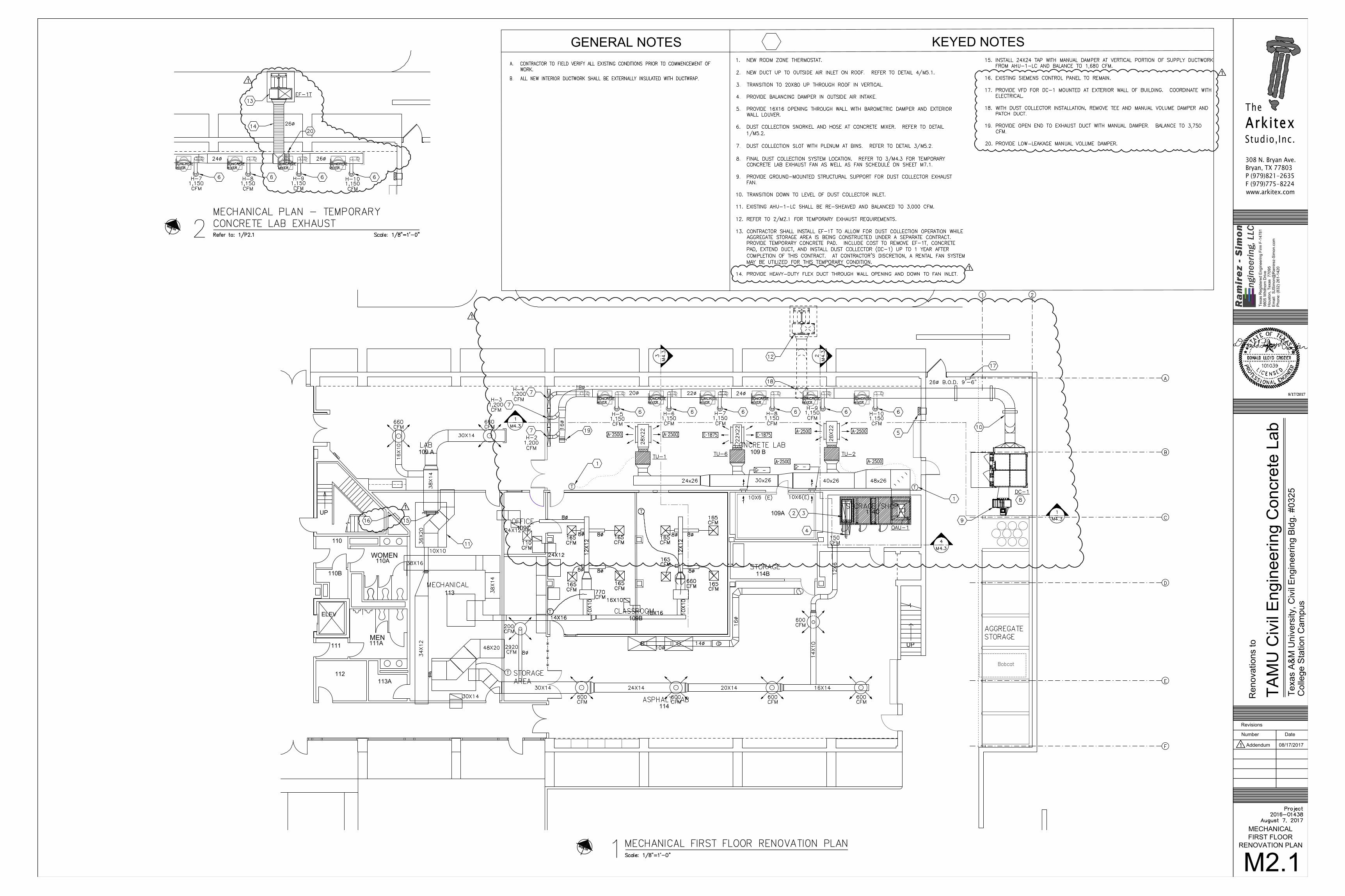
omit one bay. Revised drawing is attached 14. Drawing M2.1 – MECHANICAL FIRST FLOOR RENOVATION PLAN
a. Changed Keyed Note #14 � b. Added Keyed notes 16-20. � c. Added Terminal Unit TU-6 to base bid package. � d. Changed Air Devices ‘A’ and associated ductwork in Room 109B � e. Added open end and manual damper to end of Dust Collection exhaust
duct run. � f. Tagged Type ‘G’ grilles. � g. Moved temporary exhaust fan EF-1T. �
15. Drawing �M2.2 – MECHANICAL SECOND FLOOR RENOVATION PLAN a. Changed Keyed note #1 b. Changed direction of OA Intake gooseneck.
16. Drawing M3.1 – MECHANICAL FIRST FLOOR PIPING PLAN a. Added Terminal Unit TU-6 to base bid package. � b. Changed size of branch piping to TU-1 and TU-2 � c. Added Keyed note #6 �
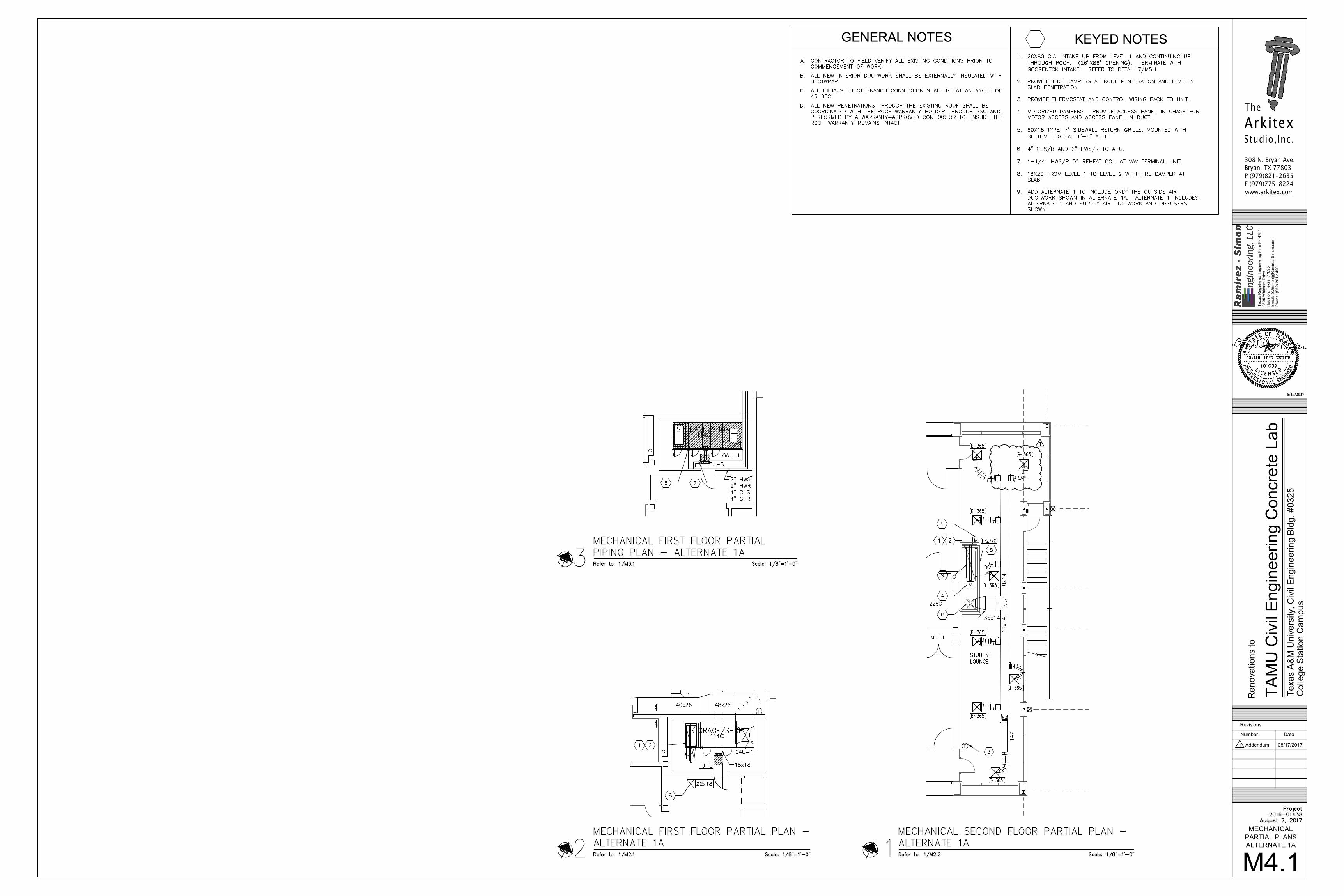
17. Drawing �M4.1 – MECHANICAL PARTIAL PLANS – ALTERNATE 1A
3
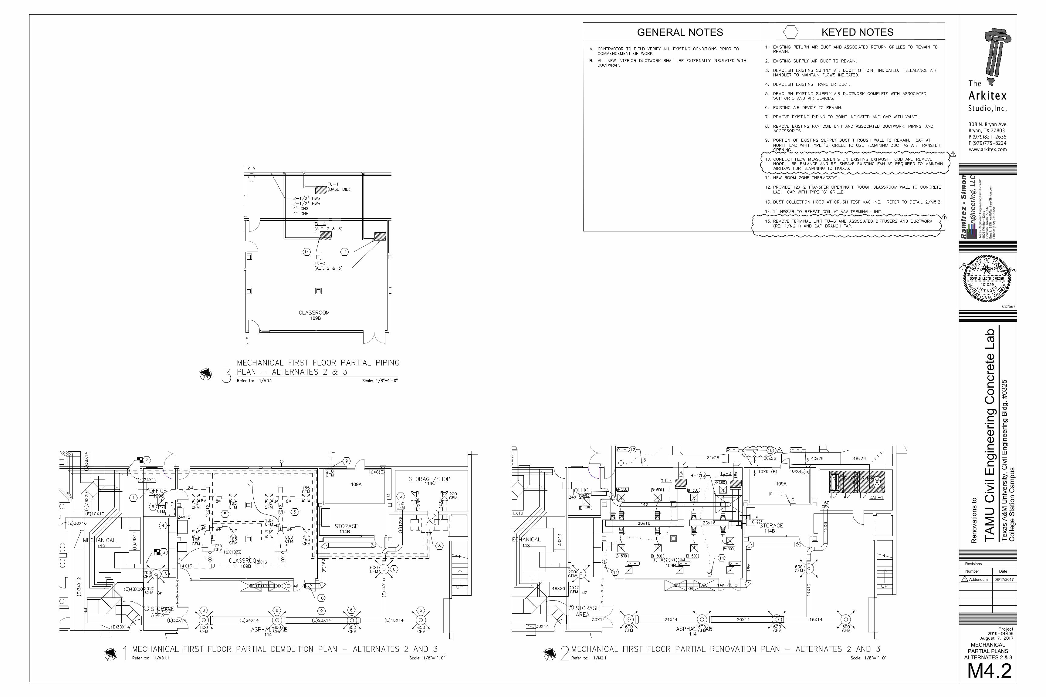
a. Changed SA duct routing in 1/M4.1 18. Drawing �M4.2 – MECHANICAL PARTIAL PLANS – ALTERNATES 2 & 3
a. Changed Keyed Note #10 b. Added Keyed Note #15 � c. Added removal of Terminal Unit TU-6 to scope of Alternates 2 & 3 �
19. Drawing �M4.3 – MECHANICAL SECTIONS a. Added sheet M4.3
20. Drawing T�M5.2 – MECHANICAL DETAILS a. Changed Exhaust Plenum dimension in detail 3/M5.2
21. Drawing �M5.3 – MECHANICAL DETAILS a. Changed detail 1/M5.3 b. Added detail 4/M5.3
22. Drawing M6.1 – MECHANICAL CONTROLS a. Corrected detail titles for 1/M6.1 and 3/M6.1 � b. Changed detail 2/M6.1. �
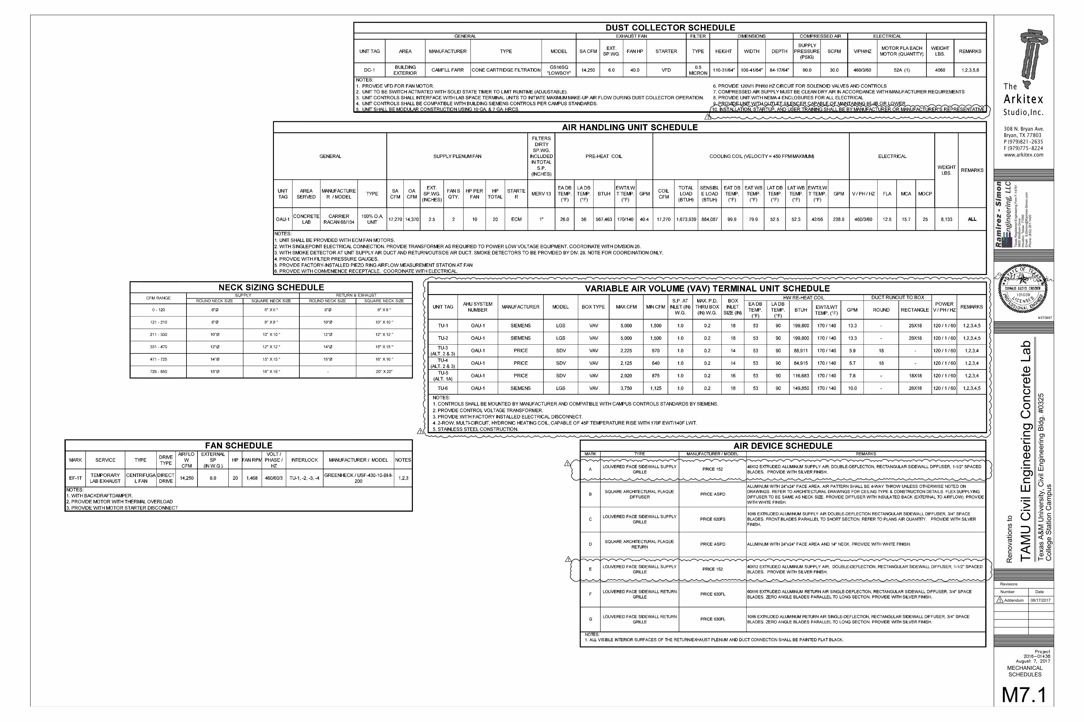
23. Drawing M5.3 – MECHANICAL SCHEDULES a. Added note #10 to Dust Collector Schedule � b. Deleted HW Re-Heat Coil section from Air Handling Unit Schedule � c. Added TU-6 to VAV Terminal Unit Schedule � d. Added Note #5 to VAV Terminal Unit Schedule � e. Changed manufacturer and model info for TU-1 and TU-2 on VAV
Terminal Unit Schedule � f. Added HW Re-heat coil info toe VAV Terminal Unit Schedule � g. Changed Air Device Types ‘A’ and ‘E’ on Air Device Schedule. �
24. Drawing �E0.2 – ELECTRICAL SPECIFICATIONS (Division 28 Fire Alarm) a. Update sheet number to E0.3.
25. Drawing �ED1.1 – LIGHTING DEMOLITION FIRST FLOOR PLAN a. Clarify keyed note.
26. Drawing �ED1.2 – ELECTRICAL DEMOLITION FIRST FLOOR PLAN a. Revise call out of “Fan Coil Unit” to “Terminal Unit”
27. Drawing E1.1 – LIGHTING FIRST FLOOR RENOVATION PLAN a. Provide an additional wall switch in Classroom 109B near southwest
door. � b. Provide clarification on a few keyed note call outs. � c. Provide weatherproof cover on light switches in Concrete Lab 109. �
28. Drawing E1.2 – LIGHT SECOND FLOOR RENOVATION PLAN a. Provide notes on sheet to indicate that ceilings in adjoining spaces to
the project area are not accessible. � b. Relocate lighting dimmer controller and emergency control unit to avoid
conflict with new mechanical chase. � 29. Drawing E2.1 – ELECTRICAL FIRST FLOOR RENOVATION PLAN
a. Revise electrical service to EF-1T and DC-1. � b. Include TU-6 to base bid and remove TU-6 from scope under Additive
Alternate #2. � 30. Drawing E2.2 – ELECTRICAL SECOND FLOOR RENOVATION PLAN
a. Provide notes on sheet to indicate that ceilings in adjoining spaces to the project area are not accessible.
31. Drawing �E6.1 – ELECTRICAL ONE LINE DIAGRAM a. Revise electrical service to EF-1T and DC-1.
32. Drawing E7.1 – ELECTRICAL SCHEDULES a. Updated Panel 1LF to indicate panel must have a NEMA 12 enclosure
rating. b. Update wall pack light fixture W27 lumen output. �
33. Drawing P0.3 SPECIFICATIONS was omitted from the printing. It is attached. 34. Drawing �PD1.1 – PLUMBING FIRST FLOOR DEMOLITION PLAN
a. Changed Keyed Note #3
4
b. Changed Keyed Note #7 � c. Added 1-1/2” DCW line to be re-routed � d. Moved demo of piping to demolished exhaust hood to scope of
Alternate #2 � 35. Drawing �P2.1 – PLUMBING FIRST FLOOR RENOVATION PLAN
a. Added Keyed Note #11 b. Changed Fire Protection Notes ‘D’ & ‘I’ � c. Added 1-1/2” DCW line to be re-routed to Emergency Eye
Wash/Shower � d. Added Emergency Eye Wash/Shower EES-1
36. Drawing P4.1 – PLUMBING PARTIAL PLANS – ALTERNATES 1, 1A, & 2 a. Changed Keyed Notes #1, #3, #6 � b. Added Keyed Notes #7, #8, #9, and #10 � c. Changed Fire Protection Notes ‘D’ & ‘I’ � d. Changed Routing of new Roof Drains for Alternates #1 and #1A as
shown in 1/P4.1 and 3/P4.1 � e. Moved demo of piping to demolished exhaust hood to scope of
Alternate #2 in 4/P4.1 � f. Changed extent of lab gas, vacuum, water, and compressed air piping
demolition shown in �4/P4.1 � 37. Drawing �P4.2 – PLUMBING PARTIAL PLANS – ALTERNATES 3 & 5
a. Changed Fire Protection Notes ‘D’ & ‘I’ 38. Drawing P5.1
a. Added Emergency Eye Wash/Shower EES-1 to Plumbing Fixture Schedule �
b. Changed detail 1/P5.1 and Detail 2/P5.1. � END OF ADDENDUM 1

308 N. Bryan Ave. Bryan, TX 77803 P (979)821-2635 F (979)775-8224 www.arkitex.com
Revisions
Number Date
The
Arkitex Studio, Inc.
Project 17020 August 7, 2017
Reno
vatio
n to
TAM
U C
ivil
Engi
neer
ing
Conc
rete
Lab
Texa
s A
&M
Uni
vers
ity, C
ivil
Engi
neer
ing
Bldg
. #03
25 -
Colle
ge S
tatio
n Ca
mpu
s
8/17/17
INDEX TO DRAWINGSNo scaleRefer to: all drawings1ABBREVIATIONS
No scaleRefer to: all drawings4
00 Cover sheet GENERAL G1 General information DEMOLITION D1.1 First Floor Demo Plan D1.2 Second Floor Demo Plan ARCHITECTURAL A2.1 First Floor Plan, Aggregate Storage Plan A2.2 Second Floor Plan A3.1 Building Elevations A4.1 Details A5.1 Schedules A5.2 Details A6.1 Wall Sections A6.2 Wall Sections/Details A8.1 First Floor RCP A8.2 Second Floor RCP A9.1 Roof Plan STRUCTURAL S1.1 Foundation Plan and Details S1.2 Foundation Plan and Details S3.1 Framing Pan and Details S3.2 Framing Plan and Details S3.3 Framing Details MECHANICAL M0.0 Mechanical symbols, abbrev and general notes MD1.1 Mechanical first floor demolition plan M2.1 Mechanical first floor renovation plan M2.2 Mechanical second floor renovation plan M3.1 Mechanical first floor piping plan M4.1 Mechanical partial plans - Alternate 1A M4.2 Mechanical partial plans - Alternates 2 and 3 M4.3 Mechanical Sections M5.1 Mechanical details M5.2 Mechanical details M5.3 Mechanical details M5.4 Mechanical details M6.1 Mechanical controls M6.2 Mechanical controls M7.1 Mechanical schedules
Q.T.QTR.
Quarry tileQuarter
V.B.V.C.T.
VERT.VEST.V.I.F.V.W.C.
Venetian blindVinyl composition tile
VerticalVestibuleVerify in FieldVinyl wall covering
W.W/W.C.WD.
WestWithWater closetWood
PT.PTD.P.V.C.PVMT.
PART.PBD.P.C.C.PL.P.LAM.PLAS.PLYWD.PNL.POL.PR.
P.S.F.P.S.I.
PRE-FIN.
PointPaintedPolyvinyl chloridePavement
PartitionParticle boardPre-cast concretePlatePlastic laminatePlasterPlywoodPanel(-ing)PolishPair
Pounds per square footPounds per square inch
Pre-finish(-ed)
R.R/ARAD.R.D.
REF.REFG.REINF.REQD.RESIL.REV.RM.R.O.
RECEPT.
Riser(s)Return airRadiusRoof drain
ReferenceRefrigeratorReinforce(-d,-ing)Require(-d)ResilientReviseRoomRough opening
Reception
S.S/ASAN.S.C.SCHED.S.D.SECT.SHWR.SHT.SIM.SL.SPEC.
SQ.S.SK.S.ST.STA.STD.STL.STOR.
SURF.SUSP.
SYM.SYS.
STRUCT.
SPEC'D.
SVC.
SouthSupply airSanitarySolid coreScheduleSoap dispenserSectionShowerSheetSimilarSlopeSpecification(-s)SpecifiedSquareService sinkStainless steelStationStandard, stainedSteelStorage
SurfaceSuspended
SymmetricalSystem
Structure(-al)
Service
Angle
Channel
Center line
Diameter or round
Perpendicular
Pound or number
And
#
&
CL
ClosetClearConcrete masonry unitColumnConcreteConditionConstruction(-ed)ContinuousCorporationCorrugatedCarpetCurtain rodCountersinkCeramic tileCubic feet (foot)
Cubic inch (es)
Catch basinCementCeramicCounter flashingCubic feet per minute
Cabinet
Corner guardCoat hookCast ironControl jointCeiling
Cubic yard (es)
CLO.CLR.C.M.U.COL.CONC.COND.CONST.CONT.CORP.CORR.CPT.C.R.CS.C.T.CU. FT.
CU. IN.CU. YD.
CAB.C.B.CEM.CER.C.FLASH.C.F.M.C.G.C.H.C.I.C.J.CLG.
Anchor BoltAboveAir conditioningAcousticalArea drainAddendum
Above finished floorAggregateAir handling unitAllowanceAlternateAluminumAnodizedApproximate(ly)Architect(-ural)AsphaltAutomaticAuxiliaryAverage
Additional
APPROX.
A.B.ABV.A/CACOUS.A.D.ADD.
A.F.F.AGG.A.H.U.ALLOW.ALT.ALUM.ANOD.
ARCH.ASPH.AUTO.AUX.AVG.
ADD'L.
EastEachExpansion bolt
Electric water cooler
Electric hand dryer
ElevationElectric (-al)EmergencyEnclosureEqualExhaust
ExpansionExterior
Expansion joint
Existing
E.EA.E.B.
E.W.C.
E.H.D.
ELEV.ELEC.EMER.ENCL.EQ.EXH.
EXP.EXT.
E.J.
EXIST.
I.D.IN.INCL.INSUL.INT.INV.
Inside dimensionInchInclude(-ing)InsulationInteriorInvert
JAN.JST.JT.
JanitorJoistJoint
LAM.
LAV.LB.LKR.L.L.H.L.L.V.
L.PT.LT.LTL.LVL.LVR.
Laminate(-d)
LavatoryPoundLockerLong leg horizontalLong leg vertical
Low pointLightLintelLevelLouver
FAB.F.A.F.D.FDN.F.E.F.E.C.
F.H.C.F.H.R.F.HYD.FIN.F.L.FLASH.FLEX.FLR.FLUOR.FT.FTG.FURR.FUT.F.W.C.
Fabric (-ate, -ated)Fire alarmFloor drainFoundationFire extinguisherFire extinguisher cabinet
Fire hose cabinetFire hose rackFire hydrantFinish(-ed)Flow lineFlashingFlexibleFloorFluorescentFoot (Feet)FootingFurredFutureFabric wall covering
GA.GALV.G.B.G.C.G.I.GL.GR.GYP.
GaugeGalvanize(-d)Grab barGeneral contractorGalvanized ironGlass, glaze(-d,-ing)GradeGypsum
HDWD.HDWR.H.M.HORIZ.H. PT.HR.HT.HTG.HVAC
H.H.B.H.C.
HardwoodHardwareHollow metalHorizontalHigh pointHourHeightHeatingHeating, ventilation and air conditioning
HighHose bibHandicapped
MATL.MAX.
M.B.MAS.
M.C.MECH.
MED.
MTL.
MEZZ.MFR.M.H.MIN.MIR.MISC.MLDG.M.O.MTD.
MTG.MULL.
MEMB.
MaterialMaximum
Machine boltMasonry
Medicine cabinetMechanical
Medium
Metal
MezzanineManufacturerManholeMinimumMirrorMiscellaneousMouldingMasonry openingMounted
MountingMullion
Membrane
N.N.I.C.NO.NOM.N.T.S.
NorthNot in contractNumberNominalNot to scale
OH.
O.A.O/AO.C.O.D.OFF.
OPNG.OPP.OZ.
Overhead
OverallOutside airOn centerOutside diameterOffice
OpeningOpposite (hand)Ounce
BoardBuildingBlockBlockingBeamBench mark
BottomBasement
BD.BLDG.BLK.BLKG.BM.B.M.
BOTT.BSMT.
Built-up roofingB.U.R.
By othersBO
DoubleDetailDrinking fountainDouble hungDiagonalDiameterDimensionDivisionDownDoor opening
DoorDishwasherDowelDownspoutDrawing (-s)Drawer
DBL.DET.D.F.D.H.DIAG.DIAM.DIM.DIV.DN.D.O.
DR.D.W.DWL.D.S.DWG.DWR.
DampproofingDP
T.T.B.T.C.T.D.T.D.R.TEL.TEMP.T>HK.THRES.T.P.
T.SL.T.O.S.T.T.D.TYP.
TreadTowel barTop of curbTowel dispenserTowel dispenser receptacleTelephoneTemperedTongue and grooveThick(-ness)ThresholdTop of pavement
Top of slabTop of steelToilet tissue dispenserTypical
TRTD Treated
U.N.O. Unless noted otherwiseUR. Urinal
GRAPHIC SYMBOLSNo scaleRefer to: all drawings2
MATERIAL SYMBOLSNo scaleRefer to: all drawings3
Rigid insulation
Glass - large scale
Glass - small scale
Insulation
Acoustical tile or board
Plaster on metal lath
Metal - large scale
Plywood
Finish wood
Dimensional lumber - continuous
Dimensional lumber - blocking
Gypsum board
Earth
Concrete
Brick
Concrete masonry units
Stone
Mortar, grout, sand
1 of 1
G1
N
Plan North
North arrow
Elevation
Wall section
Building section
Partition type
Door number
Window type
Finish type, alternate window type
Column line reference
Center line
Hidden line
4 / A3.1
4 / A3.1
4 / A3.1
Detail reference
Interior elevation
Break lineB
B
Section detail4 / A3.1
R.9
Keynote, toilet accessory2323
AA
138 A
138 A
WW
1
Elevation marker
Elevation marker325.00'
Top of parapet± 125'-3 1/2" (V.I.F.)
66Revision number
4 / A3.1
4 / A
3.1
4 / A3.1
4 / A
3.1
4 / A
3.1
4 / A3.1
4 / A
3.1
15B A4.1
VICINITY MAPNo scaleRefer to: all drawings5
TAMU Civil Engineering Concrete Lab Building #325
SSC
No.
201
6-01
438
KEY PLAN - FLOOR 1Scale: 1" = 40'-0"Refer to: all drawings7
Lab renovation. Refer to 1/A2.1
KEY PLAN - FLOOR 2Scale: 1" = 40'-0"Refer to: all drawings8
(ALTERNATE BID #1) Balcony enclosure. Refer to 1/A2.2
CODE REVIEW6
Existing building code review: 1982 Southern Building Code and 1981 NFPA 101 Lab building classified as B business and Type II construction First floor sprinklered. First floor area 19,948 gross, 16,509 net Second floor area 18,100 gross, 14,922 net Existing stairs are 4'-6” wide. Current Code 2015 IBC and 2015 NFPA 101 Occupant load at Concrete Lab = 1780 sf gross, 1178 sf net at 50 sf net/occ = 24 occupants Ocupant load at Classroom = 1172 sf at 30sf/occ = 40 occupants
(half to north and half to south = 20 each direction) Total load in Concrete Lab = 24 plus 20 = 44 occupants = 1 exit required. Second floor load: 4 Labs = 3469 sf at 30 sf/occ = 116 occupants
(half exit down the exterior stairs = 58) Study Lounge = 1058 sf at 30 sf/occ = 36 Total load at Second Floor = 36 + 58 = 94 occupants exiting down exterior stairs. 0.3” width per occupant = 28.2” of stair width required.
ELECTRICAL E0.0 Electrical legend and general notes E0.1 Electrical specifications E0.2 Electrical specifications E0.3 Electrical specifications EE2.1 Lighting first floor demolition plan ED2.2 Electrical first floor demolition plan ED2.3 Electrical second floor demolition plan E1.1 Lighting first floor renovation plan E1.2 LIghting second floor renovation plan E2.1 Electrical first floor renovation plan E2.2 Electrical second floor renovation plan E5.1 Electrical details E6.1 Electrical one line diagram E7.1 Electrical schedules E7.2 Electrical schedules PLUMBING P0.0 Plumbing symbols, abbreviations and general notes P0.1 Plumbing specifications PD1.1 Plumbing demolition plan P2.1 Plumbing first floor renovation plan P4.1 Plumbing partial plans - Alternates 1, 1A, and 2 P4.2 Plumbing partial plans - Alternates 3 and 5 P5.1 Plumbing details & schedules
Refer to: all drawings No scale
1
1 Addendum 08/17/2017
1

308 N. Bryan Ave. Bryan, TX 77803 P (979)821-2635 F (979)775-8224 www.arkitex.com
Reno
vatio
n fo
r
TAM
U C
ivil
Engi
neer
ing
Conc
rete
Lab
Revisions
Number Date
The
Arkitex Studio, Inc.
Project 17020 August 7, 2017
Texa
s A
&M
Uni
vers
ity, C
ivil
Engi
neer
ing
Bldg
. #03
25 -
Colle
ge S
tatio
n Ca
mpu
s
SSC
No.
201
6 - 0
1438
8/17/17
xx
x
110B
110
111
112 113A
110A
111A
WOMEN
MEN
ELEV
STORAGE AREA
109A
114B
114C
109
114
109C
109B
ASPHALT LAB
CONCRETE LAB
STORAGE
STORAGE
STORAGE/SHOP
OFFICE
CLASSROOM
MECHANICAL
LAB
EXISTING BUILDING
UP
UP
113
109 A
STAIR
CORRIDOR
CORRIDOR
(NIC)
(NIC)
(NIC)(NIC)
(NIC)
(NIC)
(NIC)
(NIC)
(NIC)
(NIC)
(NIC)
FIRST FLOOR REFLECTED CEILING PLANScale: 1/8"=1'-0"1NORTH
Plan North A8.10' 5' 10' 20'
Flush mounted fixture 2'x4'
Exit Light
LEGEND
Exposed structure
2x2 Ceiling Tile
Return air
Supply diffuser
12'-0" AFF
11'-4" AFF
Tinius Olsen dust collecting hood duct
GENERAL NOTES
1.
2.
3.
4.
Refer to electrical drawings for lighting fixture schedule. Existing exterior lighting to remain unchanged unless noted otherwise on plan. Patch and repair floor, walls, and ceiling materials at locations where items or portions of building are removed; typical. Note: Not all exit lighting is shown on Reflected Ceiling Plan, refer to Electrical for lighting schedule.
5.
6. 7.
8.
Building is fully sprinklered to meet the State of Texas fire protection standards. Sprinkler contractor shall submit layout drawing to architect and Owner for review prior to commencing work. Refer to sheet 4/A5.1 for finish schedule. Refer to Mechanical and Electrical drawinsg for light fixture and grille schedules. Center celing tile or grid in room as shown. Unless noted otherwise, center elements in ceiling tiles.
Refer to 1/A2.1
10 of 12
Utility wall mounted fixture
Reinstall projectors
Supports for electrical extension cord reels. Refer to 2/A8.1. Typical of 8; verify locations with Owner.
EXTENSION REEL SUPPORT DETAILScale: 1 1/2"=1'-0"2 Refer to 1/A8.1
1
1 Addendum 08/17/2017
110B
109A
114B
114C
109 B
114
109C
113
110
111
112113A
110A
111A
109B
109 A
WOMEN
MEN
ELEV
UP
UP
T
M2.1
MECHANICALFIRST FLOOR
RENOVATION PLAN
Texas R
egis
tere
d E
ngin
eering F
irm
F-1
4781
9805 W
hithorn
Drive
Housto
n, T
exas 77095
Em
ail:
S
JS
imon@
Ram
irez-S
imon.c
om
Phone: (8
32)
261-1
420
8/17/2017
308 N. Bryan Ave.Bryan, TX 77803P (979)821-2635F (979)775-8224www.arkitex.com
Re
no
va
tio
ns t
o
TA
MU
Civ
il E
ngin
eering C
oncre
te L
ab
Te
xa
s A
&M
Un
ive
rsity,
Civ
il E
ng
ine
erin
g B
ldg
. #
03
25
Revisions
Number Date
TheArkitexStudio,Inc.
Co
lleg
e S
tatio
n C
am
pu
s
GENERAL NOTES KEYED NOTES
Addendum 08/17/2017

UP
GENERAL NOTES KEYED NOTES
Texa
s R
egis
tere
d E
ngin
eerin
g Fi
rm F
-147
8198
05 W
hith
orn
Driv
eH
oust
on, T
exas
770
95E
mai
l: S
JSim
on@
Ram
irez-
Sim
on.c
omP
hone
: (83
2) 2
61-1
420
8/17/2017
308 N. Bryan Ave.Bryan, TX 77803P (979)821-2635F (979)775-8224www.arkitex.com
Ren
ovat
ions
to
TAM
U C
ivil
Eng
inee
ring
Con
cret
e La
bTe
xas
A&
M U
nive
rsity
, Civ
il E
ngin
eerin
g B
ldg.
#03
25
Revisions
Number Date
TheArkitexStudio,Inc.
Col
lege
Sta
tion
Cam
pus
M2.2MECHANICAL
SECOND FLOORRENOVATION PLAN
Addendum 08/17/2017

110B
109A
114B
114C
109 B
114
109C
113
110
111
112113A
110A
111A
109B
109 A
WOMEN
MEN
ELEV
UP
UP
M3.1MECHANICAL
FIRST FLOOR PIPINGPLAN
Texa
s R
egis
tere
d E
ngin
eerin
g Fi
rm F
-147
8198
05 W
hith
orn
Driv
eH
oust
on, T
exas
770
95E
mai
l: S
JSim
on@
Ram
irez-
Sim
on.c
omP
hone
: (83
2) 2
61-1
420
8/17/2017
308 N. Bryan Ave.Bryan, TX 77803P (979)821-2635F (979)775-8224www.arkitex.com
Ren
ovat
ions
to
TAM
U C
ivil
Eng
inee
ring
Con
cret
e La
bTe
xas
A&
M U
nive
rsity
, Civ
il E
ngin
eerin
g B
ldg.
#03
25
Revisions
Number Date
TheArkitexStudio,Inc.
Col
lege
Sta
tion
Cam
pus
GENERAL NOTES KEYED NOTES
Addendum 08/17/2017
T
GENERAL NOTES KEYED NOTES
114C
T
114C
114C
Texas R
egis
tered E
ngin
eerin
g F
irm
F-14781
9805 W
hithorn D
riv
e
Housto
n, T
exas 77095
Em
ail: S
JS
imon@
Ram
irez-S
imon.c
om
Phone: (832) 2
61-1420
8/17/2017
308 N. Bryan Ave.Bryan, TX 77803P (979)821-2635F (979)775-8224www.arkitex.com
Re
no
va
tio
ns t
o
TA
MU
Civ
il E
ngin
eerin
g C
oncrete
Lab
Te
xa
s A
&M
Un
ive
rsity,
Civ
il E
ng
ine
erin
g B
ldg
. #
03
25
Revisions
Number Date
TheArkitexStudio,Inc.
Co
lle
ge
Sta
tio
n C
am
pu
s
M4.1
MECHANICAL
PARTIAL PLANS
ALTERNATE 1A
Addendum 08/17/2017
109A
114B
114C
114
109C
113
109B
WOMEN
UP
109A
114B
114C
114
109C
113
109B
UP
T
T
109B
M4.2
MECHANICALPARTIAL PLANS
ALTERNATES 2 & 3
Texas R
egis
tere
d E
ngin
eering F
irm
F-1
4781
9805 W
hithorn
Drive
Housto
n, T
exas 77095
Em
ail:
S
JS
imon@
Ram
irez-S
imon.c
om
Phone: (8
32)
261-1
420
8/17/2017
308 N. Bryan Ave.Bryan, TX 77803P (979)821-2635F (979)775-8224www.arkitex.com
Re
no
va
tio
ns t
o
TA
MU
Civ
il E
ngin
eering C
oncre
te L
ab
Te
xa
s A
&M
Un
ive
rsity,
Civ
il E
ng
ine
erin
g B
ldg
. #
03
25
Revisions
Number Date
TheArkitexStudio,Inc.
Co
lleg
e S
tatio
n C
am
pu
s
GENERAL NOTES KEYED NOTES
Addendum 08/17/2017
M4.3
MECHANICALSECTIONS
Texa
s R
egis
tere
d E
ngin
eering F
irm
F-1
4781
9805 W
hith
orn
Drive
Houst
on, T
exa
s 7
7095
Em
ail:
S
JSim
on@
Ram
irez-
Sim
on.c
om
Phone: (8
32)
261-1
420
8/17/2017
308 N. Bryan Ave.Bryan, TX 77803P (979)821-2635F (979)775-8224www.arkitex.com
Re
no
vatio
ns
to
TA
MU
Civ
il E
ngin
eering C
oncr
ete
Lab
Te
xas
A&
M U
niv
ers
ity,
Civ
il E
ng
ine
erin
g B
ldg
. #
03
25
Revisions
Number Date
TheArkitexStudio,Inc.
Co
lleg
e S
tatio
n C
am
pu
s
GENERAL NOTES
KEYED NOTES
Addendum 08/17/2017

SCALE: N.T.S.
SLOT PLENUM DETAIL3
SCALE: N.T.S.
CANOPY ENCLOSURE FOR TINIUS OLSEN MACHINE DETAIL2
SCALE: N.T.S.
EXTRACTION ARMS FOR CONCRETE MIXERS DETAIL1
SCALE: N.T.S.
CONDENSATE DRAIN PIPING 5
SCALE: N.T.S.
GRILLE CONNECTION DETAIL 6
UNISTRUT
HANGER RODTHREADED STEEL3/8" DIAMETER ALL
TRAPEZE OR P-30001-1/2" x 1-1/2' x 1/8" ANGLE
DUCT
SCALE: N.T.S.
DUCT SUPPORT DETAIL7
SCALE: N.T.S.
DUCT BRANCH TAKE OFF 9
SCALE: N.T.S.
DUCT PENETRATION THROUGH ROOF4
SCALE: N.T.S.
ROUND DUCT HANGER8
Texa
s R
egis
tere
d E
ngin
eerin
g Fi
rm F
-147
8198
05 W
hith
orn
Driv
eH
oust
on, T
exas
770
95E
mai
l: S
JSim
on@
Ram
irez-
Sim
on.c
omP
hone
: (83
2) 2
61-1
420
8/17/2017
308 N. Bryan Ave.Bryan, TX 77803P (979)821-2635F (979)775-8224www.arkitex.com
Ren
ovat
ions
to
TAM
U C
ivil
Eng
inee
ring
Con
cret
e La
bTe
xas
A&
M U
nive
rsity
, Civ
il E
ngin
eerin
g B
ldg.
#03
25
Revisions
Number Date
TheArkitexStudio,Inc.
Col
lege
Sta
tion
Cam
pus
M5.2MECHANICAL
DETAILS
Addendum 08/17/2017

REFER TOSPECIFICATIONSFOR DUCTWORK
BOLT BAND TOUNISTRUT CHANNEL ONBOTH SIDES
SCALE: N.T.S.
DUCT SUPPORT ON EXTERIOR GRADE DETAIL1
MINIMUM 6'-8" ABOVEFINISHED GRADE
EXHAUST DUCT 1" GALVANIZED STEEL BANDAROUND DUCTWORK
DUCT GALVANIZEDSTEEL SADDLE
SCALE: N.T.S.2
4" X 12 GAUGE 4-BOLTCORNER BRACKET IN12 GAUGE UNISTRUT(TYPICAL)
TO ROOF DETAILWIND LOADING BASE SUPPORT INSTALLATION
GALVANIZED UNISTRUT.COORDINATE SIZE WITHDUCT SUPPORTMANUFACTURER
190"
72"
SCALE: N.T.S.
AIR HANDLING UNIT DETAIL
1. THIS DETAIL SHOWS GENERAL ARRANGEMENT OF A/C UNIT COMPONENTS ONLY.2. COIL CONNECTION SIDE LOCATIONS AND ACCESS DOOR SWING LOCATIONS SHALL BE COORDINATED WITH PROJECT
SPECIFIC CONDITIONS.3. CONDENSATE SHALL DISCHARGE TO APPROVED PLUMBING FIXTURE INSIDE OF BUILDING. CONDENSATE DRAIN SHALL
SLOPE TOWARDS DRAIN.4. ALL ACCESS DOOR SHALL BE 18" MINIMUM WIDTH PER TAMU STANDARDS.
N O T E S:
3
SD
SADUCT MOUNTED SMOKE DETECTOR
(ONLY FOR UNITS 2000 CFM OR ABOVE)
OA
TRANSITION ASREQUIRED
DUCT MOUNTED SMOKEDETECTOR
SD
PLAN VIEW
ELEVATION VIEW
MIX AIR DAMPER
FILT
ER
S S
EC
TIO
N
PLE
NU
M F
AN
S
INTA
KE
PLE
NU
M S
EC
TIO
N
AC
CE
SS
SE
CTI
ON
CO
OLI
NG
CO
IL S
EC
TIO
N
HE
ATI
NG
CO
IL S
EC
TIO
N
AC
CE
SS
SE
CTI
ON
REFER TO PLAN FORCONDENSATE DRAIN ROUTING
TRANSITION ASREQUIRED
SCALE: N.T.S.
CONCRETE LAB SUPPLY AIR VALVE DETAIL4
Texa
s R
egis
tere
d E
ngin
eerin
g Fi
rm F
-147
8198
05 W
hith
orn
Driv
eH
oust
on, T
exas
770
95E
mai
l: S
JSim
on@
Ram
irez-
Sim
on.c
omP
hone
: (83
2) 2
61-1
420
8/17/2017
308 N. Bryan Ave.Bryan, TX 77803P (979)821-2635F (979)775-8224www.arkitex.com
Ren
ovat
ions
to
TAM
U C
ivil
Eng
inee
ring
Con
cret
e La
bTe
xas
A&
M U
nive
rsity
, Civ
il E
ngin
eerin
g B
ldg.
#03
25
Revisions
Number Date
TheArkitexStudio,Inc.
Col
lege
Sta
tion
Cam
pus
M5.3MECHANICAL
DETAILS
Addendum 08/17/2017

LA
AT
LS
LE
LITLIC
LCVLC
VA
XV
YS
VS
YCD
INSTRUMENTATION ABBREVIATION LIST
AIC
AETAC
AEAA
CODE CODE
KC
CODE
YIYA
ZIZS
ZC
LEVEL ALARM
ANALYTICAL TRANSMITTER
PRESSURE DIFFERENTIAL TRANSMITTER
LEVEL SWITCH
LEVEL ELEMENT
LEVEL INDICATING TRANSMITTERLEVEL INDICATING CONTROLLER
LEVEL CONTROL VALVELEVEL CONTROLLER (STAND ALONE)
VIBRATION ALARM
SOLENOID VALVE
SMOKE DETECTOR
VIBRATION SWITCH
SMOKE DAMPER
TEMPERATURE INDICATING CONTROLLERTEMPERATURE INDICATING TRANSMITTER
TEMPERATURE ELEMENT TRANSMITTER
ANALYTICAL INDICATING CONTROLLER
ANALYTICAL ELEMENT TRANSMITTERANALYTICAL CONTROLLER
ANALYTICAL ELEMENTANALYTICAL ALARMDESCRIPTION DESCRIPTION
CLOCK
DESCRIPTION
EQUIPMENT STATUSEQUIPMENT ALARM
POSITION INDICATORPOSITION SWITCH
POSITION CONTROL
NC NORMALLY CLOSED
NO NORMALLY OPEN
I UNDEFINED INTERLOCK LOGIC
FIELDMOUNTED MOUNTED
PANEL AUXILIARYLOCATION
ACCESSIBLE INACCESSIBLELOCATIONAUXILIARY
DISCRETE INSTRUMENTS
SHARED DISPLAY, SHARED CONTROL
PROGRAMMABLE LOGIC CONTROLOR DIRECT DIGITAL CONTROL
DUCT MOUNTEDAVERAGING
ELEMENT/SENSOR ELEMENT/SENSOR
DIFFERENTIAL PRESSUREELEMENT/SENSOR
FLOW ARROWXXX INDICATES AIR TYPE
INSTRUMENT NAMING CONVENTION
XXX - FUNCTION IDNNN - DEVICE NUMBER
LINE TYPE LEGEND
INTERNAL SYSTEM LINK
ELECTRICAL SIGNAL
PNEUMATIC SIGNAL
NNNXXX
TE
~ ~
~ ~
PD
TE
GENERAL INSTRUMENT SYMBOLS
TEMPERATURE
NOTE: CONTROLS SHALL BE SIEMENS. ALL POINTS SHALL COMMUNICATE WITH TAMU UES MAIN BAS.
AI ANALOG INPUTAO ANALOG OUTPUT
DI DISCRETE INPUTDO DISCRETE OUTPUT
N.T.S2
SEQUENCE OF OPERATIONS
~ CONTROLPOWER
NO
BASCONTROLLER
H
C
HWS
HWR
LOCATE SENSORSWHERE SHOWNON THE PLANS
TO NEXT UNIT ON LAN~~
CONTROL POWER
FROM PREVIOUS UNIT ON LAN
SCALE: N.T.S.
VAV TERMINAL UNITS TU-1, -2, -3, -4, & -6 CONTROL DIAGRAM1
VARIABLE AIR VOLUME TERMINAL UNITS W/ HOT WATER COIL
UNIT CONTROLS SHALL BE INTERLOCKED WITH DUST COLLECTOR OPERATION TO PROVIDE MAXIMUM SETAIRFLOW DURING DUST COLLECTOR OPERATION, IN ORDER TO MAINTAIN SPACE PRESSURIZATION WITHIN THEIRRESPECTIVE ZONES.
WHEN DUST COLLECTOR IS NOT ACTIVE, EACH TERMINAL UNIT SHALL MODULATE THE SUPPLY AIR DAMPER TOMAINTAIN THE SPACE TEMPERATURE CONDITIONS. IF THE ZONE REQUIRES COOLING, THE SUPPLY AIR DAMPERSHALL BE MODULATED BETWEEN THE MINIMUM AND MAXIMUM COOLING AIR FLOWS TO MAINTAIN THE SPACETEMPERATURE AT THE COOLING SETPOINT OF 73°F (ADJUSTABLE). IF THE ZONE CALLS FOR HEATING, THE SUPPLYAIR DAMPER SHALL BE MODULATED TO A MINIMUM AND THE HW VALVE SHALL BE MODULATED TO MAINTAIN THESPACE TEMPERATURE AT THE HEATING SETPOINT OF 72°F (ADJUSTABLE). IF ADDITIONAL HEATING IS REQUIREDWHEN THE VALVE IS FULLY OPEN, THE SUPPLY AIR DAMPER SHALL BE MODULATED TO MEET THE ROOMTEMPERATURE REQUIREMENTS. VAV BOX SHALL BE CONNECTED TO ZONE THERMOSTAT.
HOT WATER VALVE EXERCISEPROVIDE AUTOMATIC HOT WATER VALVE EXERCISE (OPEN AND CLOSE) WEEKLY. SET ORIGINAL TIME FORFRIDAYS AT 12AM (ADJUSTABLE).
~
SEQUENCE OF OPERATIONS
~ CONTROLPOWER
NO
BASCONTROLLER
H
C
HWS
HWR
LOCATE SENSORSWHERE SHOWNON THE PLANS
TO NEXT UNIT ON LAN~~
CONTROL POWER
FROM PREVIOUS UNIT ON LAN
SCALE: N.T.S.
VAV TERMINAL UNIT TU-5 CONTROL DIAGRAM3
~
VARIABLE AIR VOLUME TERMINAL UNITS W/ HOT WATER COIL
TERMINAL UNIT SHALL MODULATE THE SUPPLY AIR DAMPER TO MAINTAIN THESPACE TEMPERATURE CONDITIONS. IF THE ZONE REQUIRES COOLING, THESUPPLY AIR DAMPER SHALL BE MODULATED BETWEEN THE MINIMUM ANDMAXIMUM COOLING AIR FLOWS TO MAINTAIN THE SPACE TEMPERATURE ATTHE COOLING SETPOINT OF 73°F (ADJUSTABLE). IF THE ZONE CALLS FORHEATING, THE SUPPLY AIR DAMPER SHALL BE MODULATED TO A MINIMUM ANDTHE HW VALVE SHALL BE MODULATED TO MAINTAIN THE SPACE TEMPERATUREAT THE HEATING SETPOINT OF 72°F (ADJUSTABLE). IF ADDITIONAL HEATING ISREQUIRED WHEN THE VALVE IS FULLY OPEN, THE SUPPLY AIR DAMPER SHALLBE MODULATED TO MEET THE ROOM TEMPERATURE REQUIREMENTS. VAVBOX SHALL BE CONNECTED TO ZONE THERMOSTAT.
HOT WATER VALVE EXERCISEPROVIDE AUTOMATIC HOT WATER VALVE EXERCISE (OPEN AND CLOSE)WEEKLY. SET ORIGINAL TIME FOR FRIDAYS AT 12AM (ADJUSTABLE).
Texa
s R
egis
tere
d En
gine
erin
g Fi
rm F
-147
8198
05 W
hith
orn
Driv
eH
oust
on, T
exas
770
95Em
ail:
SJS
imon
@R
amire
z-Si
mon
.com
Phon
e: (8
32) 2
61-1
420
8/17/2017
308 N. Bryan Ave.Bryan, TX 77803P (979)821-2635F (979)775-8224www.arkitex.com
Ren
ovat
ions
to
TAM
U C
ivil
Engi
neer
ing
Con
cret
e La
bTe
xas
A&M
Uni
vers
ity, C
ivil
Engi
neer
ing
Bldg
. #03
25
Revisions
Number Date
TheArkitexStudio,Inc.
Col
lege
Sta
tion
Cam
pus
M6.1MECHANICALCONTROLS
Addendum 08/17/2017
Texa
s R
egis
tere
d E
ngin
eerin
g Fi
rm F
-147
8198
05 W
hith
orn
Driv
eH
oust
on, T
exas
770
95E
mai
l: S
JSim
on@
Ram
irez-
Sim
on.c
omP
hone
: (83
2) 2
61-1
420
8/17/2017
308 N. Bryan Ave.Bryan, TX 77803P (979)821-2635F (979)775-8224www.arkitex.com
Ren
ovat
ions
to
TAM
U C
ivil
Eng
inee
ring
Con
cret
e La
bTe
xas
A&
M U
nive
rsity
, Civ
il E
ngin
eerin
g B
ldg.
#03
25
Revisions
Number Date
TheArkitexStudio,Inc.
Col
lege
Sta
tion
Cam
pus
M7.1MECHANICALSCHEDULES
Addendum 08/17/2017