Embed Size (px)
Citation preview
U.P.B. Sci. Bull., Series D, Vol. 78, Iss. 4, 2016 ISSN 1454-2358
ADDED PROPERTIES EFFECT IN HYDRAULIC TURBINES
Răzvan ROMAN1, Georgiana DUNCA2, Diana Maria BUCUR3, Michel
CERVANTES4, Valeriu Nicolae PANAITESCU5
The interactions between a structure with its surroundings are important. A
realistic prediction of the dynamic behavior of hydraulic turbines in different design
conditions is very important for a reliable operation. These interactions are most
important when the surrounding fluid is dense. In the design of the hydraulic
turbines the dynamic response of the runner must be taken into consideration.
The paper aims to present the research done so far in this domain starting
with the first analysis done for simple bodies and geometries and continuing with
the research done in the hydropower field. An experimental procedure to analyze
the added properties in case of a Francis hydraulic turbine is presented together
with the results for the analyzed case. The values obtained for added properties led
to the conclusion that the procedure gives significant information, and that further
investigation must be performed for various operating conditions.
Keywords: added properties, hydropower, hydraulic turbines.
1. Introduction
In the last years, the emphasis on renewable energies increased
significantly. Technologies in this field recorded a significant improvement,
leading to the use of large-scale wind and solar parks for electricity production,
which introduced an increased number of fluctuations on the grid. The
deregulation of electricity markets, coupled to the increased use of intermittent
1 PhD., Dept.of Hydraulics, Hydraulic Machinery and Environment Engineering, University
POLITEHNICA of Bucharest, Romania, e-mail: [email protected] 2 Lect., Dept. of Hydraulics, Hydraulic Machinery and Environment Engineering, University
POLITEHNICA of Bucharest, Romania, e-mail: [email protected] 3 Lect., Dept. of Hydraulics, Hydraulic Machinery and Environment Engineering, University
POLITEHNICA of Bucharest, Romania, e-mail: [email protected] 4 Prof., Division of Fluid and Experimental Mechanics, Lulea University of Technology, Lulea,
Sweden, Department of Energy and Process Engineering, Norwegian University of Science and
Technology, Trondheim, Norway, e-mail: [email protected] 5Prof., Dept. of Hydraulics, Hydraulic Machinery and Environment Engineering, University
POLITEHNICA of Bucharest, Romania, e-mail: [email protected]
226 Răzvan Roman, Georgiana Dunca, Diana Maria Bucur, V. N. Panaitescu, Michel Cervantes
renewable energy sources to the grid, resulted in an increase of the hydropower
use to maintain grid stability. Hydraulic turbines are designed for steady state
conditions. Frequent load variations and large number of start-stop cycles may
cause vibration, fatigue, wear and changes in the dynamic behavior of hydraulic
turbines [1]. The new hydraulic turbine design methods must take into account all
these new problems arising in operation. Nowadays, great emphasis is on
refurbishment of these units in order to increase performance and enlarge the
optimal functioning [2]. These can be achieved considering the turbine control
system through the governor and a part of rotor dynamics.
Turbine speed governor plays a very important role in hydraulic transients
caused by load changes and grid instabilities. Hydroelectric power generating
system exhibits a high - order and nonlinear behavior. Appropriate mathematical
models have the essential tools for simulation of such systems and to better
overcome the transient regimes. The effect of a surrounding fluid on the turbine
runner represents an important parameter of the system. The controller must take
into consideration the effect of the water given to the runner because the dynamics
of the runner are influenced in a great part by this effect. This is important in
steady as well as transient regimes. The effect is synthesized by taking into
consideration additional terms into the motion equation of the runner. The water
effect influences the inertia, the damping and the stiffness of the runner-shaft-
generator system.
Identifying this effect could improve the operation of hydraulic turbines
and could avoid problems that appear, like vibrations. In the last years a small
interest of this effect was considered, mostly on simple bodies, like cylinders. A
complete analyze for a hydraulic turbine was not completed yet. Experimental and
simulated results of this kind of analyze are needed at this moment.
The effect of a surrounding fluid on the natural frequencies and mode
shapes of a structure is not ordinarily significant for relatively compact structures
if the fluid density is much less than the average density of the structure. Thus, the
surrounding air does not usually affect the natural frequencies or mode shapes of
most metallic structures. The added mass accounts for the inertia of the fluid
entrained by the accelerating structure. As the structure accelerates, the fluid
surrounding the structure must accelerate as well. The inertia of the entrained fluid
is the added mass.
This paper aims to present the research done so far in this field, presenting
the first theoretical and experimental results obtained for simple geometries and
bodies. Also the procedure described here is a proper way to quantify the added
properties effects, in the case of a Francis turbine laboratory model. The first
results of the analysis are being presented.

Added properties effect in hydraulic turbines 227
2. General research on added properties
The concept of "added mass" was recognized starting from 1779, when
Chevalier Du Buat [3] experimented it with spheres oscillating in water. After
that, in 1828, Bessel [3] conducted experiments on spherical pendulums both in
air and in water. It was noticed that the object's period of motion in water differed
from that in air, and both of them concluded that it is necessary to attribute to the
test object a virtual mass greater than its ordinary mass. The concept of "added
mass" was thus introduced.
Determination of added mass by experiment, however, has often been
inconsistent and unreasonable. Added mass is a variable that depends on the state
of motion and is not a constant as had been shown by studies of potential flow [4].
Added mass can be expressed in many ways. In classical formulations, the
hydrodynamic force and moment acting on a rigid body in a non-rotational flow
of an unbounded non-viscid fluid are expressed in terms of the added mass
coefficients of the body and the components of its velocity and acceleration [5]. In
other cases, the added mass coefficients could be obtained through the use of the
velocity potential.
From the basic theory, the motion equation of a simple supported
symmetric body vibrating in a still fluid is:
(1)
where J is the inertia of the body, C is the structural damping, K is the stiffness, T
is the external torque applied to the body and Φ is the displacement of the body
from the equilibrium position. For the case of unsteady motion of underwater
bodies or unsteady flow around objects, it must be considered the additional effect
resulting from the fluid acting on the structure when formulating the system
equation of motion:
(2)
where Jw, Cw and Kw are the new terms which influence the entire system, due to
water interaction.
Stelson and Mavis [6] determined the added masses for the first mode
frequencies of cylinders, spheres, and rectangles suspended in air and in water
from a flexible support and set into free vibration. An evaluation for obtaining the
added mass and added damping for a circular cylinder oscillating in linearly
stratified fluid is being conducted by Ermanyuk [7], who showed the effect of the
density stratification over the frequency dependent hydrodynamic coefficients like
the added mass and added damping. Based on the equations developed by
Cummins [8], Perez and Fossen [9] provided values for added mass and damping
of marine structures in waves. McConnell and Young [10] investigated the
dependence of added mass and damping on Stokes number, for a sphere in a
bounded fluid. Based on the general agreement between theoretical and

228 Răzvan Roman, Georgiana Dunca, Diana Maria Bucur, V. N. Panaitescu, Michel Cervantes
experimental results, McConnell and Young concluded that the Stokes viscous
flow solution would accurately predict the added mass and fluid damping
coefficients for spheres. Using the theory for the vibrating chord and considering
that the membrane is vibrating in vacuum and the air movement around it is non-
rotational and non-viscid, Yuanqi Li [11] obtained a relation for the added mass,
depending only on the air density and chord length.
3. Added properties on hydraulic machinery
Over the last few years, investigations on turbine dynamic were carried out
mostly through numerical simulations. The development of new measuring
instruments and techniques allowed new types of measurements. The research for
added properties was mostly done for added inertia and was based on comparison
of the natural frequencies in air and water.
Rodriguez [12] tried an approach to determine the added mass effects
using a reduced scale model of a turbine runner. A series of tests were conducted
in air and in water. The response was measured with different accelerometers put
in various positions on the runner. The natural frequencies and damping ratios and
also mode-shapes were determined in air and water. The main conclusion of the
experiment was that the difference in the natural frequencies is based only on the
added mass effect and almost none on added damping. This difference depends
also on the geometry of the mode, and has different values for different mode-
shapes.
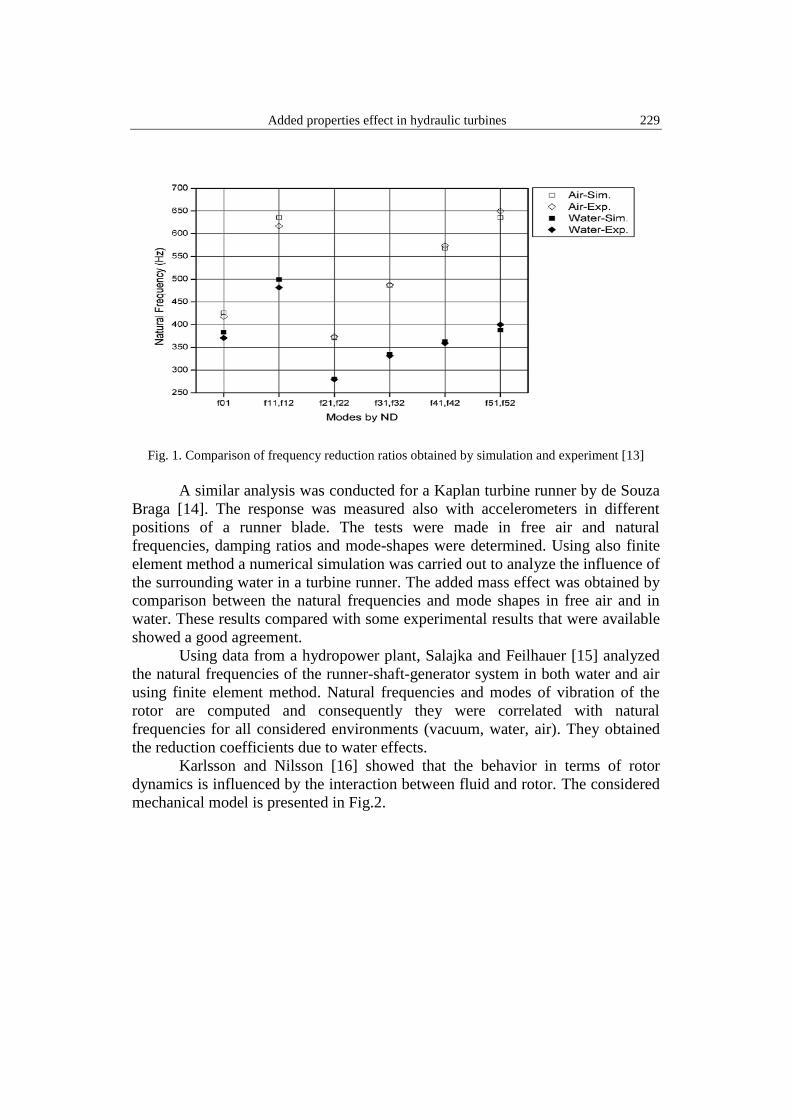
The mechanical design of hydraulic turbines is conditioned by the dynamic
response of the runner that is usually estimated by a computational model. Liang
and Rodriguez [13] aimed to obtain the effect of a given volume of water that
surrounds the Francis runner by finite element method. The numerical model was
based on the dynamic equation and the acoustic wave equation known as the
Helmholtz equation. Certain simplifications were also considered, like easy
compressible fluid, non-viscous, and the changes of density and pressure are very
small. Added inertia effect was determined by comparing the results obtained for
the natural frequencies of the simulations for water and air. Calculated frequencies
in the two cases were compared with the experimental ones. Mode shapes
between air and water were about the same even if frequency decreases
significantly. Maximum displacement was found in areas of the blade edge. The
results of the analysis are presented below, Fig.1, where the reduction of the
natural frequencies from air to water is observed, with simulated and experimental
results.
Added properties effect in hydraulic turbines 229
Fig. 1. Comparison of frequency reduction ratios obtained by simulation and experiment [13]
A similar analysis was conducted for a Kaplan turbine runner by de Souza
Braga [14]. The response was measured also with accelerometers in different
positions of a runner blade. The tests were made in free air and natural
frequencies, damping ratios and mode-shapes were determined. Using also finite
element method a numerical simulation was carried out to analyze the influence of
the surrounding water in a turbine runner. The added mass effect was obtained by
comparison between the natural frequencies and mode shapes in free air and in
water. These results compared with some experimental results that were available
showed a good agreement.
Using data from a hydropower plant, Salajka and Feilhauer [15] analyzed
the natural frequencies of the runner-shaft-generator system in both water and air
using finite element method. Natural frequencies and modes of vibration of the
rotor are computed and consequently they were correlated with natural
frequencies for all considered environments (vacuum, water, air). They obtained
the reduction coefficients due to water effects.
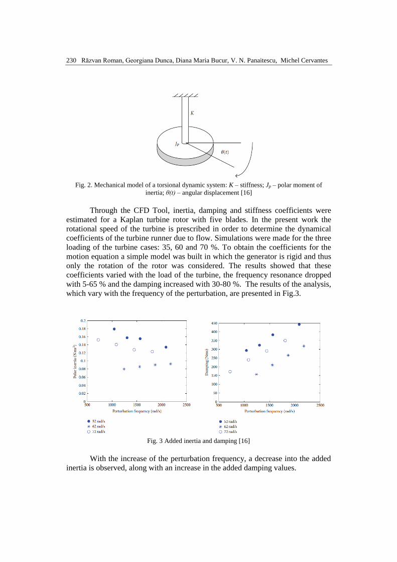
Karlsson and Nilsson [16] showed that the behavior in terms of rotor
dynamics is influenced by the interaction between fluid and rotor. The considered
mechanical model is presented in Fig.2.
230 Răzvan Roman, Georgiana Dunca, Diana Maria Bucur, V. N. Panaitescu, Michel Cervantes
Fig. 2. Mechanical model of a torsional dynamic system: K – stiffness; Jp – polar moment of
inertia; θ(t) – angular displacement [16]
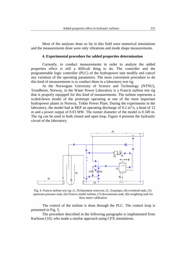
Through the CFD Tool, inertia, damping and stiffness coefficients were
estimated for a Kaplan turbine rotor with five blades. In the present work the
rotational speed of the turbine is prescribed in order to determine the dynamical
coefficients of the turbine runner due to flow. Simulations were made for the three
loading of the turbine cases: 35, 60 and 70 %. To obtain the coefficients for the
motion equation a simple model was built in which the generator is rigid and thus
only the rotation of the rotor was considered. The results showed that these
coefficients varied with the load of the turbine, the frequency resonance dropped
with 5-65 % and the damping increased with 30-80 %. The results of the analysis,
which vary with the frequency of the perturbation, are presented in Fig.3.
Fig. 3 Added inertia and damping [16]
With the increase of the perturbation frequency, a decrease into the added
inertia is observed, along with an increase in the added damping values.
Added properties effect in hydraulic turbines 231
Most of the analyses done so far in this field were numerical simulations
and the measurements done were only vibrations and mode shape measurements.
4. Experimental procedure for added properties determination
Currently, to conduct measurements in order to analyze the added
properties effect is still a difficult thing to do. The controller and the
programmable logic controller (PLC) of the hydropower unit modify and cancel
any variation of the operating parameters. The most convenient procedure to do
this kind of measurements is to conduct them in a laboratory test rig.
At the Norwegian University of Science and Technology (NTNU),
Trondheim, Norway, in the Water Power Laboratory is a Francis turbine test rig
that is properly equipped for this kind of measurements. The turbine represents a
scaled-down model of the prototype operating at one of the most important
hydropower plants in Norway, Tokke Power Plant. During the experiments in the
laboratory, the model had at BEP an operating discharge of 0.2 m3/s, a head of 12
m and a power output of 0.03 MW. The runner diameter of the model is 0.349 m.
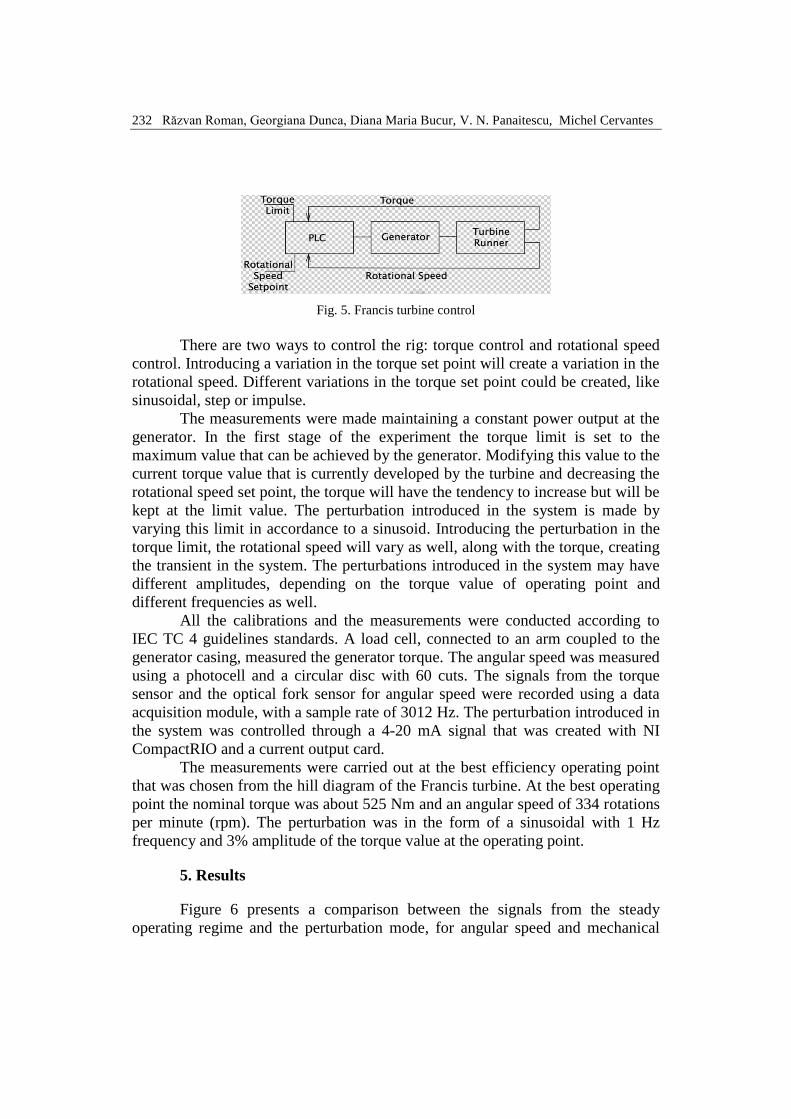
The rig can be used in both closed and open loop. Figure 4 presents the hydraulic
circuit of the laboratory.
Fig. 4. Francis turbine test rig: (1, 9)-basement reservoir; (2, 3)-pumps; (4)-overhead tank; (5)-
upstream pressure tank; (6)-Francis model turbine; (7)-downstream tank; (8)-weighting tank for
flow meter calibration
The control of the turbine is done through the PLC. The control loop is
presented in Fig. 5.
The procedure described in the following paragraphs is implemented from
Karlsson [16], who made a similar approach using CFX simulations.
232 Răzvan Roman, Georgiana Dunca, Diana Maria Bucur, V. N. Panaitescu, Michel Cervantes
Fig. 5. Francis turbine control
There are two ways to control the rig: torque control and rotational speed
control. Introducing a variation in the torque set point will create a variation in the
rotational speed. Different variations in the torque set point could be created, like
sinusoidal, step or impulse.
The measurements were made maintaining a constant power output at the
generator. In the first stage of the experiment the torque limit is set to the
maximum value that can be achieved by the generator. Modifying this value to the
current torque value that is currently developed by the turbine and decreasing the
rotational speed set point, the torque will have the tendency to increase but will be
kept at the limit value. The perturbation introduced in the system is made by
varying this limit in accordance to a sinusoid. Introducing the perturbation in the
torque limit, the rotational speed will vary as well, along with the torque, creating
the transient in the system. The perturbations introduced in the system may have
different amplitudes, depending on the torque value of operating point and
different frequencies as well.
All the calibrations and the measurements were conducted according to
IEC TC 4 guidelines standards. A load cell, connected to an arm coupled to the
generator casing, measured the generator torque. The angular speed was measured
using a photocell and a circular disc with 60 cuts. The signals from the torque
sensor and the optical fork sensor for angular speed were recorded using a data
acquisition module, with a sample rate of 3012 Hz. The perturbation introduced in
the system was controlled through a 4-20 mA signal that was created with NI
CompactRIO and a current output card.
The measurements were carried out at the best efficiency operating point
that was chosen from the hill diagram of the Francis turbine. At the best operating
point the nominal torque was about 525 Nm and an angular speed of 334 rotations
per minute (rpm). The perturbation was in the form of a sinusoidal with 1 Hz
frequency and 3% amplitude of the torque value at the operating point.
5. Results
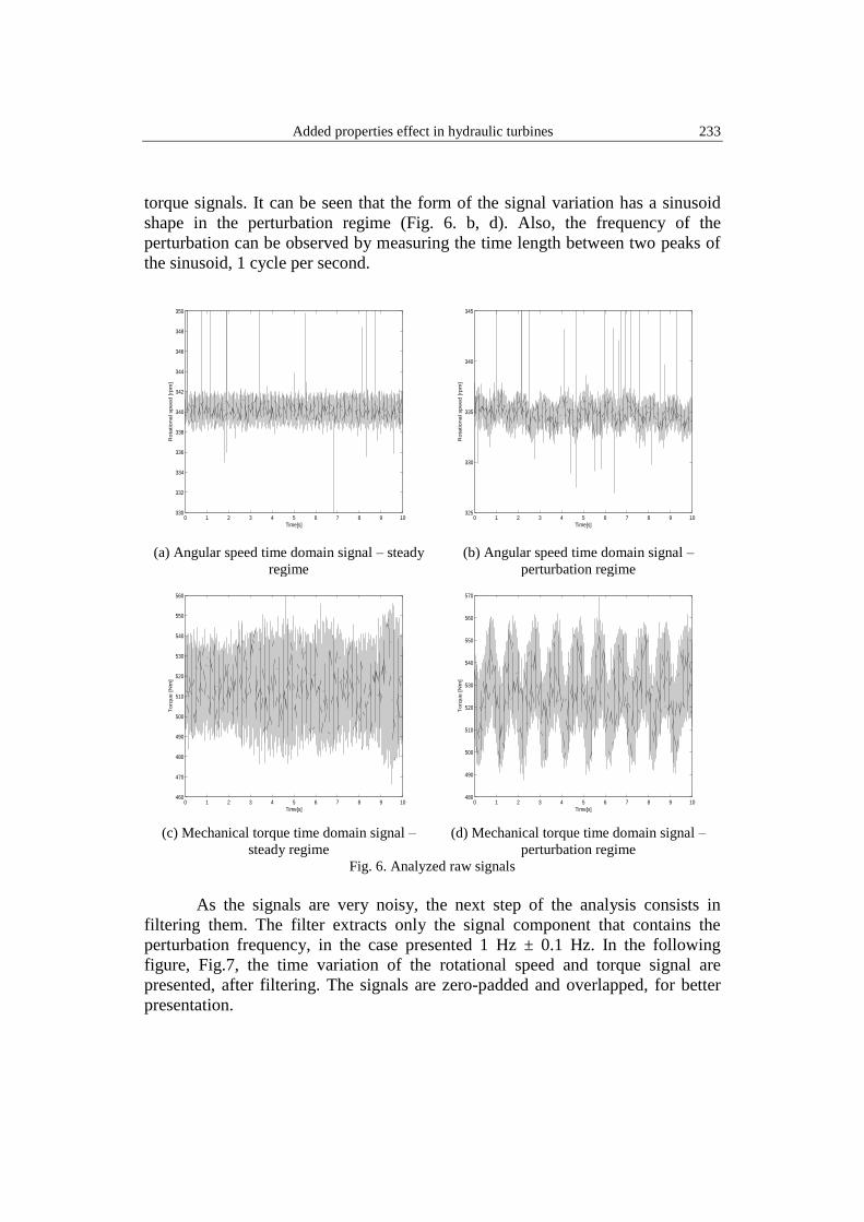
Figure 6 presents a comparison between the signals from the steady
operating regime and the perturbation mode, for angular speed and mechanical
Added properties effect in hydraulic turbines 233
torque signals. It can be seen that the form of the signal variation has a sinusoid
shape in the perturbation regime (Fig. 6. b, d). Also, the frequency of the
perturbation can be observed by measuring the time length between two peaks of
the sinusoid, 1 cycle per second.
(a) Angular speed time domain signal – steady
regime (b) Angular speed time domain signal –
perturbation regime
(c) Mechanical torque time domain signal –
steady regime (d) Mechanical torque time domain signal –
perturbation regime
Fig. 6. Analyzed raw signals
As the signals are very noisy, the next step of the analysis consists in
filtering them. The filter extracts only the signal component that contains the
perturbation frequency, in the case presented 1 Hz ± 0.1 Hz. In the following
figure, Fig.7, the time variation of the rotational speed and torque signal are
presented, after filtering. The signals are zero-padded and overlapped, for better
presentation.
0 1 2 3 4 5 6 7 8 9 10330
332
334
336
338
340
342
344
346
348
350
Time[s]
Ro
tational speed [
rpm
]
0 1 2 3 4 5 6 7 8 9 10325
330
335
340
345
Time[s]
Ro
tational speed [
rpm
]
0 1 2 3 4 5 6 7 8 9 10460
470
480
490
500
510
520
530
540
550
560
Time[s]
Torq
ue [N
m]
0 1 2 3 4 5 6 7 8 9 10480
490
500
510
520
530
540
550
560
570
Time[s]
Torq
ue [N
m]
234 Răzvan Roman, Georgiana Dunca, Diana Maria Bucur, V. N. Panaitescu, Michel Cervantes
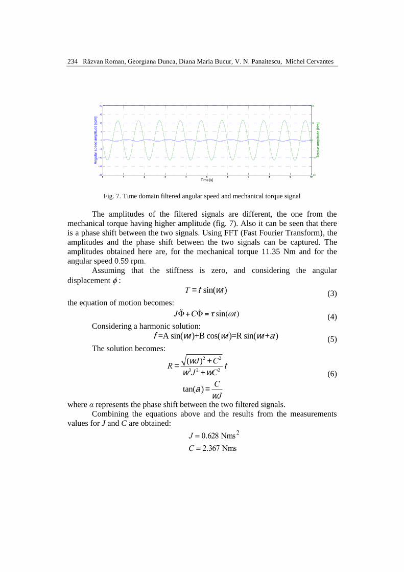
Fig. 7. Time domain filtered angular speed and mechanical torque signal
The amplitudes of the filtered signals are different, the one from the
mechanical torque having higher amplitude (fig. 7). Also it can be seen that there
is a phase shift between the two signals. Using FFT (Fast Fourier Transform), the
amplitudes and the phase shift between the two signals can be captured. The
amplitudes obtained here are, for the mechanical torque 11.35 Nm and for the
angular speed 0.59 rpm.
Assuming that the stiffness is zero, and considering the angular
displacement :
T = t sin(wt) (3)
the equation of motion becomes:
(4)
Considering a harmonic solution:
f=A sin(wt)+B cos(wt)=R sin(wt+a) (5)
The solution becomes:
R =
(wJ)2 +C2
w3J 2 +wC2t
(6)
tan(a) =
C
wJ
where α represents the phase shift between the two filtered signals.
Combining the equations above and the results from the measurements
values for J and C are obtained:
Nms 367.2
Nms 628.0 2
C
J
Added properties effect in hydraulic turbines 235
6. Conclusions
The added properties are an important aspect in turbines operation
nowadays and they need to be taken into consideration in the design stage and
also in the operating mode. The paper presents the state of the art for the added
properties topic, starting with the first experiments done for simple bodies and
geometries, continuing with the research done in the hydropower field, along with
an experimental procedure to determine them.
In the first step of the analysis, the experimental procedure implemented in
the NTNU laboratory presents good results that will lead to find the added
properties, for a Francis hydropower unit. Further research will be conducted for
obtaining the added properties in different operation conditions and for
characterizing the dynamic behavior of the turbine.
Acknowledgments The work has been funded by the Sectoral Operational Program Human
Resources Development 2007-2013 of the Ministry of European Funds through the
Financial Agreement POSDRU/159/1.5/S/134398.
The work has also been funded by the Executive Agency for Higher Education,
Research, Development and Innovation, PN-II-PT-PCCA-2013-4, ECOTURB project.
R E F E R E N C E S
[1]. Nicolet, Christophe, et al. "High-order modeling of hydraulic power plant in islanded power
network." Power Systems, IEEE Transactions on 22.4 (2007): 1870-1880.
[2]. Keck, H. and Sick, M., "Thirty Years of Numerical Flow Simulation in Hydraulic
Turbomachines," Acta Mech, 201, pp. 211-229, 2008. doi:10.1007/s00707-008-0060-4.
[3]. Brennen, C.E., A Review of Added Mass and Fluid Inertial Forces, Report CR 82.010, Naval
Civil Engineering Laboratory, Port Hueneme, California, 1982.
[4]. Iverson, H.W. and Balent, R. A correlating modulus for fluid resistance in accelerated motion,
Journal of Applied Physics, Vol.22, pp. 324-328.
[5]. Sarpkaya, Turgut, and Michael Isaacson. Mechanics of wave forces on offshore structures.
Vol. 96. New York: Van Nostrand Reinhold Company, 1981.
[6]. Stelson, Thomas E., and Frederic T. Mavis. "Virtual mass and acceleration in fluids."
Transactions of the American Society of Civil Engineers 122.1 (1957): 518-525.
[7]. Ermanyuk, E. V. "The rule of affine similitude for the force coefficients of a body oscillating
in a uniformly stratified fluid." Experiments in fluids 32.2 (2002): 242-251.
[8]. Cummins, W. E. The impulse response function and ship motions. No. DTMB-1661. David
Taylor Model Basin Washington DC, 1962.
[9]. Pérez, Tristan, and Thor I. Fossen. "Time-vs. frequency-domain identification of parametric
radiation force models for marine structures at zero speed." Modeling, Identification and
Control 29.1 (2008): 1-19.
236 Răzvan Roman, Georgiana Dunca, Diana Maria Bucur, V. N. Panaitescu, Michel Cervantes
[10]. McConnell, Kenneth G., and Donald F. Young. "Added mass of a sphere in a bounded
viscous fluid(Solid body motion in viscous fluid, discussing acceleration and added mass
concept)." American Society of Civil Engineers, Engineering Mechanics Division Journal
91 (1965): 147-164.
[11]. Yuanqi, Li, et al. "Added-mass estimation of flat membranes vibrating in still air." Journal of
Wind Engineering and Industrial Aerodynamics 99.8 (2011): 815-824.
[12]. Rodriguez, C. G., et al. "Experimental investigation of added mass effects on a Francis
turbine runner in still water." Journal of Fluids and Structures 22.5 (2006): 699-712.
[13]. Liang, Q. W., et al. "Numerical simulation of fluid added mass effect on a francis turbine
runner." Computers & fluids 36.6 (2007): 1106-1118.
[14]. de Souza Braga, Danilo, et al. "Numerical simulation of fluid added mass effect on a Kaplan
turbine runner with experimental validation." (2013).
[15]. Salajka, V., and V. Kanicky. "Natural vibrations of a five blade Kaplan turbine runner in
water." Colloquium Dynamics of Machines. 2000.
[16]. Karlsson, Martin, Håkan Nilsson, and Jan-Olov Aidanpää. "Numerical estimation of torsional
dynamic coefficients of a hydraulic turbine." International Journal of Rotating Machinery
2009 (2009).


![Hydraulic Turbines Od Thaper[1]](https://img.pdfslide.us/doc/110x75/553d462655034695438b45ba/hydraulic-turbines-od-thaper1.jpg)