Embed Size (px)
Citation preview
Program ALUMINIUM © 2014 Dlubal Software GmbH
Add-on Module
ALUMINIUM Ultimate and Serviceability Limit State Design and Stability Analysis according to Eurocode 9
Program Description
Version February 2014
All rights, including those of translations, are reserved.
No portion of this book may be reproduced – mechanically, electronically, or by any other means, including photocopying – without written permission of DLUBAL SOFTWARE GMBH. © Dlubal Software GmbH
Am Zellweg 2 D-93464 Tiefenbach
Tel.: +49 9673 9203-0
Fax: +49 9673 9203-51
E-Mail: [email protected]
Web: www.dlubal.com


3
Content
Content Page
Content Page
Program ALUMINIUM © 2014 Dlubal Software GmbH
1. Introduction 4 1.1 Add-on Module ALUMINIUM 4 1.2 ALUMINIUM Team 5 1.3 Using the Manual 6 1.4 Opening the ALUMINIUM Module 6 2. Input Data 8 2.1 General Data 8 2.1.1 Ultimate Limit State 10 2.1.2 Serviceability Limit State 12 2.1.3 National Annex (NA) 13 2.2 Materials 14 2.3 Cross-Sections 16 2.4 Intermediate Lateral Restraints 21 2.5 Transverse Welds 22 2.6 Effective Lengths - Members 24 2.7 Effective Lengths - Sets of Members 28 2.8 Nodal Support - Sets of Members 29 2.9 Member End Releases - Sets of Members 31 2.10 Serviceability Data 32 3. Calculation 33 3.1 Detail Settings 33 3.1.1 Ultimate Limit State 33 3.1.2 Stability 35 3.1.3 Serviceability 38 3.1.4 Other 39 3.2 Start Calculation 41 4. Results 42 4.1 Design by Load Case 43 4.2 Design by Cross-Section 44 4.3 Design by Set of Members 45 4.4 Design by Member 46 4.5 Design by x-Location 46 4.6 Governing Internal Forces by Member 47 4.7 Governing Internal Forces by Set of
Members 48
4.8 Member Slendernesses 49 4.9 Parts List by Member 50 4.10 Parts List by Set of Members 51 5. Evaluation of Results 52 5.1 Results on the RSTAB model 53 5.2 Result diagrams 55 5.3 Filter for Results 56 6. Printout 58 6.1 Printout Report 58 6.2 Graphic Printout 58 7. General Functions 60 7.1 Design Cases 60 7.2 Cross-Section Optimization 62 7.3 Units and Decimal Places 64 7.4 Data Exchange 65 7.4.1 Exporting Materials to RSTAB 65 7.4.2 Exporting Effective Lengths to RSTAB 65 7.4.3 Exporting Results 65 8. Worked Example: Column
Subject to Biaxial Bending 67 8.1 Design values 67 8.2 Cross-Section Properties 68 8.3 Classification 68 8.4 Effective Cross-Section Properties 71 8.5 Flexural Buckling About Major Axis (⊥ to
y-y) 72 8.6 Flexural Buckling About Minor Axis (⊥ to
z-z) 73 8.7 Torsional Buckling About Longitudinal
Axis (About x-x) 74 8.8 Torsional-Flexural Buckling 74 8.9 Bending with Axial Compression 76 A Literature 80
B Index 81

1 Introduction
4 Program ALUMINIUM © 2014 Dlubal Software GmbH
1. Introduction
1.1 Add-on Module ALUMINIUM
Eurocode 9 (EN 1999-1-1:2007) provides design rules for aluminium structures in the member states of the EU. The RSTAB add-on module ALUMINIUM by DLUBAL is a powerful tool for design-ing aluminium modeld. Country-specific provisions are considered in the National Annexes. In addition to the parameters given in the program, you can define your own limit values or cre-ate new National Annexes.
ALUMINIUM carries out all typical ultimate limit state designs, stability analyses, and the de-formation analysis. In the ultimate limit state design, the module considers the action of vari-ous internal forces. You have also the option to select one of the interaction checks given in the standard. Dividing cross-sections into the classes 1 through 4 is an important part of the cross-sections selected for design. In this way, the program checks the limit of the resistance and rotational capacity by local buckling of cross-section parts. ALUMINIUM determines the c/t-ratios of the cross-section parts in compression and runs the classification automatically.
In case of member segments connected by weld seams, the softening in the heat-affected zone (HAZ) can be taken into account.
For the stability analyses, you can define for each member or set of members separately, if buckling in y- and/or z-direction is possible. You can also define additional intermediate lateral restraints for realistic modeling. From the boundary conditions, ALUMINIUM determines the slenderness ratios and the elastic critical buckling loads. The elastic critical moment for lateral-torsional buckling necessary for the lateral-torsional buckling check can be determined auto-matically or specified manually. The point of shear load application is considered, which has a decisive effect on torsion.
The serviceability limit state design is important for slender aluminium sections. For this de-sign, you can assign load cases, load combinations, and result combinations to the various de-sign situations. The limit deformations are preset through the National Annex. If necessary, you can adjust them. Furthermore, you can specify reference lengths and precambers, which will be considered accordingly in the design.
If necessary, the module carries out an optimization of the cross-sections and exports the changed cross-sections to RSTAB. Using the design cases, you can analyze separate structural components in complex models or analyze variants.
ALUMINIUM is an add-on module integrated in RSTAB. Thus, the design-relevant input data is already preset when you start the module. After the design, you can evaluate the results in the graphical user interface of RSTAB. Finally, you can document the analyses in the global printout report of RSTAB, from determination of internal forces to design.
We hope you enjoy working with ALUMINIUM.
Your DLUBAL Team

1 Introduction
5 Program ALUMINIUM © 2014 Dlubal Software GmbH
1.2 ALUMINIUM Team The following people were involved in the development of ALUMINIUM:
Program coordination Dipl.-Ing. Georg Dlubal Ing. Ph.D. Martin Čudejko
Dipl.-Ing. (FH) Younes El Frem
Programming Ing. Zdeněk Kosáček Ing. Ph.D. Martin Čudejko Dr.-Ing. Jaroslav Lain Ing. Martin Budáč
Mgr. Petr Oulehle Zbyněk Zámečník DiS. Jiří Šmerák
Cross-section and material library Ing. Ph.D. Jan Rybín Ing. Jiří Kubíček
Program design, dialog box figures, and icons Dipl.-Ing. Georg Dlubal MgA. Robert Kolouch
Ing. Jan Miléř
Program testing Ing. Martin Vasek Dipl.-Ing. (FH) René Flori
Localization, manual Ing. Fabio Borriello Ing. Dmitry Bystrov Ing. Ph.D. Martin Čudejko Eng.º Rafael Duarte Ing. Jana Duníková Dipl.-Ing. (FH) René Flori Ing. Lara Freyer Alessandra Grosso Bc. Chelsea Jennings Ing. Ladislav Kábrt Ing. Aleksandra Kociołek
Ing. Roberto Lombino Eng.º Nilton Lopes Mgr. Ing. Hana Macková Ing. Téc. Ind. José Martínez MA Translation Anton Mitleider Dipl.-Ü. Gundel Pietzcker Mgr. Petra Pokorná Ing. Michaela Prokopová Ing. Marcela Svitáková Dipl.-Ing. (FH) Robert Vogl Ing. Marcin Wardyn
Technical support and final testing M.Eng. Cosme Asseya Dipl.-Ing. (BA) Markus Baumgärtel Dipl.-Ing. Moritz Bertram Dipl.-Ing. (FH) Steffen Clauß Dipl.-Ing. Frank Faulstich Dipl.-Ing. (FH) René Flori Dipl.-Ing. (FH) Stefan Frenzel Dipl.-Ing. (FH) Walter Fröhlich Dipl.-Ing. (FH) Wieland Götzler
Dipl.-Ing. (FH) Bastian Kuhn Dipl.-Ing. (FH) Ulrich Lex Dipl.-Ing. (BA) Sandy Matula M.Eng. Dipl.-Ing. (BA) Andreas Niemeier M.Eng. Dipl.-Ing. (FH) Walter Rustler M.Sc. Dipl.-Ing. (FH) Frank Sonntag Dipl.-Ing. (FH) Christian Stautner Dipl.-Ing. (FH) Lukas Sühnel Dipl.-Ing. (FH) Robert Vogl
1 Introduction
6 Program ALUMINIUM © 2014 Dlubal Software GmbH
1.3 Using the Manual Topics like installation, graphical user interface, results evaluation, and printout are described in detail in the manual of the main program RSTAB. The present manual focuses on typical fea-tures of the ALUMINIUM add-on module.
The descriptions in this manual follow the sequence and structure of the module's input and results windows. In the text, the buttons are given in square brackets, for example [View mode]. At the same time, they are pictured on the left. The Expressions that appear in dialog boxes, windows, and menus are set in italics to clarify the explanations.
At the end of the manual, you find the index. If you still cannot find what you are looking for, please check our website www.dlubal.com, where you can go through the FAQ pages and find a solution by using various filter criteria.
1.4 Opening the ALUMINIUM Module In RSTAB, you have the following possibilities to start the add-on module ALUMINIUM.
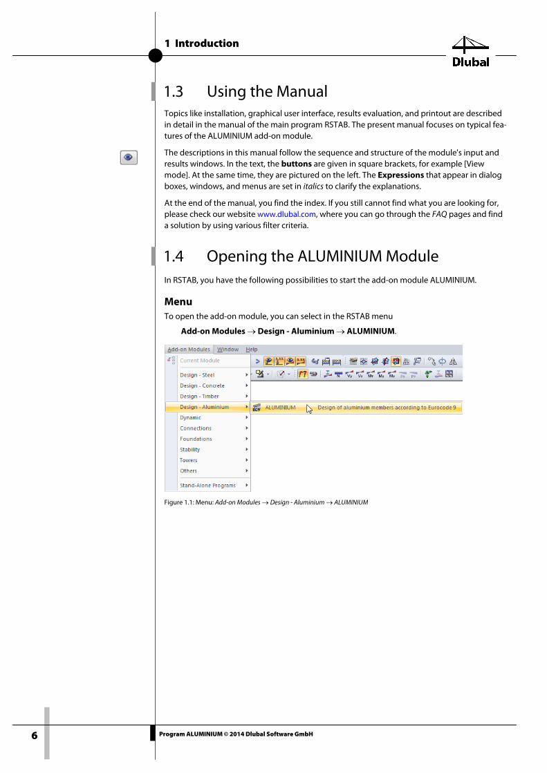
Menu To open the add-on module, you can select in the RSTAB menu
Add-on Modules → Design - Aluminium → ALUMINIUM.
Figure 1.1: Menu: Add-on Modules → Design - Aluminium → ALUMINIUM
1 Introduction
7 Program ALUMINIUM © 2014 Dlubal Software GmbH
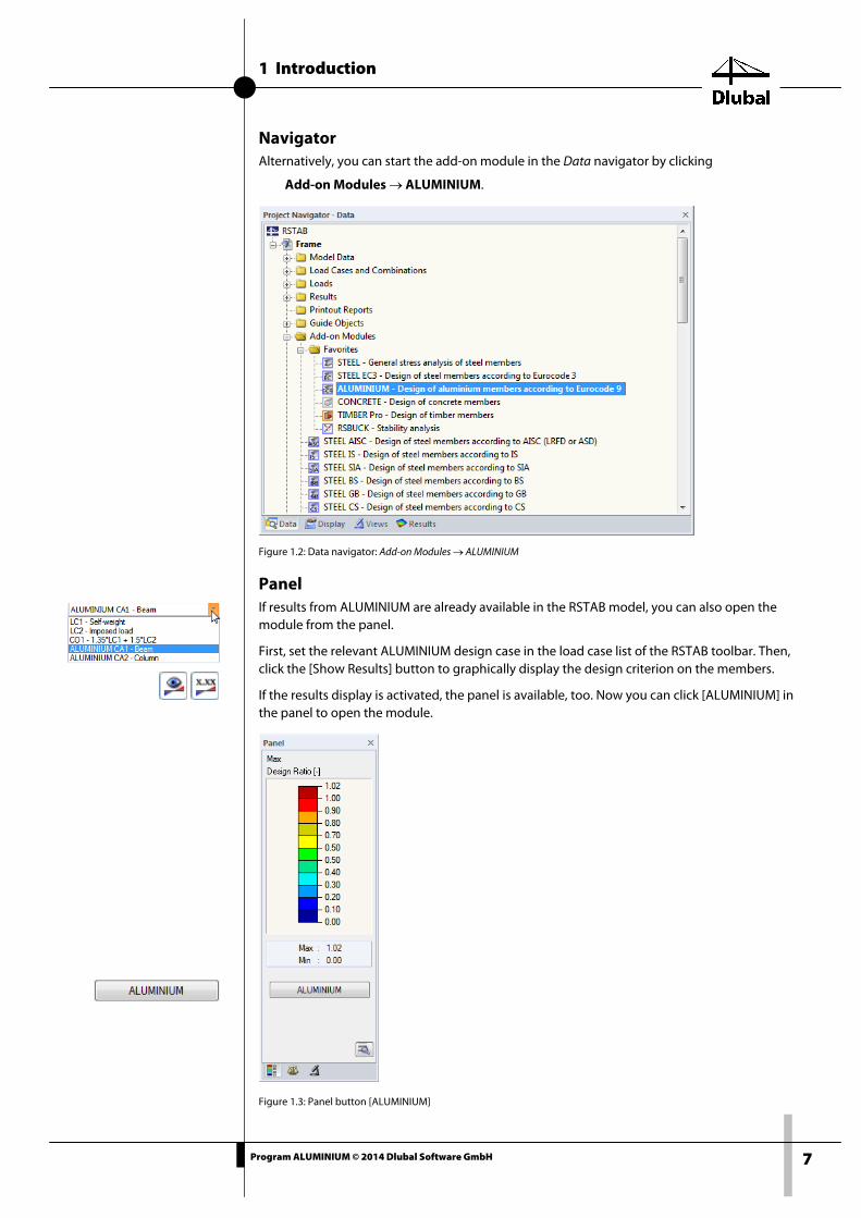
Navigator Alternatively, you can start the add-on module in the Data navigator by clicking
Add-on Modules → ALUMINIUM.
Figure 1.2: Data navigator: Add-on Modules → ALUMINIUM
Panel If results from ALUMINIUM are already available in the RSTAB model, you can also open the module from the panel.
First, set the relevant ALUMINIUM design case in the load case list of the RSTAB toolbar. Then, click the [Show Results] button to graphically display the design criterion on the members.
If the results display is activated, the panel is available, too. Now you can click [ALUMINIUM] in the panel to open the module.
Figure 1.3: Panel button [ALUMINIUM]

2 Input Data
8 Program ALUMINIUM © 2014 Dlubal Software GmbH
2. Input Data When you start the add-on module, a new window opens. In this window, a navigator is dis-played on the left that manages the available input and output windows. The drop-down list above the navigator contains the design cases (see Chapter 7.1, page 60).
The design-relevant data is to be defined in several input windows. When you open ALUMINIUM for the first time, the following parameters are imported automatically:
• Members and sets of members
• Load cases, load combinations, result combinations, and super combinations
• Materials
• Cross-sections
• Effective lengths
• Internal forces (in the background, if calculated)
To select a window, click the corresponding entry in the navigator. To go to the previous or next input window, use the buttons shown on the left. You can also use the function keys to select the next [F2] or previous [F3] window.
To save the results, click [OK]. Thus, you exit ALUMINIUM and return to the main program. To exit the module without saving the new data, click [Cancel].
2.1 General Data In the 1.1 General Data window, you select the members, sets of members, and actions that you want to analyze. The tabs manage the load cases, load combinations, result combinations, and super combinations for the ultimate and serviceability limit state designs.
Figure 2.1: Window 1.1 General Data
2 Input Data
9 Program ALUMINIUM © 2014 Dlubal Software GmbH
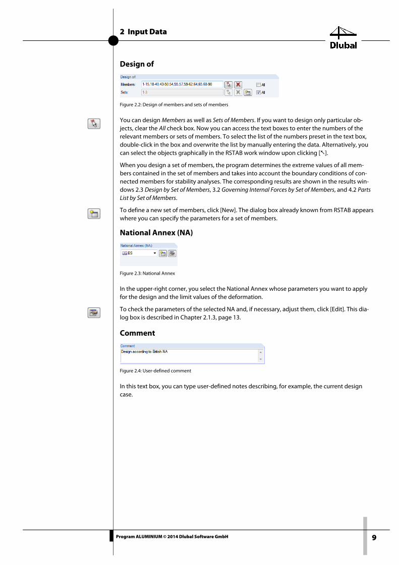
Design of
Figure 2.2: Design of members and sets of members
You can design Members as well as Sets of Members. If you want to design only particular ob-jects, clear the All check box. Now you can access the text boxes to enter the numbers of the relevant members or sets of members. To select the list of the numbers preset in the text box, double-click in the box and overwrite the list by manually entering the data. Alternatively, you can select the objects graphically in the RSTAB work window upon clicking [].
When you design a set of members, the program determines the extreme values of all mem-bers contained in the set of members and takes into account the boundary conditions of con-nected members for stability analyses. The corresponding results are shown in the results win-dows 2.3 Design by Set of Members, 3.2 Governing Internal Forces by Set of Members, and 4.2 Parts List by Set of Members.
To define a new set of members, click [New]. The dialog box already known from RSTAB appears where you can specify the parameters for a set of members.
National Annex (NA)
Figure 2.3: National Annex
In the upper-right corner, you select the National Annex whose parameters you want to apply for the design and the limit values of the deformation.
To check the parameters of the selected NA and, if necessary, adjust them, click [Edit]. This dia-log box is described in Chapter 2.1.3, page 13.
Comment
Figure 2.4: User-defined comment
In this text box, you can type user-defined notes describing, for example, the current design case.

2 Input Data
10 Program ALUMINIUM © 2014 Dlubal Software GmbH
2.1.1 Ultimate Limit State
Figure 2.5: Window 1.1 General Data, tab Ultimate Limit State
Existing Load Cases and Combinations This dialog box section contains all load cases, load combinations, and result combinations created in RSTAB.
To transfer the selected entries to the To Design dialog box section, click []. Alternatively, you can just double-click them. To transfer the entire list to the right, click [].
To transfer multiple entries at once, select them while pressing the [Ctrl] key, as common in Windows applications.
If a load case is highlighted in red, for example, LC6 or LC7 in Figure 2.5, this means that it can-not be designed. This happens when the load cases are defined without any load data or the load cases contain only imperfections. When you transfer such a load case, a corresponding warning appears.
At the end of the list, several filter options are available. They will help you assign the entries sorted by load case, load combination, or action category. The buttons have the following functions:
Selects all cases in the list.
Inverts selection of load cases.
Table 2.1: Buttons in the tab Ultimate Limit State

2 Input Data
11 Program ALUMINIUM © 2014 Dlubal Software GmbH
Design of The section on the right contains the load cases, load combinations, and result combinations selected for design. To remove selected entries from the list, click [] or double-click the en-tries. To transfer the entire list to the left, click [].
You can assign the load cases, load combinations, and result combinations to the following design situations:
• Persistent and Transient
• Accidental
This classification controls the partial safety factors γM0, γM1, and γM2 that are included in the determination of the resistances Rd for the cross-section and stability analyses (see Figure 2.9, page 13).
To change the design situation, use the list at the end of the dialog box section. To open the list, click the drop-down arrow [].
Figure 2.6: Assigning design situation
To transfer multiple entries at once, select them while pressing the [Ctrl] key, as common in Windows applications.
Designing an enveloping max/min result combination is faster than designing all contained load cases and load combinations. But designing a result combination also has its disadvan-tages: First, the influence of the contained actions is difficult to discern. Second, for the deter-mination of the elastic critical moment for LTB, Mcr, the envelope of the moment distributions is analyzed, from which the most unfavorable distribution (max or min) is taken. However, this distribution only rarely reflects the moment distribution in the individual load combinations. Thus, in the case of an RC design, more unfavorable values for Mcr are to be expected, leading to higher design ratios.
Result combinations should be selected only for dynamic combinations. For "normal" combi-nations, load combinations are recommended, because here the actual moment distributions are taken for the determination of Mcr.
Result combination

2 Input Data
12 Program ALUMINIUM © 2014 Dlubal Software GmbH
2.1.2 Serviceability Limit State
Figure 2.7: Window 1.1 General Data, tab Serviceability Limit State
Existing Load Cases and Combinations This dialog box section contains all load cases, load combinations, result combinations, and super combinations created in RSTAB.
Design of Load cases, load combinations, and result combinations can be added or removed as described in Chapter 2.1.1.
You can assign different deflection limit values to the load cases, load combinations, and result combinations. You can select from the following design situations:
• Characteristic
• Frequent
• Quasi-permanent
To change the design situation, select it in the list at the end of the entry after clicking [] (see Figure 2.7).
The deflection limits are defined in the National Annex. To adjust these values for the design situations, click [Nat. Annex] and modify them in the appearing National Annex Settings dialog box (see Figure 2.9, page 13).
The 1.10 Serviceability Data window manages the reference lengths governing for the defor-mation check (see Chapter 2.10, page 32).

2 Input Data
13 Program ALUMINIUM © 2014 Dlubal Software GmbH
2.1.3 National Annex (NA) In the upper-right list of the 1.1 General Data window, you can select the National Annex whose parameters apply to the design and the limit values of the deformation.
Figure 2.8: Selecting the National Annex
To check and, if necessary, adjust the preset parameters, click [Edit] (see the following figure).
To create a user-defined National Annex, click [New].
Alternatively, you can use the [Nat. Annex] button available in all input windows in order to open the National Annex Settings dialog box.
Figure 2.9: Dialog box National Annex Settings - BS
In the first dialog box sections, you can check and, if necessary, change the Partial Factors Acc. to 6.1.3, and in the section on the left the Serviceability Limits (Deflections) Acc. to 7.2. Further-more, you can specify the maximum utilization for the General Triaxial State of Stress in Section.

2 Input Data
14 Program ALUMINIUM © 2014 Dlubal Software GmbH
The buttons at the bottom of the dialog box have the following functions:
Table 2.2: Buttons in the dialog box National Annex Settings
2.2 Materials The window is subdivided into two parts. The upper part shows all materials used in RSTAB. The Material Properties dialog box section shows the properties of the current material, that is, the table row currently selected in the upper section.
Figure 2.10: Window 1.2 Materials
Materials that will not be used for the design appear in grey. Materials that are not allowed appear in red. Changed materials appear in blue.
The material properties required for the determination of internal forces are described in Chapter 4.2 of the RSTAB manual (Main Properties). The material properties required for the design are stored in the global material library. These values are preset (Additional Properties).
To adjust the units and decimal places of material properties and stresses, select in the menu Settings → Units and Decimal Places (see Chapter 7.3, page 64).
Button Function
Resets the program's default settings
Sets the user-defined settings
Saves the modified settings as user-defined default settings
Deletes the user-defined National Annex.

2 Input Data
15 Program ALUMINIUM © 2014 Dlubal Software GmbH
Material Description The materials defined in RSTAB are preset but can be changed at any time. To do this, click the material in column A. Then, click [] or press function key [F7] to open the material list.
Figure 2.11: List of materials
According to standard [1], you can select only materials of the "Aluminium" category. Only al-loys can be designed that are covered by [1], Table 3.2a, b, and c. For this reason, you cannot edit the material properties in the module. ALUMINIUM checks neither the product form of the material according to [1], Table 3.2b nor the shape of the cross-section.
After you import a material, the design relevant Material Properties are updated.
If you change the material description manually and your entry is stored in the material library, ALUMINIUM will import the material properties, too.
Material Library Numerous materials are already available in the library. To open it, select in the menu
Edit → Material Library
or use the button shown on the left.
Figure 2.12: Dialog box Material Library

2 Input Data
16 Program ALUMINIUM © 2014 Dlubal Software GmbH
In the Filter section, Aluminium is preset as the material category. To select an alloy for design, use the Material to Select drop-down list. You can check the corresponding properties in the dialog box section below.
To transfer the selected material to Window 1.2 of ALUMINIUM, click [OK] or [↵].
Chapter 4.2 of the RSTAB manual describes how to filter, add, or rearrange materials.
2.3 Cross-Sections This window manages the cross-sections that are used for the design. In addition, you can specify optimization parameters in this window.
Figure 2.13: Window 1.3 Cross-Section
Cross-Section Description The cross-sections defined in RSTAB are preset together with the assigned material numbers.
To change a cross-section, click the entry in column B, thus selecting this cell. To open the cross-section row of the current text box, click [Cross-Section Library] or [...] in the text box or press the function key [F7] (see Figure 2.14).
In this dialog box, you can select a different cross-section or a different cross-section row. To select a different cross-section category, click [Back to cross-section library]. The general cross-section library opens.
Chapter 4.3 of the RSTAB manual describes how cross-sections can be selected from the library.

2 Input Data
17 Program ALUMINIUM © 2014 Dlubal Software GmbH
ALUMINIUM performs all necessary designs for the following cross-section types:
• I-sections: rolled/welded, doubly symmetrical or mono-symmetric about the z-axis
• Hollow and box sections: rolled/welded, square-edged/rectangular, doubly-symmetrical
• Massive cross-sections: circular/rectangular
• Pipes
• Angles: rolled/welded simple sections with equal or unequal legs
• T-sections: rolled/welded, symmetrical about z-axis
• Channel-sections: rolled/welded, symmetrical about y-axis
ALUMINIUM also designs other cross-sections from the library or SHAPE-THIN. For these sec-tions of the "General" type, however, not all design options are available.
Figure 2.14: Cross-section of the type General (stored)
You can also enter the new cross-section description in the text box directly. If the data base contains the entry, ALUMINIUM imports the corresponding cross-section properties, too.
A modified cross-section is highlighted in blue.
If cross-sections specified in ALUMINIUM differ from those used in RSTAB, both cross-sections are displayed in the graphic on the right. The designs are carried out with the internal forces from RSTAB for the cross-section selected in ALUMINIUM.
The welded types of cross-section are parametric sections that are manufactured by welding plates. Note for ALUMINIUM that the design of these weld seams (HAZ effects) is currently not implemented.

2 Input Data
18 Program ALUMINIUM © 2014 Dlubal Software GmbH
Cross-Section Type for Classification This column shows the cross-section type used for the classification. According to [1], Clause 6.1.4, the cross-sections can be designed elastically or plastically, depending on the class. Cross-sections that are not completely covered by the provisions of the standard are classified as General (see Figure 2.14). These can be designed only elastically (class 3 or 4).
Max. Design Ratio This column is displayed only after the calculation. It serves as a decision support for the opti-mization. By means of the displayed design ratio and colored reference scales, you can see which cross-sections are little utilized and thus oversized, or overstressed and thus undersized.
Optimize Each cross-section can undergo an optimization process. For the RSTAB internal forces, the program searches the cross-section that comes as close as possible to a user-defined maxi-mum design ratio. This ratio can be specified in the General tab of the Details dialog box (see Figure 3.4, page 39).
To optimize a cross-section, open the drop-down list in column D or E and select the relevant entry: From current row or, if available, From favorites 'Description‘. Recommendations for the cross-section optimization can be found in Chapter 7.2, page 62.
Remark This column shows remarks in the form of footers that are described in detail below the cross-section list.
A warning might appear before the calculation: Incorrect type of cross-section No. XX. This means that there is a cross-section that is not registered in the data base. This can be a user-defined cross-section or a SHAPE-THIN cross-section that has not been calculated yet. To select an appropriate cross-section for design, click [Library] (see description after Figure 2.13).
Member with Tapered Cross-Section ALUMINIUM does not support the design of tapered members with different cross-sections at both ends of the member. If you try to design them, the following message appears:
Figure 2.15: Message appearing when designing a taper
2 Input Data
19 Program ALUMINIUM © 2014 Dlubal Software GmbH
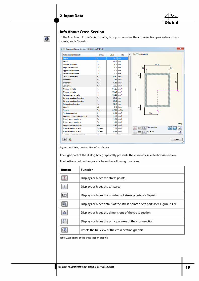
Info About Cross-Section In the Info About Cross-Section dialog box, you can view the cross-section properties, stress points, and c/t-parts.
Figure 2.16: Dialog box Info About Cross-Section
The right part of the dialog box graphically presents the currently selected cross-section.
The buttons below the graphic have the following functions:
Table 2.3: Buttons of the cross-section graphic
Button Function
Displays or hides the stress points
Displays or hides the c/t-parts
Displays or hides the numbers of stress points or c/t-parts
Displays or hides details of the stress points or c/t-parts (see Figure 2.17)
Displays or hides the dimensions of the cross-section
Displays or hides the principal axes of the cross-section
Resets the full view of the cross-section graphic
2 Input Data
20 Program ALUMINIUM © 2014 Dlubal Software GmbH
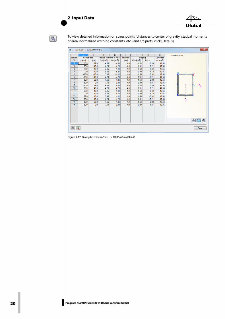
To view detailed information on stress points (distances to center of gravity, statical moments of area, normalized warping constants, etc.) and c/t-parts, click [Details].
Figure 2.17: Dialog box Stress Points of TO 80/60/4/4/4/4/K
2 Input Data
21 Program ALUMINIUM © 2014 Dlubal Software GmbH
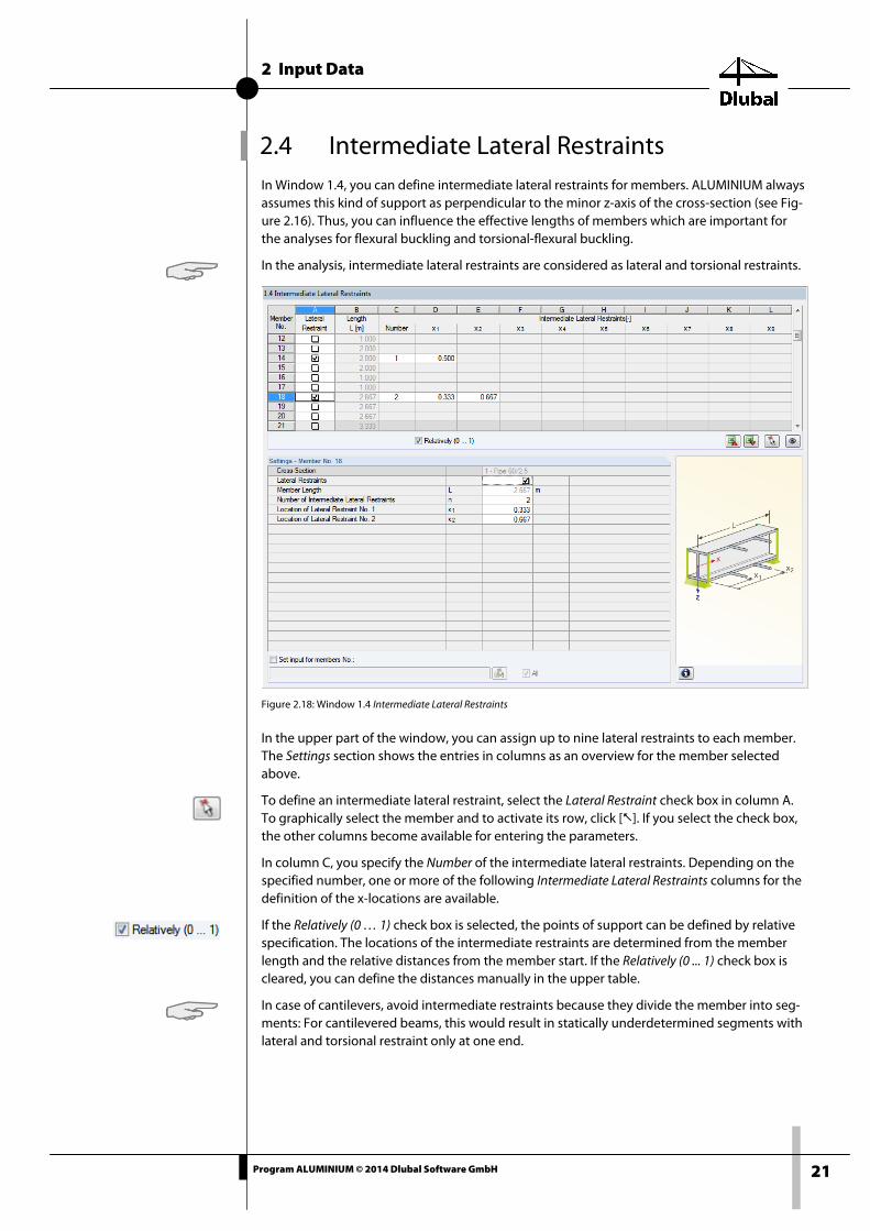
2.4 Intermediate Lateral Restraints In Window 1.4, you can define intermediate lateral restraints for members. ALUMINIUM always assumes this kind of support as perpendicular to the minor z-axis of the cross-section (see Fig-ure 2.16). Thus, you can influence the effective lengths of members which are important for the analyses for flexural buckling and torsional-flexural buckling.
In the analysis, intermediate lateral restraints are considered as lateral and torsional restraints.
Figure 2.18: Window 1.4 Intermediate Lateral Restraints
In the upper part of the window, you can assign up to nine lateral restraints to each member. The Settings section shows the entries in columns as an overview for the member selected above.
To define an intermediate lateral restraint, select the Lateral Restraint check box in column A. To graphically select the member and to activate its row, click []. If you select the check box, the other columns become available for entering the parameters.
In column C, you specify the Number of the intermediate lateral restraints. Depending on the specified number, one or more of the following Intermediate Lateral Restraints columns for the definition of the x-locations are available.
If the Relatively (0 … 1) check box is selected, the points of support can be defined by relative specification. The locations of the intermediate restraints are determined from the member length and the relative distances from the member start. If the Relatively (0 ... 1) check box is cleared, you can define the distances manually in the upper table.
In case of cantilevers, avoid intermediate restraints because they divide the member into seg-ments: For cantilevered beams, this would result in statically underdetermined segments with lateral and torsional restraint only at one end.

2 Input Data
22 Program ALUMINIUM © 2014 Dlubal Software GmbH
2.5 Transverse Welds If segments of members are connected by weld seams, you can specify their arrangement and detailing in Window 1.5. In this way, you can take into account the HAZ softening of the cross-section.
The Designers' Guide to Eurocode 9 [3] provides further information on the topic "transverse welds."
To select a member graphically and show its corresponding row, click [].
Changes are possible in the table as well as in the Settings tree.
Figure 2.19: Window 1.5 Transverse Welds
Transverse Welds To define a transverse weld, select the check box in column A. Thus, further columns for speci-fying parameters become available.
Length L This column shows the corresponding member lengths.
Transverse Welds
Number
Column C allows you to specify the Number of the weld seams. You can specify up to four transverse welds for each member. In the next columns, you then can specify the x-locations.
x1 / x2 / x3 / x4
If the Relatively (0 … 1) check box is selected, you can define the locations of the transverse welds by means of relative input: They result from the member length and the relative dis-tances from the member start. To specify the distances by their length, clear the selection of the Relatively (0 … 1) check box.

2 Input Data
23 Program ALUMINIUM © 2014 Dlubal Software GmbH
Weld Type In this column, you specify the type of the weld seam. You can select from one of two options: butt and fillet. The weld type has an influence on the expansion of the heat-affected zone (see [1], Clause 6.1.6.3).
Method The welding procedure also has an influence on the expansion of the heat-affected zone. In column I, you can specify either the MIG or the TIG method.
Material In the list, you can select heat-treatable alloys of temper T4 and above (6xxx and 7xxx series) as well as non-heat-treatable alloys in any work-hardened condition (3xxx, 5xxx, and 8xxx series). They have an influence on the characteristic strengths fo,haz and fu,haz.
Temperature If the temperature is above 60 °C, there could be a build-up of temperature between weld seam passes. This increases the extent of the heat-affected zone (see [1], Clause 6.1.6.3 (8)).
No. of Heat Paths In the last column, you specify the number of valid heat paths.
Below the Settings table, you find the Set input for members No. check box. If selected, the set-tings entered afterwards will be applied to the selected (manual entry of member numbers or graphical selection by means of []) or All members.
2 Input Data
24 Program ALUMINIUM © 2014 Dlubal Software GmbH
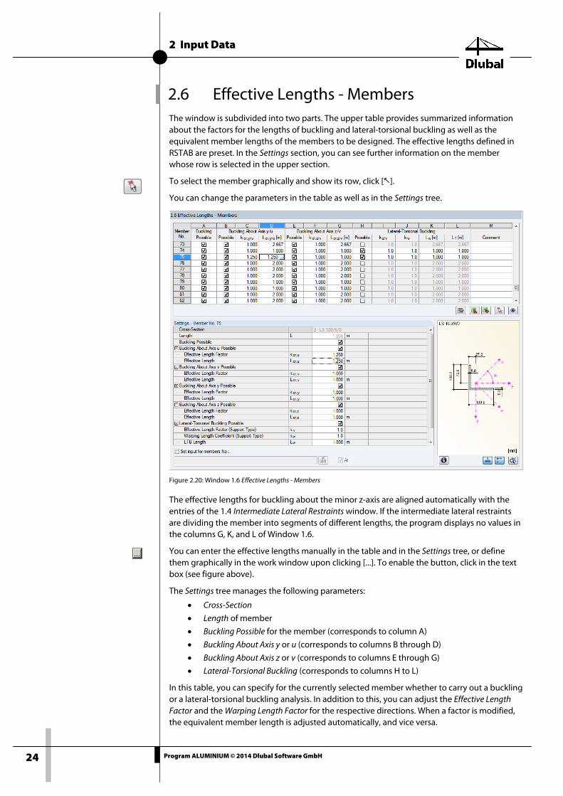
2.6 Effective Lengths - Members The window is subdivided into two parts. The upper table provides summarized information about the factors for the lengths of buckling and lateral-torsional buckling as well as the equivalent member lengths of the members to be designed. The effective lengths defined in RSTAB are preset. In the Settings section, you can see further information on the member whose row is selected in the upper section.
To select the member graphically and show its row, click [].
You can change the parameters in the table as well as in the Settings tree.
Figure 2.20: Window 1.6 Effective Lengths - Members
The effective lengths for buckling about the minor z-axis are aligned automatically with the entries of the 1.4 Intermediate Lateral Restraints window. If the intermediate lateral restraints are dividing the member into segments of different lengths, the program displays no values in the columns G, K, and L of Window 1.6.
You can enter the effective lengths manually in the table and in the Settings tree, or define them graphically in the work window upon clicking [...]. To enable the button, click in the text box (see figure above).
The Settings tree manages the following parameters:
• Cross-Section
• Length of member
• Buckling Possible for the member (corresponds to column A)
• Buckling About Axis y or u (corresponds to columns B through D)
• Buckling About Axis z or v (corresponds to columns E through G)
• Lateral-Torsional Buckling (corresponds to columns H to L)
In this table, you can specify for the currently selected member whether to carry out a buckling or a lateral-torsional buckling analysis. In addition to this, you can adjust the Effective Length Factor and the Warping Length Factor for the respective directions. When a factor is modified, the equivalent member length is adjusted automatically, and vice versa.

2 Input Data
25 Program ALUMINIUM © 2014 Dlubal Software GmbH
You can also define the effective length of a member in a dialog box. To open it, click the button shown on the left. It is located on the right below the upper table of the window.
Figure 2.21: Dialog box Select Effective Length Factor
The effective length factors kcr,y and kcr,z correspond to the following definitions in [1], Table 6.8:
k = 0.70 held in position at both ends + restrained at both ends
k = 0.85 held in position at both ends + restrained at both ends
k = 1.00 held in position at both ends + not restrained at both ends
k = 1.25 held in position at one end + restrained at both ends
k = 1.50 held in position and restrained at one end + not held in position and partially restrained at the other end
k = 2.00 held in position and restrained at one end + free at the other end
The effective length factor can also be specified as User-defined. If you performed an eigen-value analysis in the RSBUCK add-on module, you can select a Buckling mode for determining the factor.
Buckling Possible The stability analyses for flexural buckling and lateral-torsional buckling require that members can resist compressive forces. Members for which such resistance is not possible because of the member type (for example, tension members, elastic foundations, rigid couplings) are ex-cluded from design in the first place. The corresponding rows appear dimmed and a message is displayed in the Comment column.
The Buckling Possible check boxes in table column A Settings tree offer you a control option for the stability analyses: By using them, you determine whether the analyses should or should not be performed for a member.

2 Input Data
26 Program ALUMINIUM © 2014 Dlubal Software GmbH
Buckling About Axis y or z With the check boxes in the Possible columns, you decide whether a member is susceptible to buckling about the y-axis and/or z-axis. These axes represent the local member axes, where the y-axis is the major and the z-axis the minor member axis. You can freely select the effective length factors kcr,y and kcr,z according to [1], Table 6.8 for buckling about the major or the minor axis.
You can check the position of the member axes in the cross-section graphic in the 1.3 Cross-Sections window (see Figure 2.13, page 16). To go to the RSTAB work window, click [View mode]. In the work window, you can display the local member axes by using the context menu of the member or the Display navigator (see Figure below).
Figure 2.22: Activating the member axis systems in the Display navigator of RSTAB
If buckling is possible about one or even both member axes, you can enter the effective length coefficients as well as the effective lengths in the columns C and D as well as F and G. The same specifications are possible in the Settings tree.
Alternatively, you can define the effective lengths graphically in the work window upon click-ing [...]. This button becomes available when you click in an Lcr text box (see Figure 2.20).
When you specify the effective length factor kcr, the program determines the effective length Lcr by multiplying the member length L by the effective length factor. The text boxes kcr and Lcr are interactive.
Lateral-Torsional Buckling Possible In column H, you can control for which members the program should perform an analysis of lateral-torsional buckling.
Effective length factor kz
To determine Mcr by the eigenvalue method, a member model with four degrees of freedom is created in the program background. The following definitions of kz and kw (see page 27) are possible for representing the degrees of freedom on the supports of such a model:
kz = 1.0 Lateral and torsional restraint at both beam ends
kz = 0,7le Restrained at the left and lateral and torsional restraint at the right end
kz = 0.7ri Restrained at the right and lateral and torsional restraint at the left end
kz = 0.5 Restrained at both member ends
kz = 2.0le Restrained at the left and free at the right member end
kz = 2.0ri Restrained at the left and free at the right member end

2 Input Data
27 Program ALUMINIUM © 2014 Dlubal Software GmbH
Definition of axes for kz and kw
A lateral and torsional restraint with kz = 1.0 results in a support with a fixation in direction of the y-axis and a restraint of the torsion about the x-axis (longitudinal axis) of the member. In case of a restraint, the torsion of the cross-section about the z-axis is restrained, too. The ab-breviations le and ri refer to the left and right end. The abbreviation le always refers to the sup-port conditions at the member start.
Because the definitions for kz and kw always refer to member start and member end, particular attention must be paid when using intermediate restraints: These divide the member into in-dividual segments for the calculation. For cantilevered beams, there would be statically un-derdetermined segments with lateral and torsional restraints at one end only.
Warping length factor kw
With the warping length factor kw, you define the support's fourth degree of freedom, which is also included in the determination of the elastic critical moment for lateral-torsional buckling Mcr. Specify whether the cross-section is free to warp or if there is a warping restraint.
The definition is similar to the one of the effective length factor kz (see above); here, however, it is a restraint that describes the prevention of warping. By default, ALUMINIUM takes the member length as the length of lateral-torsional buckling. For a structural element consisting of several members between the supports, it can make sense to define the length for lateral-torsional buckling manually. To this end, you can use the select function [...].
kw = 1.0 Support free to warp at both member ends
kw = 0.7le Restrained at the left and lateral and torsional restraint at the right end
kw = 0.7ri Restrained at the right and lateral and torsional restraint at the left end
kw = 0.5 Warping restraint at both member ends
kw = 2.0le Restrained at the left and free at the right member end
kw = 2.0ri Restrained at the right and free at the left member end
Because the internal member model requires only four degrees of freedom, a definition of the remaining degrees of freedom (displacement in x- and z-direction) is unnecessary.
Lateral-Torsional Buckling Length Lw
The lengths given in column K are included in the determination of the elastic critical moment for LTB Mcr.
Torsional Length LT
The torsional buckling length is necessary to determine the elastic torsional buckling force Ncr.T and the elastic torsional-flexural buckling force Ncr.TF.
Below the Settings table, you find the Set input for members No. check box. If selected, the set-tings specified afterwards will be applied to the selected (manual entry of member numbers or graphical selection upon clicking []) or to All members. This option is useful when you want to apply the same boundary conditions to several members. Please note, however, that this function does not allow you to change already specified settings after the fact.
It may happen that the LTB length Lw or the torsional buckling length LT differs from the mem-ber length or the buckling length. In these cases, it is possible to adjust the lengths Lw and LT in the columns K and L manually.
Comment In the last table column, you can enter you own comments to describe, for example, the se-lected equivalent member lengths.

2 Input Data
28 Program ALUMINIUM © 2014 Dlubal Software GmbH
2.7 Effective Lengths - Sets of Members This window appears only if you selected at least one set of members for design in the 1.1 General Data window.
Figure 2.23: Window 1.7 Effective Lengths - Sets of Members
The concept of this window is similar to that of the previous one, 1.6 Effective Lengths - Mem-bers. In this window, you can enter the effective lengths for the buckling about the two princi-pal axes of the set of members as described in Chapter 2.6.
For sets of members, however, the parameters kz and kw for the checks of lateral-torsional and torsional-flexural buckling are controlled by means of the boundary conditions that you speci-fy in the Windows 1.8 and 1.9. Therefore, column I through K are usually not available.
You have the option to analyze the stability behavior of sets of members by using methods that are also used for individual members. For this, the Stability tab of the Details dialog box of-fers you three options for the Sets of Members - Member-Like Input (see Figure 3.2, page 35). In this way, you can specify the parameters for lateral-torsional buckling also conventionally for sets of members.
The determination of xs according to [1], Eq. (6.71) is not recommended for the check of lateral-torsional buckling of buckled sets of members: These bending moments at the start and end of a set of members can result in incorrect values for xs, ωx, and ωxLT, and thus lead to incorrect results.
2 Input Data
29 Program ALUMINIUM © 2014 Dlubal Software GmbH
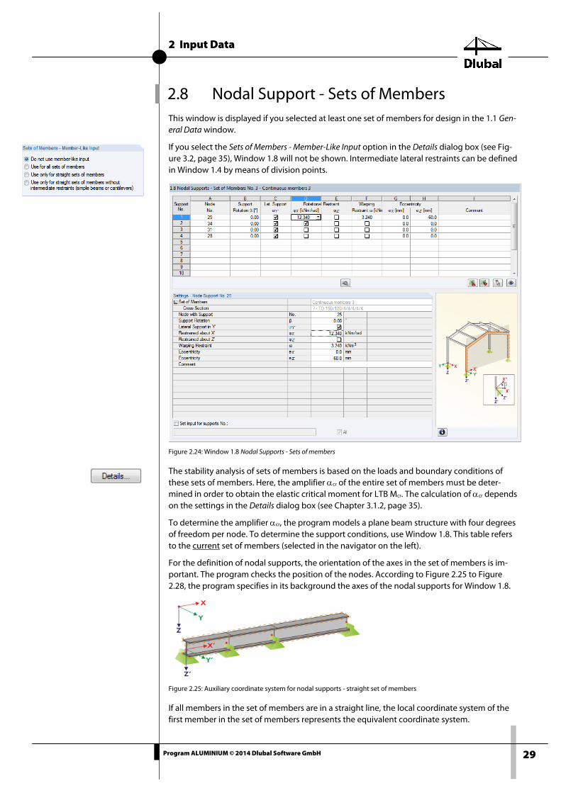
2.8 Nodal Support - Sets of Members This window is displayed if you selected at least one set of members for design in the 1.1 Gen-eral Data window.
If you select the Sets of Members - Member-Like Input option in the Details dialog box (see Fig-ure 3.2, page 35), Window 1.8 will not be shown. Intermediate lateral restraints can be defined in Window 1.4 by means of division points.
Figure 2.24: Window 1.8 Nodal Supports - Sets of members
The stability analysis of sets of members is based on the loads and boundary conditions of these sets of members. Here, the amplifier αcr of the entire set of members must be deter-mined in order to obtain the elastic critical moment for LTB Mcr. The calculation of αcr depends on the settings in the Details dialog box (see Chapter 3.1.2, page 35).
To determine the amplifier αcr, the program models a plane beam structure with four degrees of freedom per node. To determine the support conditions, use Window 1.8. This table refers to the current set of members (selected in the navigator on the left).
For the definition of nodal supports, the orientation of the axes in the set of members is im-portant. The program checks the position of the nodes. According to Figure 2.25 to Figure 2.28, the program specifies in its background the axes of the nodal supports for Window 1.8.
Figure 2.25: Auxiliary coordinate system for nodal supports - straight set of members
If all members in the set of members are in a straight line, the local coordinate system of the first member in the set of members represents the equivalent coordinate system.

2 Input Data
30 Program ALUMINIUM © 2014 Dlubal Software GmbH
Figure 2.26: Auxiliary coordinate system for nodal supports - set of members in vertical plane
Even if the members of a set of members are not in a straight line, they still must lie in one plane. In Figure 2.26, it is a vertical plane. In this case, the X'-axis is horizontal and orientated in the direction of the plane. The Y'-axis is also defined as horizontal and perpendicular to the X'-axis. The Z'-axis is orientated perpendicularly downwards.
Figure 2.27: Auxiliary coordinate system for nodal supports - set of members in horizontal plane
If the members of the buckled set of members lie in a horizontal plane, the X'-axis runs parallel to the X-axis of the global coordinate system. The Y'-axis thus runs in the opposite direction to the global Z-axis, while the Z'-axis runs parallel to the global Y-axis.
Figure 2.28: Auxiliary coordinate system for nodal support – set of members in an inclined plane
Figure 2.28 shows the general case of a buckled set of members: The members lie not on a straight line but on an inclined plane. The definition of the X'-axis results from the intersection line between an inclined plane and the horizontal plane. The Y'-axis runs perpendicular to the X'-axis and perpendicular to the inclined plane. The Z'-axis is defined as rectangular to the X'- and Y'-axis.

2 Input Data
31 Program ALUMINIUM © 2014 Dlubal Software GmbH
2.9 Member End Releases - Sets of Members This window is displayed if you select at least one set of members in the 1.1 General Data win-dow for design. In this window, you can define releases for members in a set of members, which, for structural reasons, do not transfer the degrees of freedom restrained in Window 1.8 as internal forces. This table does not refer to the current set of members (selected in the navi-gator on the left).
If in the Details dialog box (see Figure 3.2, page 35) you select the Member-Like Input, Window 1.9 will not be shown. You can then define the intermediate lateral restraints by means of divi-sion points in Window 1.4.
Figure 2.29: Window 1.9 Member End Releases - Sets of members
In column B, you specify, at which Member Side (member end) the release exits or if both mem-ber sides are internally hinged.
In the columns C through F, you can define releases or spring constants in order to align the set of members model with the support conditions in Window 1.8.
2 Input Data
32 Program ALUMINIUM © 2014 Dlubal Software GmbH
2.10 Serviceability Data
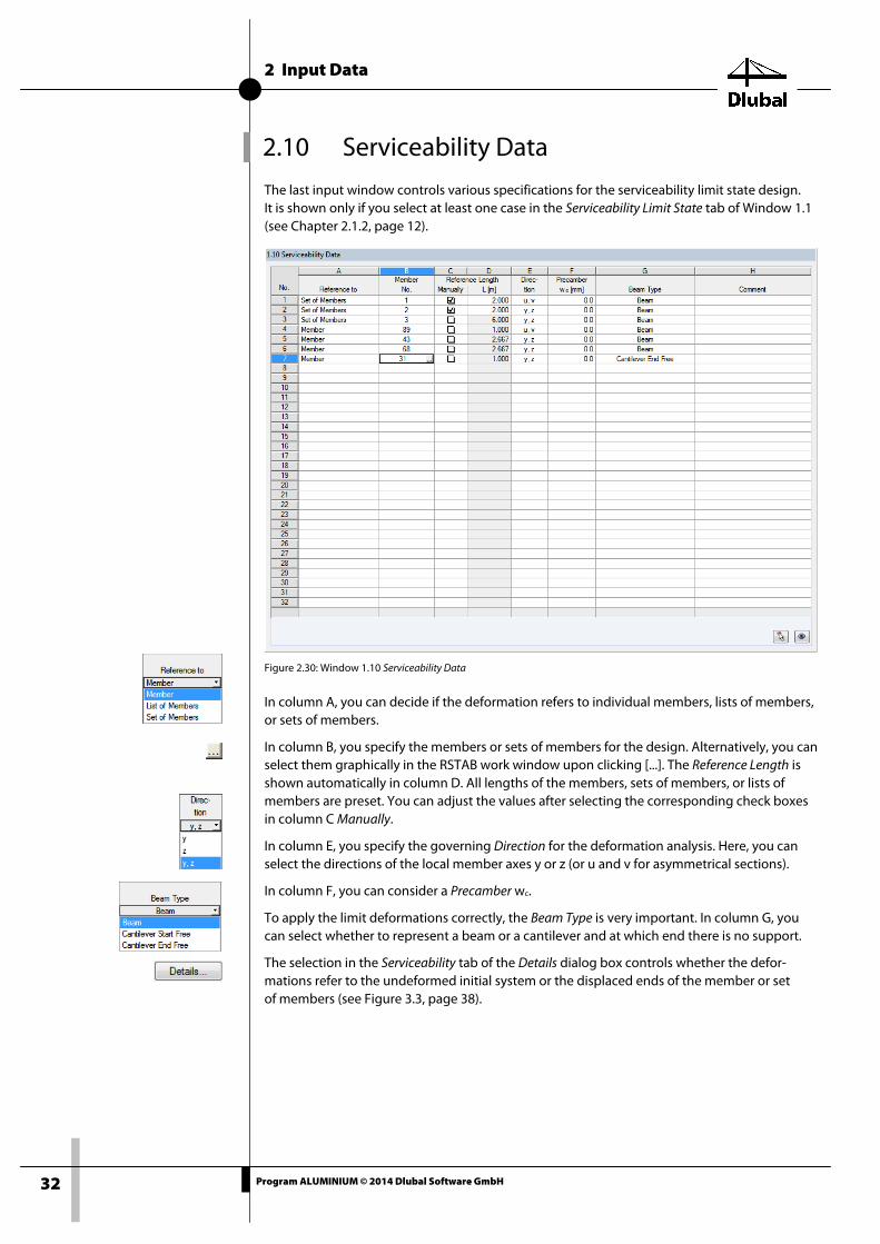
The last input window controls various specifications for the serviceability limit state design. It is shown only if you select at least one case in the Serviceability Limit State tab of Window 1.1 (see Chapter 2.1.2, page 12).
Figure 2.30: Window 1.10 Serviceability Data
In column A, you can decide if the deformation refers to individual members, lists of members, or sets of members.
In column B, you specify the members or sets of members for the design. Alternatively, you can select them graphically in the RSTAB work window upon clicking [...]. The Reference Length is shown automatically in column D. All lengths of the members, sets of members, or lists of members are preset. You can adjust the values after selecting the corresponding check boxes in column C Manually.
In column E, you specify the governing Direction for the deformation analysis. Here, you can select the directions of the local member axes y or z (or u and v for asymmetrical sections).
In column F, you can consider a Precamber wc.
To apply the limit deformations correctly, the Beam Type is very important. In column G, you can select whether to represent a beam or a cantilever and at which end there is no support.
The selection in the Serviceability tab of the Details dialog box controls whether the defor-mations refer to the undeformed initial system or the displaced ends of the member or set of members (see Figure 3.3, page 38).

3 Calculation
33 Program ALUMINIUM © 2014 Dlubal Software GmbH
3. Calculation
3.1 Detail Settings Before starting the [Calculation], check the design details. To open the corresponding dialog box, you can use the [Details] button available in every window of the add-on module.
The Details dialog box contains the following tabs:
• Ultimate Limit State
• Stability
• Serviceability
• Other
3.1.1 Ultimate Limit State
Figure 3.1: Dialog box Details, tab Ultimate Limit State
Alternative Values This section lists factors that can be determined differently according to EN 1999-1-1. If a check box is selected, the standard value is used. The corresponding clauses from the standard are given.
To select all or clear the selection of all check boxes, click the [(Un)select All] button.
Options In ALUMINIUM, cross-sections assigned to class 1 or 2 are designed plastically. If you do not want this to happen, you can set the Elastic design also for these cross-section classes.
An elastic shear design is possible so that the shear force check is not only performed on the basis of plastic shear resistance (default setting), but the shear stress analysis is performed, too.

3 Calculation
34 Program ALUMINIUM © 2014 Dlubal Software GmbH
You can activate the elastic design of angle sections to design them according to [1], Clauses 6.2.5 through 6.2.10 with the stresses instead of the resistance values (default setting). The fac-tors ξ0, η0, γ0 and ω0 are taken as 1.00.
Optionally, you can also perform an elastic design of general cross-sections based on stresses according to [1], Clauses 6.2.5 through 6.2.10. This covers some cross-sections from the RSTAB library or from SHAPE-THIN. In this case, the design is based not on the resistances (default set-ting) but on the stresses. Furthermore, you can activate the design of general cross-sections ac-cording to 6.2.1(5). For this, the yielding stresses according to VON MISES are calculated in every stress point. The greatest design ratio according to [1], Eq. (6.15) is then used to determine the governing stress point and the final design ratio for each x-location of the member. The pa-rameter C can be set in the National Annex Settings dialog box (see Chapter 2.1.3, page 13).
The Design of plate girders according to 6.7 is appropriate for cross-sections that fulfill the re-quirements of a plate girder and that are not indicated as "general" sections. However, ALU-MINIUM does not design longitudinal and transverse stiffeners.
The Shear design of solid cross-sections option allows you to check the shear and bending of solid sections. If you clear the selection, the bending moments, torsional moment, and shear forces are neglected, even if they were calculated in RSTAB.
In case of a Shear buckling design of webs, the designs are carried out according to [1], Clause 6.5.5 and 6.7.4.
The partial safety factors γM of the materials are managed in the National Annex Settings dialog box (see Chapter 2.1.3, page 13).
Classification of Cross-Sections For sections with SHAPE-THIN arc elements, the width-to-thickness ratios can result in classifi-cation problems, because ALUMINIUM considers only unreinforced cross-section parts (see [1], Figure 6.1 (a)). By selecting the Ignore classification of curved parts check box, you exclude short fillet curves from the classification if the user-defined c/t-ratio is not reached. Longitudinal stiffening ribs, edge lips, or bulbs have no influence on the designs.
By default, the check box Separately classify the load components acc. to 6.3.3 NOTE 1 and NOTE 2 is selected. If necessary, you can clear this default setting.
Transverse Welds If segments of members are welded to each other, the transverse welds lead to a softening in the heat-affected zone (HAZ). To consider the reduced strength according to [1], Clause 6.1.6.2, NOTE 2, you can choose one of two options: For the Reduced stress method, the fo,haz and fu,haz strength values are reduced according to [1], Table 3.2. The Effective cross-section method, on the other hand, uses reduced cross-section values for the designs (Surface A, elastic moduli W, moments of inertia I).
You can specify the parameters of the transverse welds in the 1.5 Transverse Welds window.

3 Calculation
35 Program ALUMINIUM © 2014 Dlubal Software GmbH
3.1.2 Stability
Figure 3.2: Dialog box Details, tab Stability
Stability Analysis The Perform stability analysis check box is available if, in addition to the cross-section checks, you also want to run a stability analysis. If you clear the check box, the Windows 1.4 through 1.9 are not shown.
If you select this check box, you can specify the axes that are relevant for the flexural buckling analysis. In addition, you can Include second-order effects according to [1], Clause 5.2.2 (4) with a manually definable factor for bending moments. For example for a frame, whose governing buckling mode is lateral deflection, you can thus determine the internal forces according to the geometrically linear static analysis and increase them by using the appropriate factors. In-creasing the bending moments has no effect on the check for flexural buckling resistance ac-cording to [1], Clause 6.3.1.
Determination of Elastic Critical Moment for LTB The elastic critical moment is determined according to the default setting Automatically by Eigenvalue Method. The program uses a finite member model to determine Mcr under consid-eration of the following points:
• Dimensions of gross cross-section
• Load type and position of load application point
• Actual moment distribution
• Lateral restraints (from support conditions)
• Actual boundary conditions
The degrees of freedom can be controlled by using the factors kz and kw (see Chapter 2.6, page 26).
3 Calculation
36 Program ALUMINIUM © 2014 Dlubal Software GmbH
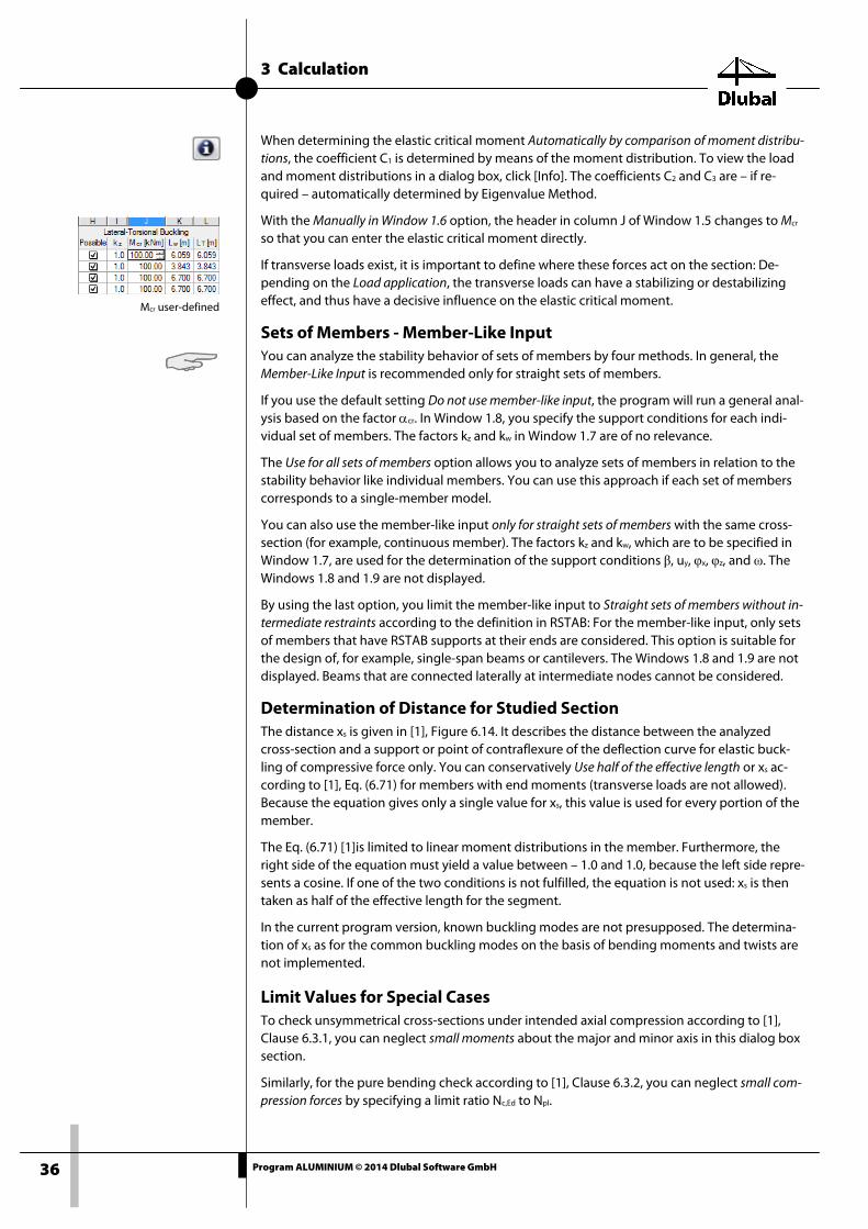
Mcr user-defined
When determining the elastic critical moment Automatically by comparison of moment distribu-tions, the coefficient C1 is determined by means of the moment distribution. To view the load and moment distributions in a dialog box, click [Info]. The coefficients C2 and C3 are – if re-quired – automatically determined by Eigenvalue Method.
With the Manually in Window 1.6 option, the header in column J of Window 1.5 changes to Mcr so that you can enter the elastic critical moment directly.
If transverse loads exist, it is important to define where these forces act on the section: De-pending on the Load application, the transverse loads can have a stabilizing or destabilizing effect, and thus have a decisive influence on the elastic critical moment.
Sets of Members - Member-Like Input You can analyze the stability behavior of sets of members by four methods. In general, the Member-Like Input is recommended only for straight sets of members.
If you use the default setting Do not use member-like input, the program will run a general anal-ysis based on the factor αcr. In Window 1.8, you specify the support conditions for each indi-vidual set of members. The factors kz and kw in Window 1.7 are of no relevance.
The Use for all sets of members option allows you to analyze sets of members in relation to the stability behavior like individual members. You can use this approach if each set of members corresponds to a single-member model.
You can also use the member-like input only for straight sets of members with the same cross-section (for example, continuous member). The factors kz and kw, which are to be specified in Window 1.7, are used for the determination of the support conditions β, uy, φx, φz, and ω. The Windows 1.8 and 1.9 are not displayed.
By using the last option, you limit the member-like input to Straight sets of members without in-termediate restraints according to the definition in RSTAB: For the member-like input, only sets of members that have RSTAB supports at their ends are considered. This option is suitable for the design of, for example, single-span beams or cantilevers. The Windows 1.8 and 1.9 are not displayed. Beams that are connected laterally at intermediate nodes cannot be considered.
Determination of Distance for Studied Section The distance xs is given in [1], Figure 6.14. It describes the distance between the analyzed cross-section and a support or point of contraflexure of the deflection curve for elastic buck-ling of compressive force only. You can conservatively Use half of the effective length or xs ac-cording to [1], Eq. (6.71) for members with end moments (transverse loads are not allowed). Because the equation gives only a single value for xs, this value is used for every portion of the member.
The Eq. (6.71) [1]is limited to linear moment distributions in the member. Furthermore, the right side of the equation must yield a value between – 1.0 and 1.0, because the left side repre-sents a cosine. If one of the two conditions is not fulfilled, the equation is not used: xs is then taken as half of the effective length for the segment.
In the current program version, known buckling modes are not presupposed. The determina-tion of xs as for the common buckling modes on the basis of bending moments and twists are not implemented.
Limit Values for Special Cases To check unsymmetrical cross-sections under intended axial compression according to [1], Clause 6.3.1, you can neglect small moments about the major and minor axis in this dialog box section.
Similarly, for the pure bending check according to [1], Clause 6.3.2, you can neglect small com-pression forces by specifying a limit ratio Nc,Ed to Npl.

3 Calculation
37 Program ALUMINIUM © 2014 Dlubal Software GmbH
Intended Torsion is not clearly specified in EN 1999-1-1. If there is torsion not exceeding the de-fault shear stress ratio of 5 %, it is neglected in the stability analysis; results for the flexural and torsional-flexural buckling are shown.
If one of the limits is exceed in this section, a message appears in the results window. No stabil-ity analysis is run. The cross-section checks are run independent from this. These limit settings are not part of the EN 1999-1-1 or a National Annex. Changing the limits is within the user’s re-sponsibility.
Slenderness Determination Annex I of EN 1999-1-1 provides alternative simplified methods for the calculation of the rela-tive slendernesses for torsional-flexural buckling without axial force (Annex I.2, clause 2) as well as torsional and torsional-flexural buckling with axial force (Annex I.4, section 2). You can activate these alternative methods by selecting the corresponding check boxes.
The relative slendernesses of unequal angles, back-to-back-angles, cruciforms, sections with fillet welds and bulbs, as well as general sections are never determined according to the alter-native methods.
Torsional and Torsional-Flexural Buckling Clause 6.3.1.4(1) gives cross-section types for which the check of torsional and torsional-flexural buckling may be ignored: hollow sections, doubly-symmetric I-sections, and sections composed of radiating outstands (angles, tees) that are classified as class 1 and 2. The check box allows you to perform stability analyses for such sections nonetheless – except for hollow sections which are generally excluded from the stability design.

3 Calculation
38 Program ALUMINIUM © 2014 Dlubal Software GmbH
3.1.3 Serviceability
Figure 3.3: Dialog box Details, tab Serviceability
Deformation Relative To By using the options in this dialog box section, you can decide whether to refer the maximum deformations to the Shifted member ends / set of members ends (connecting line between start and end node of the deformed system) or to the Undeformed initial system. Usually, the defor-mations are to be checked relative to the displacements in the global analysis.
You can check the limit deformations in the National Annex Settings dialog box and, if neces-sary, adjust them (see Figure 2.9, page 13).

3 Calculation
39 Program ALUMINIUM © 2014 Dlubal Software GmbH
3.1.4 Other
Figure 3.4: Dialog box Details, tab Other
Cross-Section Optimization The optimization is targeted on the maximum design ratio of 100 %. If necessary, you can also specify a different upper limit in the text box.
Check of Member Slendernesses In the two text boxes, you can specify the limit values λlimit to control the member slenderness-es. You can make separate specifications for members with pure tension and for members with bending and compression.
In Window 3.3, the limit values are compared with the actual member slendernesses. To dis-play this window after the calculation (see Chapter 4.8, page 49), select the corresponding check box in the Display Result Windows dialog box section.
Cross-Section Database In ALUMINIUM, you can also design sections that actually consist of steel (rolled sections). If you clear the selection, only cross-sections of the categories Parametric - Thin-Walled, Parametric - Massive, or User-Defined Sections are designed.
Settings of SHAPE-THIN Cross-Sections This check box ensures that the cross-section is symmetric relative to the principal axis system. Some SHAPE-THIN sections or general RSTAB sections do not, among other things, meet the requirements of the ALUMINIUM design routine, because the y-axis is always assumed as ma-jor and the z-axis as minor axis. If, for example, Iy < Iz, or the rotation of the main axis shows that the z-axis represents the principal axis, the results of ALUMINIUM can result in misinter-pretations.

3 Calculation
40 Program ALUMINIUM © 2014 Dlubal Software GmbH
The check box allows you to check the symmetry of general sections, independent from the SHAPE-THIN analysis. If both methods yield different results, an error message appears.
For closed cross-sections, different proof strength and ultimate strengths than for open cross-sections apply (see [1], Table 3.2b). In addition, there are different design methods, for exam-ple according to [1], Clause 6.2.9.1 and 6.2.9.2. If the Bredt torsional constant It,Bredt component of the torsion constant It is greater than the specified value, the cross-section is taken as closed. In this case, you can also neglect the possibility of torsional and torsional-flexural buckling (see [1], Clause 6.3.1.4 NOTE).
The Internal divisions of cross-section elements has an influence on the calculation time for the determination of the cross-section properties. For Arc elements, you need to specify the angle in degrees [°].
Display Result Windows Here, you can select which results windows including parts list you want to display. These win-dows are described in Chapter 4 Results.
Window 3.3 Member Slendernesses is deactivated by default.

3 Calculation
41 Program ALUMINIUM © 2014 Dlubal Software GmbH
3.2 Start Calculation To start the calculation in ALUMINIUM, use the [Calculation] button available in every input window of the module.
ALUMINIUM searches for available results of the load cases, load combinations, and result combinations selected for design. If no results can be found, the program starts the RSTAB calculation to determine the design-relevant internal forces.
You can also start the calculation in the RSTAB user interface. To do this, use the To Calculate dialog box (menu Calculation → To Calculate), containing design cases as well as load cases or load combinations.
Figure 3.5: Dialog box To Calculate
If the ALUMINIUM cases are missing in the Not Calculated list, select All or Add-on Modules in the drop-down list at the end of the dialog box section.
To transfer the selected ALUMINIUM cases to the section on the right, click []. Click [OK] to start the calculation.
Alternatively, you can start the calculation of a design case by using the drop-down list in the toolbar. In this list, select the ALUMINIUM case, and then click [Show Results].
Figure 3.6: Direct calculation of an ALUMINIUM design case in RSTAB
Subsequently, you can observe the design process in a separate dialog box.
4 Results
42 Program ALUMINIUM © 2014 Dlubal Software GmbH
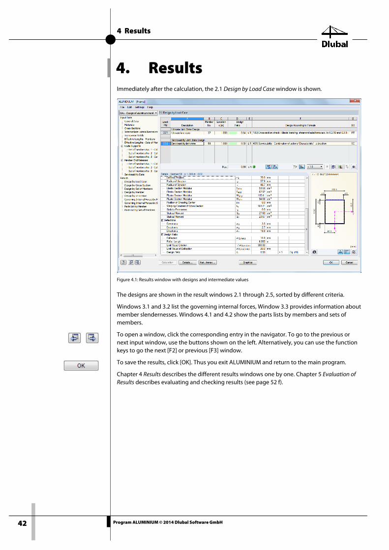
4. Results Immediately after the calculation, the 2.1 Design by Load Case window is shown.
Figure 4.1: Results window with designs and intermediate values
The designs are shown in the result windows 2.1 through 2.5, sorted by different criteria.
Windows 3.1 and 3.2 list the governing internal forces, Window 3.3 provides information about member slendernesses. Windows 4.1 and 4.2 show the parts lists by members and sets of members.
To open a window, click the corresponding entry in the navigator. To go to the previous or next input window, use the buttons shown on the left. Alternatively, you can use the function keys to go the next [F2] or previous [F3] window.
To save the results, click [OK]. Thus you exit ALUMINIUM and return to the main program.
Chapter 4 Results describes the different results windows one by one. Chapter 5 Evaluation of Results describes evaluating and checking results (see page 52 f).
4 Results
43 Program ALUMINIUM © 2014 Dlubal Software GmbH
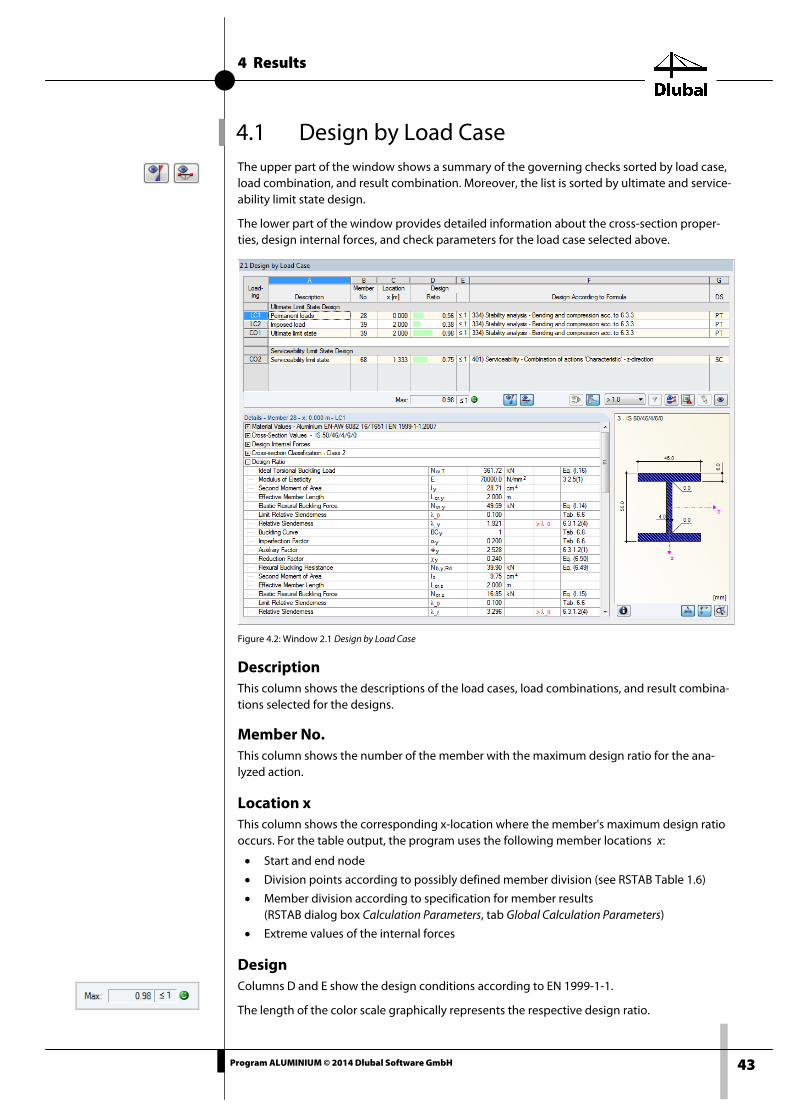
4.1 Design by Load Case The upper part of the window shows a summary of the governing checks sorted by load case, load combination, and result combination. Moreover, the list is sorted by ultimate and service-ability limit state design.
The lower part of the window provides detailed information about the cross-section proper-ties, design internal forces, and check parameters for the load case selected above.
Figure 4.2: Window 2.1 Design by Load Case
Description This column shows the descriptions of the load cases, load combinations, and result combina-tions selected for the designs.
Member No. This column shows the number of the member with the maximum design ratio for the ana-lyzed action.
Location x This column shows the corresponding x-location where the member's maximum design ratio occurs. For the table output, the program uses the following member locations x:
• Start and end node
• Division points according to possibly defined member division (see RSTAB Table 1.6)
• Member division according to specification for member results (RSTAB dialog box Calculation Parameters, tab Global Calculation Parameters)
• Extreme values of the internal forces
Design Columns D and E show the design conditions according to EN 1999-1-1.
The length of the color scale graphically represents the respective design ratio.
4 Results
44 Program ALUMINIUM © 2014 Dlubal Software GmbH
Design According to Formula This column shows the equations of the standard used in the checks.
DS The last column provides information about the relevant design situations (DS): PT or AC for the ultimate limit state or one of the three design situations for the serviceability limit state (SC, SF, SQ) according to the specifications in the 1.1 General Data window (see Figure 2.7, page 12).
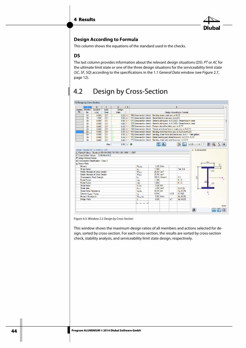
4.2 Design by Cross-Section
Figure 4.3: Window 2.2 Design by Cross-Section
This window shows the maximum design ratios of all members and actions selected for de-sign, sorted by cross-section. For each cross-section, the results are sorted by cross-section check, stability analysis, and serviceability limit state design, respectively.

4 Results
45 Program ALUMINIUM © 2014 Dlubal Software GmbH
4.3 Design by Set of Members
Figure 4.4: Window 2.3 Design by Set of Members
This results window is displayed if you have selected at least one set of members for design. The window lists the maximum design ratios sorted by set of members.
The Member No. column shows the number of the one member within the set of members that bears the maximum ratio for the respective design criterion.
The output by set of members clearly presents the design for an entire structural group (for example, a frame).
4 Results
46 Program ALUMINIUM © 2014 Dlubal Software GmbH
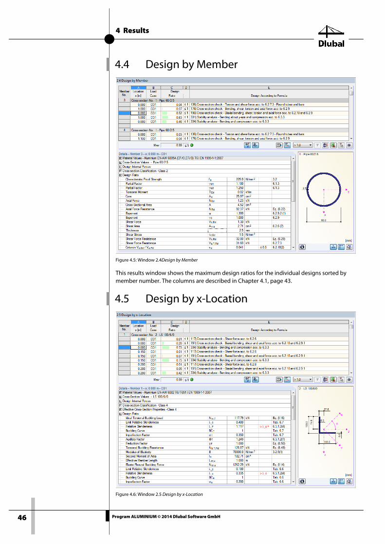
4.4 Design by Member
Figure 4.5: Window 2.4Design by Member
This results window shows the maximum design ratios for the individual designs sorted by member number. The columns are described in Chapter 4.1, page 43.
4.5 Design by x-Location
Figure 4.6: Window 2.5 Design by x-Location
4 Results
47 Program ALUMINIUM © 2014 Dlubal Software GmbH
This results window lists the maxima for each member at the locations x resulting from the division points in RSTAB:
• Start and end node
• Division points according to possibly defined member division (see RSTAB Table 1.6)
• Member division according to specification for member results (RSTAB dialog box Calculation Parameters, tab Global Calculation Parameters)
• Extreme values of the internal forces
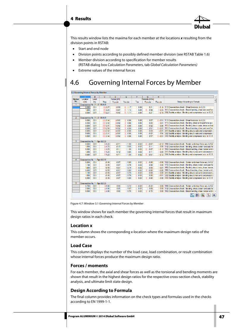
4.6 Governing Internal Forces by Member
Figure 4.7: Window 3.1 Governing Internal Forces by Member
This window shows for each member the governing internal forces that result in maximum design ratios in each check.
Location x This column shows the corresponding x-location where the maximum design ratio of the member occurs.
Load Case This column displays the number of the load case, load combination, or result combination whose internal forces produce the maximum design ratio.
Forces / moments For each member, the axial and shear forces as well as the torsional and bending moments are shown that result in the highest design ratios for the respective cross-section check, stability analysis, and ultimate limit state design.
Design According to Formula The final column provides information on the check types and formulas used in the checks according to EN 1999-1-1.

4 Results
48 Program ALUMINIUM © 2014 Dlubal Software GmbH
4.7 Governing Internal Forces by Set of Members
Figure 4.8: Window 3.2 Governing Internal Forces by Set of Members
This window shows the internal forces that result in the maximum design ratios in the design of each set of members.
4 Results
49 Program ALUMINIUM © 2014 Dlubal Software GmbH
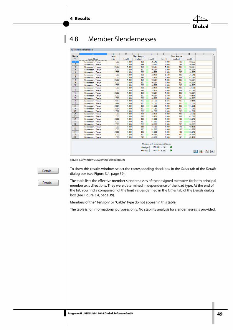
4.8 Member Slendernesses
Figure 4.9: Window 3.3 Member Slendernesses
To show this results window, select the corresponding check box in the Other tab of the Details dialog box (see Figure 3.4, page 39).
The table lists the effective member slendernesses of the designed members for both principal member axis directions. They were determined in dependence of the load type. At the end of the list, you find a comparison of the limit values defined in the Other tab of the Details dialog box (see Figure 3.4, page 39).
Members of the "Tension" or "Cable" type do not appear in this table.
The table is for informational purposes only. No stability analysis for slendernesses is provided.

4 Results
50 Program ALUMINIUM © 2014 Dlubal Software GmbH
4.9 Parts List by Member Finally, ALUMINIUM provides a summary of all cross-sections used in the design case.
Figure 4.10: Window 4.1 Parts List by Member
By default, this list contains only the designed members. If you need a parts list for all members of the model, select the corresponding option in the Other tab of the Details dialog box (see Figure 3.4, page 39).
Part No. The program automatically assigns part numbers to similar members.
Cross-Section Description This column shows the cross-section numbers and descriptions.
Number of Members This column shows for each part how many similar members are used.
Length This column displays the length of a single member.
Total Length This column shows the product determined from the previous two columns.
Surface Area For each part, the program indicates the surface area relative to the total length. The surface area is determined from the Surface of the cross-sections that can be seen in Windows 1.3 and 2.1 through 2.5 in the cross-section properties (see Figure 2.16, page 19).

4 Results
51 Program ALUMINIUM © 2014 Dlubal Software GmbH
Volume The volume of a part is determined from the cross-sectional area and the total length.
Unit Weight The Unit Weight is the weight of the section relative to the length of one meter.
Weight The values of this column are determined from the respective product of the entries in columns C and G.
Total Weight The final column indicates the total weight of each part.
Sum At the bottom of the list, you find a summary of the values in the columns B, D, E, F, and I. The last cell of the Total Weight column informs you about the total amount of steel required.
4.10 Parts List by Set of Members
Figure 4.11: Window 4.2 Parts List by Set of Members
The final results window is displayed if you have selected at least one set of members for de-sign. It summarizes entire structural groups (for example, a horizontal beam) in a parts list.
The columns are described in the previous chapter. If different cross-sections are used in the set of members, the program averages the surface area, volume, and cross-section weight.

5 Evaluation of Results
52 Program ALUMINIUM © 2014 Dlubal Software GmbH
5. Evaluation of Results You can evaluate the design results in different ways. The buttons below the upper table can be helpful.
Figure 5.1: Button for evaluation of results
The buttons have the following functions:
Button Description Function
Ultimate limit state Shows or hides the results of the ultimate limit state design
Serviceability limit state
Shows or hides the results of the serviceability limit state design
Result combination Creates a new result combination from the governing load cases and load combinations
Color bars Shows or hides the colored reference scales in the results windows
Filter parameters Gives the criterion for filtering the tables: ratios greater than 1, maximum value, or user-defined limit
Apply filter Shows only rows with selected filter parameter (ratio > 1, maximum, user-defined limit)
Result diagrams Opens the dialog box Result Diagram on Member Chapter 5.2, page 55
Excel export Exports the table to MS Excel / OpenOffice Chapter 7.4.3, page 66
5 Evaluation of Results
53 Program ALUMINIUM © 2014 Dlubal Software GmbH
Member selection Allows for the graphical selection of a member to dis-play its results in the table
View mode Goes to the RSTAB work window for changing the view
Table 5.1: Buttons in the Windows 2.1 through 2.5
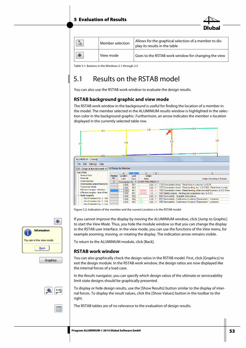
5.1 Results on the RSTAB model You can also use the RSTAB work window to evaluate the design results.
RSTAB background graphic and view mode The RSTAB work window in the background is useful for finding the location of a member in the model. The member selected in the ALUMINIUM results window is highlighted in the selec-tion color in the background graphic. Furthermore, an arrow indicates the member x-location displayed in the currently selected table row.
Figure 5.2: Indication of the member and the current Location x in the RSTAB model
If you cannot improve the display by moving the ALUMINIUM window, click [Jump to Graphic] to start the View Mode. Thus, you hide the module window so that you can change the display in the RSTAB user interface. In the view mode, you can use the functions of the View menu, for example zooming, moving, or rotating the display. The indication arrow remains visible.
To return to the ALUMINIUM module, click [Back].
RSTAB work window You can also graphically check the design ratios in the RSTAB model. First, click [Graphics] to exit the design module. In the RSTAB work window, the design ratios are now displayed like the internal forces of a load case.
In the Results navigator, you can specify which design ratios of the ultimate or serviceability limit state designs should be graphically presented.
To display or hide design results, use the [Show Results] button similar to the display of inter-nal forces. To display the result values, click the [Show Values] button in the toolbar to the right.
The RSTAB tables are of no relevance to the evaluation of design results.

5 Evaluation of Results
54 Program ALUMINIUM © 2014 Dlubal Software GmbH
To set the design cases, you can use the list in the toolbar.
To adjust the results display, use the Display navigator below the entry Results → Members. The display of the design ratios is Two-Colored by default.
Figure 5.3: Display navigator: Results → Members
When you select a multicolor representation (options With/Without Diagram or Cross-Sections), the color panel becomes available. It provides the common control functions described in the RSTAB manual, Chapter 3.4.6.
Figure 5.4: Design ratios with display option Without Diagram
You can include the design result graphics in the printout report (see Chapter 6.2, page 58).
To return to the add-on module, click [ALUMINIUM] in the panel.

5 Evaluation of Results
55 Program ALUMINIUM © 2014 Dlubal Software GmbH
5.2 Result diagrams You can also graphically evaluate the result distributions of a member in the result diagram.
To do this, select the member (or set of members) in the ALUMINIUM results window by click-ing in the corresponding table row of the member. Then, open the Result Diagram on Member dialog box by clicking the button shown on the left. The button is located at the end of the upper table (see Figure 5.1, page 52).
To display the result diagrams, select in the RSTAB menu
Results → Result Diagrams for Selected Members
or use the button in the RSTAB toolbar shown on the left.
A window opens, graphically presenting the distribution of the maximum design values on the member or set of members.
Figure 5.5: Dialog box Result Diagram on Member
To select the relevant ALUMINIUM design case, use the drop-down list in the toolbar of the dialog box.
The Result Diagram on Member dialog box is described in the RSTAB manual, Chapter 9.5.
5 Evaluation of Results
56 Program ALUMINIUM © 2014 Dlubal Software GmbH
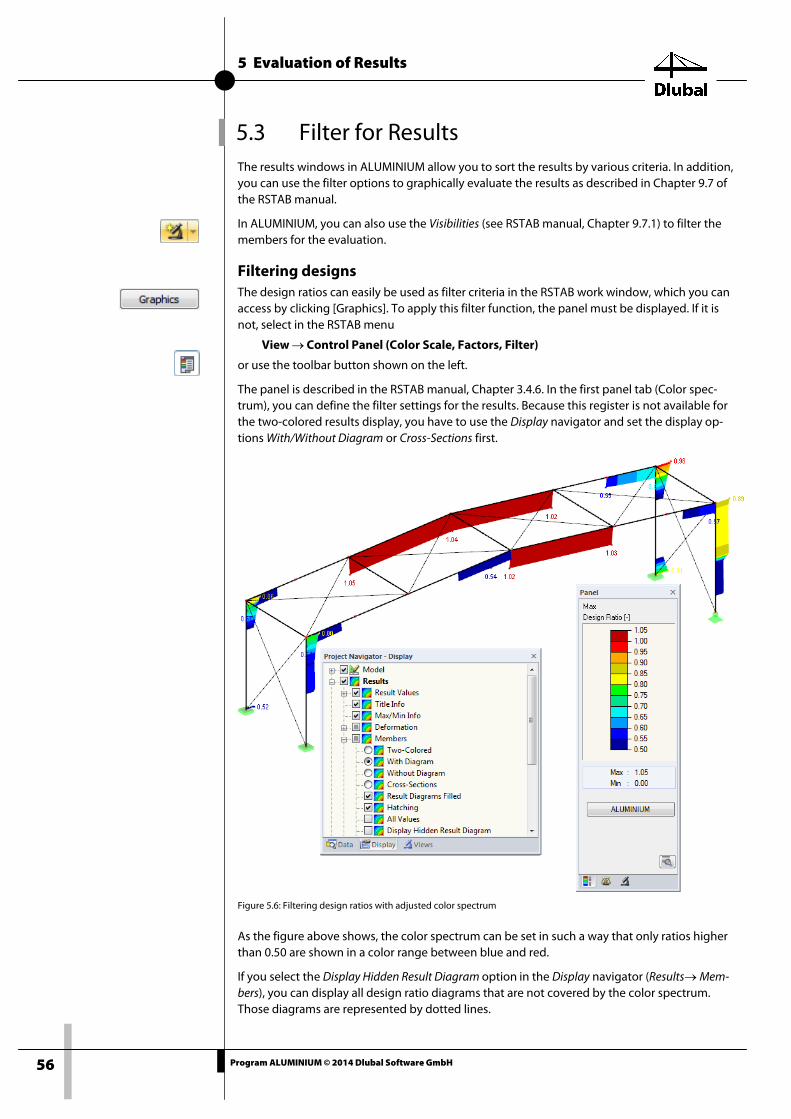
5.3 Filter for Results The results windows in ALUMINIUM allow you to sort the results by various criteria. In addition, you can use the filter options to graphically evaluate the results as described in Chapter 9.7 of the RSTAB manual.
In ALUMINIUM, you can also use the Visibilities (see RSTAB manual, Chapter 9.7.1) to filter the members for the evaluation.
Filtering designs The design ratios can easily be used as filter criteria in the RSTAB work window, which you can access by clicking [Graphics]. To apply this filter function, the panel must be displayed. If it is not, select in the RSTAB menu
View → Control Panel (Color Scale, Factors, Filter)
or use the toolbar button shown on the left.
The panel is described in the RSTAB manual, Chapter 3.4.6. In the first panel tab (Color spec-trum), you can define the filter settings for the results. Because this register is not available for the two-colored results display, you have to use the Display navigator and set the display op-tions With/Without Diagram or Cross-Sections first.
Figure 5.6: Filtering design ratios with adjusted color spectrum
As the figure above shows, the color spectrum can be set in such a way that only ratios higher than 0.50 are shown in a color range between blue and red.
If you select the Display Hidden Result Diagram option in the Display navigator (Results→ Mem-bers), you can display all design ratio diagrams that are not covered by the color spectrum. Those diagrams are represented by dotted lines.

5 Evaluation of Results
57 Program ALUMINIUM © 2014 Dlubal Software GmbH
Filtering members In the Filter tab of the control panel, you can specify the numbers of particular members to display their results exclusively, that is, filtered. This function is described in the RSTAB manual, Chapter 9.7.3.
Figure 5.7: Member filter for the design ratios of an edge beam
Unlike the partial view function (Visibilities), the graphic also displays the entire model. The figure above shows the design ratios in the edge beam of a container. The remaining members are displayed in the model but are shown without design ratios.

6 Printout
58 Program ALUMINIUM © 2014 Dlubal Software GmbH
6. Printout
6.1 Printout Report Like in RSTAB, the program generates a printout report for the ALUMINIUM results, to which you can add graphics and descriptions. The selection in the printout report determines which data from the design module will be included in the final printout.
The printout report is described in the RSTAB manual. In particular, Chapter 10.1.3.5 Selecting Data of Add-on Modules describes how to select input and output data from add-on modules for the printout report.
For large structural systems with many design cases, it is recommended to split the data into several printout reports, thus allowing for a clearly-arranged printout.
6.2 Graphic Printout In RSTAB, you can add every picture displayed in the work window to the printout report or send it directly to a printer. In this way, you can also prepare the design ratios displayed on the RSTAB model for the printout.
Printing graphics is described in the RSTAB manual, Chapter 10.2.
Designs on the RSTAB Model To print the current graphic of the design ratios, select in the menu
File → Print
or use the toolbar button shown on the left.
Figure 6.1: Button [Print Graphic] in RSTAB toolbar
Result diagrams In the Result Diagram on Member dialog box, you can also send the graphic with the design values to the report using the [Print] button. Furthermore, you can print the graphic directly.
Figure 6.2: Button Print Graphic in the dialog box Result Diagram on Member
The following dialog box appears.
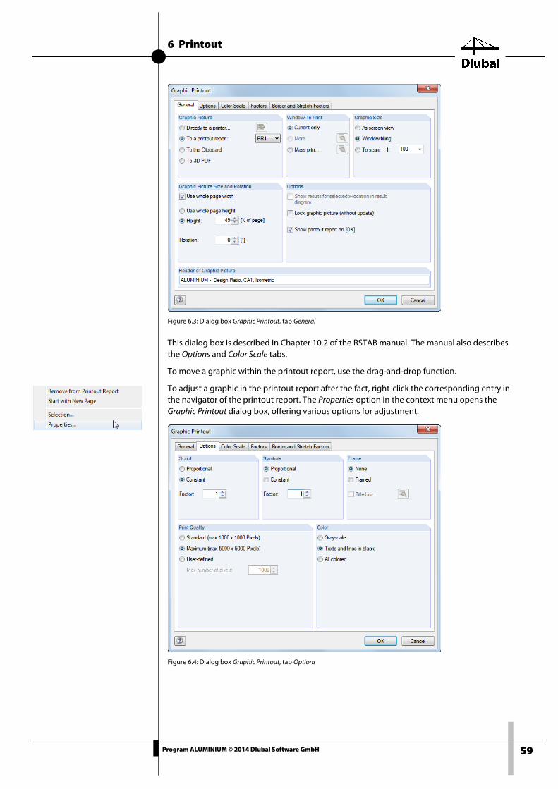
6 Printout
59 Program ALUMINIUM © 2014 Dlubal Software GmbH
Figure 6.3: Dialog box Graphic Printout, tab General
This dialog box is described in Chapter 10.2 of the RSTAB manual. The manual also describes the Options and Color Scale tabs.
To move a graphic within the printout report, use the drag-and-drop function.
To adjust a graphic in the printout report after the fact, right-click the corresponding entry in the navigator of the printout report. The Properties option in the context menu opens the Graphic Printout dialog box, offering various options for adjustment.
Figure 6.4: Dialog box Graphic Printout, tab Options

7 General Functions
60 Program ALUMINIUM © 2014 Dlubal Software GmbH
7. General Functions This chapter describes useful menu functions and export options for the designs.
7.1 Design Cases Design cases allow you to group members for the design. In this way, you can consider groups of structural components or analyze members with particular design specifications (for exam-ple, changed materials, partial safety factors, optimization).
It is no problem to analyze the same member or set of members in different design cases.
To calculate an ALUMINIUM design case, you can also use the load case list in the RSTAB toolbar.
Creating new design case To create a new design case, select in the ALUMINIUM menu
File → New Case.
The following dialog box appears:
Figure 7.1: Dialog box New ALUMINIUM Case
In this dialog box, enter a No. (one that is still available) for the new design case. An appropriate Description will make the selection in the load case list easier.
Now click [OK] to open the 1.1 General Data window of ALUMINIUM where you can enter the design data.
Renaming design case To change the description of a design case, select in the ALUMINIUM menu
File → Rename Case.
The following dialog box appears:
Figure 7.2: Dialog box Rename ALUMINIUM Case
In this dialog box, you can write a different Description as well as a different No. for the design case.

7 General Functions
61 Program ALUMINIUM © 2014 Dlubal Software GmbH
Copying design case To copy the input data of the current design case, select in the ALUMINIUM menu
File → Copy Case.
The following dialog box appears:
Figure 7.3: Dialog box Copy ALUMINIUM
Define the No. and, if necessary, a Description for the new case.
Deleting design case To delete design cases, select from the ALUMINIUM menu
File → Delete Case.
The following dialog box appears:
Figure 7.4: Dialog box Delete Case
First, select the design case in the Available Cases section. To delete the selected case, click [OK].
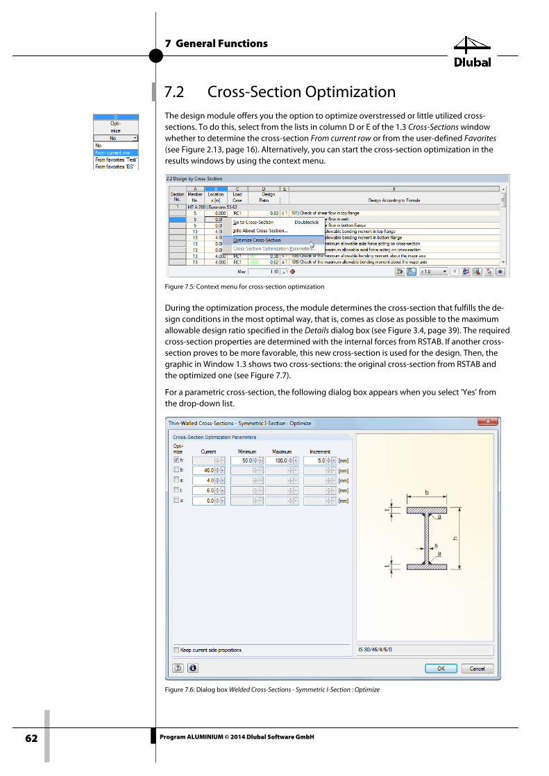
7 General Functions
62 Program ALUMINIUM © 2014 Dlubal Software GmbH
7.2 Cross-Section Optimization The design module offers you the option to optimize overstressed or little utilized cross-sections. To do this, select from the lists in column D or E of the 1.3 Cross-Sections window whether to determine the cross-section From current row or from the user-defined Favorites (see Figure 2.13, page 16). Alternatively, you can start the cross-section optimization in the results windows by using the context menu.
Figure 7.5: Context menu for cross-section optimization
During the optimization process, the module determines the cross-section that fulfills the de-sign conditions in the most optimal way, that is, comes as close as possible to the maximum allowable design ratio specified in the Details dialog box (see Figure 3.4, page 39). The required cross-section properties are determined with the internal forces from RSTAB. If another cross-section proves to be more favorable, this new cross-section is used for the design. Then, the graphic in Window 1.3 shows two cross-sections: the original cross-section from RSTAB and the optimized one (see Figure 7.7).
For a parametric cross-section, the following dialog box appears when you select 'Yes' from the drop-down list.
Figure 7.6: Dialog box Welded Cross-Sections - Symmetric I-Section : Optimize

7 General Functions
63 Program ALUMINIUM © 2014 Dlubal Software GmbH
By selecting the check boxes in the Optimize column, you decide which parameter(s) you want to modify. This enables the Minimum and Maximum columns, where you can specify the upper and lower limits of the parameter. The Increment column specifies the interval by which the dimensions of the parameter vary during the optimization process.
If you want to Keep current side proportions, select the corresponding check box. In addition, you must select at least two parameters for optimization.
Cross-sections built up from rolled cross-sections cannot be optimized.
Please note that the internal forces will not be recalculated automatically with the changed cross-sections in the optimization. It is up to you to decide which cross-sections you want to transfer to RSTAB for recalculation. Due to the changed stiffnesses in the structural system, the internal forces from the optimized cross-section may vary significantly. Therefore, it is recom-mended to recalculate the internal forces of the modified cross-section data after the first op-timization, and then to optimize the cross-sections once again.
You can export the modified cross-sections to RSTAB. To do this, go to the 1.3 Cross-Sections window, and then select in the menu
Edit → Export All Cross-Sections to RSTAB.
Alternatively, you can use the context menu in Window 1.3 to export optimized cross-sections to RSTAB.
Figure 7.7: Context menu in Window 1.3 Cross-Sections
Before the modified materials are transferred to RSTAB, a query appears as to whether you want to delete the results in RSTAB.
Figure 7.8: Query before export of modified cross-sections to RSTAB
After you confirm the query and start the [Calculation] in ALUMINIUM, the RSTAB internal forc-es and designs are determined in a single calculation run.
If the modified cross-sections are not exported to RSTAB, you can reimport the original cross-sections in the design module by using the options shown in Figure 7.7. Please note that this option is available in the 1.3 Cross-Sections window only.

7 General Functions
64 Program ALUMINIUM © 2014 Dlubal Software GmbH
7.3 Units and Decimal Places Units and decimal places for RSTAB and the add-on modules are managed in one common dialog box. To specify the units for ALUMINIUM, select on the module menu
Settings → Units and Decimal Places.
The dialog box known from RSTAB appears. In the Program / Module dialog box section, ALU-MINIUM is preset.
Figure 7.9: Dialog box Units and Decimal Places
To reuse the settings in other models, save them as a user-profile. The functions are described in the RSTAB manual, Chapter 11.1.3.

7 General Functions
65 Program ALUMINIUM © 2014 Dlubal Software GmbH
7.4 Data Exchange
7.4.1 Exporting Materials to RSTAB
If you adjusted the materials in ALUMINIUM for design, you can export the modified materials to RSTAB in a similar way as you export cross-sections. To do this, go to the 1.2 Materials win-dow, and then select in the menu
Edit → Export All Materials to RSTAB.
You can also export the changed materials to RSTAB by using the context menu in Window 1.2.
Figure 7.10: Context menu of Window 1.2 Materials
Before the modified materials are exported to RSTAB, a query appears as to whether you want to delete the results in RSTAB. After you confirm it and start the [Calculation] in ALUMINIUM, the RSTAB internal forces and designs are determined in a single calculation run.
If the modified materials are not exported to RSTAB, you can transfer the original materials to the design module, using the options shown in Figure 7.10. Please note, however, that this op-tion is available in the 1.2 Materials Window only.
7.4.2 Exporting Effective Lengths to RSTAB
If you adjusted the effective lengths in ALUMINIUM for design, you can export the modified ef-fective lengths to RSTAB. To do this, go to the 1.6 Effective Lengths - Members Window, and then select in the menu
Edit → Export All Effective Lengths to RSTAB.
You can also export the effective lengths to RSTAB by using the context menu in Window 1.6.
Figure 7.11: Context menu of Window 1.6 Effective Lengths - Members
Before the modified materials are transferred to RSTAB, a query appears as to whether you want to delete the results in RSTAB.
If the modified effective lengths are not exported to RSTAB, you can transfer the original effec-tive lengths to the design module, using the options shown in Figure 7.11. Please note that this option is available only in windows 1.6 Effective Lengths - Members and 1.7 Effective Lengths - Sets of Members.
7.4.3 Exporting Results
You can use the ALUMINIUM results also in other programs.
Clipboard To copy cells selected in the results windows to the Clipboard, press the keys [Ctrl]+[C]. To insert the cells, for example in a word processor, press [Ctrl]+[V]. The headers of the table columns are not transferred.

7 General Functions
66 Program ALUMINIUM © 2014 Dlubal Software GmbH
Printout report You can print the data of the ALUMINIUM module into the printout report (see Chapter 6.1, page 58) for export. Then, in the printout report, you can export them by selecting in the report menu
File → Export in RTF.
This function is described in the RSTAB manual, Chapter 10.1.11.
Excel / OpenOffice ALUMINIUM provides a function for the direct data export to MS Excel, OpenOffice.org Calc, or the file format CSV. To open the corresponding dialog box, select in the module menu
File → Export Tables.
The following dialog box appears.
Figure 7.12: Dialog box Export - MS Excel
Having selected the relevant options, you can start the export by clicking [OK]. Excel or OpenOffice are started automatically. You do not need to open the programs beforehand.
Figure 7.13: Results in Excel

8 Worked Example: Column Subject to Biaxial Bending
67 Program ALUMINIUM © 2014 Dlubal Software GmbH
8. Worked Example: Column Subject to Biaxial Bending
A stability analysis is performed for flexural buckling and torsional-flexural buckling of a column subject to biaxial bending, taking into account the interaction conditions.
8.1 Design values System and loading
Figure 8.1: System and design loads (γ-fold)
Internal forces according to first-order analysis
N My Mz Vy Vz
Figure 8.2: Internal forces
z
2 m
2 m
4 m F y
N
z
y
IS 300/120/5/10
q
Design values of the static loads
Nd = 16 kN
qz,d = 4 kN/m
Fy,d = 2 kN Cross-section: IS 300/120/5/10 Material: EN-AW 6005A (EP/O, ER/B) T6 Lengths: Lcr,y = 4 m
Lcr,z = 4 m
LW = 4 m
LT = 4 m

8 Worked Example: Column Subject to Biaxial Bending
68 Program ALUMINIUM © 2014 Dlubal Software GmbH
Design location (governing x-location)
The design is carried out for all x-locations (see Chapter 4.5) of the equivalent member. The governing location is at x = 2.00 m. RSTAB determines the following internal forces:
N = –16.00 kN My = 8.00 kNm Mz = 2.00 kNm Vy = 1.00 kN Vz = 0.00 kN
8.2 Cross-Section Properties
Cross-section property Symbol Value Unit
Cross-sectional area A 38.00 cm2
Moment of inertia Iy 5962.67 cm4
Moment of inertia Iz 288.29 cm4
Governing radius of gyration ry 12.53 cm
Governing radius of gyration rz 2.75 cm
Polar radius of gyration ro 12.83 cm
Weight wt 10.30 kg/m
Torsional constant J 8.79 cm4
Warping constant Iω 60552.00 cm6
Elastic section modulus Sy 397.51 cm3
Elastic section modulus Sz 48.05 cm3
Plastic section modulus Zy 446.00 cm3
Plastic section modulus Zz 73.75 cm3
Cross-section properties IS 300/120/5/10, EN-AW 6005A
8.3 Classification According to [1], Clause 6.3.3, NOTE 1 and NOTE 2, cross-sections with combined bending and longitudinal forces are to be classified separately for each load component. A cross-section can belong to different classes for shear force, bending about the major axis, and bending about the minor axis.
Slenderness parameters according to [1], Table 6.2 Buckling class BC for EN-AW 6005A: A (see [1], Table 3.2b)
Web - internal part
11s
1,s =εβ
16s
2,s =εβ
22s
3,s =εβ
Material properties for ts = 5 mm
MPa225f s,o = MPa270f s,u =
Material factor
054.1225/250f/250 s,os ===ε
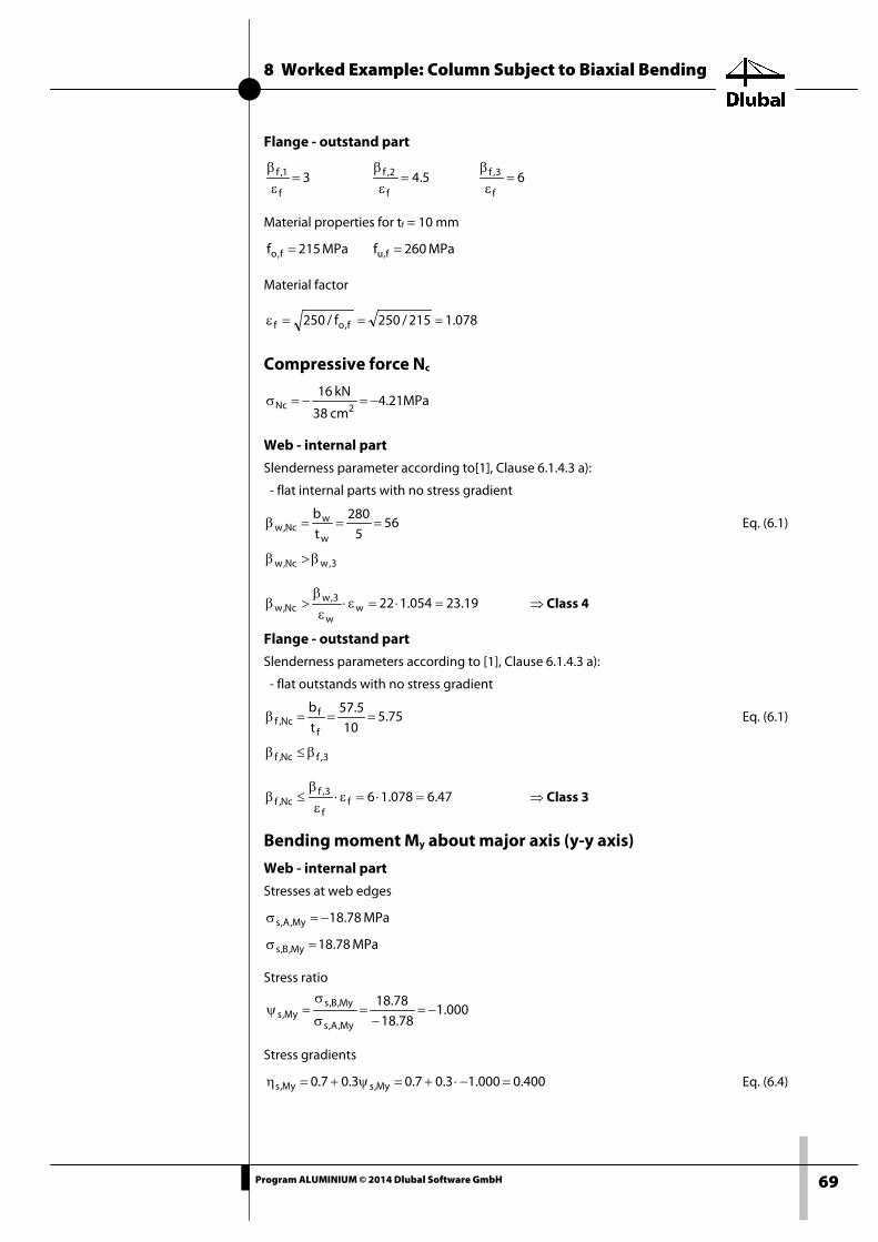
8 Worked Example: Column Subject to Biaxial Bending
69 Program ALUMINIUM © 2014 Dlubal Software GmbH
Flange - outstand part
3f
1,f =εβ
5.4f
2,f =εβ
6f
3,f =εβ
Material properties for tf = 10 mm
MPa215f f,o = MPa260f f,u =
Material factor
078.1215/250f/250 f,of ===ε
Compressive force Nc
MPa21.4cm38
kN162Nc −=−=σ
Web - internal part
Slenderness parameter according to[1], Clause 6.1.4.3 a):
- flat internal parts with no stress gradient
565
280t
b
w
wNc,w ===β Eq. (6.1)
3,wNc,w β>β
19.23054.122ww
3,wNc,w =⋅=ε⋅
εβ
>β ⇒ Class 4
Flange - outstand part
Slenderness parameters according to [1], Clause 6.1.4.3 a):
- flat outstands with no stress gradient
75.510
5.57t
b
f
fNc,f ===β Eq. (6.1)
3,fNc,f β≤β
47.6078.16ff
3,fNc,f =⋅=ε⋅
εβ
≤β ⇒ Class 3
Bending moment My about major axis (y-y axis)
Web - internal part
Stresses at web edges
MPa78.18My,A,s −=σ
MPa78.18My,B,s =σ
Stress ratio
000.178.18
78.18
My,A,s
My,B,sMy,s −=
−=
σ
σ=ψ
Stress gradients
400.0000.13.07.03.07.0 My,sMy,s =−⋅+=ψ+=η Eq. (6.4)
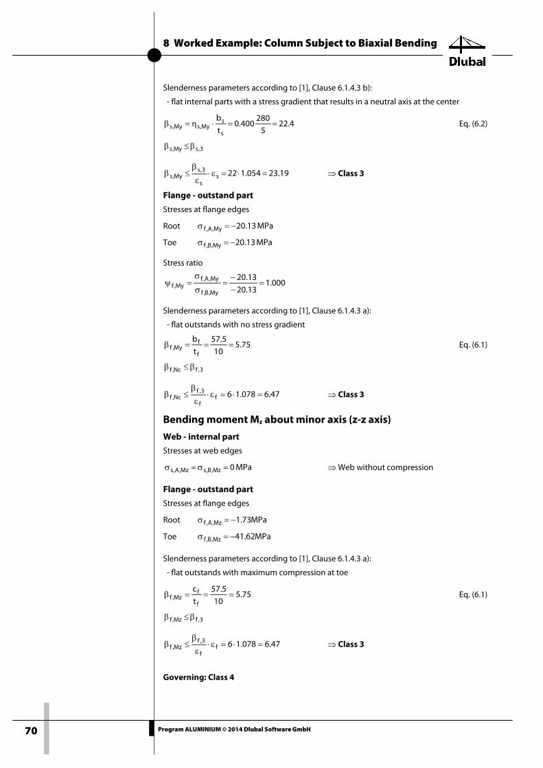
8 Worked Example: Column Subject to Biaxial Bending
70 Program ALUMINIUM © 2014 Dlubal Software GmbH
Slenderness parameters according to [1], Clause 6.1.4.3 b):
- flat internal parts with a stress gradient that results in a neutral axis at the center
4.225
280400.0
t
b
s
sMy,sMy,s ==⋅η=β Eq. (6.2)
3,sMy,s β≤β
19.23054.122ss
3,sMy,s =⋅=ε⋅
εβ
≤β ⇒ Class 3
Flange - outstand part
Stresses at flange edges
Root MPa13.20My,A,f −=σ
Toe MPa13.20My,B,f −=σ
Stress ratio
000.113.2013.20
My,B,f
My,A,fMy,f =
−−
=σ
σ=ψ
Slenderness parameters according to [1], Clause 6.1.4.3 a):
- flat outstands with no stress gradient
75.510
5.57t
b
f
fMy,f ===β Eq. (6.1)
3,fNc,f β≤β
47.6078.16ff
3,fNc,f =⋅=ε⋅
εβ
≤β ⇒ Class 3
Bending moment Mz about minor axis (z-z axis)
Web - internal part
Stresses at web edges
MPa0Mz,B,sMz,A,s =σ=σ ⇒ Web without compression
Flange - outstand part
Stresses at flange edges
Root MPa73.1Mz,A,f −=σ
Toe MPa62.41Mz,B,f −=σ
Slenderness parameters according to [1], Clause 6.1.4.3 a):
- flat outstands with maximum compression at toe
75.510
5.57t
c
f
fMz,f ===β Eq. (6.1)
3,fMz,f β≤β
47.6078.16ff
3,fMz,f =⋅=ε⋅
εβ
≤β ⇒ Class 3
Governing: Class 4

8 Worked Example: Column Subject to Biaxial Bending
71 Program ALUMINIUM © 2014 Dlubal Software GmbH
8.4 Effective Cross-Section Properties Effective cross-sectional area: Class 4 for compressive force Nc
Web - internal part
Buckling factor according to [1], Clause 6.1.5(2)
( ) ( ) ( ) ( )524.0
054.1/56
220054.1/56
32
/
C
/
C22
sNc,s
2
sNc,s
1Nc,s,c =−=
εβ−
εβ=ρ Eq. (6.12)
Effective web thickness
mm622.25524.0tt wNc,s,cNc,s,c =⋅=⋅ρ=
Effective web area
2sNc,s,cNc,eff,s mm16.734280622.2btA =⋅=⋅=
Flange - outstand part
Class 3 - no reduction according to clause 6.1.5(2), Eq. (6.11)
000.1Nc,f,c =ρ
mm10tt fNc,f,c ==
Flange area
2ff1,ff mm2400120102ct2A2A =⋅⋅=⋅⋅=⋅=
Effective area of true section
2fseff mm16.3134240016.734AAA =+=+=

8 Worked Example: Column Subject to Biaxial Bending
72 Program ALUMINIUM © 2014 Dlubal Software GmbH
8.5 Flexural Buckling About Major Axis (⊥ to y-y) Elastic torsional-flexural buckling force according to [1], Annex I.3
kN65.2574N25746524000
5962670070000
L
EIN
2
2
2y,cr
y2
y,cr ==⋅⋅π
=π
= Eq. (I.15)
Relative slenderness for flexural buckling according to [1], Clause 6.3.1.2(1)
512.02574652
2153800N
fA
y,cr
oy =
⋅=
⋅=λ Eq. (6.51)
Limit of the horizontal plateau and imperfection factor according to [1], Table 6.6
Buckling class A ⇒ 200.0y =α 100.00,y =λ
Conditions for considering buckling effects according to [1], Clause 6.3.1.2(4)
0,yy λ>λ 100.0512.0 >
y,cr2
0,yEd NN ⋅λ> 746.2565.2574010.016 =⋅>
Check
62.0746.2500.16
N
N
y,cr2
0,y
Edy,Ncr ==
⋅λ=η
After the second condition, it is not necessary to consider the flexural buckling about the y-axis.
Auxiliary factor according to clause 6.3.1.2(1)
( )[ ] ( )[ ] 672.0512.01.0512.02.015.015.0 22y0,yyyy =+−⋅+⋅=λ+λ−λ⋅α+⋅=φ Eq. (6.51)
Reduction factor according to clause 6.3.1.2(1)
903.0512.0672.0672.0
11222
y2yy
y =−+
=λ−φ+φ
=χ Eq. (6.50)
Results of the ALUMINIUM calculation
Moment of inertia Iy 5962.67 cm4
Effective member length Lcr,y 4.000 m
Elastic flexural-buckling force Ncr,y 2574.65 kN
Relative slenderness λtrans,y 0.512 > 0.1 6.3.1.2(4)
Buckling class Class A Tab. 3.2b
Imperfection factor αy 0.200 Tab. 6.6
Auxiliary factor φy 0.672 Eq. (6.51)
Reduction factor χy 0.903 Eq. (6.50)

8 Worked Example: Column Subject to Biaxial Bending
73 Program ALUMINIUM © 2014 Dlubal Software GmbH
8.6 Flexural Buckling About Minor Axis (⊥ to z-z) Elastic torsional-flexural buckling force according to [1], Annex I.3
kN483.124N1.1244834000
288292070000
L
EIN
2
2
2z,cr
z2
z,cr ==⋅⋅π
=π
= Eq. (I.15)
Relative slenderness for flexural buckling according to [1], Clause 6.3.1.2(1)
327.21.124483
2153800N
fA
z,cr
oz =
⋅=
⋅=λ Eq. (6.51)
Limit of the horizontal plateau and imperfection factor according to [1], Table 6.6
Buckling class A ⇒ 200.0z =α 100.00,z =λ
Conditions for considering buckling effects according to [1], Clause 6.3.1.2(4)
0,zz λ>λ 100.0327.2 >
z,cr2
0,zEd NN ⋅λ> 245.1483.124010.016 =⋅>
⇒ A flexural buckling analysis is necessary.
Auxiliary factor according to [1], Clause 6.3.1.2(1)
( )[ ] ( )[ ] 429.3327.21.0327.22.015.015.0 22z0,zzzz =+−⋅+⋅=λ+λ−λ⋅α+⋅=φ Eq. (6.51)
Reduction factor according to [1], Clause 6.3.1.2(1)
168.0327.2429.3429.3
11222
z2zz
z =−+
=λ−φ+φ
=χ Eq. (6.50)
Design factor of flexural buckling resistance according to [1], Clause 6.3.1.1(2)
kN98.102N3.1029821.1/2151.3134168.0000.1f
AN1M
oeffzz,Rd,b ==⋅⋅⋅=
γ⋅⋅χ⋅κ= Eq. (6.49)
There are no seam welds. Therefore, the following applies for the factor κ for taking into account the weakening by the weld seams: 000.1=κ
Design ratio [1], Clause 6.3.1.1(1)
155.098.102
16N
N
z,Rd,b
Ed == Eq. (6.48)
Results of the ALUMINIUM calculation
Moment of inertia Iy 2882.92 cm4
Effective member length Lcr,z 4.000 m
Elastic flexural-buckling force Ncr,z 124.48 kN
Relative slenderness λtrans,z 2.327 > 0.1 6.3.1.2(4)
Buckling class Class A Tab. 3.2b
Imperfection factor αy 0.200 Tab. 6.6
Auxiliary factor φy 3.429 Eq. (6.51)
Reduction factor χy 0.168 Eq. (6.50)

8 Worked Example: Column Subject to Biaxial Bending
74 Program ALUMINIUM © 2014 Dlubal Software GmbH
8.7 Torsional Buckling About Longitudinal Axis (About x-x)
Elastic torsional buckling force according to [1], Annex I.3
π+= ω
2T
2
t2s
T,crL
EIGI
i
1N Eq. (I.16)
kN191.303N1.3031914000
06055200000700006.8788327000
257.128
1N
2
2
2T,cr ==
⋅π+⋅=
Relative slenderness for torsional buckling according to [1], Clause 6.3.1.4(2)
491.11.303191
2151.3134N
fA
T,cr
oeffT =
⋅=
⋅=λ Eq. (6.53)
Limit of the horizontal plateau, imperfection factor and effective cross-section area according to [1], Table 6.7
General cross-section shape ⇒ 400.00,T =λ 350.0T =α use Aeff
According to [1], Clause 6.3.1.4(1), NOTE b), you can neglect the possibility of torsional buck-ling for doubly-symmetric I-sections.
⇒ No torsional check is necessary.
8.8 Torsional-Flexural Buckling
Elastic critical moment for lateral-torsional buckling The elastic critical moment for LTB Mcr is determined according to [1], Annex I.1 assuming a pinned support that is free to warp.
The point of load application is taken at the shear center. In the Details dialog box, you can adjust the point of load application for transverse loads (see Chapter 3.1.2, page 35).
For columns supported at both ends and that are free to warp, the effective length factor according to [1], Clause I.1.1(2) can be taken as the standard support:
00.1k y = 00.1k z = 00.1k w =
In [1], Clause I.1.1(1), Eq. (I.1), you find the equation for determining the elastic critical moment for LTB of a beam, which is subject to a uniform in-plane bending moment through the shear center. The beam has a uniform, symmetric cross-section with equal flanges and a lateral and torsional restraint at both ends:
t2
2tz
zz
tz0.cr
GIL
EI1
L
GIEI
I
I
EI²
GI²L
²L
EI²M ωω π
+π
=+π
⋅π
=
6.87883270004000
10e0552.6700001
40006.878832700028829270000
M2
2
0.cr⋅⋅
+⋅π+
⋅⋅⋅π=
kNm916.24Nmm24916960M 0.cr ==

8 Worked Example: Column Subject to Biaxial Bending
75 Program ALUMINIUM © 2014 Dlubal Software GmbH
According to [1], Clause I.1.2 and I.1.3, the elastic critical moment for LTB necessary for the slendernesses is determined as follows:
The values of the factors C1.0 and C1.1 are taken from [1], Table I.2 (row 1, uniform load):
127.1C 0.1 = 132.1C 1.1 =
For equal flanges, the following applies: 0IIII
ftfc
ftfcf =
+−
=ψ ⇒ 459.0C2 = Eq. (I.4b)
Dimensionless torsional parameter
=⋅
+⋅⋅
⋅π
=⋅π
=κ ω
6.878832700010e0552.670000
40001GI
EI
Lk twwt 1.050
Factor C1
( ) 1.1wt0.11.10.11 CCCCC ≤κ−+=
( ) 132.1050.1127.1132.1127.1C1 =⋅−+=
Relative dimensionless elastic critical moment for LTB at doubly-symmetric cross-section sub-jected to transverse load in shear center (zj = 0, zg = 0) according to [1], Clause I.1.3(2)
641.1050.1100.1
132.11
k
C 22wt
z
1cr =+⋅=κ+⋅=µ Eq. (I.8)
Elastic critical moment for LTB according to [1], Clause I.1.2(2), Eq. (I.2)
40006.878832700028829270000
641.1L
GIEIM tz
crcr⋅⋅⋅π
=π
µ=
kNm21.28Nmm28205999Mcr ==
The elastic critical moment for LTB used for determining slendernesses can also be determined according to the following rearranged equation:
t2
2tz
1zz
tz1cr
GIL
EI1
L
GIEIC
I
I
IE²
IG²L
²L
IE²CM ωω π
+π
=+⋅⋅π⋅⋅
⋅⋅⋅π
=
6.87883270004000
10e0552.6700001
40006.878832700028829270000
132.1M2
2
cr⋅⋅
+⋅π+
⋅⋅⋅π=
kNm21.28Nmm28205999Mcr ==
ALUMINIUM also gives the maximum elastic critical moment for LTB Mcr,0, which is determined by assuming a uniform moment distribution.
Please note: For the results by x-location for simple bending about major axis and for sets of members, the values of Mcr,x are also shown at each x-location. These are the elastic critical moments for LTB referring to the elastic critical moment for LTB at the location of the maximum moment. Then, the relative slenderness is de-termined by using Mcr,x LTλ .
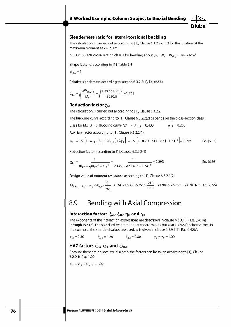
8 Worked Example: Column Subject to Biaxial Bending
76 Program ALUMINIUM © 2014 Dlubal Software GmbH
Slenderness ratio for lateral-torsional buckling The calculation is carried out according to [1], Clause 6.3.2.3 or I.2 for the location of the maximum moment at x = 2.0 m.
IS 300/150/4/8, cross-section class 3 for bending about y-y: ³cm51.397WW y,ely ==
Shape factor α according to [1], Table 6.4
1u,3 =α
Relative slenderness according to section 6.3.2.3(1), Eq. (6.58)
741.16.2820
5.2151.3971M
fW
cr
oy,elLT =
⋅⋅=
α=λ
Reduction factor χLT The calculation is carried out according to [1], Clause 6.3.2.2.
The buckling curve according to [1], Clause 6.3.2.2(2) depends on the cross-section class.
Class for My: 3 ⇒ Buckling curve "2" ⇒ 400.0LT.0 =λ 200.0LT =α
Auxiliary factor according to [1], Clause 6.3.2.2(1)
( )[ ] ( )[ ] 149.2741.14.0741,12.015.015.0 22LTLT,0LTLTLT =+−⋅+⋅=λ+λ−λ⋅α+⋅=φ Eq. (6.57)
Reduction factor according to [1], Clause 6.3.2.2(1)
293.0741.1149.2149.2
11222
LT2
LTLT
LT =−+
=λ−Φ+Φ
=χ Eq. (6.56)
Design value of moment resistance according to [1], Clause 6.3.2.1(2)
kNm79.22Nmm2278822910.1
215397511000.1293.0
fWM
1M
oy,elyLTRd.b ==⋅⋅⋅=
γ⋅⋅α⋅χ= Eq. (6.55)
8.9 Bending with Axial Compression
Interaction factors ξyc, ξzc, ηc and γc The exponents of the interaction expressions are described in clause 6.3.3.1(1), Eq. (6.61a) through (6.61e). The standard recommends standard values but also allows for alternatives. In the example, the standard values are used. γ0 is given in clause 6.2.9.1(1), Eq. (6.42b).
80.0c =η 80.0yc =ξ 80.0zc =ξ 00.10c =γ=γ
HAZ factors ω0, ωx and ωxLT Because there are no local weld seams, the factors can be taken according to [1], Clause 6.2.9.1(1) as 1.00.
00.1LT,xx0 =ω=ω=ω

8 Worked Example: Column Subject to Biaxial Bending
77 Program ALUMINIUM © 2014 Dlubal Software GmbH
Design values of resistance NRd, My,Rd, Mz,Rd The design values of resistance are determined according to [1], Clause 6.3.3.1(5) and 6.3.3.2(1).
kN583.612N61258310.1
2151.3134000.1
fAN
1M
oeffRd ==⋅⋅=
γ⋅⋅κ=
Shape factor α according to [1], Table 6.4
1u,3 =α
Design value of moment resistance about y-axis
kNm695.77Nmm7769533210.1
2153975111
fWM
1M
oel,yyRd,y ==⋅⋅=
γ⋅⋅α=
Design value of moment resistance about z-axis
kN391.9Nmm939131710.1
21548049000.1
fWM
1M
oel,zzRd,z ==⋅⋅=
γ⋅⋅α=
Flexural buckling according to [1], Clause 6.3.3.1
Interaction for flexural buckling about major axis and bending moment My
00.1M
M
N
N
Rd,y0
Ed,yyc
Rdy,xy
Ed ≤⋅ω
+
⋅ω⋅χ
ξ
Eq. (6.59)
00.1695.7700.1
8583.61200.1903.0
168.0
≤⋅
+
⋅⋅
00.1162.0103.0059.0 ≤=+
Interaction for flexural buckling about minor axis and bending moment Mz
00.1M
M
N
N
Rd,z0
Ed,z
Rdz,xz
Edc
≤⋅ω
+
⋅ω⋅χ
η
Eq. (6.60)
00.1391.900.1
2583.61200.1168.0
168.0
≤⋅
+
⋅⋅
00.1516.029.0225.0 ≤=+
Torsional-flexural buckling according to [1], Clause 6.3.3.2
00.1M
M
M
M
N
Nzccc
Rd,z0
Ed,z
Rd,yxLTLT
Ed,y
Rdz,xz
Ed ≤
⋅ω+
⋅ω⋅χ+
⋅ω⋅χ
ξγη
Eq. (6.63)
00.1391.900.1
2695.7700.1293.0
8583.61200.1168.0
168.00.18.0
≤
⋅+
⋅⋅+
⋅⋅
00.1867.029.0351.0225.0 ≤=++
Note: In Eq. (6.59) and (6.60) for flexural buckling, χy and χz are the reduction factors for buckling in the z-x or y-x plane.
In Eq. (6.63) for torsional-flexural buckling, χz is the reduction factor for buckling, if one of the two flanges shows lateral deflection (buckling in x-y plane or flexural-torsional buckling).

8 Worked Example: Column Subject to Biaxial Bending
78 Program ALUMINIUM © 2014 Dlubal Software GmbH
Results of the ALUMINIUM calculation
Elastic critical moment for torsional buckling
Ncr,T 303.19 kN Eq. (I.16)
Modulus of elasticity E 7000.0 kN/cm2 3.2.5(1)
Second moment of area Iy 59626700 mm4
Effective member length Lcr,y 4000.0 mm
Elastic flexural buckling force Ncr,y 2574.65 kN Eq. (I.14)
Second moment of area Iz 2882920 mm4
Effective member length Lcr,z 4000.0 mm
Elastic flexural buckling force Ncr,z 124.48 kN Eq. (I.15)
Relative slenderness λ_z 2.327 > λ_0 6.3.1.2(4)
Buckling curve BCz 1 Tab. 6.6
Imperfection factor αz 0.200 Tab. 6.6
Auxiliary factor φz 3.429 6.3.1.2(1)
Reduction factor χz 0.168 Eq. (6.50)
Cross-sectional area A 3800.0 mm2
Characteristic proof strength fo 21.50 kN/cm2 Tab. 3.2.1
Buckling curve BCLT 2 6.3.2.2(2)
Imperfection factor αLT 0.200 6.3.2.2(2)
Shear modulus G 2700.0 kN/cm2 3.2.5(1)
Effective length factor kz 1.000
Effective length factor kw 1.000
Length L 4000.0 mm
Warping constant of cross-section Iw 6.0552E+10 mm6
Torsional constant J 87883.6 mm4
Elastic critical moment for LTB Mcr,0 24.92 kNm
Elastic critical moment for LTB Mcr 28.19 kNm
Moment C1 1.131 Eigenvalue solution
Modulus of cross-section Sy 397511 mm3
Relative slenderness λ_LT 1.741 6.3.2.3
Auxiliary factor φLT 2.150 6.3.2.2(1)
Reduction factor χLT 0.293 Eq. (6.56)
Elastic critical load for torsional buckling
Ncr,T 303.19 kN Eq. (I.16)
Axial force (compression) NEd 16.00 kN
Factor for section with localized weld
ωx,y 1.000 6.3.3
Factor for section with localized weld
ωx,z 1.000
Exponent ξyc 0.800 6.3.3
Exponent ξzc 0.800 6.3.3

8 Worked Example: Column Subject to Biaxial Bending
79 Program ALUMINIUM © 2014 Dlubal Software GmbH
Factor for section with localized weld
ω0 1.000 6.2.9, 6.3.3
HAZ factor ωxLT 1.000 6.3.3
Exponent ωc 1.000 6.3.3
Exponent ηc 0.800 6.3.3
Governing cross-sectional area Aeff 3134.15 mm2
Axial force resistance NRd 612.58 kN Eq. (6.22)
Partial safety factor γM1 1.100 Tab. 6.1
Design component for N ηNy 0.054 < 1 Eq. (6.59)
Design component for N ηNz 0.225 < 1 Eq. (6.60)
Moment My,Ed 8.00 kNm
Moment ΔMy,Ed 0.00 kNm
Modulus of cross-section Sy 397511 mm3
Moment resistance My,Rd 77.70 kNm
Moment component ηMy 0.35 < 1
Moment Mz,Ed 2.00 kNm
Moment ΔMz,Ed 0.00 kNm
Modulus of cross-section Wz 48048.6 mm3
Moment resistance Mz,Rd 9.39 kNm
Moment component ηMz 0.290 < 1
Design 1 η1 0.157 < 1 Eq. (6.59)
Design 2 η2 0.516 < 1 Eq. (6.60)
Design 3 η3 0.867 < 1 Eq. (6.63)
Check η 0.867 < 1

A Literature
80 Program ALUMINIUM © 2014 Dlubal Software GmbH
A Literature
[1] EN 1999-1-1: Design of aluminium structures - Part 1-1: General Structural Rules, May 2007
[2] EAA - European Aluminium Association TALAT Lectures: http://eaa.net/eaa/education/TALAT/index.htm
[3] Designers' Guide to Eurocode 9: Design of Aluminium Structures EN 1999-1-1 and -1-4 ICE Publishing, London 2012

B Index
81 Program ALUMINIUM © 2014 Dlubal Software GmbH
B Index A Accidental ......................................................................... 11
Alloy .................................................................................... 23
Alternative values .......................................................... 33
Amplification factor ....................................................... 35
Angle section ................................................................... 34
Axis ............................................................................... 22, 26
B Background graphic ...................................................... 53
Beam type ......................................................................... 32
Browsing through windows ......................................... 8
Buckling ............................................................................. 25
Buckling length ............................................................... 24
Butt...................................................................................... 23
Buttons .............................................................................. 52
C Calculation ........................................................................ 33
Cantilever ................................................................... 21, 32
Characteristic ................................................................... 12
Classification .................................................................... 34
Clipboard .......................................................................... 65
Closed cross-section...................................................... 40
Color bar ............................................................................ 52
Color spectrum ............................................................... 56
Colored diagram ............................................................. 56
Comment ............................................................................ 9
Control panel ................................................................... 56
Cross-section ..................................................... 16, 34, 62
Cross-section check ....................................................... 44
Cross-section class ......................................................... 33
Cross-section database ................................................ 39
Cross-section library ...................................................... 16
Cross-section optimization ......................................... 62
Cross-section type ......................................................... 18
D Decimal places ......................................................... 14, 64
Deflection ......................................................................... 12
Deformation analysis .................................................... 32
Design ....................................................... 9, 18, 42, 43, 44
Design case ........................................................ 54, 60, 61
Design ratio ...................................................................... 43
Design situation ................................................ 11, 12, 44
Detail settings ................................................................. 33
Display navigator .................................................... 54, 56
Distance xs ........................................................................ 36
E Effective length .......................................... 24, 26, 28, 65
Effective length factor .................................................. 26
Elastic critical moment for LTB .................................. 35
Equivalent member length ........................................ 24
Evaluation of results...................................................... 52
Excel ................................................................................... 66
Exit ALUMINIUM ................................................................ 8
Export ................................................................................ 65
Export cross-section ...................................................... 63
Export effective length ................................................ 65
Export material ............................................................... 65
F Favorite ............................................................................. 62
Fillet .................................................................................... 23
Filter ............................................................................ 52, 56
Filter members................................................................ 57
Flexural buckling ............................................... 21, 25, 35
Frequent ........................................................................... 12
G General data ....................................................................... 8
Graphic .............................................................................. 53
Graphic printout............................................................. 58
H HAZ ..................................................................................... 17
Heat path .......................................................................... 23
Heat-affected zone ................................................. 22, 34
Hidden result diagram ................................................. 56
I Info about cross-section .............................................. 19
Installation .......................................................................... 6
Intermediate lateral restraint ..................................... 21
Internal forces .......................................................... 47, 63
L Lateral and torsional restraint ...................... 21, 26, 27
Lateral restraint .............................................................. 21
Lateral-torsional buckling .................................... 21, 26
Length ........................................................................ 24, 50
B Index
82 Program ALUMINIUM © 2014 Dlubal Software GmbH
Limit deformation .......................................................... 38
Limit values .................................................... 9, 12, 13, 36
List of members .............................................................. 32
Load application ............................................................. 36
Load case ............................................................ 10, 12, 47
Load combination .......................................................... 10
Location x ......................................................................... 43
LTB length ......................................................................... 27
M Material ................................................................ 14, 23, 65
Material description ...................................................... 15
Material library ................................................................ 15
Material properties ........................................................ 14
Member end release ..................................................... 31
Member slendernesses ......................................... 39, 49
Member-like input .................................................. 28, 36
Members ............................................................................. 9
Method .............................................................................. 23
MIG ...................................................................................... 23
N National Annex ...........................................................9, 13
Navigator ............................................................................ 8
Nodal support ................................................................. 29
O Open module .................................................................... 6
OpenOffice ....................................................................... 66
Optimization ............................................... 18, 39, 62, 63
P Panel ........................................................................ 7, 54, 56
Parametric section ......................................................... 62
Part ...................................................................................... 50
Partial safety factors ...................................................... 13
Parts list ...................................................................... 50, 51
Persistent .......................................................................... 11
Plate girder ....................................................................... 34
Precamber ........................................................................ 32
Print .................................................................................... 58
Printout report ......................................................... 58, 59
Product form .................................................................... 15
Q Quasi-permanent ........................................................... 12
R Reference length ............................................................ 12
Relatively .................................................................... 21, 22
Remark .............................................................................. 18
Rendering ......................................................................... 56
Result combination .......................................... 10, 11, 52
Result diagram ......................................................... 55, 58
Result values .................................................................... 53
Result windows .............................................................. 42
Results display ................................................................ 54
RSBUCK .............................................................................. 25
RSTAB graphic ................................................................. 58
RSTAB work window ..................................................... 53
S Second-order effects .................................................... 35
Serviceability ............................................................ 32, 38
Serviceability limit state ....................................... 12, 52
Set of members .......... 9, 28, 29, 31, 32, 36, 45, 48, 51
SHAPE-THIN ..................................................................... 34
SHAPE-THIN section ............................................... 17, 39
Shifted member ends ................................................... 38
Slenderness ............................................................... 37, 49
Special cases .................................................................... 36
Stability ............................................................................. 35
Stability analysis ...................................................... 21, 44
Start ALUMINIUM .............................................................. 6
Start calculation ............................................................. 41
Stress point ...................................................................... 19
Sum ..................................................................................... 51
Surface area ..................................................................... 50
T Tapered member ........................................................... 18
Temperature .................................................................... 23
TIG ....................................................................................... 23
Torsion ............................................................................... 37
Torsional buckling ......................................................... 37
Torsional length ............................................................. 27
Torsional-flexural buckling .................................. 21, 37
Transient ........................................................................... 11
Transverse load............................................................... 36
Transverse weld....................................................... 22, 34
Triaxial state of stress ................................................... 13
U Ultimate limit state ........................................... 10, 33, 52
Undeformed initial system ......................................... 38
Units ............................................................................ 14, 64
User profile ....................................................................... 64

B Index
83 Program ALUMINIUM © 2014 Dlubal Software GmbH
V View mode ........................................................................ 53
Visibilities .......................................................................... 56
Volume .............................................................................. 51
W Warping length factor .................................................. 27
Warping restraint ........................................................... 27
Weight ............................................................................... 51
Weld seam ................................................................. 17, 22
Weld type ......................................................................... 23
WEZ .................................................................................... 22
Window ................................................................................ 8
X x-location ................................................................... 43, 47