Embed Size (px)
Citation preview
Installation Guidelines
4.1 Code Reference The “authority having jurisdiction” should be referenced to determine what law, ordinance or code shall apply in the use of flexible duct. Ducts conforming to NFPA 90A or 90B shall meet the following requirements: a. Shall be tested in accordance with Sections 5-21 of Underwriters Laboratories Standard
for Factory-Made Air Ducts and Air Connectors, UL 181.
b. Shall be installed in accordance with the conditions of their listing.
c. Shall be installed within the limitations of the applicable NFPA 90A or 90B Standard.
4.2 General The routing of flexible duct, the number of bends, the number or degrees in each bend and the amount of sag allowed between support joints will have serious effects on system performance due to the increased resistance each introduces. Use the minimum length of flexible duct to make connections. It is not recommended that excess length of ducts be installed to allow for possible future relocations of air terminal devices. Avoid installations where exposure to direct sunlight can occur, e.g. turbine vents, sky lights, canopy windows, etc. Prolonged exposure to sunlight will cause degradation of the vapor barrier. Direct exposure to UV light from a source lamp installed within the HVAC system will cause degradation of some inner core/liner materials. Terminal devices shall be supported independently of the flexible duct. Repair torn or damaged vapor barrier/jacket with duct tape listed and labeled to Standard UL 181B. If internal core is penetrated, replace flexible duct or treat as a connection.
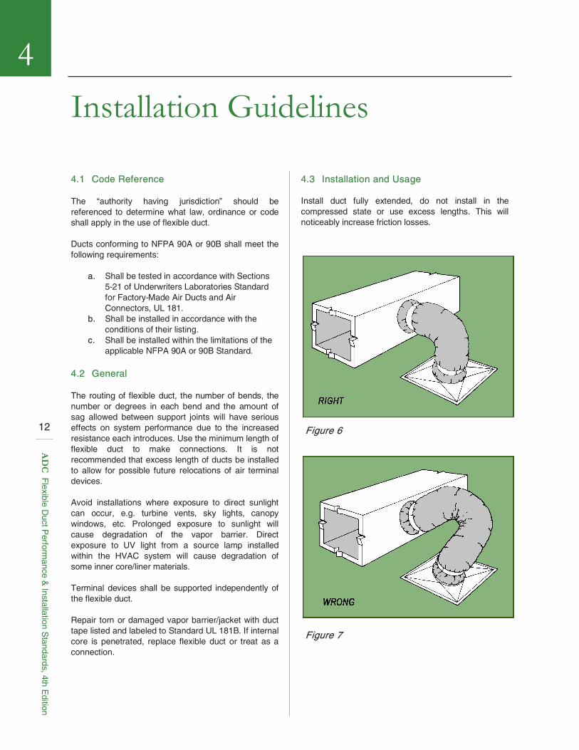
4.3 Installation and Usage Install duct fully extended, do not install in the compressed state or use excess lengths. This will noticeably increase friction losses.
4
Figure 6
Figure 7
12
AD
C F
lexible Duct P
erformance &
Installation Standards, 4th E
dition
Installation Guidelines . . . continued
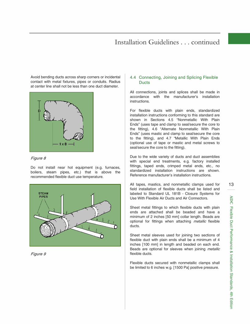
Avoid bending ducts across sharp corners or incidental contact with metal fixtures, pipes or conduits. Radius at center line shall not be less than one duct diameter.
4.4 Connecting, Joining and Splicing Flexible Ducts
All connections, joints and splices shall be made in accordance with the manufacturer’s installation instructions. For flexible ducts with plain ends, standardized installation instructions conforming to this standard are shown in Sections 4.5 “Nonmetallic With Plain Ends” (uses tape and clamp to seal/secure the core to the fitting), 4.6 “Alternate Nonmetallic With Plain Ends” (uses mastic and clamp to seal/secure the core to the fitting), and 4.7 “Metallic With Plain Ends (optional use of tape or mastic and metal screws to seal/secure the core to the fitting). Due to the wide variety of ducts and duct assemblies with special end treatments, e.g. factory installed fittings, taped ends, crimped metal ends, etc., no standardized installation instructions are shown. Reference manufacturer’s installation instructions. All tapes, mastics, and nonmetallic clamps used for field installation of flexible ducts shall be listed and labeled to Standard UL 181B - Closure Systems for Use With Flexible Air Ducts and Air Connectors. Sheet metal fittings to which flexible ducts with plain ends are attached shall be beaded and have a minimum of 2 inches [50 mm] collar length. Beads are optional for fittings when attaching metallic flexible ducts. Sheet metal sleeves used for joining two sections of flexible duct with plain ends shall be a minimum of 4 inches [100 mm] in length and beaded on each end. Beads are optional for sleeves when joining metallic flexible ducts. Flexible ducts secured with nonmetallic clamps shall be limited to 6 inches w.g. [1500 Pa] positive pressure.
Figure 8 Do not install near hot equipment (e.g. furnaces, boilers, steam pipes, etc.) that is above the recommended flexible duct use temperature.
Figure 9
13
AD
C F
lexible Duct P
erformance &
Installation Standards, 4th E
dition
Installation Guidelines . . . continued
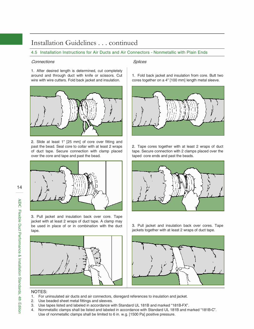
Connections Splices
4.5 Installation Instructions for Air Ducts and Air Connectors - Nonmetallic with Plain Ends
1. After desired length is determined, cut completely around and through duct with knife or scissors. Cut wire with wire cutters. Fold back jacket and insulation.
2. Tape cores together with at least 2 wraps of duct tape. Secure connection with 2 clamps placed over the taped core ends and past the beads.
2. Slide at least 1" [25 mm] of core over fitting and past the bead. Seal core to collar with at least 2 wraps of duct tape. Secure connection with clamp placed over the core and tape and past the bead.
3. Pull jacket and insulation back over core. Tape jacket with at least 2 wraps of duct tape. A clamp may be used in place of or in combination with the duct tape.
3. Pull jacket and insulation back over cores. Tape jackets together with at least 2 wraps of duct tape.
NOTES: 1. For uninsulated air ducts and air connectors, disregard references to insulation and jacket. 2. Use beaded sheet metal fittings and sleeves. 3. Use tapes listed and labeled in accordance with Standard UL 181B and marked “181B-FX”. 4. Nonmetallic clamps shall be listed and labeled in accordance with Standard UL 181B and marked “181B-C”. Use of nonmetallic clamps shall be limited to 6 in. w.g. [1500 Pa] positive pressure.
1. Fold back jacket and insulation from core. Butt two cores together on a 4" [100 mm] length metal sleeve.
14
AD
C F
lexible Duct P
erformance &
Installation Standards, 4th E
dition
Installation Guidelines . . . continued
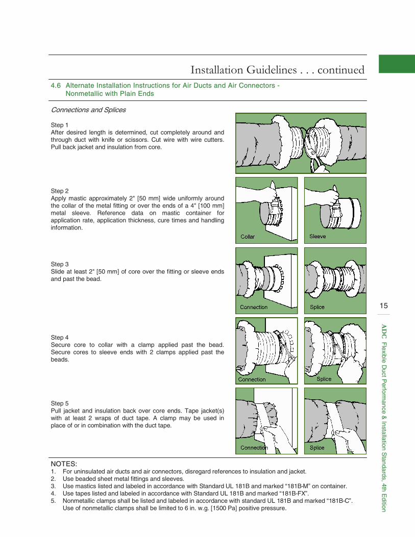
4.6 Alternate Installation Instructions for Air Ducts and Air Connectors - Nonmetallic with Plain Ends
Connections and Splices Step 1 After desired length is determined, cut completely around and through duct with knife or scissors. Cut wire with wire cutters. Pull back jacket and insulation from core. Step 2 Apply mastic approximately 2" [50 mm] wide uniformly around the collar of the metal fitting or over the ends of a 4" [100 mm] metal sleeve. Reference data on mastic container for application rate, application thickness, cure times and handling information. Step 3 Slide at least 2" [50 mm] of core over the fitting or sleeve ends and past the bead. Step 4 Secure core to collar with a clamp applied past the bead. Secure cores to sleeve ends with 2 clamps applied past the beads. Step 5 Pull jacket and insulation back over core ends. Tape jacket(s) with at least 2 wraps of duct tape. A clamp may be used in place of or in combination with the duct tape.
NOTES: 1. For uninsulated air ducts and air connectors, disregard references to insulation and jacket. 2. Use beaded sheet metal fittings and sleeves. 3. Use mastics listed and labeled in accordance with Standard UL 181B and marked “181B-M” on container. 4. Use tapes listed and labeled in accordance with Standard UL 181B and marked “181B-FX”. 5. Nonmetallic clamps shall be listed and labeled in accordance with standard UL 181B and marked “181B-C”. Use of nonmetallic clamps shall be limited to 6 in. w.g. [1500 Pa] positive pressure.
15
AD
C F
lexible Duct P
erformance &
Installation Standards, 4th E
dition
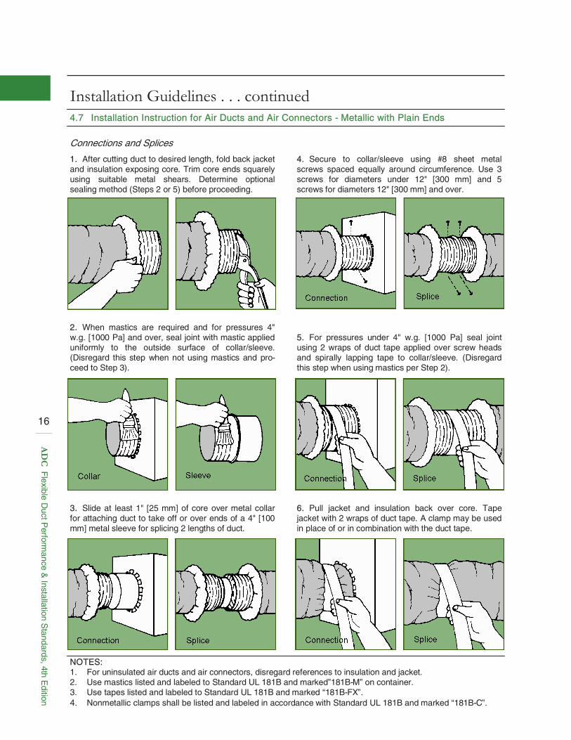
Installation Guidelines . . . continued 4.7 Installation Instruction for Air Ducts and Air Connectors - Metallic with Plain Ends
Connections and Splices
NOTES: 1. For uninsulated air ducts and air connectors, disregard references to insulation and jacket. 2. Use mastics listed and labeled to Standard UL 181B and marked”181B-M” on container. 3. Use tapes listed and labeled to Standard UL 181B and marked “181B-FX”. 4. Nonmetallic clamps shall be listed and labeled in accordance with Standard UL 181B and marked “181B-C”.
1. After cutting duct to desired length, fold back jacket and insulation exposing core. Trim core ends squarely using suitable metal shears. Determine optional sealing method (Steps 2 or 5) before proceeding.
4. Secure to collar/sleeve using #8 sheet metal screws spaced equally around circumference. Use 3 screws for diameters under 12" [300 mm] and 5 screws for diameters 12" [300 mm] and over.
2. When mastics are required and for pressures 4" w.g. [1000 Pa] and over, seal joint with mastic applied uniformly to the outside surface of collar/sleeve. (Disregard this step when not using mastics and pro-ceed to Step 3).
3. Slide at least 1" [25 mm] of core over metal collar for attaching duct to take off or over ends of a 4" [100 mm] metal sleeve for splicing 2 lengths of duct.
5. For pressures under 4" w.g. [1000 Pa] seal joint using 2 wraps of duct tape applied over screw heads and spirally lapping tape to collar/sleeve. (Disregard this step when using mastics per Step 2).
6. Pull jacket and insulation back over core. Tape jacket with 2 wraps of duct tape. A clamp may be used in place of or in combination with the duct tape.
16
AD
C F
lexible Duct P
erformance &
Installation Standards, 4th E
dition
This page has been intentionally left blank for future use.
17
AD
C F
lexible Duct P
erformance &
Installation Standards, 4th E
dition
Installation Guidelines . . . continued
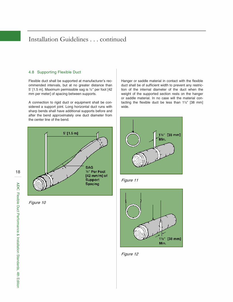
4.8 Supporting Flexible Duct Flexible duct shall be supported at manufacturer’s rec-ommended intervals, but at no greater distance than 5’ [1.5 m]. Maximum permissible sag is ½ " per foot [42 mm per meter] of spacing between supports. A connection to rigid duct or equipment shall be con-sidered a support joint. Long horizontal duct runs with sharp bends shall have additional supports before and after the bend approximately one duct diameter from the center line of the bend.
Hanger or saddle material in contact with the flexible duct shall be of sufficient width to prevent any restric-tion of the internal diameter of the duct when the weight of the supported section rests on the hanger or saddle material. In no case will the material con-tacting the flexible duct be less than 1½ ” [38 mm] wide.
Figure 10
Figure 11
Figure 12
18
AD
C F
lexible Duct P
erformance &
Installation Standards, 4th E
dition
Installation Guidelines . . . continued
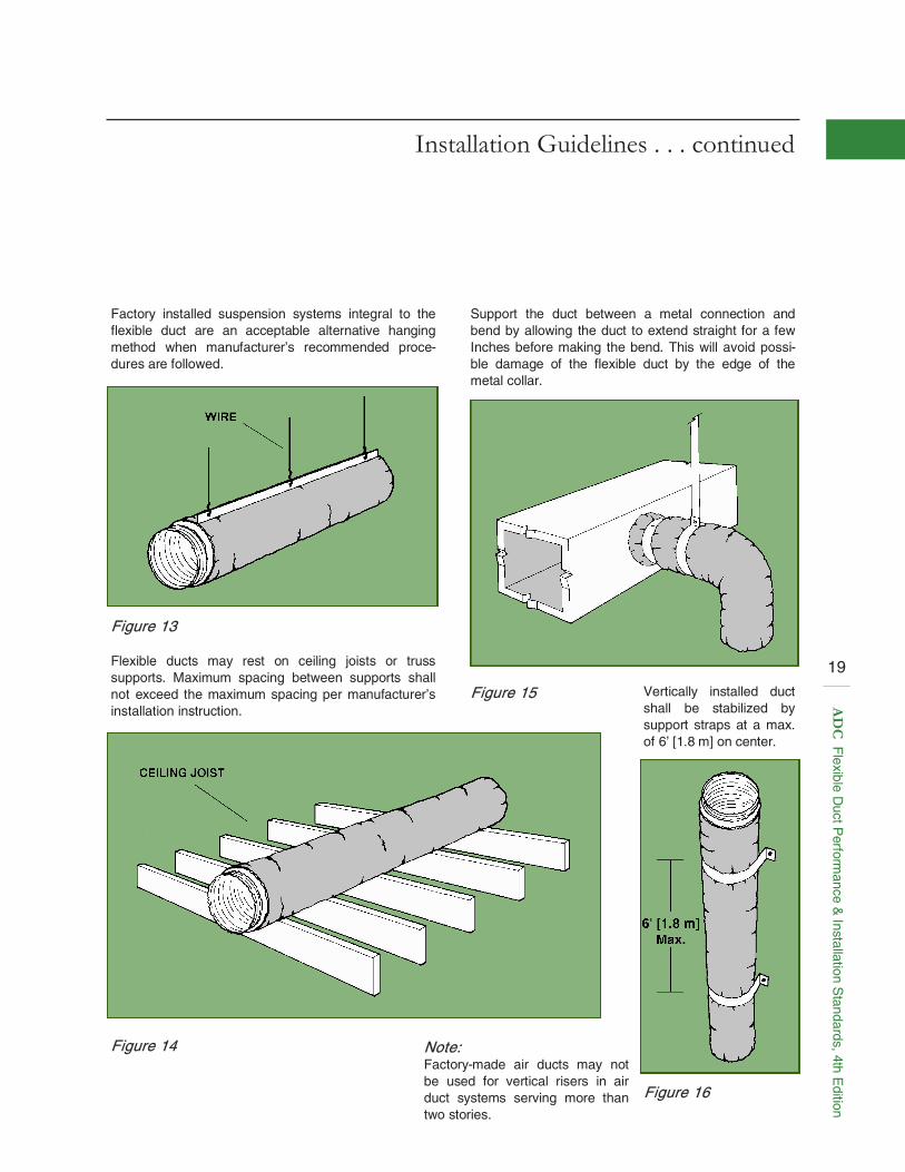
Factory installed suspension systems integral to the flexible duct are an acceptable alternative hanging method when manufacturer’s recommended proce-dures are followed.
Support the duct between a metal connection and bend by allowing the duct to extend straight for a few Inches before making the bend. This will avoid possi-ble damage of the flexible duct by the edge of the metal collar.
Figure 13 Flexible ducts may rest on ceiling joists or truss supports. Maximum spacing between supports shall not exceed the maximum spacing per manufacturer’s installation instruction.
Figure 15 Vertically installed duct shall be stabilized by support straps at a max. of 6’ [1.8 m] on center.
Figure 16
Figure 14 Note: Factory-made air ducts may not be used for vertical risers in air duct systems serving more than two stories.
19
AD
C F
lexible Duct P
erformance &
Installation Standards, 4th E
dition