Embed Size (px)
Citation preview

M.S-PHYS-516, Electronics-Shoman Das , ID: 10201189 Page 1 of 23
Department of Physics, University Of Chittagong.
Master of Science-PHYS-516
Name: Shoman Das
Session: 2013-2014
ID: 10201189
Group: 04
Link: https://drive.google.com/file/d/0Bzr-iYfK0UWmTEFmWEhxcU1lN1k/view?usp=sharing

M.S-PHYS-516, Electronics-Shoman Das , ID: 10201189 Page 2 of 23
Appendix
Serial
No.
Date
Name of the experiment
Page
No.
Initials Remarks
01
02-Aug 2015
To construct of a 4-bit DAC
using resistance network,
signal generator and different
IC’s.
03-13
02.
18-Aug-2015
To construct of a single
decimal digit display system
using different IC’s and a
seven (7) segment display
unit.
14-23

M.S-PHYS-516, Electronics-Shoman Das , ID: 10201189 Page 3 of 23
Date of the Experiment: 02-Aug 2015
Experiment No.: 01
Name of the Experiment:
To construct of a 4-bit DAC using resistance network, signal generator and different
IC’s.
THEORY:
In electronics, a digital to analog conversion (DAC or Digital to Analog) is a process that
converts a digital (usually binary) to an analog signal (current voltage or electric charge)
that is proportional to the digital value. For each digital input number the D/A converts
output voltage is unique. Signals are easily stored and transmitted into the digital form
but a DAC is needed for the signal to be recognized by human sense or other non-digital
system a common use of DAC is generation of audio signals from digital information in
music player.
In figure -1(a), we see that digital clock pulses are used the input from signal generator.
A typical block diagram of 4-bit or 4-BIT DAC converting process is shown in figure -2(a).
The weighted resistor DAC:
In this position, it indicates that the resistance network that will change each
digital level into equivalent binary weighted voltage.
For 4–bit binary signal the resistance network is shown in figure -2(b), Hence
RA ,RB, RC and RD are connected parallel 0=0V and 1=+5V. Here

M.S-PHYS-516, Electronics-Shoman Das , ID: 10201189 Page 4 of 23
Fig -1(a): Circuit diagram to construct a 4-bit DAC
M.S-PHYS-516, Electronics-Shoman Das , ID: 10201189 Page 5 of 23
𝑅𝐴, 𝑅𝐵, 𝑅𝐶 𝑎𝑛𝑑 𝑅𝐷 are connected to the binary output. From counter IC -7490,
𝑄𝐴, 𝑄𝐵 , 𝑄𝐶 𝑎𝑛𝑑 𝑄𝐷
IC-7490(decode and binary counter):
A digital circuit that can count the no of
pulses is called counter. A counter express the result of counting as the binary number.
The counter is composed of flip-flops. A 3-bit counter consisting of 3-flip-flops.A
electronic counter is not only used for controlling some other activities. The different
types of are given below.
R/ 2R Ladder method:
One of the most widely used DAC circuit that satisfies this
requirement is the R/ 2R Ladder network, where the resistance value span a range of only
2 to 1 one such DAC is shown in fig -2(c).The current Iout depends on the position of the
four switches and the binary inputs control the states of the switches. This current is
allowed to flow through an op-amp current-to-voltage converters to develop 𝑉𝑜𝑢𝑡. The
value of 𝑉𝑜𝑢𝑡 is given by the expression,
𝑉𝑜𝑢𝑡 = −𝑉𝑅𝐸𝐹
16× 𝐵
Where, B is the value of the binary input, which can range from (0000) (0) to 1111(15)
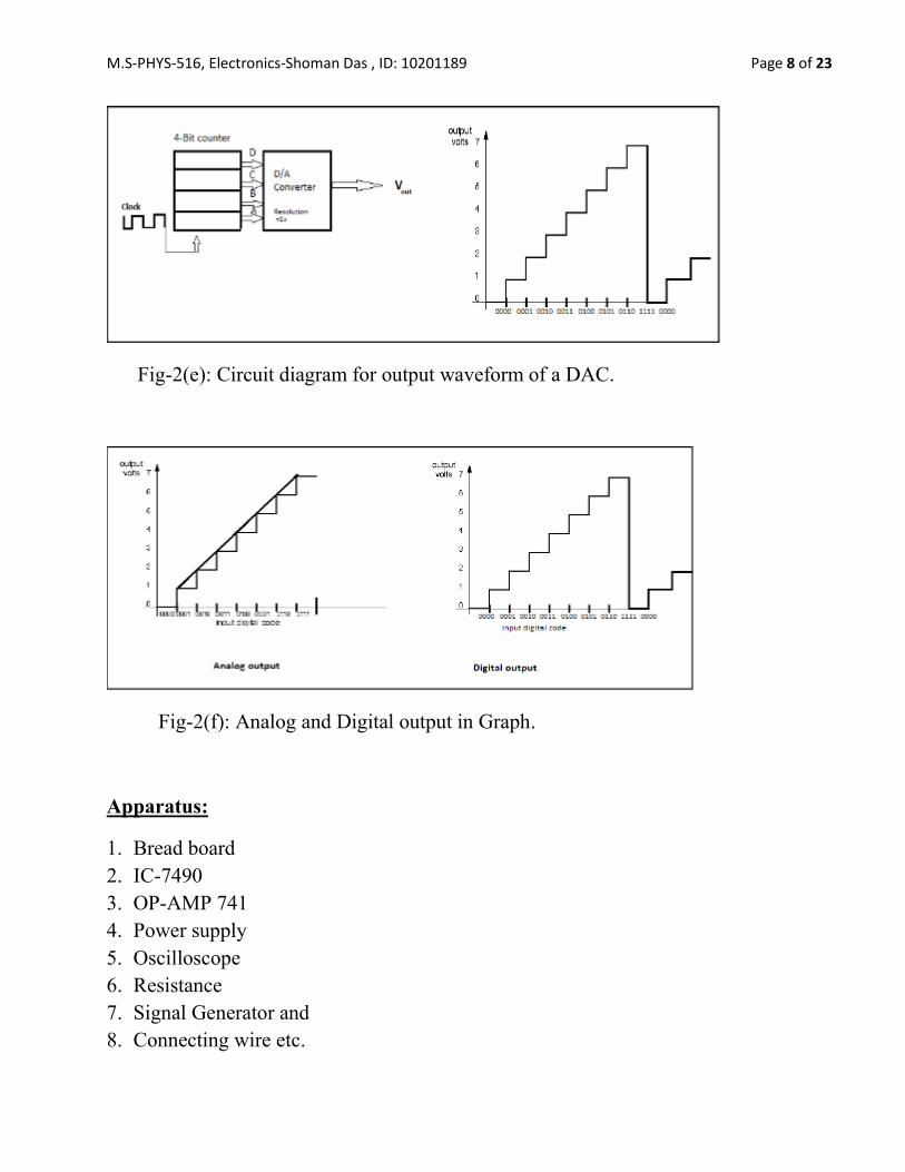
Resolution (Step size)
Resolution of a D/A converter is defined as the smallest change
that can occur in the analog output as a result of a change in the digital output. The
resolution is always equal to the weight of the L5B and is also referred to as the step size
because it is the amount that 𝑉𝑜𝑢𝑡change as the digital input voltage is changed from
one’s to the next. As the counter is being continued cycled its 16 states by the clock
signal, the DAC output is a staircase wave that goes up

M.S-PHYS-516, Electronics-Shoman Das , ID: 10201189 Page 6 of 23
Fig-2(d): Circuit diagram for basic R/2R ladder DAC.

M.S-PHYS-516, Electronics-Shoman Das , ID: 10201189 Page 7 of 23
1V per step. When the counter recycles to 0000, the DAC output returns to 0V.The
resolution or step size is the size of the jumps in the staircase waveform; in this case, each
step size is 1V.The staircase has 16 levels corresponding to the 16 input states but there
are only 15 steps or jumps between the 0V level and Full scale. In general, For an N-bit
DAC the number of different levels will be 2N-1.The resolution of a DAC is shown in
figure 1(d).
Offset error:
Ideally, the output of a DAC will be zero volts when the binary input is all 0’s. In
practice, however, there will be a small output voltage. For this situation, this is called
offset error. This offset error, if not corrected will be added to the expected DAC output
for all input cases.
Setting Time:
The operating speed of a DAC is usually specified by giving its setting
time, which is the time required for the DAC output to go from zero to full scale as the
binary input is changed. From all 0’s to all 1’s.Actually the setting time is measured as
the time for the DAC output to the scale within +-1/2 step size or resolution of its final
value.
Monotonicity:
A DAC is monotonic of its output increases as the binary unit is
incremented from one value to the next. Another way to describe this is the staircase
output will have no downward step as the binary input is incremented from zero to full
scale.
Linearity:
If the analog o/p voltage may always increase at an equal rate (step size) with
the increase of the digital input. This is called linearity. Moreover, the analog o/p voltage
may not always increased at the equal rate with the increased of digital input. This
problem is called as the non-linearity problem.
M.S-PHYS-516, Electronics-Shoman Das , ID: 10201189 Page 8 of 23
Fig-2(e): Circuit diagram for output waveform of a DAC.
Fig-2(f): Analog and Digital output in Graph.
Apparatus:
1. Bread board
2. IC-7490
3. OP-AMP 741
4. Power supply
5. Oscilloscope
6. Resistance
7. Signal Generator and
8. Connecting wire etc.

M.S-PHYS-516, Electronics-Shoman Das , ID: 10201189 Page 9 of 23
Procedure:
At first all the connections were made as shown in Fig -2(a).
The biasing voltage was applied through using signal generator and power supply.
Then clock pulse were generated by signal generator and it was input for the IC-7490.
IC-7490 start counting and produce binary digit which was connected to the R-2R
ladder.
The output of the R-2R ladder network was used as an input of IC-741.
The output of the DAC was staircase waveform.
Then we look the output voltage by oscilloscope for different digital input.
Two graphs were drawn between digital inputs vs. output of the analog voltage, one
shows the staircase waveform (i.e. analog signal) anther shows linearity.

M.S-PHYS-516, Electronics-Shoman Das , ID: 10201189 Page 10 of 23
Experimental Data:
Table-1: Data for the output voltage of a DAC
No. of
Obsn.
Decimal
equivalent
of binary
inputs
Digital Input Code:
(𝑉𝑜𝑙𝑡′𝑠)
Digital
Input
Code
(𝐷𝑖𝑛)
Theoretical
output:
𝑉𝑜𝑢𝑡
= − ( 𝑏3
+1
2𝑏2 +
1
4 𝑏1
+1
8 𝑏0) 𝑉𝑅
(𝑉𝑜𝑙𝑡′𝑠)
Experimental
output
voltage (from
the oscillator)
(𝑉𝑜𝑢𝑡)
(𝑉𝑜𝑙𝑡′𝑠)
|𝑉𝑜𝑢𝑡|
(𝑉𝑜𝑙𝑡′𝑠)
bit3 bit2 bit1 bit0 Four
Bit
01 0 0 0 0 0 0000 0 0 0
02 1 0 0 0 5 0001 -0.625 -0.3 0.3
03 2 0 0 5 0 0010 -1.250 -0.6 0.6
04 3 0 0 5 5 0011 -1.875 -0.9 0.9
05 4 0 5 0 0 0100 -2.500 -1.2 1.2
06 5 0 5 0 5 0101 -3.125 -1.5 1.5
07 6 0 5 5 0 0110 -3.750 -1.8 1.8
08 7 0 5 5 5 0111 -4.375 -2.1 2.1
09 8 5 0 0 0 1000 -5.00 -2.4 2.4
10 9 5 0 0 5 1001 -5.625 -2.7 2.7

M.S-PHYS-516, Electronics-Shoman Das , ID: 10201189 Page 11 of 23
Fig-03: Graph for Digital input code vs. Analog output (voltages)

M.S-PHYS-516, Electronics-Shoman Das , ID: 10201189 Page 12 of 23
Calculation:
We know the output voltage:
𝑽𝒐𝒖𝒕 = − ( 𝒃𝟑 +𝟏
𝟐𝒃𝟐 +
𝟏
𝟒 𝒃𝟏 +
𝟏
𝟖 𝒃𝟎) 𝑽𝑹
Reference voltage, 𝑉𝑅 = 5 𝑣𝑜𝑙𝑡
Theoretical output voltage:
𝑽𝒐𝒖𝒕 = − ( 𝒃𝟑 +𝟏
𝟐𝒃𝟐 +
𝟏
𝟒 𝒃𝟏 +
𝟏
𝟖 𝒃𝟎) 𝑽𝑹
For equivalent decimal input 0000, 𝑉𝑜𝑢𝑡 = 0 𝑉.
For equivalent decimal input 0005, 𝑉𝑜𝑢𝑡 = − (0 +0
2+
0
4+
5
8) 𝑉 = −0.625 𝑉.
For equivalent decimal input 0050, 𝑉𝑜𝑢𝑡 = −1.25 𝑉.
For equivalent decimal input 0055, 𝑉𝑜𝑢𝑡 = −1.87 𝑉.
For equivalent decimal input 0505, 𝑉𝑜𝑢𝑡 = −3.125 𝑉.
For equivalent decimal input 0550, 𝑉𝑜𝑢𝑡 = −3.75 𝑉.
For equivalent decimal input 0555, 𝑉𝑜𝑢𝑡 = −4.375 𝑉.
For equivalent decimal input 5000, 𝑉𝑜𝑢𝑡 = −5 𝑉.
For equivalent decimal input 5005, 𝑉𝑜𝑢𝑡 = −5.625 𝑉.
Result:
A 4- bit DAC wiring resistance network(weighted resistance),Signal generator,IC-7490
and IC-741 has been constructed employing the technique of binary LADDER also
performed the steady state accuracy test mono-tocity test. Hence output of the theoretical
value is plotted in graph paper for this two characteristics. The output figure is shown in
tracing paper.

M.S-PHYS-516, Electronics-Shoman Das , ID: 10201189 Page 13 of 23
Discussion:
In this experiment, a four bit DAC has been successfully constructed by weighted resistor
network.
In this experiment, we have faced some problems in bread board connection. For this
reason we could not get accurate output shape in the oscilloscope and accurate result.
That’s why the graph didn’t follow the monotonicity exactly.
This problem may also arise due to the use of same IC for a long time in the experiment.
For fluctuation, power supply didn’t provide 5V accurately. Suitable R and C value have
been used in the circuit.

M.S-PHYS-516, Electronics-Shoman Das , ID: 10201189 Page 14 of 23
Experiment Date: 18-Aug-2015
Experiment No.: 02
Experiment Name:
To construct of a single decimal digit display system using different IC’s and a seven
(7) segment display unit.
THEORY:
One of the basic display components of a digital circuit is the seven segment display. It is
very popular device. It is most common way to display time on a clock and also one of
the easiest way to implement a numerical output. The use of 7-segment display is so
extensive that special integrated circuit (ICS) have been developed to take a four-bit
binary numeric input and create the output signals necessary to drive the display.
IC-555 as a timer (astable mode):
The IC-555 timer is a versatile integrated circuit timer that can be used in variety
applications. It is a highly stable controller capable of producing accurate timing pulse
and we can use this as a mono-stable or a stable multivibrator. With mono-stable
operation, the time delay is controlled by an external resistor and one capacitor with an
astable operation the frequency and duty cycle are accurately controlled with two external
resistors and one capacitors. The timer provided clock to the counter fig-b. The external
capacitor is initially held discharged by a transistor inside the timer. Upon application of
a negative trigger pulse of less than 1/3 VCC to pin 2, the flip-flop is set which both
releases the short circuit across the capacitor and drives the output high. The voltage
across the capacitor then increases exponentially for a period of t = 1.1 RA C, at the end
of which time the voltage equals 2/3 VCC. The comparator then resets the flip-flop which
in turn discharges the capacitor and drives the output to its low state. Fig-a shows the
waveforms generated in this mode of operation. Since the charge and the threshold level
of the comparator are both directly proportional to supply voltage, the timing interval is
independent of supply.
In fig-A shown the circuit diagram to construct a seven-segment display.

M.S-PHYS-516, Electronics-Shoman Das , ID: 10201189 Page 15 of 23
Fig -A: Circuit diagram to construct a seven-segment display.

M.S-PHYS-516, Electronics-Shoman Das , ID: 10201189 Page 16 of 23
During the timing cycle when the output is high, the further application of a trigger pulse
will not affect the circuit so long as the trigger input is returned high at least 10 μs before
the end of the timing interval. However the circuit can be reset during this time by the
application of a negative pulse to the reset terminal (pin 4). The output will then remain
in the low state until a trigger pulse is again applied. When the reset function is not in
use, TI recommends connecting the Reset pin to VCC to avoid any possibility of false
triggering. If the circuit is connected as shown in Figure (c) (pins 2 and 6 connected) it
will trigger itself and free run as a multivibrator. The external capacitor charges through
RA + RB and discharges through RB. Thus the duty cycle may be precisely set by the ratio
of these two resistors.
In this mode of operation, the capacitor charges and discharges between 1/3 VCC and 2/3
VCC. As in the triggered mode, the charge and discharge times, and therefore the
frequency are independent of the supply voltage.
Figure 1(d) shows the waveforms generated in this mode of operation.
VCC = 5 V Top Trace: Output 5V/Div.
TIME = 20μs/DIV. Bottom Trace: Capacitor Voltage 1V/Div.
𝑅𝐴 = 3.9 𝑘𝛺
𝑅𝐵 = 3 𝑘𝛺
Figure- 1(a): Mono-stable

M.S-PHYS-516, Electronics-Shoman Das , ID: 10201189 Page 17 of 23
Figure -1(b): Monostable Waveforms
𝐶 = 0.01 𝜇𝐹
The charge time (output high) is given by:
𝑡1 = 0.693 (𝑅𝐴 + 𝑅𝐵)𝐶 … … … … … … . . (1)
And the discharge time (output low) by:
𝑡2 = 0.693 (𝑅𝐵)𝐶 … … … … … … … … … . (2)
Thus the total period is:
𝑇 = 𝑡1 + 𝑡2 = 0.693 (𝑅𝐴 + 2𝑅𝐴)𝐶 … … … . … … (3)
The frequency of oscillation is:
𝑓 =1
𝑇=
1.44
(𝑅𝐴 + 2𝑅𝐵)𝐶… … … … … . (4)

M.S-PHYS-516, Electronics-Shoman Das , ID: 10201189 Page 18 of 23
Fig-1(c) may be used for quick determination of these RC values.
The duty cycle is:
𝐷 =𝑅𝐵
𝑅𝐴+2𝑅𝐵… … … … … … (5)
IC-7490(decode and binary counter):
A digital circuit that can count the no of pulses is called counter. A counter express the
result of counting as the binary number. The counter is composed of flip-flops. A 3-bit
counter consisting of 3-flip-flops. A electronic counter is not only used for controlling
some other activities. The different types of are given below.
Figure 1(e). Free Running Frequency
Figure 1(c). Astable
Figure 1(d). Astable Waveforms Fig. 1(f) simulated design of the system in sheet.

M.S-PHYS-516, Electronics-Shoman Das , ID: 10201189 Page 19 of 23
Binary Counter:
Binary counter can be controlled from j-k flip-flops by taking the o/p of a flip-flop is
used as the clock input for the next flip-flop. The j and k input so if each flip-flops are set
to produce a toggle (change state) at each cycle of the clock input. This produces a binary
number equal to the no of cycle of the input clock signals. This device sometimes called a
ripple through counter.
BCD Counter:
The name of BCD or Decode counter MOD-10. MOD comes from the word modulus.
Modulus indicates the total number of different o/p logic condition of a counter. MOD-10
counter gives 10 counts then it became reset (0000). MOD-10 counter does not count 10,
11, and 12,13,14,15. The counting sequence of a MOD-10 counter is given below-
_______________________________________
↳0→ 1→ 2→ 3→ 4→ 5→ 6→ 7→ 8→ 9 ↥
IC-7447:
IC-7447 is used as a seven-segment display driver. Here seven-segment
display driver connects BCD to decimal digit. A 4-bit BCD is provided as input to the IC-
7447 through LED for display decimal digit. It is very complex as comparable to the
ordinary decoder. Because to show, one digit o/pit is necessary to combine more than one
input. For example to show decimal number 6, it has to combine 0110, it has 4-terminals
for BCD input such as A, B, C, and D.

M.S-PHYS-516, Electronics-Shoman Das , ID: 10201189 Page 20 of 23
Seven-segment display:
A seven-segment display consists of seven LED’s arrangement in the pattern of eight.
Each segment is controlled individually so that any decimal digit can be displayed. A
seven-segment displays may 7, 8 or 9 leads on the clip.Figure-17 shows the diagram of
the typical seven-segment display. In this display light emitting diode is used. There are
two types of displays, one is common anode and another common cathode. Common
cathode types are used in this experiment. To make light appear, we must know which
segment to turn on and which to leave off. For example, to display ‘2’we need to turn on
segment a, b, g, e and d and leave other segment off. (ice the binary inputs to the display
are set to a=1,b=1,c=0,d=1,e=1,f=0 and g=1) then ‘2’ would be display.
Apparatus:
1) Bread board
2) Power supply
3) IC-7490
4) IC-555
5) IC-7447
6) Seven-segment display
7) Capacitor 𝐶1 = 0.1𝜇𝐹, 𝐶2 = 0.01 𝜇𝐹
8) Resistance 𝑅𝐴 = 1 𝑀𝛺, 𝑅𝐵 = 2 𝑀𝛺
9) Connecting wires
PROCEDURE:
1. All the connections were made as shown in the figure.
2. Then 5V biasing voltage is applied through the circuit using adapter.
3. Then clock pulses were generated by IC-555 timer and it is used as an input for the
IC-7490.
4. IC-7490 starts counting and produces BCD which is used as BCD input to seven
segment driver.
5. Every LED of seven segment is counted to the o/p of the IC-7447 display driver.
6. Then, we observed the decimal digit 0,1,2,3,4,5,6,7,8,9 on the display and was
shown to the respected teacher.

M.S-PHYS-516, Electronics-Shoman Das , ID: 10201189 Page 21 of 23
EXPERIMENTAL DATA:
Table-01: For time period and frequency
No of
obs.
Time
Clock
(Sec)
Time Clock
(Sec)
Time
period
(Sec)
Frequency
𝐹 =1
𝑇
(𝐻𝑧)
Average of
Time period
(𝑠𝑒𝑐)
Average
frequency
(𝐻𝑧)
1. 20 7 0.35 2.857
2. 25 9 0.36 2.78
3. 30 12 0.40 2.5
4. 35 14 0.40 2.5 0.381 2.6
5. 40 16 0.40 2.5
6. 45 17 0.37 2.652
7. 50 19 0.38 2.63

M.S-PHYS-516, Electronics-Shoman Das , ID: 10201189 Page 22 of 23
CALCULATION:
Time for 20 clock=7 sec, Time period, 𝑇1 =7
20 = 0.35 𝑠𝑒𝑐
Time for 25 clock=9 sec, Time period, 𝑇2 =9
25= 0.36 𝑠𝑒𝑐
Time for 30 clock=12 sec, Time period, 𝑇3 =12
30= 0.40 𝑠𝑒𝑐
Time for 35 clock=14 sec, Time period, 𝑇4 =14
35= 0.40 𝑠𝑒𝑐
Time for 40 clock=16 sec, Time period, 𝑇5 =16
40= 0.40 𝑠𝑒𝑐
Time for 45 clock=17 sec, Time period, 𝑇6 =17
45= 0.377 𝑠𝑒𝑐
Time for 50 clock=19 sec, Time period, 𝑇7 =19
50= 0.38 𝑠𝑒𝑐
Average Time period,
𝑇 =0.35 + 0.36 + 0.40 + 0.40 + 0.40 + 0.377 + 0.38
7= 0.381 (𝑠𝑒𝑐)
Frequency, 𝑓 =1
𝑇 =
1
0.381 = 2.6
Capacitor, C=0.1 𝛍F, Resistor R1=1M𝛺
Theoretically, Charging time,
𝑡𝑐ℎ𝑎𝑟𝑔𝑐 = 0.693(𝑅1 + 𝑅293(1) = {0.6 + 1) × 106 × 0.1 × 10−6}𝑠𝑒𝑐
= 0.1386 𝑠𝑒𝑐
Charging time,
𝑡𝑑𝑖𝑠 = 0.693𝑅2𝐶 = (0.693 × 1 × 0.1)𝑠𝑒𝑐 = 0.0693 𝑠𝑒𝑐
Time period = 𝑇𝑐ℎ𝑎𝑟𝑔 + 𝑇𝑑𝑖𝑠 = (0.1386 + 0.0693)𝑠𝑒𝑐 = 0.2079 𝑠𝑒𝑐
Practically, Time period = 0.381 𝑠𝑒𝑐

M.S-PHYS-516, Electronics-Shoman Das , ID: 10201189 Page 23 of 23
RESULT:
The combination of IC- 555 timer, IC-7490, counter, IC-7447, seven segment decoder IC
and seven segment display. It has been observed that the seven segment display showing
single decimal digit 0 to 9 properly.
Theoretically, Time period, = 0.2079 𝑠𝑒𝑐
Experimentally, Time period = 0.381 𝑠𝑒𝑐
And, Theoretically Frequency, 𝑓 = 4.81 𝑠𝑒𝑐
Experimentally, Frequency, 𝑓 = 2.62 𝑠𝑒𝑐
DISCUSSION:
In this experiment, A single decimal digit display unit has been successfully
constructed.IC-555 (timer) is used for generating rectangular pulse which represents the
astable mode of the IC-555. Pulsating LED of the output of the IC-555 as well as that it is
producing pulse. The pulse period has also been counted by the stopwatch that nearly
matches the theoretical value. The pulse was feed to the decode counter(IC-7490) that
counts how much pulse receive it. For each pulse the count increment by 1 on the tenth’s
clock pulse the display digit Change from as the counter restarted. We have also faced
some problems in the experiment. Decimal numbers depends on the pulse period by the
IC-555. We have used a suitable R and C value in the timer circuit. In this experiment,
we have faced some problems in bread board connection. For this reason we could not
get accurate output result.


![DAC&ADC [EngineeringDuniya.com]](https://img.pdfslide.us/doc/110x75/577cdcbb1a28ab9e78ab41f0/dacadc-engineeringduniyacom.jpg)