Embed Size (px)
Citation preview
© Copyright 2004-2007 Pico Technology Limited. All rights reserved.
ADC-100
User's Guide
adc100.en-2
PC Oscilloscope
ADC-100 User's GuideI
© Copyright 2004-2007 Pico Technology Limited. All rights reserved.adc100.en
Contents.....................................................................................................................................11 Introduction
...........................................................................................................................................11 Overview
...........................................................................................................................................12 Installing the driver
...........................................................................................................................................13 Connecting to the PC
...........................................................................................................................................24 Software configuration
...........................................................................................................................................25 Safety warning
...........................................................................................................................................36 Legal information
...........................................................................................................................................47 Company details
.....................................................................................................................................52 Product information
...........................................................................................................................................51 Specifications
...........................................................................................................................................52 Scaling
...........................................................................................................................................53 Streaming
.....................................................................................................................................73 Technical reference
...........................................................................................................................................71 Introduction
...........................................................................................................................................82 Windows
...........................................................................................................................................93 Driver routines
...........................................................................................................................................91 adc100_get_driver_version
...........................................................................................................................................92 adc100_open_unit
...........................................................................................................................................93 adc100_close_unit
...........................................................................................................................................104 adc100_set_unit
...........................................................................................................................................105 adc100_set_range
...........................................................................................................................................116 adc100_get_value
...........................................................................................................................................117 adc100_is_streaming
...........................................................................................................................................118 adc100_run
...........................................................................................................................................129 adc100_ready
...........................................................................................................................................1210 adc100_stop
...........................................................................................................................................1311 adc100_set_trigger
...........................................................................................................................................1412 adc100_set_interval
...........................................................................................................................................1513 adc100_get_values
...........................................................................................................................................1614 adc100_get_times_and_values
...........................................................................................................................................1615 adc100_get_unit_info
...........................................................................................................................................1716 adc100_get_combined_values
...........................................................................................................................................1717 adc100_apply_fix
...........................................................................................................................................184 Programming
...........................................................................................................................................181 C / C++
...........................................................................................................................................182 Delphi
...........................................................................................................................................193 Excel
...........................................................................................................................................194 LabVIEW
...........................................................................................................................................195 Visual Basic
...........................................................................................................................................196 Agilent VEE
...........................................................................................................................................197 Linux
..............................................................................................................................................21Index
Introduction 1
© Copyright 2004-2007 Pico Technology Limited. All rights reserved. adc100.en
1 Introduction1.1 Overview
The Pico ADC-100 and ADC-101 are medium-speed analog-to-digital converters withtwo analog input channels and programmable input voltage ranges. They can be usedas a virtual instrument (oscilloscope, spectrum analyser and meter) with thePicoScope program, or as a data logger using PicoLog. Alternatively, you can use theADC-100 driver software to develop your own programs to collect and analyse datafrom the unit.
This manual describes the physical and electrical properties of the ADC-100 andADC-101, and explains how to use the Windows software drivers. For informationabout the software supplied with the unit, please refer to the help files and PDFs.
1.2 Installing the driver
You may choose to install the driver when you install the PicoScope or PicoLogsoftware. Alternatively, you can download the driver from our website at www.picotech.com.
1.3 Connecting to the PC
The ADC-100 and ADC-101 can be connected to the PC in two ways:
Directly to a printer port on the computerTo a USB port on the computer, via a Pico USB parallel port adapter.
Printer port operation
When you install the application software from the Pico CD, the computer will ask youwhich port to use. You should select LPT1, LPT2 or LPT3.
To use the ADC, you should connect it to the printer port on your computer, eitherdirectly or using a good quality extension cable.
USB port operation
Please note that USB printer port interfaces are not suitable for use with Picoproducts. If you wish to connect a Pico product to a USB port, you will need a PicoUSB Parallel Port adapter. You will also need Windows 98, ME, 2000 or XP.
When you install the application software from the Pico CD and the computer asks youwhich port to use, you should select USB-PP1
Once the USB driver software is installed, connect the Pico USB parallel port adapterto your PC and the computer will automatically configure the drivers.
See streaming for more information about the advantages of operating via a Pico USBparallel port.
ADC-100 User's Guide2
© Copyright 2004-2007 Pico Technology Limited. All rights reserved.adc100.en
1.4 Software configuration
Checking the installation
To check that the unit is working, start up the PicoScope program and then connect avoltage source to the BNC connector. The ADC has the same connectors as anoscilloscope, so you can use standard oscilloscope probes.
PicoScope should now display the voltage that you have connected. If you are usingscope probes, when you touch the scope probe tip with your finger, you should see asmall 50 Hz or 60 Hz signal on the screen.
If you have connected the ADC to a printer port other than the port specified whenyou installed the software, you will need to go to the Setup panel and then change theport number to the appropriate value (USB port numbers begin with USB-PPx. If youhave more than one USB parallel port, they will be numbered according to the orderthey are plugged into the PC). You will need to exit and re-enter the software toactivate the change.
1.5 Safety warning
We strongly recommend that you read the general safety information below beforeusing your product for the first time. If the equipment is not used in the mannerspecified, then the protection provided may be impaired. This could result in damageto your computer and/or injury to yourself or others.
Maximum input range
The ADC-100 is designed to measure voltages in the range of -20V to +20V. Anyvoltages in excess of ±100V may cause permanent damage to a unit.
Mains voltages
Pico products are not designed for use with mains voltages. To measure mains werecommend the use of a differential isolating probe specifically designed for suchmeasurements.
Safety grounding
The ground of every product is connected directly to the ground of your computer viathe interconnecting cable provided. This is done to minimise interference. If the PC(especially laptops) is not grounded, reading stability cannot be guaranteed and itmay be necessary to manually ground the equipment.
As with most oscilloscopes and data loggers, you should take care to avoid connectingthe inputs of the product to any equipment which may be at an unsuitable voltage. Ifin doubt, use a meter to check that there is no hazardous AC or DC voltage. Failure tocheck may cause damage to the product and/or computer and could cause injury toyourself or others.
Take great care when measuring temperatures near mains equipment. If a sensor isaccidentally connected to mains voltages, you risk damage to the converter or yourcomputer and your computer chassis may become live.
You should assume that the product does not have a protective safety earth. Incorrectconfiguration and/or use on voltages outside the maximum input range can behazardous.
Introduction 3
© Copyright 2004-2007 Pico Technology Limited. All rights reserved. adc100.en
Repairs
The unit contains no user-serviceable parts: repair or calibration of the unit requiresspecialised test equipment and must be performed by Pico Technology Limited or theirauthorised distributors.
1.6 Legal information
The material contained in this release is licensed, not sold. Pico Technology Limitedgrants a license to the person who installs this software, subject to the conditionslisted below.
Access
The licensee agrees to allow access to this software only to persons who have beeninformed of these conditions and agree to abide by them.
Usage
The software in this release is for use only with Pico products or with data collectedusing Pico products.
Copyright
Pico Technology Limited claims the copyright of, and retains the rights to, all material(software, documents etc.) contained in this release. You may copy and distribute theentire release in its original state, but must not copy individual items within therelease other than for backup purposes.
Liability
Pico Technology and its agents shall not be liable for any loss, damage or injury,howsoever caused, related to the use of Pico Technology equipment or software,unless excluded by statute.
Fitness for purpose
No two applications are the same: Pico Technology cannot guarantee that itsequipment or software is suitable for a given application. It is your responsibility,therefore, to ensure that the product is suitable for your application.
Mission critical applications
This software is intended for use on a computer that may be running other softwareproducts. For this reason, one of the conditions of the license is that it excludes usagein mission critical applications, for example life support systems.
Viruses
This software was continuously monitored for viruses during production, however youare responsible for virus-checking the software once it is installed.
Support
If you are unsatisfied with the performance of this software, please contact ourtechnical support staff, who will try to fix the problem within a reasonable time scale.If you are still unsatisfied, please return the product and software to your supplierwithin 28 days of purchase for a full refund.
Upgrades
We provide upgrades, free of charge, from our web site. We reserve the right tocharge for updates or replacements sent out on physical media.
ADC-100 User's Guide4
© Copyright 2004-2007 Pico Technology Limited. All rights reserved.adc100.en
Trademarks
Pico Technology Limited, PicoScope, PicoLog, DrDAQ and EnviroMon are trademarks ofPico Technology Limited, registered in the United Kingdom and other countries. PicoTechnology acknowledges the following product names as trademarks of theirrespective owners: Windows, Excel, Visual Basic, LabVIEW, Agilent VEE, HP VEE,Delphi.
1.7 Company details
Address:
Pico Technology LimitedThe Mill HouseCambridge StreetSt NeotsCambridgeshirePE19 1QBUnited Kingdom
Phone: +44 (0)1480 396395
Fax: +44 (0)1480 396296
Email:
Technical [email protected]
Web site:
www.picotech.com
Product information 5
© Copyright 2004-2007 Pico Technology Limited. All rights reserved. adc100.en
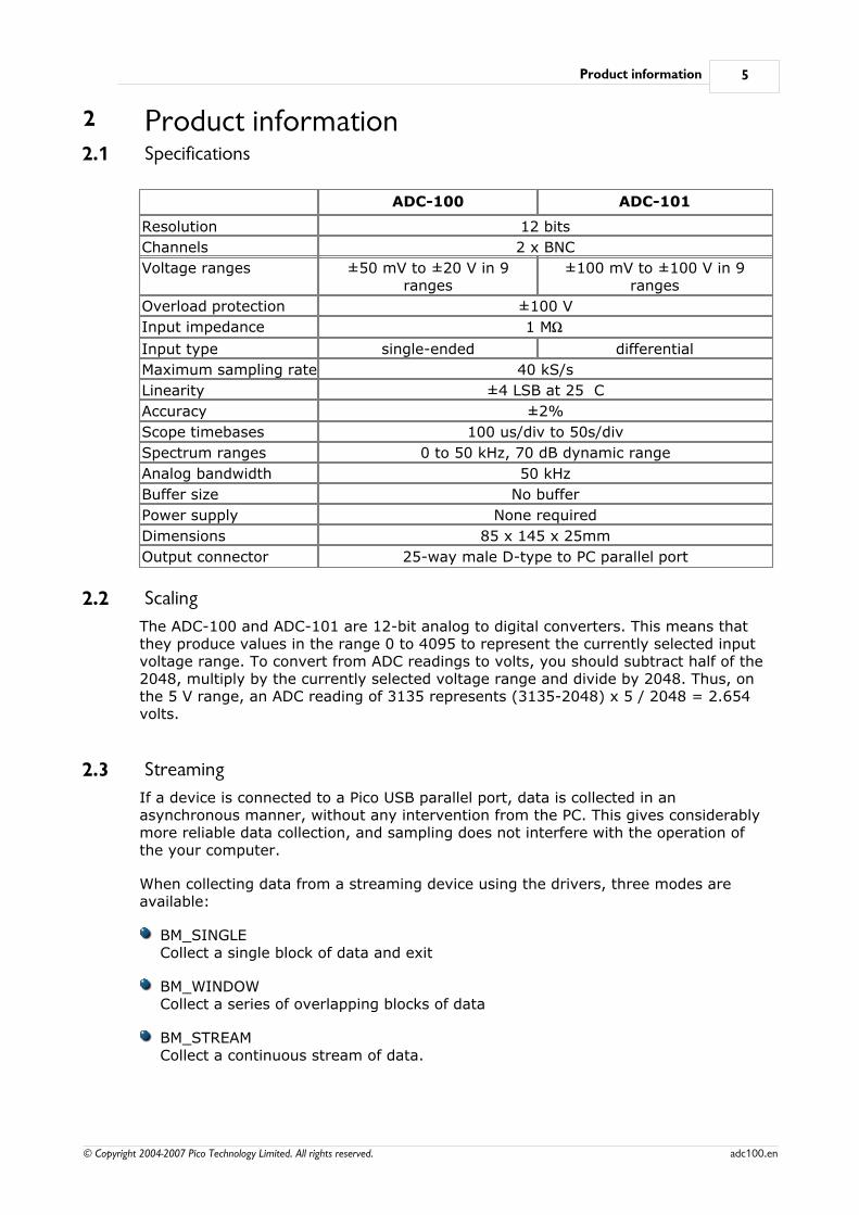
2 Product information2.1 Specifications
ADC-100 ADC-101
Resolution 12 bits
Channels 2 x BNC
Voltage ranges ±50 mV to ±20 V in 9ranges
±100 mV to ±100 V in 9ranges
Overload protection ±100 V
Input impedance 1 MW
Input type single-ended differential
Maximum sampling rate 40 kS/s
Linearity ±4 LSB at 25 C
Accuracy ±2%
Scope timebases 100 us/div to 50s/div
Spectrum ranges 0 to 50 kHz, 70 dB dynamic range
Analog bandwidth 50 kHz
Buffer size No buffer
Power supply None required
Dimensions 85 x 145 x 25mm
Output connector 25-way male D-type to PC parallel port
2.2 Scaling
The ADC-100 and ADC-101 are 12-bit analog to digital converters. This means thatthey produce values in the range 0 to 4095 to represent the currently selected inputvoltage range. To convert from ADC readings to volts, you should subtract half of the2048, multiply by the currently selected voltage range and divide by 2048. Thus, onthe 5 V range, an ADC reading of 3135 represents (3135-2048) x 5 / 2048 = 2.654volts.
2.3 Streaming
If a device is connected to a Pico USB parallel port, data is collected in an asynchronous manner, without any intervention from the PC. This gives considerablymore reliable data collection, and sampling does not interfere with the operation ofthe your computer.
When collecting data from a streaming device using the drivers, three modes areavailable:
BM_SINGLECollect a single block of data and exit
BM_WINDOWCollect a series of overlapping blocks of data
BM_STREAMCollect a continuous stream of data.
ADC-100 User's Guide6
© Copyright 2004-2007 Pico Technology Limited. All rights reserved.adc100.en
BM_SINGLE is useful when you wish to collect data at high speed for a relatively short
period. For example, to collect 1000 readings in 50 ms.
BM_WINDOW is useful when collecting several blocks of data at relatively low speeds- for
example when collecting 10000 samples over 10 seconds. Collecting a sequence ofSINGLE blocks like this would take 10 seconds for each block, so displayed data wouldnot be updated frequently. Using windowing, it is possible to ask for a new block morefrequently, for example every second, and to receive a block containing nine secondsof data that have already been seen and one second of new data. The block iseffectively a 10-second 'window' that advances one second each time.
BM_STREAM is useful when you need to collect data continuously for long periods. In
principle, it would be possible to collect data indefinitely. Each time adc100_get_values is called, it returns the new readings since the last time it wascalled. No_of_values passed to adc100_run must be sufficient to ensure that the
buffer does not overflow between successive calls to adc100_get_values. Forexample, if you call adc100_get_values every second, and you are collecting 500samples per second, no_of_values must be at least 500, and preferably 1000 to give
some allowance for delays in the operating system.
Technical reference 7
© Copyright 2004-2007 Pico Technology Limited. All rights reserved. adc100.en
3 Technical reference3.1 Introduction
The ADC-100 and ADC-101 are supplied with driver routines that you can build intoyour own programs.
Once you have installed the software, the DRIVERS sub-directory contains the driversand a selection of examples of how to use the drivers. It also contains a copy of thishelp file in text format.
The driver routines are supplied as Dynamic Link Libraries for Windows 95/98/ME andNT/200/XP.
The Windows DLLs can be used with any programming language or application thatcan interface with DLLs- for example, C, Delphi, Visual Basic, Excel, LabVIEW, etc.The DRIVERS directory contains example programs for several popular programminglanguages or applications: some of these examples are fairly simple, but the C consolemode example, a100con.c, shows how to use all facilities in the driver.
The driver is capable of supporting up to three units connected to printer ports (oneeach on LPT1, LPT2 and LPT3) and up to four Pico USB parallel port units. The unitscan be any mixture of ADC-100 and ADC-101.
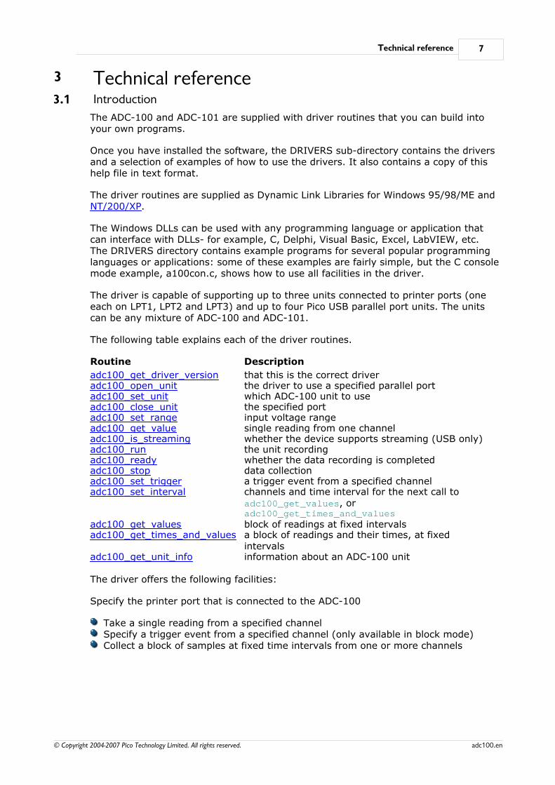
The following table explains each of the driver routines.
Routine Description
adc100_get_driver_version that this is the correct driveradc100_open_unit the driver to use a specified parallel portadc100_set_unit which ADC-100 unit to useadc100_close_unit the specified portadc100_set_range input voltage rangeadc100_get_value single reading from one channeladc100_is_streaming whether the device supports streaming (USB only)adc100_run the unit recordingadc100_ready whether the data recording is completedadc100_stop data collectionadc100_set_trigger a trigger event from a specified channeladc100_set_interval channels and time interval for the next call to
adc100_get_values, oradc100_get_times_and_values
adc100_get_values block of readings at fixed intervalsadc100_get_times_and_values a block of readings and their times, at fixed
intervalsadc100_get_unit_info information about an ADC-100 unit
The driver offers the following facilities:
Specify the printer port that is connected to the ADC-100
Take a single reading from a specified channelSpecify a trigger event from a specified channel (only available in block mode)Collect a block of samples at fixed time intervals from one or more channels
ADC-100 User's Guide8
© Copyright 2004-2007 Pico Technology Limited. All rights reserved.adc100.en
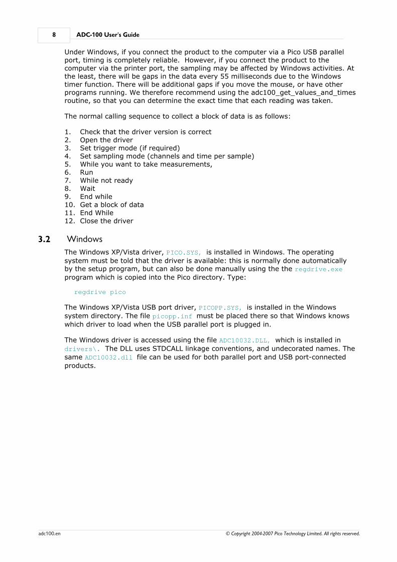
Under Windows, if you connect the product to the computer via a Pico USB parallelport, timing is completely reliable. However, if you connect the product to thecomputer via the printer port, the sampling may be affected by Windows activities. Atthe least, there will be gaps in the data every 55 milliseconds due to the Windowstimer function. There will be additional gaps if you move the mouse, or have otherprograms running. We therefore recommend using the adc100_get_values_and_timesroutine, so that you can determine the exact time that each reading was taken.
The normal calling sequence to collect a block of data is as follows:
1. Check that the driver version is correct2. Open the driver3. Set trigger mode (if required)4. Set sampling mode (channels and time per sample)5. While you want to take measurements,6. Run7. While not ready8. Wait9. End while10. Get a block of data11. End While12. Close the driver
3.2 Windows
The Windows XP/Vista driver, PICO.SYS, is installed in Windows. The operating
system must be told that the driver is available: this is normally done automaticallyby the setup program, but can also be done manually using the the regdrive.exe
program which is copied into the Pico directory. Type:
regdrive pico
The Windows XP/Vista USB port driver, PICOPP.SYS, is installed in the Windows
system directory. The file picopp.inf must be placed there so that Windows knows
which driver to load when the USB parallel port is plugged in.
The Windows driver is accessed using the file ADC10032.DLL, which is installed in
drivers\. The DLL uses STDCALL linkage conventions, and undecorated names. The
same ADC10032.dll file can be used for both parallel port and USB port-connected
products.
Technical reference 9
© Copyright 2004-2007 Pico Technology Limited. All rights reserved. adc100.en
3.3 Driver routines
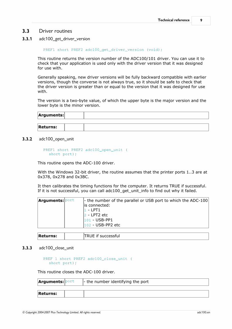
3.3.1 adc100_get_driver_version
PREF1 short PREF2 adc100_get_driver_version (void);
This routine returns the version number of the ADC100/101 driver. You can use it tocheck that your application is used only with the driver version that it was designedfor use with.
Generally speaking, new driver versions will be fully backward compatible with earlierversions, though the converse is not always true, so it should be safe to check thatthe driver version is greater than or equal to the version that it was designed for usewith.
The version is a two-byte value, of which the upper byte is the major version and thelower byte is the minor version.
Arguments:
Returns:
3.3.2 adc100_open_unit
PREF1 short PREF2 adc100_open_unit (short port);
This routine opens the ADC-100 driver.
With the Windows 32-bit driver, the routine assumes that the printer ports 1..3 are at0x378, 0x278 and 0x3BC.
It then calibrates the timing functions for the computer. It returns TRUE if successful.If it is not successful, you can call adc100_get_unit_info to find out why it failed.
Arguments: port - the number of the parallel or USB port to which the ADC-100is connected:1 - LPT1
2 - LPT2 etc
101 - USB-PP1
102 - USB-PP2 etc
Returns: TRUE if successful
3.3.3 adc100_close_unit
PREF 1 short PREF2 adc100_close_unit (short port);
This routine closes the ADC-100 driver.
Arguments: port - the number identifying the port
Returns:
ADC-100 User's Guide10
© Copyright 2004-2007 Pico Technology Limited. All rights reserved.adc100.en
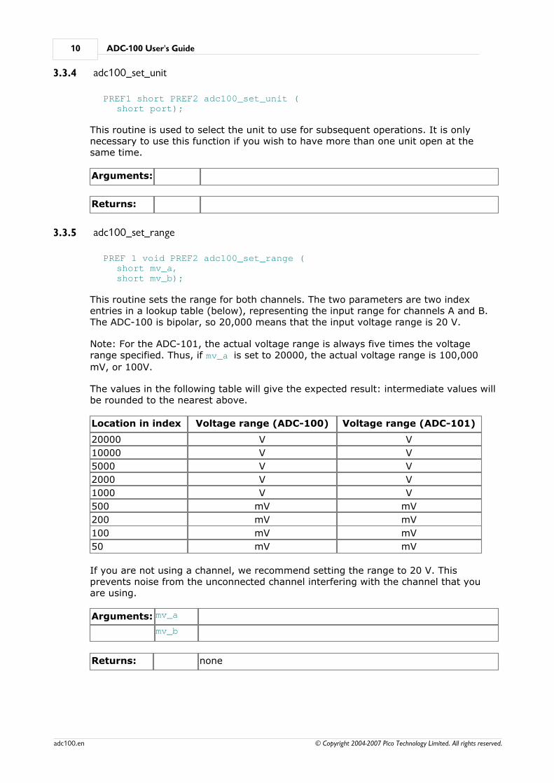
3.3.4 adc100_set_unit
PREF1 short PREF2 adc100_set_unit (short port);
This routine is used to select the unit to use for subsequent operations. It is onlynecessary to use this function if you wish to have more than one unit open at thesame time.
Arguments:
Returns:
3.3.5 adc100_set_range
PREF 1 void PREF2 adc100_set_range (short mv_a, short mv_b);
This routine sets the range for both channels. The two parameters are two indexentries in a lookup table (below), representing the input range for channels A and B.The ADC-100 is bipolar, so 20,000 means that the input voltage range is 20 V.
Note: For the ADC-101, the actual voltage range is always five times the voltagerange specified. Thus, if mv_a is set to 20000, the actual voltage range is 100,000
mV, or 100V.
The values in the following table will give the expected result: intermediate values willbe rounded to the nearest above.
Location in index Voltage range (ADC-100) Voltage range (ADC-101)
20000 V V
10000 V V
5000 V V
2000 V V
1000 V V
500 mV mV
200 mV mV
100 mV mV
50 mV mV
If you are not using a channel, we recommend setting the range to 20 V. Thisprevents noise from the unconnected channel interfering with the channel that youare using.
Arguments: mv_a
mv_b
Returns: none
Technical reference 11
© Copyright 2004-2007 Pico Technology Limited. All rights reserved. adc100.en
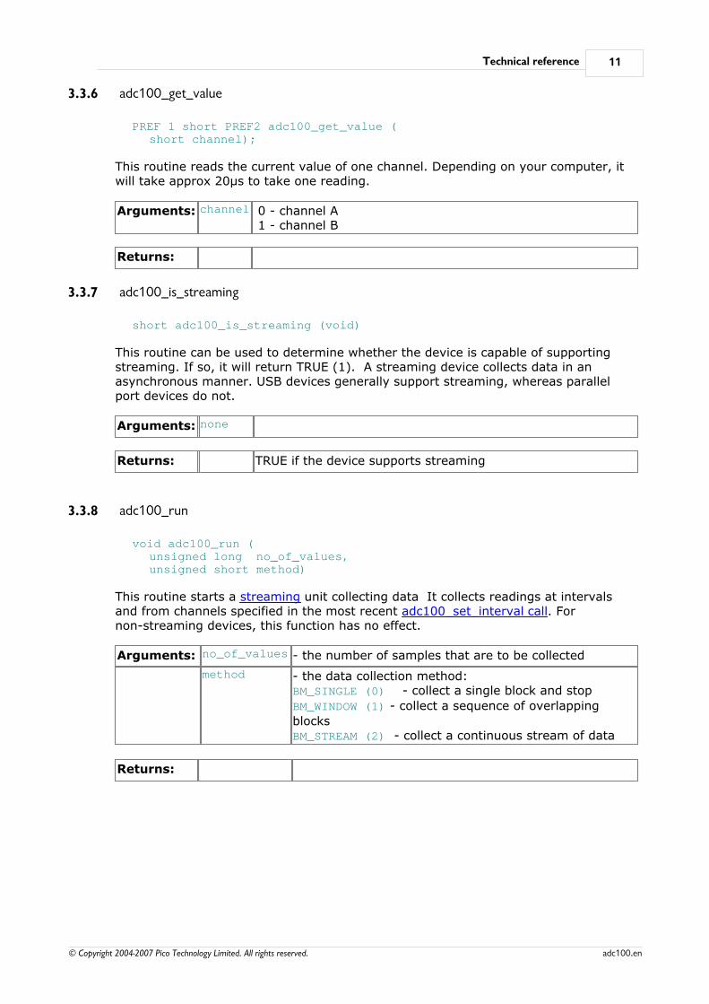
3.3.6 adc100_get_value
PREF 1 short PREF2 adc100_get_value (short channel);
This routine reads the current value of one channel. Depending on your computer, itwill take approx 20µs to take one reading.
Arguments: channel 0 - channel A 1 - channel B
Returns:
3.3.7 adc100_is_streaming
short adc100_is_streaming (void)
This routine can be used to determine whether the device is capable of supporting streaming. If so, it will return TRUE (1). A streaming device collects data in anasynchronous manner. USB devices generally support streaming, whereas parallelport devices do not.
Arguments: none
Returns: TRUE if the device supports streaming
3.3.8 adc100_run
void adc100_run (unsigned long no_of_values, unsigned short method)
This routine starts a streaming unit collecting data It collects readings at intervalsand from channels specified in the most recent adc100_set_interval call. Fornon-streaming devices, this function has no effect.
Arguments: no_of_values - the number of samples that are to be collected
method - the data collection method: BM_SINGLE (0) - collect a single block and stop
BM_WINDOW (1) - collect a sequence of overlapping
blocksBM_STREAM (2) - collect a continuous stream of data
Returns:
ADC-100 User's Guide12
© Copyright 2004-2007 Pico Technology Limited. All rights reserved.adc100.en
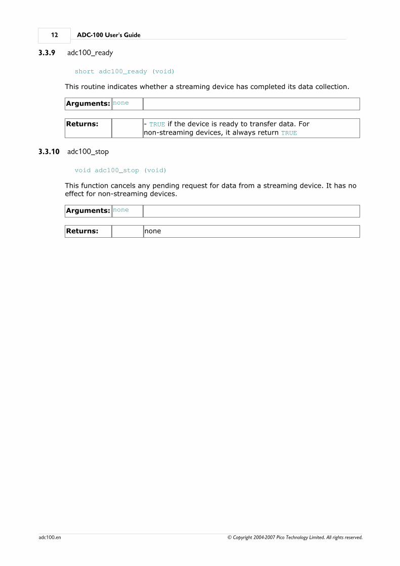
3.3.9 adc100_ready
short adc100_ready (void)
This routine indicates whether a streaming device has completed its data collection.
Arguments: none
Returns: - TRUE if the device is ready to transfer data. For
non-streaming devices, it always return TRUE
3.3.10 adc100_stop
void adc100_stop (void)
This function cancels any pending request for data from a streaming device. It has noeffect for non-streaming devices.
Arguments: none
Returns: none
Technical reference 13
© Copyright 2004-2007 Pico Technology Limited. All rights reserved. adc100.en
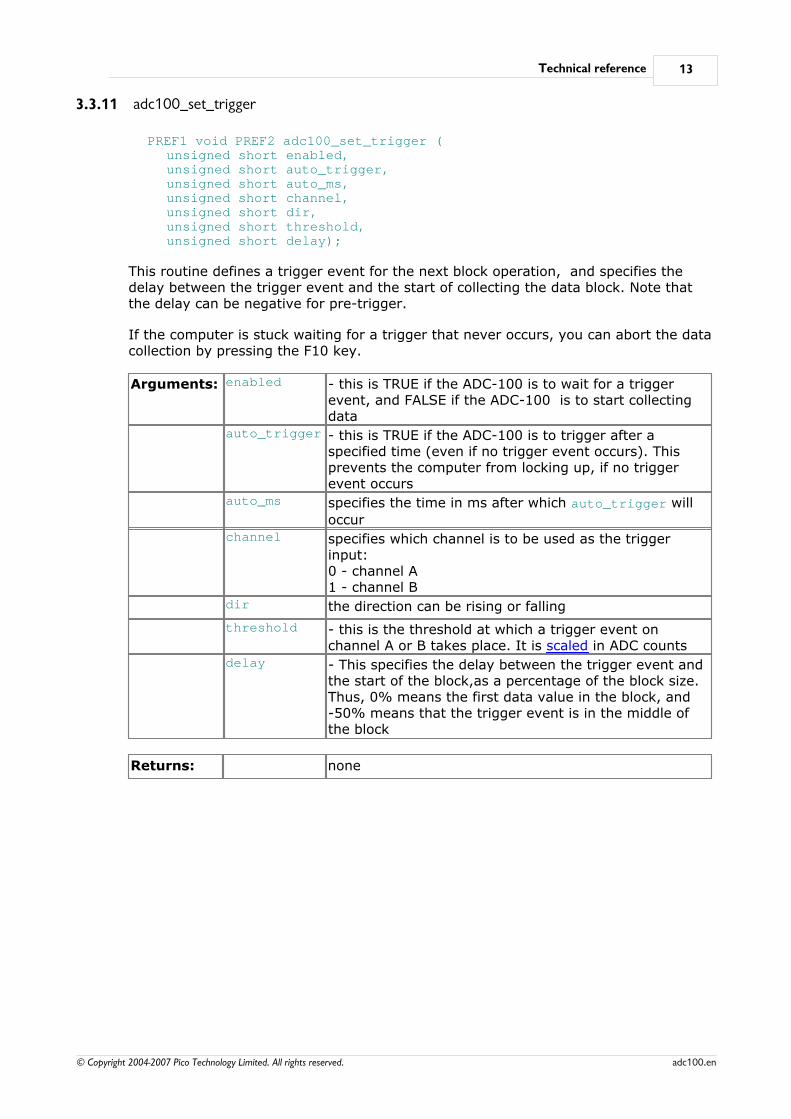
3.3.11 adc100_set_trigger
PREF1 void PREF2 adc100_set_trigger (unsigned short enabled,unsigned short auto_trigger,unsigned short auto_ms,unsigned short channel,unsigned short dir,unsigned short threshold,unsigned short delay);
This routine defines a trigger event for the next block operation, and specifies thedelay between the trigger event and the start of collecting the data block. Note thatthe delay can be negative for pre-trigger.
If the computer is stuck waiting for a trigger that never occurs, you can abort the datacollection by pressing the F10 key.
Arguments: enabled - this is TRUE if the ADC-100 is to wait for a triggerevent, and FALSE if the ADC-100 is to start collectingdata
auto_trigger - this is TRUE if the ADC-100 is to trigger after aspecified time (even if no trigger event occurs). Thisprevents the computer from locking up, if no triggerevent occurs
auto_ms specifies the time in ms after which auto_trigger will
occurchannel specifies which channel is to be used as the trigger
input:0 - channel A1 - channel B
dir the direction can be rising or falling
threshold - this is the threshold at which a trigger event onchannel A or B takes place. It is scaled in ADC counts
delay - This specifies the delay between the trigger event andthe start of the block,as a percentage of the block size.Thus, 0% means the first data value in the block, and-50% means that the trigger event is in the middle ofthe block
Returns: none
ADC-100 User's Guide14
© Copyright 2004-2007 Pico Technology Limited. All rights reserved.adc100.en
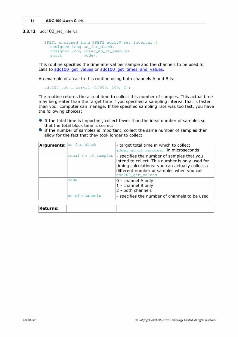
3.3.12 adc100_set_interval
PREF1 unsigned long PREF2 adc100_set_interval (unsigned long us_for_block,unsigned long ideal_no_of_samples,short mode);
This routine specifies the time interval per sample and the channels to be used forcalls to adc100_get_values or adc100_get_times_and_values.
An example of a call to this routine using both channels A and B is:
adc100_set_interval (10000, 100, 2);
The routine returns the actual time to collect this number of samples. This actual timemay be greater than the target time if you specified a sampling interval that is fasterthan your computer can manage. If the specified sampling rate was too fast, you havethe following choices:
If the total time is important, collect fewer than the ideal number of samples sothat the total block time is correctIf the number of samples is important, collect the same number of samples thenallow for the fact that they took longer to collect.
Arguments: us_for_block - target total time in which to collect ideal_no_of samples, in microseconds
ideal_no_of_samples - specifies the number of samples that youintend to collect. This number is only used fortiming calculations: you can actually collect adifferent number of samples when you call adc100_get_values
mode 0 - channel A only1 - channel B only2 - both channels
no_of_channels - specifies the number of channels to be used
Returns:
Technical reference 15
© Copyright 2004-2007 Pico Technology Limited. All rights reserved. adc100.en
3.3.13 adc100_get_values
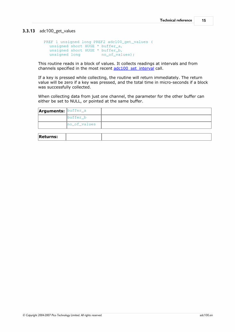
PREF 1 unsigned long PREF2 adc100_get_values (unsigned short HUGE * buffer_a,unsigned short HUGE * buffer_b, unsigned long no_of_values);
This routine reads in a block of values. It collects readings at intervals and fromchannels specified in the most recent adc100_set_interval call.
If a key is pressed while collecting, the routine will return immediately. The returnvalue will be zero if a key was pressed, and the total time in micro-seconds if a blockwas successfully collected.
When collecting data from just one channel, the parameter for the other buffer caneither be set to NULL, or pointed at the same buffer.
Arguments: buffer_a
buffer_b
no_of_values
Returns:
ADC-100 User's Guide16
© Copyright 2004-2007 Pico Technology Limited. All rights reserved.adc100.en
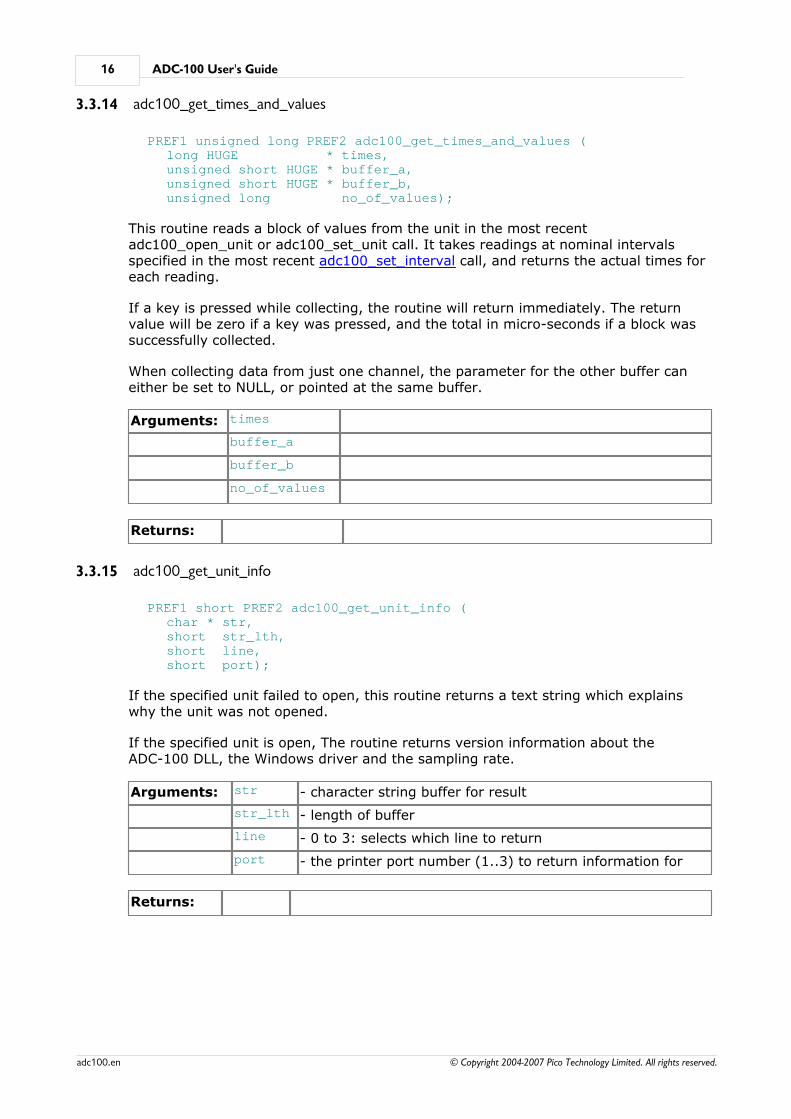
3.3.14 adc100_get_times_and_values
PREF1 unsigned long PREF2 adc100_get_times_and_values (long HUGE * times, unsigned short HUGE * buffer_a, unsigned short HUGE * buffer_b, unsigned long no_of_values);
This routine reads a block of values from the unit in the most recentadc100_open_unit or adc100_set_unit call. It takes readings at nominal intervalsspecified in the most recent adc100_set_interval call, and returns the actual times foreach reading.
If a key is pressed while collecting, the routine will return immediately. The returnvalue will be zero if a key was pressed, and the total in micro-seconds if a block wassuccessfully collected.
When collecting data from just one channel, the parameter for the other buffer caneither be set to NULL, or pointed at the same buffer.
Arguments: times
buffer_a
buffer_b
no_of_values
Returns:
3.3.15 adc100_get_unit_info
PREF1 short PREF2 adc100_get_unit_info (char * str, short str_lth, short line, short port);
If the specified unit failed to open, this routine returns a text string which explainswhy the unit was not opened.
If the specified unit is open, The routine returns version information about theADC-100 DLL, the Windows driver and the sampling rate.
Arguments: str - character string buffer for result
str_lth - length of buffer
line - 0 to 3: selects which line to return
port - the printer port number (1..3) to return information for
Returns:
Technical reference 17
© Copyright 2004-2007 Pico Technology Limited. All rights reserved. adc100.en
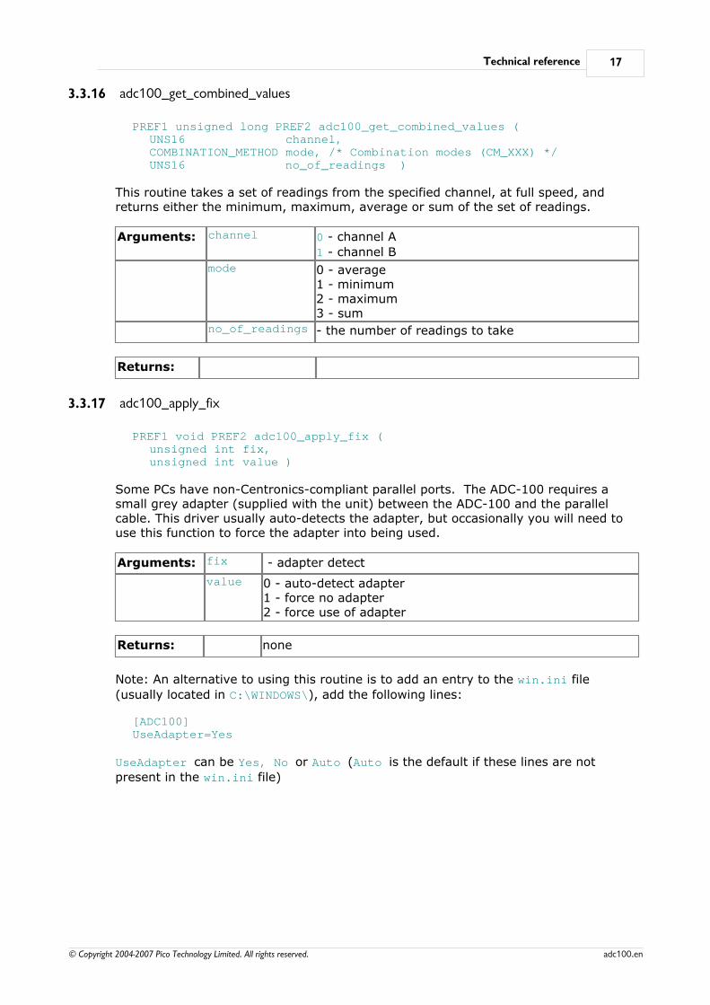
3.3.16 adc100_get_combined_values
PREF1 unsigned long PREF2 adc100_get_combined_values (UNS16 channel,COMBINATION_METHOD mode, /* Combination modes (CM_XXX) */UNS16 no_of_readings )
This routine takes a set of readings from the specified channel, at full speed, andreturns either the minimum, maximum, average or sum of the set of readings.
Arguments: channel 0 - channel A
1 - channel B
mode 0 - average1 - minimum2 - maximum3 - sum
no_of_readings - the number of readings to take
Returns:
3.3.17 adc100_apply_fix
PREF1 void PREF2 adc100_apply_fix (unsigned int fix,unsigned int value )
Some PCs have non-Centronics-compliant parallel ports. The ADC-100 requires asmall grey adapter (supplied with the unit) between the ADC-100 and the parallelcable. This driver usually auto-detects the adapter, but occasionally you will need touse this function to force the adapter into being used.
Arguments: fix - adapter detect
value 0 - auto-detect adapter1 - force no adapter2 - force use of adapter
Returns: none
Note: An alternative to using this routine is to add an entry to the win.ini file
(usually located in C:\WINDOWS\), add the following lines:
[ADC100]UseAdapter=Yes
UseAdapter can be Yes, No or Auto (Auto is the default if these lines are not
present in the win.ini file)
ADC-100 User's Guide18
© Copyright 2004-2007 Pico Technology Limited. All rights reserved.adc100.en
3.4 Programming
3.4.1 C / C++
C
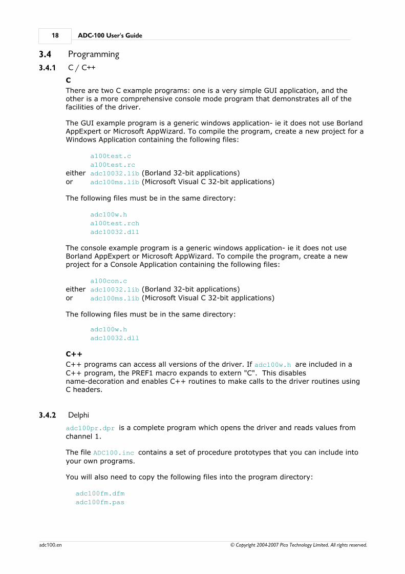
There are two C example programs: one is a very simple GUI application, and theother is a more comprehensive console mode program that demonstrates all of thefacilities of the driver.
The GUI example program is a generic windows application- ie it does not use BorlandAppExpert or Microsoft AppWizard. To compile the program, create a new project for aWindows Application containing the following files:
a100test.c
a100test.rc
either adc10032.lib (Borland 32-bit applications)
or adc100ms.lib (Microsoft Visual C 32-bit applications)
The following files must be in the same directory:
adc100w.h
a100test.rch
adc10032.dll
The console example program is a generic windows application- ie it does not useBorland AppExpert or Microsoft AppWizard. To compile the program, create a newproject for a Console Application containing the following files:
a100con.c
either adc10032.lib (Borland 32-bit applications)
or adc100ms.lib (Microsoft Visual C 32-bit applications)
The following files must be in the same directory:
adc100w.h
adc10032.dll
C++
C++ programs can access all versions of the driver. If adc100w.h are included in a
C++ program, the PREF1 macro expands to extern "C". This disablesname-decoration and enables C++ routines to make calls to the driver routines usingC headers.
3.4.2 Delphi
adc100pr.dpr is a complete program which opens the driver and reads values from
channel 1.
The file ADC100.inc contains a set of procedure prototypes that you can include into
your own programs.
You will also need to copy the following files into the program directory:
adc100fm.dfm
adc100fm.pas
Technical reference 19
© Copyright 2004-2007 Pico Technology Limited. All rights reserved. adc100.en
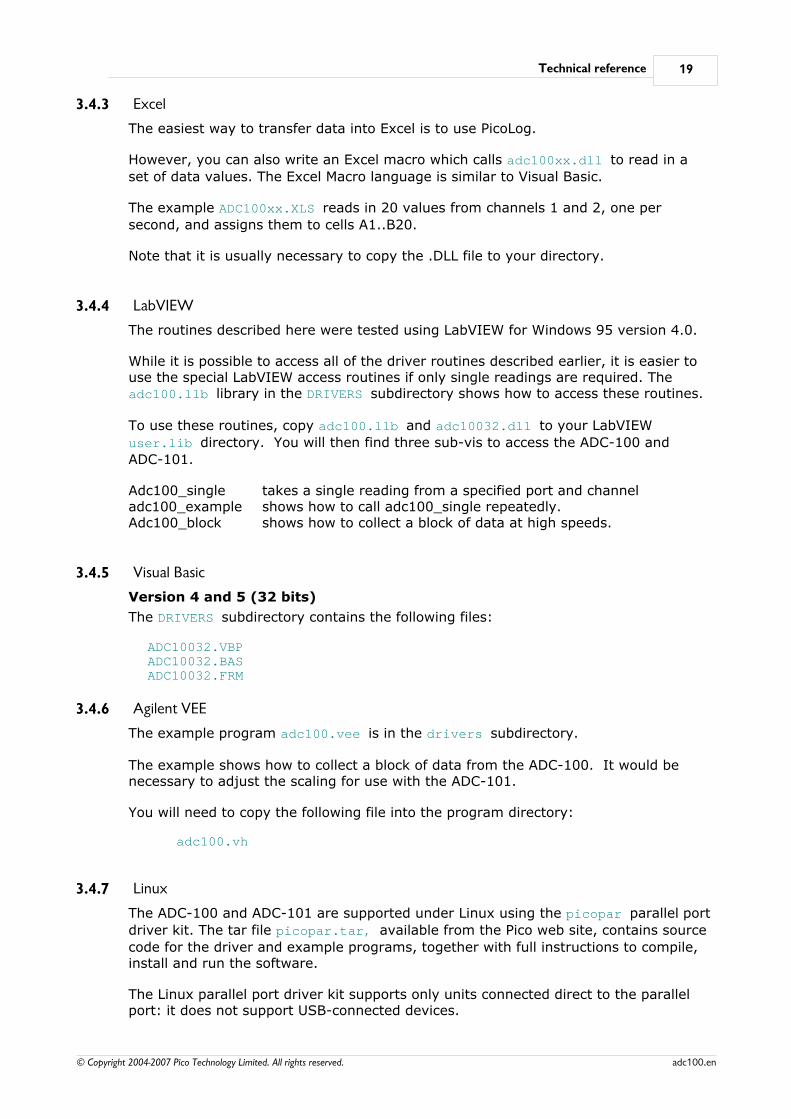
3.4.3 Excel
The easiest way to transfer data into Excel is to use PicoLog.
However, you can also write an Excel macro which calls adc100xx.dll to read in a
set of data values. The Excel Macro language is similar to Visual Basic.
The example ADC100xx.XLS reads in 20 values from channels 1 and 2, one per
second, and assigns them to cells A1..B20.
Note that it is usually necessary to copy the .DLL file to your directory.
3.4.4 LabVIEW
The routines described here were tested using LabVIEW for Windows 95 version 4.0.
While it is possible to access all of the driver routines described earlier, it is easier touse the special LabVIEW access routines if only single readings are required. The adc100.llb library in the DRIVERS subdirectory shows how to access these routines.
To use these routines, copy adc100.llb and adc10032.dll to your LabVIEW
user.lib directory. You will then find three sub-vis to access the ADC-100 and
ADC-101.
Adc100_single takes a single reading from a specified port and channeladc100_example shows how to call adc100_single repeatedly.Adc100_block shows how to collect a block of data at high speeds.
3.4.5 Visual Basic
Version 4 and 5 (32 bits)
The DRIVERS subdirectory contains the following files:
ADC10032.VBPADC10032.BASADC10032.FRM
3.4.6 Agilent VEE
The example program adc100.vee is in the drivers subdirectory.
The example shows how to collect a block of data from the ADC-100. It would benecessary to adjust the scaling for use with the ADC-101.
You will need to copy the following file into the program directory:
adc100.vh
3.4.7 Linux
The ADC-100 and ADC-101 are supported under Linux using the picopar parallel port
driver kit. The tar file picopar.tar, available from the Pico web site, contains source
code for the driver and example programs, together with full instructions to compile,install and run the software.
The Linux parallel port driver kit supports only units connected direct to the parallelport: it does not support USB-connected devices.

ADC-100 User's Guide20
© Copyright 2004-2007 Pico Technology Limited. All rights reserved.adc100.en
Index 21
© Copyright 2004-2007 Pico Technology Limited. All rights reserved. adc100.en
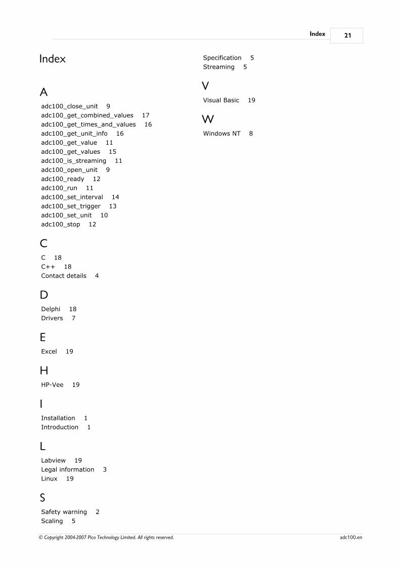
Index
Aadc100_close_unit 9
adc100_get_combined_values 17
adc100_get_times_and_values 16
adc100_get_unit_info 16
adc100_get_value 11
adc100_get_values 15
adc100_is_streaming 11
adc100_open_unit 9
adc100_ready 12
adc100_run 11
adc100_set_interval 14
adc100_set_trigger 13
adc100_set_unit 10
adc100_stop 12
CC 18
C++ 18
Contact details 4
DDelphi 18
Drivers 7
EExcel 19
HHP-Vee 19
IInstallation 1
Introduction 1
LLabview 19
Legal information 3
Linux 19
SSafety warning 2
Scaling 5
Specification 5
Streaming 5
VVisual Basic 19
WWindows NT 8

ADC-100 User's Guide22
adc100.en © Copyright 2004-2007 Pico Technology Limited. All rights reserved.

Pico Technology Ltd
The Mill HouseCambridge Street
St Neots PE19 1QBUnited Kingdom
Tel: +44 (0) 1480 396 395Fax: +44 (0) 1480 396 296Web: www.picotech.com
© Copyright 2004-2007 Pico Technology Limited. All rights reserved.adc100.en 1.10.07